

Page 1

Operating manual
System
LIFEBOOK T901
Page 2

Congratulations, you have
innovative Fujitsu product.
decided to buy an
The latest information about our products, useful tips, updates etc. is available
from our website: "
For automatic driver updates, go to: "http://support.ts.fujitsu.com/com/support/index.html"
Should you have any technical questions, please contact:
• our Hotline/Service Desk (see Service Desk list or visit:
"
http://ts.fujitsu.com/support/servicedesk.html")
• Your sales partner
• Your sales office
We hope you really enjoy using your new Fujitsu system.
http://ts.fujitsu.com"
Page 3

Page 4

Copyright
Fujitsu Tec
Published by
Fujitsu Technology Solutions
Mies-van80807 Munich, Germany
Contact
h
All rights reserved, including intellectual property rights. Subject to technical alterations. Delivery subject to availability.
No warra nty is offered or liability accepted in regard of the completeness, correctness, or cu rr ent app licability of any
data or
by copyright. Use of these by third parties for their own purposes may constitute an infringement of the holders’
rights. Further information can be found at "
hnology Solutions 2011 05/11
der-Rohe-Straße 8 (Mies-van-der-Rohe Street No. 8)
s.fujitsu.com/support
ttp://t
illustrations. Brand names may be protecte d trademarks of the respective manufacturer and/or protected
http://ts.fujitsu.com/terms_of_use.html"
Order No. Fujitsu Technology Solutions GmbH: A26391-K333-Z320-1-7619, edition 2
Page 5

LIFEBOOK T901
Operating manual
Innovative technology 7
Ports and controls 9
Important notes 13
First-time setup of your device 16
Working with the notebook 19
Security functions 76
Connecting external devices 97
Removing and installing components
during servicing 105
Settings in BIOS Setup Utility 113
Troubleshooting and tips 115
Technical data 123
Manufacturer’s notes 126
Index 133
Page 6

Microsoft, MS, Windows XP and Windows 7 are registered trademarks of the Microsoft Corporation.
Adobe Reader is a trademark of Adobe Systems Incorporated.
MultiMediaCard is a registered tradem ark of Infineon Technologies AG
Sony and Memory Stick are registered trademarks of Sony Electronics, Inc.
All other trademarks referenced are trademarks or registered trademarks of their
respective owners, whose protected rights are acknowledged.
Copyright © Fujitsu Technology Solutions GmbH 2011
All rights r eserved, including rights of translation, reproduction by printing, copying
or similar methods, in part or in whole.
In the event of violations, perpetrators will be liable to prosecution for damages.
All rights reserved, including rights created by patent grant or registration of a utility model or design.
Subject to availability and technical modifications.
Page 7

Contents
Contents
Innovativetechnology ................................................................. 7
Furtherinformation ...................................................................... 7
Notational conventions .................................................................. 8
Portsand controls ..................................................................... 9
Importantnotes ........................................................................ 13
Safetynotes ............................................................................ 13
Additional safety notes for devices with radio components . . . . . ............................. 13
Energysaving .......................................................................... 14
Energy saving under Windows ....................................................... 14
Travellingwithyournotebook ............................................................ 14
Before you travel ................................................................... 14
Notebook: transporting ............................................................... 15
Cleaning the notebook .................................................................. 15
First-time setup o
Unpacking and che
Selectingalocat
Mains adapter con
Switchingonthe
Working withthe notebook ............................................................ 19
Status indicators ........................................................................ 19
Opening the notebook ................................................................... 21
Switching on the notebook . . . . ........................................................... 22
Programming theON/OFFswitch ..................................................... 22
Different ways to use your notebook . . . ................................................... 23
From noteboo k to Tablet PC . . ....................................................... 23
Select displayorientation (portrait or landscape orientation) ............................. 25
From Tablet PC tonotebook .......................................................... 26
Switching off the notebook . . . . ........................................................... 29
Closing the notebook . . .................................................................. 29
Language selection (Windows XP only) ................................................... 30
Selecting the language for menu texts . . . . ............................................ 30
Selecting the language for handwriting recognition and keyboard . . . ..................... 30
Handwriting recognition under Windows Vista . ........................................ 30
Handwriting recognition under Windows 7 . ............................................ 30
LCDscreen ............................................................................ 31
Ambient LightSensor ................................................................ 31
Using adevice as a tablet PC ............................................................ 31
Using fingers ....................................................................... 32
Using the stylus pen ................................................................. 34
Using the deviceasa notebook .......................................................... 38
Touchpad andtouchpadbuttons ...................................................... 38
ScrollWheel . . .......................................................................... 39
Scrolling downwards or forwards ..................................................... 40
Scrolling upwards or backwards ...................................................... 40
Back one pagein Web browser ...................................................... 40
Keyboard ............................................................................... 40
Virtual numeric keypad .............................................................. 43
Country and keyboard settings ....................................................... 43
fyourdevice .........................................................
cking the device ......................................................
ion .....................................................................
necting ...............................................................
device for the firsttime ..................................................
16
16
17
17
18
Fujitsu Technology Solutions 3
Page 8

Contents
Key combinations ................................................................... 43
Tablet buttons .......................................................................... 45
Key combinations ................................................................... 49
Programming thetabletbuttons ...................................................... 49
Webcam ............................................................................... 50
Rechargeable battery . . . ................................................................ 50
Charging, caringforandmaintaining the battery ....................................... 51
Removing and installing the battery ................................................... 52
Batteries w ith a capacity of 5800 mAh or 6200 mAh . . .................................. 54
Module ................................................................................. 55
Removing a module . ................................................................ 55
Installing a module . . ................................................................ 56
Optical drive ............................................................................ 56
Handling data carriers . . . ............................................................ 56
CD/DVD indicator ................................................................... 56
Inserting or removinga datacarrier ................................................... 57
Manual removal (emergency removal) . . . ............................................. 57
Removing andreplacing the casing cover (ventilation slotcover)togetridof dust ............ 58
Using the power-management features . . ................................................. 59
Memory cards .......................................................................... 60
Supported formats .................................................................. 60
Inserting thememorycard ........................................................... 60
Removing the memorycard .......................................................... 61
ExpressCards .......................................................................... 62
Inserting thecard ................................................................... 62
Removing the card .................................................................. 63
Loudspeakers and microphones . . ........................................................ 63
Integrated 56k modem . . ................................................................ 64
Connecting notebook modem to telephone wall socket . . . .............................. 65
SIM card ............................................................................... 65
Inserting theSIM card ............................................................... 66
Removing aSIM card ............................................................... 67
Optional W ireless LAN / BlueTooth / UMTS wireless components . .......................... 67
Switching the wireless components on and off ......................................... 68
Setting up WLANaccess ............................................................ 68
Access via UMTS ................................................................... 69
UMTS antenna ...................................................................... 69
Ethernet and LAN ....................................................................... 70
Your Port Replicator (optional) . . . ........................................................ 71
Ports on thePort Replicator .......................................................... 71
Setting up theportreplicator ......................................................... 72
Connect the notebook to the port replicator . . . ......................................... 73
Switching on the notebook via the port replicator . . . . . .................................. 74
Switching offnotebook via PortReplicator ............................................. 74
Disconnecting the notebook from the port replicator . . .................................. 75
Security functions ..................................................................... 76
Brief overviewofsecurity functions ....................................................... 77
Configuring the fingerprint sensor ........................................................ 78
Using the Security Lock ................................................................. 78
Configuring passwordprotection in BIOSSetupUtility ...................................... 79
Protecting BIOS Setup Utility (supervisor and user password) . .......................... 79
Password prote ction for booting of the operating system . .............................. 80
4 Fujitsu Technology Solutions
Page 9

Contents
Password protection for theharddisk ................................................. 81
SmartCard reader . ...................................................................... 82
Inserting theSmartCard ............................................................. 82
SmartCard SystemLock (optional) ........................................................ 83
Access rightsof SmartCards ......................................................... 84
SmartCard user groups . . . ........................................................... 85
Installing SystemLock ............................................................... 86
Setting up the first system in a user group or a stand-alone system for use with SystemLock
..................................................................................... 86
Adding asystem toa user group ..................................................... 89
Carrying out administrator functions ................................................... 91
F4
Remote Access Enabling –
...................................................... 93
Switch on thedeviceusing SystemLock ............................................... 94
F2
Start BIO S Setup
............................................................... 94
Changing PIN . ...................................................................... 94
Uninstall SystemLock ................................................................ 94
Error messages ..................................................................... 95
Using the security functionof the tablet keys .............................................. 95
Setting the Supervisor password . . ................................................... 95
Setting the User password ........................................................... 95
Entering passwords using thetablet buttons ........................................... 96
Trusted Platform Module (TPM) (device-dependent) . . . .................................... 96
Enabling TPM . ...................................................................... 96
Disabling TPM ...................................................................... 96
Connecting external devices ........................................................... 97
Connecting an external monitor . . . ....................................................... 98
Connecting an external monitor to the DisplayPort . .................................... 99
HDMI port .......................................................................... 100
Connecting USB devices . . . . . ........................................................... 101
USB port withcharging function (AnytimeUSBcharge) ................................. 102
How to removeUSB devices correctly ................................................ 102
Connecting FireWire devices . . ........................................................... 103
Connecting external audio devices ....................................................... 103
Microphone port/Line In . . . ........................................................... 103
Headphone port . . . .................................................................. 104
Removing and installing components during servicing . . . . ............................. 105
Notes on installing and removing boards andcomponents .................................. 105
Preparing to remove components . ....................................................... 106
Installing and removing memory expansion . . . . ............................................ 106
Removing acover ................................................................... 107
Removing memorymodules .......................................................... 107
Installing amemorymodule .......................................................... 108
Attaching thecover .................................................................. 108
Removing and installing the hard disk .................................................... 109
Removing acover ................................................................... 109
Removing ahard disk ............................................................... 110
Installing aharddisk ................................................................. 111
Attaching thecover .................................................................. 112
Finishing component removal . ........................................................... 112
Settings in BIO S Setup Utility . . . ....................................................... 113
Starting the BIOS Setup Utility ........................................................... 113
Fujitsu Technology Solutions 5
Page 10

Contents
Operating BIOSSetup Utility ............................................................. 113
Exiting BIOS Setup Utility ................................................................ 114
Exit Saving Changes - save changes and exit BIOS Setup Utility . . . . ................... 114
Exit Discarding Changes – Discard changes and exit BIOS Se tup Utility . . ............... 114
Load Setup Defaults – Copy Standard Entries ......................................... 114
Discard Ch anges – Discard changes without exiting the BIOS Setup Utility ............... 114
Save Ch anges - save changes without exiting the BIOS Setup Utility . ................... 114
Save Changes and Power Off . . . . . . ................................................. 114
Troubleshooting and tips .............................................................. 115
Help if problems occur ................................................................... 115
The notebook’sdateortimeis incorrect ................................................... 116
Battery indicator does not illuminate ...................................................... 116
When certain characters are entered on the keyboard, only numerals are written . . ........... 116
The notebook’sLCDscreenremains blank ................................................ 116
The LCD screen is difficult toread ........................................................ 117
The external monitorremains blank ...................................................... 117
The external monitorisblankor the image isunstable ..................................... 117
The cursor doesnotcorrectly followthe pen movements ................................... 118
Pen input not working . . . ................................................................ 118
The notebook cannot be started . . ........................................................ 118
The notebook stops working ............................................................. 119
The printer does not print ................................................................ 119
The rad io connection to a network does not work . ......................................... 119
The battery discharges too quickly ........................................................ 120
SmartCard reader is not recognised. . . . . . ................................................. 120
SmartCard PIN forgotten ................................................................ 120
SmartCard lost ......................................................................... 120
User and/or supervisor SmartCard lost . . ................................................. 121
Acoustic warnings ....................................................................... 121
Error messages on the screen . . . ........................................................ 121
Technical data ......................................................................... 123
Notebook . . . . ........................................................................... 123
Port Replicator(optional) ................................................................ 124
Rechargeable battery . . . ................................................................ 125
Mains adapter . . . ....................................................................... 125
Manufacturer’s notes .................................................................. 126
Energy Star ............................................................................ 126
Disposal and recycling .................................................................. 126
DeclarationsofConformity ............................................................... 126
Tested safety (TS, depending on the device) . ............................................. 126
CE marking ............................................................................ 127
Regulatory notices ...................................................................... 127
Regulatory information for notebooks without radio device .............................. 127
DOC (Industry CANADA) notices . . . . ................................................. 129
FCC regulatory information for notebooks with radio device . . . .......................... 130
Index .................................................................................. 133
6 Fujitsu Technology Solutions
Page 11
Innovative technology
Innovative technology
... a nd ergonomic design make your device a reliable and convenient companion.
The device boots very quickly, is ready for immediate use and offers a particularly
long operating time because of its high capacity battery.
With the user-friendly "BIOS Setup Utility" you can control your notebook’s hardware and better
protect your system against unauthorised access by using the powerful password properties.
Information on the connections and user components of your notebook
canbefoundin"
Ports and controls", Page 9.
Further information
The Windows drivers for your device can be found on our Internet site.
The factory installation of your device does not support any other operating
system. Fujitsu Technology Solutions accepts no liability whatsoever
if any other operating system is use d.
Software oriented components of these instructions refer to Microso ft products,
if they come within the scope of the delivery.
If you install other software products, pay attention to the operating
instructions of the manufacturer.
Fujitsu Technology Solutions 7
Page 12
Innovative technology
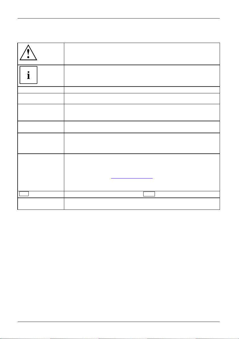
Notational conventions
Pay particular attention to text marked with this symbol. Failure to observe
these warnings could pose a risk to health, damage the device or lead
to loss of data. The warra nty will be invalidated if the device becomes
defective through failure to observe these warnings.
Indicates important informa
tion for the proper use of the device.
►
This font
This font
This font
"This font"
Key
This font
Indicates an activity that must be performed
Indicates a result
indicates data entered
the command line, e .g.
start a program (star
indicates information that is displayed on the screen by a program, e.g.:
Installation is complete.
indicates
• terms and texts used in a software interface, e.g.: Click on Save
• names of programs or files, e.g. Windows or setup.exe.
indicates
• cross-references to anot her section, e.g. "Safety information"
• cross-references to an external source, e.g. a web address: For more
information, go to "
• Names of CDs, DVDs and titles or designations for other materials,
e.g.: "CD/DVD Drivers & Utilities" or "Safety/Regulations" manual
indicates a key on the keyboard, e.g:
indicates terms and texts that are emphasised or highlighted, e.g.: Do
not switch off the device
using the keyboard in a program dialogue or at
your password (Name123) or a command used to
t.exe)
http://ts.fujitsu.com"
F10
8 Fujitsu Technology Solutions
Page 13
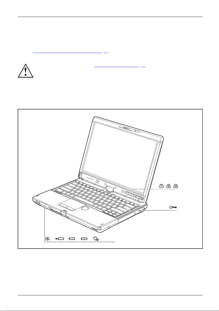
Ports and controls
Ports and controls
This chapter presents the individual hardware components of your device. It gives you
an overview of the device’s indicators and connections. Please familiarise yourse lf with
these components before you start to work with the device.
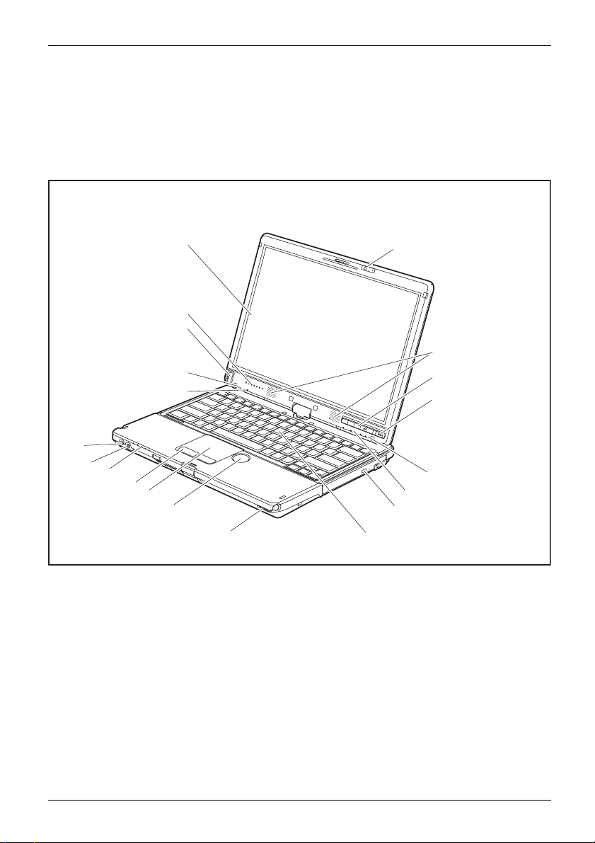
Notebook open
1
15
14
8
13
17
16
5
11
10
12
9
1 = LCD screen
2 = WebCam 2
3 = Tablet buttons
4 = ON/OF
5 = Status indicators
6 = Louds
7 = Keyboard
8=Micr
9 = ON/OFF switch for wireless components
mega pixel (* optional)
Fswitch
peakers
ophone
2
5
5
7
10 = Touchpad
11 = Touchpa
12 = ScrollWheel
13 = Ambie
14 = Fingerprint sensor
15 = Scrol
16 = Microphone jack
17 = Head
d buttons
nt light sensor
l sensor
phone port
6
3
4
8
Fujitsu Technology Solutions 9
Page 14
Ports and controls
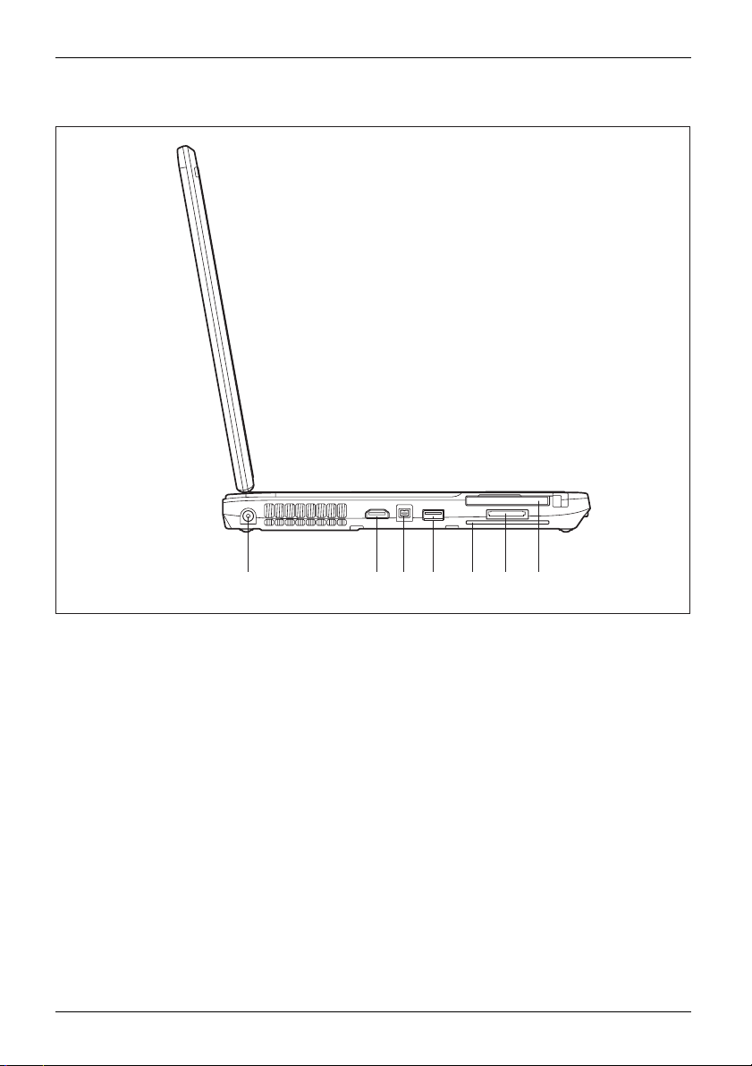
Left side
1 2 3 4 5 6 7
1 = DC input connector (DC IN)
2 = HDMI port
3 = FireWire port
4 = USB port (USB 3.0)
10 Fujitsu Technology Solutions
5 = SmartCard reader
6 = Memory card slot
7 = ExpressCard slot
Page 15
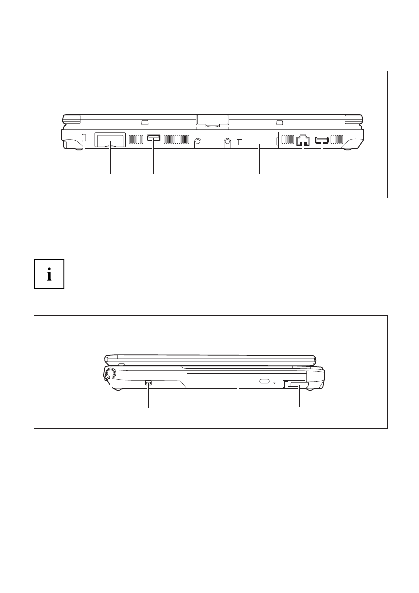
Rear
Ports and controls
1 2 3 4 5 6
1 = Security Lock device
2 = SIM card slot or modem connection
(depending on the device)
3=USBport(USB2.0)
The SIM card slot and VGA monitor port are protected by covers.
Right side
21
1=Penslot
2 = Attachment eye for the pen cord
4 = VGA monitor port
5 = LAN port
6 = USB port with c harging function (USB
2.0, Anytime USB charge)
3 4
3 = Module b
4 = Eject lever for module bay
ay with optical drive
Fujitsu Technology Solutions 11
Page 16
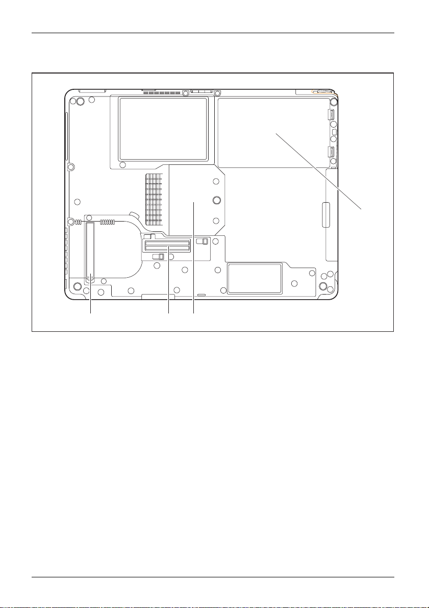
Ports and controls
Bottom
123
4
1 = Ventilation slot cover
2 = Port for port replicator
12 Fujitsu Technology Solutions
3 = Memory service compartment
4 = Rechargeable battery
Page 17
Important notes
ImportantnotesNotes
Safety notes
SafetynotesNotes
This chapter contains essential safety information which must be followed
when working with your notebook. Other notes also provide useful information
which will help you with your notebook.
Please follow the safety notes provided in the "Safety/Regulations" manual
as well as the safety notes given below.
Please pay special attention to the sections in the manual marked
with the symbol on the left.
When connecting and disconnecting cables, observe the relevant
notes in this operating ma nual.
Read the information on the ambient conditions in the "
Page 123 and "First-time setup of your device", Page 16 before preparing your
notebook for use and sw itching it on for the first time.
When cleaning the device, please observe the relevant notes in the
section "
Pay attention to the additional safety notes for devices with radio components
provided in the "Safety/Regulations" manual.
Please refer to the notes in the chapter "
components during servicing", Page 105.
Cleaning the notebook", Page 15.
Important notes
Technical data",
Removing and installing
This notebook
equipment. I
please conta
complies with the relevant safety regulations for data processing
f you have questions about using your notebook in a particular area,
ct your sales outlet or our Hotline/Service Desk.
Additional safety notes for devices with radio components
Radiocomponent:WirelessLAN:Bluetooth,safetynotes
If a radio component (Wireless LAN, Bluetooth, UMTS) is integrated in your notebook, you
must be sure to observe the following safety notes when using your notebook:
• Switch off the radio components when you are in an aircraft or driving in a car.
• Switch off the radio c omponent s when you are in a hospital, an operating room or near a medical
electronics system. The transmitted radio waves can impair the opera tion of medical devices.
• Switch off the radio components when you let the device get near flammable
gases or into hazardous environments (e.g. petrol station, paintshops), as the
transmitted radio waves can cause an explosion or a fire.
For information on how to switch radio components on and off, see chapter
Switching the wireless components on and off", Page 68.
"
Fujitsu Technology Solutions 13
Page 18

Important notes
Energy saving
NotesEnergyEnergysaving
Switch the notebook off when it is not in use. Switch off external, connected devices if you
are not using them. If you use the energy saving functions, the notebook uses less energy.
You will then be able to work for longer before having to recharge the battery.
Energy efficiency is increased and the environmental impact is reduced.
You save money while protecting the environment.
Energy saving under Windows
► Make use of the power management features (see ""Using the power-management features",
Page 59").
Travelling with you
MobileoperationNotesTranspo rtationNotebook
Please observe the points listed below when travelling with your notebook.
rnotebook
Before you travel
► Back up important data stored on your hard disk.
NotebookTravel,notebook
► Switch off the radio component for data security reasons. With data traffic via a wireless
connection, it is also possible for unauthorised third parties to receive data.
Information on a ctivating data encryption is provided in the docum entation
for your radio component.
► If you wish to use your noteboo k during a flight, first check with the flight
attendants if it is OK to do so.
When travelling in other countries
► If you are travelling abroad, check that the mains adapter can be operated with the
local mains voltage. If this is not the case, obtain the appropriate mains adapter for
your notebook. Do not use any other voltage converter!
► Check whether the local mains voltage and the power cable are compatible. If this is
not the case, buy a power cable that matches the local conditions.
► Enquire with the corresponding govern m ent office of the country you will be
travelling in as to whether you may operate the radio component integrated in your
notebook there (see also "
CE marking", Page 127).
14 Fujitsu Technology Solutions
Page 19

Important notes
Notebook: transporting
Protect the notebook from severe shocks and extreme temperatures
(e.g. direct sunlight in a car).
► If your device has an optical drive, remove all data media (e.g. CD, DVD) from the drives.
TransportationNotebook
► Switch the notebook off.
► Unplug the mains adapter and all external devices from the power socket.
► Disconnect the mains adapter cable and the data cables for all extern al devices.
► Close the LCD screen.
► To protect against damaging jolts and bumps, use a notebook carrying
case to transport your notebook.
Cleaning the notebo
ok
Do not clean any interior parts yourself; leave this job to a service technician.
Only use cleaning products designed for computers. Normal household
cleaners and polishes can damage the markings on the keyboard and the
device, the paintwork or the notebook itself.
Ensure that no liquid enters the notebook.
The LCD screen very sensitive to scratches. Only clean the display
surface with a very soft, slightly damp cloth.
► Switch the notebook off.
display
CleaningNotesNotebookKeyboardTouchpadLCDscreenCrystalView
► In order to prevent accidentially switching the device on, remove the power cable from the mains
adaptor and remove the battery (see "
The surface c
been moiste
an be cleaned with a dry cloth. If particularly dirty, use a cloth which has
ned in mild domestic detergent and t hen carefully wrung out.
Removing and installing the battery", Page 52).
To clean the keyboard and the touchpad, if available, you can use disinfectant wipes.
Ensure that no liquid enters the device.
Fujitsu Technology Solutions 15
Page 20
First-time setup of your device
First-time setup of your devic
First-timesetu pGettingstarted
On delivery, the battery can be found in the battery compartment or in the accessories kit.
The battery must be charged if you want to operate your device using the battery.
When used on the move, the built-in battery provides the device with the necessary power. You
can increase the operating time by using the available energy-saving fu nctions.
For instructions on how to connect external devices (e.g. mouse, printer) to your
device, please refer to the operating manual for your device.
Unpacking and
► Unpack all the individual parts.
► Check your
Please read the chapter "Important notes", Page 13.
If your device is equipped with a Windows operating system, the necessary
hardware drivers and supplied software are already pre-installed.
Before you switch on the device f or the first time, connect it to the mains voltage
using the mains adapter, see "
adapter must be connected during the entire installation process.
A system test is performed when your device is first switched on. Various messages
can appear. The display may remain dark for a short time or may flicker.
Please follow the instructions on the screen.
NEVER switch off your device during the first-time setup process.
Mains adapter conn ecting", Page 17.Themains
checking the device
Should you discover any damage that occurred during transportation,
notify your local sales outlet immediately!
PackagingTransport
device for any visible damag e which may have occurred during transportation.
e
You may ne
16 Fujitsu Technology Solutions
ed the packaging in the future, if you need to transport your device.
Page 21
Selecting a location
SelectingalocationDeviceMainsadapter
Select a suitable location for the device before setting it up. Follow
the instructions below when doing so:
• Never place the device or the mains adapter on a heat-sensitive surface.
The surface could be damaged as a result.
• Never place the device on a soft surface (e.g. carpeting, upholstered furniture,
bed). This can block the air vents and cause overheating and damage.
• The underside of the device heats up during normal operation. Prolonged contact
with the skin may become unpleasant or even result in burns.
• Place the device on a stable, flat, non-slippery surface. Please note that the
rubber feet of the device may mark certain types of delicate surfaces.
• Keep other objects at least 100 mm away from the device and its
mains adapter to ensure adequate ventilation.
• Never cover the ventilation slots of the device.
• Do not expose the device to extreme environmental conditions. Protect
the device from dust, humidity, and heat.
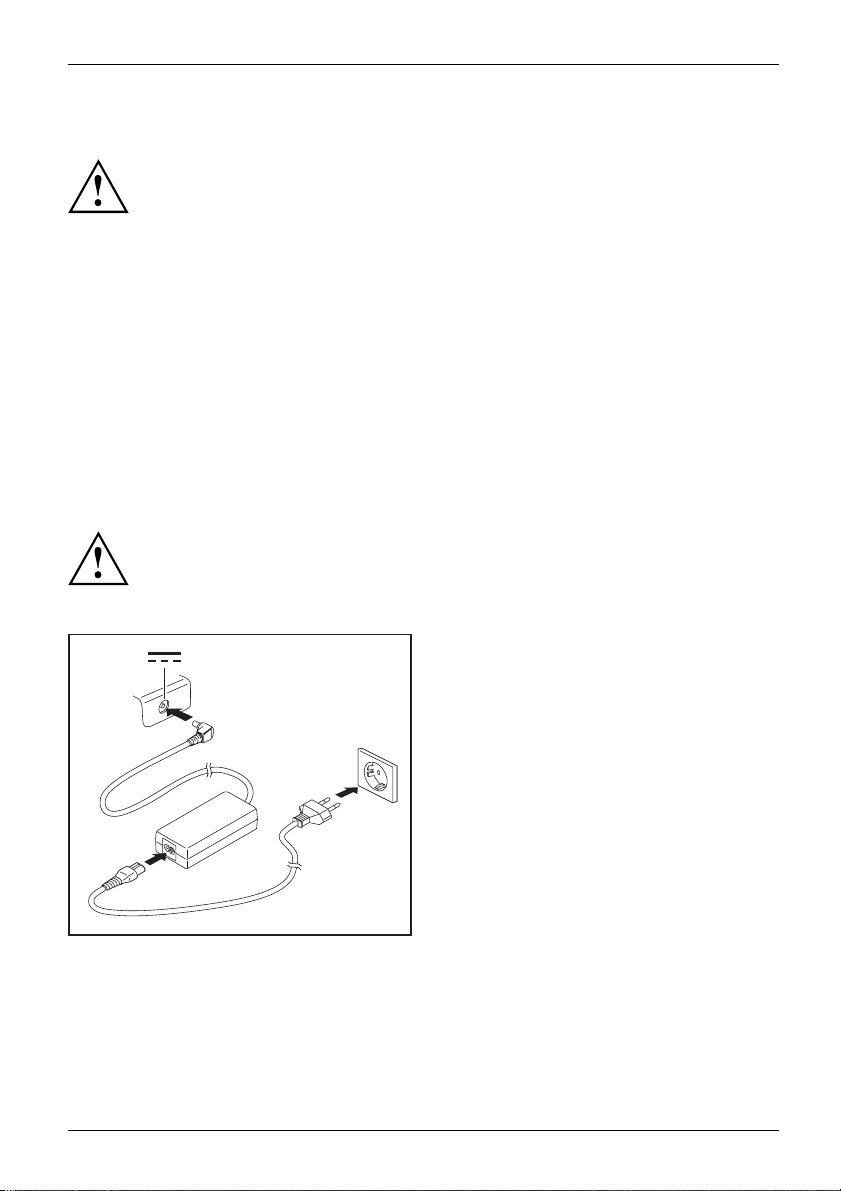
Mains adapter connecting
PreparingforoperationMainsadapter
Observe the safety notes in the enclosed "Safety/Regulations" manual.
The supplied p ower cable conforms to the requirements of the country in
which you purchased your device. Make sure that the power cable is approved
for use in the country in which you intend to use it.
First-time setup of your device
► Connect the power cable (1) to the
mains a dapter.
► Plug the mains cable (2) into a mains outlet.
► Connect the mains adapter cable (3) to
3
the DC jack (DC IN) of the device.
2
1
Fujitsu Technology Solutions 17
Page 22
First-time setup of your device
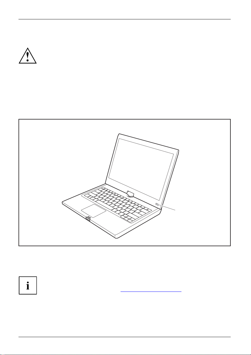
Switching on the device for the first time
Switchingonforthefirsttime
On devices with ON/OFF switch for wireless components: Slide the ON/OFF switch
for wireless components to the ON position before switching on the device.
When you switch on the device for the first time, the supplied software is
installed and configured. Because this procedure must not be interrupted,
you should set aside enough time for it to be fully completed and connect
the device to the mains using the mains adapter.
During the installation process, DO NOT restart the d evice unless
you are requested to do so!
To make it easier to use y
is p re-installed on th
► Slide the ON/OFF switch (1) to the right to switch on the notebook.
The ON/OFF switch returns automatically to its original position.
► During installation, follow the instructions on screen.
our device for the first time, the operating system
e hard disk.
1
If a Windows operating system is installed on your device, you will find more
information on the system and drivers, help programmes, updates, manuals etc.
on the device or on the Internet at "
18 Fujitsu Technology Solutions
http://ts.fujitsu.com/support".
Page 23
Working with the notebook
Working with the notebook
Notebook,operationNotebook
This chapter describes the basics for operating your notebook. Please read the chapte r
entitled "
devices such as a mouse and a printer to the notebook.
Status indicators
StatusindicatorsSymbols
The status indicators provide information about the status of the power supply,
the drives and the keyboard functions etc.
Connecting external devices", Page 97 for instructions on how to connect
Please refer to the notes in "Important notes", Page 13.
Fujitsu Technology Solutions 19
Page 24
Working with the notebook
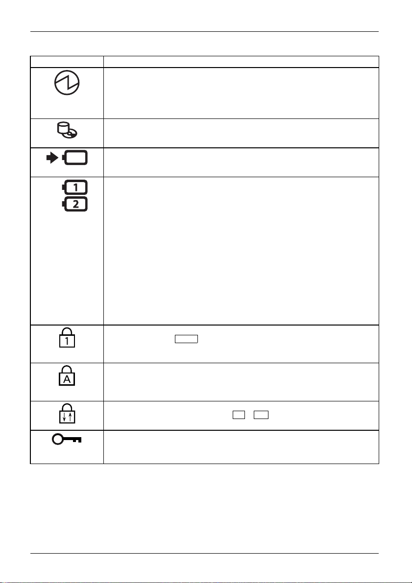
Status displays Description
Power-on indicator
• Indicator is illuminated: The notebook is switched on.
• Indicator flashes: The notebook is in sleep mode (Save-to-RAM).
• The indicator is not illuminated: The notebook is switched off or in
Save-to-Disk mode.
Drive indicator
Indicator is illuminated: The hard disk drive or the CD/DVD in the optical drive
of the notebook is being accessed.
Battery charging indicator
The battery charging indicator shows whether a battery is installed and being
charged.
Battery indicator
This description applies to both batteries.
The battery indicator shows the state of charge of the installed battery.
• The indicator light is green: the battery is between 50% and 100%
charged.
• The indicator is lit orange: The battery is between 13 % and 49 %
charged.
• The indicator is lit red: The battery is between 0 % and 12 % charged.
• The indicator flashes orange: The battery state of charge is being
checked (for four seconds after battery installation).
• The indicator flashes red: T he battery is faulty.
• The indicator is not lit: There is no battery installed.
Note: if you use batteries with a capacity of 5800 m Ah or 6200 mAh, you can
also check the charge status on the battery itself.
Num Lock indicator
Indicator is lit: The
keypad is activated. You ca n output the characters indicated on the upper
right of the keys.
Caps Lock
Indicato
as upperc
printed
Scroll Lock indicator
Indicator is lit: The key combination
that this key has varies between applications.
Lock Workstation indicator
The indicator is illuminated: The security functions of the Notebook have
locked your workstation.
Num
key has been pressed. The virtual numerical
indicator
r is lit: The Caps Lock key has been pressed. All letters will be output
ase letters. In the case of keys labelled several times, the character
on the upper left of the key will appear when that key is pressed.
Fn+Scr
has been pressed. The effect
20 Fujitsu Technology Solutions
Page 25
Opening the notebook
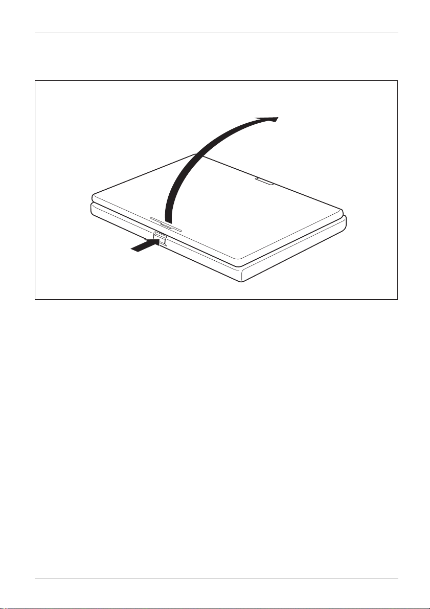
1
Working with the notebook
2
► Press the rel
Fujitsu Technology Solutions 21
ease button (1), and unfold the LCD screen upwards (2).
Page 26
Working with the notebook
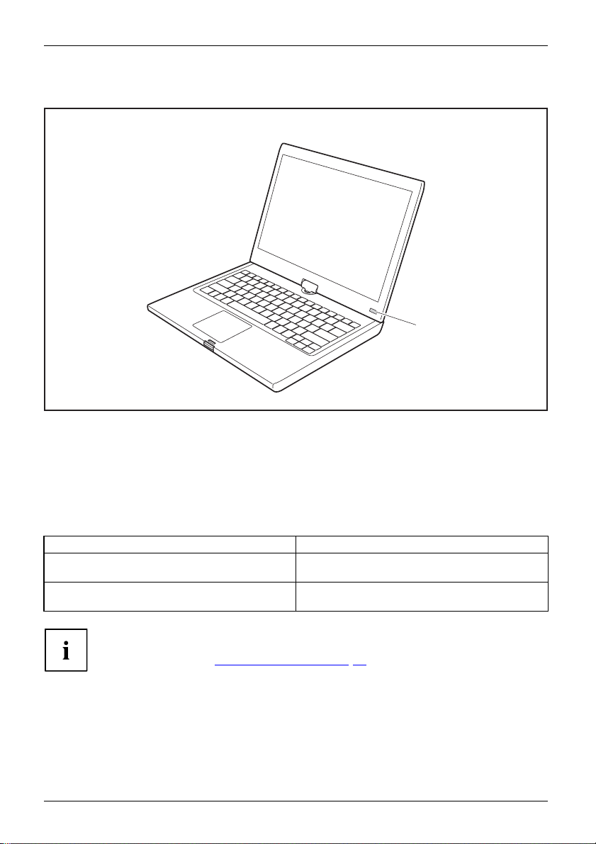
Switching on the notebook
Notebook:switchingonPower-onindicatorSuspend/Resumebutton
► Slide the ON/OFF switch (1) to the right to switch on the notebook.
The ON/OFF switch returns automatically to its original position.
The ON/OFF switch (1) lights up whenever the system is switched on.
1
Programming the ON/OFF switch
You can pro
Operating system Menu
Windows XP
Windows 7
22 Fujitsu Technology Solutions
gram the ON/OFF switch:
Start - (Settings) - Control Panel - Performance and
Maintenance - Power Options - Advanced
Start - (Settings) - Control Panel - System and
Security - Power Options
have assigned a password, you must enter this when requested to
If you
in order to start the operating system. Detailed information can be
do so,
d in the chapter "
foun
Security functions" , Page 76.
Page 27
Working with the notebook
Different ways to use your notebook
During your daily work, y ou can use your notebook as a tablet PC or as a notebook, just as you wish.
Note the direction of rotation in the following description! No guarantee claims
can be met for damage caused by turning in the wrong direction.
You must note that the display cannot be turned completely on its own axis!
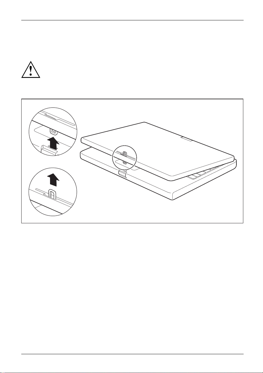
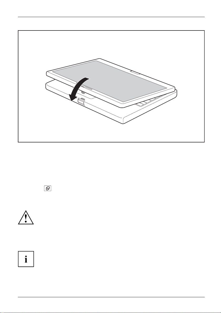
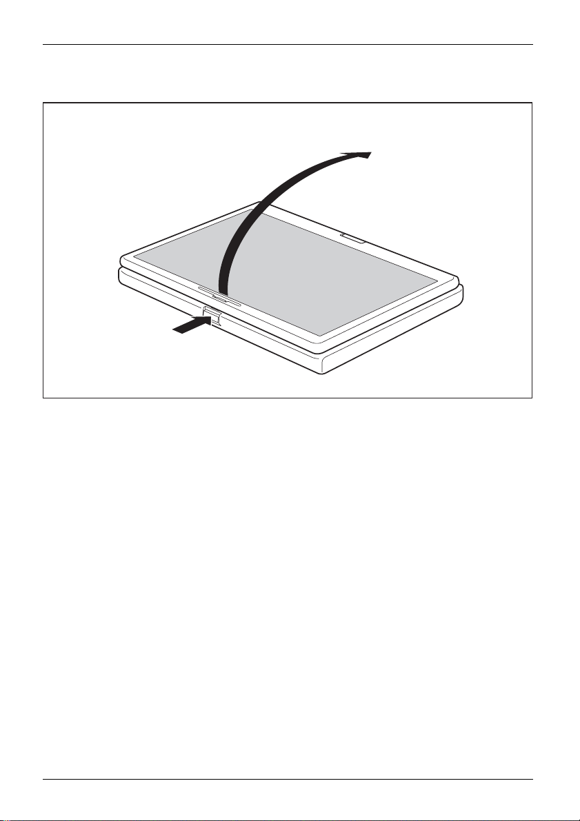
From notebook to Tablet PC
1
2
► Press the release button, and unfold the LCD screen upwards slightly.
► Rotate the hook from position 1 to position 2.
Fujitsu Technology Solutions 23
Page 28
Working with the notebook
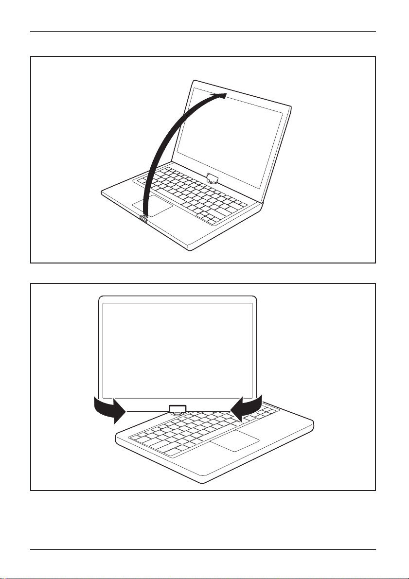
► Raise the screen into a vertical position.
► Hold the screen as low as possible on both sides. Turn the screen to the left or right in the direction
of the arrow. At first you will feel some slight resistance, then it will turn easily and without friction.
ate the display further until it has turned 180° and the hinge latches in.
► Rot
24 Fujitsu Technology Solutions
Page 29
Working with the notebook
► Now fold the screen down until the back of the screen is flat on top of
the keyboard and the hook latches in.
The screen is now secured in the tablet position.
Select displa
ientation
entation
ntation
Landscapeor
Portraitori
Displayorie
y orientation (portrait or landscape orientation)
You can choose to use either portrait or landscape orientation for the display. Press the
Tablet button
to switch between portrait and landscape orientation.
The display switches automatically to portrait layout when the device is used as a Tablet
PC and to landscape layout when it is used as a noteb ook.
Windows XP
You can change these settings in the Fujitsu menu or under Start –(Settings
–) Control Panel – Tablet and Pen Settings.
Windows 7
You can change these settings in the Fujitsu menu or under Start -(Settings -)
Control Panel - Hardware and Sound - Display - Settin gs.
Profiles for operating with various different screen modes can be selected via
the Fujitsu Tablet Control option in the Fujitsu menu. These profiles have preset
standard configurations that can be modified as desired.
These settings do not just affect the monitor settings on the Tablet PC, but
also any external monitors that may be connected.
Fujitsu Technology Solutions 25
Page 30
Working with the notebook
From Tablet PC to notebook
1
2
► Press the relea
► Open the display until it is in the vertica l position.
26 Fujitsu Technology Solutions
se button (1), and unfold the LCD screen upwards (2).
Page 31

Working with the notebook
Note the direction of rotation in the following description! No guarantee claims
can be met for damage caused by turning in the wrong direction.
The rotational direction indicator indicates the direction in w hich the screen
must be turned to get back to its initial position:
Fujitsu Technology Solutions 27
Page 32

Working with the notebook
► hold the screen as near to the bottom as possible on both sides and turn the screen in the
direction indicated by the rotational direction indicator. It will turn easily and without resistance.
► Turn or move the display further until it has turned 180° and the hinge latches in.
1
2
► To b
28 Fujitsu Technology Solutions
e able to shut the notebook again, rotate the hook from position (1) to position (2).
Page 33

Working with the notebook
Switching off the notebook
Notebook
► Close all applications and then shut down the operating system (please
see the "Operating System Manual").
► Slide the ON/OFF switch towards the right.
The O N/O FF switch returns automatically to its original position.
Closing the notebook
► Fold the LCD screen down onto the lower part of the notebook until you feel it lock into place.
Fujitsu Technology Solutions 29
Page 34

Working with the notebook
Language selection (Windows XP only)
LanguageselectionOperatingsystemla nguageLanguage
Your notebook can be supplied with the Windows XP Tablet PC Edition operating system
as a single or m ulti-langua ge version (according to your preference).
In the single language version, you are presented with two handwriting recognition input
areas, one for the operating system language and one for English.
In the multi-language version, you have the option of setting the language of the menu
texts and the keyboard as well as that of the handwriting recognition.
With the multi-language models, the default language set for the menu texts,
keyboard and handwriting recognition is English.
Selecting the language for menu texts
Selectthelanguage:formenutexts
► Click on Control Panel – Date, Time, Language and Regional Options – Language and Regional options.
► Select the desired language on the Regional Options tab.
Selecting the lan
and keyboard
Selectthelanguage:forhandwritingrecognitionandkeyboard
► Click on Control Panel – Date, Time, Language and Regional Options – Language and Regional options.
► Select the Languages tab.
► In th e Text services and input languages field, click on the Details button.
► In the next dialog window, sele ct the Settings register card and click the
Add buttonintheInstalled Services field.
► In the next dialog window, select the desired Input area schema.
You can now decide which functions (keyboard layout, handwriting recognition, etc.)
the selected input area schema is to be activated for.
► Mark the desired functions and then confirm your entries by clicking the OK button.
You will find further information in the Windows XP Tablet PC 2005 Edition operating system help.
guage for handwriting recognition
Handwriting recognition under Windows Vista
Handwriting recognition under Windows Vista currently supports the following languages:
English, German, French, Italian, Japanese, Korean, Chinese (traditional and
simplified), Dutch, Portuguese and Brazilian.
Handwriting recognition under Windows 7
writing recognition under Windows 7 currently supports the fo llowing languages:
Hand
ish, German, French, Italian, Japanese, Korean, Chinese (traditional and simplified), Dutch,
Engl
uguese, Spanish, Brazilian, Norwegian (Bokmål and Nynorsk), Swedish, Finnish, Danish,
Port
ish, Rumanian, Serbian (Cyrillic and Latin script), Catalan, Russian, Czech and Croatian.
Pol
30 Fujitsu Technology Solutions
Page 35

Working with the notebook
LCD screen
LCDscreenNotes
High-quality TFT displays are installed in notebooks from Fujitsu Technology Solutions GmbH. For
technical reasons, TFT monitors are manufactured for a specific resolution. An optimal, clear
picture can only be ensured with the correct resolution intended for the relevant TFT monitor. A
monitor resolution which differs from the specification can result in an unclear picture.
The screen resolution of the LCD monitor of your notebook is optimally set at the factory.
The standard of production techniques today cannot guarantee an absolutely fault-free screen
display. A few isolated constant lit or unlit pixels (picture e lements) may be present. The maximum
permitted number of pixels faults is stipulated in the international standard ISO 9241-3 (Class II).
Example:
A monitor with a resolution of 1280 x 800 has 1280 x 800 = 1024000 pixels. Each pixel consists of
three subpixels (red, green and blue), so there are almost 3 million subpixels in total. According to
ISO 9241-3 (class II), a maximum of 2 light and 2 dark pixels and an additional 5 light or 10 dark
subpixels or a corresponding mix may be defective (1 light subpixel co unts as 2 dark subpixels).
Pixel
Subpixel
Cluster A cluster contains two or more defective pixels or
A pixel consists of 3
blue. A pixel is the s
by complete functi
A subpixel is a sep
within a pixel tha
subpixels in a 5 x 5 pixel block.
subpixels, normally red, green and
mallest element that can be generated
onality of the display.
arately addressable internal structure
t enhances the pixel function.
Background li
TFT m onitors a
lighting can
set the brigh
Synchronis
For more in
under "Dis
ghting
re operated with background lighting. The luminosity of the background
decrease during the period of use of the notebook. However, you can
tness of your monitor individually.
ing the display on the LCD screen an d an external monitor
formation, please refer to the chapter "
play output, switch between".
Key combinations", Page 43
Ambient Light Sensor
If your notebook was shipped with the Windows 7 operating system, the screen brightness is
regulated by mea ns of the Ambient Light Sensor and depending on the respective light conditions.
This results in optimum readability and longer battery life at the same time.
Using
You can execute commands as follows:
• using the stylus pen (supplied with your device).
• using your finger (only with Dual Digitizer technology).
Fujitsu Technology Solutions 31
a device as a tablet PC
Page 36

Working with the notebook
Using fingers
You can execute certain commands by using your finger tip on the touchscreen of your device.
Everything which you can select or activate using your finger tip can also
be selected or activated using the stylus pen.
Calibrate the Dual Digitizer for finger-based operation of the device.
Please see the appropriate supplementary s heet for instructions on how to
calibrate your device to use Dual Digitizer Technology.
Please note: There are separate calibration programs available for calibrating
the stylus pe n and for calibrating finger-based operation. In each case, use the
calibration tool described in the supplementary sheet. Do not use the calibration
tool for the stylus pen to calibrate finger-based operation.
Selecting menu options (click with the left mouse button)
► Touch the menu option with your finger tip.
Starting programs (double-click with the left mouse button)
► Briefly touch the program icon twice with your finger tip.
Moving objects/windows (drag while holding the left mouse button pressed)
► Place your finger tip directly on the object/window, hold it pressed against the
screen and move the desired object/window.
Opening a context menu (click with the right m ouse button)
► Touch the desired item once with your finger tip.
The context menu appears.
Moving the cursor
► Place your finger tip on the screen and move your finger in the direction required.
Scrolling
► Use one finger to q uickly stroke across the screen upwards, downwards, left or right to
navigate through the document or to quickly page through the document.
Dragging
► Place your finger on an item on the screen and then move your finger without
removing it from the display; this will drag the item to another position. You can
also use this movement to page slowly through documents.
32 Fujitsu Technology Solutions
Page 37

Working with the notebook
Contracting and extending
► Touch the screen at two edges of an area with two fingers spread apart, then slide the fingers
together to make the area smaller. S prea d the fingers to make the area larger.
Rotating
► Touch two corners
counter-clockwi
se at the corners by using your fingers.
Enlarging a view
of a picture on the screen, then turn the picture clockwise or
► Put two fingers o
and move them a
n the touch screen
part.
Fujitsu Technology Solutions 33
Page 38

Working with the notebook
Reducing a view
Using the stylus pen
You can use the pen on
items and to navigat
handwriting recog
the pen. You can als
The notebook pen i
lost, regardless
it while travell
The notebook is
on the pen and on
of whether you use the notebook as a Tablet PC or as a notebook, or transport
ing. Always replace the pen in its slot when you are not using it.
your notebook as an electronic writing implement to select
e through menu options and programs. Programs that support
nition also allow you to write characters directly on the screen with
o use the pen as a drawing tool.
s retained securely in the pen slot. This ensures that the pen cannot be
supplied with a pen cord which you can attach to the eyelets
the no tebook.
► Put two fi ngers on the touch screen and
move them towards each other.
Only use the pe
that were not s
is w orn. The wa
While writin
display (e.
34 Fujitsu Technology Solutions
n provided with your notebook. Do not use substitute pen tips
pecially designed for your notebook. Replace the stylus tip if it
rranty does not cover a scratched scree n.
g, you sho uld take care not to scratch the surface of the
g. with a wristwatch or bracelet).
Page 39

Working with the notebook
The pen of your notebook is an electronic instrument which c an be damaged
if used incorrectly. Handle the pen with care.
The following list contains guidelines for proper pen handling:
• Do n ot gesture with the pen.
• Do not use the pen as a pointer.
• Never use the pen on any other surface than the screen of your notebook.
• Do not try to turn the thumb grip on the pen. The thumb grip is used to
place th e pen in its slot and to take it out of the slot.
• Never store the pen with the tip bearing the weight of the pen (e.g. with the tip down
in a pen holder). If the pen is stored with the tip pointing down, this may have
an adverse effect on the pen mechanism (particularly under high temperatures).
In this case the pen tip may react as though it is constantly being pressed down.
To avoid damage, the pen should be stored in the pen slot when not in use.
Thepencanbeinfluenced by electromagnetic fields (cursor quivers or
jumps). There may be a few areas on the screen where the cursor quivers
slightly in spite of pressing the pen down firmly.
The screen responds to entries made with the tip of the finger or the pen when the tip
of the finger or the pen is in direct contact with the screen.
You can use the pen to perform all the functions for which you would otherwise use a mouse.
In addition, you can conveniently delete hand-written pen entries using the pen.
Handling Mouse Pen
Selecting menu
Click with the left-hand mouse button.
Touch the menu entry with the pen tip.
entries
Starting progra m s Double c lick with the left-hand mouse
button.
Moving
objects/windows
Drag with the left-hand mouse button
held pressed.
Briefly touch the program icon twice
with the pen tip.
Place the pen tip directly on the
object/window. Hold the pen tip
pressed against the screen. Move the
desired object/window.
Opening a context
menu
Click with the right-hand mouse
button.
Touch the desired element with the
pen and leave the pen on the element
for a moment.
Moving the cursor
-
Place the pen tip directly on the
screen.
Fujitsu Technology Solutions 35
Page 40

Working with the notebook
Setting the pen
Operating system Menu
Windows XP You can access various pen settings under Fujitsu Pen Settings or
Windows 7
Tablet and Pen Settings in the Control Panel (for instance, the pressure
sensitivity).
Under Hardware and Sound – Pen and Input Devices in the Control Panel
you can change various settings for the pen (assignment and function of
the pen button).
Calibrating the pen
Before using the pen for the first time, you should calibrate it so that the cursor follows the
movements of the pen as accurately as possible. You should also always repeat the calibration
if the co-ordination betwe en the pen and cursor movement deteriorates.
Please note: There are separate calibration programs available for calibrating
the stylus pe n and for calibrating finger-based operation. In each case, use the
calibration tool described in the supplementary sheet. Do not use the calibration
tool for the stylus pen to calibrate finger-based operation.
Operating system Menu
Windows XP
Windows 7
To calibrate, run the Tablet and Pen Settings fun ction in the Control Panel.
You need to calibrate both portrait and landscape formats.
To calibrate, run the Hardware and Sound / Tablet PC Settings function in the
Control Panel. You need to calibrate both portrait and landscape formats.
36 Fujitsu Technology Solutions
Page 41

Working with the notebook
Replacing the pen tip
With use, the pen tip may become worn or may pick up foreign particles that can
scratch the screen. A damaged or worn tip may not move freely over the screen,
causing unpredictable results when using the pen.
If your pen exhibits these problems, you should replace the pen tip. To do this, use the supplied tool (1).
► To remove the tip, position the tip in the gap
between the two ends of the tool supplied.
► Pinch the two ends of the supplied tool
together so that the tip is firmly clasped,
then pull it fro m the barrel.
► Replace the tip of the pen with one of
the spare tips supplied with your pen.
Insert the flat end of the tip into the
barrel and exerting gentle pressure, push
it in until it is firmly in place.
1
If the tip is worn or damaged, discard it.
Installing a pen cord
Youshoulda
► Attach the e
► Attach the end of the pen cord with the larger loop to your notebook.
Fujitsu Technology Solutions 37
ttach the pen with a pen cord to prevent accidentally dropping or losing it.
nd of the pen cord with the smaller loop to your pen.
Page 42

Working with the notebook
Using the device as a notebook
Touchpad and touchpad buttons
Keep the touchpad clean. Protect it from dirt, liquids and grease.
TouchpadTouchpad
Do not use the touchpad if your fingers are dirty.
Do not rest heavy objects (e.g. books) on the touchpad or the touchpad buttons.
1
1 = Touchpad
2 = Touchpad buttons
2
The touchpad enables you to move the mouse pointer on the screen.
The touchpad buttons allow you to select and execute commands. They correspond
to the buttons on a conventional mouse.
You can use a key combination to disable the touchpad, to avoid accidentally moving
the pointer on the screen (see also "
Key combinations", Page 43).
Moving the pointer
► Move your fing
Touchpad
The pointer will move.
Selecting a
► Move the pointer to the item you wish to select.
Touchpad
► Ta p t h e t o
The item is selected.
er on the touchpad.
nitem
uchpad once or press the left button on ce.
Executi
► Move the pointer to the field you wish to select.
► Ta p t h e
ng commands
hpad
Touc
The command is executed.
touchpad twice or press the left button twice.
38 Fujitsu Technology Solutions
Page 43

Working with the notebook
Dragging items
► Select the desired item.
Touchpad
► Press and hold the left button and drag the item to the desired position
with the finger on the touchpad.
The item will be moved.
Switching the Touchpad on and off
You can switch the Touchpad on and off using a key combination,
Key combinations", Page 43.
see "
ScrollWheel
The ScrollWheel (1) is an innovative and extremely convenient control. The ScrollWheel
allows you to scroll up or down in the active window (e.g. on a website) or forwards and
backwards in a document with a single finger movement. It makes it very easy for you to
display and read websites, documents and the content of windows.
1
Fujitsu Technology Solutions 39
Page 44

Working with the notebook
Scrolling downwards or forwards
► Move the cursor to the window you
► Move your finger clockwise on the
Scrolling upwards or backwards
► Move the cursor to the
► Move your finger anticlockwise on
wishtoselect.
ScrollWheel.
You will scroll downwards or forwards.
window you
wishtoselect.
the ScrollWheel.
You will scroll upw
ards or backwards.
Back one page in Web browser
► Tap the centre of the ScrollWheel.
The Web browser returns to the
previous page displayed.
Keyboard
oard
rickeypad
rickeypad
ons
Keyb
Nume
Nume
Butt
40 Fujitsu Technology Solutions
board of your noteb ook is subject to continuous wear through normal
The key
he key markings are especially prone to wear. The key markings are
use. T
e to wear away over the life of the notebook.
liabl
Page 45

Working with the notebook
The keyboard has bee n designed to provide all the functions of an enhanced keyboard.
Some enhanced keyboard functions are mapped with key combinations.
The following description of keys refers to Windows. Additional functions supported by the keys
are described in the relevant manuals supplied with your application programs.
The figure below shows how to access the different characters on keys with overlaid functions.
The example applies when the Caps Lock key has no t been activated.
The illustrations shown below may differ from your actual device.
Num
+
=
0
=
0
}
}
=
0
=
}
0
+
=
0
}
}
Alt Gr
Fujitsu Technology Solutions 41
Page 46

Working with the notebook
Key Description
Backspace key
The Backspace key deletes the character to the left of the cursor.
BackspaceBackspace
Tab key
The Tab key moves the cursor to
Tabkey
the next tab stop.
Enter key (return)
The Enter key terminates
is executed when you pres
EnterkeyReturnEnterLinefeed
a command line. The command you have entered
s this key.
Caps Lock key
The Caps Lock key activates the Cap s Lock mode, and the corresponding
icon is displayed in the Windows information area. In Caps Lock mode, all
of the characters you type appear in upper case. In the case of overlay
keys, the character printed on the upper left of the key will appear when
that key is pressed. To cancel the Caps Lock function, simply press the
Caps Lock key again.
ShiftkeyCapsLock
Shift key
The Shift key ca
keys, the chara
keyispressed.
ShiftkeyShift
uses uppercase characters to appear. In the case of overlay
cter printed on the upper left of the key appears when that
Fn button
Fn
The
"
Key combina
Fnkey
key enabl
es the special functions indicated on overlay keys (see
tions", Page 43).
Cursor keys
The cursor
left, or ri
CursorkeysCursorcontrolkeys
keys move the cursor in the direction of the arrow, i.e. up, d o wn,
ght.
Start key
The Start
Startkey
key opens the Windows Start menu.
Menu key
The Menu key invokes the menu for the marked item.
42 Fujitsu Technology Solutions
Page 47

Working with the notebook
Virtual numeric keypad
NumerickeypadVirtualnumerickeypadNumLock
To provide the convenience of a numeric keypad, your keyboard is equipped with a virtual
numeric keypad. The special keys of the virtual numeric keypad are recognisable by the numbers
and symbols printed in the upper right corner of each key. If you have switched on the virtual
numeric keypad, you can output the characters shown on the upper right of the keys.
The keyboard layout shown below may differ from your actual device.
1 = Valid characters when the
key is not activated
r information about the status indicators can be found in chapter "
Furthe
Num
2 = Valid characters when the
is activated
Status indicators", Page 19.
Num
Country and keyboard settings
If you want to change the c oun try and keyboard settings, proceed as follows:
► Enter the settings by clicking Start – (Settings) – Control Panel – Time, Regional and Language Options.
Key combinations
The key combinations described below apply when using Microsoft Windows
operating systems. Some of the following key combinations may not function in
other operating systems or with certain device drivers.
Key combinations are entered as follows:
► Press the first key in the combination and keep it pressed.
► While holding the first key down, press the other key or keys in the combination.
Fujitsu Technology Solutions 43
Page 48

Working with the notebook
Combination Description
Switching the loudspeakers on/
This key combination switches t
off.
off
he integrated loudsp eakers on and
Enable/disable touchpad
This key combination enables
and disables the touchpad.
Decrease screen brightness
This key combination decreases the brightness of the screen.
Increase screen brightness
This key combination increases the brightness of the screen.
Decrease volume
This key combination reduces the volume of the internal
loudspeakers.
Increase volume
This key combination increases the volume of the internal
loudspeakers.
Toggle output screen
screen
Fn+F10Toggleoutput
Use this key combination to select which screen(s) is/are used for
display if an external monitor is connected.
Screen output is possible:
• only on the notebook’s LCD screen
• only on the external monitor
• on the notebook’s LCD screen and the external monitor at the
same time.
Press the key combination several times to switch through all
possible settings.
It is possible to display video on two screens simultaneously,
regardless of what type and number of external screen is connected.
If you have connected two external monitors to the port replicator,
the following display outputs are possible:
• only on the notebook’s LCD screen
• only on the external monitor (analogue)
• at the same time on the L CD screen (digital)
• at the same time on the notebook’s LCD screen and on the
external monitor (analogue)
You cannot use the key combination to switch output at the same
time to both external monitors on the Port Replicator.
44 Fujitsu Technology Solutions
Page 49

Working with the notebook
Combination Description
Ctrl
C
+
Halt current o peration
This key combination can be used to halt an operation instantly
without clearing the keyboard buffer.
Back tab
This key combination moves the cursor back to the previous tab
stop.
Tablet buttons
Your notebook has five multifunction tablet buttons. You can navigate on the screen with a
simple press of a button, call preset applications or ones that you have set yourself.
B
2
3
1
A
The tablet buttons have different uses in different modes.
You can also program each of them individually, see "
the tablet buttons", Page 49.
4
ENT
Programming
Fujitsu Technology Solutions 45
Page 50

Working with the notebook
Basic functions when the device has booted
Button Basic function
1
Scroll down
You scroll down in your document with this key.
A
B
EN
2
3
4
T
Scroll up
You scroll up in your document with this key.
Change screen orientati
WhenyoupresstheOrien
changes from portrait (
When you would like to
use the portrait orie
When accessing spre
orientation.
Open Fujitsu menu
Pressing this tablet button twice in quick succession will bring up the Fujitsu menu
on your screen. The Fujitsu menu is used to change certain system settings.
If you press this tablet button when the device is in sleep mode or is switched off,
the battery charge indicator appears. You can check the current battery charge
status without starting the operating system.
The battery LED indicates the battery charge status.
Log on to the system or open the Windows Task Manager
If you hold this tablet button down fo r two seconds, you can log back on to the
system again:
• after system startup
• after a system lock
• when returning from pow er management
After log-on, pressing the tablet button for two se con ds launches the Windows Task
Manager or – in the network – opens the security window.
on
tation button, the orientation of the screen display
vertical) to landscape (ho rizontal) or vice versa.
use the Tablet PC as an eBook, for example, you would
ntation.
adsheets, you would more typically use a landscape
46 Fujitsu Technology Solutions
Page 51

Working with the notebook
Functions when the security system is active
If you have assigned a s upervisor password and/or user password, you can enter
this via the tablet buttons when starting your device.
Button Security functions
1
Security button 1 to enter the password.
A
B
EN
2
3
4
T
Security button 2 to enter
Security button 3 to enter the password.
Security button 4 to enter the password.
Security button 1 to confirm the entered password.
Detailed information on how to use the security functions is contained in Section
Using the security function of the tablet keys", Page 95.
"
the password.
Fujitsu Technology Solutions 47
Page 52

Working with the notebook
Functions during Windows log-on
When the Windows log-on dialog is displayed, the tablet buttons provide special functions:
Button Function
1
Tab ke y.
A
B
EN
2
3
4
T
Enter key.
Change screen orientation
When you press the Orientation button, the orientation of the screen display
changes from portrait (vertical) to landscape (horizontal) or vice versa.
When you would like to use the Tablet PC as an eBook, for example, you would
use the portrait orientation.
When accessing spreadsheets, you would more typically use a landscape
orientation.
Fn
key, see "Key combinations " , Page 49.
Logontothesys
If you hold thi
system again:
• after system
• after a system lock
• when return
After log-on, pressing the tablet button for two se con ds launches the Windows Task
Manager or – in the network – opens the security window.
tem or open the Windows Task Manager
s tablet button down for two seconds, you can log back on to the
startup
ing from power management
48 Fujitsu Technology Solutions
Page 53

Key combinations
Key combinations cannot be changed.
You c a n find information on programming the tablet buttons in "
the tablet buttons", Page 49.
Shortcut Meaning
4
1
A
+
4
2
B
+
4
3
+
Starting predefined application A
This button allows yo u to start a previously defined application.
By default, the button is preconfigured to start the Launch Center application.
Starting predefined application B
This button allows yo u to start a previously defined application.
By default, the button is preconfigured to start the Windows Journal
application.
Toggle outpu t screen
Use this key combination to select which screen(s) is/are used for display if
an external monitor is connected.
Screen output is possible:
• Monitor(s) connected to the notebook:
internal LCD screen -> only CRT (VGA) - > internal LCD screen +
CRT (VGA) -> only HDMI -> internal LCD screen + HDMI -> back to
beginning (internal LCD screen)
• Monitor(s) connected to the Port Replicator:
internal LCD screen -> only CRT (VGA) -> internal LCD screen + CRT
(VGA) -> only DVI > internal LCD screen + DVI -> only DisplayPort ->
internal LCD screen + DisplayPort -> only HDMI -> internal LCD screen
+ HDMI -> back to beginning (internal LCD screen)
Working with the notebook
Programming
The tablet b
the two but
them both at the same time. After pressing the
short time (2 to 3 seconds) to press the second button.
Program
You can program the tablet buttons to open a specific application or execute
a s pecific function when pressed.
Proceed as follows:
► In Control Panel, select the option to manage the settings for the tablet buttons and pen.
► Follo
Fujitsu Technology Solutions 49
ming the tablet buttons
w the instructions on the screen and program the tablet buttons as you require.
utton
tons for a sho rtcut one after the other instead of needin g to press
has a practical delay function: This allows you to press
tablet button, you have a
Page 54

Working with the notebook
Webcam
Webcam
Depending on the device variant, a WebCam may be integrated in your notebook.
The WebCam has its own statu
Depending on the software
record video clips or take
• The picture quality depe
s indicator. T he indicator lights up when the WebCam is switched on.
used, you can use your Webcam to take pictures,
part in web chats.
nds on the lighting conditions an d the software being used.
• You can only operate the webcam with a particular application (e.g. an Internet telephony
program or a video conferencing program which supports a webcam).
• When using the webcam th
e notebook support must not wobble.
• The webcam automatica lly adjusts itself to the current light level. For this reason
the LCD screen may flicker while the light level is adjusted.
Further information on using the webcam and on the additional settings
which are possible for your webcam can be found in the h elp function
of the program which uses the webcam.
If you wish to carry out a function test with your webcam, you can use the
corresponding test software available at "
http://ts.fujitsu.com/support/".
Rechargeable battery
RechargeablebatteryBatteryLife,batteryRechargeablebatteryRechargeablebattery
When not plugged into a mains socket, the notebook runs on its built-in battery. You
can increase the life of the battery by caring for the battery properly. The average
battery life is a round 500 charge/discharge cycles.
You can extend the battery life by taking advantage of the available energy saving functions.
50 Fujitsu Technology Solutions
Page 55

Working with the notebook
Charging, caring for and maintaining the ba ttery
BatteryBattery
The notebook battery can only be charged, when the ambient temperature
is between 5°C and max. 35°C.
You can charge the battery by connecting the notebook to the mains adapter
Mains adapter connecting", Page 17).
(see "
If the battery is running low you will hear a warning alarm. If you do not connect the mains adapter
within five minutes of the warning alarm described abo ve, your notebook will automatically switch off.
monitoring the battery charging level
BatteryBatterystatusmeter
Windows also has a "Battery status meter" in the taskbar for monitoring the battery capacity. When
you place the mouse pointer on the battery symbol, the system displays the battery status.
The battery capacity can be monitored using an indicator which shows the current state
of charge. Use the following menu to enable this feature:
Operating system Menu
Windows XP
Windows 7
Start – (Settings) – Control panel–Power options
Start – (Settings) – Control panel – Mobile PC –
Power options
The indicator is then displayed in the task bar as a battery symbol. When you place the
mouse pointer on the battery symbol, the system displays the battery state of cha rge. Please
refer to the Help facility of the operating system for more information.
Battery storage
ge,battery
city,battery
BatteryBatterySelf-dischar
Chargingcapa
Keep the battery pack between 0°C and +30°C. The lower the temperature at which
the batteries are stored, the lower the rate of self-discharge.
If you will be storing batteries for a longer period (longer than two months),
the battery charge level should be approx. 30 %. To prevent exhaust ive
discharge which would permanently damage the battery, check the level
of charge of the battery at regular intervals.
To be able to make use of the optimal chargi n g capacity of the batteries, the battery
should be completely discharged and then fully recharged.
If you do not use the batteries for long periods, remove the m from the
notebook. Never store the batteries in the device.
Fujitsu Technology Solutions 51
Page 56

Working with the notebook
Removing and insta lling the batte ry
Only use rechargeable batteries approved by Fujitsu Technology
Solutions for your notebook.
Never use force when fitting or removing a battery.
Make sure that no foreign bodies get into the battery connections.
Never store a battery fo r longer periods in the discharged state. This
can make it impossible to recharge.
Removing a battery
2
1
1
► Press in the two catches (1), keep them pressed and lift the battery out
of the battery compartment (2).
52 Fujitsu Technology Solutions
Page 57

Installing a battery
Working with the notebook
1
2
► Position the batt
► Push the battery into the battery c om partment until it locks into position (2).
ery at the edge of the casing (1).
Fujitsu Technology Solutions 53
Page 58

Working with the notebook
Batteries with a capacity of 5800 mAh or 6200 mAh
With these batteries you can check the state of charge directly on t he battery itself.
► Remove the battery (s ee "
a
► Press the test key (1).
The LED (a) li
LED indicato
Green The battery is between 50 % and 100 %
Orange The batter
Red The batte
LED not l
ghts up in one of the following colours:
r
it
Removing and installing the battery", Page 52).
1
State of charge
charged.
y is between 13 % and 49 % charged.
ry is charged somewhere between 1
% and 12 %.
The battery is fully discharged.
54 Fujitsu Technology Solutions
Page 59

Working with the notebook
Module
ModulebayModules
The design of your notebook enables the flexible use of notebook batteries and drives. The
following modules can be operated in the module bay of your notebook:
• Second battery
• Second hard disk drive
• Optical drive
• Empty plug-in unit (save weight)
Only use modules designed for your notebook.
Do not use force when installing or removing the module.
Make sure that no foreign objects enter the module bay.
You can swap modules during operation. This means you do not
need to switch off the notebook.
To replace a module, simply click on the corresponding icon in the
task bar and then on Exit or Select - Exit.
The module can now be removed without any further actions being necessary.
Removing a module
1
1
2
ModuleDriveWeigh t Saver
► Slide the release lever in the direction of the arrow (1).
► Now pull
the module out of the module bay.
Fujitsu Technology Solutions 55
Page 60

Working with the notebook
Installing a module
► Place the module into the module bay so that the contacts enter first.
► Push the module into the module bay until you feel it locking into place.
Optical drive
Opticaldrive
Handling data carriers
Handling
Observe the following guidelines when handling data carriers:
• Avoid touching the surface of a data carrier. Only handle data carriers by their edges.
• Always store data carriers in their cases. This will protect the data carrier against
• Protect your data carriers against dust, mechanical vibrations and direct sunlight.
• Avoid storing a data carrier in areas subject to high temperatures or humidity.
You may use both 8-cm and 12-cm data carriers in the opt ical drive.
When using a data carrier of lesser quality, vibrations and reading errors may occur.
This product contains a light emitting diode, classified in accordance with IEC
8251:1993: LASER CLASS 1, and must therefore not be opened.
being c overed in dust, scratched or damaged in any other way.
CD/DVD indicator
indicator
CD/DVD
The CD/DVD indicator flashes when a data carrier is inserted. The indicator goes out when
the drive is ready for reading. The indicator lights up when the drive is being accessed.
You m a y only remove the data carrier w hen the indicator is unlit.
If the CD/DVD indicator does not go out after a data carrier has been inserted, but
instead continues to flash, this means that the drive cannot access the data carrier.
Either the data carrier is damaged or dirty or y ou are using a data
carrier that the drive cannot read.
56 Fujitsu Technology Solutions
Page 61

Inserting or removing a data carrier
InsertingRemoving
The notebook must be switched on.
► Push the insert/eject button (1).
The drive tray will open.
► Gently pull the drive tray (2) completely out.
2
1
► Place the data carrier in the drive tray with
the printed side facing upwards.
or
► Remove a data carrier that has
► Push in the drive tray until you
Working with the notebook
been inserted.
feel it lock into place.
Manual removal (emergency removal)
CD/DVD:ManualremovalofdatacarrierEmergencyremovalofdatacarrier
In the e vent o
f a power failure or damage to the drive, you can remove the data carrier manually.
► Switch your
notebook off.
► Push a pen or a piece of wire (such as a
paperclip) firmly into the opening (1).
The drive t
the drive t
ray is ejected. You can now pull
ray (2) out of the drive.
2
1
Fujitsu Technology Solutions 57
Page 62

Working with the notebook
Removing and replacing the casing cover (ventilation slot cover) to get rid of dust
To ensure optimum cooling of your notebook’s components, you should clean
the ventilation slots of the cooling fan after prolonged use.
This ensures optimum fan performance. Best cleaning results are achieved
using a small hand-held vacuum cleaner.
Ifnecessary,useadrybrushtoremovedustfromtheventilationslots.
Do not use any cleaning liquids! Ensure that liquid does not enter the device.
To avoid the device overheating, do not remove the ventilation slot
cover when the device is switched on.
► Prepare for removal, see chapter "
2
1
1
Preparing to remove components", Page 106.
► Keep the locking tabs of the ventilation
slot cover pressed down (1).
► Lift the ventilation slot cover out
of the bay (2).
► Clean the dust chamber with a dry b rush.
► Insert the ventilation slot cover into slot (1)
and ensure that you feel it click into place.
► Complete the removal, see chapter
Finishing component removal", Page 112.
"
58 Fujitsu Technology Solutions
Page 63

Working with the notebook
Using the power-management features
PowerPowerBattery
The notebook uses less power when the available power-management features are used. You
will then be able to work longer when using the battery before having to recharge it.
Power efficiency is increased and environmental pollution reduced. By
choosing the best power options, you can make significant savings a nd
at the same time help protect the environment.
When you close the LCD screen, depending on the setting in Windows, the
notebook automatically enters a power saving mode.
We recommend the following settings:
Function On external power On battery power
Turn off monitor After 10 minutes After 5 minutes
Turn off hard disk(s) After 15 minutes After 10 minutes
Energy saving (S3) After 20 minutes After 15 minutes
Hibernate mode (S
4)
After 1 hour After 30 minutes
► Select the power ma
nagement functions in your Control Panel.
► Select the Screen Saver in your Control Panel.
or
► Right-click on the desktop. Switch on the screen saver by clicking Personalization –
Change screen saver.
If you need further information about an option, you can get help with most
F1
settings by pressing
to open the Microsoft Help.
When the notebook is in power-saving mode, the following must be remembered:
During power saving mode, open files are held in the main memory
orinaswapfile on the hard disk.
Never turn off your notebook while it is in a power saving mode. If the built-in battery is
nearly empty, close the open files and do not go into power saving mode.
If you do not intend to use your notebook for a long period of time:
► Exit power saving mode if necessary via the mouse or keyboard or by switching on the
notebook.
► Close all opened programs and completely shut down the notebook.
Fujitsu Technology Solutions 59
Page 64

Working with the notebook
Memory cards
Slot
Your notebook is equipped with an integrated memory card reader.
Observe the manufacturer ’s instructions when handling the memory cards.
Memorycard
Supported formats
It supports the following formats:
• Secure Digital (SD
•MemoryStick
• Memory Stick Pro
Inserting the memory card
TM
card)
► Carefully slide the memory card into the
slot. The label should be facing upward. Do
not apply excessive force, as otherwise the
delicate contact surfaces could be damaged.
Memorycard
Depending on the particular type
used, the memory card may protrude
slightly from the slot.
60 Fujitsu Technology Solutions
Page 65

Working with the notebook
Removing the memory card
Memorycard
In order to protect your data, always follow th e correct procedure
for removing the card outlined below.
You can stop the memory card via the corresponding icon in the task bar:
► Left-click on the icon.
► Select the card you want to stop and remove.
► Press the Enter key.
Wait for the dialogue box which tells you that it is now safe to remove the memory card.
► On devices with card locking: Press
on the storage card (1).
Memorycard
The storage card is released and
can now be removed.
► Pull the storage card out of the slot (2).
1
2
Fujitsu Technology Solutions 61
Page 66

Working with the notebook
ExpressCards
SlotExpressCar d
An ExpressCard slot enables operation of an ExpressCard/34 or ExpressCard/54.
Consult the documentation supplied by the ExpressCard’s manufacturer
and follow the instructions provided.
Never use force when installing or removing an ExpressCard.
Make sure that no foreign objects enter the ExpressCard slot.
Inserting the card
Keep the placeholder for the slot in a safe place. When you remove the card again you
must reinstall the placeholder. This prevents foreign bo dies from getting into the slot.
► If the eject button (1) is recessed, press it
once so that it disengages. Now press the
eject button again so that the placeholder
protrudes slightly from the notebook.
1
2
► Pullthecardplac
eholder out of the slot (2).
► Insert the card into the slot guide with
the connection contacts first.
► Gently push the card into the s lo t either
until it will go no further or you feel it
engage. Do not use excessive force.
Depending on the type, the card may
protrude slightly from the slot.
Please s
62 Fujitsu Technology Solutions
ee the documentation relating to the card for driver installation instructions.
Page 67

Working with the notebook
Removing the card
Always remove the card according to the rules described below, to
ensure that none of your data is lost.
You can stop the card using the corresponding icon in the task bar:
► Left click on the icon to safely remove hardware, located in the taskbar.
► Select the card you want to stop and remove.
► Press the "Enter" key.
Wait for the dialog box which tells you that it is now safe to remove the card.
► If the eject button is lowered, you must
first cause the eject button to release
from the notebook casing. To do this,
press the eject button until it pops out.
1
2
Press the eject button (1) so that the card
protrudes a little from the notebook.
► Pull the card out of the slot (2).
► Insert the card placeholder into the
slot guide.
► Carefully s lid
card as far as it
Do not use exce
e the placeholder for the
willgointotheslot.
ssive force.
Loudspeakers and microphones
MicrophoneLoudspeakersBassloudspeaker (subwoofer)Volumecontrol
Information on the exact position of the speakers and microphone can be
found in "
Please refer to chapter "
and also enabling/disabling the loudspeakers using key combinations.
Fujitsu Technology Solutions 63
Ports and controls", Page 9.
Key combi nations", P age 43 for information on setting the volume
If you attach an external microphone, the built-in microphone is disabled.
When you connect headphones or external speakers, the built-in speakers are disabled.
Information on connecting headphones and a microphone can be found
in "
Connecting external devices", Page 97.
Page 68

Working with the notebook
Integrated 56k modem
56kmodemModem
The integrated 56k modem supports all data communication applications, such as:
• Modem opera tion: High-speed downloads at up to 56,000 bit/s (V.9x).
• Fax operation: Transmitting and receiving at up to 14,400 bit/s
• Simple software-based country adaptations
The modem complies with the EU Directive 91/263/EEC (Telecommunications terminal equipment
directive) and has been checked in agreement with the guideline TBR-21.
The modem can be operated in the following countries:
Multifrequency (MFC) dialling: Belgium, Denmark, Germany, Finland, France,
Greece, Great Britain, Holland, Ireland, Iceland, Italy, Luxembourg, Norway,
Austria, Portugal, Sweden, Switzerland and Spain.
Pulse dialling: Belgium, France, H olland and Italy.
Also in: Poland, Slovenia, South Africa and Hungary.
Whether or not your device has a 56k modem depends on the device
configuration you have ordered.
Downward-compatible to V.34 m odems.
64 Fujitsu Technology Solutions
Page 69

Working with the notebook
Connecting notebook modem to telephone wall socket
If you use a modem, incompatibilities with the local telephone system may result.
This may result in poor performance, or the modem may not work at all.
Check whether you need a country-specific telephone adapter (available
as an optional accessory).
The modem cable and the country-specific telephone adapte r are not included
in delivery. You can order these as an option.
Please note that the telephone line is busy and that you cannot use your
telephone if the modem cable is plugged into the telephone wall socket. Pull the
modem cable out of the telephone socket after you have finished your interne t
session or the fax mode and reconnect the telephone cable.
► Connect the modem cable to the modem
port of the notebook (1).
Modem
► Plug the modem cable (
4
1
3
2
country-specificte
► Connect the modem cable to your
telephone wall socket (4).
2) into the
lephone adapter (3).
SIM card
Whether yo
have order
A SIM Card (Subscriber Identity Module) is a chip card which is inserted in a mobile telephone or
notebook and, together with an integrated UMTS module, enables access to a mobile radio network.
When handling SIM cards, follow the instructions supplied by the provider.
Fujitsu Technology Solutions 65
ur device has a SIM card slot depends on whether you
ed UMTS functionality.
Page 70

Working with the notebook
Inserting the SIM card
► Prepare for insertion of the SIM card, see chapter "Preparing to remove components", Page 1 06.
► Open the protective rubber cover of the SIM card slot.
Do not pull on the SIM card lock! The lock could break off otherwise. Always
slide the lock in the direction of the arrow as shown.
► Slide the SIM card lock (a) in the
a
1
3
2
direction of the arrow (1).
The clip (a) controls the power supply for
the UMTS module. The UMTS module is
switched off while the clip is open.
► Slide the SIM card as shown into
slot (2) until it engages.
► Slide the SIM card lock (a) in the
direction of the arrow (3).
► Close the protective rubber cover of the SIM card slot.
► Complete the i
66 Fujitsu Technology Solutions
nsertion process, see chapter "
Finishing componen t removal", Page 112.
Page 71

Working with the notebook
Removing a SIM card
► Prepare for removal of the SIM card, see chapter "Preparing to remove components", Page 106.
► Open the protective rubber cover of the SIM card slot.
Do not pull on the SIM card lock! The lock could break off otherwise. Always
slide the lock in the direction of the arrow as shown.
► Slide the SIM card lock (a) in the
a
1
3
2
direction of the arrow (1).
► Press on the edge of the SIM card so
that it pops out of the s lot slightly.
► Pull the SIM card out of the slot in the
direction of the arrow (2).
► Slide the SIM card lock (a) in the
direction of the arrow (3).
► Close the protective rubber cover of
the SIM card slot.
► Complete the removal, see chapter "
Finishing co mponent removal", Page 112.
Optional Wireless LAN / BlueTooth / UMTS wireless components
The installation of radio components not approved by Fujitsu Technology Solutions
will invalidate the certifications issued for this device.
Depending on the device configuration you ordered, your device will be
equipped with Wireless LAN, Bluetooth and / or UMTS.
Fujitsu Technology Solutions 67
Page 72

Working with the notebook
Switching the wireless components on and off
Before switching on your device for the first time, the on/off switch for
radio components must be in the "ON" position.
► Slide the ON/OFF switch into the "ON"
position to activate the radio components.
WirelessLANWi relessLANBluetoothBluetooth
or
► Slide the ON/OFF switch to the
"OFF" position to deactivate the
radio components.
If you switch off the radio components, the wireless LAN transmission unit (antenna)
and, if present, the Bluetooth and UMTS module will also be switched off.
You can enable and disable the installed radio components individually
using the WirelessSelector programme
You can also deactivate the wireless components individually in the BIOS Setup.
For this to occur, you must either not have assigned a supervisor password or if a
supervisor password has been assigned, you must know this password.
Pay attention to the additional safety notes for devices with radio components
provided in the "Safety/Regulations" manual.
Details on using Wireless LAN can be found in the online help system
included in the Wireless LAN software.
You ca n find more information on how to use Bluetooth on the CD you
received with your Bluetooth software.
You can obtain more information on UMTS from your service provider.
Setting up WLAN access
• Requirement: A WLAN must be available and you must have the
corresponding access information.
Information on configuring the WLAN access can be found in the
documentation for your operating system.
68 Fujitsu Technology Solutions
Page 73

Working with the notebook
Access via UMTS
If you ordered an integrated UMTS module with your system, you can enjoy optimum
reception and maximum energy efficiency without awkward cables or antennas. The
optional UMTS module is ready for use straight away.
If you did not order a UMTS module, you can purchase the accessories for UMTS reception
from your retailer or you r Fujitsu Technology Solutions dealer.
You wi l l find information on establishing the connection with the UMTS network
in the documentation for the hardware used.
You can connect your device with the Internet via UMTS. To do this, u se one
of the following types of connection:
• a USB dongle (a USB stick with your mobile phone provider’s SIM card)
• UMTS ExpressCard (for inserting in the E xpressCard slot of your device)
• mobile end-device (e.g. mobile phone with Bluetooth or cable connection)
UMTS antenna
► To improve the UMTS
swing out the UMTS a
direction of the a
UMTSUMTS
1
reception,
ntenna in the
rrow (1).
Fujitsu Technology Solutions 69
Page 74

Working with the notebook
Ethernet and LAN
EthernetLAN
The internal network module of your notebook supports Ethernet LAN. You can use it to
establish a connection to a local network (LAN = Local Area Network).
► Connect the network cable to the L A N
port of the notebook (1).
► Connect the network cable to your
network connection (2).
1
2
Your network administrator can help you to configure and use the LAN connections.
The network cable is not included in the delivery scope. This type of
cable can be obtained from a specialist dealer.
70 Fujitsu Technology Solutions
Page 75

Working with the notebook
Your Port Replicator (optional)
Your Port Replicator is a device that enables you to quickly connect your notebook
to your peripherals, such as a monitor, printer etc.
The features offered by the Port Replicator include stand ard ports for
monitor, audio, mouse and keyboard.
You need only dock the notebook in order to use your peripheral devices.
Ports on the Port Replic
PortReplicatorPorts
1
9
ator
2
2
3
4
5
8
7
6
11
10
1=DVIport
2=USBports
3 = DisplayPort
4 = VGA monitor port
5 = LAN port
6 = Headphone port
Fujitsu Technology Solutions 71
7 = Security Lock device
8 = DC input connector (DC IN)
9 = Connector on the Port Replicator for the
docking port on the bottom of the notebook
10 = Unlocking lever
11 = ON/OFF switch
Page 76

Working with the notebook
Setting up the port replicator
Select a suitable location for the port replicator before setting it up.
Follow the instructions below when doing so:
• Never place the port replicator on a soft surface (e.g. carpeting, upholstered furniture, bed).
This can block the air vents of the notebook and cause overheating and damage .
• Place the port replicator on a stable, flat and non-slip surface. Please note that the
port replicator’s rubber feet may mark certain types of surface.
• Never place the port replicato r and the mains adapter on a heat-sensitive surface.
• Do not expose the port replicator to extreme environmental conditions.
Protect the port replicator from dust, humidity and heat.
72 Fujitsu Technology Solutions
Page 77

Working with the notebook
Connect the notebook to the p ort replicator
► Disconnect the mains adapt er cable from the DC socket (DC IN) of the notebook.
1
3
2
► Position the notebook on the port replicator in such a way that the docking connector on the
underside of the notebook is aligned with the docking connector of the port replicator as shown.
► Press down on the notebook’s rear corners so that it locks into position.
► Connect the mains adapter cable to the DC jack (DC IN) of the port replicator (1).
► Connect the power cable to the mains adapter (2).
► Plug the power cable into the mains socket (3).
Fujitsu Technology Solutions 73
Page 78

Working with the notebook
Switching on the notebook via the port replicator
► Press the ON/OFF switch on the port replicator to switch the notebook on.
Switching off notebook via Port Replicator
► Close all applications and shut dow n your operating system (please refer
to the manual for the operating system).
If the notebook cannot be shut down properly, press the ON/OFF button
on the Port Replicator for approx. four seconds. The notebook will switch
off. Any unsaved data may however be lost.
74 Fujitsu Technology Solutions
Page 79

Working with the notebook
Disconnecting the notebook from the port replicator
Windows XP
Problems may occur if the notebook is removed from the port replicator
during operation. We recommend that you switch off the notebook beforehand
or use the Windows function Start – Undock.
Windows Vista / Windows 7
Problems may occur if the notebook is removed from the port replicator during
operation. We recommend that you switch off the notebook beforehand or use
the Windows function Start (arrow icon) – Undock.
2
1
► Pull the r
► Pick up the notebook (2).
Fujitsu Technology Solutions 75
elease button in the direction of the arrow (1).
Page 80

Security functions
Security functions
Securityfunctions
Your notebook has several security features that you can use to secure your
system from unauthorised access.
This chapter explains how to use each function, and what the benefits are.
Please remember that in some cases, for example, forgetting your password,
you may be locked out and unable to access your data. Therefore,
please note the following information:
• Make regular backups to external data carriers such as external hard
drives, CDs, DVDs or Blu-ray D iscs.
• Some security functio
of the passwords and ke
If you forget your passwords you will need to contact the our Service
Desk. Deletion or resetting of passwords is not covered by your warranty
and a charge will be made for assistance.
ns need you to choose passwords. Make a note
ep them in a safe place.
76 Fujitsu Technology Solutions
Page 81

Brief overview of security functions
Detailed information about the security equipment of your device can be found
in the "Professional Notebook" manual, on the "Drivers & Utilities" CD/DVD
or on our website at "
http://ts.fujitsu.com/support/".
Security functions
Security functions Type of protection
Security Lock
Fingerprint sensor (depending
on the device)
BIOS password protection Password protection for BIOS
Boot from removab
Owner Information Overlay service desk or owner
System Lock The BIOS and the system can
SmartCard r
dependent
Trusted Platform Module
(device dependent)
)
le media
eader (device
Mechanical Fit and lock the Kensingto
Biometric
Setup, operating system a nd
hard disk with supervisor and
user password. The passwords
consist of a maximum of eight
alphanumeric characters.
Prevents unauthorised booting
of an operating system from
external media (e.g. USB stick,
USB CD-ROM drive etc.).
information during the boot
process.
only be started with SmartCard
and PIN.
PIN and Smar
for operat
Identification and authentication
of the notebook
tCard protection
ing system
Preparation
Lock Cable (accessory).
Install the supplied fing erprint
software.
Specify at least one supervisor
password in the BIOS Setup
and activate the passw ord
protection for the operating
system and hard disk as
desired.
In the B IOS Setup,
Security menu and
option Boot from
Media.
In the B IOS Setup, go to the
Security menu and edit the
option Owner Information.
Initialise the SmartCard in the
BIOS.
To use the Sm
functions
(or other s
Define a supervisor password
in the BIO S Setup and enable
the TPM (Security Chip).
Removable
artCard reader
, install the supplied
uitable) software.
n
go to the
edit the
Fujitsu Technology Solutions 77
Page 82

Security functions
Configuring the fingerprint sensor
FingerprintsensorFingerprintsensor
The fingerprint sensor can record an image of a fingerprint. With additional fingerprint
software, this image can be processed and used instead of a password.
► You m ust install the fingerprint software
in order to be able to use the
fingerprint sensor (1).
1
Using the Security Lock
Your device comes with a Security Lock device for the Kensington Lock Cable. You can
use the Kensington Lock Cable, a sturdy st eel cable, to help protect your notebook from
theft. The Kensington Lock Cable is available as an accessory.
► Fit the Kensington Lock Cable on the
device on your notebook.
UsingtheKensingtonLockCableSecurityLockM ec hanicalbackupAnti-theftprotecti on
Attach another Kensington Lock Cable to your Port Replicator to protect
your Port Replicator from theft as well.
78 Fujitsu Technology Solutions
Page 83

Security functions
Configuring password protection in BIOS Setup Utility
Before using the various options for password protection in the BIOS Setup utility
to increase data security, please observe the following:
Make a note of the passwords and keep them in a safe place. If you forget your
supervisor password you will not be able to access your notebook. Passwords are
not covered by your warranty and a charge will be made for assistance.
Passwordprotection
Your password can be up to
No distinction is made be
Protecting BIOS Setup Utility (supervisor and user password)
If you have opened these opera ting instructions on the screen, we recommend that
you print out the following instructions. Because you cannot call the instructions
onto the scree n while you are setting up the password.
BIOSSetupUtility
You prevent unauthorised use of the BIOS Setup Utility with both the supervisor and the user
password. The supervisor passw ord gives you access to all functions o f the BIOS Setup
Utility, w hile the u ser password only provides some of the functions. You can only set a
user passwo rd if a supervisor password has already been assigned.
Please refer to the ""Settings in BIOS Setup Utility", Page 113 section for a
description of how to call up and operate the BIOS Setup Utility.
eight characters long and contain letters and numbers.
tween uppercase and lowercase.
Setting supervisor and user password
► Start the BIOS Setup Utility and go to the Security menu.
► Select the Set Supervisor Password field and press the Enter key.
With Enter new Password: you are asked to enter a password.
► Enter the password and press the Enter key.
Confirm new Password requires you to confirm the password.
► Enter the password again and press the Enter key.
Changes have been saved is a confirmation that the new password has been saved.
► To set the user password, select Set User Password and proceed exactly as
when configuring the supervisor password.
If you do not want to change any other settings, y ou can exit BIOS Setup Utility.
► In the Exit menu, select the option Save Changes & Exit.
► Select Ye s and press the Enter key.
PasswordSupervisorpasswordUserpassword
The notebook will be rebooted and the new password will come into effect. It will now be
necessary to first enter your supervisor or user password in order to open the BIOS Setup Utility.
Please note that the user password only provides access to a few of the BIOS settings.
Fujitsu Technology Solutions 79
Page 84

Security functions
Changing the supervisor or user password
You can only change the supervisor password when you have logged into the
BIOS Setup Utility with the s upervisor password.
PasswordSupervisorpasswordUserpassword
► Call the BIOS S etup Utility andgototheSecurity menu.
► When changing the password, proceed exactly as for password assignment.
Removing passwords
To remove a password (without setting a new passwo rd) perform the following steps:
PasswordSupervisorpasswordUserpassword
► Start the BIOS Setup Utility and go to the Security menu.
► Highlight the Set Supervisor Password or Set User Password field and press the Enter key.
You will be requested to enter the current password by the Enter Current Password prompt.
You will be requested to e nter a new password by the Enter New Password prompt.
► Press the Enter key twice.
► In the Exit menu, select the option Save Changes & Exit.
► Select Ye s and press the Enter key.
The notebook will now reboot with the password removed.
Removing the supervisor password simultaneously deactivates the user password.
Password protection for booting of t he operating system
With the superv
section "
prevent booti
Operatingsystem
isor password you have set in the BIOS Setup Utility (see
ng supervisor and user password", Page 79), you can also
Setti
ng of the operating system.
Activating system protection
► Start the BIOS Setup Utility and go to the Security menu.
Operatingsystem
► Select the Password on Boot option and press the Enter key.
► Select the desired option (Disabled, First Boot or Every Boot) and press the Ente r key
► Select the Save Changes & Exit option under Exit.
The notebook will reboot. You will be prompted to enter your password (the supervisor password).
Deactivating system protection
► Start the BIOS Setup Utility and go to the Security menu.
Operatingsystem
► Select the Password on Boot option and press the Enter key.
► Select the Disabled option and press the Enter key.
If you do n o t want to change any other settings, you can exit BIOS Setup Utility.
► Select the Save Changes & Exit option under Exit.
The notebook will reboot. The system is no longer password-protected.
80 Fujitsu Technology Solutions
Page 85

Security functions
Password protection for the hard disk
Passwordprotection:
The had disk password prevents unauthorised access to the hard disk drives
and is checked internally each time the system is booted. The condition for this
is that you have assigned at least the supervisor password.
Activating hard disk protection
► Call up the BIOS Setup and select the Security me nu.
If you have not assigned BIOS passwords yet, define the supervisor and the user
password now, if desired (see "
► Mark the Hard Disk Security field and press the Enter key.
► In the Drive0 area mark the Set Master P assword field and press the Enter key.
Enter new Password then appears and you a re asked to enter a password.
► Enter the password and press the Enter key.
Confirm new Password requires you to confirm the password.
► Enter the password again and press the Enter key.
Setup Notice: Changes have been saved is displayed to confirm that t he
new password has been saved.
► To assign the password for the second hard disk (Drive1), go to the Drive1 area and
select the field Set Master Password, then proceed in exactly the same way as for
setting up the password for the first hard disk (Drive0).
The field Password Entry on Boot is set to Enabled by default. You can exit the BIOS
Setup once you have finished changing the settings.
► From the Exit menu, choose the option Exit Saving Changes.
► Press the Enter key and select Yes .
The notebook reboots and your hard disk is now protected with a password. The system
will ask you to enter the password when the notebook is restarted again.
Security functions", Page 76).
Deactivating hard disk protection
To cancel a password without setting a new one, proceed as follows:
► Call up the BIOS Setup and select the Security me nu.
► Mark the Hard Disk Security field and press the Enter key.
► In the Drive0 area mark the Set Master P assword field and press the Enter key.
You will be initially requested to enter the old password by the E nter c urrent Password prompt.
You will then be requested to enter a new password by the Enter new P assword prompt.
► After entering the password, press the Enter key three times.
► From the Exit menu, choose the option Exit Saving Changes.
► Press the Enter key and select Yes .
The notebook reboots, and password protection for the hard disk is cancelled.
► To cancel the password for the second hard disk (Drive1), go to the Drive1 area
and select the field Set Master Password, then proceed in exactly the same way as
for cancelling the password for the first hard disk (Drive0).
Fujitsu Technology Solutions 81
Page 86

Security functions
SmartCard reader
Securityfunctions,Securityfunctions
SmartCards are not supplied as standard equipment. You can use all S martCards that comply with
the ISO stand ard 7816-1, -2 or -3. These SmartCards are available from various ma nufacturers.
With the appropriate software yo u can use your SmartCard as an alternative to password protection,
but also as a digital signature, for encrypting your e-mails or for home b anking.
We recommend that you always use two SmartCards. Always keep one of the SmartCards
in a safe place if you are carrying the other SmartCard with you.
In order to be able to take advantage of all the security features of your notebook, you
will need a CardOS SmartCard from Fujitsu Technology Solutions.
The SmartCard can only be used with a PIN, offering maximum protection even if
you lose the SmartCard. In order to maximise your security, the Ca rdO S SmartCard
is disabled if three incorrect attempts are made to enter the PIN.
When you use the CardOS SmartCard for the first time, you will either need to enter the
preset PIN "12345678" or the PIN given to you by your systems administrator.
Inserting the SmartCard
Do not use force when inserting and removing the SmartCard.
Make sure that foreign objects do not fall into the SmartCard reader.
► Slide the Smar
reader with th
some variants
82 Fujitsu Technology Solutions
tCard into the SmartCard
e chip facing upwards (on
it faces down) and to the front.
Page 87

Security functions
SmartCard SystemLock (optional)
With SystemLock enabled, the device can only be started using a n initialised SmartCard (SICRYPT,
CardOS or Fujitsu) and a personal identification number (PIN). The SmartCard and PIN are
checked during system booting in the BIOS, i.e. before the operating s ystem is started.
SmartCard SystemLock
Install Single PC:
[Enter]
Install Group PC: [Enter]
Item Specific Help SmartCard SystemLock Not Installed
Installs the security
for this PC, and
creates a new
SystemLock Admin
SmartCard dedicated to
this PC.
SmartCard data will be
overwritten.
A correct SmartCard is
required for a
permanent installation
system
SmartCardSwitchingonthe
All new SmartCards have a preset PIN (Personal Identification Number)
and PUK (Personal Unblocking Key).
On SICRYPT and CardOS SmartCards, the value 12345678 is p reset
for the PIN and the PUK.
On Fujitsu cards, the value 0000 is preset for the PIN and the value
administrator is preset for the PUK. For security reasons, we recommend
that you change both PIN and PUK without fail.
Additional software (e.g. Smarty) is required so that the system can also check that
the correct SmartCard is inserted while the system is running.
For information on how to uninstall SystemLock, please refer to "Uninstall System Lock".
A system which was protected using SystemLock can no longer be released.
Always create a backup copy of the SmartCard which was u sed .
Fujitsu Technology Solutions 83
Page 88

Security functions
Access rights of SmartCards
SmartCardSmartCardSmartCard
A new SmartCard initially only has a preset PIN and PUK. Access rights and the customised
PIN and PUK are not assigned until the SmartCard is initialised. Th e SmartCard type
depends on the access rights assigned to the c ard, as described below:
• User SmartCard: starting the system, changing the P IN
• SuperUser SmartCard: starting the system, changes in BIOS Setup, changing the PIN
• Service SmartCard: changes in BIOS-Setup, operating system boot-up not possible
• Admin SmartCard: starting the system, changes in BIOS Setup, changing the PIN,
uninstalling SystemLock, initialising SmartCards, blocking SmartCards
The following table shows an overview of the rights granted with each type of
SmartCard when a PIN or PUK is entered:
User
SmartCard
SuperUser
SmartCard
Service
SmartCard
Admin
SmartCard
PIN PUK PIN PUK PIN PUK PIN PUK
Start-up system
Run BIOS Setup
Change own PIN
Unblocking own
xx x
xxx
xx xxx
x* x* x*
x
blocked SmartCard
Unblocking all blocked
x
SmartCards
Generating user cards
Uninstall SystemLock
x
x
* BIOS Setup setting (Unblock own SmartCard)
Usually t here is always one Admin SmartCard and at least one User or SuperUser
SmartCard that will allow a system to be operated.
84 Fujitsu Technology Solutions
Page 89

Security functions
SmartCard user groups
SmartCard
User groups can be set up using SystemLock. This enables several systems to be started with one
SmartCard. A user group consists of at least two systems. Ea ch user that is allowe d to start the
systems is provided with one SmartCard. The user can start any of the systems using this SmartCard.
Basic information on setting up user groups
When installing SystemLock,thefirst PC in the user group is set up as a "Single PC". The
Admin SmartCard generated during this process is used to set up the user group. SystemLock
sets up each additional device as a "Group PC" during installation. The existing Admin
SmartCard is inserted, information is read in and the device is added to the user group.
The Admin SmartCard determines which user group the device belongs to.
If you use FSC-CardOS SmartCards, SystemLock can be administered via the Windows
program "SystemLock Admin". "SystemLock Admin" allows you to conveniently manage
SystemLock at the op erating system level, create SystemLock Organisation Units and Groups,
generate SmartCards for these Organisation Units or Group s, assign access rights for user
cards at various levels and restore access rights using remote access. You can also change
the SmartCard’s PIN or PUK for yourself and othe r users and reactivate blocked cards.
For a detailed description, see the "SystemLock Admin" Help manual.
Select Syste m -
mode: F1
1
SmartCard
PC 1
2
AdminCard
PC1
PC1
Select System -
mode: F3
3
PC2
martCards or SuperUser SmartCards must still be generated using SystemLock so t hat
User S
can access the systems within the user group. Using a User SmartCard or SuperUser
users
tCard a user can log on to each system within the user group.
Smar
Admin Card
PC1
PC3
3
Admin Card
PC4
PC1
SelectSystem -
mode: F3
3
Admin Card
PC1
Fujitsu Technology Solutions 85
Page 90

Security functions
Installing Sys temLock
InstallingSystemLock
During initial installation, the first SmartCard becomes the Admin SmartCard. Together with
the PUK, it has all access rights, and should therefore be kept in a s afe place. It can only
be used by the authorised user (administrator), e.g. to initialise user cards.
You need an Admin SmartCard if you want to set up a user group. You use the
Admin SmartCard to add further systems to the user group.
Setting up the first system in a user group or a stand-alone
system for use with SystemLock
Usergroups
► Start the device and call up BIOS Setup.
► From the Security menu, choose the option SmartCard SystemLock.
The following SmartCard SystemLock menu will be displayed:
Security
SmartCard SystemLock Item Specific Help
SmartCard SystemLock Not Installed
Install Single PC [Enter]
Install Group PC [Enter]
Enter PIN: [ ]
► Insert a new SmartCard in the reader and press Enter.
Installs the security
from a SystemLock Admin
SmartCard into this PC
without modifying any
data on the SmartCard.
A correct SmartCard is
required for a
permanent installation.
86 Fujitsu Technology Solutions
Page 91

New SmartCards have a preset PUK (see above).
if you want to re-initialise a previously initialised SmartCard, you will need
to know the PUK which was assigned to it.
► Enter the PUK.
When the following appears:
• ACCESS DENIED = You have entered an invalid PUK. After six failed attempts,
the SmartCard will be blocked and can no longer be used.
► Enter a new PIN at the following prompt:
Enter new PIN:
Confirm new PIN:
A number with 4 to 8 digits is acceptable for the new PUK. For security
reasons, we recommend that you change the PUK for every SmartCard,
and use an 8-digit number each time.
► Re-enter the new PIN to confirm.
When the following
• PIN/PUK do not match = You have confirmed the PIN incorrectly. You will be
requested to re-enter the new PIN and reconfirm.
Please wait a few s
The following m
Setup Notice
appears:
econds after confirming the new PIN: SystemLock is being installed.
essage will be displayed if installation is successful:
Security functions
Changes have been saved
[Continue]
► Now press the Enter key. The SystemLock administration menu will be displayed:
Fujitsu Technology Solutions 87
Page 92

Security functions
Security
SmartCard SystemLock Item Specific Help
SmartCard SystemLock Installed
Uninstall: [Enter]
Allows to deactivate
The smartcard security.
BIOS Recovery: [Allowed]
SmartCard and Pin [Always required]
ATTENTION:
Always check the BIOS
SmartCard Initialization
Admin SmartCard [Enter]
SuperUser SmartCard: [Enter]
password settings after
uninstalling
SystemLock.
User SmartCard: [Enter]
Service SmartCard: [Enter]
NOTICE:
Reinstalling a SinglePC
SmartCard Configuration
Change PIN: [Enter]
implies re-initializing
all of your smartcards
Change PUK: [Enter]
Unblock SmartCard: [Enter]
► For security reasons, the preset PUK should always be changed before removing
the new Sma rtCard. To do this, under SmartCard Configuration, select the option
Change PUK, press the Enter key and input the new PUK.
► First enter the preset PUK.
Enter the PUK:
New SmartCards have a preset PUK (see above).
You will need to know the PUK assigned to the SmartC a rd if you want to
re-initialise a previously initialised SmartCard.
► Enter the PUK.
When the following appears:
• ACCESS DENIED = You have entered an invalid PUK. After six failed attempts,
the SmartCard will be blocked and can no longer be used.
► Enter the new PUK as follows.
Enter new PUK:
Confirm new PUK:
A number with 4 to 8 digits is acceptable for the new PUK. For security
reasons, we recommend that you change the PUK for every SmartCard,
and use an 8-digit number each time.
► Re-enter the new PUK to confirm.
When the following appears:
• PIN/PUK do not match = You have confirmed the PUK incorrectly. You will then
be requested to re-enter and reconfirm the new PUK.
unctionkey
unctionkey
unctionkey
unctionkey
unctionkey
functionkey
F5,f
F6,f
F7,f
F8,f
F9,f
F10,
Instructions on how to initialise an additional SmartCard can be found in Section
Carrying out administrator functions", Page 91.
"
88 Fujitsu Technology Solutions
Page 93

Security functions
► If you do not want to initialise any further SmartCards, press
Esc
and remove the Admin
SmartCard. NEVER write the PIN or PUK on the Sma rtCard under any circumstances!
Keep the SmartCard and PIN/PUK in a safe place and protect
them from unauthorised access.
Adding a system to a user group
SystemLock2
► Start the device.
► Call up BIOS Setup and select the SmartCard SystemLock page from the Security menu.
The following SmartCard SystemLock menu will be displayed:
Security
SmartCard SystemLock Item Specific Help
SmartCard SystemLock Not Installed
Install Single PC [Enter]
Install Group PC [Enter]
Enter PIN: [ ]
Installs the security
from a SystemLock Admin
SmartCard into this PC
without modifying any
data on the SmartCard.
A correct SmartCard is
required for a
permanent installation.
► Insert the A dmin SmartCard for the user group.
Enter PIN:
► Enter the PIN.
When the f
ollowing appears:
• ACCESS DENIED = You have confirmed the PIN incorrectly. You are then requested to
enter and confirm the new PIN again. After three failed attempts, the SmartCard will
be blocked and can then only b e activated again by entering the PUK.
ePUK:
Enter th
Fujitsu Technology Solutions 89
Page 94

Security functions
► Enter the PUK.
When the following appears:
• ACCESS DENIED = You have entered an invalid PUK. After six failed attempts,
the SmartCard will be blocked and can no longer be used.
Please wait a few seconds after entering the PIN and PUK: SystemLock is being installed.
The following message will be displayed if installation is successful:
Setup Notice
Changes have been saved
[Continue]
Now press the E nter key. The SystemLock administration menu will be displayed:
Security
SmartCard SystemLock Item Specific Help
SmartCard SystemLock Installed
Uninstall: [Enter]
BIOS Recovery: [Allowed]
SmartCard and Pin [Always required]
SmartCard Initialization
Admin SmartCard [Enter]
SuperUser SmartCard: [Enter]
User SmartCard: [Enter]
Service SmartCard: [Enter]
SmartCard Configuration
Change PIN: [Enter]
Change PUK: [Enter]
Unblock SmartCard: [Enter]
F5,functionkeyF6, functionkeyF8,function keyF9,function key
Allows to deactivate
The smartcard security.
ATTENTION:
Always check the BIOS
password settings after
uninstalling
SystemLock.
NOTICE:
Reinstalling a SinglePC
implies re-initializing
all of your smartcards
Generate a user card for the device as described in Section "Carrying out
administrator functions", Page 91.
► If you do not wan t to initialise any further SmartCards, press
Esc
remove th e Admin SmartCard.
and
90 Fujitsu Technology Solutions
Page 95

Security functions
Carrying out administrator functions
If you have an internal SmartCard reader, you can switch on the device by inserting the SmartCard.
If you switch on the device with the On/Off switch then the following message appears:
SystemLock
Insert a SmartCard.
Administratorfunctions
► Insert the Admin SmartCard. The following message will be displayed:
EnteryourPIN:
You can now select:
F2=Setup, F3=Change PIN, F4=Administration
► Press the
Enter the PUK:
► If you have entered the PUK correctly, you receive the following message:
PUK OK.
Initialize another Sm a r tCard or press ESC to abort?
F5=User, F6=SuperUser, F7=Admin, F8=Service, F9=Unblock SmartCard, F10=Uninstall
F5
Only allows system start-up, does not allow changes in BIO S Setup.
F6
Allows system start-up and changes in BIO S Setup.
F7
Allows generation of further Admin SmartCards.
F8
Only allows changes in BIOS Setup.
F9
Enables a new user PIN entry.
F10
Additional SmartCards should be produced either as Normal User SmartCards
("System") or as Exten ded User SmartCards ("System and Setup"). These
then have restricted access to the device.
► Press the desired function key. The following message will be displayed:
Remove the SmartCard.
► Remove the Admin SmartCard.
Insert a SmartCard.
F4
function key. The following message will be displayed:
: Normal User SmartCard ("System" access rights):
: Extended User SmartCard ("System and Setup" access rights):
: Admin SmartCard ("Admin" access rights):
: Service SmartC ard ("Service" access rights):
: Re-activate a blocked User SmartCard.
: Uninstalls SystemLock.
Keep the A dmin SmartCard in a safe place and protect it from unauthorised access.
Fujitsu Technology Solutions 91
Page 96

Security functions
► Insert the next SmartCard. It will be initialised as required.
The following message will be displayed:
Remove the SmartCard.
Always change the PIN and PUK for all furth er SmartCards. The PUK
is used to re-activate a blocke d SmartCard.
► Remove the User SmartCard and label it, e.g. with the name of the user. But NEVER
write the PIN on the SmartCard under any circumstances!
92 Fujitsu Technology Solutions
Page 97

Security functions
Remote Access Enabling –
Requirement:
The device is centrally administered as part of an Organisation Unit and is registered in a SystemLock
Admin database. The SmartCard used for the group installation must have been initialised beforehand
using the SystemLock Admin.EXE Windows program (see "
In order to enable "remote" access to a device for a user, or to grant one-time "remote"
access to a device for a guest or service technician, proceed as follows:
► Start the device.
The prompt to Insert a SmartCard will appear.
► Press the
The following dia
The user must then
inform them of th
The administrator then specifies the type of the once-only access rights:
User
access
Service
access
Admin
access
F4
key.
logue box will appear:
contact the administrator or the administration hotline and
e data and codes displayed .
The user can boot the system once.
The user has one-time access to the BIOS for service purposes, without
access to the SystemLock functions.
The user has a cces s to the BIOS and the SystemLock functions, e.g. for
activating the device when the associated SmartCard has been lost.
F4
SmartCard user groups", Page 85).
SmartCard SystemLock
Org Unit:
PC Group:
I-CODE 1:
I-CODE 2:
Company Department 1
Group 1
0123456789ABCDEF
0123456789ABCDEF
An a ctivation code will be generated that depends on the access rights granted;
this will be given to the user by the Hotline.
The user must now press the Enter key on the PC to be activated, enter the first half (Code
1) of the activation code and confirm t he entry by pressing Enter. The dialogue box for
entering the second half (Code 2) of the activation code will appear. If an incorrect entry
is made, there is no limit to the number of times the process can be repeated.
When all 32 characters of the activation code ha ve been co rrectly entered , the
device will b oot with the rights assigned by the administrator, in the same way
as if a corresponding SmartCard were inserted.
The activation code can only be used once to start the device; it immediately becomes
invalid when the device boots. If you wish to switch off the device and start it again
without your SmartCard, the procedure described above must be repeated each time.
Fujitsu Technology Solutions 93
Page 98

Security functions
Switch on the device using SystemLock
If you have an internal SmartCard reader, you can switch on the device by inserting the SmartCard.
If you switch on the device with the On/Off switch then the following message appears:
Insert a SmartCard.
SystemLock
► Insert your SmartCard.
Enter PIN:
► Enter your PIN.
When the following appears:
ACCESS DENIED = You have entered an incorrect PIN. A fter three failed attempts, the
SmartCard will be blocked and can only be enabled again by entering the PUK.
Depending on the rights assigned to your SmartCard, you can select the following
functions when this message is displayed on the screen:
F2=Setup, F3=Change PIN
If your SmartCard has the appropriate rights, you can:
F2,functionkeyF3, functionkey
F2
: start BIOS Setup.
F3
: change PIN.
If you do not select a function, the system will boot up.
Start B IOS Setup
F2
A SmartCard with the appropriate rights must be inserted (SuperUser, Service or Admin).
Changing PIN
It is possible to change the PIN for any initialised SmartCard.
► Press the function key
F3
.
► Enter the old PIN.
► Enter the new PIN.
A number with 4 to 8-digits is acceptable for the new PIN. For security
reasons, we recommend that you change the PIN for every SmartCard,
and use an 8-digit number each time.
► Confirm t
he new PIN.
Uninstall SystemLock
► Start the device.
Uninstalling
► Follow the instructions given in section "Carrying out administrator functions",
Page 91. Select "Uninstall" to uninstall SystemLock. You can now use the
device again without the need for a SmartCard.
94 Fujitsu Technology Solutions
Page 99

Error messages
Errormessages
In this chapter you will find the error messages which are generated by the
mainboard and the SmartCard reader.
Error Cause
Boot access denied
Check your
SmartCard
SmartCard reader
FA I L UR E
Non-authorised
SmartCard
SystemLock
installation
FA I L ED :
The SmartCard is
blocked.
Enter the PUK:
The SmartCard has no access rights to the system.
The SmartCard is either inserted incorrectly or it is not a suitable SystemLock
SmartCard.
An error has occurred on the serial port to the SmartCard reader. If this error
occurs frequently, the connection between the SmartCard reader and the
mainboard must be checked, or the SmartCard reader must be replaced.
While the error is present, access to the system is blocked.
The SmartCard cannot be used on this device. The SmartCard has been
configured for a different device.
An error occurred while installing SystemLock. Do not switch off the device,
insert the "BIOS Flash diskette" instead.
Perform a BIOS update and try th e installation process again.
You have exceeded the maximum allowed number of incorrect PIN entries.
The SmartCard is blocked. Enter the administrator PUK to re-activate the
SmartCard. You must then enter a new User PIN to restart the system.
Security functions
Using the secu
If you have allotted a supervisor and/or user password in the form of tablet key combinations as
described below, you can use the tablet keys to enter this when you start your device.
rity function of the tablet keys
Setting the Supervisor password
► Select Start - Run.
► Enter the following at the command line: C:\Program Files\Fujitsu\Security
Panel Application\Supervisor\FJSECS.EXE.
Enter
► Confirm with
► Follow the instructions on the screen.
Settin
► Select Start - All Programs.
► Selec
► Follow the instructions on the screen.
Fujitsu Technology Solutions 95
g the User password
t Security Panel Application – Security Panel Application.
.
Page 100

Security functions
Entering passwords using the tablet buttons
The passwords to be entered via the tablet buttons are usually composed of a combination of
button presses, e.g. button
► Enter your password using the buttons
► Confirm by pressing
The device will be unlocked.
2
+ button3followed by button1and the
1
to4.
ENT
.
ENT
button.
Trusted Platform Module (TPM) (device-dependent)
e
TPMTrustedPlatformModul
To use the TPM, you must activate the TPM in the BIOS Setup before the software
is installed. Th e condition for this is that you have assigned at least the supervisor
password (see "
Enabling TPM
• Requirement: You have assigned a supervisor password, see "Security functions", Page 76.
► Call up the BIOS Set
► Mark the TPM Security Chip Settin g field and press the Enter key.
► Select Enabled to
Once you have activated the TPM the Clear Security Chip option appears.
Select Clear Se
all secret keys
etc.) generate
Please note th
encrypted wit
► Select the Ex
► Press the Enter key and select Ye s .
The noteboo
Security functions", Page 76).
up and select the Security menu.
activate the TPM.
curity Chip to delete the holder in the TPM. By clicking on Enabled,
(e.g. SRK - Storage Root Keys, AIK - Attestation Identity Keys
d by a pplications are deleted.
at you will then no longer be able to access the data you have
h the keys based on that holder.
it Saving Changes option in the Exit menu.
k will restart, and TPM will be enabled after the reboot.
Disabling TPM
• Requirement: You have assigned a supervisor password, see "Security functions", Page 76.
► Call up the BIOS Setup and select the Security menu.
► Mark the TPM Security Chip Settin g field and press the Enter key.
► Select Disabled to deactivate the TPM.
► From the Exit menu, choose the option Exit Saving Changes.
► Press the Enter key and select Ye s .
Your notebook will now restart and TPM will be disabled.
96 Fujitsu Technology Solutions
 Loading...