

Page 1

AIR CONDITIONER
INDOOR UNIT
Slim Duct Type
INSTALLATION MANUAL
For authorized service personnel only.
EnglishFrançaisEspañol
Contents
1. SAFETY PRECAUTIONS .............................................2
1.1. IMPORTANT! Please Read Before Starting ........... 2
1.2. Special precautions ................................................ 2
2. ABOUT THE UNIT ........................................................ 3
2.1. Precautions for using R410A refrigerant ................ 3
2.2. Special tools for R410A ..........................................3
2.3. For authorized service personnel only. .................. 3
2.4. Accessories ............................................................ 4
2.5. Optional parts ......................................................... 5
3. GENERAL ..................................................................... 5
3.1. Type of copper pipe and insulation material ........... 5
3.2. Additional materials required for installation.......... 5
3.3. Operating range ..................................................... 5
4. ELECTRICAL REQUIREMENT ..................................... 6
5. SELECTING THE MOUNTING POSITION ................... 6
6. INSTALLATION WORK ................................................. 7
6.1A. Installation dimensions
(Ceiling concealed type) ...................................... 7
6.1B. Installation dimensions (Wall mounted type/
Floor standing concealed type) ........................... 7
6.2A. Installation the unit (Ceiling concealed type) ....... 7
6.2B. Install the unit (Wall mounted type/
Floor standing concealed type) ......................... 10
7.
PIPE INSTALLATION .................................................. 12
7.1. Selecting the pipe material ................................... 12
7.2. Pipe requirement .................................................. 12
7.3. Flare connection (Pipe connection)...................... 12
7.4. Installing heat insulation ....................................... 13
8. INSTALLING DRAIN PIPES ........................................ 14
8.1A. Installing drain pipes
(Ceiling concealed type) .................................... 14
8.1B. Installing drain pipes (Wall mounted type/
Floor standing concealed type) ......................... 14
8.2. Install the drain pipe ............................................. 15
9. ELECTRICAL WIRING ................................................ 16
9.1. INDOOR UNIT SIDE ............................................ 17
10. REMOTE CONTROLLER SETTING ........................... 18
10.1. Installing the remote controller ........................... 18
10.2. Setting the dip switches ..................................... 19
10.3. Function setting .................................................. 19
10.4. Jumper wire setting ............................................ 22
10.5. Test run .............................................................. 22
11. SPECIAL INSTALLATION METHODS ......................... 23
12. OPTIONAL PARTS ..................................................... 23
12.1. External input and external output ..................... 23
12.2. Remote sensor (Optional parts) ......................... 24
12.3. IR Receiver Unit (Optional parts) ....................... 24
13. ERROR CODES ......................................................... 25
14. CUSTOMER GUIDANCE ............................................ 26
PART NO. 9374342105-05
Page 2
1. SAFETY PRECAUTIONS
1
1.1.
IMPORTANT! Please Read Before Starting
This air conditioning system meets strict safety and operating
standards. As the installer or service person, it is an important
part of your job to install or service the system so it operates
safely and efficiently.
For safe installation and trouble-free operation, you
must:
• Carefully read this instruction booklet before beginning.
• Follow each installation or repair step exactly as shown.
• Observe all local, state, and national electrical codes.
• Pay close attention to all danger, warning, and caution notices given in this manual.
This symbol refers to a hazard or unsafe prac-
WARNING:
CAUTION:
• Hazel alerting symbols
tice which can result in severe personal injury
or death.
This symbol refers to a hazard or unsafe practice which can result in personal injury and the
potential for product or property damage.
Electrical
Safety / alert
When Transporting
Be careful when picking up and moving the indoor and outdoor units. Get a partner to help, and bend your knees when
lifting to reduce strain on your back. Sharp edges or thin aluminum fins on the air conditioner can cut your fingers.
When Installing...
...In a Ceiling or Wall
Make sure the ceiling/wall is strong enough to hold the unit’s
weight. It may be necessary to construct a strong wood or
metal frame to provide added support.
...In a Room
Properly insulate any tubing run inside a room to prevent
“sweating” that can cause dripping and water damage to walls
and floors.
...In Moist or Uneven Locations
Use a raised concrete pad or concrete blocks to provide a
solid, level foundation for the outdoor unit. This prevents water damage and abnormal vibration.
...In an Area with High Winds
Securely anchor the outdoor unit down with bolts and a metal
frame.
...In a Snowy Area (for Heat Pump-type Systems)
Install the outdoor unit on a raised platform that is higher than
drifting snow.
When Connecting Refrigerant Tubing
If Necessary, Get Help
These instructions are all you need for most installation sites
and maintenance conditions. If you require help for a special
problem, contact our sales/service outlet or your certified
dealer for additional instructions.
In Case of Improper Installation
The manufacturer shall in no way be responsible for improper
installation or maintenance service, including failure to follow
the instructions in this document.
1.2.Special precautions
When Wiring
ELECTRICAL SHOCK CAN CAUSE SEVERE PERSONAL INJURY OR DEATH. ONLY A QUALIFIED,
EXPERIENCED ELECTRICIAN SHOULD ATTEMPT
TO WIRE THIS SYSTEM.
• Do not supply power to the unit until all wiring and tubing
are completed or reconnected and checked.
• Highly dangerous electrical voltages are used in this system. Carefully refer to the wiring diagram and these instructions when wiring. Improper connections and inadequate
grounding can cause accidental injury or death.
• Ground the unit following local electrical codes.
• Connect all wiring tightly. Loose wiring may cause overheating at connection points and a possible fire hazard.
• Keep all tubing runs as short as possible.
• Use the flare method for connecting tubing.
• Apply refrigerant lubricant to the matching surfaces of the
flare and union tubes before connecting them, then tighten
the nut with a torque wrench for a leak-free connection.
• Check carefully for leaks before starting the test run.
When Servicing
•
Turn the power OFF at the main circuit breaker panel before
opening the unit to check or repair electrical parts and wiring.
•
Keep your fingers and clothing away from any moving parts.
• Clean up the site after you finish, remembering to check
that no metal scraps or bits of wiring have been left inside
the unit being serviced.
• After installation, explain correct operation to the customer,
using the operating manual.
DANGER
Never touch electrical components immediately after the
power supply has been turned off. Electrical shock may
occur. After turning off the power, always wait 5 minutes
or more before touching electrical components.
En-2
Page 3
2. ABOUT THE UNIT
1
2.1. Precautions for using R410A refrigerant
The basic installation work procedures are the same as
conventional refrigerant (R22) models.
However, pay careful attention to the following points:
•
Since the working pressure is 1.6 times higher than that of
conventional refrigerant (R22) models, some of the piping and
installation and service tools are special. (See the table below.)
Especially, when replacing a conventional refrigerant
(R22) model with a new refrigerant R410A model, always
replace the conventional piping and flare nuts with the
R410A piping and flare nuts.
•
Models that use refrigerant R410A have a different charging
port thread diameter to prevent erroneous charging with
conventional refrigerant (R22) and for safety. Therefore,
check beforehand. [The charging port thread diameter for
R410A is 1/2 inch.]
• Be more careful that foreign matter (oil, water, etc.) does
not enter the piping than with refrigerant (R22) models.
Also, when storing the piping, securely seal the opening
by pinching, taping, etc.
When charging the refrigerant, take into account the slight
•
change in the composition of the gas and liquid phases, and
always charge from the liquid phase side whose composition
is stable.
1
2.2. Special tools for R410A
Tool name Contents of change
Pressure is high and cannot be
measured with a conventional
gauge. To prevent erroneous
mixing of other refrigerants, the
diameter of each port has been
Gauge manifold
Charge hose
Vacuum pump
Gas leakage detector
changed.
It is recommended the gauge with
seals 30 in. Hg to 768 psi for high
pressure.
30 in. Hg to 551 psi for low pressure.
To increase pressure resistance,
the hose material and base size
were changed.
A conventional vacuum pump can
be used by installing a vacuum
pump adapter.
Special gas leakage detector for
HFC refrigerant R410A.
Copper pipes
It is necessary to use seamless copper pipes and it is desirable that
the amount of residual oil is less than 0.0014 oz/10 m (33 ft). Do
not use copper pipes having a collapsed, deformed or discolored
portion (especially on the interior surface). Otherwise, the expansion
value or capillary tube may become blocked with contaminants.
As an air conditioner using R410A incurs pressure higher than
when using R22, it is necessary to choose adequate materials.
Thicknesses of copper pipes used with R410A are as shown
in the table. Never use copper pipes thinner than that in the
table even when it is available on the market.
WARNING
Do not use the existing (for R22) piping and flare nuts.
• If the existing materials are used, the pressure inside
the refrigerant cycle will rise and cause failure, injury,
etc. (Use the special R410A materials.)
When installing and relocating the air conditioner,
do not mix gases other than the specified refrigerant
(R410A) to enter the refrigerant cycle.
• If air or other gas enters the refrigerant cycle, the
pressure inside the cycle will rise to an abnormally
high value and cause failure, injury, etc.
2.3.
For authorized service personnel only.
WARNING
For the air conditioner to operate satisfactorily, install it as
outlined in this installation manual.
Connect the indoor unit and outdoor unit with the air
conditioner piping and cords available from your local
distributor. This installation manual describes the correct
connections using the installation set available from your local
distributor.
Installation work must be performed in accordance with
national wiring standards by authorized personnel only.
Do not turn on the power until all installation work is complete.
CAUTION
This installation manual describes how to install the indoor unit only. To install the outdoor unit, refer to the installation manual included with the outdoor unit.
• Be careful not to scratch the air conditioner when handling
it.
• After installation, explain correct operation to the customer,
using the operating manual.
En-3
Page 4

2.4. Accessories
WARNING
For installation purposes, be sure to use the parts supplied by
the manufacturer or other prescribed parts.
The use of non-prescribed parts can cause serious accidents
such as the unit to fall, water leakage, electric shock, or fire.
The following installation parts are furnished. Use them as
required.
Keep the Installation Manual in a safe place and do not
discard any other accessories until the installation work has
been completed.
Do not discard any accessories needed for installation until
the installation work has been completed.
Name and Shape Q’ty Application
Operating Manual
Name and Shape Q’ty Application
Filter (Small)
2
(AR9/
12/24)
Filter (Big)
Drain hose
Hose band
2
(AR18)
1
(AR24)
1
For installing drain pipe
3/4 in. (O.D. 1-1/16 in.)
For installing drain hose
Installation Manual
Installation
template
Washer
Coupler
heat insulation
(Large)
1
(This book)
1
For positioning the indoor
unit
1
For installing indoor unit
8
For indoor side pipe joint
(Large pipe)
1
Drain hose insulation B
Wired Remote
Controller
Remote Controller
Cable
Tapping screw
(M4 × 16 mm)
1
Insulates the drain hose
1
1
For connecting the
remote controller
1
For installing the remote
controller
2
Coupler
heat insulation
(Small)
Binder
En-4
For indoor side pipe joint
(Small pipe)
1
For power supply and
Medium
remote control cable
3
binding.
Large4For fixing the coupler
heat insulation.
Page 5
2.5. Optional parts
Description
Wireless Remote
Controller
Wired Remote
Controller
Simple Remote
Controller
IR Receiver Unit UTY-LRHUM
Remote sensor unit UTY-XSZX
External control set UTD-ECS5A
Model No.
UTY-LNHUM
UTY-RNNUM
UTY-RSNUM
Application
For air conditioner
operation
For air conditioner
operation
For air conditioner
operation
For the wireless
remote controller
Room temperature
sensor
For control input/
output port
3. GENERAL
This INSTALLATION MANUAL briefly outlines where and how
to install the air conditioning system. Please read over the
entire set of instructions for the indoor and outdoor units and
make sure all accessory parts listed are with the system before beginning.
]1
3.1.
Type of copper pipe and insulation material
Copper tubing for connecting the outdoor unit to the indoor
unit and insulation material is available for purchase locally.
When you purchase them, please specify the following.
• Deoxidized annealed copper pipe for refrigerant piping as:
CAUTION
Refer to the Installation Manual for the outdoor unit
for description of allowable pipe length and height
difference.
CAUTION
Install heat insulation around both the gas and liquid
pipes. Failure to do so may cause water leaks.
Use heat insulation with heat resistance above
248 °F. (Reverse cycle model only)
In addition, if the humidity level at the installation
location of the refrigerant piping is expected to
exceed 70%, install heat insulation around the
refrigerant piping. If the expected humidity level is
70-80%, use heat insulation that is 15 mm (19/32 in.)
or thicker and if the expected humidity exceeds 80%,
use heat insulation that is 20 mm (25/32 in.) or thicker.
If heat insulation is used that is not as thick as
specified, condensation may form on the surface of
the insulation. In addition, use heat insulation with
heat conductivity of 0.045 W/(m•K) or less (at 68 °F).
]1
3.2.
Additional materials required for installation
A. Refrigeration (armored) tape
B. Insulated staples or clamps for connecting wire
(See your local electrical codes.)
C. Putty
D. Refrigeration lubricant
E. Clamps or saddles to secure refrigerant piping
]1
3.3. Operating range
Cooling/Dry Mode Heating Mode
Temperature About 64 to 90 °F About 60 to 88 °F
Humidity About 80% or less ─
MODEL
Liquid pipe Gas pipe
Diameter
AR9/12 model 6.35 mm (1/4 in.) 9.52 mm (3/8 in.)
AR18 model 6.35 mm (1/4 in.) 12.70 mm (1/2 in.)
AR24 model 6.35 mm (1/4 in.) 15.88 mm (5/8 in.)
• Use pipe with water-resistant heat insulation.
En-5
Page 6

4.
ELECTRICAL REQUIREMENT
Always make the air conditioner power supply a special
branch circuit and provide a special switch and receptacle. Do
not extend the power cable.
WARNING
Refer to local codes for acceptable cable type.
Cable Cable size Remarks
Connection cable 14 AWG
3 cable + Ground
1Φ 208/230 V
Max. Cable Length: Limit voltage drop to less than 2%. Increase cable gauge if voltage drop is 2% or more.
5.
SELECTING THE MOUNTING POSITION
Correct initial installation location is important because it is
difficult to move unit after it is installed.
WARNING
Select installation locations that can properly support the
weight of the indoor. Install the units securely so that they do
not topple or fall.
CAUTION
Do not install the unit in the following areas:
• Area with high salt content, such as at the seaside.
It will deteriorate metal parts, causing the parts to fail or the
unit to leak water.
• Area filled with mineral oil or containing a large amount of
splashed oil or steam, such as a kitchen.
It will deteriorate plastic parts, causing the parts to fail or
the unit to leak water.
• Area that generates substances that adversely affect the
equipment, such as sulfuric gas, chlorine gas, acid, or
alkali.
It will cause the copper pipes and brazed joints to corrode,
which can cause refrigerant leakage.
• Area that can cause combustible gas to leak, contains
suspended carbon fibers or flammable dust, or volatile
inflammables such as paint thinner or gasoline.
If gas leaks and settles around the unit, it can cause a fire.
• Area where animals may urinate on the unit or ammonia
may be generated.
Do not use the unit for special purposes, such as storing
food, raising animals, growing plants, or preserving precision
devices or art objects.
It can degrade the quality of the preserved or stored objects.
Do not install where there is the danger of combustible gas
leakage.
CAUTION
Do not install the unit near a source of heat, steam, or
flammable gas.
Install the unit where drainage does not cause any trouble.
Install the indoor unit, outdoor unit, power supply cable,
and remote control cable at least 40 in. (1 m) away from a
television or radio receivers. The purpose of this is to prevent
TV reception interference or radio noise.
(Even if they are installed more than 40 in. (1 m) apart, you
could still receive noise under some signal conditions.)
If children under 10 years old may approach the unit, take
preventive measures so that they cannot reach the unit.
• Decide the mounting position with the customer as
follows:
(1) Install the indoor unit on a place having a sufficient strength
so that it withstands against the weight of the indoor unit.
(2) The inlet and outlet ports should not be obstructed; the air
should be able to blow all over the room.
(3) Leave the space required to service the air conditioner.
(4) A place from where the air can be distributed evenly
throughout the room by the unit.
(5) Install the unit where connection to the outdoor unit is easy.
(6) Install the unit where the connection pipe can be easily
installed.
(7) Install the unit where the drain pipe can be easily installed.
(8) Install the unit where noise and vibrations are not amplified.
(9) Take servicing, etc., into consideration and leave the spaces.
Also install the unit where the filter can be removed.
En-6
Page 7
6. INSTALLATION WORK
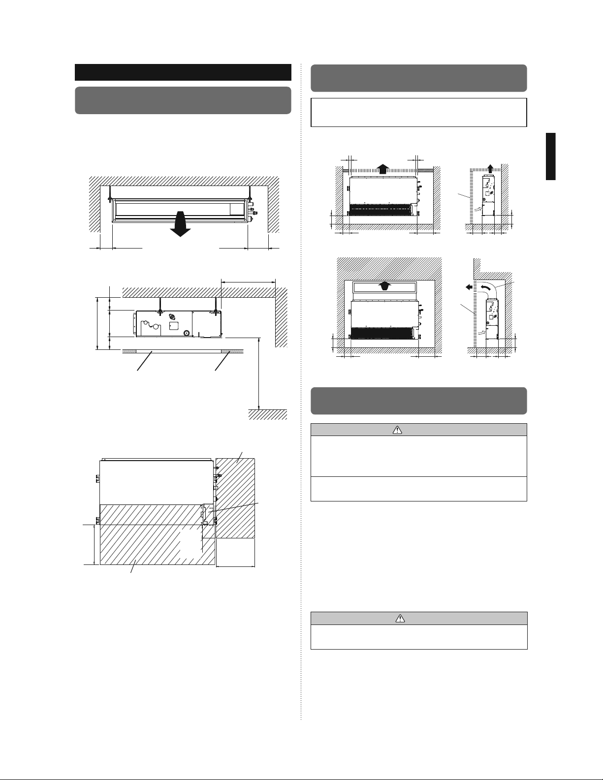
6.1A. Installation dimensions
(Ceiling concealed type)
Provide a service access for inspection purposes.
Do not place any wiring or illumination in the service space,
as they will impede service.
Installation Dimensions
Strong and durable ceiling
unit: mm (in.)
6.1B.
Installation dimensions (Wall mounted
type/Floor standing concealed type)
The wall mounted type/floor standing concealed type
requires a temperature correction setting. Perform this in
“10.3. Function setting”.
unit: mm (in.)
Left side
10 (13/32)
or less
10 (13/32)
or less
Right side
(PIPE side)
Left
side
100 (3-15/16)
or more
more
240 (9-7/16) or
20 (25/32) or more
20 (25/32) or more
Service access Ceiling
Indoor unit
300 (11-13/16)
or more
300 (11-13/16) or more
more
(When no ceiling)
2500 (8 ft 3 in.) or
Floor
Adjust the wind direction in the room depending on the
shape of blow out opening.
Service access
Unit
Control
box
300 (11-13/16)
100 (3-15/16)
or more
300 (11-13/16)
or more
Service space
or more
Right
side
150 (5-29/32)
or more
100 (3-15/16)
or more
Left side
150 (5-29/32)
or more
100 (3-15/16)
or more
Strong and
durable floor
Strong and
durable floor
6.2A. Installation the unit
(Ceiling concealed type)
Install the air conditioner in a location which can withstand a
load do at least 5 times the weight of the main unit and which
will not amplify sound or vibration. If the installation location is
not strong enough, the indoor unit may fall and cause injuries.
If the job is done with the panel frame only, there is a risk that
the unit will come loose. Please take care.
6.2A.1. UNIT INSTALLATION EXAMPLE (CEILING
CONCEALED TYPE)
Connect the locally purchased duct.
(1) Inlet side
• Connect the duct to the locally purchased inlet flange.
• Connect the flange to the body with the locally purchased
tapping screws.
• Wind the inlet flange connecting to the duct with the
aluminum tape etc. to avoid the air discharge.
300 (11-13/16)
or more
300 (11-13/16)
or more
WARNING
Grill
Inlet air
Strong and
durable floor
20 (25/32)
or more
Right side
(PIPE side)
Grill
Inlet air
Strong and
durable floor
20 (25/32)
or more
20 (25/32)
or more
20 (25/32)
or more
150 (5-29/32)
or more
Duct
150 (5-29/32)
or more
CAUTION
When the duct is connected to inlet side, remove contained
filter and surely attach locally purchased filter at inlet opening.
(2) Outlet side
• Connect the duct with adjusting inside of outlet flange.
• Wind the outlet flange connecting to the duct with the
aluminum tape etc. to avoid the air discharge.
• Insulate the duct to avoid the dew condensation.
En-7
Page 8
CAUTION
Check that duct work does not exceed the range of external
static pressure of equipment.
Make sure to insulate ducts to avoid condensation.
Make sure to insulate between ducts and walls if metal ducts
are used.
Please explain handling and washing methods of locally
purchased materials to the customer.
To prevent people from touching the parts inside the unit, be
sure to install grilles on the inlet and outlet ports. The grilles
must be designed in such a way that cannot be removed
without tools.
When connecting the duct to the outlet port of the indoor unit,
be sure to insulate the outlet port and the installation screws
to prevent water from leaking around the port.
AR9/12/18 Model
• Set the static pressure outside the unit to 0.36 in. WG or
less (the allowable range is between 0 and 0.36 in. WG).
AR24 Model
• Set the static pressure outside the unit to 0.2 in. WG or
less (the allowable range is between 0 and 0.2 in. WG).
Replace the cover as follows.
• Remove the screws, and then remove cover and fan
guard.
• Install the cover with the screws as shown in the illustration
below.
Model
Screw
M5
AR9/12 9
AR18 11
AR24 13
screw (M5)
Cover
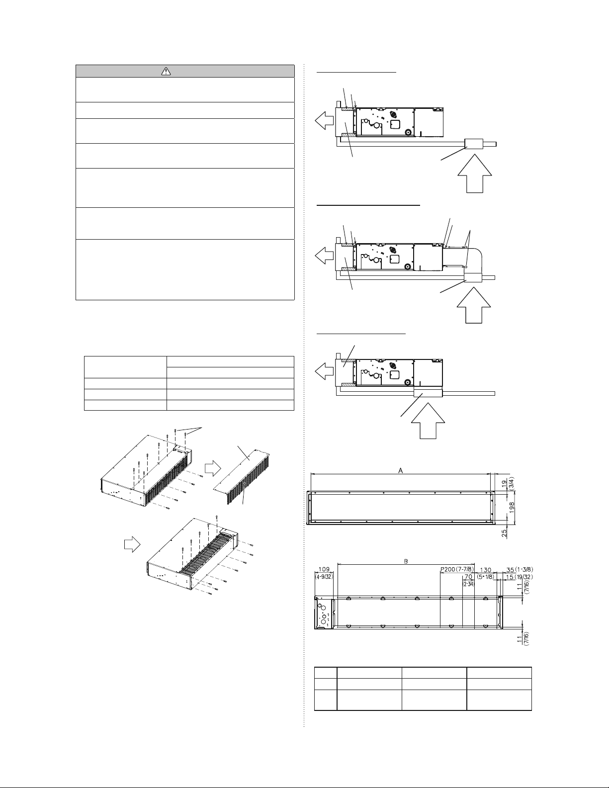
Side Inlet - Side Outlet
Insulation material (Field supply)
Aluminum tape
Flange (Field supply)
Air
Duct
(Field supply)
Intake grille
(Field supply)
Side Inlet - Side Outlet (Duct)
Insulation material (Field supply)
Aluminum tape
Flange (Field supply)
Air
Duct
(Field supply)
Intake grille
(Field supply)
Bottom Inlet - Side Outlet
Duct (Field supply)
Air
Intake grille (Field supply)
Outlet side
Flange (Field supply)
Aluminum tape
Air
Air
Tapping screw for
flange connection
(M5 x 10 mm /
Field supply)
Air
unit: mm (in.)
25 (31/32
)
En-8
Fan guard
Inlet side
unit: mm (in.)
AR9/12 AR18 AR24
A 650 (25-19/32) 850 (33-15/32) 1050 (41-11/32)
P200 (7-7/8) × 2
B
= 400 (15-3/4)
P200 (7-7/8) × 3
= 600 (23-5/8)
P200 (7-7/8) × 4
= 800 (31-1/2)
)
7-25/32
(
)
31/32
(
Page 9

6.2A.2. INSTALL THE FILTERS
• Install the filters to the unit.
6.2A.4. FIX THE UNIT
(1) Hang the unit
Hanger
Hanger bolt
Nut A
(Field supply)
Washer
(Accessories)
Nut B
(Field supply)
Filter (Accessories)
AR9/12/18: 2 filters
AR24: 3 filters
Unit
Filter
6.2A.3. DRILLING HOLES FOR BOLTS AND INSTALLING THE BOLTS
• Using the installation template, drill holes for bolts (4 holes).
Installation template
Drilling position
for bolts
Hanger bolt
Nut A
(Field supply)
Washer
(Accessories)
Nut B
(Field supply)
*:
It might become difficult to open and shut the Cover /control
Hanger
Unit
20 mm
(25/32 in.)
length
Cover
box cover when the length exceeds 20 mm (25/32 in.).
(2) Leveling
Base horizontal direction leveling on top of the unit.
Ceiling
Level
Air
377 mm
(14-27/32)
A
unit: mm (in.)
AR9/12 AR18 AR24
A 734 (28-29/32) 934 (36-25/32) 1134 (44-21/32)
OK
NO GOOD
10mm (13/32 in.) or less
En-9
Page 10

Level
Air
CAUTION
Leave a space of 100 mm (3-15/16 in.) or more between the
inlet port and the ceiling.
Fasten the unit securely with Special nuts A and B.
6.2B.1. UNIT INSTALLATION EXAMPLE
(Wall mounted type/Floor standing concealed
type)
Connect the locally purchased duct.
(1) Inlet side
• Connect the duct to the locally purchased inlet flange.
• Connect the flange to the body with the locally purchased
tapping screws.
• Wind the inlet flange connecting to the duct with aluminum
tape etc. to avoid the air discharge.
CAUTION
When duct is connected to inlet side, remove filter provided
with unit and attach locally purchased filter at return air grille
or in return duct.
6.2B. Install the unit (Wall mounted type/
Floor standing concealed type)
WARNING
Install the air conditioner in a location which can withstand a
load do at least 5 times the weight of the main unit and which
will not amplify sound or vibration. If the installation location is
not strong enough, the indoor unit may fall and cause injuries.
If the job is done with the panel frame only, there is a risk that
the unit will come loose. Please take care.
(2) Outlet side
• Connect the duct to outlet flange.
• Wind the outlet flange connecting to the duct with
aluminum tape etc. to avoid the air discharge.
• Insulate the duct to avoid condensation.
CAUTION
Check that duct work does not exceed the range of external
static pressure of equipment.
Make sure to insulate ducts to avoid condensation.
Make sure to insulate between ducts and walls if metal ducts
are used.
Please explain handling and washing methods of locally
purchased materials to the customer.
To prevent people from touching the parts inside the unit, be
sure to install grilles on the inlet and outlet ports. The grilles
must be designed in such a way that cannot be removed
without tools.
When connecting the duct to the outlet port of the indoor unit,
be sure to insulate the outlet port and the installation screws
to prevent water from leaking around the port.
AR9/12/18 Model
• Set the static pressure outside the unit to 0.36 in. WG or less
(the allowable range is between 0 and 0.36 in. WG).
AR24 Model
• Set the static pressure outside the unit to 0.2 in. WG or less
(the allowable range is between 0 and 0.2 in. WG).
• Remove the screws, and then remove cover and fan
guard.
• Install the cover with the screws as shown in the illustration
below.
Model
Screw
M5
AR9/12 9
AR18 11
AR24 13
En-10
Page 11

6.2B.2. INSTALL THE FILTER
• Install the filters (Accessories) to the unit.
AR9/12/18: 2 filters
AR24: 3 filters
6.2B.3. INSTALLING THE UNIT
• To prevent overturning, attach the unit to the floor or the
wall.
• To avoid vibration of the unit, install vibration isolation pad
between the unit and the floor or the wall.
Leveling
Level unit before attaching to floor or wall.
Level
Filter
Unit
Replace drain cap
• Set “10.4. Jumper wire setting of Drainage function setting
(JM1)”.
• Drain pump cannot be used if it is installed in wall mounted
type/floor standing concealed type.
Filter
CAUTION
OK
10 mm or less
(13/32 in.)
Level
NO GOOD
10 mm or less
(13/32 in.)
NO GOODOK
CAUTION
Fasten the unit securely with Special nuts A and B.
En-11
Page 12

7. PIPE INSTALLATION
CAUTION
Be careful that foreign matter (oil, water, etc.) does not enter
the piping with refrigerant R410A models. Also, when storing
the piping, securely seal the openings by pinching, taping,
etc.
While brazing the pipes, be sure to purge with dry nitrogen
gas.
7.1. Selecting the pipe material
CAUTION
Do not use existing pipes.
Use pipes that have clean external and internal sides without
any contamination which may cause trouble during use, such
as sulfur, oxide, dust, cutting waste, oil, or water.
It is necessary to use seamless copper pipes.
Material : Phosphor deoxidized seamless copper pipes
It is desirable that the amount of residual oil is less than
40 mg/10 m (33 ft).
Do not use copper pipes that have a collapsed, deformed,
or discolored portion (especially on the interior surface).
Otherwise, the expansion valve or capillary tube may become
blocked with contaminants.
Improper pipe selection will degrade performance. As an air
conditioner using R410A incurs pressure higher than when
using conventional refrigerant, it is necessary to choose
adequate materials.
7.2. Pipe requirement
CAUTION
Refer to the Installation Manual of the outdoor unit for
description of the length of connecting pipe or for difference
of its elevation.
• Use pipe with water-resistant heat insulation.
CAUTION
Install heat insulation around both the gas and liquid pipes.
Failure to do so may cause water leaks.
Use heat insulation with heat resistance above 248°F.
(Reverse cycle model only)
In addition, if the humidity level at the installation location
of the refrigerant piping is expected to exceed 70 %,
install heat insulation around the refrigerant piping. If the
expected humidity level is 70-80 %, use heat insulation
that is 15mm(19/32 in.) or thicker and if the expected
humidity exceeds 80 %, use heat insulation that is
20mm(25/32 in.) or thicker. If heat insulation is used
that is not as thick as specified, condensation may form
on the surface of the insulation. In addition, use heat
insulation with heat conductivity of 0.045 W/(m·K) or less
(at 68°F).
7.3. Flare connection (Pipe connection)
WARNING
Tighten the flare nuts with a torque wrench using the
specified tightening method. Otherwise, the flare nuts could
break after a prolonged period, causing refrigerant to leak
and generate a hazardous gas if the refrigerant comes into
contact with a flame.
•
Thicknesses of copper pipes used with R410A are as
shown in the table.
•
Never use copper pipes thinner than those indicated in the
table even if they are available on the market.
Thicknesses of Annealed Copper Pipes (R410A)
Pipe outside diameter [mm (in.)] Thickness [mm (in.)]
6.35 (1/4) 0.80 (0.032)
9.52 (3/8) 0.80 (0.032)
12.70 (1/2) 0.80 (0.032)
15.88 (5/8) 1.00 (0.039)
19.05 (3/4) 1.20 (0.047)
7.3.1. Flaring
• Use special pipe cutter and flare tool exclusive for R410A.
(1)
Cut the connection pipe to the necessary length with a
pipe cutter.
(2)
Hold the pipe downward so that cuttings will not enter the
pipe and remove any burrs.
(3)
Insert the flare nut (always use the flare nut attached to
the indoor and outdoor units respectively) onto the pipe
and perform the flare processing with a flare tool. Use
the special R410A flare tool, or the conventional flare
tool. Leakage of refrigerant may result if other flare nuts
are used.
(4)
Protect the pipes by pinching them or with tape to
prevent dust, dirt, or water from entering the pipes.
En-12
Page 13

Check if [L] is flared uniformly
Wid
oss
flats
and is not cracked or scratched.
Die
A
Pipe
Pipe outside
diameter
[mm (in.)]
6.35 (1/4)
9.52 (3/8) 13.2 (17/32)
12.70 (1/2) 16.6 (21/32)
15.88 (5/8) 19.7 (25/32)
Dimension A
[mm (in.)]
Flare tool for R410A,
clutch type
0 to 0.5
(0 to 0.020)
Dimension B
[mm (in.)]
9.1 (11/32)
-00.4
19.05 (3/4) 24.0 (15/16)
When using conventional flare tools to flare R410A pipes,
the dimension A should be approximately 0.5 mm (0.020 in.)
more than indicated in the table (for flaring with R410A flare
tools) to achieve the specified flaring. Use a thickness gauge
to measure the dimension A.
Width across
th acr
flats
Pipe outside
diameter [mm (in.)]
Width across flats
of Flare nut [mm (in.)]
6.35 (1/4) 17 (21/32)
9.52 (3/8) 22 (7/8)
12.70 (1/2) 26 (1-1/32)
15.88 (5/8) 29 (1-5/32)
19.05 (3/4) 36 (1-13/32)
7.3.2. Bending pipes
•
If pipes are shaped by hand, be careful not to collapse
them.
•
Do not bend the pipes in an angle more than 90°.
•
When pipes are repeatedly bend or stretched, the material
will harden, making it difficult to bend or stretch them any
more.
•
Do not bend or stretch the pipes more than 3 times.
CAUTION
To prevent breaking of the pipe, avoid sharp bends.
If the pipe is bent repeatedly at the same place, it will break.
7.3.3. Pipe connection
CAUTION
Be sure to install the pipe against the port on the indoor unit
correctly. If the centering is improper, the flare nut cannot
tighten smoothly. If the flare nut is forced to turn, the threads
will be damaged.
Do not remove the flare nut from the indoor unit pipe until
immediately before connecting the connection pipe.
Hold the torque wrench at its grip, keeping it at a right angle
with the pipe, in order to tighten the flare nut correctly.
Tighten the flare nuts with a torque wrench using the specified
tightening method. Otherwise, the flare nuts could break after
a prolonged period, causing refrigerant to leak and generate
a hazardous gas if the refrigerant comes into contact with a
flame.
CAUTION
Connect the piping so that the control box cover can easily be
removed for servicing when necessary.
In order to prevent water from leaking into the control box,
make sure that the piping is well insulated.
When the flare nut is tightened properly by your hand, hold
the body side coupling with wrench, then tighten with a torque
wrench. (See the table below for the flare nut tightening
torques.)
Tighten with 2 wrenches.
Holding wrench
Torque wrench
Indoor unit pipe
(Body side)
Flare nut
Connection pipe
Flare nut [mm (in.)] Tightening torque [N·m (lbf·ft)]
6.35 (1/4) dia. 16 to 18 (11.8 to 13.3)
9.52 (3/8) dia. 32 to 42 (23.6 to 31.0)
12.70 (1/2) dia. 49 to 61 (36.1 to 45.0)
15.88 (5/8) dia. 63 to 75 (46.5 to 55.3)
19.05 (3/4) dia. 90 to 110 (66.4 to 81.1)
7.4. Installing heat insulation
Install the heat insulation material after performing a
refrigerant leak check (see the Installation Manual for the
outdoor unit for details).
7.4.1. COUPLER HEAT INSULATION
• Insulate with the coupler heat insulation (Accessories)
around the gas pipe and liquid pipe at indoor unit.
• After installing the coupler heat insulation, wrap both ends
with vinyl tape so that there is no gap.
• After affixing the coupler heat insulation, secure it with 2
binders (large), one on each end of the insulation.
• Make sure that the binders overlap the heat insulation
pipe.
Coupler heat
insulation
(Accessories)
Binder (Large)
(Accessories)
After checking for gas leaks (refer to the Installation Manual of
the outdoor unit), perform this section.
Install heat insulation around both the large (gas) and small
(liquid) pipes. Failure to do so may cause water leaks.
Cover this portion with
heat insulation.
Heat insulation
CAUTION
En-13
Page 14

8. INSTALLING DRAIN PIPES
8.1A. Installing drain pipes
(Ceiling concealed type)
Use general hard polyvinyl chloride pipe and connect it with
adhesive (polyvinyl chloride) so that there is no leakage.
Always heat insulate the indoor side of the drain hose.
Use a drain pipe that matches the size of the drain hose
(Table A).
• Do not perform a rise, trap and air bleeding.
• Provide a downward gradient (1/100 or more).
• Provide supports when long pipes are installed.
• Use an insulation material as needed, to prevent the pipes
from freezing.
• Install the pipes in a way that allows for the removal of the
control box.
Table A
Pipe Size
Drain pipe 3/4 in. (O.D. 1-1/16 in.)
• CEILING CONCEALED TYPE (Use Drain Pump)
Outlet air
flow
OK
Arrange the drain hose
lower than this port.
OK
8.1B. Installing drain pipes (Wall mounted
OK
Drain hose
NO GOODDrain cap NO GOOD
Supporter
1.5-2 m
(5'- 6' 6")
Trap
Air bleeding
NO GOOD
type/Floor standing concealed type)
Drain
cap
NO GOOD
NO GOOD
Rise
RiseTrap
• Install the drain pipe with downward gradient (1/50 to
1/100) and so there are no rises or traps in the pipe.
• Use general hard polyvinyl chloride pipe [19 mm (3/4 in.)
O.D. 27 mm (1-1/16 in.)] and connect it with adhesive
(polyvinyl chloride) so that there is no leakage.
• When the pipe is long. Install supports.
• Do not perform air bleeding.
• Always heat insulate the indoor side of the drain pipe.
Gap of 1.5-2 m (5' - 6' 6")
Locally arranged pipe
Max.
300 mm (11-13/16 in.)
O.D.1-1/16 in.
(27 mm)
700 mm (27-9/16 in.) or less
Horizontal or
upward gradient
Trap
Supporter
RiseAir bleeding
BAD
Observe the following procedures to construct centralized
drain pipe fittings.
O.D. 1-5/16 in. (33 mm) or more
Downward gradient 1/100 or more
700 mm
(27-9/16 in.)
or less
WARNING
Do not insert the drain piping into the sewer where sulfurous
gas occurs. (Heat exchange erosion may occur)
Insulate the parts properly so that water will not drip from the
connection parts.
Check for proper drainage after the construction by using the
visible portion of transparent drain port and the drain piping
final outlet on the body.
CAUTION
• Drain pump cannot be used if it is installed in wall mounted
type/floor standing concealed type.
• Set “10.4.Jumper wire setting of Drainage function setting
(JM1)”.
• Be sure to connect the pipes for drainage without leakage.
• To avoid condensation and dripping, always insulate the
indoor drain pipe.
En-14
CAUTION
Do not apply adhesive agent on the drain port of the body.
(Use the attached drain hose and connect the drain piping)
Page 15

8.2. Install the drain pipe
(1) Be sure to use supplied Drain hose 1 and Hose band 2
Hose band
2
Drain hose
1
Drain
hole
• When drain pump is used. (Ceiling concealed type only)
Hose band
4 mm (5/32 in.) or less
Hard PVC side
CAUTION
Do not connect to the Drain hole with adhesive. Using
adhesive may cause damage and water leaks.
(3) After installing the Drain hose 1, check if the drainage is
smooth.
• When drain pump is not used. (Natural drainage)
Downward
gradient
2.5-5.0 mm
(0.10-0.19 in.)
CAUTION
To prevent excessive force on Drain hose 1, avoid bends or
twists. (To bend or twist may cause water leaks.)
20 mm (25/32 in.)
• When drain pump is not used. (Natural drainage)
Applying
area of
adhesive
4 mm (5/32 in.) or less
Joint pipe
(Field supply)
Drain pipe [3/4 in. (O.D.1-1/16 in.)]
(Field supply)
CAUTION
When drain pump is not used, do not connect the accessory
drain hose and soft PVC hose directly.
(2) Be sure to insert Drain hose 1 to the very end of the Drain
pan of the unit with no space.
Applying
area of
adhesive
4 mm (5/32 in.) or less
Joint pipe
(Field supply)
Drain pipe [3/4 in. (O.D.
1-1/16 in.)] (Field supply)
(4) After checking for drainage, attach the Drain hose
insulation B 3 to insulate, following the instructions as in
the figures.
To avoid space with Drain hose 1 and Hose band 2,
press firmly the Drain hose insulation B 3.
• When drain pump is used. (Ceiling concealed type only)
Ensure there is
no space.
3
Drain hose
insulation B
• When drain pump is not used. (Natural drainage)
Ensure there is
no space.
3
Drain hose
insulation B
1
Drain hose
Fasten the Hose band 2 at the position where
vertical against ground.
The Hose band 2 must be positioned at the
right side of the Drain hose
2
Hose band
1
as in the figure.
En-15
Page 16

• STEP1~STEP3
Butt the insulation
against the unit.
STEP 1
Unit
Note: Check for drainage
Pour about 1 liter of water from the position shown in the
diagram or from the airflow outlet to the condensate tray. Check
for any abnormalities such as strange noises and whether the
drain pump functions normally.
Slit
Press firmly
STEP 2
Slit
Press firmly
Roll the
insulation
over the joint.
STEP 3
Press firmly
Slit
Press firmly
Press firmly
• FINISH
Check that there is no gap between the unit and the drain
hose insulation.
• When drain pump is used. (Ceiling concealed type only)
Do not cover the
panel window.
CAUTION
Make sure the drain water is properly drained.
9. ELECTRICAL WIRING
WARNING
Before starting work, check that power is not being supplied
to the indoor unit and outdoor unit.
Match the terminal board numbers and connection cord colors
with those of the outdoor unit or branch box. Erroneous wiring
may cause burning of the electric parts.
Connect the connection cords firmly to the terminal board.
Imperfect installation may cause a fire.
Always fasten the outside covering of the connection cord
with the cable clip. (If the insulator is chafed, electric leakage
may occur.)
Always connect the ground wire.
(1) Use ring terminals with insulating sleeves as shown in the
figure below to connect to the terminal block.
(2) Securely clamp the ring terminals to the wires using an
appropriate tool so that the wires do not come loose.
(3)
Use the specified wires, connect them securely, and fasten
them so that there is no stress placed on the terminals.
(4)
Use an appropriate screwdriver to tighten the terminal screws.
Do not use a screwdriver that is too small, otherwise, the
screw heads may be damaged and prevent the screws
from being properly tightened.
(5) Do not tighten the terminal screws too much, otherwise,
the screws may break.
(6) See the table 1 for the terminal screw tightening torques.
• When drain pump is not used. (Natural drainage)
Do not cover the
control box cover.
En-16
Strip 10 mm (13/32")
Screw with
special washer
Wire
Ring terminal
Terminal
board
Terminal block
Ring terminal
Wire
Sleeve
Screw with
special washer
Ring
terminal
Page 17

WARNING
Use ring terminals and tighten the terminal screws to the
specified torques, otherwise, abnormal overheating may be
produced and possibly cause heavy damage inside the unit.
Table 1
Tightening torque
M4 screw 1.2 to 1.8 N·m (11 to 16 lbf·in)
Binder (Medium)
(Accessories)
Remote control cable
9.1. INDOOR UNIT SIDE
(1) Remove the control box cover from the control box.
Screw
Control box cover
Remove the 4 screws
and remove the control
box cover from the
control box.
(2) Cable connection
• Connect the connection cable to the terminal board.
• Connect the remote controller cable to the terminal board.
• Fix the remote controller cable to the control box cover
with a nylon clamp.
Remote control cable
1: Red
2: White
3: Black
Binder (Medium)
(Accessories)
GND
Conduit
(Field supply)
Power supply cable
Conduit
(Field supply)
Power supply cable
(3) Wiring system diagram
INDOOR UNIT SIDE
INDOOR UNIT
TERMINAL
Remote controller line
DISCONNECT
SWITCH
(Field supply)
14AWG
(Inter-unit)
Power lines
208/230 V
208/230 V
208/230 V
Grounding
line
OUTDOOR UNIT
or BRANCH BOX
Disconnect Switch - Field supplied if required by local code.
Select the correct capacity of disconnect switch according to
the load.
CAUTION
Tighten the indoor unit connection cable and power
supply indoor and outdoor unit, branch box terminal
board connections firmly with the terminal board screws.
Faulty connection may cause a fire.
If the indoor unit connection cable and power supply are
wired incorrectly, the air conditioner may be damaged.
Connect the indoor unit connection cable by matching
the numbers of the outdoor, branch box and indoor units
terminal board numbers as shown in terminal label.
Ground both the indoor and outdoor, branch box units by
attaching a ground cable.
Unit shall be grounded in compliance with the applicable
local and national rules.
φ22.2 mm
(7/8 in.)
Conduit
(Field supply)
WARNING
Disconnect switch for over current protection given in
the system diagram is to be installed between the indoor
unit and the outdoor unit, branch box.
CAUTION
Be sure to refer to the above diagram for do correct field
wiring. Wrong wiring causes malfunction of the unit.
Check local electrical rules and also any specific wiring
instructions or limitation.
En-17
Page 18

10. REMOTE CONTROLLER SETTING
.
CAUTION
When detecting the room temperature
using the remote controller, please
set up the remote controller according to the following conditions. If the
remote controller is not located properly, the correct room temperature
will not be detected, and thus abnormal conditions like “not cooled” or
“not heated” will occur even if the airconditioner is running normally.
• Locate where an average temperature for the room
being air conditioned will be sensed.
• Do not locate directly exposed to the outlet air from
the air-conditioner.
• Locate out of direct sunlight.
• Locate away from the influence of other heat sources.
Do not touch the remote controller PC board and PC
board parts directly with your hands.
Do not wire the remote controller cable together with or
parallel to the connection cables, and power supply cable of the INDOOR UNIT and OUTDOOR UNIT, BRANCH
BOX. It may cause erroneous operation.
When installing the bus wire near a source of electromagnetic waves, use shielded wire.
Do not set the DIP switches, either on the air conditioner or the remote controller, in any way other than
indicated in this manual that is supplied with the air
conditioner. Doing so may result in improper operation.
Temperature
sensor
Hole
Binder
(Small)
[Example]
1. Red
Box
Rear case
120 (4-23/32)
2. White
3. Black
CAUTION
When connecting the
remote controller wires, do
not overtighten the screws.
Remote
controller cable
Connector
Screws
17
(21/32)
120 (4-23/32)
10.1. Installing the remote controller
Open the operation panel on the front of the remote controller, remove the 2 screws indicated in the following figure, and
then remove the front case of the remote controller.
When installing the remote controller, remove the connector
from the front case. The wires may break if the connector is
not removed and the front case hangs down.
When installing the front case, connect the connector to the
front case.
Front case
SET BACK
Screws
(back side)
Connector
Rear case
When remote controller cable is concealed
(1) Conceal the remote controller cable.
(2) Pass the remote controller cable through the hole in the
rear case and connect the remote controller cable to the
remote controller terminal board specified in figure.
(3) Clamp the remote controller cable sheath with the binder
as shown in figure.
(4) Cut off the excess binder.
(5) Install the rear case to the wall, box, etc., with 2 screws
figure.
En-18
30
(1-3/16)
Hole
45.3
(1-25/32)
12.5
4.5
(1-5/16)
(29/32)
4.5 (3/16)
(1/2)
(3/16)
33.5
23
8
(11/32)
4.5 (3/16)
6
(1/4)
Hole × 3
Hole × 2
15.3
(19/32)
63.5 (2-1/2)
83.5 (3-9/32)
Unit: mm (in.)
CAUTION
Install the remote controller wires so as not to be
direct touched with your hand.
Do not touch the remote controller PC board and PC
board parts directly with your hands.
Page 19

10.2. Setting the dip switches
Set the remote controller DIP switches.
[Example]
Front case (back side)
OFF
1
2
3
4
5
6
DIP switch 1
ON
10.3. Function setting
This procedure changes the function settings used to control
the indoor unit according to the installation conditions. Incorrect
settings can cause the indoor unit to malfunction. This procedure should be performed by authorized installation or service
ON
personnel only.
Perform the “FUNCTION SETTING” according to the installation
conditions using the remote controller. (Refer to the indoor unit
installation manual for details on the function numbers and setting values.)
(1) Press the SET TEMP. buttons (
) ( ) and FAN button
simultaneously for more than 5 seconds to enter the function
setting mode.
DIPswitch 1
NO.
1
2
3
4
5
SW state
OFF ON
)
)
)
)
)
6)Invalidity Validity
Detail
Cannot be used.
(Do not change)
Dual remote controller setting
Refer to 2. DUAL REMOTE
*
CONTROLLERS in 11
SPECIAL INSTALLATION
METHODS.
Cannot be used.
(Do not change)
Cannot be used.
(Do not change)
Cannot be used.
(Do not change)
Memory backup setting
Set to ON to use batteries
*
for the memory backup. If
batteries are not used, all
of the settings stored in
memory will be deleted if
there is a power failure.
() Factory setting)
SUMOTUWETH FR
SA
(2) Press the SET BACK button to select the indoor unit num-
ber.
SET BACK
SUMOTUWETH FR
SA
Unit number of INDOOR UNIT
(3) Press the SET TIME ( ) buttons to select the function
number.
SUMOTUWETH FR
Function number
SA
En-19
Page 20

(4) Press the SET TEMP. buttons ( ) ( ) to select the set-
ting value.
The display flashes as shown to the right during setting
value selection.
SUMOTUWETH FR
SA
• Function Details
(1) Filter Sign
The indoor unit has a sign to inform the user that it is time to
clean the filter. Select the time setting for the filter sign display
interval in the table below according to the amount of dust
or debris in the room. If you do not wish the filter sign to be
displayed, select the setting value for “No indication”.
(♦... Factory setting)
Setting description
Standard (400 hours)
Function
number
Setting
value
00
Setting value
(5) Press the TIMER SET button to confirm the setting.
Press the TIMER SET button for a few seconds until the
setting value stops flashing.
If the setting value display changes or if “- -” is displayed
when the flashing stops, the setting value has not been
set correctly.
(An invalid setting value may have been selected for the
indoor unit.)
(6) Repeat steps 2 to 5 to perform additional settings.
Press the SET TEMP. buttons (
simultaneously again for more than 5 seconds to cancel
the function setting mode. In addition, the function setting
mode will be automatically canceled after 1 minute if no
operation is performed.
(7) After completing the FUNCTION SETTING, be sure to
turn off the power and turn it on again.
) ( ) and FAN button
Long interval (1000 hours) 01
Short interval (200 hours) 02
♦
No indication 03
11
(2) Static pressure
Select appropriate static pressure according to the installation
conditions.
(♦... Factory setting)
Setting description
0 in. WG (0 Pa)
0.04 in. WG (10 Pa) 01
0.08 in. WG (20 Pa) 02
0.12 in. WG (30 Pa) 03
0.16 in. WG (40 Pa) 04
0.20 in. WG (50 Pa) 05
0.24 in. WG (60 Pa) 06
0.28 in. WG (70 Pa) 07
0.32 in. WG (80 Pa) 08
0.36 in. WG (90 Pa) 09
♦ 0.1 in. WG (25 Pa) [Standard] 31
Range of static pressure is different from one model to other.
Model name Range of static pressure
ARU9RLF
0 to 0.36 in. WG (0 to 90 Pa)ARU12RLF
ARU18RLF
ARU24RLF 0 to 0.2 in. WG (0 to 50 Pa)
Function
number
26
Setting
value
00
En-20
(3) Cooling room temperature correction
Depending on the installed environment, the room temperature sensor may require a correction.
The settings may be selected as shown in the table below.
(♦... Factory setting)
Setting description
♦
When using floor console installation, change the setting
value to "01".
Standard
Slightly lower control 01
Lower control 02
Warmer control 03
Function
number
30
Setting
value
00
Page 21

(4) Heating room temperature correction
Depending on the installed environment, the room
temperature sensor may require a correction.
The settings may be changed as shown in the table below.
(♦... Factory setting)
Setting description
♦
When using floor console installation, change the setting
value to "01".
Standard
Lower control 01
Slightly warmer control 02
Warmer control 03
Function
number
31
Setting
value
00
(5) Auto restart
Enable or disable automatic system restart after a power
outage.
Setting description
♦
* Auto restart is an emergency function such as for power fail-
ure etc. Do not start and stop the indoor unit by this function
in normal operation. Be sure to operate by the control unit,
or external input device.
(6)
Indoor room temperature sensor switching function
(Only for Wired remote controller)
The following settings are needed when using the Wired
remote controller temperature sensor.
Setting description
♦
* If setting value is “00” :
Room temperature is controlled by the indoor unit
temperature sensor.
* If setting value is “01” :
Room temperature is controlled by either indoor unit
temperature sensor or remote controller unit sensor.
Yes
No 01
No
Yes 01
(♦... Factory setting)
Function
number
40
(♦... Factory setting)
Function
number
42
Setting
Setting
value
00
value
00
(7) Wireless remote controller signal code
Change the indoor unit Signal Code, depending on the
wireless remote controllers.
(♦... Factory setting)
Setting description
♦
A
Function
number
Setting
value
00
(8) External input control
"Operation/Stop" mode or "Forced stop" mode can be
selected.
Setting description
♦ Operation/Stop mode
(Setting forbidden) 01
Forced stop mode 02
(♦... Factory setting)
Function
number
46
Setting
value
00
Setting record
Record any changes to the settings in the following table.
•
Setting Setting Value
(1) Filter sign
(2) Static pressure
(3) Cooler room temperature correction
(4) Heater room temperature correction
(5) Auto restart
(6) Indoor room temperature sensor
switching function
(7) Wireless remote controller signal code
(8) External input control
After completing the FUNCTION SETTING, be sure to turn off
the power and turn it on again.
SETTING THE ROOM TEMPERATURE
DETECTION LOCATION
The detection location of the room temperature can be selected from the following 2 examples. Choose the detection
location that is best for the installation location.
A. Indoor unit setting (factory setting)
The room temperature is detected by the indoor unit temperature sensor.
(1) When the THERMO SENSOR button is pressed, the lock
display flashes because the function is locked at the factory.
A
Indoor unit
F
F
B01
44
C02
D03
En-21
Page 22

B. Indoor unit/remote controller setting
(room temperature sensor selection)
The temperature sensor of the indoor unit or the remote controller can be used to detect the room temperature.
(1) Enable the room temperature sensor selection in FUNC-
TION SETTING, which will be previous page.
(2) Press the THERMO SENSOR button for 5 seconds or
more to select the temperature sensor of the indoor unit
or the remote controller.
B
Indoor unit
F
NOTES
If the function to change the temperature sensor is used as
shown in examples A (other than example B), be sure to lock
the detection location. If the function is locked, the lock display
pressed.
will flash when the THERMO SENSOR button is
10.4. Jumper wire setting
(1) Drainage function setting (JM1)
If contained drain pump is not used, set the drainage function
to “Invalid” in the drainage function switching.
If contained drain pump is not use:•
When used under “WALL MOUNTED TYPE/FLOOR
STANDING CONCEALED TYPE”.
When used in natural drainage under “CEILING CONCEALED TYPE”.
JM1 Drainage function
Connect Valid
♦
Disconnect Invalid
(2) Fan delay setting (JM3)
It is a function to delay the stop of cooling fan when the air
conditioner is stopped.
JM3 Fan delay
Connect Invalid
♦
F
(♦... Factory setting)
(♦... Factory setting)
10.5. Test run
CAUTION
Always turn on the power 12 hours prior to the start of the
operation in order to ensure compressor protection.
CHECK ITEMS
(1)
Is operation of each button on the remote control unit normal?
(2) Does each lamp light normally?
(3) Do not air flow direction louvers operate normally?
(4) Is the drain normal?
(5)
Is there any abnormal noise and vibration during operation?
• Do not operate the air conditioner in test run for a long time.
[OPERATION METHOD]
• For the operation method, refer to the operating manual.
(1) Stop the air conditioner operation.
(2)
Press the master control button and the fan control button
simultaneously for 2 seconds or more to start the test run.
Test run display
(3) Press the start/stop button to stop the test run.
If “C0” appears in the unit number display, there is a remote
controller error. Refer to the installation manual included with
the remote controller.
Unit number Error code Content
Incompatible indoor unit is
connected
Indoor unit ↔ remote controller communication error
[Using the wireless remote control for test run]
(Option)
• For the operation method, refer to the operating manual.
•
The outdoor unit may not operate depending on the
room temperature. In this case, press the test run button on the wireless remote control unit while the air conditioner is running. (Point the transmitter section of the
wireless remote control unit toward the air conditioner and
press the test run button with the tip of a ball-point pen, etc.)
Transmitter section
Disconnect Valid
• Switching position
• JM2 setting forbidden
En-22
Test run button
•
To end test operation, press the wireless remote control unit
START/STOP button.
(When the air conditioner is run by pressing the test run
button, the OPERATION indicator lamp and TIMER indicator lamp will simultaneously flash slowly.)
Page 23

11. SPECIAL INSTALLATION METHODS
CAUTION
When setting DIP switches, do not touch any other parts on
the circuit board directly with your bare hands.
Be sure to turn off the main power.
DUAL REMOTE CONTROLLERS
• 2 separate remote controllers can be used to operate the
indoor units.
•
The timer and self-diagnosis functions cannot be used on
the slave units.
(1) Wiring method (indoor unit to remote controller)
Indoor unit
12. OPTIONAL PARTS
]
WARNING
Refer to local codes for acceptable cable type.
12.1. External input and external output
Connection methods
• Wire modification
Remove insulation from wire attached to wire kit connector.
Remove insulation from field supplied cable.
Use crimp type insulated butt connector to join field cable and
wire kit wire.
Remote controller cable
Slave unitMaster unit
Remote controller
(2) Remote controller DIP switch 1 setting
Set the remote controller DIP switch 1 No. 2 according to
the following table.
Number of remote
controllers
Master unit Slave unit
DIP SW 1 No. 2 DIP SW 1 No. 2
1 (Normal) OFF –
2 (Dual) OFF ON
Insulated connection
Cable (Field supply)
Output terminal (CN103)
Input No Voltage terminal
(CN102)
Option parts
External input/output wire
Binder (Medium)
(Accessories)
En-23
Page 24

1
]
12.2. Remote sensor (Optional parts)
1
]
12.3. IR Receiver Unit (Optional parts)
Connection method
• Connection terminals
Remote sensor terminal (CN8)
• Wiring arrangement
Connection method
• Connection terminals
Reciever unit terminal (CN13)
• Wiring arrangement
Binder
Binder
• Remove the existing connector and replace it with the remote
sensor connector (ensure that the correct connector is used).
• The original connector should be insulated to ensure that it
does not come into contact with other electrical circuitry.
Setting for room temperature correction
When a remote sensor is connected, set the function setting
of indoor unit as indicated below.
• Set Function Number “30” (Cool air temperature trigger)
to “00” (Default)
• Set Function Number “31” (Hot air temperature trigger)
to “02” (Adjust(2))
• Use 7 pins for receiver unit cable.
•
At first, connect the receiver unit cable to the Receiver unit
terminal (CN13).
Binder
Avoid covering the air inlet
Power supply
cable
Avoid touching the ceiling with the wiring
Ceiling
with the wiring.
Do not bind the power supply cable and other cables together.
En-24
Page 25

13. ERROR CODES
If you use a wired type remote control, error codes will appear on the remote control display. If you use a wireless remote
control, the lamps on the IR receiver unit will output error codes by way of blinking patterns. See the lamp blinking patterns and
error codes in the table below. An error display is displayed only during operation.
Error display
OPERATION
lamp
(green)
TIMER
lamp
(orange)
ECONOMY
lamp
(green)
(1) (1)
(1) (2)
(1) (5)
(2) (1)
(2) (2)
(2) (3)
(2) (4)
(3) (2) Indoor unit
(3) (5) Indoor unit
(4) (1) Indoor unit
(4) (2) Indoor unit
(5) (1) Indoor unit
(5) (3) Indoor unit
(5) (15) Indoor unit
(6) (2) Outdoor unit
(6) (3) Outdoor unit
(6) (4) Outdoor unit
(6) (5) Outdoor unit
(6) (10) Outdoor unit
(7) (1) Outdoor unit
(7) (2) Outdoor unit
(7) (3) Outdoor unit
(7) (4) Outdoor unit
(7) (5) Outdoor unit
(7) (7) Outdoor unit
(8) (2) Outdoor unit
(8) (3) Outdoor unit
(8) (4) Outdoor unit
(8) (6) Outdoor unit
(9) (4) Outdoor unit
(9) (5) Outdoor unit
(9) (7) Outdoor unit
(9) (9) Outdoor unit
(10) (1)
(10) (3)
(10) (5)
(13) (2) Branch box
•Display mode : 0.5s ON / 0.5s OFF, ( ) : Number of flashing, : 0.1s ON / 0.1s OFF
Wired
remote
controller
Error code
Mode DESCRIPTION Remark
•
Communication
Communication
Communication
Function setting
Function setting
Function setting
Function setting
Serial communication error
Remote controller
communication error
Scan error
Initial setting error
Indoor unit capacity error
Connection disabled (series error)
Connection unit number error
Indoor unit main PCB error
Manual auto switch error
Room error
Indoor unit Heat Ex. sensor error
Indoor unit fan motor error
Water Drain error
Indoor unit error
Outdoor unit main PCB error
Inverter PCB error
Active filter error,
PFC circuit error
IPM error
Display panel error
Discharge thermistor error
Compressor thermistor error
Outdoor unit Heat Ex.
Sensor error
Outdoor thermistor error
Suction Gas thermistor error
Heat sink thermistor error
Sub-cool Heat Ex. gas
thermistor error
Liquid pipe thermistor error
Current sensor error
Pressure sensor error
Trip detection
compressor motor control error
Outdoor unit fan motor 1 error
4-way valve error
Refrigerant system
Refrigerant system
Refrigerant system
Discharge temperature 1 error
Compressor temperature error
Pressure error 2
Unit flow divider error
When the indoor unit cannot receive the signal from the branch unit
•
When the branch unit cannot receive the signal from the indoor unit
•Wired remote controller communication error
•
Check operation incompletion error (normally, operation disabled)
•Wiring mistake
•Indoor unit capacity error
•Combination error
•Connection unit number error (indoor unit)
•Connection unit number error (branch unit)
•Indoor unit PCB Model information error
•Manual auto switch error
•Inlet thermistor error
•Indoor unit Heat Ex. Middle thermistor error
•Main fan motor lock error
•Main fan motor revolution speed error
•Drain pump error
•Indoor unit error
•Outdoor unit PCB Model information error
•Outdoor unit PCB microcomputer communication error
•Inverter error
•Voltage error stoppage permanently
•Voltage error (can restore)
•Over current protected operation stoppage permanently
•PFC hardware error
•Trip terminal L error
•Microcomputers communication error
•Discharge thermistor 1 error
•Compressor thermistor 1 error
•Outdoor unit Heat Ex. liquid thermistor error
•Outdoor thermistor error
•Suction Gas thermistor error
•Heat sink thermistor error
•Sub-cool Heat Ex. gas inlet thermistor error
•Sub-cool Heat Ex. gas outlet thermistor error
•Liquid pipe thermistor 1 error
•Current sensor 1 error (stoppage permanently)
•Discharge pressure sensor error
•Suction pressure sensor error
•High pressure switch 1 error
•Trip detection
•Rotor position detection error (stoppage permanently)
•Duty error
•4-way valve error
•Discharge temperature 1 error
•Compressor 1 temperature error
•Low pressure error
•EEPROM access error
•Equipment type information error
•Serial communication error to outdoor unit
•Branch units serial communication error
•Serial communication error to indoor unit
•Liquid pipe thermistor error
•Gas pipe thermistor error
•Expansion valve full closure operation error
•Remote control communication error
•Branch unit error
En-25
Page 26

[Troubleshooting at the remote control LCD]
This is possible only on the wired remote control.
[Self-diagnosis]
If an error occurs, the following display will be shown.
(“Er” will appear in the set room temperature display.)
Error code
EX. Self-diagnosis
14. CUSTOMER GUIDANCE
Explain the following to the customer in accordance with the
operating manual:
(1) Starting and stopping method, operation switching,
temperature adjustment, timer, air flow switching, and other
remote control unit operations.
(2) Air filter removal and cleaning, and how to use the air louvers.
(3) Give the operating manual to the customer.
(4) If the wireless remote control signal code is changed from A
to B, C, or D, it will change back to A when the batteries in the
remote are replaced. Explain to the customer how to program
the wireless remote for the correct signal code.
En-26
 Loading...