

Fujitsu SK-MB91590-208M04 User Manual
Fujitsu Semiconductor Europe
FMEMCU-UG-910097-11
User Guide
SK-MB91590-208M04
FR FAMILY
MB91590 SERIES
STARTERKIT
USER GUIDE

Revision History
Date
Issue
2012/09/14
V1.0 ZRiaz, first version
2012/11/15
V1.1HLi, add FTDI driver and display initialization info, remove USB power
supply
This document contains 31 pages.
Revision History
UG-910097-11 - 2 - © Fujitsu Semiconductor Europe GmbH

Warranty and Disclaimer
Warranty and Disclaimer
The use of the deliverables (e.g. software, application examples, target boards, evaluation boards,
starter kits, schematics, engineering samples of IC’s etc.) is subject to the conditions of Fujitsu
Semiconductor Europe GmbH (“FSEU”) as set out in (i) the terms of the License Agreement and/or
the Sale and Purchase Agreement under which agreements the Product has been delivered, (ii) the
technical descriptions and (iii) all accompanying written materials.
Please note that the deliverables are intended for and must only be used for reference in an
evaluation laboratory environment.
The software deliverables are provided on an as-is basis without charge and are subject to
alterations. It is the user’s obligation to fully test the software in its environment and to ensure proper
functionality, qualification and compliance with component specifications.
Regarding hardware deliverables, FSEU warrants that they will be free from defects in material and
workmanship under use and service as specified in the accompanying written materials for a duration
of 1 year from the date of receipt by the customer.
Should a hardware deliverable turn out to be defect, FSEU’s entire liability and the customer’s
exclusive remedy shall be, at FSEU´s sole discretion, either return of the purchase price and the
license fee, or replacement of the hardware deliverable or parts thereof, if the deliverable is returned
to FSEU in original packing and without further defects resulting from the customer’s use or the
transport. However, this warranty is excluded if the defect has resulted from an accident not
attributable to FSEU, or abuse or misapplication attributable to the customer or any other third party
not relating to FSEU or to unauthorised decompiling and/or reverse engineering and/or
disassembling.
FSEU does not warrant that the deliverables do not infringe any third party intellectual property right
(IPR). In the event that the deliverables infringe a third party IPR it is the sole responsibility of the
customer to obtain necessary licenses to continue the usage of the deliverable.
In the event the software deliverables include the use of open source components, the provisions of
the governing open source license agreement shall apply with respect to such software deliverables.
To the maximum extent permitted by applicable law FSEU disclaims all other warranties, whether
express or implied, in particular, but not limited to, warranties of merchantability and fitness for a
particular purpose for which the deliverables are not designated.
To the maximum extent permitted by applicable law, FSEU’s liability is restricted to intention and
gross negligence. FSEU is not liable for consequential damages.
Should one of the above stipulations be or become invalid and/or unenforceable, the remaining
stipulations shall stay in full effect.
The contents of this document are subject to change without a prior notice, thus contact FSEU about
the latest one.
This board and its deliverables must only be used for
test applications in an evaluation laboratory
environment.
© Fujitsu Semiconductor Europe GmbH - 3 - UG-910097-11

Contents
Contents
REVISION HISTORY ............................................................................................................ 2
WARRANTY AND DISCLAIMER ......................................................................................... 3
CONTENTS .......................................................................................................................... 4
1 OVERVIEW ...................................................................................................................... 6
1.1 Abstract ................................................................................................................... 6
1.2 Features .................................................................................................................. 6
1.3 General Description ................................................................................................. 7
1.4 Kit Contents ............................................................................................................. 8
1.5 Board Overview ....................................................................................................... 9
2 INSTALLATION ............................................................................................................. 10
3 DEFAULT JUMPER SETTINGS .................................................................................... 11
4 JUMPERS AND SWITCHES .......................................................................................... 13
4.1 Power Supply (JP2, JP3, SW2, JP32) ................................................................ ... 13
4.2 Program / Run switch (SW1) ................................................................................. 13
4.3 Reset Generation (SW3) ....................................................................................... 14
4.4 NTSC Decoder (JP1)............................................................................................ 14
4.5 Rotary Encoder RE1 (JP4, JP6) ............................................................................ 14
4.6 Display LED/Backlight Driver (JP5, JP7) ............................................................... 15
4.7 Push Buttons (SW4, SW5, SW6, SW7, SW8) ....................................................... 15
4.8 Capacitive Touch Buttons (BT:1,2,3,4,5 , JP: 9,10,12,13,14) ................................ 16
4.9 Ambient Light Sensor (ALS) U6 (JP8) ................................................................... 16
4.10 Potentiometer RP1 (JP11) ..................................................................................... 16
4.11 Non-Maskable Interrupt (NMI) (SW9) ................................................................ .... 17
4.12 Analog Video Input (JP15) ..................................................................................... 17
4.13 CAN ‘A’ (JP16, JP17) ............................................................................................ 17
4.14 UART ‘A’ and USB ‘A’ (JP18, JP19, JP20, JP21, JP22, JP23, JP28, JP29) .......... 17
4.15 RGB LED U10 (JP24, JP26, JP27)........................................................................ 19
4.16 QVGA Display Connector X3 (JP30, JP31) ........................................................... 19
4.17 User LEDs ............................................................................................................. 20
5 CONNECTORS .............................................................................................................. 21
5.1 OCD Connector (X1) ............................................................................................. 21
5.2 Power Connector (X2) ........................................................................................... 21
UG-910097-11 - 4 - © Fujitsu Semiconductor Europe GmbH

Contents
5.3 Power Headers (J1-J3).......................................................................................... 21
5.4 Video Input Header (J4) ........................................................................................ 21
5.5 MCU Pin Headers (X4-X11) .................................................................................. 22
5.6 Video Jack (X12) ................................................................................................... 22
5.7 CAN ‘A’ connector (X13) ....................................................................................... 22
5.8 UART ’A’ Connector (X14) .................................................................................... 23
5.9 USB ’A’ Connector (X16) ....................................................................................... 23
6 DEDICATED PERIPHERAL DEVICES .......................................................................... 24
6.1 External Flash Memory (U7) .................................................................................. 24
6.2 QVGA Display (DISP1) .......................................................................................... 24
6.3 Miniature Loudspeaker (SP1) ................................................................................ 25
7 USB-DRIVER INSTALLATION ...................................................................................... 27
8 FLASH PROGRAMMING OF MCU ................................................................................ 30
9 INFORMATION IN THE WWW....................................................................................... 32
10 EU-KONFORMITÄTSERKLÄRUNG / EU DECLARATION OF CONFORMITY ............. 33
11 CHINA-ROHS REGULATION ........................................................................................ 34
12 RECYCLING .................................................................................................................. 35
© Fujitsu Semiconductor Europe GmbH - 5 - UG-910097-11

Chapter 1 Overview
1 Overview
1.1 Abstract
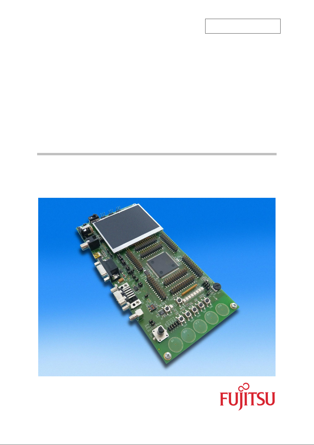
The SK-MB91590-208M04 is a multifunctional Starter-Kit for the FR81S 32-Bit MB91590
microcontroller series. It can be used stand-alone for software development and testing.
1.2 Features
9V external power supply
5V and 3.3V onboard voltage regulator
Power-on switch and Power-on indicator LED
All MCU pins routed to pin headers
4 MHz main crystal
On-Chip Debugging Interface
Voltage supervisor for 5V and 3.3V
Reset button (hard- and soft reset)
NMI interrupt button
5 Push-buttons
5 Capacitive Touch Buttons
Rotary Encoder
Potentiometer connected to A/D input
Ambient Light Sensor connected to A/D input
512 Mb (64Mbyte) External Flash Memory
QVGA (320x240) LCD Display with Backlight brightness control
Analog Video Input
FTDI converter
RS232 interface
LIN interface (shared with RS232 connector)
High speed CAN interface ver. 2.0
1 Miniature Loudspeaker
1 RGB LED
8 user LEDs
UG-910097-11 - 6 - © Fujitsu Semiconductor Europe GmbH

Chapter 1 Overview
1.3 General Description
The SK-MB91590-208M04 supports the MB91590 FR81S 32-bit Flash microcontroller series
with 208-pin 0.5 mm pitch package (FPT-208P-M04) such as the MB91F594BSPMC.
The SK-MB91590-208M04 can be used standalone to develop software programs.
The on-board voltage regulator allows a regulated external DC input of 9V on X2. The
regulated outputs of the board are 5V on J1 and 3.3V on J2. Both of these output voltages
are monitored by a voltage supervisor circuit which keeps the Microcontroller (MCU) in reset
until the 5V and 3.3V voltages stabilize.
The board is supplied with a 4 MHz crystal as main oscillation. With the internal PLL clock
multiplication system the maximum operation frequency of 80 MHz for the MB91590 series
can be reached.
For software development, the board includes a single wire on chip debugging (OCD)
interface used together with MB2100-01-E Embedded Emulator (optional). There is also a
Program/Run mode switch, SW1, to select programming or run mode. One on chip universal
asynchronous receiver transmitter (UART) is available to be connected via a RS232
transceiver to a 9 pin D-Sub connector (X14) or via a FTDI-chip to a mini USB connector
(X16). The MCU Internal Flash Memory can be programmed via both connectors, the 9 pin
D-Sub connector UART ‘A’ (X14) and the mini USB connector (X16).
One high-speed CAN interface (CAN protocol ver. 2.0) with a transfer speed up to 1Mbps is
routed out via a CAN transceiver to 9 pin D-Sub connector (X13). Alternatively, a LIN
transceiver is also routed via some jumpers to the D-Sub connector (X14).
The SK-MB91590-208M04 offers several modules for user interaction. The starter-kit has a
total of 7 push buttons: one for Reset, one for Non-Maskable-Interrupt (NMI) and 5 push
buttons connected to MCU’s external interrupt pins. There are five Capacitive Touch Buttons
connected to A/D inputs of the MCU for touch input evaluation. Similarly, a Potentiometer
and an Ambient Light Sensor are connected to the A/D input pins of the MCU. A Rotary
Encoder provides a quadrature signal output which is fed to the pins of Input Capture Unit of
the MCU. Eight user LEDs are connected to MCU’s General Purpose Input Output pins
(GPIO). One RGB LED can be controlled via PWM. Furthermore, a miniature Loudspeaker
is connected to the MCU via an audio amplifier circuit which takes input from the Sound
Generator module of the MCU.
For helping demonstrate the capabilities of Graphics Display Controller of the MB91F590
series, the starter-kit comes mounted with a QVGA 24bpp LCD Display. A 512Mb (64Mbyte)
External Flash Memory is interfaced to the MCU as a support for Graphics based
applications. The board also provides a video jack for Analog Video input.
Apart from External Flash Memory, QVGA 24bpp LCD Display and Miniature Loudspeaker,
all peripheral pins can be disconnected by the user using jumpers as explained later in this
document.
© Fujitsu Semiconductor Europe GmbH - 7 - UG-910097-11

1.4 Kit Contents
SK-MB91594-208M04 board
USB Cable
Additional Information page
Jumpers
Chapter 1 Overview
UG-910097-11 - 8 - © Fujitsu Semiconductor Europe GmbH
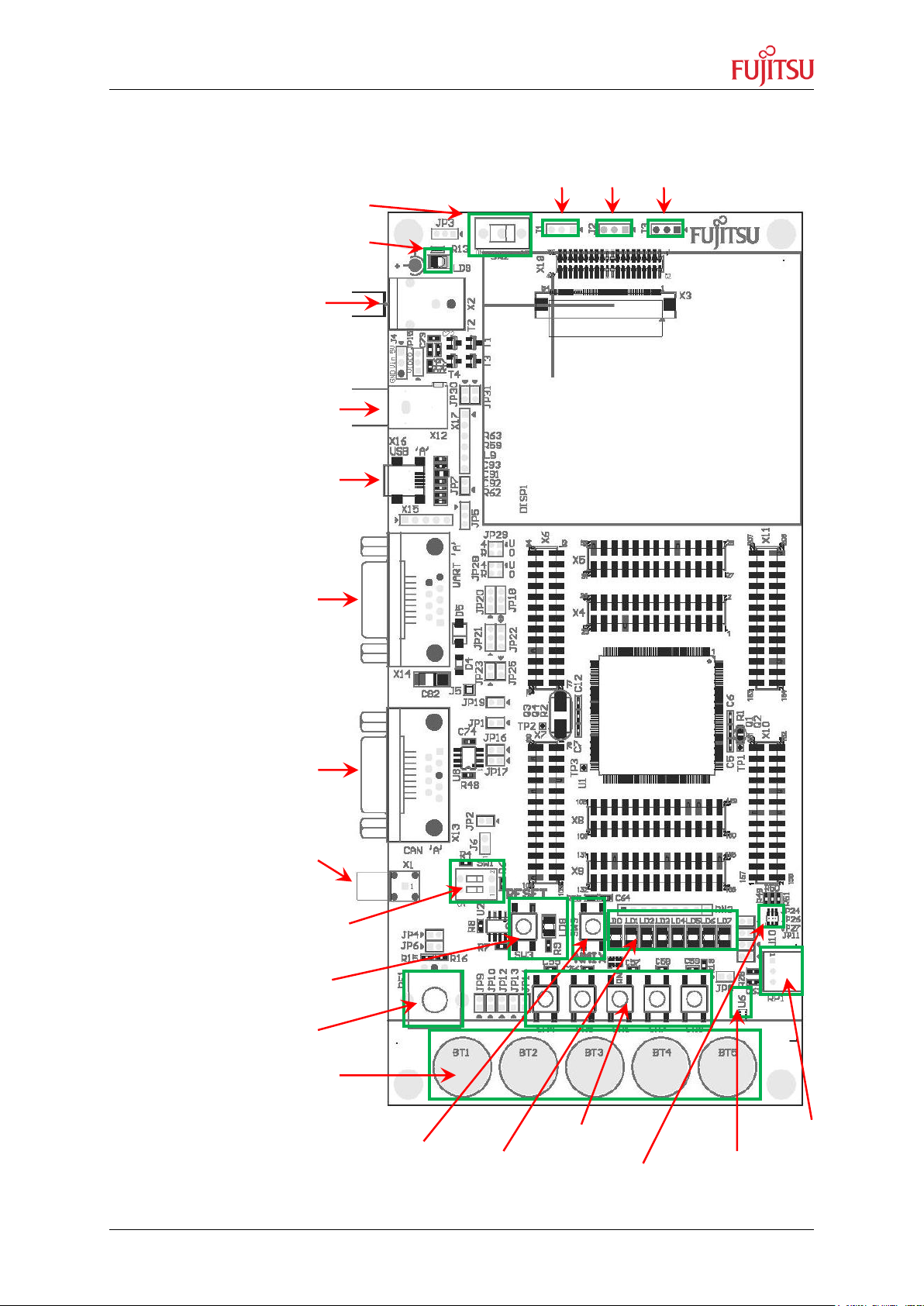
1.5 Board Overview
Ext. Power: 9V
Analog Video Input
UART ‘A’
CAN ‘A’
USB ‘A’
DEBUGIF
SMA connector
Program/Run Mode
Switch SW1
Ext. Power Switch SW2
Rotary Encoder RE1
Capacitive Touch Buttons
Power LED, LD9
Potentiometer RP1
Ambient Light
Sensor U6
RGB LED U10
Port LEDs
LD0...LD7
Push Buttons
SW4...SW8
NMI Interrupt
Button SW9
Reset button SW3 and
Reset LED LD8
5V
3V3
GND
Chapter 1 Overview
© Fujitsu Semiconductor Europe GmbH - 9 - UG-910097-11

Chapter 2 Installation
2 Installation
After opening the box, please check first if all parts are included. If any parts are missing,
ask your vendor.
After removing the packing-material, check all parts and especially the PCB for
damages. Also check the jumper-settings before initial powering up of the board.
For the power supply a DC input voltage of 9V is recommended. The positive voltage
(+) must be connected to the centre, and ground (GND) must be connected to the
shield of the connector X2!
After power-on, the green power-on LED for 3.3V (LD9) should light up. If the LED does not
light up, switch off the power supply and check input polarity as well as the setting of JP3.
The in-circuit programming allows the user to program own applications into the Flash
memory. The procedures for Flash programming are described in chapter 7.
UG-910097-11 - 10 - © Fujitsu Semiconductor Europe GmbH

Jumper
Description / Function
Type
Default
Setting
Location
Coordinates
JP1
MCU_AVR3
Jumper 2pin
Closed
F21
JP2
MCU_PWR (5V)
Jumper 2pin
Closed
E25
JP3
Power Supply - EXT/USB
Jumper 3pin
2-3
D1
JP4
Rotary Encoder Channel B
Jumper 2pin
Closed
C29
JP5
Display Backlight Enable Source
Jumper 3pin
2-3
E13
JP6
Rotary Encoder Channel A
Jumper 2pin
Closed
C30
JP7
Display Backlight Dimming
Jumper 2pin
Closed
E11
JP8
Ambient Light Sensor
Jumper 2pin
Closed
O31
JP9
Capacitive Button BT1
Jumper 2pin
Closed
E32
JP10
Capacitive Button BT2
Jumper 2pin
Closed
F32
JP11
Potentiometer
Jumper 2pin
Closed
P30
JP12
Capacitive Button BT3
Jumper 2pin
Closed
F32
JP13
Capacitive Button BT4
Jumper 2pin
Closed
G32
JP14
Capacitive Button BT5
Jumper 2pin
Closed
G32
JP15
Video Input Signal
Jumper 3pin
1-2
C6
JP16
CAN RX0
Jumper 2pin
Closed
F22
JP17
CAN TX0
Jumper 2pin
Closed
F22
JP18
LIN/UART RxD
Jumper 3pin
2-3
F16
JP19
RTS-CTS
Jumper 2pin
Open
F20
JP20
LIN/UART TxD
Jumper 3pin
2-3
F16
JP21
DTR/RTS
Jumper 3pin
1-2
F18
JP22
RS232/LIN
Jumper 3pin
1-2
F18
JP23
LIN Enable
Jumper 2pin
Open
F19
JP24
RGB LED (Red)
Jumper 2pin
Closed
P29
JP25
LIN Master Y/N
Jumper 2pin
Open
F19
JP26
RGB LED (Green)
Jumper 2pin
Closed
P29
JP27
RGB LED (Blue)
Jumper 2pin
Closed
P30
JP28
SIN
Jumper 4pin
U-4/R-0
F15
JP29
SOT
Jumper 4pin
U-4/R-0
F14
JP30
Display SPI-CLK
Jumper 2pin
Closed
E8
JP31
Display SPI-DAT
Jumper 2pin
Closed
E8
JP32
MCU_PWR (3V3)
Jumper 2pin
Closed
P14
Chapter 3 Default Jumper Settings
3 Default Jumper Settings
Check the board for following jumper settings before powering it up. Figure 1 on the next
page also shows the default jumper settings of the SK-MB91590-208M04.
© Fujitsu Semiconductor Europe GmbH - 11 - UG-910097-11
Table 1. Default Jumper Settings.
 Loading...