

Page 1
Fujitsu Electronics Europe
User Guide
FEEU-UG-2017120001-10
AMBIQ MICRO APOLLO 1 / 2
EVALUATION BOARD
SK-APOLLO-BASE
USER GUIDE
Page 2
FEEU Ultra-Low-Power Apollo Evaluation Kit Platform
Revision History
EEU-UG-2017120001-10 - 2 - © Fujitsu Electronics Europe GmbH
Revision History
Date
Issue
2017-12-04
V1.0, Manuel Schreiner, first version
This document contains 46 pages.
Page 3

FEEU Ultra-Low-Power Apollo Evaluation Kit Platform
Terms of use, Limited Warranty
© Fujitsu Electronics Europe GmbH - 3 - EEU-UG-2017120001-10
Terms of use, Limited Warranty
I. The use of the deliverables (e.g. software, application exam ples, target boards, evaluation
boards, starter kits , schematics, engineering s amples of IC’s etc.) is s ubject to th e conditions
of Fujitsu Electronics Europe GmbH (“FEEU”) as set out in (i) the terms of the License
Agreement and/or the Sale and Pur chase Agreement under which agreements the Product
has been delivered, (ii) the technical descriptions and (iii) all accompanying written materials.
II. Please note that the deliverables are intend ed for and must onl y be used for reference in a
test and evaluation laboratory environment. NO PRODUCTIVE OR PRIVATE USE
ALLOWED.
III. The software deliverables are provided on an as-is basis without charge. It is the user’s
obligation to full y test the software in its test environment, separated f rom a interconnected
productive environment, and to ensure proper f unctional ity, qualificat ion and co mpliance w ith
component specifications.
IV. Regarding hardware deliverables, FEEU warrants that they will be free from defects in
material and workmanship under or dinary, expected use and required s ervice as specif ied in
the accompanying written m aterials for a duration of 1 (one) year f rom the date of receipt by
the customer.
V. Should a hardware de liver a ble t urn o ut to be defect, FEEU’s ent ire lia bili t y and t h e c ust omer’s
exclusive remedy shall be, at FEEU´s sole discret ion, either return of the purchase price and
the license fee if an y, or replacem ent of the hardware deliverable or parts thereof. However,
this warranty is excluded if the defec t originates outs ide FEEU’s r esponsibilit y such as abuse
or misapplication attrib utable to the custom er or any other t hird party not re lating to FEEU or
to unauthorised decompiling and/or reverse engineering and/or disassembling.
VI. FEEU does not warrant that the deliverables do not infringe any third party intellectual
property right (IPR). In the event that the deliverables infringe a third party IPR the rem edies
listed in section V, VIII a nd IX apply. The customer is free to obtain necessary licenses to
continue the usage of the deliverable.
VII. In the event the software deliverables include the use of open source components, the
provisions of the go verning open source license a greement shall appl y with respect to such
software deliverables.
VIII. To the maximum extent permitted by applicable law FEEU disclaims all other warranties,
whether express or im plied, in particular , but not limited to, warranties of m erchantabilit y and
fitness for a particular purpose for which the deliverables are not designated.
IX. To the maximum ex tent permitted b y applicable law, F EEU’s liability is res tricted to inte ntion
and gross negligence. FEEU is not liable for consequential damages.
X. Should one of the above stipulations be or become invalid and/or unenforceable, the
remaining stipulations shall stay in full effect.
XI. The contents of this document are subject to change without a prior notice, thus contact
FEEU about the latest one.
XII. German law applies without the conf lict of law regulat ions. Place of venue is Frankf urt/Main,
Germany.
***
Fujitsu Electronics Europe GmbH
Page 4

FEEU Ultra-Low-Power Apollo Evaluation Kit Platform
Contents
EEU-UG-2017120001-10 - 4 - © Fujitsu Electronics Europe GmbH
Contents
REVISION HISTORY ................................................................................................................. 2
TERMS OF USE, LIMITED WARRANTY ................................................................................. 3
CONTENTS ............................................................................................................................... 4
0 FEEU APOLLO EVALUATION ............................................................................................ 6
1 INTRODUCTION SK-APOLLO-BASE ................................................................................. 8
1.1 Scope of delivery ......................................................................................................... 8
1.2 Overview ...................................................................................................................... 9
2 USING THE HARDWARE .................................................................................................. 10
2.1 The Breakout-Board .................................................................................................. 10
2.2 Getting started ........................................................................................................... 11
2.3 Power Measurement ................................................................................................. 13
2.3.1 On-Board Power Measurement .................................................................. 13
2.3.2 Power Measurement via external DVM ...................................................... 13
2.4 USB to Serial ............................................................................................................. 14
2.5 User Buttons .............................................................................................................. 16
2.5.1 Drive buttons via GPIO ................................................................................ 16
2.5.2 Drive buttons via IRQ .................................................................................. 17
2.6 RBG LED ................................................................................................................... 18
2.7 Arduino Headers ........................................................................................................ 19
2.7.1 Using Digital IO ............................................................................................ 20
2.7.2 Using ADC ................................................................................................... 21
2.7.3 Using PWM .................................................................................................. 22
2.7.4 Using SPI ..................................................................................................... 23
2.7.5 Using I2C ..................................................................................................... 25
3 CONNECTORS ................................................................................................................... 27
3.1 Jumpers ..................................................................................................................... 28
3.1.1 Apollo 1 Jumper Configuration .................................................................... 29
3.1.2 Apollo 2 Jumper Configuration .................................................................... 30
3.2 GPIO Connection ....................................................................................................... 31
3.2.1 Apollo 1 GPIO Connection .......................................................................... 31
3.2.2 Apollo 2 GPIO Connection .......................................................................... 32
3.3 Arduino Header .......................................................................................................... 33
3.3.1 Apollo 1 Arduino Header ............................................................................. 33
Page 5

FEEU Ultra-Low-Power Apollo Evaluation Kit Platform
Contents
© Fujitsu Electronics Europe GmbH - 5 - EEU-UG-2017120001-10
3.3.2 Apollo 2 Arduino Header ............................................................................. 35
4 APPENDIX .......................................................................................................................... 38
4.1 Schematics ................................................................................................................ 38
4.2 Figures ....................................................................................................................... 43
4.3 Index .......................................................................................................................... 44
5 INFORMATION IN THE WWW .......................................................................................... 45
6 RECYCLING ....................................................................................................................... 46
Page 6
FEEU Ultra-Low-Power Apollo Evaluation Kit Platform
FEEU APOLLO EVALUATION
EEU-UG-2017120001-10 - 6 - © Fujitsu Electronics Europe GmbH
0 FEEU APOLLO EVALUATION
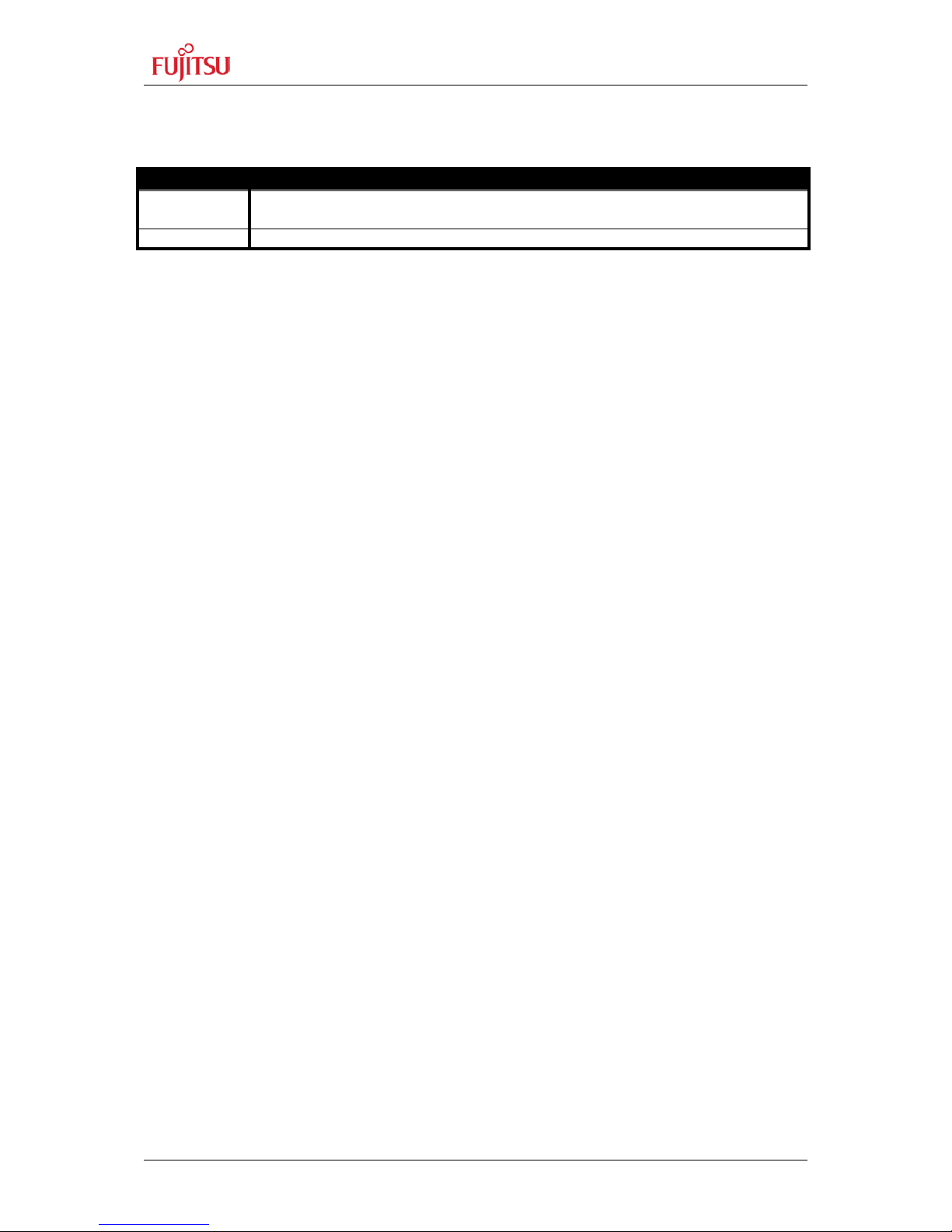
The Fujitsu Apollo Evaluation Platform is compatible with Ambiq Micro Apollo 1 or Apollo 2.
The platform consists of two parts: The br eakout b oard and the base board. The breakout
boards for Apollo 1 and Apollo 2 are pin-compatible but not totally functional compatibe.
Therefore only some jumper settings need adjustment to setup the base board for Apollo 1
or Apollo 2 usage.
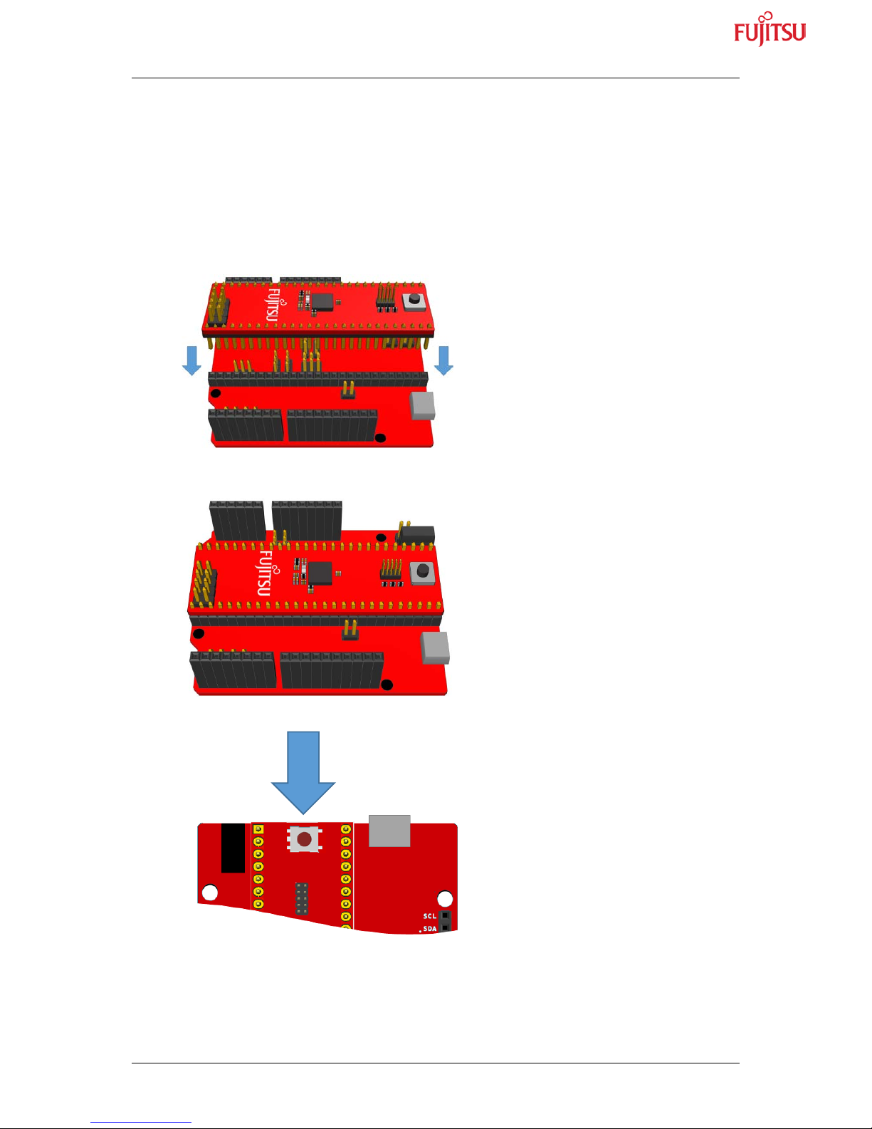
Both parts can easily plug together:
Page 7

FEEU Ultra-Low-Power Apollo Evaluation Kit Platform
FEEU APOLLO EVALUATION
© Fujitsu Electronics Europe GmbH - 7 - EEU-UG-2017120001-10
The Fujitsu Apollo Evaluation Platform includes a nano/micro power/energy measurement
probe to enable easy power measurement via PC without the need of an expensive multimeter or power probe. The on-board CMSIS-DAP compatible debugger works driverless
with common toolchains like IAR Workbench or ARM/Keil µVision, but is also supported by a
free-of-charge t oolchain iSys tem WinIDEA O pen. For additi onal communi cation to the P C,
the on-board CMSIS-DAP compatible chip “Fujitsu D-Bug” supports USB to UART
conversion.
The Fujitsu Evaluation Platform includes additional software examples (based on MCU
templates) to the Ambiq Micro’s SDK. It offers MCU Templates as a kind of a common
project framework or software framework needed for developers to have an easy start in
development with MCUs. Following IDEs are supported:
•
ARM (Keil μVision)
• Atollic (Atollic TrueStudio)
• Eclipse
• emIDE
•
iSYSTEM WinIDEA Open
•
IAR (IAR Embedded Workb
for ARM Cortex M)
• Makefile (GNU)
Page 8
FEEU Ultra-Low-Power Apollo Evaluation Kit Platform
Chapter 1 Introduction SK-APOLLO-BASE
EEU-UG-2017120001-10 - 8 - © Fujitsu Electronics Europe GmbH
1 Introduction SK-APOLLO-BASE
The SK-AMAPOLLO-BASE-V11 evaluation board includes a low-cost evaluation board
usable with FEEUs Ambiq Micro Apollo break-out boards SK-AMAP1-BREAKOUT-V11
(Apollo 1) and SK-AMAP2-BREAKOUT-V11 (Apollo 2).
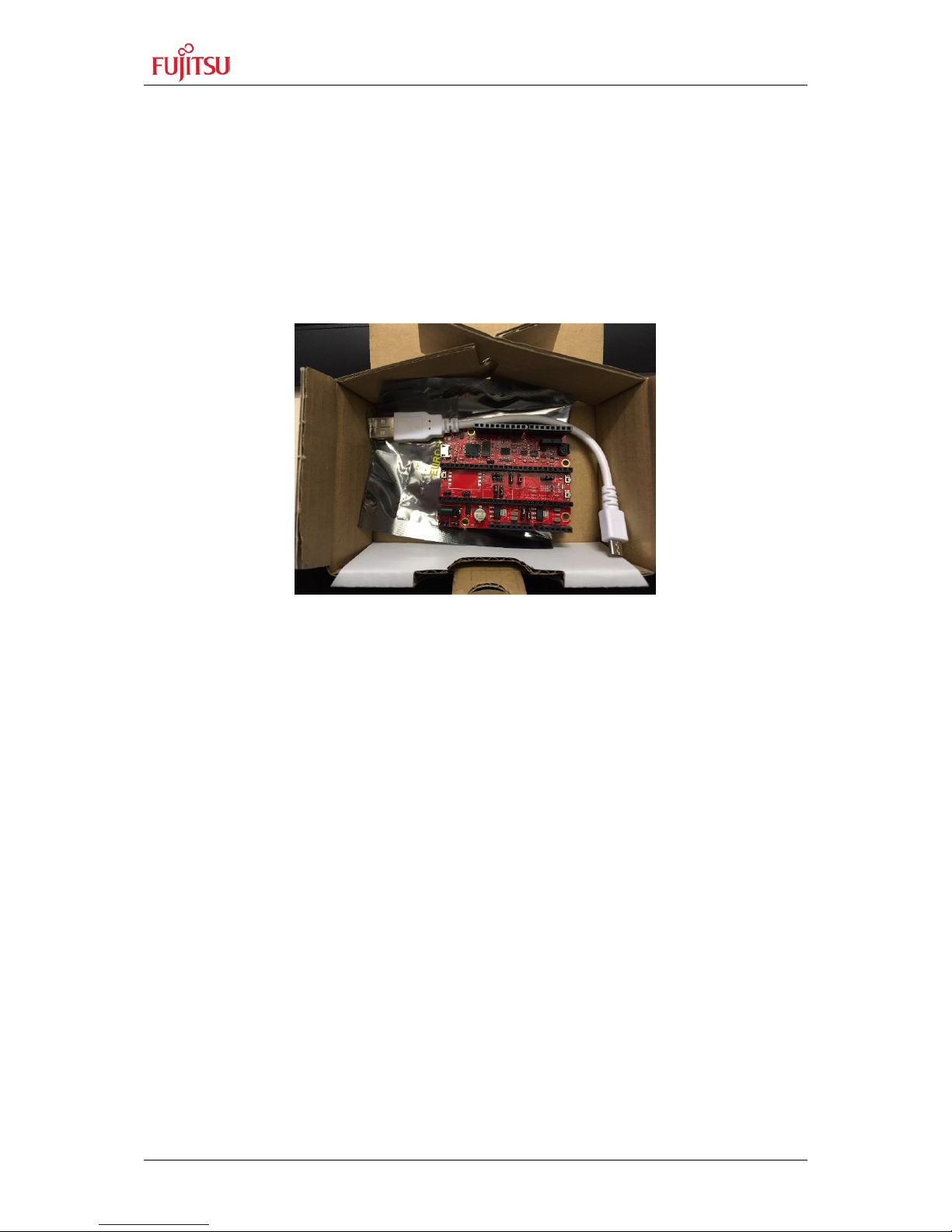
1.1 Scope of delivery
- Apollo base–board SK-AMAPOLLO-BASE-V11 in ESD bag
- USB-Mico cable
Not scope of delivery: SK-AMAP1-BREAKOUT-V11 / SK-AMAP2-BREAKOUT-V11
Page 9
FEEU Ultra-Low-Power Apollo Evaluation Kit Platform
Chapter 1 Introduction SK-APOLLO-BASE
© Fujitsu Electronics Europe GmbH - 9 - EEU-UG-2017120001-10
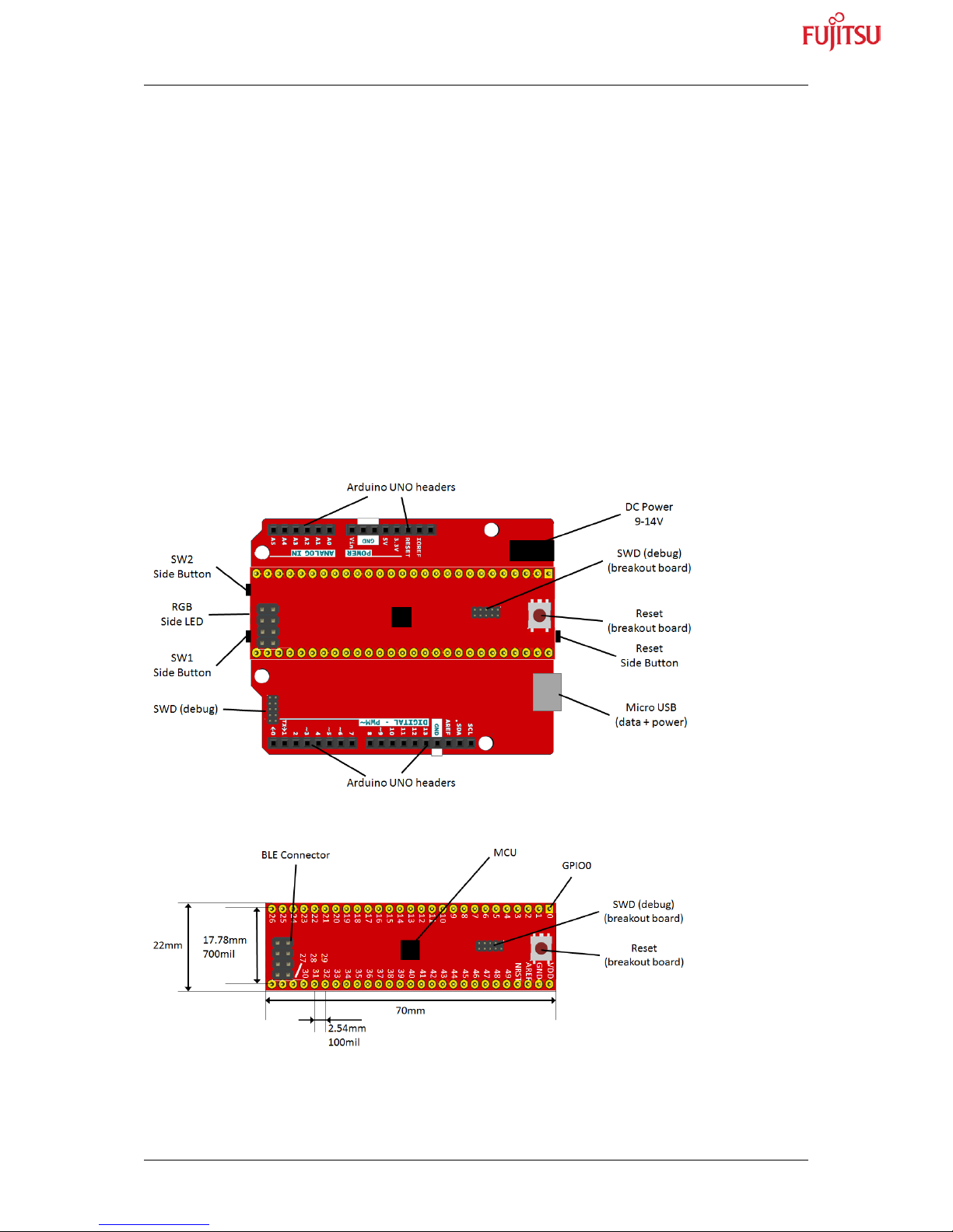
1.2 Overview
The SK-APOLLO-BASE is used with Apollo1 or Apollo2 breakout boards (not included).
After setting the jumpers for Apollo 1 or Apollo 2 usage the following features of the
baseboard can be used:
- Arduino UNO headers
o 5 Analo g pins (or digital pins)
o 16 digital pins
o I2C interface
o SPI int erface
- RGB LED
- 2 Buttons
- 1 Reset Button
- USB to Serial Wire Debug (SWD), CMSIS-DAP compatible
- USB to UART
- USB to power measurement
The breakout bo ar d i t s el f has an ad di t i o nal “ B LE ” co n n ect or where an e xt e r nal B LE c hi p can
be connected. For Apollo 1 only UART is supported by this connector. For Apollo 2 UART
and SPI can be used.
Figure 0-1: Overview EVK-Apollo-Baseboard
Figure 0-2: Apollo 1 / 2 Breakout-Board
Page 10
FEEU Ultra-Low-Power Apollo Evaluation Kit Platform
Chapter 2 Using the Hardware
EEU-UG-2017120001-10 - 10 - © Fujitsu Electronics Europe GmbH
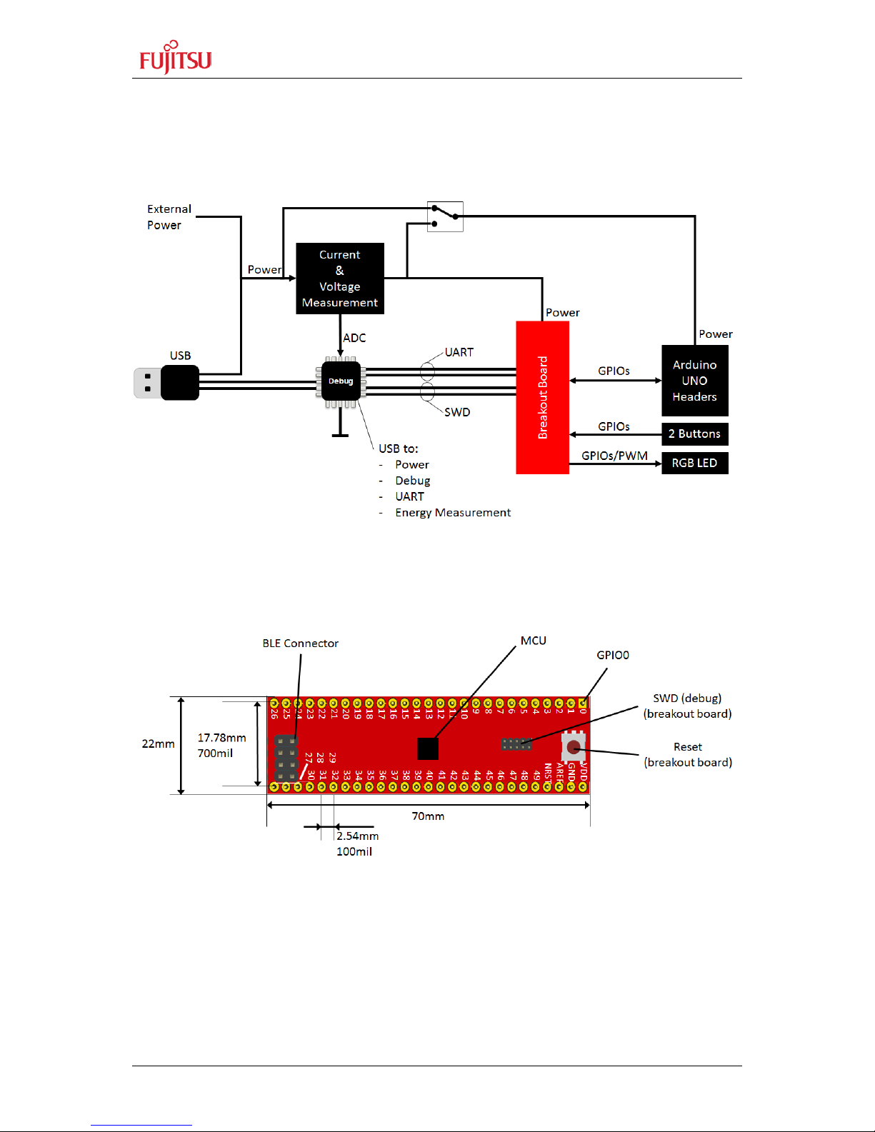
2 Using the Hardware
Following schematic gives a rough overview how the breakout board is connected to the
different functionalities:
Figure 1-1: FEEU EVK-Apollo-Baseboard Features
2.1 The Breakout-Board
The breakout-board has assembled:
- 2x 27pin 2.54mm header: 50GPIOs, NRST, AREF, GND and VCC
- MCU (A pollo 1 or Apollo 2)
- Inductors for the DC/DC converter
- 32.768 KHz crystal
- ADC filter network
- Reset button
- SWD connector (Debug)
Page 11
FEEU Ultra-Low-Power Apollo Evaluation Kit Platform
Chapter 2 Using the Hardware
© Fujitsu Electronics Europe GmbH - 11 - EEU-UG-2017120001-10
- BLE connector (Apollo 1 UART only, Apollo 2 UART and SPI)
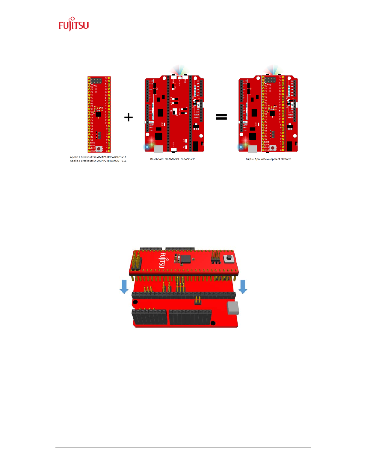
2.2 Getting started
(1) Check the jumpers as descr ibed in 2.1 Jumpers depending of the s electe d Apollo 1
or Apollo 2 break out board.
(2) Insert the breakout board with the RESET button in direction of the Power / USB
connector.
Figure 1-2: Breakout-Board Orientation
Page 12

FEEU Ultra-Low-Power Apollo Evaluation Kit Platform
Chapter 2 Using the Hardware
EEU-UG-2017120001-10 - 12 - © Fujitsu Electronics Europe GmbH
(3) Connect your board via the USB connector to power the EVK
a. LED LD3 (blue) should turn on
b. After a few seconds LED LD2 should start fading RED
Figure 1-3: USB Connection
(4) Installing Drivers
a. For Linux n o drivers are needed
b. For OS X no drivers are needed
c. For Windows 10 no drivers are needed
d. For Windows XP – 8 please download the driver package from the FEEU
website
(5) Installing software (IDE)
a. iSYSTEM WinIDEA Open (free of charge)
i. http://www.isystem.com/download/winideaopen
b. Atollic TrueStudio (free of charge / commercial)
i. https://atollic.com/resources/download/
c. IAR Embedded Workbench (commercial)
i. EWARM 30-day Ev aluation Version
http://supp.iar.com/Download/SW/?item=EWARM-EVAL
ii. EWARM 32K Kickstart Version
http://supp.iar.com/Download/SW/?item=EWARM-KS32
d. Keil µVision / ARM MDK (commercial)
i. Evaluation Version
https://www.keil.com/demo/eval/arm.htm
Page 13

FEEU Ultra-Low-Power Apollo Evaluation Kit Platform
Chapter 2 Using the Hardware
© Fujitsu Electronics Europe GmbH - 13 - EEU-UG-2017120001-10
2.3 Power Measurement
2.3.1 On-Board Power Measurement
The on-board debug probe is supporting power measurement. Currently the firmware is still
in development and will be supported by the latest ARM MDK / Keil µVison.
The FujitsuLink_PowerMeasurement tool can be used to visualize the power consumption
without any DVM required.
2.3.2 Power Measurement via external DVM
Connect an external Multimeter to JP3 pin 2 (+) and 3 (-) to measure the current
consumption of the MCU.
Figure 1-4: External DVM Connection
To measure also the power consumption of components at the Arduino shield, set JP16 to 23 position
Figure 1-5: Include Arduino-Header in Power Measurement
Page 14
FEEU Ultra-Low-Power Apollo Evaluation Kit Platform
Chapter 2 Using the Hardware
EEU-UG-2017120001-10 - 14 - © Fujitsu Electronics Europe GmbH
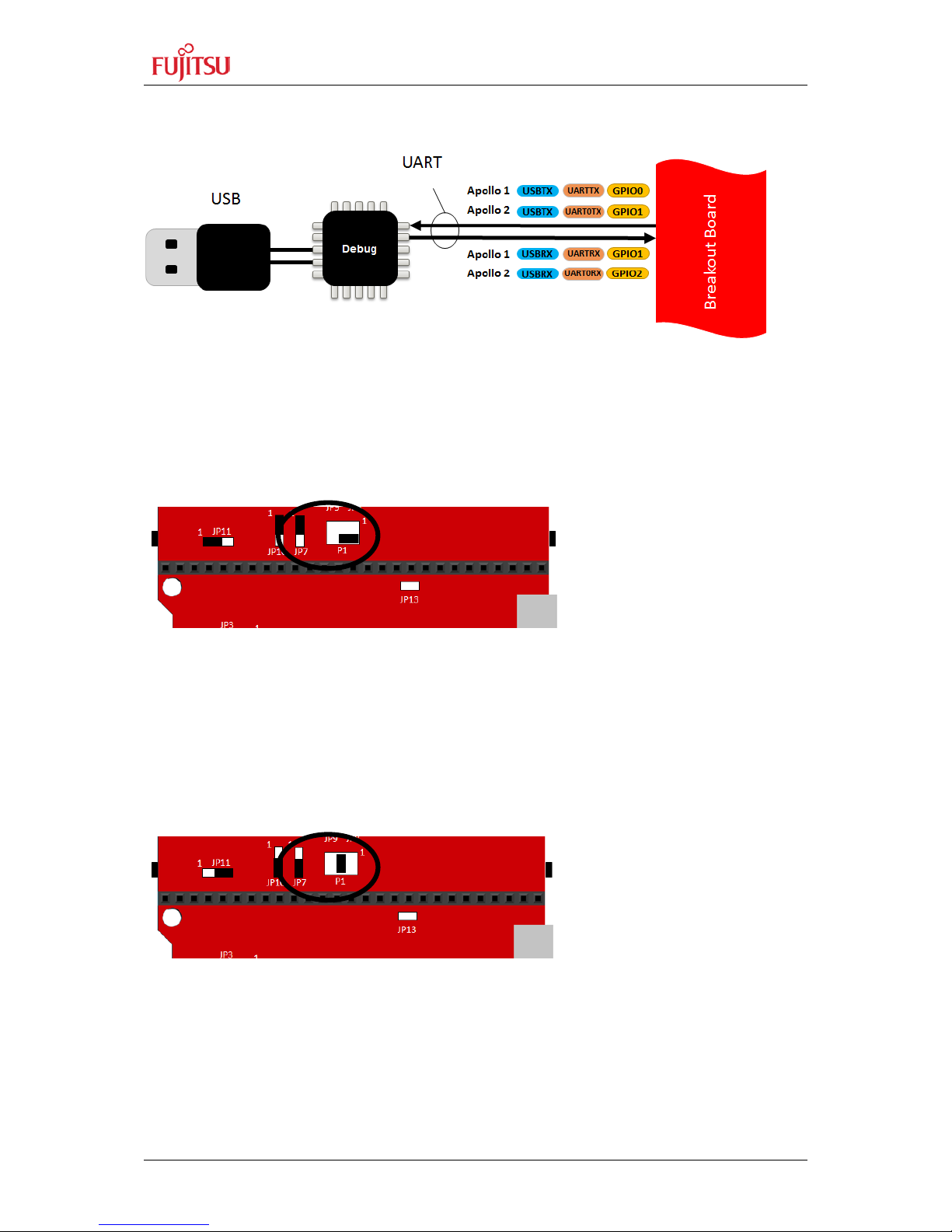
2.4 USB to Serial
Figure 1-6: USB to UART Converter
To use the USB to serial converter, several serial options are possible. For UART the
jumpers JP7 and P1 are used to set the correct u sage.
For Apollo 1, JP7 must be 1-2 and P1 2-4:
Figure 1-7: Apollo 1 jumper configuration for UART usage
With this jumper selection, GPIO0 is UARTTX and GPIO1 UARTRX.
For Apollo 2, JP7 must be 2-3 and P1 3-4:
Figure 1-8: Apollo 2 jumper configuration for UART usage
With this jumper selection, GPIO1 is UARTTX and GPIO2 UARTRX.
Page 15

FEEU Ultra-Low-Power Apollo Evaluation Kit Platform
Chapter 2 Using the Hardware
© Fujitsu Electronics Europe GmbH - 15 - EEU-UG-2017120001-10
Start with the FEEU MCU Temlate for Apollo 1 or Apollo 2. Enable UART FEEU Low-LevelDriver for Apollo in RTE_Device.h (in example\source\config):
Add apollouart.c and apollogpio.c to your pr o j ec t a n d inc l u de apollouart.h and apollogpio.h in
you C-file. Following code gives an example how to poll the UART:
#define APOLLOUART_ENABLED 1
#define APOLLOGPIO ENABLED 1
#include "mcu.h"
#include "apollogpio.h"
#include "apollouart.h"
#ifdef APOLLO2_H
#define UART UART1
#endif
int main(void)
{
char c;
#ifdef APOLLO2_H
ApolloGpio_GpioSelectFunction(PIN_GPIO1,2); //use UART at GPIO1
ApolloGpio_GpioSelectFunction(PIN_GPIO2,2); //use UART at GPIO2
#else
ApolloGpio_GpioSelectFunction(PIN_GPIO0,2); //use UART at GPIO0
ApolloGpio_GpioSelectFunction(PIN_GPIO1,2); //use UART at GPIO1
#endif
ApolloUart_Init(UART,115200);
ApolloUart_PutString(“Hello World!\r\n”);
while(1)
{
if (ApolloUart_HasChar(UART)) //button SW1 is pressed
{
c = ApolloUart_GetChar(UART);
ApolloUart_PutChar(UART,c);
}
}
}
Page 16

FEEU Ultra-Low-Power Apollo Evaluation Kit Platform
Chapter 2 Using the Hardware
EEU-UG-2017120001-10 - 16 - © Fujitsu Electronics Europe GmbH
2.5 User Buttons
User buttons are connected as followed:
Figure 1-9: Buttons SW1 and SW2 at EVK-Apollo-Base
SW1 connects to GPIO28 and SW2 to GPIO17.
2.5.1 Drive buttons via GPIO
Start wi th the F EEU MC U Teml ate for Apollo 1 or Apol lo 2. E nable GPIO FEEU Low-LevelDriver for Apollo in RTE_Device.h (in example\source\config):
Add apollogpio.c to your projec t an d incl ude apollogpio.h in you C-file. Following code gives
an example how to poll the GPIO:
#define APOLLOGPIO ENABLED 1
#include "mcu.h"
#include "apollogpio.h"
int main(void)
{
ApolloGpio_GpioInputEnable(PIN_GPIO28,TRUE); //set GPIO28
//to input
ApolloGpio_GpioInputEnable(PIN_GPIO17,TRUE); //set GPIO17
//to input
while(1)
{
if (ApolloGpio_GpioIsSet(PIN_GPIO28)) //button SW1 is pressed
{
//do the script executing code
}
}
Page 17

FEEU Ultra-Low-Power Apollo Evaluation Kit Platform
Chapter 2 Using the Hardware
© Fujitsu Electronics Europe GmbH - 17 - EEU-UG-2017120001-10
2.5.2 Drive buttons via IRQ
Start with the FEEU MCU Teml ate for Apoll o 1 or Apo llo 2. E nable G PIO FE EU Low-LevelDriver for Apollo in RTE_Device.h (in example\source\config):
Add apollogpio.c to your projec t an d incl ude apollogpio.h in you C-file. Following code gives
an example how to use GPIOs with callbacks:
#define APOLLOGPIO ENABLED 1
#include "mcu.h"
#include "apollogpio.h"
static volatile boolean_t bSw1CallbackHappened = FALSE;
void Sw1_Callback(uint8_t u8Gpio)
{
bSw1CallbackHappened = TRUE;
}
int main(void)
{
ApolloGpio_RegisterIrq(PIN_GPIO28,
GpioFallingEdge,
Sw1_Callback); //set GPIO28 to IRQ usage
NVIC_ClearPendingIRQ(GPIO_IRQn); //clear pending flag
NVIC_EnableIRQ(GPIO_IRQn); //enable IRQ
NVIC_SetPriority(GPIO_IRQn,1); //set priority of IRQ
//smaller value means
//higher priority
while(1)
{
if (bSw1CallbackHappened) //button SW1 is pressed
{
bSw1CallbackHappened = FALSE;
//do the script executing code
}
}
Page 18

FEEU Ultra-Low-Power Apollo Evaluation Kit Platform
Chapter 2 Using the Hardware
EEU-UG-2017120001-10 - 18 - © Fujitsu Electronics Europe GmbH
2.6 RBG LED
The user RGB LED is connect ed as followed:
Figure 1-10: RGB LED at EVK-Apollo-Base
Start with the FEEU MCU T emlate for Apollo 1 or A pollo 2. Enable CTIMER FEEU LowLevel-Driver for Apollo in RTE_Device.h (in example\source\config):
Add apolloctimer.c to your pr oject and inc lude apolloctimer.h in y ou C-file. Following code
gives an example how to use a PWM to dim a LED:
#include "mcu.h"
#include "apollogctimer.h"
int main(void)
{
ApolloCTimer_PwmInitByGpio(PIN_GPIO42,TRUE); //set GPIO42
//to PWM
ApolloCTimer_PwmInitByGpio(PIN_GPIO43,TRUE); //set GPIO43
//to PWM
ApolloCTimer_PwmInitByGpio(PIN_GPIO46,TRUE); //set GPIO46 to
PWM
ApolloCTimer_PwmSetDutyByGpio(42,0.5f); //set red LED to
//50% duty cycle
while(1)
{
__NOP();
}
}
#define APOLLOCTIMER_ENABLED 1
#define APOLLOGPIO_ENABLED 1
Page 19

FEEU Ultra-Low-Power Apollo Evaluation Kit Platform
Chapter 2 Using the Hardware
© Fujitsu Electronics Europe GmbH - 19 - EEU-UG-2017120001-10
2.7 Arduino Headers
Arduin o functi ons can be used by just selecting the pin in the way A RDUINO_<FUNCTI ON>.
Example:
Function A0: ARDUINO_A0, PIN_GPIO12 (for Apollo 1), PIN_GPIO16 (for Apollo 2)
Function RXD: ARDUINO_D0 or ARDUINO_RXD, PIN_GPIO36
Function SS: ARDUINO_D10, ARDUINO_SS, PIN_GPIO27
Function SDA: ARDUINO_D18, ARDUINO_SDA, PIN_GPIO6
A complete list is attached:
Arduino
Function
Description
Apollo 1
Apollo 2
Default Function
Default Function
NC not connected
IOREF
IO reference voltage
RESET
Reset
3.3V
3.3V
bold marked:
bold marked:
5V 5V
differences between
differences between
GND
GND
Apollo 1 / Apollo 2
Apollo 1 / Apollo 2
GND
GND
Vin Vin
A0
A0
GPIO or Analogport A0
GPIO12/ADC0
GPIO16/ADCSE0
A1
A1
GPIO or Analogport A1
GPIO13/ADC1
GPIO34/ADCSE6
A2
A2
GPIO or Analogport A2
GPIO14/ADC2
GPIO11/ADCSE2
A3
A3
GPIO or Analogport A3
GPIO31/ADC6
GPIO31/ADCSE3
A4
A4
GPIO or Analogport A4
GPIO32/ADC7
GPIO32/ADCSE4
A5
A5
GPIO or Analogport A5
GPIO30/ADC5
GPIO33/ADCSE5
0/RXD
D0 or RXD
GPIO or UART RXD
GPIO36/UARTRX
GPIO36/UART1RX
1/TXD
D1 or TXD
GPIO or UART TXD
GPIO35/UARTTX
GPIO35/UART1TX
2
D2
GPIO or PWM0
GPIO25/TCTA0
GPIO25/TCTA0
3
D3
GPIO or PWM1
GPIO26/TCTB0
GPIO26/TCTB0
4
D4
GPIO or PWM2
GPIO18/TCTA1
GPIO18/TCTA1
5
D5
GPIO or PWM3
GPIO19/TCTB1
GPIO19/TCTB1
6
D6
GPIO or PWM4
GPIO46/TCTA2
GPIO46/TCTA2
7
D7
GPIO or PWM5
GPIO47/TCTB2
GPIO47/TCTB2
8
D8
GPIO or PWM6
GPIO48/TCTA3
GPIO48/TCTA3
9
D9
GPIO or PWM7
GPIO49/TCTB3
GPIO49/TCTB3
10/SS
D10 or SS
GPIO or Chipselect
GPIO27/M1nCE4
GPIO27/M1nCE4
11/MOSI
D11 or MOSI
GPIO or SPI MOSI
GPIO10/M1MOS
GPIO10/M1MOS
12/MISO
D12 or MISO
GPIO or SPI MISO
GPIO9/M1MISO
GPIO9/M1MISO
13/SCK
D13 or SCK
GPIO or SPI SCK
GPIO8/M1SCL
GPIO8/M1SCL
GND
GND
AREF
Analog Reference
GPIO16
18/SDA
D18 or SDA
GPIO or I2C SDA
GPIO6/M0SDA
GPIO6/M0SDA
19/SCL
D19 or SCL
GPIO or I2C SCL
GPIO5/M0SCL
GPIO5/M0SCL
Page 20

FEEU Ultra-Low-Power Apollo Evaluation Kit Platform
Chapter 2 Using the Hardware
EEU-UG-2017120001-10 - 20 - © Fujitsu Electronics Europe GmbH
2.7.1 Using Digital IO
Digital IOs are available as A0…5 and D0..D13 and D18..19. Digital IOs can be also directly
addressed by using GPIO0..49.
The Naming is: ARDUINO_A<x>, ARDUINO_D<y> or PIN_GPIO<z>
Start wi th the F EEU MC U Teml ate for Apollo 1 or Apol lo 2. E nable G PIO FEE U Low-Level-
Driver for Apollo in RTE_Device.h (in example\source\config):
Add apollogpio.c to yo ur project and i nclude apollogpio.h and skamapollobase.h in you C-
file. Following code gives an example how to poll the GPIO:
#define APOLLOGPIO ENABLED 1
#include "mcu.h"
#include "skamapollobase.h"
#include "apollogpio.h"
int main(void)
{
ApolloGpio_GpioInputEnable(ARDUINO_D0,TRUE);
ApolloGpio_GpioOutputEnable(ARDUINO_D1,TRUE);
while(1)
{
if (ApolloGpio_GpioIsSet(ARDUINO_D0))
{
ApolloGpio_GpioSet(ARDUINO_D1);
}
else
{
ApolloGpio_GpioClear(ARDUINO_D1);
}
}
}
Page 21

FEEU Ultra-Low-Power Apollo Evaluation Kit Platform
Chapter 2 Using the Hardware
© Fujitsu Electronics Europe GmbH - 21 - EEU-UG-2017120001-10
2.7.2 Using ADC
Digita l IOs are av ailable as A0…5.
The Naming is: ARDUINO_A<n>
Start wi th the F EEU MC U Teml ate for Apollo 1 or Apol lo 2. E nable G PIO FEE U Low-Level-
Driver for Apollo in RTE_Device.h (in example\source\config):
Add apollogpio.c and apolloadc.c to your project and include apolloadc.h and
skamapollobase.h in you C-file. Following code gives an example how to poll the ADC:
#define APOLLOADC_ENABLED 1
#define APOLLOGPIO_ENABLED 1
#include "mcu.h"
#include "skamapollobase.h"
#include "apolloadc.h"
int main(void)
{
float32_t f32AdcValue = 0.0f;
while(1)
{
f32AdcValue = ApolloAdc_SimpleReadByPin(ARDUINO_A0);
}
}
Page 22

FEEU Ultra-Low-Power Apollo Evaluation Kit Platform
Chapter 2 Using the Hardware
EEU-UG-2017120001-10 - 22 - © Fujitsu Electronics Europe GmbH
2.7.3 Using PWM
Start with the FEEU MCU T emlate for Apollo 1 or Apollo 2. Enable CTIMER FEEU LowLevel-Driver for Apollo in RTE_Device.h (in example\source\config):
Add apolloctimer.c to yo ur project a nd include apolloctimer.h and skamapollobase.h i n you
C-file. Following code gives an example how to use a PWM at D2:
#define APOLLOCTIMER_ENABLED 1
#define APOLLOGPIO_ENABLED 1
#include "mcu.h"
#include "skamapollobase.h"
#include "apollogctimer.h"
int ain(void)
{
ApolloCTimer_PwmInitByGpio(ARDUINO_D2,TRUE);
ApolloCTimer_PwmSetDutyByGpio(ARDUINO_D2,0.5f);//set red LED to
//50% duty cycle
while(1)
{
__NOP();
}
}
Page 23

FEEU Ultra-Low-Power Apollo Evaluation Kit Platform
Chapter 2 Using the Hardware
© Fujitsu Electronics Europe GmbH - 23 - EEU-UG-2017120001-10
2.7.4 Using SPI
Start w ith the FEE U MCU T emlate f or Apollo 1 or Apollo 2. Enable IOM FEEU Low-LevelDriver for Apollo in RTE_Device.h (in example\source\config):
#define IOMSTR1_ENABLED 1
#define APOLLOGPIO_ENABLED 1
Page 24

FEEU Ultra-Low-Power Apollo Evaluation Kit Platform
Chapter 2 Using the Hardware
EEU-UG-2017120001-10 - 24 - © Fujitsu Electronics Europe GmbH
Add apolloiom.c to your project and include apolloiom.h and skamapollobase.h in you C-file.
Following code gives an example how to use the IOM:
#incude "mcu.h"
#include "skamapollobase.h"
#include "apolloiom.h"
#include "apollogpio.h"
const stc_apolloiom_config_t stcIomConfig = {
IomInterfaceModeSpi, //use SPI mode
15000000UL, //frequency
FALSE, //SPHA setting
FALSE, //SPOL setting
0, //WriteThreshold
60 //ReadThreshold
};
int main(void)
{
uint8_t b = 0xAA;
ApolloIOM_Configure(IOMSTR1,&stcIomConfig);
ApolloIOM_Enable(IOMSTR1);
ApolloGpio_GpioOutputEnable(ARDUINO_SS,TRUE);
CLEAR_GPIO(ARDUINO_SS); //set chipselect
//send one byte
ApolloIom_SpiWriteByte(IOMSTR1, 0, b, AM_HAL_IOM_RAW);
//read one byte
b = ApolloIom_SpiReadByte(IOMSTR1, 0, AM_HAL_IOM_RAW);
SET_GPIO(ARDUINO_SS); //clear chipselect
while(1)
{
__NOP();
}
}
Page 25

FEEU Ultra-Low-Power Apollo Evaluation Kit Platform
Chapter 2 Using the Hardware
© Fujitsu Electronics Europe GmbH - 25 - EEU-UG-2017120001-10
2.7.5 Using I2C
Start w ith the FEE U MCU T emlate f or Apollo 1 or Apollo 2. Enable IOM FEEU Low-LevelDriver for Apollo in RTE_Device.h (in example\source\config):
#define IOMSTR0_ENABLED 1
#define APOLLOGPIO_ENABLED 1
Page 26

FEEU Ultra-Low-Power Apollo Evaluation Kit Platform
Chapter 2 Using the Hardware
EEU-UG-2017120001-10 - 26 - © Fujitsu Electronics Europe GmbH
Add apolloiom.c to your project and include apolloiom.h and skamapollobase.h in you C-file.
Following code gives an example how to use the IOM:
#incude "mcu.h"
#include "skamapollobase.h"
#include "apolloiom.h"
#include "apollogpio.h"
const stc_apolloiom_config_t stcIomConfig = {
IomInterfaceModeI2C, //use SPI mode
400000UL, //frequency
FALSE, //SPHA setting
FALSE, //SPOL setting
0, //WriteThreshold
60 //ReadThreshold
};
int main(void)
{
uint8_t b = 0xAA;
ApolloIOM_Configure(IOMSTR1,&stcIomConfig);
ApolloIOM_Enable(IOMSTR1);
ApolloGpio_GpioPullupEnable(BOARD_I2C_SCL_PIN,TRUE);
ApolloGpio_GpioPullupEnable(ARDUINO_SDA,TRUE);
ApolloGpio_GpioSelectPullup(ARDUINO_SCL,PullUp6K);
ApolloGpio_GpioSelectPullup(ARDUINO_SDA,PullUp6K);
ApolloGpio_GpioInputEnable(ARDUINO_SCL,TRUE);
ApolloGpio_GpioInputEnable(ARDUINO_SDA,TRUE);
ApolloGpio_GpioSelectFunction(ARDUINO_SCL _PIN,
ARDUINO_SCL_FUNC);
ApolloGpio_GpioSelectFunction(ARDUINO_SDA,
ARDUINO_SDA_FUNC);
// Writing 1 byte data for address 5, register 0x11
ApolloIom_I2CWriteRegister(IOMSTR1,0x05,0x11,&b,1);
// Reading 1 byte data for address 5, register 0x11
ApolloIom_I2CReadRegister(IOMSTR1,0x05,0x11,&b,1);
while(1)
{
__NOP();
}
}
Page 27

FEEU Ultra-Low-Power Apollo Evaluation Kit Platform
Chapter 3 Connectors
© Fujitsu Electronics Europe GmbH - 27 - EEU-UG-2017120001-10
3 Connectors
Note:
All data and power supply lines connected to this starter kit should be kept as
short as possible, with a maximum allowable length of 3m. Shielded cables
should be used for data lines. As a rule of thumb, the cable length used when
connecting external circuitry to the MCU pin header connectors for example
should be less than 20cm. Longer cables may affect EMC performance and
cause radio interferen ce.
Page 28

FEEU Ultra-Low-Power Apollo Evaluation Kit Platform
Chapter 3 Connectors
EEU-UG-2017120001-10 - 28 - © Fujitsu Electronics Europe GmbH
3.1 Jumpers
Jumper
Description
Default
Options
JP6 Set the power source 2-3
1-2: Power via DC-in
2-3: Power via Debug-USB-Port
JP1
Remove for VBAT usage
closed
Open for VBAT usage
JP10
Arduino A1 Selection
Apollo1: 1-2
Apollo2: 2-3
1-2 GPI013/ADC1 (Apollo)
2-3 GPI037/ADC6 (Apollo 2)
JP10
Arduino A5 Selection
Apollo1: 1-2
Apollo2: 2-3
1-2 GPI030/ADC5 (Apollo)
2-3 GPI033/ADC5 (Apollo 2)
JP12
Solder Jumper, SWDCLK
closed
JP13
Debugger Program Mode
open
closed: start in USB programming mode
JP14
Solder Jumper, SWO
closed
JP15
Solder Jumper, Reset
closed
JP16
Select power delivery
Arduino headers
1-2
1-2: Direct via 3.3V
2-3: Include to power measurement
JP17
RGB LED (Red)
closed
JP18
RGB LED (Red)
closed
JP19
RGB LED (Red)
closed
JP2
Solder Jumper, SWDIO
closed
JP3
Select current probe
1-2,3-4
1-2,3-4: Current probe via shunt
2-3: No current Measurement, no shunt
JP4
Debugger I2C and SPI mode
open
closed in I2C and SPI mode
JP5
Debugger SPI mode
open
closed in SPI mode
JP7
Debugger Apollo 1 / 2 UART
mode
Apollo1: 1-2
Apollo2: 2-3
Apollo: 1-2 I2C, UART
Apollo 2: 1-2 I2C, SPI-Master
Apollo: 2-3 SPI-Slave
Apollo 2: 2-3 SPI-Slave, UART
JP8
Arduino A2 Selection
Apollo1: 1-2
Apollo2: 2-3
1-2 GPI014/ADC2 (Apollo)
2-3 GPI011/ADC2 (Apollo 2)
JP9
Arduino A0 Selection
Apollo1: 1-2
Apollo2: 2-3
1-2 GPI012/ADC0 (Apollo)
2-3 GPI016/ADC0 (Apollo 2)
P1
Debugger Apollo 1 / 2 UART
mode
Apollo: 2-4 UART
Apollo 2: 3-4 UART
Apollo: 3-4 SPI, 2-4 UART
Apollo 2: 3-4 SPI-Slave, 3-4 UART, 4-6 SPI-Master
Page 29

FEEU Ultra-Low-Power Apollo Evaluation Kit Platform
Chapter 3 Connectors
© Fujitsu Electronics Europe GmbH - 29 - EEU-UG-2017120001-10
3.1.1 Apollo 1 Jumper Configuration
Page 30

FEEU Ultra-Low-Power Apollo Evaluation Kit Platform
Chapter 3 Connectors
EEU-UG-2017120001-10 - 30 - © Fujitsu Electronics Europe GmbH
3.1.2 Apollo 2 Jumper Configuration
Page 31

FEEU Ultra-Low-Power Apollo Evaluation Kit Platform
Chapter 3 Connectors
© Fujitsu Electronics Europe GmbH - 31 - EEU-UG-2017120001-10
3.2 GPIO Connection
3.2.1 Apollo 1 GPIO Connection
GPIO
Usage
GPIO
Usage
GPIO0
Debugger SCL / SCK / RXD
GPIO37
-
GPIO1
Debugger SDA / MOSI / TXD
GPIO38
-
GPIO2
Debugger MISO
GPIO39
BLE Connector UARTTX
GPIO3
Debugger CS
GPIO40
BLE Connector UARTRX
GPIO4
BLE Connector PWR
GPIO41
Debug - SWO
GPIO5
Arduino pin 19, I2C SCL
GPIO42
RGB LED - Red
GPIO6
Arduino pin 19, I2C SDA
GPIO43
RGB LED - Green
GPIO7
-
GPIO44
BLE Connector
GPIO8
Arduino pin 13, SPI SCK
GPIO45
RGB LED - Blue
GPIO9
Arduino pin 12, SPI MISO
GPIO46
Arduino pin 6
GPIO10
Arduino pin 11, SPI MOSI
GPIO47
Arduino pin 7
GPIO11
-
GPIO48
Arduino pin 8
GPIO12
Arduino A0
GPIO49
Arduino pin 9
GPIO13
Arduino A1
GPIO14
Arduino A2
GPIO15
-
GPIO16
-
GPIO17
Button SW2
GPIO18
Arduino pin 4
GPIO19
Arduino pin 5
GPIO20
Debug - SWDCLK
GPIO21
Debug - SWDIO
GPIO22
-
GPIO23
BLE Connector
GPIO24
BLE Connector
GPIO25
Arduino pin 2
GPIO26
Arduino pin 3
GPIO27
Arduino pin 10, SPI CS
GPIO28
Button SW1
GPIO29
BLE Connector
GPIO30
Arduino A5
GPIO31
Arduino A3
GPIO32
Arduino A4
GPIO33
-
GPIO34
-
GPIO35
Arduino pin 1, UART TX
GPIO36
Arduino pin 0, UART RX
Page 32

FEEU Ultra-Low-Power Apollo Evaluation Kit Platform
Chapter 3 Connectors
EEU-UG-2017120001-10 - 32 - © Fujitsu Electronics Europe GmbH
3.2.2 Apollo 2 GPIO Connection
GPIO
Usage
GPIO
Usage
GPIO0
Debugger SCL / SCK
GPIO39
BLE Connector UARTTX/SCK
GPIO1
Debugger SDA / MOSI / RXD
GPIO40
BLE Connector UARTRX/MISO
GPIO2
Debugger MISO / TXD
GPIO41
Debug - SWO
GPIO3
Debugger CS
GPIO42
RGB LED - Red
GPIO4
-
GPIO43
RGB LED - Green
GPIO5
Arduino pin 19, I2C SCL
GPIO44
BLE Connector RTS/MOSI
GPIO6
Arduino pin 19, I2C SDA
GPIO45
RGB LED - Blue
GPIO7
-
GPIO46
Arduino pin 6
GPIO8
Arduino pin 13, SPI SCK
GPIO47
Arduino pin 7
GPIO9
Arduino pin 12, SPI MISO
GPIO48
Arduino pin 8
GPIO10
Arduino pin 11, SPI MOSI
GPIO49
Arduino pin 9
GPIO11
Arduino A2
GPIO12
-
GPIO13
-
GPIO14
-
GPIO15
-
GPIO16
Arduino A0
GPIO17
Button SW2
GPIO18
Arduino pin 4
GPIO19
Arduino pin 5
GPIO20
Debug - SWDCLK
GPIO21
Debug - SWDIO
GPIO22
BLE Connector PWR
GPIO23
BLE Connector
GPIO24
BLE Connector
GPIO25
Arduino pin 2
GPIO26
Arduino pin 3
GPIO27
Arduino pin 10, SPI CS
GPIO28
Button SW1
GPIO29
BLE Connector CTS/CE
GPIO30
-
GPIO31
Arduino A3
GPIO32
Arduino A4
GPIO33
Arduino A5
GPIO34
Arduino A1
GPIO35
Arduino pin 1, UART TX
GPIO36
Arduino pin 0, UART RX
GPIO37
-
GPIO38
-
Page 33

FEEU Ultra-Low-Power Apollo Evaluation Kit Platform
Chapter 3 Connectors
© Fujitsu Electronics Europe GmbH - 33 - EEU-UG-2017120001-10
3.3 Arduino Header
3.3.1 Apollo 1 Arduino Header
Page 34

FEEU Ultra-Low-Power Apollo Evaluation Kit Platform
Chapter 3 Connectors
EEU-UG-2017120001-10 - 34 - © Fujitsu Electronics Europe GmbH
Arduino
Function
Apollo 1
Default Function
Func 0
Func 1
Func 2
Func 3
Func 7
NC
not connected
IOREF
IO reference voltage
RESET
Reset
3.3V
3.3V
bold marked:
red marked:
5V
5V
differences between
default
usage
GND
GND
Apollo 1 / Apollo 2
GND
GND
Vin
Vin
A0
GPIO or Analogport A0
GPIO12/ADC0
ADC0 [A] M1nCE0 TCTA0
GPIO12
A1
GPIO or Analogport A1
GPIO13/ADC1
ADC1 [A] M1nCE1 TCTB0
GPIO13
SWO
(O)
A2
GPIO or Analogport A2
GPIO14/ADC2
ADC2 [A] M1nCE2
UARTTX
[O]
GPIO14
A3
GPIO or Analogport A3
GPIO31/ADC6
ADC6 [A] M0nCE4 TCTA3
GPIO31
A4
GPIO or Analogport A4
GPIO32/ADC7
ADC7 [A] M0nCE5 TCTB3
GPIO32
A5
GPIO or Analogport A5
GPIO30/ADC5
ADC5 [A] M1nCE7 TCTB2
GPIO30
0/RXD
GPIO or UART RXD
GPIO36/UARTRX
M1nCE1 UARTRX [I]
GPIO36
1/TXD
GPIO or UART TXD
GPIO35/UARTTX
M1nCE0
UARTTX
[O]
GPIO35
2 GPIO or PWM 0
GPIO25/TCTA0
M0nCE2 TCTA0
GPIO25
3 GPIO or PWM 1
GPIO26/TCTB0
M0nCE3 TCTB0
GPIO26
4
GPIO or PWM 2
GPIO18/TCTA1
CMPAD1 [A] M0nCE2 TCTA1
GPIO18
5 GPIO or PWM 3
GPIO19/TCTB1
CMPRF0 [A] M0nCE3 TCTB1
GPIO19
6
GPIO or PWM 4
GPIO46/TCTA2
M0nCE4 TCTA2
GPIO46
7 GPIO or PWM 5
GPIO47/TCTB2
M0nCE5 TCTB2
GPIO47
8
GPIO or PWM 6
GPIO48/TCTA3
M0nCE6 TCTA3
GPIO48
9
GPIO or PWM 7
GPIO49/TCTB3
M0nCE7 TCTB3
GPIO49
10/SS
GPIO or Chipselect
GPIO27/M1nCE4
M1nCE4 TCTA1
GPIO27
11/MOSI
GPIO or SPI MOSI
GPIO10/M1MOS
M1WIR3 [S]
M1MOSI
[O]
M0nCE6
GPIO10
12/MISO
GPIO or SPI MISO
GPIO9/M1MISO
M1SDA [S]
M1MISO
[I]
M0nCE5
GPIO9
13/SCK
GPIO or SPI SCK
GPIO8/M1SCL
M1SCL [S]
M1SCK
[O]
M0nCE4
GPIO8
GND
GND
AREF
Analog Reference
18/SDA
GPIO o r I2C SDA
GPIO6/M0SDA
M0SDA [S]
M0MISO
[I]
UACTS [I]
GPIO6
19/SCL
GPIO or I2C SCL
GPIO5/M0SCL
M0SCL [S] M0SCK[O] UARTS [O]
GPIO5
IOS
IO Slave
UART1
UART1
IOM0
IO Master 0
UART0
UART0
IOM1
IO Master 1
TCT
Counter/Timers
IOM2
IO Master 2
CLKOUT
Clock output
IOM3
IO Master 3
GPIO
GPIO (* = Powe r Switch included)
IOM4
IO Master 4
Debug
Debug/Special
IOM5
IO Master 5
LOOPBACK
Loopback
Analog
Analog Modules (ADC, VCOMP)
Audio
Audio
Page 35

FEEU Ultra-Low-Power Apollo Evaluation Kit Platform
Chapter 3 Connectors
© Fujitsu Electronics Europe GmbH - 35 - EEU-UG-2017120001-10
3.3.2 Apollo 2 Arduino Header
Page 36

FEEU Ultra-Low-Power Apollo Evaluation Kit Platform
Chapter 3 Connectors
EEU-UG-2017120001-10 - 36 - © Fujitsu Electronics Europe GmbH
Arduino
Function
Apollo 2
Default Function
Func 0
Func 1
Func 2
Func 3
Func 4
Func 5
Func 6
Func 7
NC
not connected
IOREF
IO reference voltage
RESET
Reset
3.3V
3.3V
bold marked:
red
marked:
5V
5V
differences
between
default usage
GND
GND
Apollo 1 / Apollo 2
GND
GND
Vin
Vin
A0
GPIO or Analogport A0
GPIO16/ADCSE0
ADCSE0 M0nCE4 TRIG0 GPIO16 M2nCE3 CMPIN0 UART0TX UA1RTS
A1
GPIO or Analogport A1
GPIO34/ADCSE6
ADCSE6 M0nCE7 M2nCE3 GPIO34 CMPRF2 M3nCE1 M4nCE0 M5nCE2
A2
GPIO or Analogport A2
GPIO11/ADCSE2
ADCSE2 M0nCE0 CLKOUT GPIO11 M2nCE7 UA1CTS UART0RX PDM_DATA
A3
GPIO or Analogport A3
GPIO31/ADCSE3
ADCSE3 M0nCE4 TCTA3 GPIO31 UART0RX TCTB1
A4
GPIO or Analogport A4
GPIO32/ADCSE4
ADCSE4 M0nCE5 TCTB3 GPIO32
TCTB1
A5
GPIO or Analogport A5
GPIO33/ADCSE5
ADCSE5 M0nCE6 32KHz_XT GPIO33 M3nCE7 TCTB1 SWO
0/RXD
GPIO or UART RXD
GPIO36/UART1RX
TRIG1 M1nCE1 UART1RX GPIO36 32KHz_XT M2nCE0 UA0CTS M3nCE3
1/TXD
GPIO or UART TXD
GPIO35/UART1TX
ADCSE7 M1nCE0 UART1TX GPIO35 M4nCE6 TCTA1 UA0RTS M3nCE2
2
GPIO or PWM0
GPIO25/TCTA0
EXTXT M0nCE2 TCTA0 GPIO25 M2SDA M2MISO
3 GPIO or PWM1
GPIO26/TCTB0
EXTLF M0nCE3 TCTB0 GPIO26 M2nCE0 TCTA1 M5nCE1 M3nCE0
4
GPIO or PWM2
GPIO18/TCTA1
CMPIN1 M0nCE2 TCTA1 GPIO18 M4nCE1 ANATEST2 UART1TX 32KHz_XT
5
GPIO or PWM3
GPIO19/TCTB1
CMPRF0 M0nCE3 TCTB1 GPIO19 TCTA1 ANATEST1 UART1RX I2S_BCLK
6
GPIO or PWM4
GPIO46/TCTA2
32KHz_XT M0nCE4 TCTA2 GPIO46 TCTA1 M5nCE4 M4nCE4 SWO
7
GPIO or PWM5
GPIO47/TCTB2
M2nCE5 M0nCE5 TCTB2 GPIO47 M5WIR3 M5MOSI M4nCE5
8 GPIO or PWM6
GPIO48/TCTA3
M2nCE6 M0nCE6 TCTA3 GPIO48 M5SCL M5SCK
9 GPIO or PWM7
GPIO49/TCTB3
M2nCE7 M0nCE7 TCTB3 GPIO49 M5SDA M5MISO
10/SS
GPIO or Chipselect
GPIO27/M1nCE4
EXTHF M1nCE4 TCTA1 GPIO27 M2SCL M2SCK
11/MOSI
GPIO or SPI MOSI
GPIO10/M1MOS
M1WIR3 M1MOSI M0nCE6 GPIO10 M2nCE6 UA1RTS M4nCE4
12/MISO
GPIO or SPI MISO
GPIO9/M1MISO
M1SDA M1MISO M0nCE5 GPIO09 M4nCE5
UART1RX
13/SCK
GPIO or SPI SCK
GPIO8/M1SCL
M1SCL M1SCK M0nCE4 GPIO08 M2nCE4
UART1TX
GND
GND
AREF
Analog Reference
GPIO16
ADCSE0 M0nCE4 TRIG0 GPIO16 M2nCE3 CMPIN0 UART0TX UA1RTS
18/SDA
GPIO or I2C SDA
GPIO6/M0SDA
M0SDA M0MISO UA0CTS GPIO06
M1nCE0
I2S _DAT
19/SCL
GPIO or I2C SCL
GPIO5/M0SCL
M0SCL M0SCK UA0RTS GPIO05
EXTHFA
M1nCE2
IOS
IO Slave
UART1
UART1
IOM0
IO Master 0
UART0
UART0
IOM1
IO Master 1
TCT
Counter/Timers
IOM2
IO Master 2
CLKOUT
Clock output
IOM3
IO Master 3
GPIO
GPIO (* = Powe r Switch included)
IOM4
IO Master 4
Debug
Debug/Special
IOM5
IO Master 5
LOOPBACK
Loopback
Analog
Analog Modules (ADC, VCOMP)
Audio
Audio
Page 37

FEEU Ultra-Low-Power Apollo Evaluation Kit Platform
Chapter 3 Connectors
© Fujitsu Electronics Europe GmbH - 37 - EEU-UG-2017120001-10
Page 38

FEEU Ultra-Low-Power Apollo Evaluation Kit Platform
Chapter 4 Appendix
EEU-UG-2017120001-10 - 38 - © Fujitsu Electronics Europe GmbH
4 Appendix
4.1 Schematics
Page 39

FEEU Ultra-Low-Power Apollo Evaluation Kit Platform
Chapter 4 Appendix
© Fujitsu Electronics Europe GmbH - 39 - EEU-UG-2017120001-10
Page 40

FEEU Ultra-Low-Power Apollo Evaluation Kit Platform
Chapter 4 Appendix
EEU-UG-2017120001-10 - 40 - © Fujitsu Electronics Europe GmbH
Page 41

FEEU Ultra-Low-Power Apollo Evaluation Kit Platform
Chapter 4 Appendix
© Fujitsu Electronics Europe GmbH - 41 - EEU-UG-2017120001-10
Page 42

FEEU Ultra-Low-Power Apollo Evaluation Kit Platform
Chapter 4 Appendix
EEU-UG-2017120001-10 - 42 - © Fujitsu Electronics Europe GmbH
Page 43

FEEU Ultra-Low-Power Apollo Evaluation Kit Platform
Chapter 4 Appendix
© Fujitsu Electronics Europe GmbH - 43 - EEU-UG-2017120001-10
4.2 Figures
Figure 0-1: Overview EVK-Apollo-Baseboard ............................................................................ 9
Figure 0-2: Apollo 1 / 2 Breakout-Board ..................................................................................... 9
Figure 1-1: FEEU EVK-Apollo-Baseboard Features ................................................................ 10
Figure 1-2: Breakout-Board Orientation ................................................................................... 11
Figure 1-3: USB Connection ..................................................................................................... 12
Figure 1-4: External DVM Connection ...................................................................................... 13
Figure 1-5: Include Arduino-Header in Power Measurement .................................................. 13
Figure 1-6: USB to UART Converter ........................................................................................ 14
Page 44

FEEU Ultra-Low-Power Apollo Evaluation Kit Platform
Chapter 4 Appendix
EEU-UG-2017120001-10 - 44 - © Fujitsu Electronics Europe GmbH
Figure 1-7: Apollo 1 jumper configuration for UART usage ..................................................... 14
Figure 1-8: Apollo 2 jumper configuration for UART usage ..................................................... 14
Figure 1-9: Buttons SW1 and SW2 at EVK-Apollo-Base ......................................................... 16
Figure 1-10: RGB LED at EVK-Apollo-Base ............................................................................ 18
4.3 Index
No index entries found.
Page 45

FEEU Ultra-Low-Power Apollo Evaluation Kit Platform
Chapter 5 Information in the WWW
© Fujitsu Electronics Europe GmbH - 45 - EEU-UG-2017120001-10
5 Information in the WWW
Inform ation about FUJITSU ELECTRONICS EUROPE Products
can be found on the following Internet pages:
http://www.fujitsu.com/feeu
Page 46

FEEU Ultra-Low-Power Apollo Evaluation Kit Platform
Chapter 6 Recycling
EEU-UG-2017120001-10 - 46 - © Fujitsu Electronics Europe GmbH
6 Recycling
Gültig für EU-Länder:
Gemäß der Europäischen WEEE-Richtlinie und deren Umsetzung in landesspezifische
Gesetze nehmen wir dieses Gerät wieder zurück.
Zur Entsorgung schicken Sie das Gerät bitte an die folgende Adresse:
Fujitsu Electronics Europe GmbH
Warehouse/Disposal
Monzastraße 4a
D-63225 Langen
Valid for European Union Countries:
According to the European WEEE-Directive and its implementation into national laws we
take thi s device back.
For disposal please send the device to the following address:
Fujitsu Electronics Europe GmbH
Warehouse/Disposal
Monzastraße 4a
D-63225 Langen
GERMANY
-- END --
 Loading...