

Page 1
Fujitsu Semiconductor Europe
User Guide
FMEMCU-UG-90003-10
8FX FAMILY
MB95330 + FMA1125 SERIES
EVALUATION BOARD
SK-8FX-TSC-32PMC
USER GUIDE
Page 2

SK-8FX-TSC-32PMC User Guide
Revision History
FMEMCU-UG-90003-10 - 2 - © Fujitsu Semiconductor Europe GmbH
Revision History
Date Issue
08.04.2011 V1.0, CHa, First Release
This document contains 28 pages.
Page 3

SK-8FX-TSC-32PMC User Guide
Warranty and Disclaimer
© Fujitsu Semiconductor Europe GmbH - 3 - FMEMCU-UG-90003-10
Warranty and Disclaimer
The use of the deliverables (e.g. software, application examples, target boards, evaluation boards,
starter kits, schematics, engineering samples of IC’s etc.) is subject to the conditions of Fujitsu
Semiconductor Europe GmbH (“FSEU”) as set out in (i) the terms of the License Agreement and/or
the Sale and Purchase Agreement under which agreements the Product has been delivered, (ii) the
technical descriptions and (iii) all accompanying written materials.
Please note that the deliverables are intended for and must only be used for reference in an
evaluation laboratory environment.
The software deliverables are provided on an as-is basis without charge and are subject to
alterations. It is the user’s obligation to fully test the software in its environment and to ensure proper
functionality, qualification and compliance with component specifications.
Regarding hardware deliverables, FSEU warrants that they will be free from defects in material and
workmanship under use and service as specified in the accompanying written materials for a duration
of 1 year from the date of receipt by the customer.
Should a hardware deliverable turn out to be defect, FSEU’s entire liability and the customer’s
exclusive remedy shall be, at FSEU´s sole discretion, either return of the purchase price and the
license fee, or replacement of the hardware deliverable or parts thereof, if the deliverable is returned
to FSEU in original packing and without further defects resulting from the customer’s use or the
transport. However, this warranty is excluded if the defect has resulted from an accident not
attributable to FSEU, or abuse or misapplication attributable to the customer or any other third party
not relating to FSEU or to unauthorised decompiling and/or reverse engineering and/or
disassembling.
FSEU does not warrant that the deliverables do not infringe any third party intellectual property right
(IPR). In the event that the deliverables infringe a third party IPR it is the sole responsibility of the
customer to obtain necessary licenses to continue the usage of the deliverable.
In the event the software deliverables include the use of open source components, the provisions of
the governing open source license agreement shall apply with respect to such software deliverables.
To the maximum extent permitted by applicable law FSEU disclaims all other warranties, whether
express or implied, in particular, but not limited to, warranties of merchantability and fitness for a
particular purpose for which the deliverables are not designated.
To the maximum extent permitted by applicable law, FSEU’s liability is restricted to intention and
gross negligence. FSEU is not liable for consequential damages.
Should one of the above stipulations be or become invalid and/or unenforceable, the remaining
stipulations shall stay in full effect.
The contents of this document are subject to change without a prior notice, thus contact FSEU about
the latest one.
Page 4

SK-8FX-TSC-32PMC User Guide
Contents
FMEMCU-UG-90003-10 - 4 - © Fujitsu Semiconductor Europe GmbH
Contents
REVISION HISTORY ............................................................................................................ 2
WARRANTY AND DISCLAIMER ......................................................................................... 3
CONTENTS .......................................................................................................................... 4
1 OVERVIEW ...................................................................................................................... 6
1.1 Abstract ................................................................................................................... 6
1.2 Features .................................................................................................................. 7
1.3 General Description ................................................................................................. 8
2 INSTALLATION ............................................................................................................. 10
2.1 Connection/Power-On ........................................................................................... 10
2.2 Driver Installation ................................................................................................... 10
2.3 Default Jumper settings ......................................................................................... 15
3 JUMPERS AND SWITCHES .......................................................................................... 16
3.1 Power Supply (JP3) ............................................................................................... 16
3.2 User LEDs (JP1) ................................................................................................... 16
3.3 User Reset (JP2) ................................................................................................... 17
3.4 UART select (JP: 16, JP17) ................................................................................... 17
3.5 MCU-TSC interface (JP: 4, 5, 6, 7, 8) .................................................................... 18
3.6 TSC configuration (JP: 9, 10, 15, C14) .................................................................. 18
3.7 TSC User LEDs (JP: 11, 12, 13, 14) ...................................................................... 19
4 CONNECTORS .............................................................................................................. 20
4.1 USB connector (X3) .............................................................................................. 20
4.2 MCU pin header connectors (X11, X12) ................................................................ 20
4.3 BGMA connector (X2) ........................................................................................... 20
4.4 GND Connector (X4) ............................................................................................. 21
4.5 VCC Connector (X5) ............................................................................................. 21
4.6 TSC GPIO Connector (X6) .................................................................................... 21
4.7 TSC Touch Input Connector (X7) .......................................................................... 21
5 BASIC TSC TUNING PROCESS ................................................................................... 22
5.1 Reference Delay.................................................................................................... 22
5.2 Alpha ..................................................................................................................... 23
5.3 Filter Period, Filter Threshold ................................................................................ 23
5.4 Impedance, Calibrated Impedance ........................................................................ 23
6 APPENDIX ..................................................................................................................... 25
Page 5

SK-8FX-TSC-32PMC User Guide
Contents
© Fujitsu Semiconductor Europe GmbH - 5 - FMEMCU-UG-90003-10
6.1 Related Products ................................................................................................... 25
7 INFORMATION IN THE WWW....................................................................................... 26
8 CHINA-ROHS REGULATION ........................................................................................ 27
9 RECYCLING .................................................................................................................. 28
Page 6

SK-8FX-TSC-32PMC User Guide
Chapter 1 Overview
FMEMCU-UG-90003-10 - 6 - © Fujitsu Semiconductor Europe GmbH
1 Overview
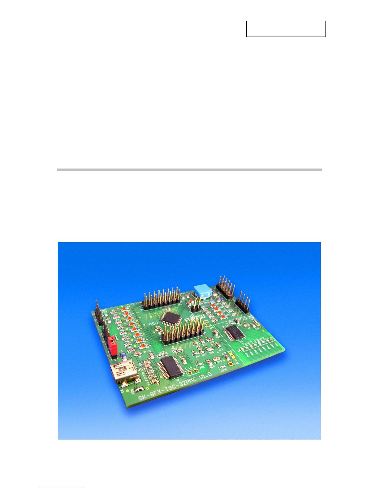
1.1 Abstract
The SK-8FX-TSC-32PMC is a multifunctional evaluation board for the Fujitsu 8FX Flash
microcontroller MB95330 Series, as well as for the FMA1125 Series Touch Sensor
Controller (TSC).
It can be used stand-alone for software development and testing or as a simple target board
to work with the emulator system.
The board allows the designer immediately to start software development and tuning of the
touch sensing parameters (sensitivity, timing, etc.) before his own final target system is
available.
Page 7

SK-8FX-TSC-32PMC User Guide
Chapter 1 Overview
© Fujitsu Semiconductor Europe GmbH - 7 - FMEMCU-UG-90003-10
1.2 Features
< MB95F334 Flash MCU and FMA1125DC-24S TSC mounted on PCB
< Power supply by USB
< Power-LED
< 10-pin Connector for MB2146-08-E BGMA Adapter (not included) for Flash programming
and debugging
< All MCU and TSC pins routed to connectors
< On-board connections can be opened by jumpers
< USB interface by USB-to-serial IC (virtual COM port), connectable to LIN-UART or
UART/SIO
< 8 User LEDs connected to MCU port
< 4 User LEDs connected to TSC GPIO pins with PWM capability
< Reset button, Reset LED
This board must only be used for test applications
in an evaluation laboratory environment.
Page 8

SK-8FX-TSC-32PMC User Guide
Chapter 1 Overview
FMEMCU-UG-90003-10 - 8 - © Fujitsu Semiconductor Europe GmbH
1.3 General Description
The SK-8FX-TSC-32PMC is provided with a F2MC-8FX Flash microcontroller MB95F334 in
a LQFP32-M30 (PMC) package, as well as a FMA1125DC-24S Touch Sensor Controller
(TSC) in a 24-pin SSOP package.
It can be used as a stand-alone evaluation board or together with the MB2146-08-E BGMA
adapter.
1.3.1 Serial communication
The MB95F334 MCU offers two different USART peripherals for serial communication. The
UART/SIO offers full duplex, double buffered communication in asynchronous (UART) or
clock-synchronous (SIO) modes. The LIN-UART additionally implements the LIN protocol.
The serial interface connected to the on-board serial-to-USB converter can be selected by
solder jumpers JP16 and JP17. By default, the UART/SIO is used.
1.3.2 I2C Bus
In addition to the standard serial interfaces, the MB95F334 MCU also features an on-chip
I2C controller with a clock rate of 400kHz. Pull-up resistors (2.7kOhms) are provided on the
PCB. The I2C bus is also used for communication with the on-board Touch Sensor
Controller (TSC).
1.3.3 MCU Pins
All pins of the microcontroller are connected to standard 100mil (2.54mm) pin headers and
are directly available to the user. On-board peripheral circuits such as the TSC, LEDs and
USB can be disconnected by solder jumpers to free the corresponding MCU pins.
1.3.4 Power Supply
The SK-8FX-TSC-32PMC is by default powered by the USB connection to a host PC or USB
power supply. Alternatively, a stabilized supply voltage can be connected to the pin headers
X4 (GND) and X5 (VCC). JP3 must be opened in this case to disconnect the voltage
supplied by the USB connector X3.
1.3.5 Touch Sensor Controller FMA1125
The SK-8FX-TSC-32PMC can also serve as evaluation platform for the FMA1125 Touch
Sensor Controller. For this purpose, it offers several features:
< FMA1125DC-24S Touch Sensor Controller (SSOP24 package) with 4-8 touch input
channels and 4-8 digital I/Os (4 pins can be configured as I/O or touch input)
< Connector for up to eight touch input channels, with ‘mini-slider’ on PCB
< Four LEDs connected to TSC GPIO pins
The FMA1125 is connected to the MB95F334 MCU using the I2C bus. By default, the TSC is
using I2C address 0x68; alternatively it can be set to 0x69 using JP9.
1.3.6 User LEDs
The evaluation board offers several user LEDs. Eight LEDs are connected to the MCU, and
four additional LEDs are connected to the TSC GPIO pins. The LEDs can be disconnected
using solder jumpers to free the corresponding pins.
.
Page 9
SK-8FX-TSC-32PMC User Guide
Chapter 1 Overview
© Fujitsu Semiconductor Europe GmbH - 9 - FMEMCU-UG-90003-10
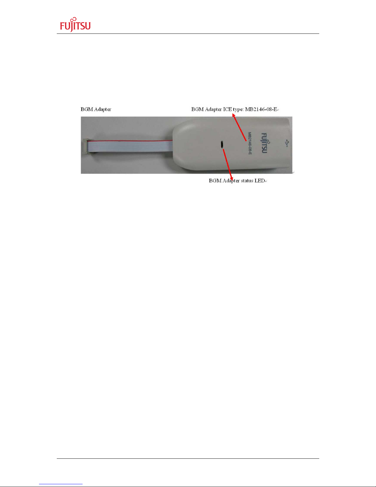
1.3.7 Debugging system (BGMA adapter)
The SK-8FX-TSC-32PMC can be used together with the MB2146-08-E BGMA adapter (not
included) for Flash programming of the MCU and for application debugging. For this, a 10pin connector (X2) is provided.
Figure 1: BGMA Adapter MB2146-08-E
Page 10

SK-8FX-TSC-32PMC User Guide
Chapter 2 Installation
FMEMCU-UG-90003-10 - 10 - © Fujitsu Semiconductor Europe GmbH
2 Installation
2.1 Connection/Power-On
Carefully remove the board from the shipping carton.
First, check if there are any damages before powering up the evaluation board.
For the power supply the usage of a host PC standard USB port or a USB power
supply is recommended. In case a separate power supply is used, it can be connected
to the pin headers X4 (GND) and X5 (VCC). JP3 must be opened in this case to
disconnect the voltage supplied by the USB connector X3.
As soon as the board is powered up, the green LED LD10 should light up. If the LED does
not light up, check the USB connection and jumper JP3.
Please refer to the corresponding user manuals and application notes for the BGMA adapter
on how to set up the debugging system.
2.2 Driver Installation
Many operating systems automatically recognize and enable the USB-to-serial converter IC
(FT232RL) used on the SK8-FX-TSC-32PMC. Standard VCP (Virtual COM port) drivers can
also be found on the CD included in the starter kit box, or directly on the FTDI homepage
under
http://www.ftdichip.com/Drivers/VCP.htm
When you connect the board to the PC, the PC will recognize the new hardware and display
messages prompting you to install the driver. Follow these steps to install the driver.
Page 11
SK-8FX-TSC-32PMC User Guide
Chapter 2 Installation
© Fujitsu Semiconductor Europe GmbH - 11 - FMEMCU-UG-90003-10
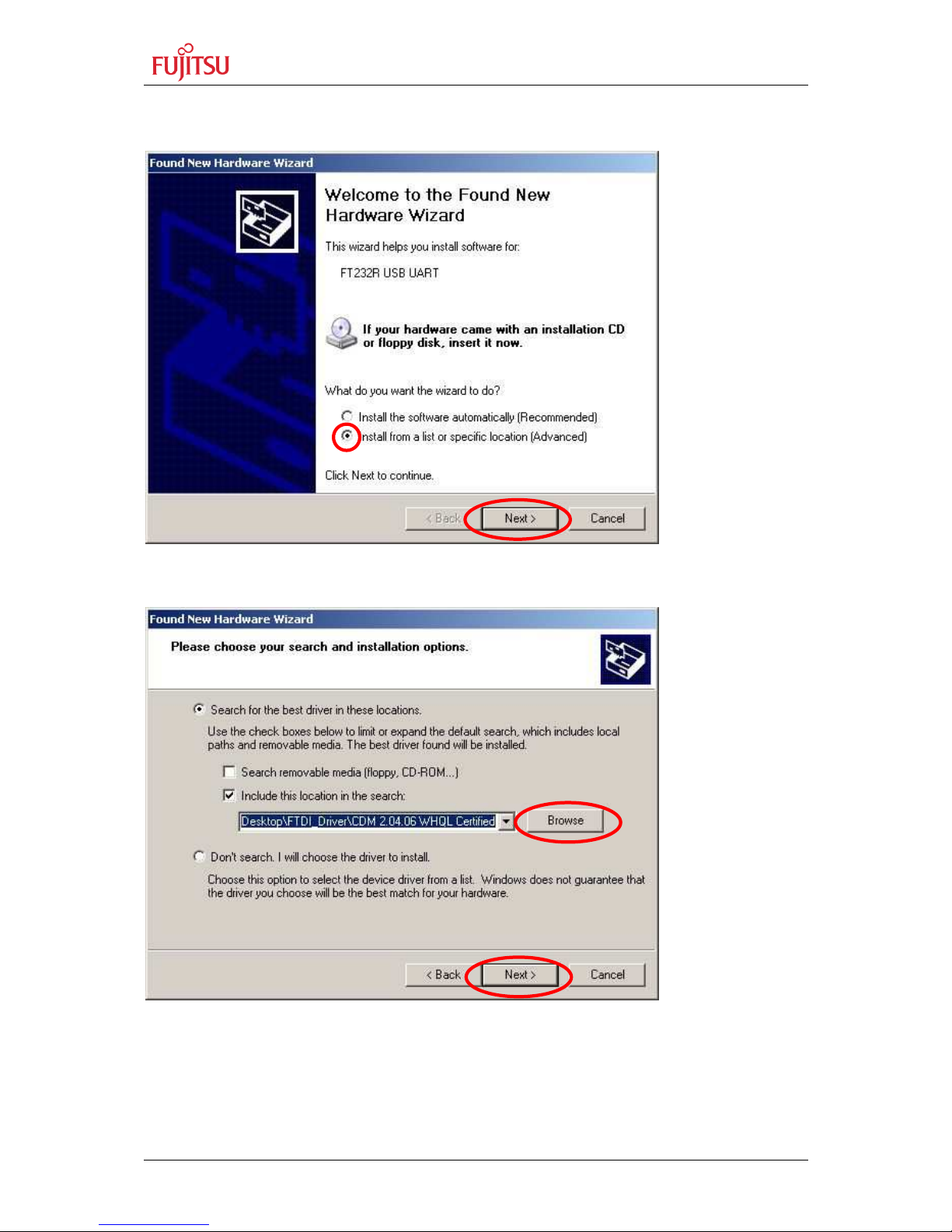
This procedure will explain how to install the driver software previously downloaded instead
of connecting to Windows Update.
Select "Install from a list or specific location (Advanced)", and click "Next".
Click "Browse" and specify the folder containing the driver, then click "Next".
Page 12

SK-8FX-TSC-32PMC User Guide
Chapter 2 Installation
FMEMCU-UG-90003-10 - 12 - © Fujitsu Semiconductor Europe GmbH
Wait for the "USB Serial Converter" installation to complete.
Click "Finish" to complete the installation of "USB Serial Converter".
Page 13

SK-8FX-TSC-32PMC User Guide
Chapter 2 Installation
© Fujitsu Semiconductor Europe GmbH - 13 - FMEMCU-UG-90003-10
Next, install the "USB Serial Port".
Select "Install from a list or specific location (Advanced)", and click "Next".
Click "Browse" and specify the folder "CDM 2.04.06 WHQL Certified" downloaded earlier,
then click "Next".
Page 14

SK-8FX-TSC-32PMC User Guide
Chapter 2 Installation
FMEMCU-UG-90003-10 - 14 - © Fujitsu Semiconductor Europe GmbH
Wait for the "USB Serial Port" installation to complete.
Click "Finish" to complete the installation of "USB Serial Port".
This completes the installation of the USB driver. Now that
the VCP Driver was installed,
a new serial interface will be available in the system.
Page 15

SK-8FX-TSC-32PMC User Guide
Chapter 2 Installation
© Fujitsu Semiconductor Europe GmbH - 15 - FMEMCU-UG-90003-10
2.3 Default Jumper settings
The following table lists all jumpers including its default setting on the board.
Jumper Description / Function Type
Default
Setting
JP1 User LED LD2-LD9 Solder JP 2 pin Closed
JP2 User RESET Jumper 2 pin Closed
JP3 USB Power Jumper 2 pin Closed
JP4 I2C SCL Solder JP 2 pin Closed
JP5 I2C SDA Solder JP 2 pin Closed
JP6 P05 – TSC Reset Solder JP 2 pin Closed
JP7 INT00 – TSC TINT Solder JP 2 pin
Open
JP8 INT01 – TSC GINT Solder JP 2 pin
Open
JP9 TSC I2C ID select (0x68/0x69) Solder JP 3 pin
1-2
JP10 TSC internal LDO Solder JP 2 pin Closed
JP11 TSC User LED LD11 Solder JP 2 pin Closed
JP12 TSC User LED LD12 Solder JP 2 pin Closed
JP13 TSC User LED LD13 Solder JP 2 pin Closed
JP14 TSC User LED LD14 Solder JP 2 pin Closed
JP15 TSC TCLK input Solder JP 2 pin Closed
JP16 Serial Data reception port (UI0/SIN) Solder JP 3 pin
1-2
JP17 Serial Data transmission port (UO0/SOT) Solder JP 3 pin
1-2
Table 2-1: Jumper Settings
Page 16

SK-8FX-TSC-32PMC User Guide
Chapter 3 Jumpers and Switches
FMEMCU-UG-90003-10 - 16 - © Fujitsu Semiconductor Europe GmbH
3 Jumpers and Switches
This chapter describes all jumpers and switches that can be modified on the evaluation
board. The default setting is shown with a grey shaded area.
3.1 Power Supply (JP3)
The SK-8FX-TSC-32PMC is by default powered by the USB connection to a host PC or USB
power supply. Alternatively, a stabilized supply voltage can be connected to the pin headers
X4 (GND) and X5 (VCC). JP3 must be opened in this case to disconnect the voltage
supplied by the USB connector X3.
JP3: Connects VCC to USB power supply
Jumper Setting Description
JP3
(USBPWR)
Closed Board powered by USB (X3)
Open Board not powered by USB
Table 3-1: Power Supply Configuration
3.2 User LEDs (JP1)
Eight LEDs are supplied for user applications. In order to disable the LEDs e.g. to use the
related microcontroller port (Port P62-P67, P06-P07) for other connections, JP1 (solder
jumper) can be opened.
JP1: Enables User LEDs LD2-LD9 to VCC
Jumper Setting Description
JP1
(LED_VCC)
Closed LEDs enabled (anodes connected to VCC)
Open LEDs disabled
Table 3-2: Use LED enable / disable
The User LEDs are connected to the MCU pins according to the table below:
LED Number
MCU Pin MCU Port
LD2 10 P62
LD3 9 P63
LD4 8 P64
LD5 7 P65
LD6 6 P66
LD7 5 P67
LD8 19 P06
LD9 20 P07
Table 3-3: User LED connections
Page 17

SK-8FX-TSC-32PMC User Guide
Chapter 3 Jumpers and Switches
© Fujitsu Semiconductor Europe GmbH - 17 - FMEMCU-UG-90003-10
3.3 User Reset (JP2)
In case the MB2146-08-E BGMA adapter is used, the on-board User Reset button (SW1)
should be disconnected from the MCU reset input by opening JP2 to enable reset control by
the BGMA adapter during debugging.
Please check the related documentation of the BGMA adapter for details.
JP2: User Reset Switch enable
Jumper Setting Description
JP2
(User Reset)
Closed SW1 controls MCU reset pin
Open SW1 not connected to MCU reset pin
Table 3-4: Power Supply Configuration
3.4 UART select (JP: 16, JP17)
The MB95330 Series MCU offers two different serial interfaces, LIN-UART and UART/SIO.
JP16 and JP17 can be used to select which interface is connected to the on-board serial-toUSB converter.
JP16 Serial Data reception port (UI0/SIN)
JP17 Serial Data transmission port (UO0/SOT)
Jumper Setting Description
JP16
(RX)
1-2 AVcc is connected to Vcc
2-3 AVcc is disconnected from Vcc
JP17
(TX)
1-2 AVRH is connected to AVcc
2-3 AVRH defined by resistor network*1
Table 3-5: UART select
Page 18

SK-8FX-TSC-32PMC User Guide
Chapter 3 Jumpers and Switches
FMEMCU-UG-90003-10 - 18 - © Fujitsu Semiconductor Europe GmbH
3.5 MCU-TSC interface (JP: 4, 5, 6, 7, 8)
Five jumpers can be used to connect or disconnect the TSC and MCU.
.
Jumper Setting Description
JP4
(I2C SCL)
Closed TSC and Pullup connected to MCU SCL (Pin11)
Open TSC and Pullup not connected to MCU SCL (Pin11)
JP5
(I2C SDA)
Closed TSC and Pullup connected to MCU SDA (Pin11)
Open TSC and Pullup not connected to MCU SDA (Pin11)
JP6
(TSC Reset)
Closed TSC Reset input connected to MCU P05 (Pin18)
Open TSC Reset input not connected to MCU P05 (Pin18)
JP7
(TSC TINT)
Closed TSC Touch Interrupt connected to MCU INT00 (Pin13)
Open TSC Touch Interrupt not connected to MCU
JP8
(TSC GINT)
Closed TSC General Interrupt connected to MCU INT01 (Pin14)
Open TSC General Interrupt not connected to MCU
Table 3-6: TSC-MCU interface
By default, the TSC is connected to the MCU by I2C and RESET lines, while the interrupt
lines are not connected.
3.6 TSC configuration (JP: 9, 10, 15, C14)
JP9 TSC I2C ID select (0x68 / 0x69)
JP10 Internal LDO
JP15 TCLK (external Clock) input
C14 TSC tuning capacitor (not mounted)
Jumper Setting Description
JP9
(TSC ID)
1-2 TSC I2C ID set to 0x68
2-3 TSC I2C ID set to 0x69
JP10
(LDO)
Closed TSC logic connected to internal LDO´(2.5V)
Open TSC logic not connected to internal LDO
JP15
(TCLK)
Closed TCLK input connected to GND (internal clock used)
Open TCLK can be used as external test clock input
Table 3-7: TSC configuration
Page 19

SK-8FX-TSC-32PMC User Guide
Chapter 3 Jumpers and Switches
© Fujitsu Semiconductor Europe GmbH - 19 - FMEMCU-UG-90003-10
By default, the TSC ID is set to 0x68, and the TSC is operating from its internal 2.5V
Regulator (LDO) and internal oscillator.
The (optional) tuning capacitor C14 is not mounted by default. In case of touch applications
with very high offset capacitance, a small (some few pF) can be mounted here to
compensate the offset capacitance of the touch input pins. Please refer to the ‘basic tuning
process’ chapter later in this document for details about the tuning capacitor.
Please refer to the TSC documentation (on CD) for details about TSC operation and
configuration.
3.7 TSC User LEDs (JP: 11, 12, 13, 14)
Four LEDs are connected to the TSC’s GPIO pins. The TSC can control the LEDs by
switching or PWM dimming.
Jumper Setting Description
JP11
(LD11)
Closed LD11 is connected to TSC GPIO0 (TSC Pin 22)
Open LD11 is not connected
JP12
(LD12)
Closed LD12 is connected to TSC GPIO1 (TSC Pin 1)
Open LD12 is not connected
JP13
(LD13)
Closed LD13 is connected to TSC GPIO2 (TSC Pin 4)
Open LD13 is not connected
JP14
(LD14)
Closed LD14 is connected to TSC GPIO3 (TSC Pin 8)
Open LD14 is not connected
Table 3-8: TSC User LEDs
Page 20

SK-8FX-TSC-32PMC User Guide
Chapter 4 Connectors
FMEMCU-UG-90003-10 - 20 - © Fujitsu Semiconductor Europe GmbH
4 Connectors
4.1 USB connector (X3)
A standard USB B-mini type connector can be used for power supply and for communication
with a host PC via the on-board serial-to-usb converter. A USB cable is included.
4.2 MCU pin header connectors (X11, X12)
All pins of the microcontroller are directly connected to pin headers. The pin marking next to
the connector reflects the pin number of the microcontroller.
4.3 BGMA connector (X2)
A 10-pin header is provided to connect an MB2146-08-E BGMA adapter (not included) for
Flash memory programming and debugging.
Please be sure of correct orientation of the BGMA adapter on X2 before powering up the
system. Pin 1 (marked on the ribbon cable and connector of the BGMA adapter) must be
located at the outer edge of the PCB.
Jumper JP2 must be opened when using the BGMA adapter, otherwise an error message
will be displayed.
When powering up, please follow the order given below:
1. Connect BGMA adapter to the SK-8FX-TSC-32PMC.
2. Connect BGMA adapter to host USB port (LED on BGMA adapter should be green)
3. Power up the SK-8FX-TSC-32PMC (LED on BGMA adapter should turn orange)
Pin Number Pin Signal Description
1 UVCC VCC of target system, used to detect target power status
2 GND Target system GND
3 RSTIN Reset input (from BGMA to MCU)
4 RSTOUT Reset output (from target system to BGMA)
5 Reserved
6 Reserved
7 Reserved
8 DBG Single-wire Debug Pin
9 Reserved
10 Reserved
Table 4-1: BGMA Connector Signals
For details about the BGMA usage, please refer to the application notes included (on CD).
Page 21

SK-8FX-TSC-32PMC User Guide
Chapter 4 Connectors
© Fujitsu Semiconductor Europe GmbH - 21 - FMEMCU-UG-90003-10
4.4 GND Connector (X4)
System ground.
4.5 VCC Connector (X5)
This connector can be used to monitor the boards supply voltage or connect an external
power supply (usually 3.3V - 5V, please check related data sheets of MCU and TSC for valid
supply voltage range, depending on the application conditions).
4.6 TSC GPIO Connector (X6)
This connector holds the signals of the TSC GPIO pins 0-3. A LED (which can be
disconnected by a jumper) is connected to each of these signals as well.
Pin Number Pin Signal Description
1 GPIO0 TSC GPIO pin 0
2 GPIO1 TSC GPIO pin 1
3 GPIO2 TSC GPIO pin 2
4 GPIO3 TSC GPIO pin 3
Table 4-2: TSC GPIO Connector Signals
4.7 TSC Touch Input Connector (X7)
This connector can be used to attach external touch electrodes to the TSC inputs.
The touch inputs can be configured as GPIO pins; please refer to the documentation (on
CD) for details.
Pin Number Pin Signal Description
1 PA0 Touch input 0 (or GPIO)
2 PA1 Touch input 1 (or GPIO)
3 PA2 Touch input 2 (or GPIO)
4 PA3 Touch input 3 (or GPIO)
5 PA4 Touch input 4 (or GPIO)
6 PA5 Touch input 5 (or GPIO)
7 PA6 Touch input 6 (or GPIO)
8 PA7 Touch input 7 (or GPIO)
Table 4-3: TSC Touch Input Connector Signals
Page 22

SK-8FX-TSC-32PMC User Guide
Chapter 5 Basic TSC Tuning Process
FMEMCU-UG-90003-10 - 22 - © Fujitsu Semiconductor Europe GmbH
5 Basic TSC Tuning Process
Following some basic rules during the tuning process of an FMA1125 touch application can
help to get the application running quickly. An example program is pre-programmed on the
SK-8FX-TSC-32PMC, which enables easy parameter tuning using a sort of command-line
interface to a host PC running a standard terminal program (8N1, 115200 baud).
Type ‘help’ followed by <ENTER> for a list of available commands.
Note:
Please keep in mind that the tuning firmware shows the Impedance and Reference
Impedance values as ‘127-Register Value’ in order to have a more intuitive behaviour
(a touched key then gives a higher impedance value than an untouched one).
5.1 Reference Delay
The first Parameter to adjust is the Reference Delay. This parameter is used to globally
compensate parasitic capacitance present on all tracks. It can be set in the example
Firmware using the ‘srd’ command, followed by a blank the desired value. The influence on
the Impedance and Reference Impedance values can be seen below:
The average value of the Impedance and Reference registers should be around the middle
of the scale, and a reserve of about 20-30 counts should be kept to zero and full-scale in
order to enable correct AIC (Automatic Impedance Calibration) operation.
In case the difference between biggest and smallest values is too big (some values close to
zero, others close to max.), tuning capacitors can be used to roughly match the
capacitances. Every count of the Impedance Register corresponds to a value of 0.078pF
(default settings of FMA1125) on the input pin, so that e.g. attaching a 4.7pF capacitor
between GND and the input pin with the smallest value will increase the bar by about 60
counts.
In case some values are close to the maximum even though Reference Delay is already set
to the maximum value (127), an additional capacitor can be connected to the PAREF pin.
RefDelay = max.
(Too high for this layout,
inputs are too small)
RefDelay = 50
(ideal for this layout)
RefDelay = 0
(Too low for this layout,
inputs are saturated)
Page 23

SK-8FX-TSC-32PMC User Guide
Chapter 5 Basic TSC Tuning Process
© Fujitsu Semiconductor Europe GmbH - 23 - FMEMCU-UG-90003-10
This capacitor is called ‘Tuning Capacitor’ (C14 on the SK-8FX-TSC-32PMC). Also here,
one step of Reference Delay register corresponds to 0.078pF when using the default
settings, so that attaching a 4.7pF capacitor to the PAREF pin will decrement all impedance
values by about 60 counts.
The maximum value for the reference tuning capacitor can be found in the device data
sheet.
The resolution of the above registers can be set using the R_SEL options. Please refer to
the register description in the documentation (on CD) for details.
5.2 Alpha
The Alpha parameter is used to control the sensitivity of every channel individually. In idle
state (no touch), the AIC will set the Reference Impedance value for every channel to be
(Impedance + Alpha). This means, the signal introduced by a finger in order to be
recognized as a touch has to increase the Impedance value by at least ‘Alpha’ counts. In
other words, increasing the Alpha for a channel makes it less sensitive, a smaller Alpha will
make the channel more sensitive.
The Alpha values can be set using the following commands:
• sa channel value – Set a single channel‘s alpha to value
• sax value – Set alpha of all channels to value
• a-value – decrement all alpha by value
• a+value – increment all alpha by value
Typical values for Alpha are in the range of 4…30, depending on electrode size, front cover
thickness, etc. For proximity applications, also smaller values of Alpha can be used, but care
must be taken that AIC is still operating correctly. Also, the Filter Period and Filter Threshold
should be used to filter out short pulses and increase stability.
5.3 Filter Period, Filter Threshold
The Filter Period and Filter Threshold registers can be used to apply a kind of low-pass filter
to the touch output. A touch will only be signalled, when at least ‘Filter Threshold’ samples of
‘Filter Period’ samples are active. This can be used to increase stability, ot to filter out short
touches. It should usually be kept active, e.g. with Period = 5 and Threshold = 4. The filter
function has to be enabled by setting the FILTER_EN bit in the Feature Select register
(0x13).
5.4 Impedance, Calibrated Impedance
In addition to reading out the digital APIS on/off information for every touch channel, the TSC
offers access to the sensor reference and input impedance values. This can be used e.g. for
slider, scroll wheel or touch pad applications.
The Impedance register contains the value of the measured input impedance, whereas the
Reference Impedance register contains the corresponding reference value for each channel.
The difference between both in idle state is equal to the corresponding Alpha value, which is
handled by the AIC by setting the Reference Impedance value accordingly.
This means that the Alpha parameter and also AIC operation (calibration) do not affect the
value in the Impedance register. The Impedance register always reflects the input
Page 24

SK-8FX-TSC-32PMC User Guide
Chapter 5 Basic TSC Tuning Process
FMEMCU-UG-90003-10 - 24 - © Fujitsu Semiconductor Europe GmbH
impedance, only shifted by the Reference Delay Parameter, which is usually constant during
the application runtime and set only during initial tuning. Therefore, it can be used to monitor
the raw sensor data of every channel individually for advanced sensing applications. The
Impedance and Reference Impedance register values are updated once per AIC interval.
For Slider and similar applications, the (positive) difference between Impedance and
Reference Impedance can be used as strength value for each channel, and using an
interpolation algorithm, high-resolution poison information can be calculated. Please refer to
the SK-TSC-1127-SB example software for implementation details (available on the Fujitsu
Web site mentioned in the appendix of this document).
Page 25

SK-8FX-TSC-32PMC User Guide
Chapter 6 Appendix
© Fujitsu Semiconductor Europe GmbH - 25 - FMEMCU-UG-90003-10
6 Appendix
6.1 Related Products
< MB2146-420-01-E Low-cost evaluation board for MB95F260 Series MCU
Includes an MB2146-08-E BGMA adapter
< MB2146-08-E BGMA adapter for Flash programming and debugging
< SK-TSC-1125S Starter Kit / Test Board for FMA1125 TSC
< SK-TSC-1127-SB Starter Kit for FMA1127 TSC
< SK-TSC-1127-TB Test Board for FMA1127 TSC
Page 26

SK-8FX-TSC-32PMC User Guide
Chapter 7 Information in the WWW
FMEMCU-UG-90003-10 - 26 - © Fujitsu Semiconductor Europe GmbH
7 Information in the WWW
Information about FUJITSU SEMICONDUCTOR Products
can be found on the following Internet pages:
Microcontrollers (8-, 16- and 32-bit), Graphics Controllers
Datasheets and Hardware Manuals, Support Tools (Hard- and Software)
http://mcu.emea.fujitsu.com/
Touch Sensor Controllers
http://www.fujitsu.com/emea/services/microelectronics/tsc/
Power Management Products
http://www.fujitsu.com/emea/services/microelectronics/powerman/
Media Products: SAW filters, acoustic resonators and VCOs
http://www.fujitsu.com/emea/services/microelectronics/saw/
For more information about FUJITSU SEMICONDUCTOR
http://www.fujitsu.com/emea/services/microelectronics/
Page 27

SK-8FX-TSC-32PMC User Guide
Chapter 8 China-RoHS regulation
© Fujitsu Semiconductor Europe GmbH - 27 - FMEMCU-UG-90003-10
8 China-RoHS regulation
This board is compliant with China RoHS
Page 28
SK-8FX-TSC-32PMC User Guide
Chapter 9 Recycling
FMEMCU-UG-90003-10 - 28 - © Fujitsu Semiconductor Europe GmbH
9 Recycling
Gültig für EU-Länder:
Gemäß der Europäischen WEEE-Richtlinie und deren Umsetzung in landesspezifische
Gesetze nehmen wir dieses Gerät wieder zurück.
Zur Entsorgung schicken Sie das Gerät bitte an die folgende Adresse:
Fujitsu Semiconductor Europe GmbH
Warehouse/Disposal
Monzastraße 4a
63225 Langen
Valid for European Union Countries:
According to the European WEEE-Directive and its implementation into national laws we
take this device back.
For disposal please send the device to the following address:
Fujitsu Semiconductor Europe GmbH
Warehouse/Disposal
Monzastraße 4a
63225 Langen
 Loading...