

Page 1
FUJITSU SEMICONDUCTOR
PRODUCT GUIDE
2003.5
Product Guide
[Microcomputer]
PG00-00031-2E,
Page 2
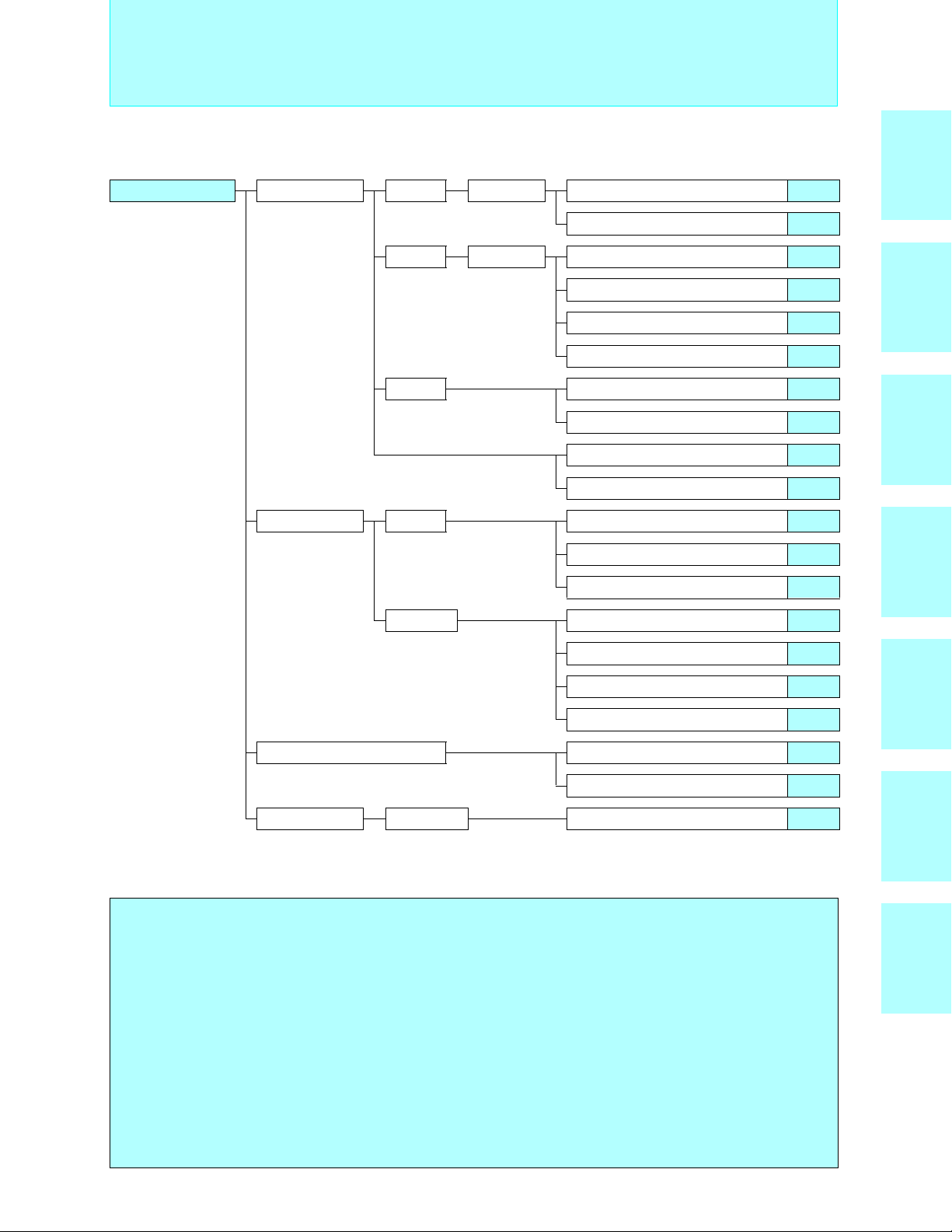
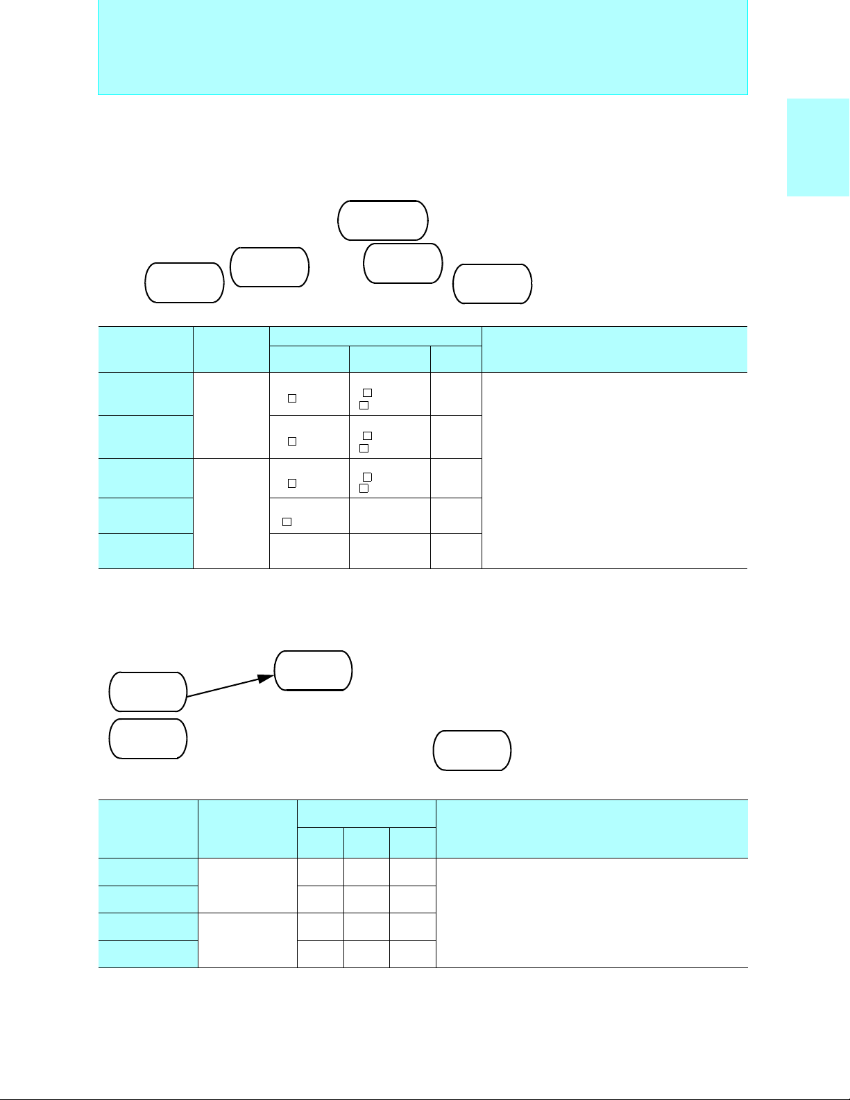
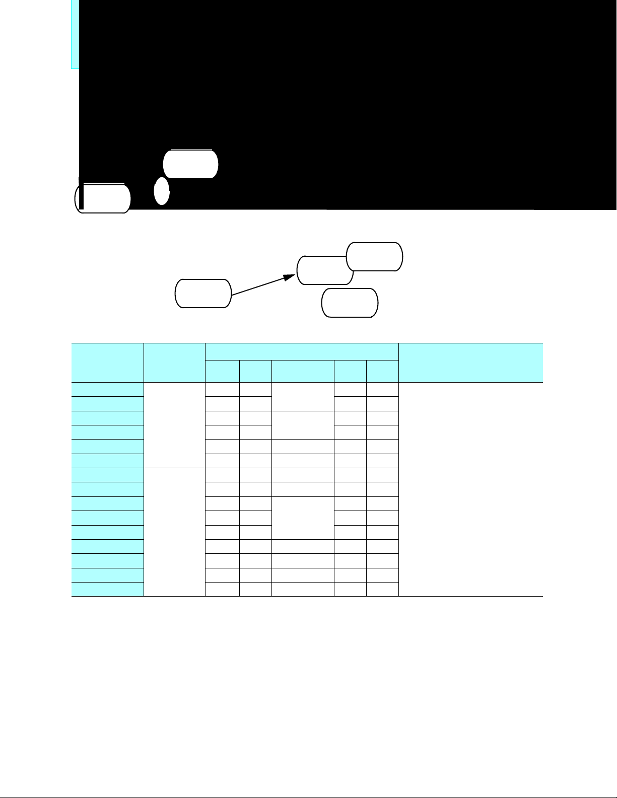
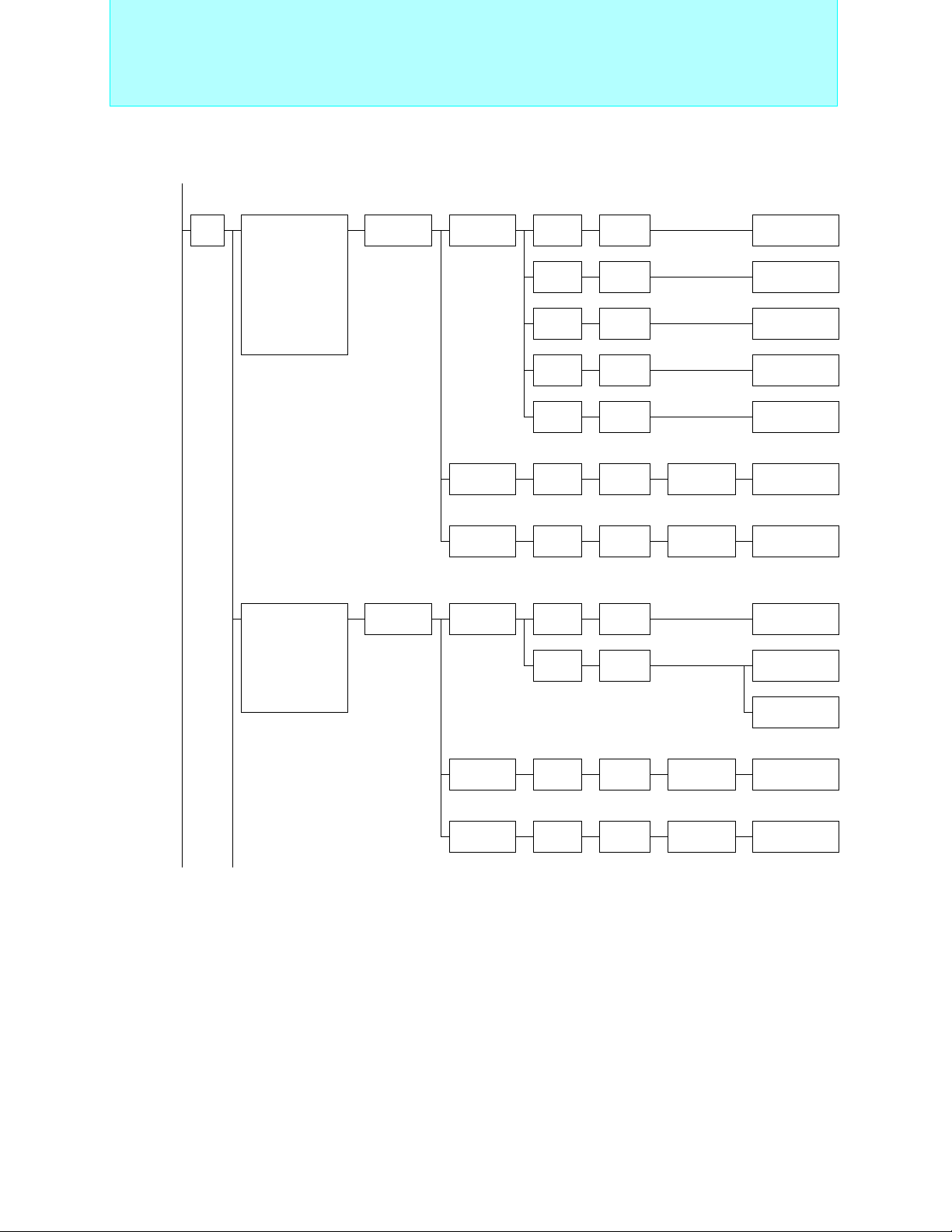
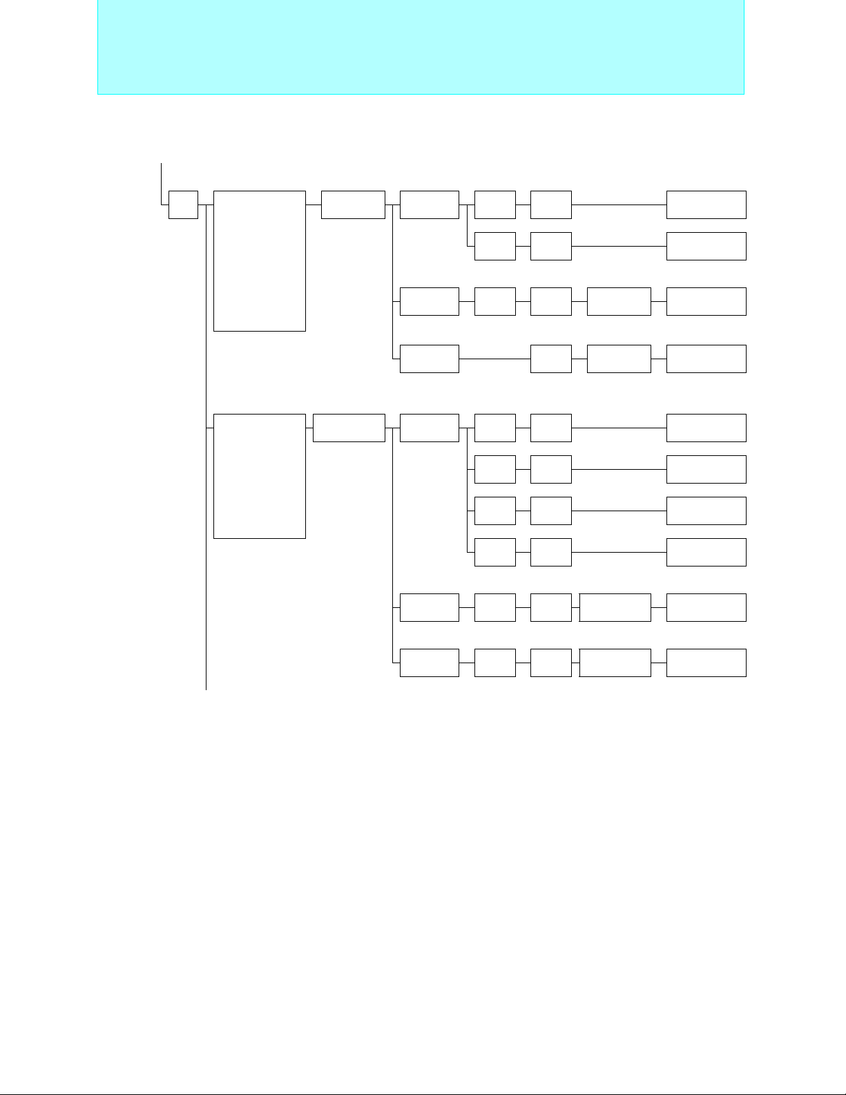
Product Line-up
Microcomputers Microcontrollers 8-bit Proprietary
16-bit Proprietary
32-bit FR Family
Microprocessor FR-V FR-V Family
SPARClite Embedded MPU
2
MC-8L Family
F
Support tools
2
MC-16L Family
F
2
F
MC-16LX Family
2
F
MC-16F Family
Support tools
Support tools
Microcontroller product list
Support Hardware
Support tools
Middleware
Page no.
4
60
80
92
126
138
172
182
244
274
218
222
227
230
MC-8LFamily
2
F
Family
MC-16L/LX/F
2
F
FR FamilySPARCliteDigital signal
Compound peripherals for SPARClite
Support tools
Microprocessor product (SPARClite) list
Digital signal processor Hi-Perion Family
Support tools
Resonator
Piezoelectric
resonator
FAR Family 242
Microcomputer Migration Path
TRADEMARKS:
• SPARC is a registered trademark of SPARC International, Inc. in the United States.
SPARC is based on technology developed by Sun Microsystems, Inc.
SPARClite is a trademark of SPARC International, Inc. in the United States.
Fujitsu Microelectronics, Inc. has been granted permission to use the trademark.
• MS-DOS and MS-Windows are trademarks of Microsoft Corporation of the USA.
• PC/AT and PC-DOS are trademarks of International Business Machines Corporation of USA.
• Sun OS/Solaris and Sun 4 are trademarks of Sun Microsystems Corporation of USA.
• HP-UX is a trademark of Hewlett-Packard.
• IE Bus is trademark of NEC Corporation.
2
C LICENSE:
THE I
Purchase of FUJITU Ltd. I2C components conveys a license under the Philips I2C Patent Right to use these components in an
2
I
C system, provided that the system conforms to the I2C Standard Specification as defined by Philips.
230
232
311
236
238
processor
FAR Family FR-V Family
1
Page 3

2
Page 4

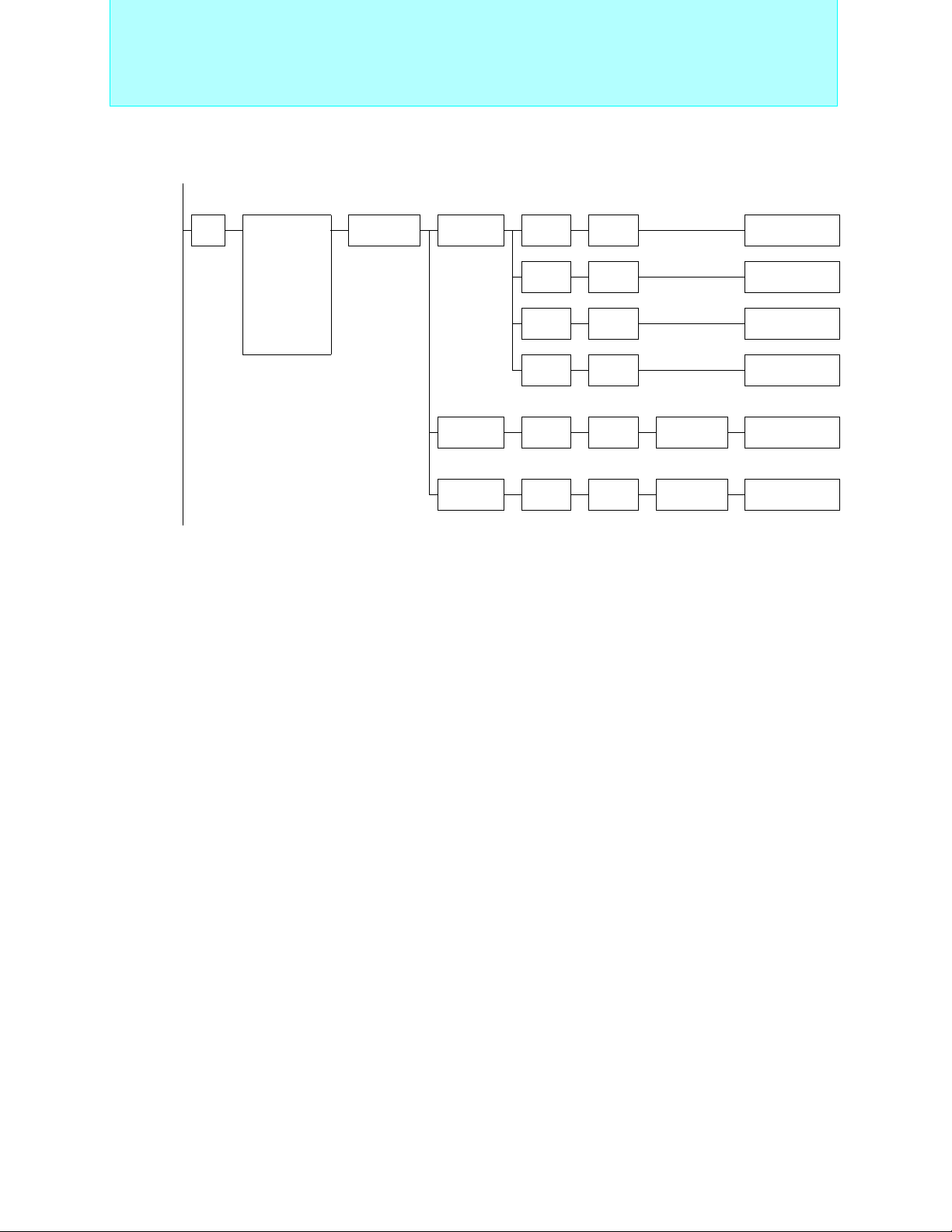
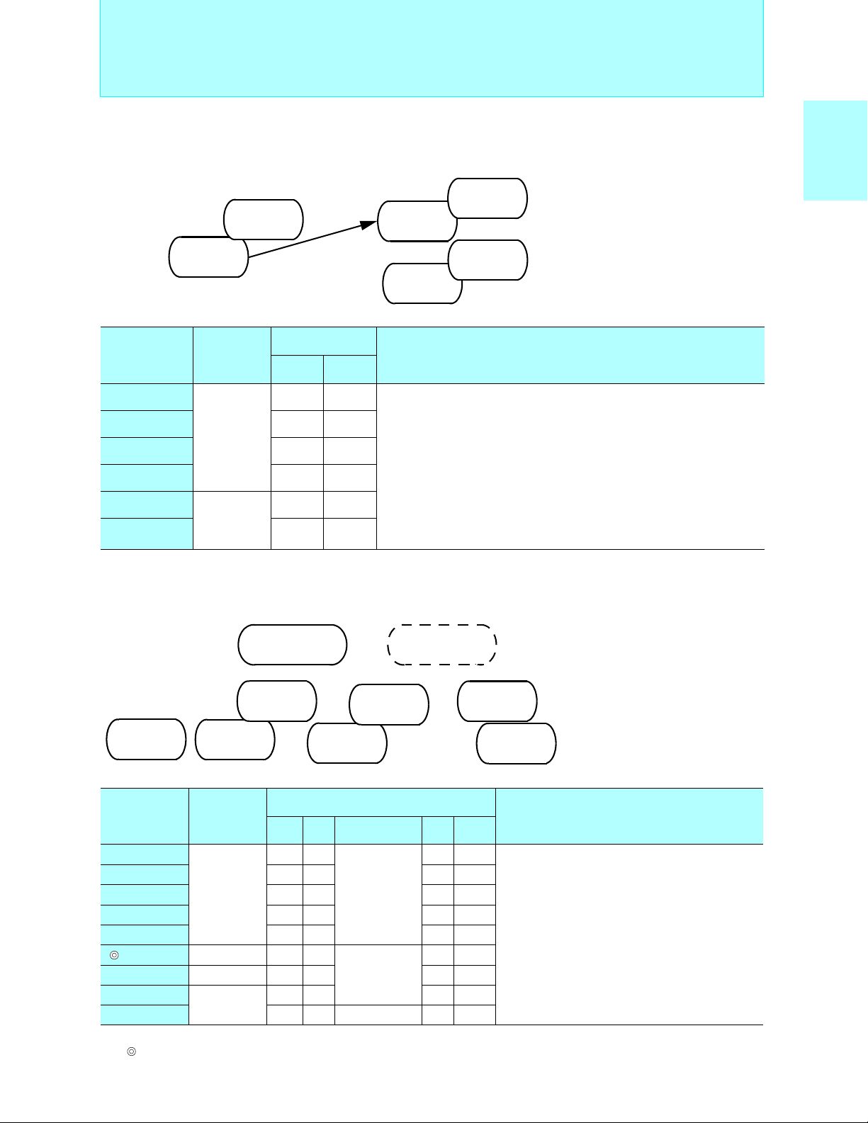
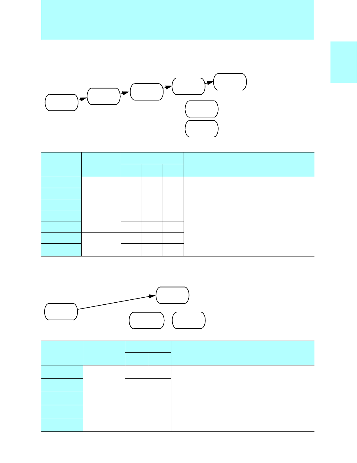
Microcomputer Range
■ 32-bit Microprocessor
• FR-V Family
Fujitsu’s original processor whose media processing performance is enhanced by adding
VLIW architecture and media instruction, etc.
• SPARClite
A 32-bit RISC microprocessor aimed at embedded applications and based on the SPARC
architecture
■ 32-bit Microcontrollers
• FR (FR30 Series, FR50 Series, FR60 Series)
A proprietary Fujitsu product developed for embedded applications
A microcontroller with a 32-bit RISC architecture
■ 16-bit Microcontrollers
•F2MC-16L (MB90600 series)
Features: Low voltage (+2.7V to +5.5V), low price
Applications: For applications including information consumer products,
communications, and OA
2
MC-16LX (MB90500 series)
•F
Features: Supports high-performance, low-power consumption, large memory space
Applications: For applications including consumer information products and
telecommunications instruments
2
MC-16F (MB90200 series)
•F
Features: Provides high-speed signed instructions and C language real time
operating system instructions
Applications: For high-speed real time control
MC-8LFamily
2
F
■ 8-bit Microcontrollers
•F2MC-8L (MB89100 series, MB89500 series, MB89600 series, MB89800 series, and
MB89900 series)
Features: Low voltage (+2.2V to +6.0V), low-power consumption
Applications: 8-bit microcontrollers for consumer markets
3
Page 5
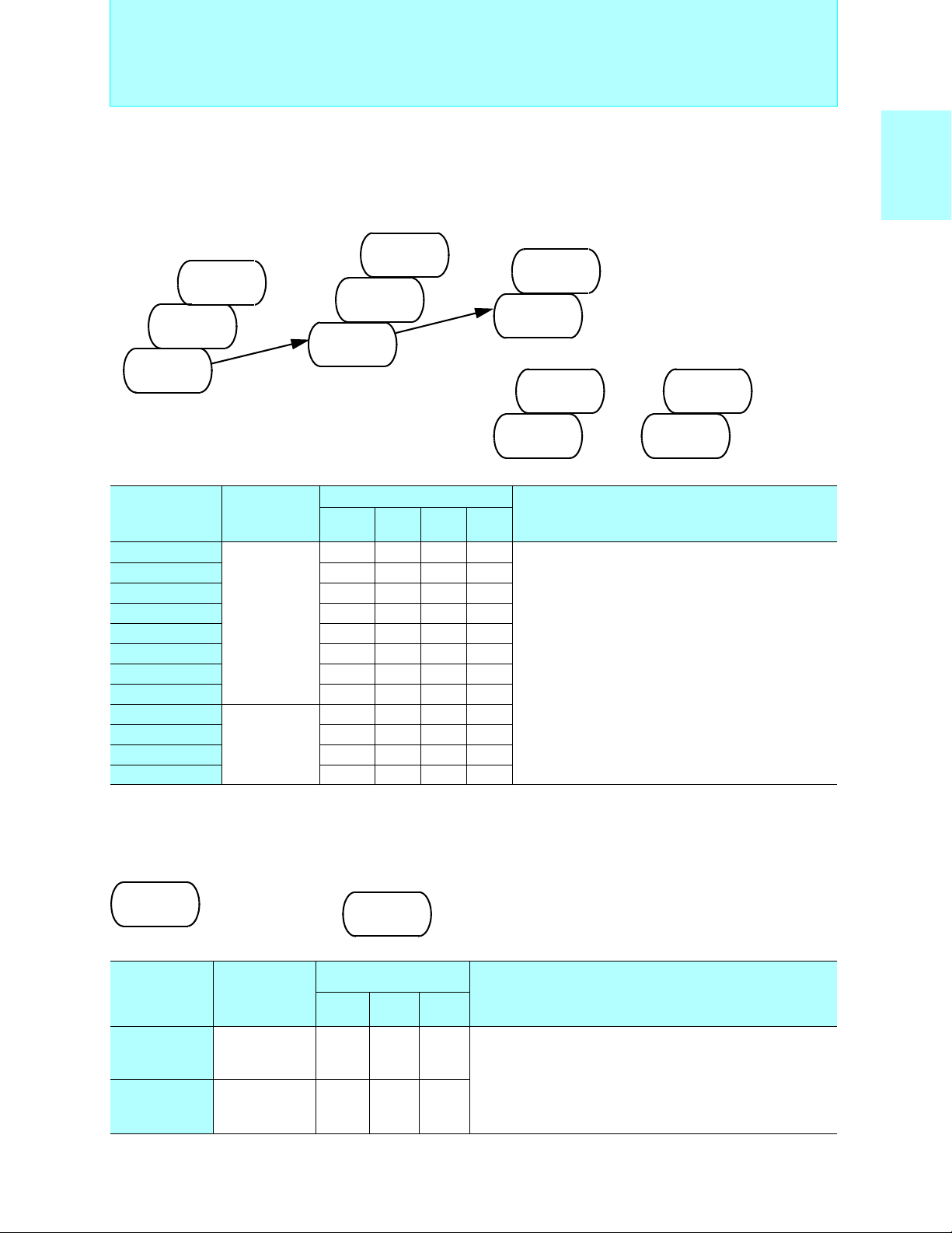
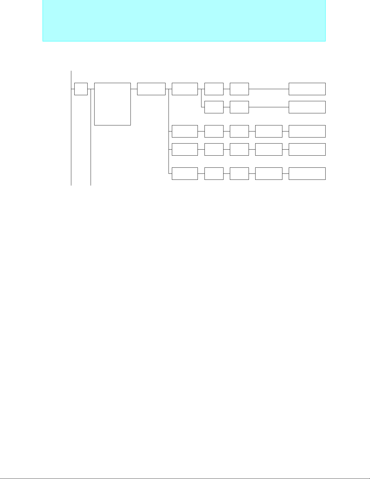
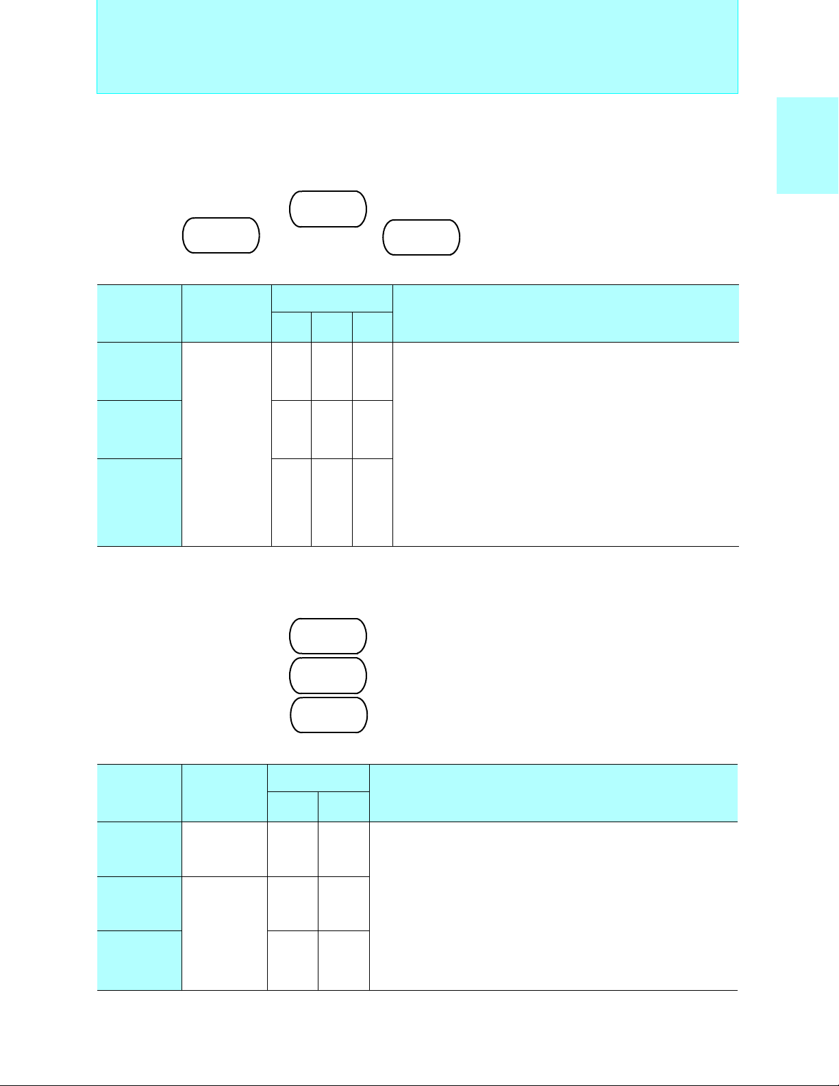
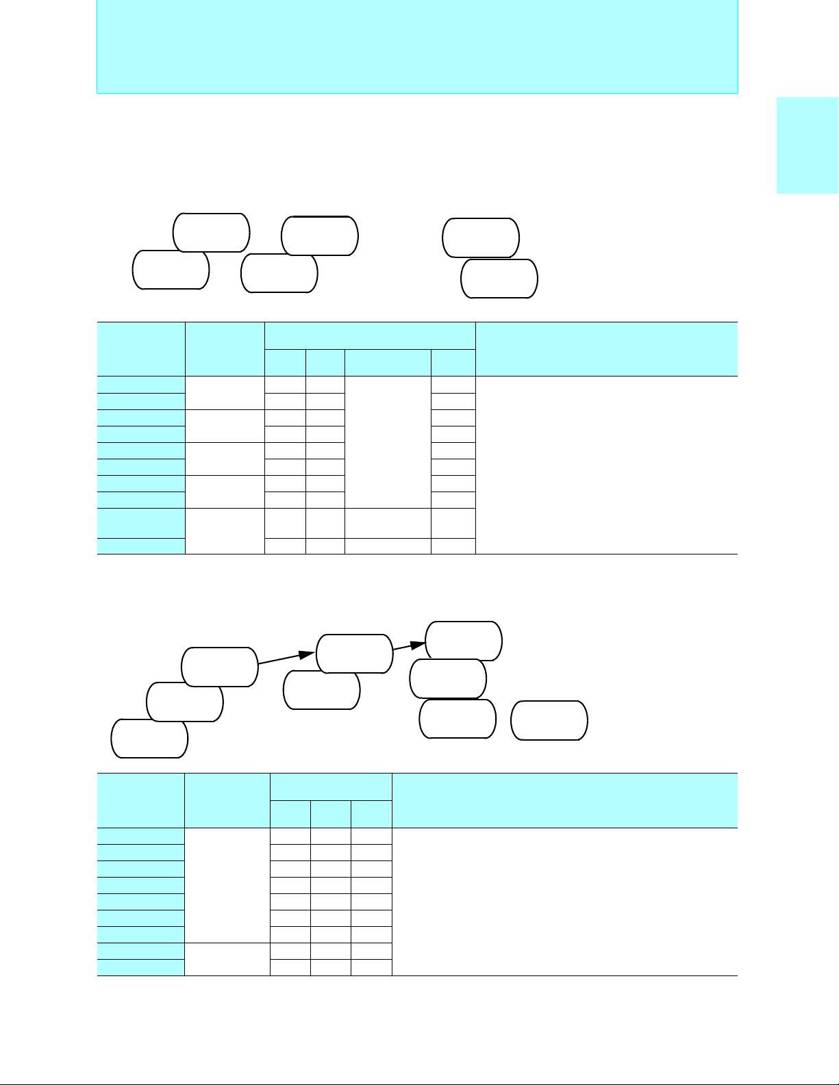
8-bit Proprietary F2MC-8L Family Features
2
MC-8L Family Features
■ F
• Minimum execution time: 0.32µs/12.5MHz, 0.4 µs/10MHz, 0.95 µs/4.2 MHz
• Operating voltage: +2.2 V to +6.0 V, operating frequency: 1 MHz to 10 MHz
• Software-switchable instruction cycle (4 speeds) provides low voltage, low-power comsumption operation (clock
gear function)
• Backup voltage in stop mode (voltage required to maintain RAM data): Min. +1.5 V
• Bitwise selectable pull-up resistors for each I/O port
• One-time PROM products support (by programming data) the same option settings as mask ROM products (the
option settings are mask options for some products).
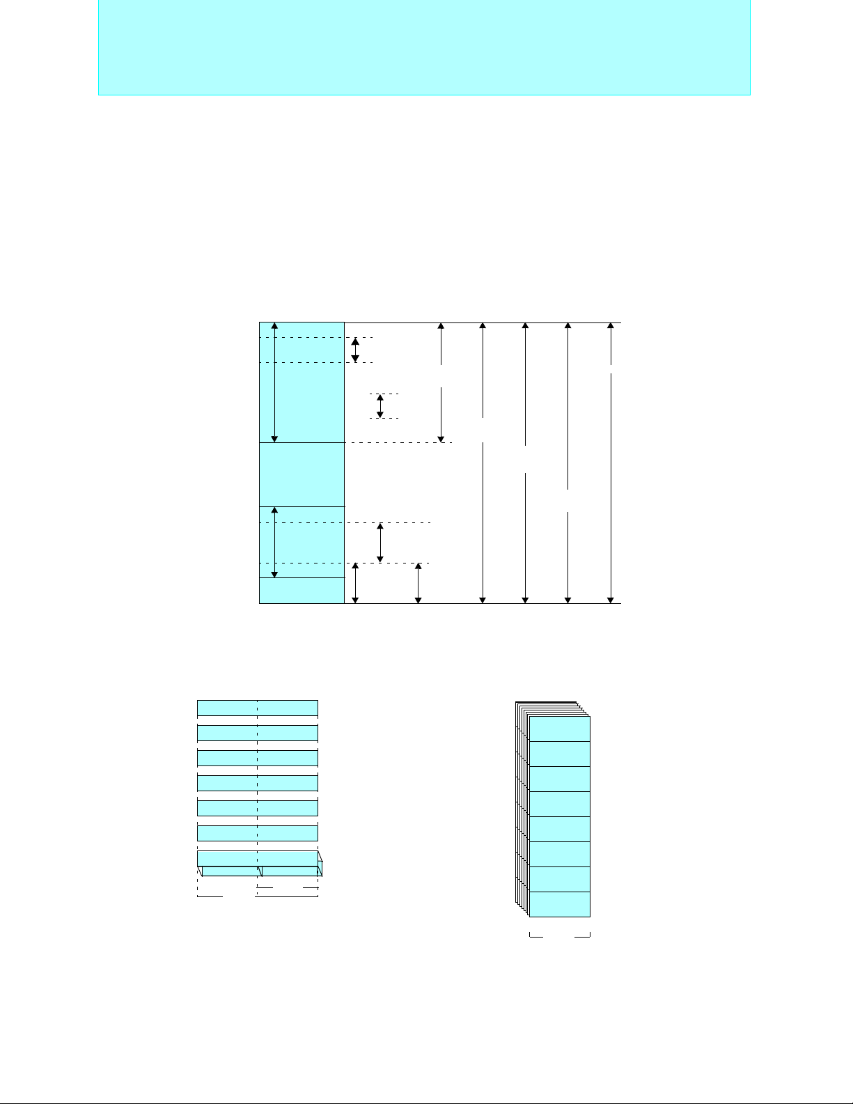
• Memory space: Max. 64 Kbytes
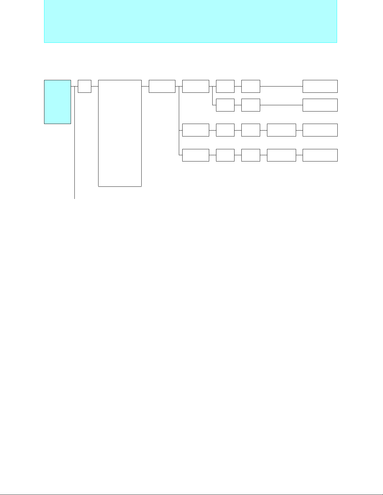
Memory space
FFFFH
FFD0H
FFC0H
Program
area
External
area
0200H
Data area
0100H
I/O area
0000H
• Memory mapped I/O
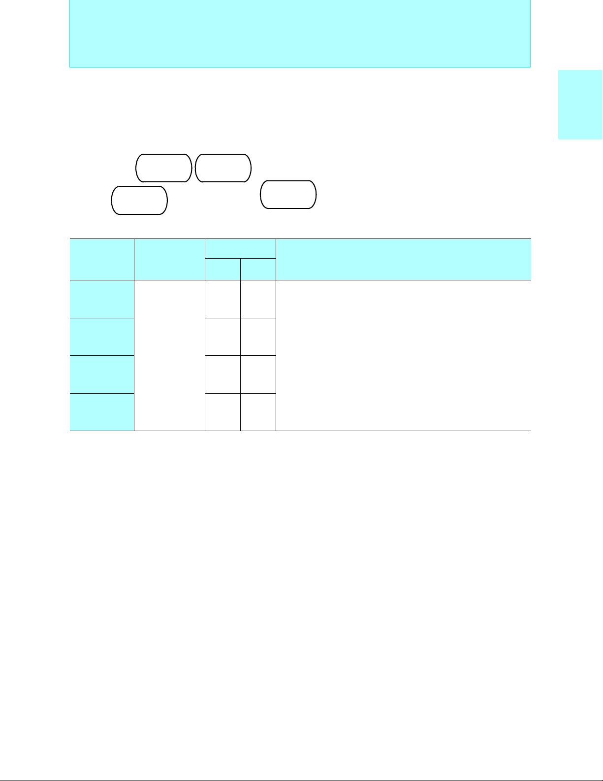
•Registers
Dedicated registers
General-purpose registers: 8 × 8-bit per bank, Max. 32 banks
Dedicated registers
AH
TH TL
RP CCR
16 bits
PC
IX
SP
EP
PS
AL
8 bits
Accumulator
Temporary accumulator
Program counter
Index register
Stack pointer
Extra pointer
Program status
Register bank pointer
Condition code register
• Enhanced interrupt function (prioritized multiple interrupts)
• Powerful operation and transfer functions
Multiplication and division instructions: 8-bit × 8-bit = 16-bit (7.6µs/10MHz), 16-bit ÷ 8-bit = 8-bit (8.4µs/10MHz)
Data transfer: Max. 16-bit
• Number of instructions: 136
Vector
addressing
+127
-128
Relative
addressing
General-purpose
register addressing
Direct
addressing
Immediate
addressing
Extended
addressing
Bit
direct
addressing
0100H+(RP × 8H) →
Index
addressing
Pointer
addressing
General-purpose registers
Max. 32
R7
R6
R5
R4
R3
R2
R1
R0
8 bits
64KB
Upper address
Lower address
4
Page 6

2
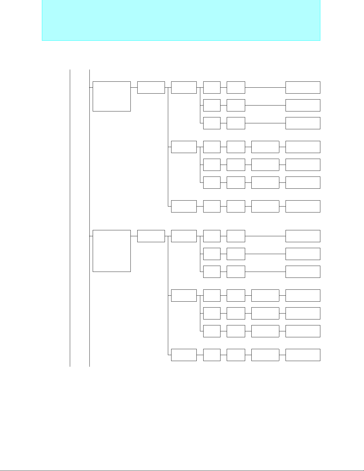
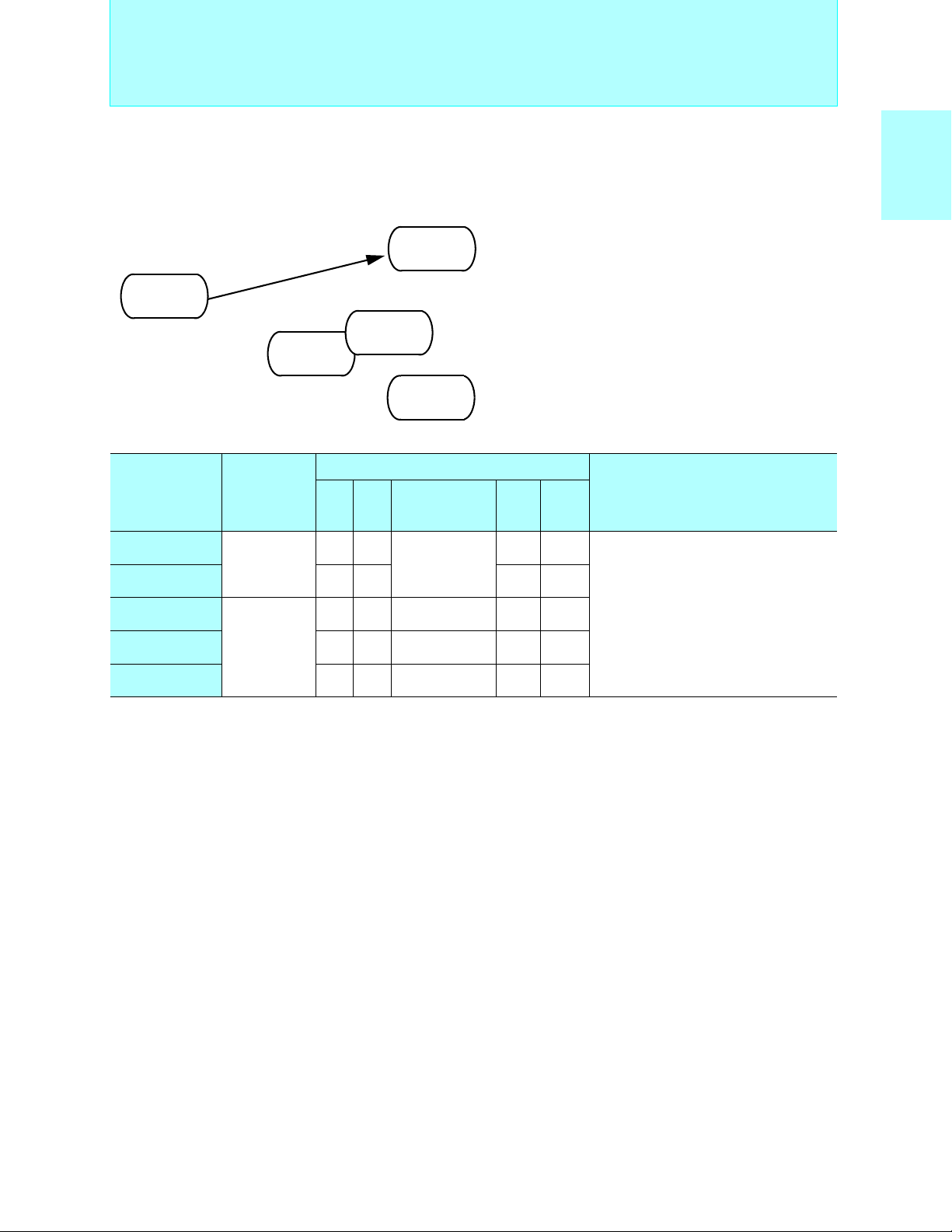
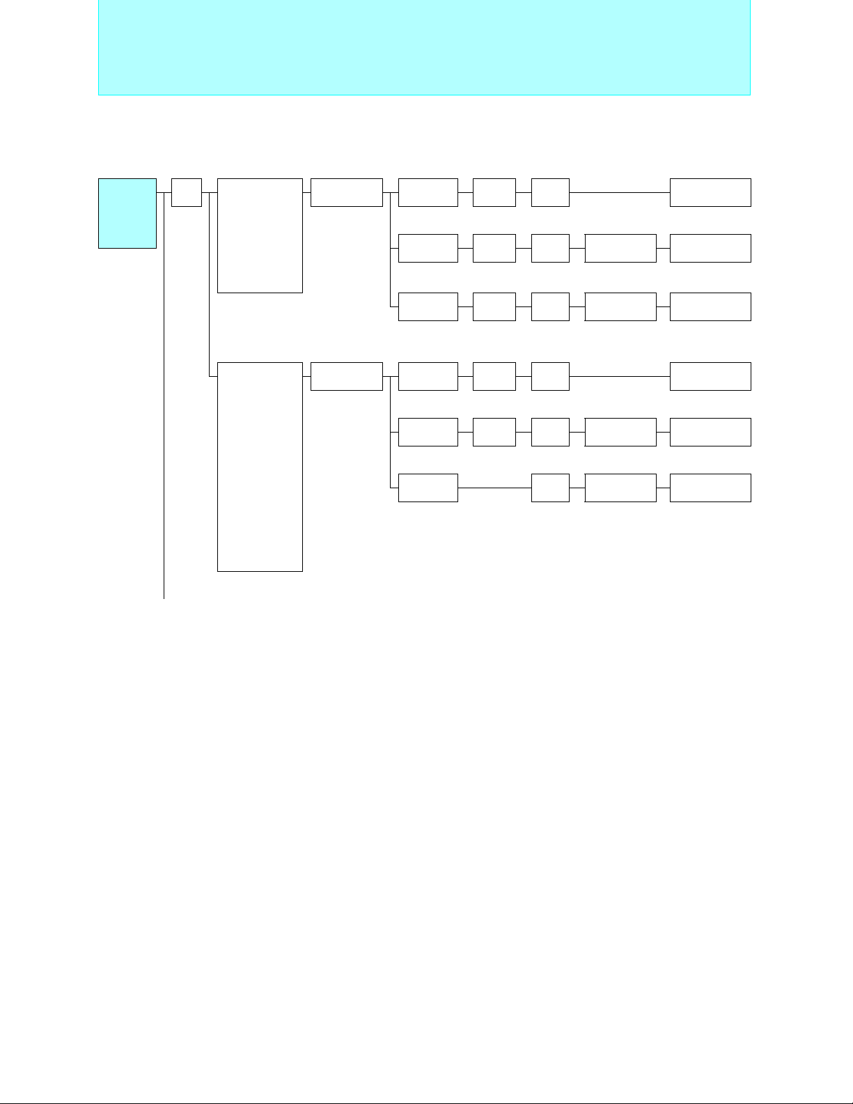
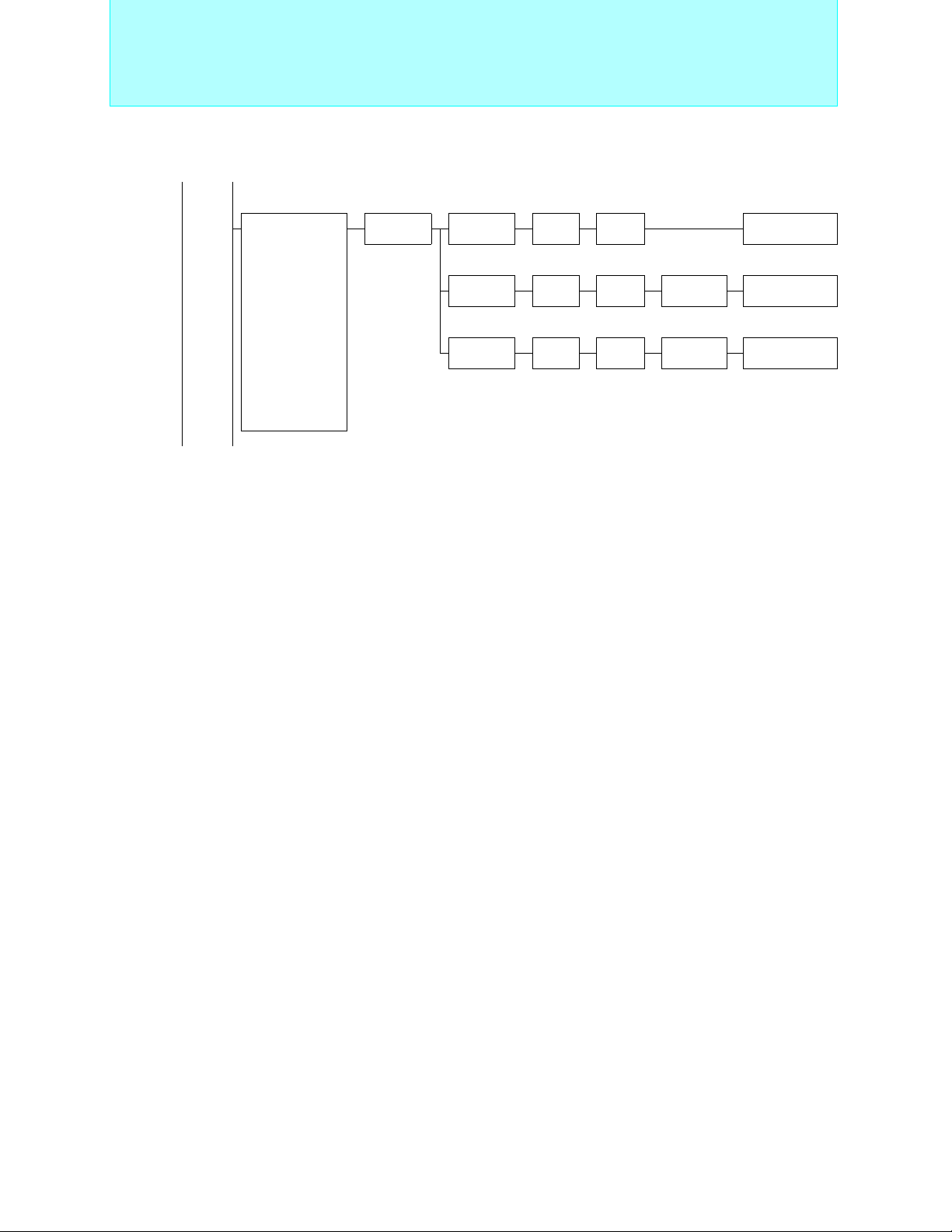
MC-8L Family Product Range
■ F
MC-8LFamily
2
F
5
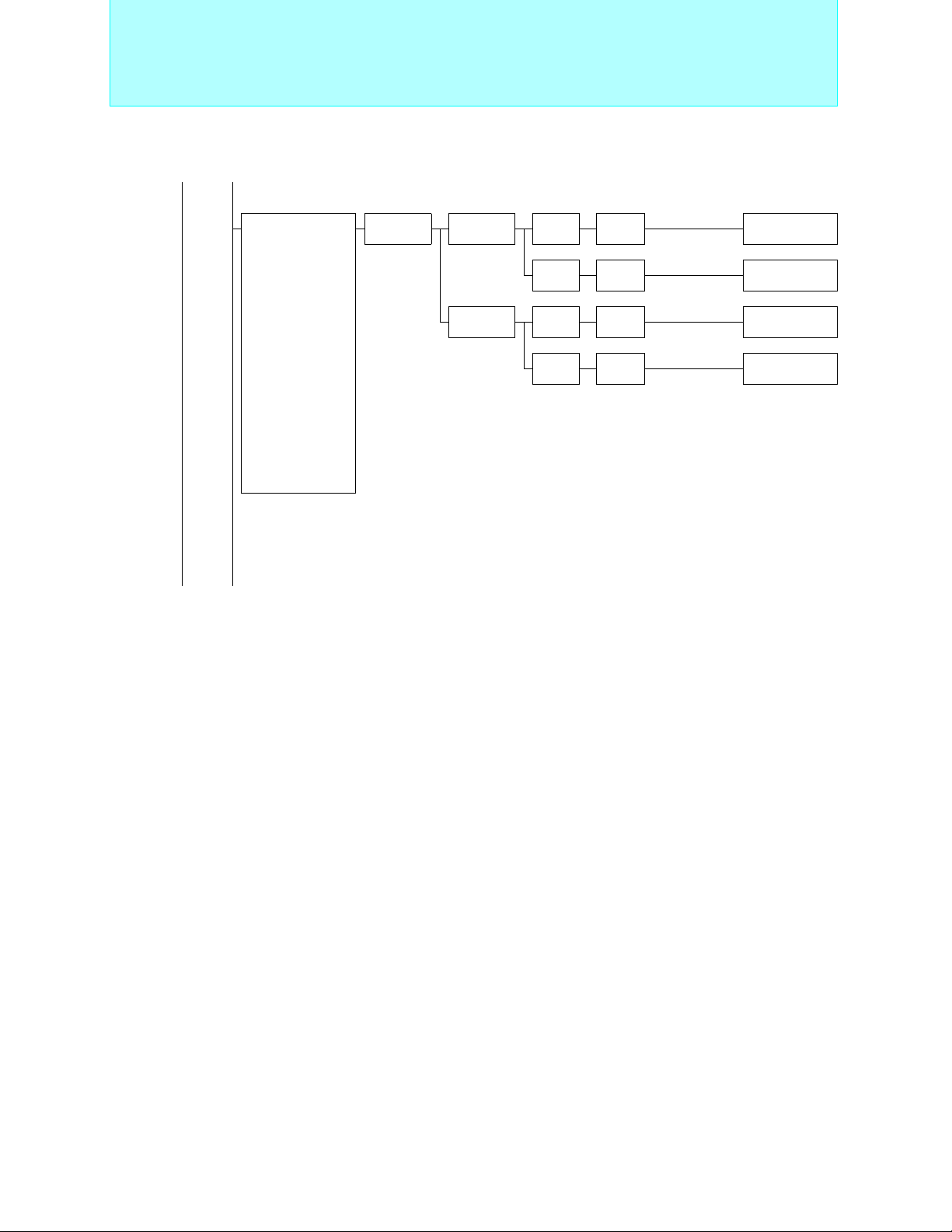
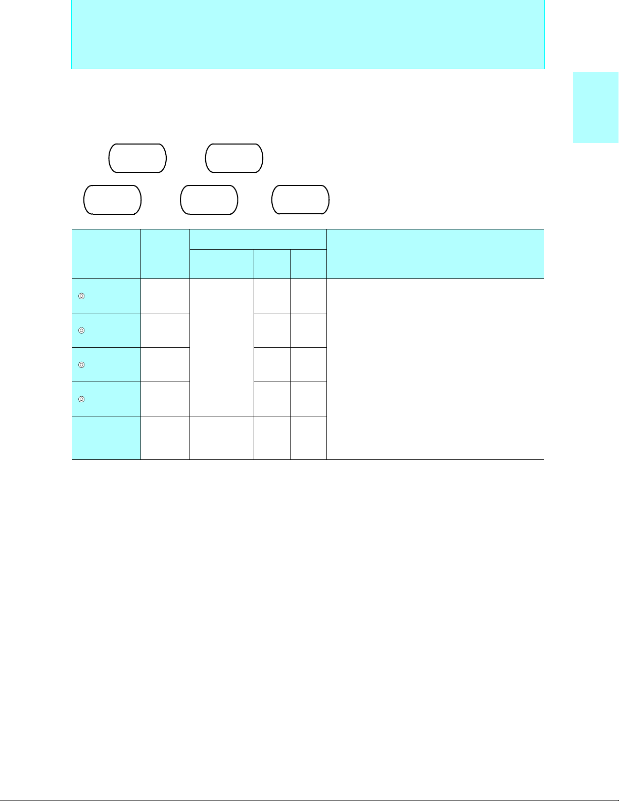
Page 7
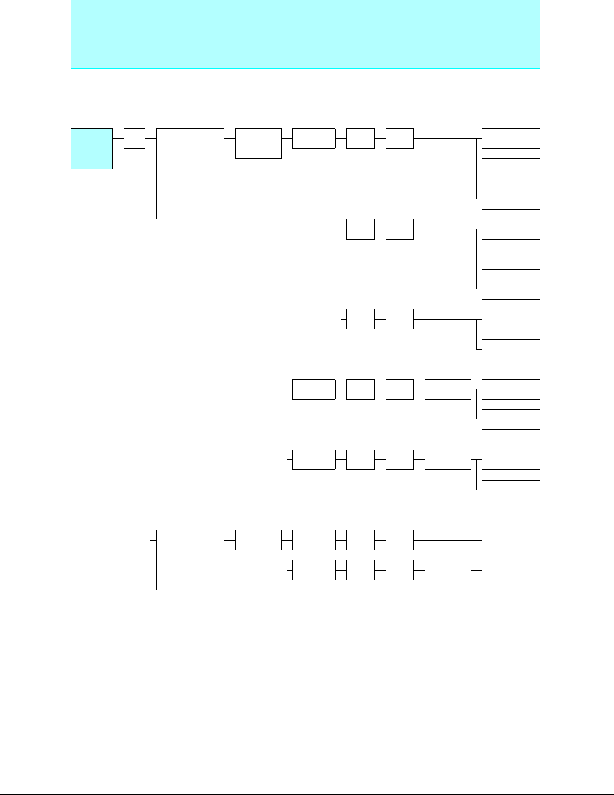
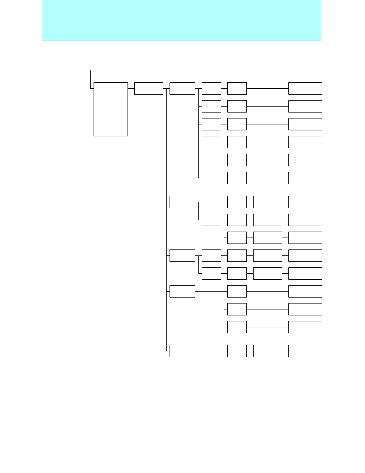
8-bit Proprietary F2MC-8L Family
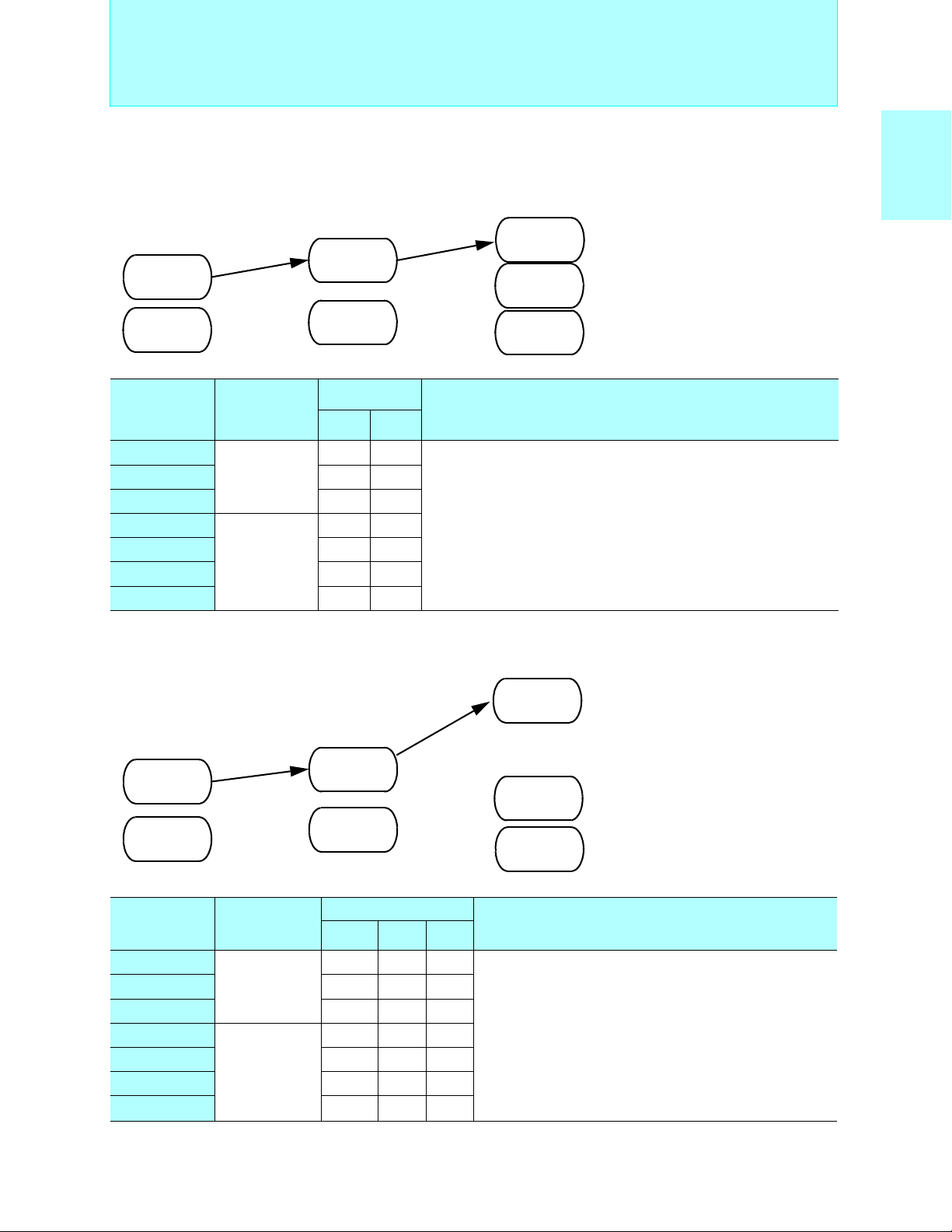
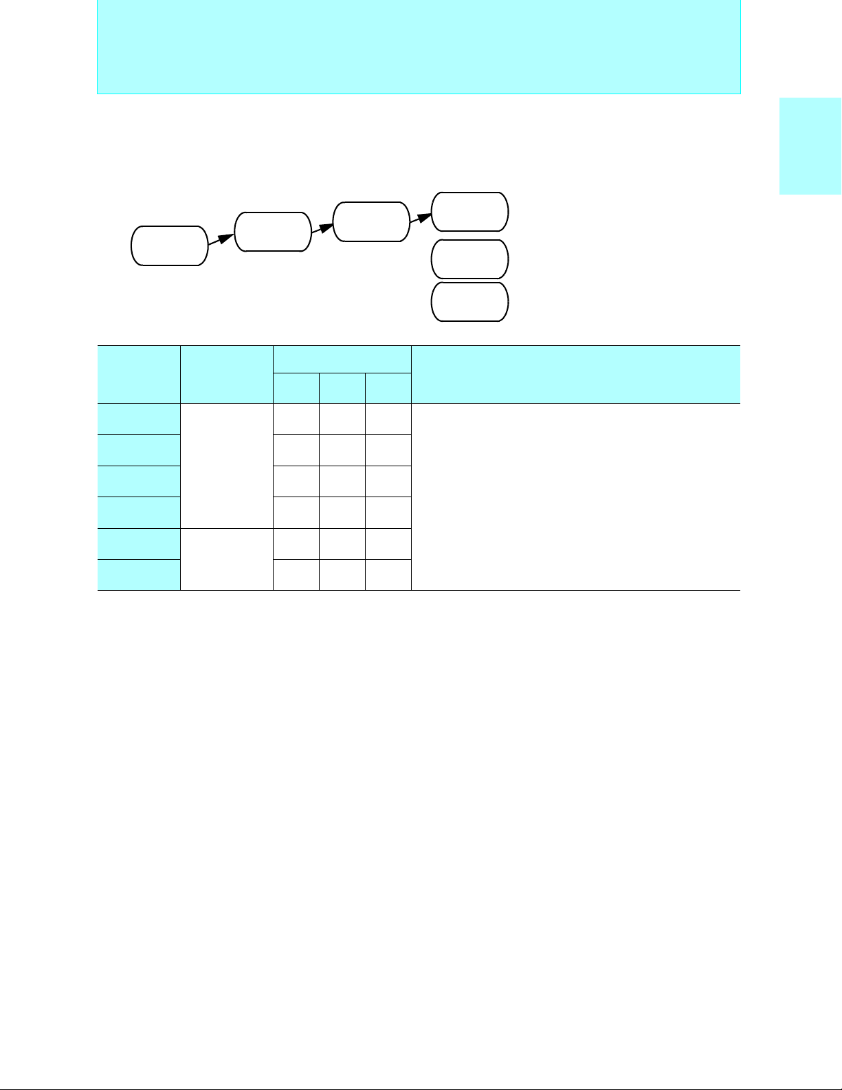
Standard Products
F2MC-8L
Family
Standard
Products
Pin
count
28
Main functions
Small package,
timer/counter
(8-bit × 2ch.),
SIO(8-bit × 1ch.),
A/D converter
(only on A series)
(8-bit × 8ch.)
Series
name
MB89190/
A/AH series
Type ROM RAM Part number
Mass
production
OTPROM 16 KB 256 B
4 KB 128 B MB89191
MB89191A
MB89191AH
8 KB 256 B MB89193
MB89193A
MB89193AH
16 KB 256 B MB89195
MB89195A
Equivalent device
MB89190/A
series
MB89P195
(Continued)
Timer controller,
remote controller
carrier generator,
external interrupt(11ch.)
MB89990
series
Evaluation
device
Mass
production
Evaluation
device
MB89P195A
Evaluation target device
32 KB
(Ext.)
32 KB 128 B MB89997
32 KB
(Ext.)
256 B
256 B
MB89190/A
series
MB89990
series
MB89PV190
MB89PV190A
MB89PV190
6
Page 8
8-bit Proprietary F2MC-8L Family
2
MC-8L Family Standard Products
■ F
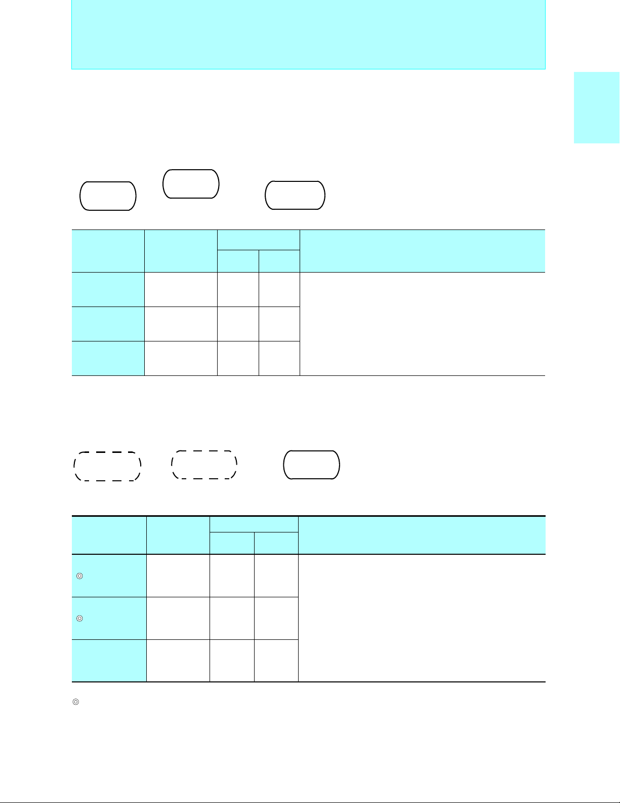
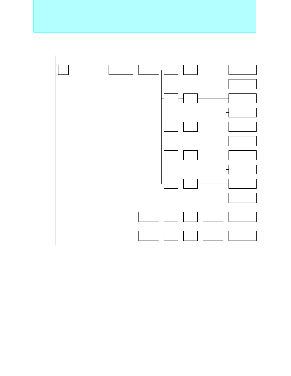
Standard Products
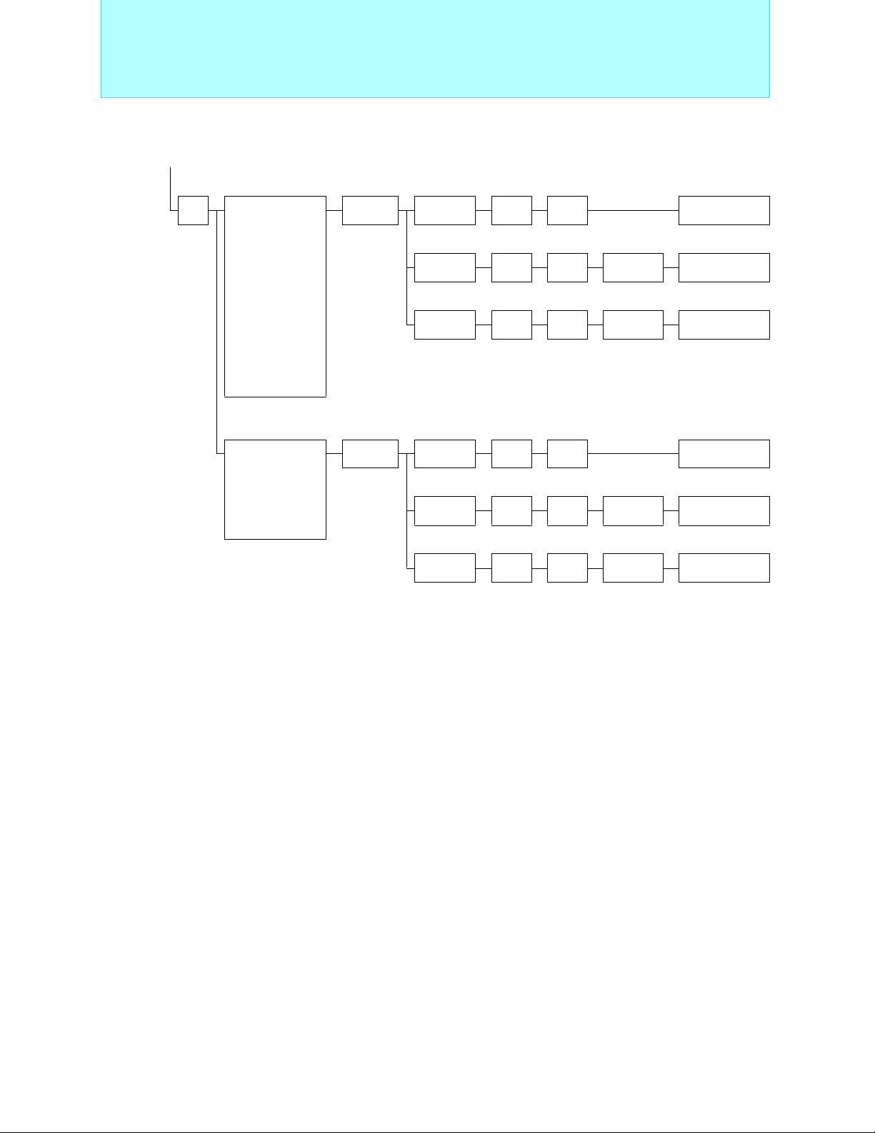
MB89190/190A/190AH Series
Standard products (small package)
MB89193AH
ROM 8KB
MB89191AH
ROM 4KB
RAM 128B
MB89191A
ROM 4KB
RAM 128B
MB89191
ROM 4KB
RAM 128B
MB89193
ROM 8KB
RAM 256B
Operating
Part number
MB89191
MB89191A 28P 28P 28P −
MB89191AH 28P 28P 28P −
MB89193 28P 28P 28P −
MB89193A 28P 28P 28P −
MB89193AH 28P 28P 28P −
MB89195 28P 28P 28P −
MB89195A 28P 28P 28P −
MB89P195
MB89P195A − 28P 28P −
MB89PV190 −−−48C
MB89PV190A −−−48C
: A/D = 3.5V to 6.0V
*
Packages: P - plastic, C - ceramic
power supply
*
voltage
+2.2 to +6.0
+2.7 to +6.0
(V)
SH-DIP DIP SOP MQFP
RAM 256B
MB89193A
ROM8KB
RAM256B
Package
28P 28P 28P −
− 28P 28P −
MB89195A
ROM 16KB
RAM 256B
MB89195
ROM 16KB
RAM 256B
MB89P195A
OTPROM 16KB
RAM 256B
MB89P195
OTPROM 16KB
RAM 256B
• Maximum clock frequency:4.2 MHz
• Minimum execution time:0.95 µs
• Operating temperature range:
-40°C to +85°C
MB89PV190A
Ext. ROM
RAM 256B
MB89PV190
Ext. ROM
RAM 256B
<Evaluation device>
Functions
I/O ports: 22 (20 on MB89190A series)
Timebase timer (WDT): 20-bit × 1ch.
Timer/counter: 8-bit × 2ch. (can operate as 16-bit × 1ch.)
A/D converter: 8-bit × 8ch. (MB89190A series only)
Remote controller carrier generator
SIO : 8-bit × 1ch.
Buzzer output
Interrupts: 5 internal, 11 external
Low-power consumption (standby functions)modes:
Sleep, stop
MC-8LFamily
2
F
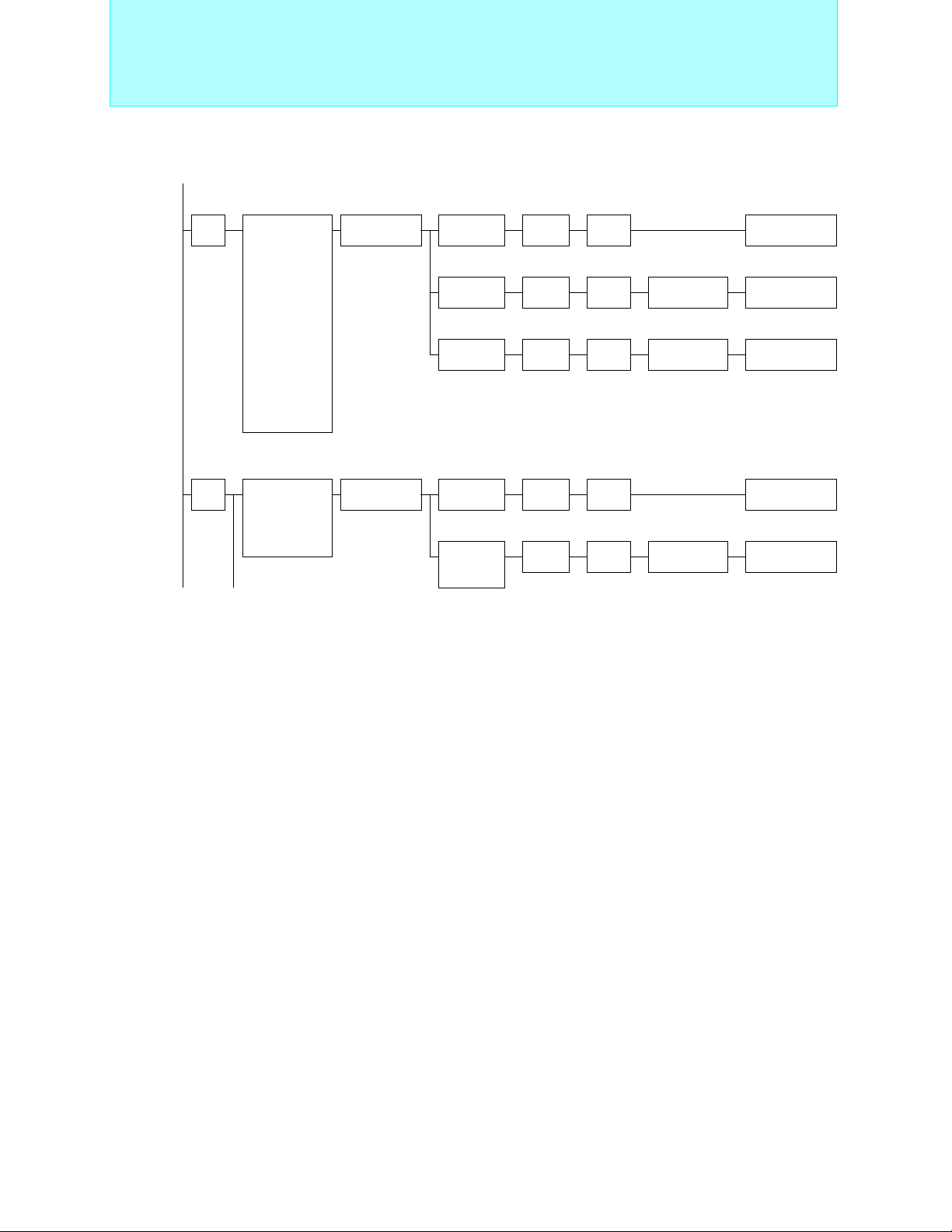
MB89990 Series
Standard products (remote controller, etc.)
MB89997
ROM 32KB
RAM 128B
Operating
Part number
power supply
voltage(V)
MB89997 +2.2 to +6.0 28P 28P −
MB89PV190 +2.7 to +6.0 −−48C
Packages: P - plastic, C - ceramic
MB89PV190
Ext. ROM
RAM 256B
<Evaluation device>
Package
SH-DIP SOP MQFP
• Maximum clock frequency:4.2 MHz
• Minimum execution time:0.95 µs
• Operating temperature range:-40°C to +85°C
Functions
I/O ports: 22
Timebase timer (WDT): 21-bit × 1ch.
Timer/counter: 1ch.
Remote controller carrier generator
Interrupts: 3 internal,11 external
Low-power consumption (standby functions)modes: Sleep, stop
7
Page 9

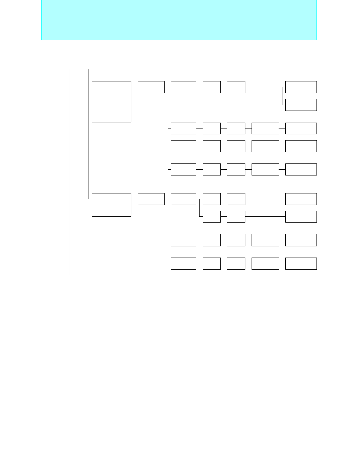
8-bit Proprietary F2MC-8L Family
(Continued)
Pin
count
48
Main functions
DTMF generator,
timer/counter
(8-bit × 2ch.),
SIO(8-bit × 1ch.)
Series
name
MB89170L
series
Type ROM RAM Part number
Mass
production
OTPROM 8 KB 384 B
8 KB 384 B MB89173L
12 KB 512 B MB89174L
Standard Products
Equivalent device
MB89173
MB89173L
MB89P173
(Continued) (Continued)
Evaluation
device
16 KB 512 B
Evaluation target device
32 KB
(Ext.)
1 KB
MB89174
MB89174L
MB89170L
series
MB89P175A
MB89PV170A
8
Page 10

8-bit Proprietary F2MC-8L Family
Standard Products
MB89170L Series
Standard products (low cost)
MB89173L
ROM 8KB
RAM 384B
MB89P173
OTPROM 8KB
RAM 384B
Part number
Operating
power supply
voltage (V)
MB89173L
+2.2 to +6.0
MB89174L 48P −
MB89P173
MB89P175A 48P −
MB89PV170A − 48C
+2.7 to +6.0
Package
QFP MQFP
48P −
48P −
MB89174L
ROM 12KB
RAM 512B
OTPROM 16KB
MB89PV170A
<Evaluation device>
MB89P175A
RAM 512B
Ext. ROM
RAM 1KB
• Maximum clock frequency:
3.58 MHz: MB89P173
7.16 MHz: MB89173L/174L/P175A/PV170A
• Minimum execution time:
0.6 µs to 17.6 µs
• Operating temperature range:
-40°C to +85°C
Functions
I/O ports: 37
Timebase timer (WDT): 21-bit × 1ch.
Timer/counter: 8-bit × 2ch. (can also operate as 16-bit × 1ch.)
SIO : 8-bit × 1ch.
Clock prescaler: 15-bit
Interrupts: 4 internal,11 external
Low-power consumption (standby functions) modes:Sleep,stop
MC-8LFamily
2
F
Packages: P - plastic, C - ceramic
9
Page 11
8-bit Proprietary F2MC-8L Family
Standard Products
(Continued) (Continued)
Main functions
Timer/counter
(8-bit × 2ch.),
SIO(8-bit × 1ch.)
A/D converter
(8-bit × 4ch.),
timer/counter
(8-bit × 2ch. or
16-bit × 1ch.),
SIO(8-bit × 1ch.)
Series
name
MB89120/A
series
MB89130/A
series
Type ROM RAM Part number
Mass
production
OTPROM 4 KB 128 B MB89121 MB89P131
Evaluation
device
Mass
production
4 KB 128 B MB89121
8 KB 256 B MB89123A
16 KB 256 B MB89125A
Equivalent device
8 KB 256 B MB89123A MB89P133A
16 KB 512 B MB89125A MB89P135A
Evaluation target device
32 KB
(Ext.)
4 KB 128 B MB89131
8 KB 256 B MB89133A
16 KB 256 B MB89135A
1 KB
MB89120/A
series
MB89PV130A
(Continued) (Continued)
10
Equivalent device
OTPROM 4 KB 128 B MB89131 MB89P131
8 KB 256 B MB89133A MB89P133A
Evaluation
device
16 KB 512 B
Evaluation target device
32 KB
(Ext.)
1 KB
MB89135A
MB89135L
MB89130/A
series
MB89P135A
MB89PV130A
Page 12
8-bit Proprietary F2MC-8L Family
Standard Products
MB89120/120A Series
Standard products (low cost)
MB89123A
MB89121
ROM 4KB
RAM 128B
MB89P131
OTPROM 4KB
RAM 128B
Operating power
Part number
supply voltage
(V)
MB89121
MB89123A 48P −
+2.2 to +6.0
MB89125A 48P −
MB89P131
MB89P133A 48P −
MB89P135A 48P −
+2.7 to +6.0
MB89PV130A − 48C
Packages: P - plastic, C - ceramic
ROM 8KB
RAM 256B
MB89P133A
OTPROM 8KB
RAM 256B
Package
QFP MQFP
48P −
48P −
MB89130/130A Series
Standard products (built-in A/D converter, low cost)
MB89133A
MB89131
ROM 4KB
RAM 128B
MB89P131
OTPROM 4KB
RAM 128B
ROM 8KB
RAM 256B
MB89P133A
OTPROM 8KB
RAM 256B
MB89125A
ROM 16KB
RAM 256B
MB89P135A
OTPROM 16KB
RAM 512B
MB89PV130A
Ext. ROM
RAM 1KB
• Maximum clock frequency:
4.2 MHz (32.768 kHz)
• Minimum execution time:
0.95 µs to 1.53 µs (61 µs)
• Operating temperature range:
-40°C to +85°C
<Evaluation device>
Functions
I/O ports: 36
Timebase timer (WDT): 21-bit × 1ch.
Timer/counter: 8-bit × 2ch. (can operate as 16-bit × 1ch.)
Remote control carrier generator (on MB89123A/125A/P133A, not included
on MB89121/P131)
SIO : 8-bit × 1ch.
Clock prescaler: 15-bit
Buzzer output
Interrupts: 4 internal, 3 external (MB89121/P131)
Low-power consumption (standby functions)modes:Sleep, watch, stop, sub
4 internal, 11 external (MB89123A/125A/ P133A)
MB89135A
ROM 16KB
RAM 256B
• Maximum clock frequency:
4.2 MHz (32.768 kHz)
• Minimum execution time:
MB89P135A
OTPROM 16KB
RAM 512B
• Operating temperature range:
0.95 µs to 1.53 µs(61 µs)
-40°C to +85°C
MB89PV130A
Ext. ROM
RAM 1KB
<Evaluation device>
MC-8LFamily
2
F
Part number
Operating power
supply voltage
*
(V)
MB89131
MB89133A 48P 48P −
+2.2 to +6.0
Package
SH-DIP QFP MQFP
− 48P −
MB89135A − 48P −
MB89P131
− 48P −
MB89P133A 48P 48P −
MB89P135A − 48P −
+2.7 to +6.0
MB89PV130A −−48C
: A/D = 3.5V to 6.0V
*
Packages: P - plastic, C - ceramic
Functions
I/O ports: 36
Timebase timer (WDT): 21-bit × 1ch.
Timer/counter: 8-bit × 2ch. (can operate as 16-bit × 1ch.)
A/D converter: 8-bit × 4ch.
Remote control carrier generator (on MB89133A/135A/P133A,
not included on MB89131/P131)
SIO : 8-bit × 1ch.
Clock prescaler: 15-bit
Buzzer output
Interrupts: 5 internal, 3 external (MB89131/P131)
Low-power consumption (standby functions)modes:Sleep, watch,
5 internal, 11 external (MB89133A/135A/P133A)
stop, sub
11
Page 13
8-bit Proprietary F2MC-8L Family
(Continued) (Continued)
Main functions
Timer controller,
SIO(8-bit × 1ch.),
A/D converter
(10-bit × 4ch.),
2
I
C controller,
external interrupt
(11ch.)
Series
name
MB89960
series
Type ROM RAM Part number
Mass
production
OTPROM 16 KB 512 B
Standard Products
16 KB 512 B MB89965
MB89965C
Equivalent device
MB89960
series
MB89P965A
(Continued)
PWM timer
(8-bit × 1ch.),
SIO(8-bit × 1ch.)
MB89601R
series
FLASH
ROM
Evaluation
device
Mass
production
OTPROM 4 KB 80 B
Evaluation
device
60 KB
(
FLASH)
32 KB
(Ext.)
4 KB 80 B MB89601R
8 KB 80 B MB89603
32 KB
(Ext.)
1 KB
Evaluation target device
1 KB
Evaluation target device
1 KB
MB89960
series
MB89960
series
Equivalent device
MB89601R
series
MB89601R
series
MB89F969A
MB89PV960
MB89P601
MB89PV620
12
Page 14
8-bit Proprietary F2MC-8L Family
Standard Products
MB89960 Series
Standard products (built-in A/D converter, low cost)
MB89F969A
FLASH ROM 60KB
RAM 512B
MB89965C
MB89965
ROM 16KB
RAM 512B
ROM 16KB
RAM 512B
Operating
Part number
MB89965
power supply
voltage (V)
LQFP QFP MQFP
48P
( 7 × 7mm)
+3.5 to +5.5
MB89965C
MB89P965A
MB89F969A
+3.5 to +5.5
48P
( 7 × 7mm)
48P
( 7 × 7mm)
64P
( 12 × 12mm)
MB89PV960 −−48C
MB89P965A
ROM 16KB
RAM 512B
Package
48P
( 10 × 10mm,
× 12mm)
12
48P
( 10 × 10mm,
12
× 12mm)
48P
( 10 × 10mm,
12
× 12mm)
−−
• Maximum clock frequency: 10 MHz (32.768kHz)
• Minimum execution time: 0.4 µs (61µs)
• Operating temperature range:-40°C to +85°C
MB89PV960
Ext. ROM
RAM 1KB
<Evaluation device>
Functions
−
I/O ports: 35
Timebase timer (WDT): 21-bit × 1ch.
Timer/counter: 8-bit × 2ch.
−
SIO : 8-bit × 1ch.
A/D converter: 10-bit × 4ch.
2
I
C bus interface: (built into MB89965C/P965A/
−
Interrupts: 7 internal, 11 external
Low-power consumption (standby functions) modes :
F969A /PV960, equivalent to SMBus
Rev 1.0)
Sleep,watch,stop,sub
MC-8LFamily
2
F
Packages: P - plastic, C - ceramic
MB89601R Series
Standard products (small package)
MB89603
ROM 8KB
MB89601R
ROM 4KB
RAM 80B
MB89P601
OTPROM 4KB
RAM 80B
Operating
Part number
power supply
voltage (V)
MB89601R
MB89603 48P −−
MB89P601
MB89PV620 − 64C 64C
Packages: P - plastic, C - ceramic
+2.2 to +6.0
+2.7 to +6.0
RAM 80B
Package
LQFP MDIP MQFP
48P −−
48P −−
• Maximum clock frequency: 10 MHz
• Minimum execution time: 0.4 µs
• Operating temperature range:
-40°C to +85°C
MB89PV620
Ext. ROM
RAM 1KB
<Evaluation device>
Functions
I/O ports: 33
Timebase timer (WDT): 20-bit × 1ch.
PWM timer: 8-bit × 1ch.
SIO : 8-bit × 1ch.
Interrupts: 3 internal, 1 external
Low-power consumption (standby functions)modes:
Sleep,stop
13
Page 15
8-bit Proprietary F2MC-8L Family
(Continued)
Pin
count
64 PWM timer,
Main
functions
PWC timer,
16-bit timer/
counter,
SIO
(8-bit × 2ch.)
Series
name
MB89610R
series
Type ROM RAM Part number
Mass
production
OTPROM 16 KB 512 B
8 KB 256 B MB89613R
16 KB 512 B MB89615R
Standard Products
Equivalent device
MB89610R
series
MB89P625
(Continued) (Continued)
EPROM 16 KB 512 B
Evaluation
device
32 KB
(Ext.)
1 KB
MB89610R
series
Evaluation target device
MB89610R
series
MB89W625
MB89PV620
14
Page 16
8-bit Proprietary F2MC-8L Family
Standard Products
MB89610R Series
Standard products (general-purpose type)
MB89615R
ROM 16KB
RAM 512B
MB89613R
ROM 8KB
RAM 256B
MB89P625
OTPROM 16KB
RAM 512B
Operating
Part number
power
supply
voltage (V)
MB89613R
+2.2 to +6.0
MB89615R 64P 64P −−
MB89P625
MB89W625 64C −− −−
MB89PV620 −− − 64C 64C
Packages: P - plastic, C - ceramic
+2.7 to +6.0
MB89W625
EPROM 16KB
RAM 512B
MB89PV620
Ext. ROM
RAM 1KB
<Evaluation device>
Package
DIP QFP LQFP MDIP MQFP
64P 64P
64P 64P
64P
(0.5 mm pitch,
0.65mm pitch)
64P
(0.65 mm pitch)
−−
−−
• Maximum clock frequency: 10 MHz
• Minimum execution time: 0.4 µs
• Operating temperature range:
I/O ports: 53
Timebase timer (WDT): 20-bit × 1ch.
Timer/counter: 16-bit × 1ch.
PWM timer: 8-bit × 1ch.
PWC timer: 8-bit × 1ch.
SIO : 8-bit × 2ch.
Buzzer output
Interrupts: 6 internal, 4 external
Low-power consumption (standby functions)
-40°C to +85°C
Functions
modes: Sleep, stop
MC-8LFamily
2
F
15
Page 17
8-bit Proprietary F2MC-8L Family
(Continued) (Continued)
Main
functions
A/D converter
(8-bit × 8ch.),
PWM timer,
PWC timer,
16-bit timer/
counter,
SIO
(8-bit × 2ch.)
Series
name
MB89620/R
series
Type ROM RAM Part number
Mass
production
OTPROM 16 KB 512 B
Standard Products
8 KB 256 B MB89623R
16 KB 512 B MB89625R
24 KB 768 B MB89626R
32 KB 1 KB MB89627R
24 KB 3 KB MB89628R
32 KB 3 KB MB89629R
Equivalent device
MB89623R
MB89625R
MB89P625
(Continued)
32 KB 1 KB
4 KB
EPROM 16 KB 512 B
32 KB 1 KB
No ROM 256 B MB89T623
512 B MB89T625
1 KB MB89T627R
Evaluation target device
Evaluation
device
32 KB
(Ext.)
1 KB
MB89626R
MB89627R
MB89628R
MB89629R
MB89623R
MB89625R
MB89626R
MB89627R
MB89620/R
series
MB89P627
MB89P629
MB89W625
MB89W627
MB89PV620
16
Page 18
MB89620/620R Series
z
Standard products (built-in A/D converter)
MB89T625
MB89T623
Ext. ROM
RAM 256B
MB89623R
ROM 8KB
RAM 256B
Ext. ROM
RAM512B
MB89W625
EPROM 16KB
RAM 512B
MB89629R
ROM 32KB
RAM 3KB
MB89T627R
Ext. ROM
RAM 1KB
MB89P627
OTPROM 32KB
RAM 1KB
MB89PV620
Ext. ROM
RAM 1KB
<Evaluation device>
MB89W627
EPROM 32KB
RAM 1KB
• Maximum clock frequency: 10 MH
• Minimum execution time: 0.4 µs
• Operating temperature range:
-40°C to +85°C
MC-8LFamily
2
F
Operating
Part number
MB89623R
MB89625R 64P 64P −−
MB89626R 64P 64P
MB89627R 64P 64P −−
MB89628R 64P 64P −−−
MB89629R 64P 64P −−−
MB89T623
MB89T625 64P 64P 64P −−
MB89T627R 64P 64P
MB89P625 64P 64P −−
MB89P627 64P 64P −−
MB89P629 64P 64P −−−
power supply
voltage* (V)
+2.2 to +6.0
+2.7 to +6.0
SH-DIP
QFP LQFP MDIP MQFP
64P 64P
64P 64P 64P −−
Package
64P
(0.5 mm pitch)
64P
(0.65 mm pitch)
64P
(0.65 mm pitch)
−−
−−
I/O ports: 53
Timebase timer(WDT): 20-bit × 1ch.
Timer/counter: 16-bit × 1ch.
PWM timer: 8-bit × 1ch.
PWC timer: 8-bit × 1ch.
A/D converter: 8-bit × 8ch.
−−
SIO : 8-bit × 2ch.
Buzzer output
Interrupts: 7 internal, 4 external
Low-power consumption (standby functions) modes: Sleep, stop
MB89W625 64C −−−−
MB89W627 64C −−−−
MB89PV620 −− − 64C 64C
*: A/D = 3.5V to 6.0V
Packages: P - plastic, C - ceramic
Functions
17
Page 19
8-bit Proprietary F2MC-8L Family
(Continued)
Pin
count
80 A/D converter
Main
functions
(8-bit × 8ch.),
D/A converter
(8-bit × 2ch.),
PWM timer,
PWC timer,
SIO
(8bit × 2ch.)
Series
name
MB89640
series
Type ROM RAM Part number
Mass
production
OTPROM 32 KB 1 KB
Evaluation
device
8 KB 256 B MB89643
16 KB 512 B MB89645
24 KB 768 B MB89646
32 KB 1 KB MB89647
32 KB
(Ext.)
Standard Products
Equivalent device
MB89640
series
Evaluation target device
1 KB
MB89640
series
MB89P647
MB89PV640
(Continued)
18
Page 20
8-bit Proprietary F2MC-8L Family
Standard Products
MB89640 Series
Standard products (built-in A/D, D/A converter)
MB89646
MB89645
MB89643
ROM 8KB
RAM 256B
ROM 16KB
RAM 512B
Operating
Part number
MB89643
MB89645 80P 80P −
MB89646 80P 80P −
MB89647 80P 80P −
MB89P647
MB89PV640 −−80C
power supply
*
voltage
+2.2 to +6.0
+2.7 to +6.0
(V)
QFP LQFP MQFP
80P 80P −
80P 80P −
ROM 24KB
RAM 768B
Package
MB89647
ROM 32KB
RAM 1KB
MB89P647
OTPROM 32KB
RAM 1KB
MB89PV640
Ext. ROM
RAM 1KB
<Evaluation device>
• Maximum clock frequency:
10 MHz (32.768 kHz)
• Minimum execution time:
0.4 µs to 6.4 µs (61 µs)
• Operating temperature range:
-40°C to +85°C
Functions
I/O ports: 65
Timebase timer (WDT): 21-bit × 1ch.
Timer/counter: 16-bit × 1ch.
PWM timer: 8-bit × 2ch.
PWC timer: 8-bit × 1ch.
A/D converter: 8-bit × 8ch.
D/A converter: 8-bit × 2ch.
SIO : 8-bit × 2ch.
Clock prescaler: 15-bit
Buzzer output function
Interrupts: 9 internal, 9 external
Low-power consumption (standby functions) modes: Sleep,
watch,stop,sub
MC-8LFamily
2
F
: A/D = D/A = 3.5V to 6.0V
*
Packages: P - plastic, C - ceramic
19
Page 21
8-bit Proprietary F2MC-8L Family
Standard Products
(Continued)
Pin
count
100
Main functions
2
I
C(Equivalent
toSMBus),
Bridge circuit,
Comparator,
UART/SIO,
LCD controller
(14seg. × 4com.) ,
A/D converter
(10 bit × 12 ch) ,
D/A converter
(8 bit × 2 ch.) ,
8/16bit timer
(8 bit × 2 ch. / 16
bit × 1 ch.)
MSK modem output,
A/D converter
(8-bit × 8ch.),
UART,
SIO (8-bit × 1ch.)
Series
name
MB89570
series
MB89680
series
Type ROM RAM Part number
Mass
production
OTPROM 60 KB 3 KB
Evaluation
device
Mass
production
OTPROM 60 KB 2 KB
Evaluation
device
32 KB 3 KB MB89577
Equivalent device
MB89570
series
Evaluation target device
48 KB
(Ext.)
60 KB 2 KB MB89689
60 KB
(Ext.)
3 KB
Evaluation target device
2 KB
MB89570
series
Equivalent device
MB89680
series
MB89680
series
MB89P579A
MB89PV570
MB89P689
MB89PV680
20
Page 22
8-bit Proprietary F2MC-8L Family
Standard Products
MB89570 Series
Standard products
MB89P579A
OTPROM 60KB
MB89577
ROM 32KB
RAM 3KB
Operating
Part number
power supply
voltage(V)
MB89577
MB89P579A 100P 100P −
+2.7 to +3.7
MB89PV570 −−100C
Packages: P - plastic, C - ceramic
RAM 3KB
Package
QFP LQFP MQFP
100P 100P −
• Maximum clock frequency:10 MHz (32.768 kHz)
• Minimum execution time:0.40 µs
MB89PV570
Ext. ROM
RAM 3KB
<Evaluation device>
• Operating temperature range:-40°C to +85°C
Functions
I/O ports: 82
Timebase timer (WDT): 21-bit × 1ch.
Timer/counter: 8-bit × 2ch. (can operate as 16-bit × 1ch.)
16 bit Timer/counter × 1ch.
2
I
C(Equivalent toSMBus): 1ch.
SIO/UART: 1ch.
A/D converter: 10-bit × 12ch.
D/A converter: 8-bit × 2ch.
LCD controller: 56 elements, 10 to 14 segments, 2 to 4 common
Comparator
Interrupts: 4 external
Low-power consumption (standby functions) modes:
7 × 8-bit LCD display RAM
Sleep, watch,stop,sub
MC-8LFamily
2
F
MB89680 Series
Standard products (100-pin, MSK modem output)
MB89689
ROM 60KB
RAM 2KB
MB89P689
OTPROM 60KB
RAM 2KB
MB89PV680
Ext. ROM
RAM 2KB
<Evaluation device>
Operating
Part number
MB89689 +2.2 to +6.0 100P −
MB89P689
MB89PV680 − 100C
*: A/D = 3.5V to 6.0V
Packages: P - plastic, C - ceramic
power supply
*
voltage
+2.7 to +6.0
(V)
Package
QFP MQFP
100P −
• Maximum clock frequency:
8 MHz (32.768 kHz)
• Minimum execution time:
0.5 µs to 8.0 µs (61 µs)
• Operating temperature range:
-40°C to +85°C
Functions
I/O ports: 85
Timebase timer (WDT): 21-bit × 1ch.
Timer/counter: 8-bit × 2ch. (can operate as 16-bit × 1ch.)
PWM timer: 8-bit × 1ch.
A/D converter: 8-bit × 8ch.
SIO : 8-bit × 1ch.
UART: 6-bit to 9-bit × 1ch.
MSK software modem output: 1200 bps, 2400 bps
MSK software modem timer: 1ch.
(built-in noise reduction circuit)
Clock prescaler: 15-bit
Interrupts: 10 internal, 16 external
Low-power consumption (standby functions) modes:Sleep, watch, stop,
sub
21
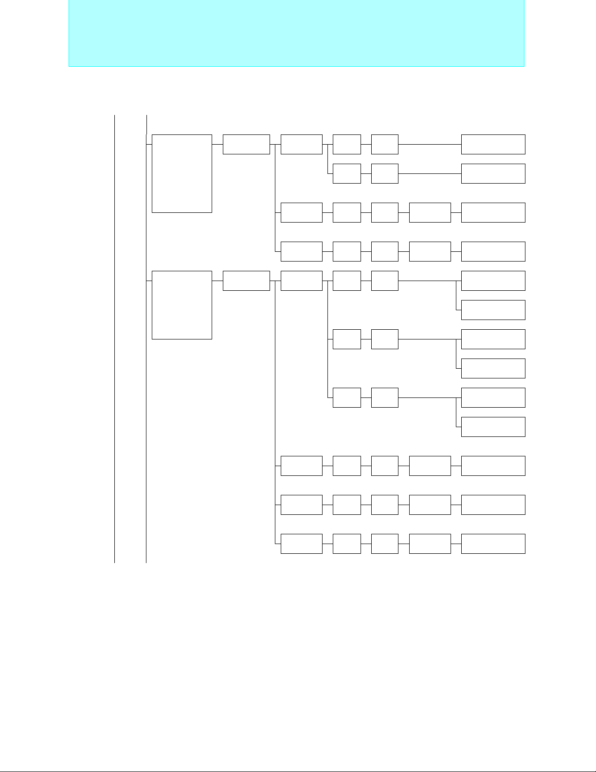
Page 23
8-bit Proprietary F2MC-8L Family
Internal UART Products
F2MC-8L
Family
Internal
UART
Products
Pin
count
30
Main
functions
A/D converter
(10bit × 8ch.)
UART/SIO
PWM timer
(8bit × 1ch.)
PPG timer
(12bit × 1ch.)
Timer counter
with 8/16 bit
capture
A/D converter
(10 bit × 8 ch) ,
8/16 bit timer
counter (1 ch) ,
UART for LIN
(1 ch) ,
SIO (1 ch) ,
Interrupts
(3 ch) ,
PWM timer
(8 bit × 1 ch) ,
PPG timer
(12 bit × 1 ch) ,
CR Oscillation
circuit
Series name Type ROM RAM Part number
MB89930A/B
series
MB89210
series
Mass
production
OTPROM 16 KB 512 B
Evaluation
device
Mass
production
OTPROM 16 KB 512 B MB89215 MB89P215 *
Evaluation
device
16 KB 512 B MB89935B
Equivalent device
MB89930A/B
series
Evaluation target device
16 KB
(Ext.)
16 KB 512 B MB89215 *
512 B
2 KB
MB89930A/B
series
Equivalent device
Evaluation target device
MB89210
series
* :Under development
MB89P935B
MB89PV930A
MB89PV210
(Continued)
22
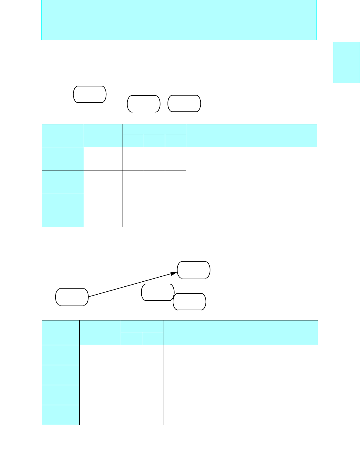
Page 24
8-bit Proprietary F2MC-8L Family
■ F2MC-8L Family UART Products
MB89930A/B Series
Standard products (built-in UART, compact type)
MB89P935B
MB89935B
ROM 16KB
RAM 512B
OTPROM 16KB
RAM 512B
MB89PV930A
Ext. ROM
RAM 512B
<Evaluation device>
Internal UART Products
• Maximum clock frequency: 10 MHz
• Minimum execution time: 0.4 µs
• Operating temperature range:
−40°C to +85°C
MC-8LFamily
2
F
Operating
Part number
power supply
voltage (V)
MB89935B +2.2 to +5.5 30P -
MB89P935B +3.0 to +5.5 30P -
MB89PV930A +2.7 to +5.5 - 48C
Packages: P - plastic, C - ceramic
Package
SSOP MQFP
MB89210 Series
UART for LIN, Compact type, CR Oscillation circuit
MB89215
ROM 16KB
RAM 512B
Under development
Part number
power supply
MB89P215
OTPROM 16KB Ext. ROM
RAM 512B
Under development
Operating
voltage (V)
Package
SSOP MQFP
I/O ports: 21
A/D converter: 10-bit × 8 ch.
UART/SIO: 1 ch.
PWM timer: 8-bit × 1 ch.
PPG timer: 12-bit × 1ch.
Timer counter with 8/16-bit capture
Timebase timer: 21-bit × 1ch.
Interrupts: 11 external
Low-power consumption (standby functions) modes: Sleep, stop
MB89PV210
RAM 2KB
<Evaluation device>
Functions
• Maximum clock frequency: 12.5 MHz
µ
• Minimum execution time: 0.32
• Operating temperature range:
s
−40°C to +85°C
Functions
MB89215
MB89P215
MB89PV210 +3.5 to +5.5 48C
Packages: P - plastic, C - ceramic
: Under development
+3.5 to +5.5 30P
+3.5 to +5.5 30P
I/O ports: 21
A/D converter: 10-bit ×8 ch.
Timer counter with 8/16-bit capture : 1 ch.
Timebase timer: 21-bit × 1 ch.
PWM timer: 8-bit × 1 ch.
PPG timer: 12-bit × 1 ch.
UART for LIN : 1 ch.
SIO : 1 ch.
Interrupts: 3 external
CR Oscillation circuit (MB89215, MB89P215)
Low-power consumption (standby functions) modes: Sleep, stop
23
Page 25
8-bit Proprietary F2MC-8L Family
(Continued)
Pin
count
48
Main
functions
A/D converter
(10bit × 8ch.)
Timer/counter
(8 bit × 4 ch.,
can operate as
16-bit)
UART/SIO
(2 ch.)
Interrupts
(9 ch.)
PWM timer
(8 bit × 1 ch.)
PWC timer
(8 bit × 1 ch.)
Clock
prescaler
Buzzer output
Series name Type ROM RAM Part number
MB89470
series
Mass
production
OTPROM 16 KB 512 B MB89475 MB89P475
Evaluation
device
16 KB 512 B MB89475
16 KB
(Ext.)
Internal UART Products
Equivalent device
Evaluation target device
1 KB
MB89470
series
MB89PV470
UART (1ch.),
64
PWM timer
(8-bit × 2ch.),
SIO
(8-bit × 1ch.)
(Continued) (Continued)
MB89810A
series
Mass
production
OTPROM
Evaluation
device
24 KB 2 KB MB89816A
Evaluation target device
32 KB 2 KB
MB89810A
series
MB89P817A
24
Page 26
8-bit Proprietary F2MC-8L Family
Internal UART Products
MB89470 Series
Standard products (built-in UART, compact type)
MB89475
ROM 16 KB
RAM 512 B
Operating
Part number
power supply
voltage (V)
MB89475 +2.2 to +5.5 48P −
MB89P475 +3.5 to +5.5 48P −
MB89PV470 +2.7 to +5.5 − 48C
Packages: P - plastic, C - ceramic
MB89P475
OTPROM 16 KB
RAM 512 B
Package
LQFP MQFP
• Maximum clock frequency:
12.5 MHz (32.768 kHz)
MB89PV470
Ext. ROM
RAM 1 KB
<Evaluation device>
• Minimum execution time:
0.32 µs (61 µs)
• Operating temperature range:
-40°C to +85°C
Functions
I/O ports: 39
A/D converter: 10-bit × 8 ch.
Timer/counter: 8-bit × 4 ch. (16-bit × 2ch.)
Timebase timer (WDT): 21-bit × 1 ch.
PWM timer: 8-bit × 1 ch.
PWC timer: 8-bit × 1 ch.
UART/SIO: 2ch.
Interrupts: 5 ch. (Level) + 4 ch. (edges)
Clock prescaler
Buzzer output
Low-power consumption (standby functions) modes: Sleep, stop,
sub, clock
MC-8LFamily
2
F
MB89810A Series
Standard products (built-in UART, large memory 8-bit microcontroller)
MB89816A
ROM 24KB
RAM 2KB
MB89P817A
OTPROM 32KB
RAM 2KB
Operating
Part number
power supply
voltage (V)
MB89816A +2.2 to +6.0 64P
MB89P817A +2.7 to +6.0 64P
Packages: P - plastic
Package
QFP
I/O ports: 53
Timebase timer (WDT): 20-bit × 1 ch.
Timer/counter: 16-bit × 1ch.
PWM timer: 8-bit × 2ch.
SIO: 8-bit × 1ch.
UART: 5-, 7- or 8-bit × 1 ch.
Clock prescaler: 12-bit
Interrupts: 7 internal, 8 external
Low-power consumption (standby functions) modes: Sleep, watch, stop, sub
• Maximum clock frequency:
5 MHz (32.768 kHz)
• Minimum execution time:
0.8 µs (61 µs)
• Operating temperature range:
-40°C to +85°C
Functions
25
Page 27
8-bit Proprietary F2MC-8L Family
(Continued) (Continued)
Main
functions
UART (1 ch.),
A/D converter
(10-bit × 8 ch.),
SIO
(8-bit × 1 ch.)
Series
name
MB89630/R
series
Type ROM RAM Part number
Mass
production
OTPROM 32 KB 1 KB
Internal UART Products
16 KB 512 B MB89635
MB89635R
24 KB 768 B MB89636R
32 KB 1 KB MB89637
MB89637R
Equivalent device
MB89630/R
series
MB89P637
(Continued) (Continued)
EPROM 32 KB 1 KB
No ROM 512 B MB89T635
1 KB MB89T637
Evaluation target device
Evaluation
device
32 KB
(Ext.)
1 KB
MB89630/R
series
MB89630/R
series
MB89W637
MB89T635R
MB89T637R
MB89PV630
26
Page 28
8-bit Proprietary F2MC-8L Family
MB89630/630R Series
Standard products (A/D converter, built-in UART)
MB89T635R
Ext. ROM
MB89635R
ROM 16KB
RAM 512B
MB89635
ROM 16KB
RAM 512B
RAM 512B
MB89T635
Ext. ROM
RAM 512B
MB89636R
ROM 24KB
RAM 768B
MB89P637
OTPROM 32KB
RAM 1KB
MB89637R
ROM 32KB
RAM 1KB
MB89637
ROM 32KB
RAM 1KB
MB89W637
EPROM 32KB
RAM 1KB
<Evaluation device>
MB89T637R
Ext. ROM
RAM 1KB
MB89T637
Ext. ROM
RAM 1KB
MB89PV630
Ext. ROM
RAM 1KB
Internal UART Products
• Maximum clock frequency:
10 MHz (32.768 kHz)
• Minimum execution time:
0.4 µs to 6.4 µs (61 µs)
• Operating temperature range:
-40°C to +85°C
MC-8LFamily
2
F
Part number
MB89635
Operating
power supply
voltage
*
(V)
SH-DIP
64P 64P 64P −−
Package
QFP LQFP MDIP MQFP
MB89635R 64P 64P 64P −−
MB89636R 64P 64P 64P −−
+2.2 to +6.0
MB89637 64P 64P 64P −−
MB89637R 64P 64P 64P −−
MB89P637
64P 64P −−−
MB89W637 64C −− − −
MB89T635 64P 64P 64P −−
MB89T635R 64P 64P 64P −−
+2.7 to +6.0
MB89T637 64P 64P 64P −−
I/O ports: 53
Timebase timer (WDT): 21-bit × 1ch.
Timer/counter: 16-bit × 1ch.
PWM timer: 8-bit × 2ch.
PWC timer: 8-bit × 1ch.
A/D converter: 10-bit × 8ch.
SIO: 8-bit × 1ch.
UART: 8-bit × 1ch. (switchable between two I/
O ports)
Clock prescaler: 15-bit
Buzzer output
Interrupts: 10 internal, 4 external
Low-power consumption (standby functions)
MB89T637R 64P 64P 64P −−
MB89PV630 −−−64C 64C
*: A/D = 3.5V to 6.0V
Packages: P - plastic, C - ceramic
Functions
modes: Sleep, watch, stop, sub
27
Page 29
8-bit Proprietary F2MC-8L Family
(Continued) (Continued)
Main functions
Real time I/O,
UART,
SIO,
A/D converter
(8-bit × 8ch.),
PWM timer
(8-bit × 1ch.)
Series
name
MB89660/R
series
Type ROM RAM Part number
Mass
production
OTPROM 16 KB 512 B
Internal UART Products
8 KB 256 B MB89663
MB89663R
16 KB 512 B MB89665
MB89665R
Equivalent device
MB89660/R
series
MB89P665
UART,
SIO,
UART/SIO,
2
I
C bus interface
(MB89537AC/
538AC/P538/
PV530),
PWM timer
(8-bit × 2ch.),
timer/counter
(16-bit × 1ch.),
PWC timer
(8-bit × 2ch.),
PPG timer
(12-bit× 2ch.,
6-bit × 1ch.,
A/D converter
(10-bit × 8ch.)
MB89530A
series
EPROM/
evaluation
version
Mass
production
OTPROM 48 KB 2 KB
FLASH 48 KB 2 KB
16 KB 512 B
16 KB 512 B MB89535A
32 KB 1 KB MB89537A
48 KB 2 KB MB89538A
Evaluation target device
MB89660/R
series
Equivalent device
MB89530A
series
MB89530A
series
MB89W665
MB89537AC
MB89538AC
MB89P538
MB89F538
MB89F538L *
Evaluation
device
(Continued) (Continued) * : Under development
48 KB
(Ext.)
Evaluation target device
2 KB
MB89530A
series
MB89PV530
28
Page 30
)
8-bit Proprietary F2MC-8L Family
MB89660/660R Series
Standard products (for real-time pulse I/O control)
MB89663R
ROM 8KB
RAM 256B
MB89663
ROM 8KB
RAM 256B
MB89665
ROM 16KB
RAM 512B
MB89W665
MB89P665
OTPROM 16KB
RAM 512B
EPROM 16KB
<Evaluation device>
MB89665R
ROM 16KB
RAM 512B
RAM 512B
Internal UART Products
• Maximum clock frequency: 10 MHz
• Minimum execution time: 0.4 µs
• Operating temperature range:
-40°C to +85°C
MC-8LFamily
2
F
Operating
Part number
power supply
voltage* (V)
MB89663
MB89663R 64P 64P
+2.2 to +6.0
MB89665 64P 64P
MB89665R 64P 64P
MB89P665
+2.7 to +6.0
MB89W665 64C −
Package
SH-DIP QFP
64P 64P I/O ports: 52
64P 64P
Timebase timer (WDT): 20-bit × 1ch.
Timer/counter: 8-bit × 2ch. (can operate as 16-bit × 1ch.)
PWM timer: 8-bit × 1ch.
A/D converter: 8-bit × 8ch.
SIO: 8-bit × 1ch.
Real time I/O
Input capture: 16-bit × 2ch. (external trigger edge selection)
Output compare: 16-bit × 2ch.
UART: 7-bit to 9-bit × 1ch.
Interrupts: 11 internal, 4 external
Low-power consumption (standby functions) modes: Sleep, stop, hardware
standby
*: A/D = 3.5V to 6.0V
Packages: P - plastic, C - ceramic
MB89530A Series
Standard products (telephones, mobileproducts, etc.)
MB89F538
FLASH ROM 48KB
RAM 2KB
MB89535A
ROM 32KB
RAM 512B
MB89537AC
MB89537A
ROM 32KB
RAM 1KB
ROM 32KB
RAM 1KB
MB89538A
ROM 48KB
RAM 2KB
MB89538AC
ROM 48KB
RAM 2KB
Functions
16-bit timer:Operating clock frequency (0.4, 0.8, 1.6, or 3.2 µs),
MB89F538L
FLASH ROM 48KB
RAM 2KB
Under development
Overflow interrupt
• Maximum clock frequency : 12.5 MHz (32.768 kHz
• Minimum execution time : 0.32 µs (61µs)
• Operating temperature range : -40°C to +85°C
MB89P538
OTPROM
48KB
MB89PV530
Ext. ROM
RAM 2KB
<Evaluation device>
Operating
Part number
MB89535A
power supply
voltage
(V)
SDIP QFP LQFP BCC MQFP
64P 64P
MB89537A 64P 64P −−
MB89537AC 64P 64P −−
+2.2 to +5.5
MB89538A 64P 64P −−
Package
64P −
64P
(0.5 mm pitch,
0.65 mm pitch)
MB89538AC 64P 64P −−
MB89F538L
MB89F538 +3.5 to +5.5 64P 64P −−
MB89P538
MB89PV530 64C −−−64C
+2.4 to +3.6 64P 64P
+2.7 to +5.5
64P 64P −−
64P
(0.65 mm pitch)
64P −
Packages:P - plastic, C - ceramic
: Under development
Functions
I/O ports: 53 (MB89F538/F538L: 52)
Timebase timer (WDT): 21-bit × 1ch.
Timer/counter: 16bit × 1ch.
PWM timer: 8-bit × 2ch.
PWC timer: 8-bit × 1ch.
PPG timer: 12-bit × 2ch. , 6-bit × 1ch.
A/D converter: 10-bit × 8ch.
2
I
C bus interface (built into MB89537AC/538AC/
P538/PV530)
SIO/UART × 1ch., SIO × 1ch., UART × 1ch
UART/Serial interface
Interrupts: 12 external
Low-power consumption (standby functions) modes:
Sleep, stop, watch, sub
29
Page 31

8-bit Proprietary F2MC-8L Family
Internal UART Products
(Continued) (Continued)
Pin
count
Main
functions
UART,
SIO,
UART/SIO,
2
I
C bus interface,
PWM timer
(8-bit × 2ch.),
timer/counter
(16-bit × 1ch.),
PWC timer
(8-bit × 1ch.),
PPG timer
(12-bit× 2ch.,
6-bit × 1ch.),
A/D converter
(10-bit × 8ch.)
Series name Type ROM RAM Part number
MB89530/H
series
Mass
production
OTPROM 48 KB 2 KB
32 KB 1 KB MB89537
48 KB 2 KB MB89538
Equivalent device
MB89530
series
MB89537C
MB89537H
MB89537HC
MB89538C
MB89538H
MB89538HC
MB89P538
80
Various timers,
A/D converter
(10-bit × 8ch.),
UART,
SIO
(8-bit × 1ch.)
MB89670/R
MB89670A/AR
series
Evaluation
device
Mass
production
OTPROM 32 KB 1 KB
48 KB
(Ext.)
8 KB 384 B MB89673
16 KB 512 B MB89675R
32 KB 1 KB MB89677A
2 KB
Evaluation target device
MB89530
series
Equivalent device
MB89670/R/A/AR
series
MB89PV530
MB89673R
MB89673AR
MB89675AR
MB89677AR
MB89P677A
30
Evaluation
device
48 KB
(Ext.)
Evaluation target device
1 KB
MB89670/R/A/AR
series
MB89PV670A
Page 32
8-bit Proprietary F2MC-8L Family
MB89530/530H Series
Standard products (telephones, mobileproducts, etc.)
MB89537H/HC
ROM 32KB
MB89537/C
ROM 32KB
RAM 1KB
RAM 1KB
MB89538H/HC
MB89538/C
ROM 48KB
RAM 2KB
ROM 48KB
RAM 2KB
Internal UART Products
• Maximum clock frequency: 12.5 MHz (32.768 kHz)
• Minimum execution time: 0.32 µs (61µs)
• Operating temperature range: -40°C to +85°C
MB89P538
OTPROM
48KB
MB89PV530
Ext. ROM
RAM 2KB
<Evaluation device>
MC-8LFamily
2
F
Operating
Part number
MB89537
MB89537C 64P 64P −
MB89537H
MB89537HC 64P 64P −
MB89538
MB89538C 64P 64P −
MB89538H
MB89538HC 64P 64P −
MB89P538
power supply
voltage
(V)
+2.2 to +3.6
+3.5 to +5.5
+2.2 to +3.6
+3.5 to +5.5
+2.7 to +5.5
SDIP QFP LQFP MQFP
64P 64P
64P 64P −
64P 64P −
64P 64P −
64P 64P
Package
64P
(0.5 mm pitch,
0.65 mm pitch)
64P
(0.65 mm pitch)
MB89PV530 64C −−64C
Packages:P - plastic, C - ceramic
MB89670/670R/670A/670AR Series
Standard products (multi function timer)
MB89677AR
MB89677A
ROM 32KB
RAM 1KB
MB89P677A
OTPROM 32KB
RAM 1KB
MB89673R
MB89673
ROM 8KB
RAM 384B
MB89673AR
RAM 384B
ROM 8KB
RAM 384B
ROM 8KB
MB89675AR
ROM 16KB
RAM 512B
MB89675R
ROM 16KB
RAM 512B
−
−
ROM 32KB
RAM 1KB
Functions
I/O ports: 53
Timebase timer (WDT): 21-bit × 1 ch.
Timer/counter: 16bit × 1ch.
PWM timer: 8-bit × 2 ch.
PWC timer: 8-bit × 1 ch.
PPG timer: 12-bit × 2ch. , 6-bit × 1 ch.
A/D converter: 10-bit × 8 ch.
2
I
C bus interface (built into MB89537C/537HC/538C/
538HC/P538/PV530)
UART: 1 ch.
SIO: 1 ch.
UART/SIO: 1 ch.
Interrupts: 10 internal, 12 external
Low-power consumption (standby functions) modes :
• Maximum clock frequency: 10 MHz
• Minimum execution time:
0.4 µs to 6.4 µs
• Operating temperature range:
-40°C to +85°C
MB89PV670A
Ext. ROM
RAM 1KB
<Evaluation device>
Sleep, stop, watch, sub
Part number
MB89673
Operating
power supply
*
voltage
(V)
Package
QFP LQFP MQFP
80P 80P −
MB89673R 80P 80P −
MB89673AR 80P 80P −
MB89675R 80P 80P −
+2.2 to +6.0
MB89675AR 80P 80P −
MB89677A 80P 80P −
MB89677AR 80P 80P −
MB89P677A
MB89PV670A −−80C
*: A/D = 3.5V to 6.0V
Packages: P - plastic, C - ceramic
+2.7 to +6.0
80P 80P −
Functions
I/O ports: 69
Timebase timer (WDT): 21-bit × 1ch.
Timer/counter:16-bit × 2ch. (16-bit × 1ch. + 8-bit × 2ch.)
Buzzer output
PWM timer: 8-bit × 3ch. (MB89673/673R/675R)
Up/down counter: 8-bit × 2ch. (16-bit × 1ch.)
A/D converter: 10-bit × 8ch.
SIO: 8-bit × 1ch.
UART: 8-bit × 1ch. (switchable between two I/O ports)
Interrupts: 10 internal, 8 external
Low-power consumption (standby functions) modes: Sleep, stop
8-bit × 6ch. (MB89677A/PV670A/673AR/675AR/P677A)
31
Page 33
8-bit Proprietary F2MC-8L Family
Internal LCD Controller/Driver Products
F2MC-8L
Family
Internal
LCD
Controller/
Driver
Products
Pin
count
48
(Continued)
Main functions
LCD controller/
driver
(4com. × 17seg.),
stepping motorcontrol(8-bit PWM
timer× 2ch.),
PWM timer
(8-bit × 2ch.),
interval timer
(8-bit × 2ch.or16bit × 1ch.),
A/D converter
(8-bit × 2ch.),
low-voltage detection reset,
external voltagewatch interrupt
Series
name
MB89940
series
Type ROM RAM Part number
Mass
production
OTPROM 16 KB 512 B MB89943 MB89P945
Evaluation
device
8 KB 512 B MB89943
16 KB 512 B MB89945
Equivalent device
32 KB
(Ext.)
Evaluation target device
1 KB
MB89940
series
MB89PV940
32
Page 34
8-bit Proprietary F2MC-8L Family
2
MC-8L Family Internal LCD Controller/Driver Products
F
■
Internal LCD Controller/Driver Products
MB89940 Series
Standard products (LCD controller/driver, built-in stepping motor contro ller)
MC-8LFamily
2
F
MB89945
ROM 16KB
RAM 512B
MB89943
ROM 8KB
RAM 512B
Operating
Part number
power supply
voltage (V)
MB89943
MB89945 48P −
+3.5 to +5.5
MB89P945 48P −
MB89PV940 − 48C
Packages: P - plastic, C - ceramic
MB89P945
ROM 16KB
RAM 512B
Package
QFP MQFP
48P −
• Maximum clock frequency: 8 MHz
• Minimum execution time: 0.5 µs
MB89PV940
Ext. ROM
RAM 1KB
<Evaluation device>
• Operating temperature range:-40°C to +85°C
Functions
I/O ports: 37
Timebase timer (WDT): 21-bit × 1ch.
Interval timer: 8-bit × 2ch. (can operate as 16-bit × 1ch.)
PWM timer: 8-bit × 2ch.
Stepping motor control: 8-bit PWM timer × 2ch.
A/D converter: 8-bit × 2ch.
LCD controller/driver: 68 elements, 2 to 4 common, 10 to 17 segments
Low-voltage detection reset
External voltage watch interrupt
Interrupts: 5 internal, 3 external
Low-power consumption (standby functions) modes: Sleep, stop
17 × 4-bit LCD display RAM
33
Page 35
8-bit Proprietary F2MC-8L Family
(Continued)
Pin
count
64 LCD controller/
Main functions
driver
(32seg. × 4com.),
timer/counter
(8-bit × 2ch.,
can operate as
16-bit),
SIO(8-bit × 1ch.)
Series
name
MB89180
series
Type ROM RAM Part number
Mass
production
OTPROM 16 KB 256 B
Internal LCD Controller/Driver Products
4 KB 128 B MB89181
6 KB 256 B MB89182
12 KB 256 B MB89183
16 KB 256 B MB89184
8 KB 256 B MB89185
Equivalent device
MB89180
series
MB89P185
LCD controller/
driver
(42seg. × 4com.),
PWM timer,
PWC timer,
UART,
SIO (8-bit × 1ch.)
(Continued) (Continued)
MB89950
series
Evaluation target device
Evaluation
device
Mass
production
OTPROM 16 KB 512 B
Evaluation
device
32 KB
(Ext.)
4 KB 128 B MB89951
8 KB 256 B MB89953
32 KB
(Ext.)
512 B
Evaluation target device
1 KB
MB89180
series
Equivalent device
MB89950
series
MB89950
series
MB89PV180
MB89953A
MB89P955
MB89PV950
34
Page 36
8-bit Proprietary F2MC-8L Family
MB89180 Series
Standard products (built-in LCD controller/driver)
MB89184
ROM 12KB
RAM 256B
<Evaluation device>
MB89181
ROM 4KB
RAM 128B
MB89182
ROM 6KB
RAM 256B
MB89183
ROM 8KB
RAM 256B
MB89P185
OTPROM 16KB
RAM 256B
MB89PV180
Ext. ROM
RAM 512B
Internal LCD Controller/Driver Products
MB89185
ROM 16KB
RAM 256B
• Maximum clock frequency:
4.2 MHz (32.768 kHz)
• Minimum execution time:
0.95 µs to 15.3 µs (61 µs)
• Operating temperature range:
-40°C to +85°C
MC-8LFamily
2
F
Operating
Part number
power supply
voltage (V)
MB89181
MB89182 64P 64P −
MB89183 64P 64P −
MB89184 64P 64P −
MB89185 64P 64P −
MB89P185
MB89PV180 −−64C
Packages: P - plastic, C - ceramic
+2.2 to +6.0
+2.7 to +6.0
Package
LQFP QFP MQFP
64P 64P − I/O ports: 43
64P 64P −
MB89950 Series
Standard products (built-in LCD controller/driver)
MB89953/A
ROM 8KB
RAM 256B
MB89951
ROM 4KB
RAM 128B
MB89P955
OTPROM 16KB
RAM 512B
Timebase timer (WDT): 21-bit × 1ch.
Timer/counter:8-bit×2ch (can operate as 16-bit×1ch.)
LCD controller/driver: 128 elements, 2 to 4 common,
SIO: 8-bit × 1ch.
Clock prescaler: 15-bit
Remote control carrier generator
Buzzer output
Interrupts: 4 internal, 12 external
Low-power consumption (standby functions) modes:
MB89PV950
Ext. ROM
RAM 1KB
<Evaluation device>
Functions
8 to 32 segments,
3 bias power terminal,
16 × 8-bit LCD display RAM
Sleep, watch, stop, sub
• Maximum clock frequency: 5 MHz
• Minimum execution time: 0.8 µs to 4.0 µs
• Operating temperature range:-40°C to +85°C
Operating
Part number
power supply
voltage (V)
MB89951
MB89953 64P −
MB89953A 64P −
MB89P955
MB89PV950 − 64C
Packages: P - plastic, C - ceramic
+2.2 to +6.0
+2.7 to +6.0
Package
LQFP MQFP
64P −
64P −
Functions
I/O ports: 33
Timebase timer (WDT): 21-bit × 1ch.
PWM timer: 8-bit × 1ch.
PWC timer: 8-bit × 1ch.
LCD controller/driver:168 elements, 2 to 4 common, 20 to 42
segments, 4 bias power terminal,
21 × 8-bit LCD display RAM
SIO: 8-bit × 1ch.
UART: 8-bit × 1ch.
Interrupts: 4 internal, 2 external
Low-power consumption (standby functions) modes:Sleep, stop
35
Page 37
8-bit Proprietary F2MC-8L Family
Internal LCD Controller/Driver Products
(Continued) (Continued)
Main functions
LCD controller/
driver(14seg. ×
4com.),
A/D converter
(8-bit × 4ch.),
Buzzer output,
Timer/counter
(8-bit× 2ch.)
(16-bit× 1ch.),
PWM timer,
(8-bit× 2ch.),
Remote controled carrier generator
(Continued) (Continued)
Series
name
MB89980
series
Type ROM RAM Part number
Mass
production
OTPROM 16 KB 512 B
Evaluation
device
8 KB 256 B MB89983
Equivalent device
32 KB
(Ext.)
MB89980
series
Evaluation target device
512 B
MB89980
series
MB89P985
MB89PV980
36
Page 38

8-bit Proprietary F2MC-8L Family
Internal LCD Controller/Driver Products
MB89980 Series
Standard products (built-in LCD controller/driver)
MB89P985
ROM 8KB
RAM 256B
MB89983
OTPROM 16KB
RAM 512B
Operating
Part number
power supply
voltage * (V)
MB89983 +2.2 to +6.0 64P −
MB89P985
+2.7 to +6.0
MB89PV980 − 64C
*: A/D = 3.5V to 6.0V
Packages: P - plastic, C - ceramic
Package
LQFP MQFP
64P −
MB89PV980
Ext. ROM
RAM 1KB
<Evaluation device>
I/O ports: 47
Timebase timer (WDT): 21-bit × 1ch.
Timer/counter: 8-bit × 2ch.(can operate as 16-bit × 1ch.)
PWM timer: 8-bit × 2ch.
Buzzer output
Remote controled carrier generator
LCD controller/driver:56 elements, 2 to 4 common, 4 to 14segments
Interrupts: 12 external
Low-power consumption (standby functions) modes:Sleep, watch,
• Maximum clock frequency: 4.2 MHz (32.768 kHz)
• Minimum execution time: 0.95 µs
• Operating temperature range: − 40°C to +85 °C
Functions
7 × 8-bit LCD display RAM
stop, sub
MC-8LFamily
2
F
37
Page 39
8-bit Proprietary F2MC-8L Family
Internal LCD Controller/Driver Products
(Continued) (Continued)
Main functions
LCD controller/
driver(31seg. ×
4com.),
A/D converter
(10-bit × 4ch.),
Timer/counter
(8-bit× 4ch. can
operate as 16-bit) ,
UART/SIO (1ch.) ,
Interrupts (12ch.) ,
PWM timer,
(8-bit× 1ch.),
PWC timer,
(8-bit× 1ch.),
PPG timer,
(6-bit× 1ch.),
Clock prescaler,
Buzzer output
(Continued) (Continued)
Series
name
MB89480
series
Type ROM RAM Part number
Mass
production
OTPROM 16 KB 512 B MB89P485 *
16 KB 512 B MB89485 *
16 KB 512 B MB89485L *
16 KB 512 B MB89P485L *
* : Under development
38
Page 40
8-bit Proprietary F2MC-8L Family
Internal LCD Controller/Driver Products
MB89480 Series
Standard products (built-in LCD controller/driver)
MB89485
ROM 16 KB
RAM 512 B
MB89485L
ROM 16 KB
RAM 512 B
Operating
Part number
voltage (V)
MB89485L
MB89485
MB89P485L
MB89P485
MB89PV480 +2.7 to +5.5 − 64C 64C
+2.2 to +3.6
+2.2 to +5.5 64P −
+2.7 to +3.6 64P −
+3.5 to +5.5 64P −
OTPROM 16 KB
power
supply
MB89P485
OTPROM 16 KB
RAM 512 B
MB89P485L
RAM 512 B
Package
LQFP SH-DIP MQFP
64P −
64P
(0.65 mm pitch)
MB89PV480
Ext. ROM
RAM 1KB
• Maximum clock frequency: 12.5 MHz (32.768 kHz)
• Minimum execution time: 0.32 µs (61 µs)
• Operating temperature range: − 40°C to +85 °C
Functions
I/O ports: 42
LCD controller/driver: 124 elements, 2 to 4 common,
8 to 31 segments,4 bias power supplies,
31 × 4-bit LCD display RAM
Selectable as a mask option
A/D converter: 10-bit × 4ch.
Timer/counter: 8-bit × 4ch.(16-bit × 2ch.)
Timebase timer (WDT): 21-bit × 1ch.
PWM timer: 8-bit × 1ch.
PWC timer: 8-bit × 1ch.
PPG timer: 6-bit × 1ch.
UART/SIO: 1ch.
Interrupts: 8ch. (Level) +4ch. (edges)
Clock prescaler
Buzzer output
Low-power consumption (standby functions) modes:Sleep,
stop, sub, watch
MC-8LFamily
2
F
Packages: P - plastic, C - ceramic
39
Page 41
8-bit Proprietary F2MC-8L Family
Internal LCD Controller/Driver Products
(Continued)
Pin
count
80 LCD controller/
Main functions
driver(36seg ×
4com),
timer/counter
(8-bit × 2ch.),
SIO(8-bit × 1ch.),
remote control
carrier generator
Series
name
MB89150/A
series
Type ROM RAM Part number
Mass
production
4 KB 128 B MB89151
MB89151A
6 KB 256 B MB89152
MB89152A
8 KB 256 B MB89153
MB89153A
12 KB 256 B MB89154
MB89154A
16 KB 256 B MB89155
(Continued) (Continued)
OTPROM 16 KB 256 B
Evaluation target device
Evaluation
device
32 KB
(Ext.)
512 B
Equivalent device
MB89150
series
MB89150
series
MB89155A
MB89P155
MB89PV150
40
Page 42

8-bit Proprietary F2MC-8L Family
Internal LCD Controller/Driver Products
MB89150/150A Series
Standard products (built-in LCD controller/driver)
MB89152/A
MB89151/A
ROM 4KB
RAM 128B
Part number
MB89151
MB89151A 80P 80P −
MB89152 80P 80P −
MB89152A 80P 80P −
MB89153 80P 80P −
MB89153A 80P 80P −
MB89154 80P 80P −
MB89154A 80P 80P −
MB89155 80P 80P −
MB89155A 80P 80P −
MB89P155
MB89PV150 −−80C
ROM 6KB
RAM 256B
Operating power
supply voltage
(V)
+2.2 to +6.0
+2.7 to +6.0
MB89153/A
ROM 8KB
RAM 256B
LQFP QFP MQFP
80P 80P −
80P 80P −
MB89154/A
ROM 12KB
RAM 256B
Package
MB89155/A
ROM 16KB
RAM 256B
MB89P155
OTPROM 16KB
RAM 256B
MB89PV150
Ext. ROM
RAM 512B
<Evaluation device>
• Maximum clock frequency:
4.2 MHz (32.768 kHz)
• Minimum execution time:
0.95 µs to 15.3 µs (61 µs)
• Operating temperature range:
-40°C to +85°C
Functions
I/O ports: 43
Timebase timer (WDT): 21-bit × 1ch.
Timer/counter: 8-bit × 2ch.(can operate as 16-bit × 1ch.)
Buzzer output
LCD controller/driver:
144 elements, 2 to 4 common,
20 to 36 segments,
4 bias power supplies,
18 × 8-bit LCD display RAM
Booster circuit (MB89151A/152A/153A/154A/155A)
No booster circuit (MB89151/152/153/154/PV150,
Selectable as a mask option on the MB89P155)
SIO: 8 bit × 1ch.
Remote control carrier generator
Clock prescaler: 15-bit
Interrupts: 4 internal, 12 external
Low-power consumption (standby functions) modes:
Sleep, watch, stop, sub
MC-8LFamily
2
F
Packages: P - plastic, C - ceramic
41
Page 43
8-bit Proprietary F2MC-8L Family
(Continued) (Continued)
Main functions
UART (1ch.),
LCD controller/
driver(50seg. ×
4com.),
PWM timer
(8-bit × 1ch.),
PWC timer
(8-bit × 1ch.)
Series
name
MB89820
series
Type ROM RAM Part number
Mass
production
OTPROM 16 KB 256 B
Evaluation
device
Internal LCD Controller/Driver Products
4 KB 128 B MB89821
8 KB 256 B MB89823
Equivalent device
32 KB
(Ext.)
MB89820
series
Evaluation target device
1 KB
MB89820
series
MB89P825
MB89PV820
LCD controller/
driver(24seg. ×
4com.),
A/D converter
(8-bit × 8ch.),
PWM timer
(8-bit × 2ch.)
MB89160/A
series
Mass
production
OTPROM 16 KB 512 B
EPROM 16 KB 512 B
Evaluation
device
4 KB 128 B MB89161
8 KB 256 B MB89163
16 KB 512 B MB89165
Evaluation target device
32 KB
(Ext.)
512 B
Equivalent device
MB89160
series
Equivalent device
MB89160
series
MB89160
series
MB89161A
MB89163A
MB89165A
MB89P165
MB89W165
MB89PV160
(Continued) (Continued)
42
Page 44

8-bit Proprietary F2MC-8L Family
Internal LCD Controller/Driver Products
MB89820 Series
Standard products (LCD controller/driver, built-in UART)
MB89823
MB89821
ROM 4KB
RAM 128B
Part number
MB89821
MB89823 80P −
MB89P825
MB89PV820 − 80C
Packages: P - plastic, C - ceramic
power supply
ROM 8KB
RAM 256B
Operating
voltage (V)
+2.2 to +6.0
+2.7 to +6.0
MB89P825
OTPROM 16KB
RAM 256B
Package
LQFP MQFP
80P −
80P −
MB89PV820
<Evaluation device>
I/O ports: 32
Timebase timer (WDT): 20-bit × 1ch.
PWM timer: 8-bit × 1ch.
PWC timer: 8-bit × 1ch.
LCD controller/driver:200 elements, 2 to 4 common, 34 to 50 segments,
SIO: 8-bit × 1ch.
UART: 5-, 7-, 9-bit × 1ch.
Interrupts: 5 internal, 2 external
Low-power consumption (standby functions) modes: Sleep, stop
MB89160/160A Series
Standard products (LCD controller/driver, built-in A/D converter)
MB89165/A
ROM 16KB
RAM 512B
MB89W165
MB89P165
OTPROM 16KB
RAM 512B
MB89PV160
RAM 512B
<Evaluation device>
EPROM 16KB
Ext. ROM
RAM 512B
MB89161/A
ROM 4KB
RAM 128B
MB89163/A
ROM 8KB
RAM 256B
Ext. ROM
RAM 1KB
• Maximum clock frequency: 5 MHz
• Minimum execution time: 0.8 µs
• Operating temperature range:
-40°C to +85°C
Functions
3 bias power supplies, 8-bit×25 LCD display RAM
• Maximum clock frequency:4.2 MHz (32.768 kHz)
• Minimum execution time:0.95 µs to 15.3 µs (61 µs)
• Operating temperature range:-40°C to +85°C
MC-8LFamily
2
F
Operating
Part number
MB89161
MB89161A 80P 80P −
MB89163 80P 80P −
MB89163A 80P 80P −
MB89165 80P 80P −
MB89165A 80P 80P −
MB89P165
MB89W165 80C −−
MB89PV160 −−80C
*: A/D = 3.5V to 6.0V
Packages: P - plastic, C - ceramic
power supply
*
voltage
(V)
+2.2 to +6.0
+2.7 to +6.0
Package
QFP LQFP MQFP
80P 80P − I/O ports: Max. 54(depends on the number of segments option)
80P 80P −
Timebase timer (WDT): 21-bit × 1ch.
Timer/counter: 8-bit × 2ch.(can operate as 16-bit × 1ch. event)
PWM timer: 8-bit × 2ch.
A/D converter: 8-bit × 8ch.
LCD controller/driver:96 elements, 2 to 4 common,
SIO: 8-bit × 1ch.
Clock prescaler: 15-bit
Remote control carrier generator
Buzzer output (7 sources)
Interrupts: 7 internal, 12 external
Low-power consumption (standby functions) modes: Sleep, watch,
Functions
8 to 24 segments,
4 bias power supplies,
8-bit × 12 LCD display RAM,
Booster circuit (MB89161A/163A/165A)
No booster circuit (MB89161/163/165/PV160)
(Selectable as a mask option on the MB89P165
and MB89W165)
stop, sub
43
Page 45

8-bit Proprietary F2MC-8L Family
(Continued) (Continued)
Main functions
A/D converter
(10-bit × 8ch.)
UART,
UART/SIO,
2
I
C bus interface,
PWM timer
(8-bit × 2ch.),
timer/counter
(8-bit × 2ch.),
PWC timer
(8-bit × 1ch.),
PPG timer
(6-bit ×1ch.,
12-bit × 1ch.),
LCD controller/
driver
(24seg. ×4 com.)
Series
name
MB89560/A/H
series
Type ROM RAM Part number
Mass
production
OTPROM 48 KB 1 KB MB89567 MB89P568
Internal LCD Controller/Driver Products
32 KB 1 KB MB89567
MB89567A
MB89567AC
MB89567C
MB89567H
MB89567HC
Equivalent device
Evaluation
device
(Continued) (Continued)
MB89560/560A/560H Series
Standard products (personal computer, microwave ovens, etc.)
MB89567H/HC
ROM 32KB
RAM 1KB
MB89567C
ROM 32KB
RAM 1KB
MB89567
ROM 32KB
RAM 1KB
MB89567A/AC
ROM 32KB
RAM 1KB
MB89P568
OTPROM 48KB
RAM 1KB
56 KB
(Ext.)
• Maximum clock frequency: 12.5 MHz (32.768kHz)
• Minimum execution time: 0.32 µs (61µs)
• Operating temperature range: -40°C to +85°C
MB89PV560
Ext. ROM
RAM 1KB
<Evaluation device>
Evaluation target device
1 KB
MB89560
series
MB89PV560
44
Page 46

8-bit Proprietary F2MC-8L Family
Internal LCD Controller/Driver Products
Operating
Part number
MB89567 +2.2 to +3.6 80P 80P 80P −
MB89567A
MB89567AC 80P 80P 80P −
MB89567C +2.2 to +3.6 80P 80P 80P −
MB89567H
MB89567HC 80P 80P 80P −
MB89P568
MB89V560 −− −80C
Packages:P - plastic, C - ceramic
power supply
voltage
(V)
+2.2 to +5.5
+3.5 to +5.5
+2.7 to +5.5
LQFP
(0.5 mm,
QFP
12 × 12
80P 80P 80P −
80P 80P 80P −
80P 80P 80P −
mm)
LQFP
(0.65 mm,
14 × 14
mm)
MQFP
Package
Functions
I/O ports: 50
Timebase timer (WDT): 21-bit × 1ch.
Timer/counter: 8-bit × 2ch. (can operate as 16-bit)
PWM timer: 8-bit × 2ch.
PWC timer: 8-bit × 1ch.
PPG timer: 6-bit × 1ch. ,12-bit × 1ch.
A/D converter: 10-bit × 8ch.
2
I
C bus interface (built into MB89567C/567HC/P568/PV560)
UART: 6, 7, 8-bit × 1ch.
SIO: 8-bit × 1 ch.
UART/SIO: 1 ch.
LCD controller/driver:96 elements, 2 to 4 common,
8 to 24 segments,
12 × 8-bit LCD display RAM, static, duty
Booster circuit
(Selected as an option)
(MB89560/560A)
No booster circuit (MB89560H)
Interrupts: 10 internal, 12 external
Low-power consumption (standby functions) modes:
Sleep, watch, stop, sub
MC-8LFamily
2
F
45
Page 47

8-bit Proprietary F2MC-8L Family
(Continued) (Continued)
Main functions
OP amp.,
LCD controller/
driver (24seg. ×
4com.),
A/D converter
(10-bit × 8ch.)
Series
name
MB89870
series
Type ROM RAM Part number
Mass
production
OTPROM 16 KB 512 B
Evaluation
device
Internal LCD Controller/Driver Products
16 KB 512 B MB89875
Equivalent device
32 KB
(Ext.)
MB89870
series
Evaluation target device
1 KB
MB89870
series
MB89P875
MB89PV870
(Continued)
LCD controller/
driver(28 seg. ×
com.),
l
ow-voltage
detection circuites,
Equivalent device
real time I/O,
A/D converter
(8-bit ×
8ch.),
UART,
PWM timer
(8-bit ×
2ch.),
SIO(8-bit ×
1ch.)
MB89920
4
series
Mass
production
OTPROM 48 KB 1 KB
Evaluation
device
8 KB 256 B MB89923
16 KB 512 B MB89925
48 KB
(Ext.)
Evaluation target device
1 KB
MB89920
series
MB89920
series
MB89P928
MB89PV920
46
Page 48
8-bit Proprietary F2MC-8L Family
Internal LCD Controller/Driver Products
MB89870 Series
Standard products (LCD controller/driver, OP-AMP, built-in A/D converter)
MB89875
ROM 16KB
RAM 512B
Operating
Part number
power supply
voltage* (V)
MB89875 +2.2 to +6.0 80P 80P −
MB89P875
+2.7 to +6.0
MB89PV870 −−80C
*
: A/D = 3.5V to 6.0V
Packages: P - plastic C - ceramic
MB89P875
OTPROM 16KB
RAM 512B
Package
LQFP QFP MQFP
80P 80P −
MB89PV870
Ext. ROM
RAM 1KB
<Evaluation device>
I/O ports: 45
Timebase timer (WDT): 21-bit × 1ch.
Timer/counter: 8-bit × 2ch. (16-bit × 1ch.)
PWM timer: 8-bit × 1ch.
A/D converter: 10-bit × 8ch.
LCD controller/driver:96 elements, 2 to 4 common,
OP-AMP.: 4
SIO: 8-bit × 1ch.
Clock prescaler: 15-bit
Buzzer output
Interrupts: 6 internal, 8 external
Low-power consumption (standby functions) modes:
• Maximum clock frequency:10 MHz (32.768 kHz)
• Minimum execution time: 0.4 µs to 6.4 µs (61 µs)
• Operating temperature range:-40°C to +85°C
MB89920 Series
Standard products (LCD controller/driver, built-in A/D converter)
MB89925
ROM 16KB
RAM 512B
MB89P928
MB89923
ROM 8KB
RAM 256B
OTPROM 48KB
RAM 1KB
MB89PV920
Ext. ROM
RAM 1KB
<Evaluation device>
Functions
16 to 24 segments,
4 bias power supplies,
8-bit × 12 LCD display RAM
Sleep, watch, stop, sub
• Maximum clock frequency: 8 MHz
• Minimum execution time: 0.5 µs
• Operating temperature range:
-40°C to +85°C
MC-8LFamily
2
F
Operating
Part number
power supply
voltage* (V)
MB89923
+2.2 to +6.0
MB89925 80P −
MB89P928
+2.7 to +6.0
MB89PV920 − 80C
*: A/D = 3.5V to 6.0V
Packages: P - plastic C - ceramic
Package
QFP MQFP
80P −
80P −
Functions
I/O ports: 69
Timebase timer (WDT): 20-bit × 1ch.
PWM timer: 8-bit × 2ch.
A/D converter: 10-bit × 8ch.
LCD controller/driver:112 elements, 2 to 4 common,
16 to 28 segments, 3 bias power supplies,
8-bit × 14 LCD display RAM
UART: 7 to 8-bit × 1ch.
Low-voltage detection reset
SIO: 8-bit × 1ch.
Buzzer output
Interrupts: 10 internal, 4 external
Low-power consumption (standby functions) modes: Sleep, stop
47
Page 49
8-bit Proprietary F2MC-8L Family
(Continued)
Pin
count
100
Main functions
UART,
PWM timer
(8-bit ×
1ch.),
PWC timer
1ch.),
(8-bit ×
Timebase timer
(21-bit ×
LCD controller/
driver(70 seg. ×
com.)
1ch.),
4
Series
name
MB89800
series
Type ROM RAM Part number
Mass
production
OTPROM 48 KB 2 KB
Evaluation
device
Internal LCD Controller/Driver Products
8 KB 256 B MB89803
16 KB 512 B MB89805
Equivalent device
MB89800
series
Evaluation target device
2 KB
MB89800
series
MB89P808
MB89PV800
A/D converter
(8-bit × 8ch.),
LCD controller/
driver(32seg. ×
4com.),
PWM timer
(8-bit × 2ch.),
SIO (8-bit × 1ch.)
(Continued)
MB89650AR
series
Mass
production
OTPROM 32 KB 1 KB
Evaluation
device
8 KB 256 B MB89653AR
16 KB 512 B MB89655AR
24 KB 768 B MB89656AR
32 KB 1 KB MB89657AR
Evaluation target device
32 KB
(Ext.)
1 KB
Equivalent device
MB89650AR
series
MB89650AR
series
MB89P657A
MB89PV650A
48
Page 50
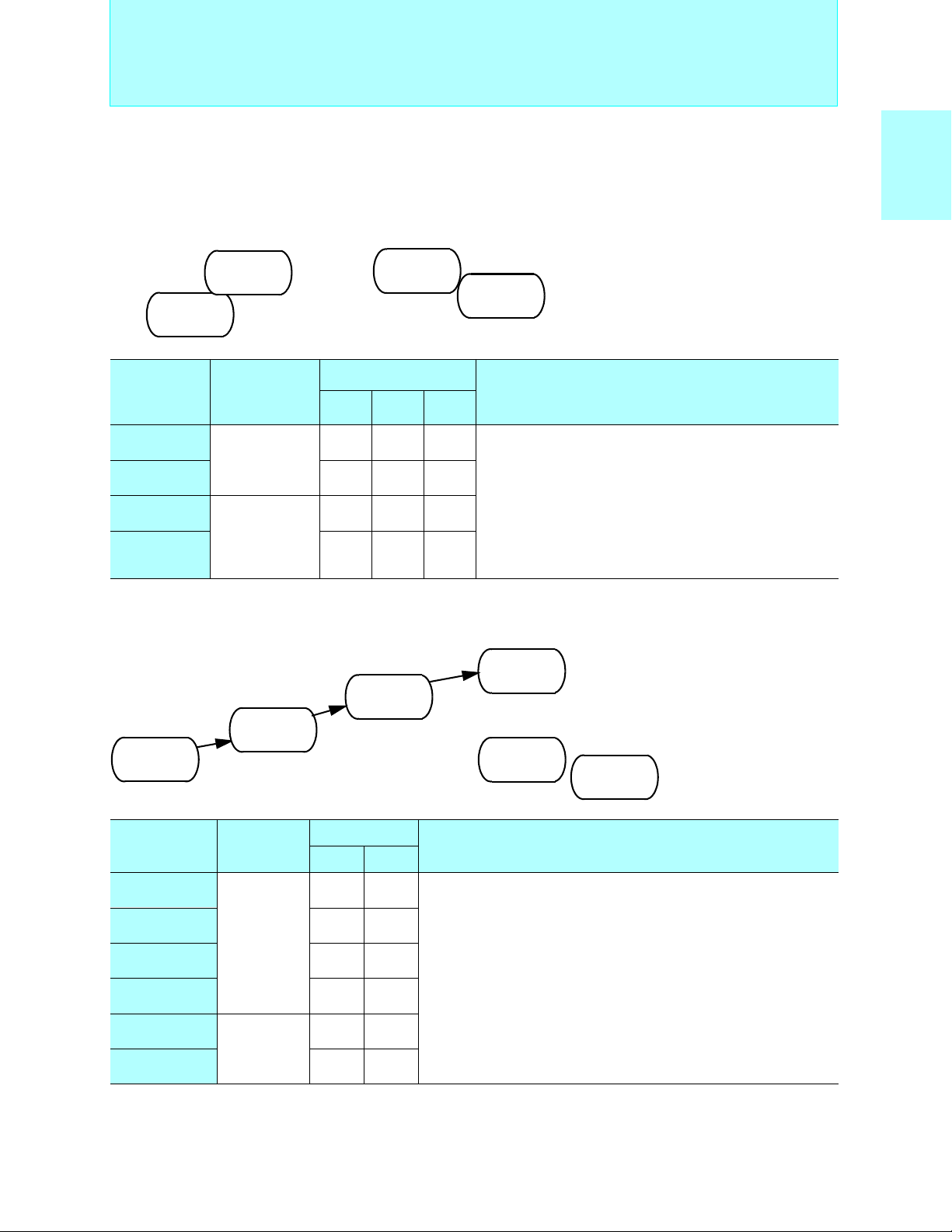
8-bit Proprietary F2MC-8L Family
Internal LCD Controller/Driver Products
MB89800 Series
Standard products (LCD controller/driver)
MB89805
ROM 16KB
RAM 512B
MB89803
ROM 8KB
RAM 256B
Operating
Part number
MB89803
MB89805 100P 100P −
MB89P808
MB89PV800 −−100C
Packages: P - plastic C - ceramic
power supply
voltage (V)
+2.2 to +6.0
+2.7 to +6.0
LQFP QFP MQFP
100P 100P −
100P 100P −
MB89P808
OTPROM 48KB
RAM 1KB
Package
MB89PV800
Ext. ROM
RAM 1KB
<Evaluation device>
I/O ports: 32
Timebase timer (WDT): 21-bit × 1ch.
PWM timer: 8-bit × 1ch.
PWC timer: 8-bit × 1ch.
UART: 1ch.
LCD controller/driver:280 elements, 4 common,
Interrupts: 5 external
Low-power consumption (standby functions) modes: Sleep, stop
MB89650AR Series
Standard products (LCD controller/driver, built-in A/D converter)
MB89657AR
MB89656AR
ROM 24KB
MB89655AR
ROM 16KB
MB89653AR
ROM 8KB
RAM 256B
Part number
MB89653AR
MB89655AR 100P −
MB89656AR 100P −
MB89657AR 100P −
MB89P657A
MB89PV650A − 100C
RAM 512B
Operating
power supply
*
voltage
+2.2 to +6.0
+2.7 to +6.0
(V)
RAM 768B
Package
QFP MQFP
100P −
100P −
MB89P657A
OTPROM 32 KB
I/O ports: 64
Timebase timer (WDT): 21-bit × 1ch.
Timer/counter: 8-bit × 4ch. (16-bit × 2ch.)
PWM timer : 8-bit × 2ch. (4 outputs)
A/D converter: 8-bit × 8ch.
LCD controller/driver: 128 elements, 2 to 4 common,16 to 32 segments,
SIO: 8-bit × 1ch.
Clock prescaler: 15-bit
Buzzer output
Interrupts: 8 internal, 16 external
Low-power consumption (standby functions) modes:Sleep, watch, stop
ROM 32KB
RAM 1KB
RAM 1KB
• Maximum clock frequency: 10 MHz
• Minimum execution time: 0.4 µs/5V
• Operating temperature range:
-40°C to +85°C
Functions
70 segments, 4-bit × 70 LCD display RAM
• Maximum clock frequency:
10 MHz (32.768 kHz)
• Minimum execution time:
0.4 µs to 6.4 µs (61 µs)
• Operating temperature range:
-40°C to +85°C
MB89PV650A
Ext. ROM
RAM 1KB
<Evaluation device>
Functions
4 bias power supplies,
16 × 8-bit LCD display RAM
Booster circuit (selected as an option)
(MB89653AR/655AR/656AR/657AR)
No booster circuit (MB89P657A/PV650A)
MC-8LFamily
2
F
*: A/D = 3.5V to 6.0V
Packages: P - plastic, C - ceramic
49
Page 51

8-bit Proprietary F2MC-8L Family
(Continued)
Main functions
A/D converter
(10-bit × 8ch.),
D/A converter
(8-bit × 2ch.),
UART or SIO,
UART/SIO,
PWM timer
(8-bit × 2ch.),
timer/counter
(8-bit × 2ch.) × 2
(16-bit × 1ch.),
PWC timer
(8-bit × 1ch.),
PPG timer
(6-bit × 1ch.),
LCD controller
(32seg. × 4
com.)
Series
name
MB89550A
series
Type ROM RAM Part number
Mass
production
OTPROM 48 KB 2 KB
Evaluation
device
Internal LCD Controller/Driver Products
32 KB 1 KB MB89557A
48 KB 2 KB MB89558A
Equivalent device
32 KB
(Ext.)
MB89557A
MB89558A
Evaluation target device
2 KB
MB89550A
series
MB89P558A
MB89PV550A
50
Page 52
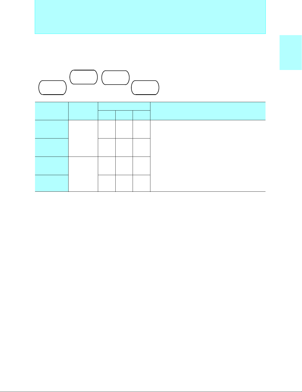
8-bit Proprietary F2MC-8L Family
Internal LCD Controller/Driver Products
MB89550A Series
Standard products (compact camera, etc.)
MB89558A
ROM 48KB
MB89557A
ROM 32KB
RAM 1KB
RAM 2KB
Operating
Part number
power supply
voltage
(V)
MB89557A
+2.2 to +3.6
+2.2 to +5.5
MB89558A 100P 100P −
MB89P558A
+2.7 to +5.5
MB89PV550A −−100C
*1: Power supply for logic at Vcc1
*2: Power supply for I/O at Vcc2
Packages: P - plastic, C - ceramic
MB89P558A
OTPROM 48KB
RAM 2KB
<Evaluation device>
Package
LQFP TQFP MQFP
100P 100P −
*1
*2
100P 100P −
MB89PV550A
• Maximum clock frequency: 12.5 MHz (32.768kHz)
• Minimum execution time: 0.32 µs (61µs)
Ext. ROM
RAM 2KB
• Operating temperature range: -40°C to +85°C
Functions
I/O ports: 66
Timebase timer (WDT): 21-bit × 1ch.
Timer/counter:8-bit×4ch.(16-bit × 2ch.),16-bit×1ch.
PWM timer: 8-bit × 2ch.
PWC timer: 8-bit × 1ch.
PPG timer: 6-bit × 1ch.
A/D converter: 10-bit × 8ch.
D/A converter: 8-bit × 2ch.
LCD controller/driver:128 elements, 2 to 4 common,
UART/SIO: 8-bit × 2ch.
Interrupts: 10 internal, 5 external
Low-power consumption (standby functions) modes: Sleep,
8 to 32 segments,
1/2, 1/3 bias power supplies,
32 × 4-bit LCD display RAM,
booster circuit (selected as an option),
static, duty
watch, sub
MC-8LFamily
2
F
51
Page 53

8-bit Proprietary F2MC-8L Family
VFD Driver Products
F2MC-8L
Family
VFD
Driver
Products
Pin
count
Main functions
High withstand
48
ports,
low voltage
detection circuit,
A/D converter
(8-bit × 8ch.),
SIO,
PWM timer
64 Vacuum fluores-
cent display
driver,
A/D converter
(10-bit × 12ch.),
PWM timer
(8-bit × 1ch.),
MPG timer
(12-bit × 1ch.),
timer/counter
(8-bit × 2ch., can
operate as 16bit),
SIO(8-bit × 1ch.)
Series
name
MB89910
series
MB89140
series
Type ROM RAM Part number
Mass
production
OTPROM 16 KB 512 B
Evaluation
device
Mass
production
OTPROM 32 KB 1 KB
8 KB 256 B MB89913
16 KB 512 B MB89915
Equivalent device
MB89910
series
32 KB
(Ext.)
8 KB 256 B MB89143A
12 KB 256 B MB89144A
16 KB 512 B MB89145
24 KB 768 B MB89146
Evaluation target device
1 KB
MB89910
series
Equivalent device
MB89140
series
MB89P915
MB89PV910
MB89P147
Evaluation
device
32 KB
(Ext.)
Evaluation target device
1 KB
MB89140
series
MB89PV140
52
Page 54

8-bit Proprietary F2MC-8L Family
2
MC-8L Family VFD Driver Products
F
■
MB89910 Series
Standard products (vacuum fluorescent display driver, compact 8-bit microcontroller)
• Maximum clock frequency:
8 MHz (32.768 kHz)
• Minimum execution time:
0.5 µs to 8.0 µs (61 µs)
• Operating temperature range:
-40°C to +85°C
MB89913
ROM 8KB
RAM 256B
MB89915
ROM 16KB
RAM 512B
MB89P915
OTPROM 16KB
RAM 512B
MB89PV910
Ext. ROM
RAM 1KB
<Evaluation device>
VFD Driver Products
MC-8LFamily
2
F
Operating
Part number
MB89913
MB89915 48P 48P −
MB89P915 48P 48P −
MB89PV910 +4.5 to +5.5 −−64C
Packages: P - plastic, C - ceramic
power supply
voltage (V)
+3.8 to +5.5
Package
SDIP QFP MDIP
48P 48P −
Functions
I/O ports: 39
High withstand voltage ports: 8
Timebase timer (WDT): 21-bit × 1ch.
Timer/counter: 16-bit × 1ch.
PWM timer: 8-bit × 1ch.
A/D converter: 8-bit × 8ch.
SIO: 8-bit × 1ch.
Clock prescaler: 15-bit
Low-voltage detection reset (selectable from 4.3V to 3.7V, 3.9V to 3.3V,
or 3.6V to 3.0V)
Interrupts: 6 internal, 2 external
Low-power consumption (standby functions) modes:
Sleep, watch, stop, sub
MB89140 Series
Standard products (vacuum fluorescent display driver, 10-bit A/D converter, built-in inverter macro)
MB89143A
ROM 8KB
RAM 256B
MB89144A
ROM 12KB
RAM 256B
MB89145
ROM 16KB
RAM 512B
MB89146
ROM 24KB
RAM 768B
MB89P147
OTPROM 32KB
RAM 1KB
MB89PV140
Ext. ROM
RAM 1KB
<Evaluation device>
• Maximum clock frequency:
8 MHz (32.768 kHz)
• Minimum execution time:
0.5 µs to 8.0 µs (61 µs)
• Operating temperature range:
-40°C to +85°C
Operating
Part number
MB89143A
MB89144A 64P −− −
MB89145
MB89146 64P 64P −−
MB89P147 64P 64P −−
MB89PV140 −−64C 64C
*: A/D = 3.5V to 6.0V
Packages: P - plastic, C - ceramic
power supply
voltage(V)
+4.0 to +6.0
+2.7 to +6.0 *
SDIP QFP MDIP MQFP
64P −− −
64P 64P −−
Package
I/O ports: 55
High withstand voltage ports: 25
Timebase timer (WDT): 21-bit × 1ch.
Timer/counter: 8-bit × 2ch. (16-bit × 1ch.)
PWM timer: 8-bit × 1ch.(MB89143 except)
MPG timer: 12-bit × 1ch.(MB89143 except)
A/D converter: 10-bit × 12ch.(MB89143: 8-bit × 8ch.)
SIO: 8-bit × 1ch.
Clock prescaler: 15-bit
Buzzer output
Interrupts: 10 internal, 2 external
Low-power consumption (standby functions) modes:
Functions
Sleep, watch, stop, sub
53
Page 55
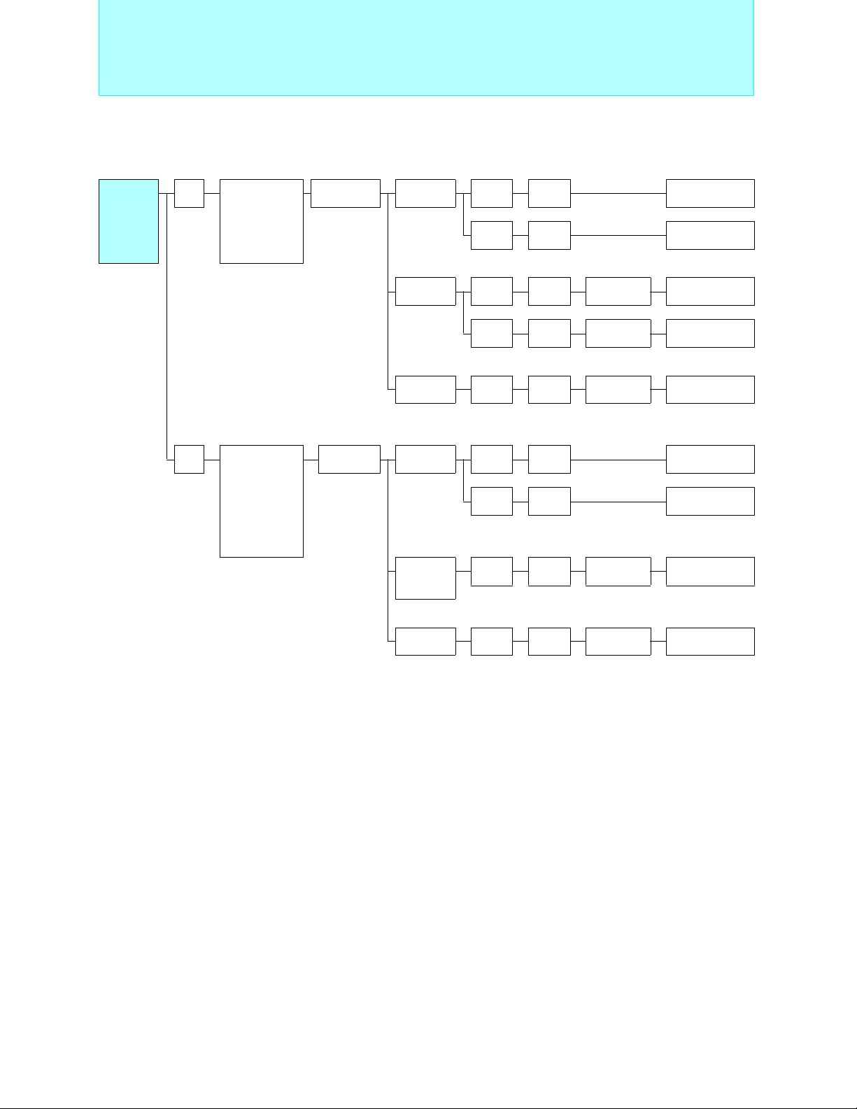
8-bit Proprietary F2MC-8L Family
Internal DTMF Generator Products
F2MC-8L
Family
Internal
DTMF
Generator
Products
Pin
count
48
100
Main
functions
DTMF generator,
timer/counter
(8-bit × 2ch.),
SIO
(8-bit × 1ch.)
DTMF generator,
A/D converter
(8-bit × 8ch.),
SIO,
PWM timer,
software
modem
Series
name
MB89170/A
series
MB89890
series
Type ROM RAM Part number
Mass
production
OTPROM 8 KB 384 B MB89173 MB89P173
Evaluation
device
Mass
production
OTPROM
Evaluation
device
8 KB 384 B MB89173
12 KB 512 B MB89174A
Equivalent device
16 KB 512 B MB89174 MB89P175A
Evaluation target device
32 KB
(Ext.)
48 KB 1.5 KB MB89898
60 KB 2 KB MB89899
60 KB 2 KB
1 KB
MB89170/A
series
Equivalent device
MB89890
series
MB89PV170A
MB89P899
Evaluation
device
60 KB
(Ext.)
Evaluation target device
2 KB
MB89890
series
MB89PV890
54
Page 56
8-bit Proprietary F2MC-8L Family
2
MC-8L Family DTMF Generator Products
F
■
MB89170/170A Series
Standard products (built-in DTMF generator, low cost)
MB89174A
MB89173
ROM 8KB
RAM 384B
MB89P173
OTPROM 8KB
RAM 384B
ROM 12KB
RAM 512B
MB89P175A
OTPROM 16KB
RAM 512B
MB89PV170A
Ext. ROM
RAM 1KB
<Evaluation device>
Internal DTMF Generator Products
• Maximum clock frequency:
3.58 MHz (32.768 kHz):MB89170 series
7.16 MHz (32.768 kHz):MB89170A series
• Minimum execution time: 0.6 µs to 17.6 µs (61 µs)
• Operating temperature range:-40°C to +85°C
MC-8LFamily
2
F
Operating
Part number
MB89173
MB89174A 48P −
MB89P173
MB89P175A 48P −
MB89PV170A − 48C
Packages: P - plastic, C - ceramic
power supply
voltage (V)
+2.2 to +6.0
+2.7 to +6.0
Package
QFP MQFP
48P −
48P −
I/O ports: 37
Timebase timer (WDT): 21-bit × 1ch.
Timer/counter: 8-bit × 2ch. (can also operate as 16-bit × 1ch.)
DTMF generator: All tone output for CCITT
SIO: 8-bit × 1ch.
Clock prescaler: 15-bit
Interrupts: 4 internal,11 external
Low-power consumption (standby functions) modes:Sleep,watch,stop,sub
MB89890 Series
Standard products (DTMF generator, built-in MSK modem 100-pin)
MB89899
ROM 60KB
MB89898
ROM 48KB
RAM 1.5KB
Part number
Operating
power supply
voltage *(V)
Package
QFP MQFP
MB89P899
OTPROM 60KB
RAM 2KB
RAM 2KB
<Evaluation device>
MB89PV890
Ext. ROM
RAM 2KB
Functions
• Maximum clock frequency:
8 MHz (32.768 kHz)
• Minimum execution time:
0.5 µs to 8.0 µs (61 µs)
• Operating temperature range:
-20°C to +85°C
Functions
MB89898
+2.2 to +6.0
MB89899 100P −
MB89P899
+2.7 to +6.0
MB89PV890 − 100C
*: A/D = 3.5V to 6.0V
Packages: P - plastic, C - ceramic
100P −
100P −
I/O ports: 85
Timebase timer (WDT): 21-bit × 1ch.
Timer/counter: 8-bit × 2ch. (can also operate as 16-bit × 1ch.)
PWM timer: 8-bit × 1ch.
A/D converter: 8-bit × 8ch.
DTMF generator: All tone output for CCITT
SIO: 8-bit × 1ch + serial with 1-byte buffer × 1ch.
MSK software modem output: 1200, 2400bps
MSK software modem timer: 1ch. (built-in noise reduction circuit)
Clock prescaler: 15-bit
Buzzer output (7 tones)
Interrupts: 9 internal, 16 external (4 × edge interrupts, 12 × level interrupts)
Low-power consumption (standby functions) modes:Sleep,watch,stop
55
Page 57

8-bit Proprietary F2MC-8L Family
Inverter Motor Control Products
F2MC-8L
Family
Inverter
Motor
Control
Products
Pin
count
64
Main
functions
Inverter motorcontrol,
A/D converter
(10-bit × 8ch.),
PWM timer,
UART,
SIO
Series
name
MB89850/R
series
Type ROM RAM Part number
Mass
production
OTPROM
Evaluation
device
EPROM/
Evaluation
device
16 KB 512 B MB89855
MB89855A
MB89855R
60 KB
(
Ext.)
32 KB 1 KB MB89857
32 KB 1 KB
32 KB
(Ext.)
512 B MB89T855
Equivalent device
MB89850/R
series
Evaluation target device
1 KB
MB89850/R
series
MB89P857
MB89W857
80
Inverter control circuit,
A/D converter
(10-bit × 8ch.),
PWM timer,
UART,
SIO
MB89860
series
Mass
production
OTPROM
Evaluation
device
EPROM
Evaluation
device
16 KB 512 B MB89865
32 KB 1 KB MB89867
Equivalent device
32 KB 1 KB
Evaluation target device
32 KB 1 KB
MB89860
series
MB89860
series
MB89P867
MB89W867
56
Page 58

8-bit Proprietary F2MC-8L Family
2
MC-8L Family Inverter Motor Control Products
F
■
MB89850/850R Series
ASMC (1) (inverter motor control, built-in high-speed pulse output)
MB89857
ROM 32KB
RAM 1KB
MB89W857
EPROM 32KB
RAM 1KB
MB89855/A
ROM 16KB
RAM 512B
MB89855R
ROM 16KB
RAM 512B
MB89T855
ROM Ext.
RAM 512B
MB89P857
OTPROM 32KB
RAM 1KB
<Evaluation device>
Inverter Motor Control Products
• Maximum clock frequency: 10 MHz
• Minimum execution time: 0.4 µs
• Operating temperature range:
-40°C to +85°C
MC-8LFamily
2
F
Operating
Part number
MB89855
MB89855A 64P 64P
MB89855R 64P 64P
MB89T855
MB89857
MB89P857
MB89W857 64C 64C
*1 : A/D = 3.5 V to 6.0 V
*2 : A/D = 3.5 V to 5.5 V
Package: P - plastic, C - ceramic
power supply
+2.7 to +6.0 *
+2.7 to +5.5 *
+2.7 to +6.0 *
+2.7 to +5.5 *
voltage
(V)
Package
SH-DIP QFP
64P −
1
2
64P −
1
64P −
64P 64P
2
I/O ports: 53
Timebase timer (WDT): 20-bit × 1 ch.
PWM timer:8-bit × 2 ch. (with reload timer function)
Timer unit:
10-bit up/down count timer × 1 ch. , output compare register × 4 ch.(with
buffer) (0.4µs min resolution), real time waveform output pins × 7 ch.
Deadtime timer:
4-bit load timers × 3ch. (non-overlap 3-phase waveform output for timer
unit output), includes a function to disable output on detection of over-cur-
rent (edge or level input)
A/D converter: 10-bit × 8 ch.
SIO: 8-bit × 1ch.
UART: 8-bit × 1 ch.
Interrupts: 9 internal, 4 external
Low-power consumption (standby functions) modes: Sleep, stop
MB89860 Series
ASMC (1) (inverter motor control, built-in high-speed pulse output)
MB89867
ROM 32KB
RAM 1KB
MB89W867
MB89865
ROM 16KB
RAM 512B
MB89P867
OTPROM 32KB
RAM 1KB
<Evaluation device>
EPROM 32KB
RAM 1KB
Functions
• Maximum clock frequency: 10 MHz
• Minimum execution time: 0.4 µs
• Operating temperature range:
-40°C to +85°C
Operating power
Part number
MB89865
MB89867 80P
MB89P867
MB89W867 80C
*1 : A/D = 3.5 V to 6.0 V
*2 : A/D = 3.5 V to 5.5 V
Package: P - plastic, C - ceramic
supply voltage
(V)
+2.7 to +6.0 *
+2.7 to +5.5 *
1
2
Package
QFP
80P
80P
Functions
I/O ports:68
Timebase timer (WDT): 20-bit × 1ch.
PWM timer: 8-bit × 2ch. (with reload timer function)
Timer unit:10-bit up/down count timer × 1ch., output compare registers × 4
(with buffer), (0.4µs min. resolution), real time waveform output
pins × 7ch.
Deadtime timer:4-bit load timers × 3ch. (non-overlap 3-phase waveform output
for AC inverter motor control.), includes a function to disable
output on detection of over-current (edge or level input)
A/D converter: 10-bit × 8ch.
SIO: 8-bit × 1ch.
UART: 8-bit × 1ch.
Interrupts: 9 internal, 4 external
Low-power consumption (standby functions) modes:Sleep, stop
57
Page 59
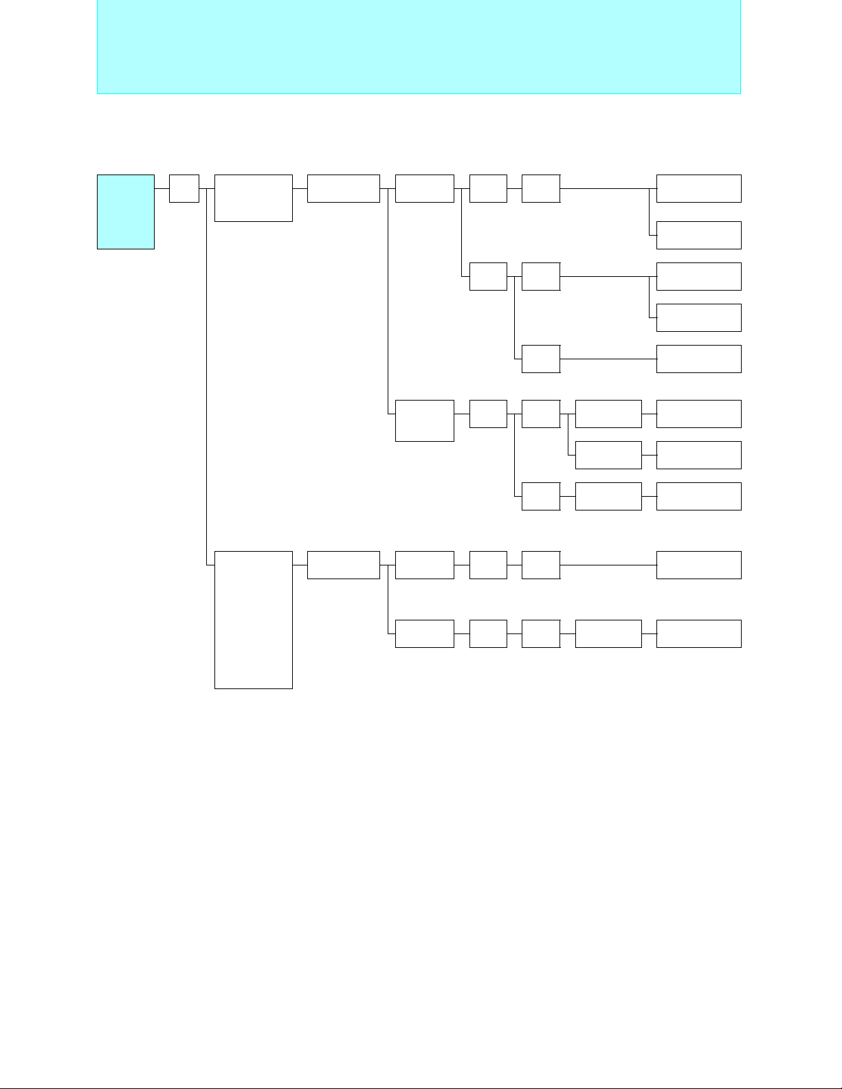
8-bit Proprietary F2MC-8L Family
Internal USB Products
F2MC-8L
Family
Internal
USB
Products
Pin
count
64
Main
functions
USB function,
UART/SIO,
Parallel port,
PWM timer
Series name Type ROM RAM Part number
MB89580B/BW
series
Mass
production
OTPROM
Evaluation
device
8 KB 512 B MB89583B
MB89583BW
16 KB 1 KB MB89585B
MB89585BW
18 KB MB89589B
Equivalent device
16 KB 1 KB
18 KB MB89589B MB89P589B
MB89580B
series
MB89580B
W series
MB89P585B
MB89P585BW
USB function,
UART/SIO
(1 ch. ) ,
external interrupts (7 ch.)
PWM timer
2
I
C bus interface (1 ch.)
clock output
MB89051
series
Mass
production
FLASH 32 KB 2 KB MB89051 MB89F051
32 KB 2 KB MB89051 *
FLASH
ROM
Equivalent
device
* : Under development
58
Page 60

8-bit Proprietary F2MC-8L Family
C
2
MC-8L Family Internal USB Products
F
■
Internal USB Products
MB89580B/580BW Series
Standard products (Internal USB function)
MB89589B
OTPROM 16KB
MB89585B/BW
ROM 16KB
MB89583B/BW
ROM 8KB
RAM 512B
RAM 1KB
Operating
Part number
power supply
voltage (V)
MB89583B
MB89583BW 64P −
MB89585B 64P −
MB89585BW 64P −
MB89589B − 64P
MB89P585B 64P −
MB89P585BW 64P −
MB89P589B − 64P
Package : P - plastic
+3.0 to +5.5
RAM 18KB
MB89P585B/BW
OTPROM 16KB
RAM 1KB
<Evaluation device>
Package
LQFP
(0.5 mm
pitch)
64P −
LQFP
(0.65 mm
pitch)
• Maximum clock frequency: 12 MHz
• Minimum execution time: 0.33 µs
• Operating temperature range:-40°C to +85°
MB89P589B
OTPROM 16KB
RAM 18KB
Functions
I/O ports : 53
Timebase timer : 21-bit × 1ch.
PWM timer : 8-bit × 2ch. (also used as PPG timer × 1ch.)
USB function
UART/SIO : 1ch.
Parallel port
State of terminal RPVP(D+) and RPVM(D−) until starting USB
connection :
Interrupts : 8 external
Low-power consumption (standby functions) modes : Sleep, stop
High-Z : MB89593B/595B/P595B
Low-level output : : MB89593BW/595BW/P595BW
MC-8LFamily
2
F
MB89051 Series
Standard products (Internal USB function)
MB89051
ROM 32 KB
RAM 2 KB
Under development
Part number
MB89051
MB89F051
Package : P - plastic
: Under development
Operating
power supply
voltage (V)
+3.0 to +5.5
FLASH ROM 32 KB
<Evaluation device>
Package
MB89F051
RAM 2 KB
LQFP
64P
64P
• Maximum clock frequency: 12 MHz
• Minimum execution time: 0.33 µs
• Operating temperature range:-40°C to +85°C
(USB operation : 0°C to +70°C)
Functions
I/O ports: 41
USB function (endpoint : 4)
Timebase timer : 21-bit × 1 ch.
PWM timer : 8-bit × 2 ch.
UART/SIO : 1 ch.
Interrupts: 7 external
2
I
C bus interface (1 ch.)
Clock output : 6 MHz, 12 MHz
Low-power consumption (standby functions) modes: Sleep, stop
59
Page 61

8-bit Proprietary F2MC-8L Family
Environment Development Features
■
(1)Development efficiency enhancemen t
• Provides integrated total environment
S
OFTUNE V3 Workbench (Manager + Debugger)
OFTUNE V3 Workbench (Manager + Debugger) integrates language tools and debugger tools, further facilitating
S
the repeated process of coding, compiling and debugging.
• High programming efficiency
C compiler support
Structured assembly language support
• High programming development efficiency
Provides C library
Supports C language and assembly source debugging function
• Easy operation by multi windows
OFTUNE V3 Workbench (manager + debugger)
S
SOFTUNE V3 C checker
OFTUNE V3 C analyzer
S
Support Tools
(2) Efficient system development tools
• Provides realtime debugging using real target board
Evaluation tool + S
• Provides software debugging without target board
(3) Total development environment
• Personal computer (IBM-PC)
• ICE tool (MB2140A series, personal emulator)
(4) Conformity with standards
Improves versatility and portability of software resources
• C language: Conforms to ANSI standard
• C library: Conforms to ANSI standard
OFTUNE V3 Workbench emulator debugger
60
Page 62

8-bit Proprietary F2MC-8L Family
Support Tools
■ SOFTUNE
V3
1. The SOFTUNE Integrated Development Environment
Function/Integration Level
Individual tools
MS-DOS/UNIX
SOFTUNE V1
Windows3.1version
Development
manager
debugger
C checker
C analyzer
REALOS configurator
(Tool inter-operation)
C compiler
Assembrer
Linker
Simulator debugger/Emulatordebbuger
Combines and integrates tools
S
OFTUNE V3
WindowsXP/Me/2000/98/NT
SOFTUNE Workbench
S
OFTUNE C compiler
OFTUNE assembler
S
OFTUNE linker
S
S
OFTUNE REALOS
OFTUNE C checker
S
OFTUNE C analyzer
S
- Integrates the development manager
and debugger
- 32-bit operation improves processing
speed
- Enhanced REALOS support
- Language specifications,OMF integration
Improved management of
software assets Accumulate and
disseminate practical knowhow
2. SOFTUNE V3 Features and Structure
Workbench integrated project manager and two debugger modules
Errors can be corrected on the "fly", as they are discovered, and the resulting code can be debugged on the spot.
A variety of tools to support C-language coding are available
"C Checker" confirms code operation and "C Analyzer" analyzes the code’s structure.
MC-8LFamily
2
Support tools
F
(1) Removing the Annoying Settings which are Part of Program Development
Developing programs for different systems requires the programmer to edit source code, perform actual builds
and confirm program operations (debug). Finally, the programmer returns to the editing process to incorporate
necessary changes, as indicated by debugging results.
OFTUNE V3 is an integrated developing environment which is designed to perform such repetitive processes
S
smoothly and efficiently. It is the third generation of SOFTUNE, which has evolved to meet various needs of our
customers.
(2) Program Flow
Editing
Error correction
Building
Debugging
61
Page 63
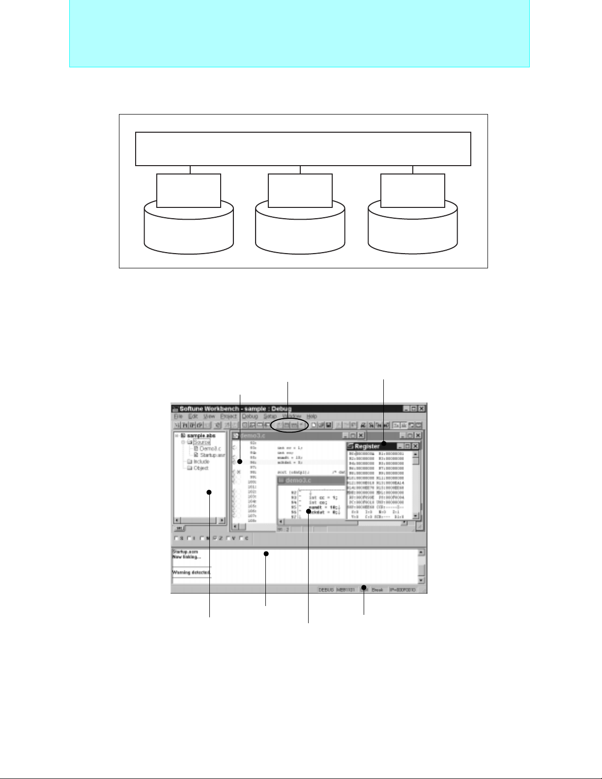
8-bit Proprietary F2MC-8L Family
(3) Structure of SOFTUNE V3
OFTUNE V3 Workbench (Development Manager/Debugger)
• S
Support Tools
(4) Environment with S
SOFTUNE V3
Ianguage
tool
• C Compiler
• Assembler
• Linkage Kit
OFTUNE V3
SOFTUNE V3
cooperation
• C Checker
• C Analyzer
SOFTUNE V3
REALOS
• Kernel
• Configurator
The Efficient and Easy-to-Use Integrated Developing Environment.
Program development requires repeated editing, make/build, and debugging operations. Performing these functions
smoothly and effectively contributes to improved efficiency.
The S
OFTUNE V3 integrated developing system is designed to meet program developers’ numerous demands, while
ensuring ease of use.
Make/build
Register window
Source window
62
Project window
Output window
Tool display
Editing window
Page 64
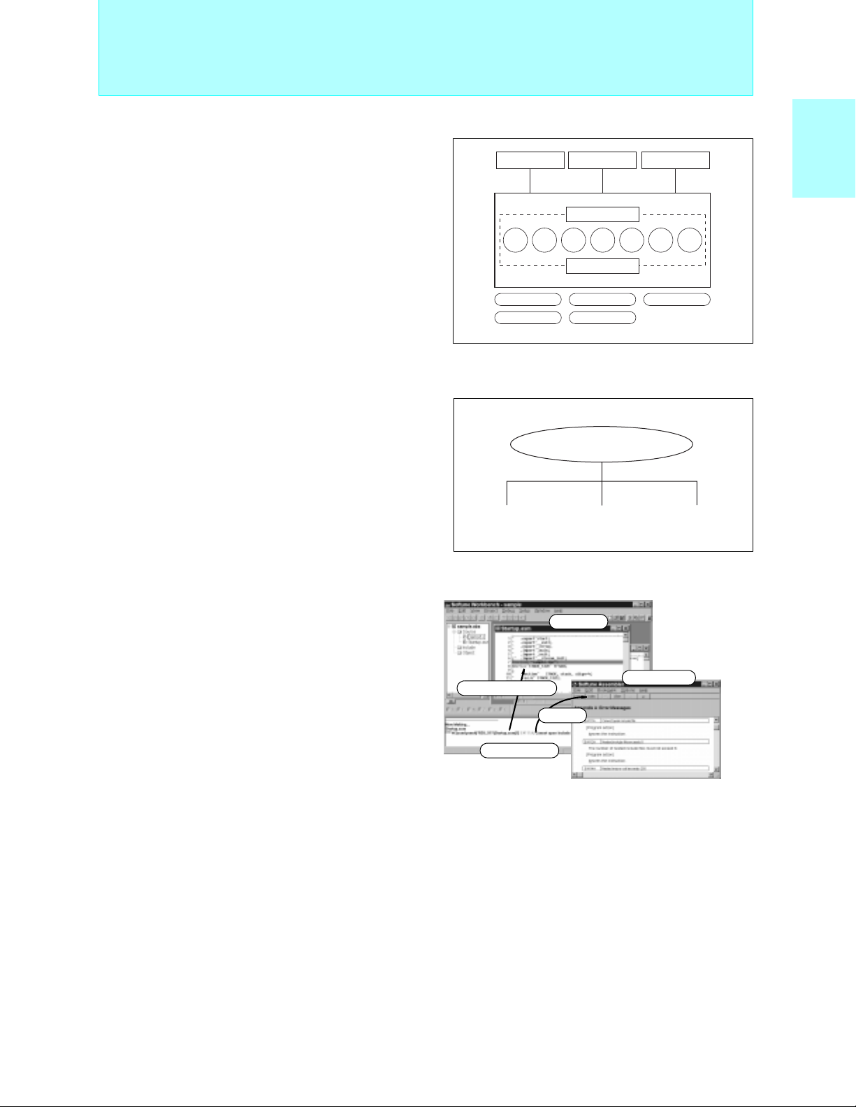
8-bit Proprietary F2MC-8L Family
Support Tools
3. Manager Functions
Software programming proceeds according to the
“project file”, which contains all the information needed for program development.
(1) Effective Project Usage
Whether working alone on several projects simultaneously or
developing a project as a group, project files can be used to
create a simple developing environment.
Coding
Source Source Source
Editor Assembler/Linker
Emulator
Building
OFTUNE Workbench
S
Project
OBJ OBJ OBJ
Option
Compiler
Simulator
Debugging
LM
Common project file
Operator A Operator B Operator C
MC-8LFamily
2
Support tools
F
(2) Extremely Easy to Use
• Built-in Editor
The built-in editor comes complete with many useful
Edit window
functions, such as visual keyword emphasis and autoindent.
• Error Jump and On-line Help
Errors that occur during builds are displayed in the
output window at the bottom of the screen.
To make a "Tag-jump" Double-click Mouse.Once on
Mouse double-click
F1 key
Detailed help
the error press "F1 key" for a more detailed error
display.
Compile error
• Cooperation with Commercially Available Editors
To meet developers’ requests to use edito rs t o which
they are accustomed, S
OFTUNE can be configured to use the following commercially available
editors:(Codewright32, TextPAD32 and others)
(3) Customizable Environment
When sharing files, cooperation with source generation management tools is assured, and file type conversion tools
are called up, so that each person can operate in his or her own customized developing environment.
63
Page 65

8-bit Proprietary F2MC-8L Family
Support Tools
4. Debugger Function
SOFTUNE Workbench supports two debuggers that are needed at various stages of development. The appropriate
debugger environment can be selected to match the situation.
SOFTUNE Workbench
Emulator
debugger
RS232C/LAN
ICE
Simulator
debugger
Memory
Instruction
simulator
(1) Easy-to see Screen Information
The user can freely change the screen layout by selecting the necessary windows. In addition, the displayed information can be selected to provide only the infomation that is necessary.
Soruce window
Project window
Memory window
Watch window
Register window
(2) Simple Environment Setting
• Debugging Environment: Setup "Wizard"
The setup "wizard" supports the selection of communication lines with emulation pods and boards, as well as
window settings.
• MCU Operating Environment
The so-called “CPU information file,” which contains the information required to support all MCUs, is provided
as standard. Necessary information such as I/O port locations, ROM/RAM capacity and initial addresses can be
set automatically.
• Saving and Restoring the Debugging Environment
Previous debugging environment specification, such as window locations, breakpoint settings, and me mory
mapping information, are saved, so that these settings are restored the next time the program is initiated.
64
Page 66

8-bit Proprietary F2MC-8L Family
Support Tools
5. Cooperation
In cooperation with SOFTUNE Workbench, the following SOFTUNE components help improve the quality of C-language
programming, which greatly increases reviewing and documentation efficiency.
1)SOFTUNE V3 C Checker
Designed to meet the following requests from beginners through to advanced users:
• Eliminate all coding mistakes.
• Review programs quickly and efficiently.
• Enable even C-language beginners to create quality code.
• Maximize coding skills.
• Use software assets on Fujitsu CPUs.
OFTUNE C Checker checks code for maintainability, methods of expanding specifications and transportability;
The S
indicates areas where quality and performance could be improved, and reports these results to the user. The user
can then review the C-language code.
(1) Outline
Recently software for embedded microcontrollers has been developed in the C language. However, it is difficult to
understand the message output from a compiler unless the language specifications are well known.
This development support tool checks C-source programs to display and print advice for better quality and
performance. It also has a facility for selecting necessary advice carefully.
(2) Features
• Outputs advised to be suitable for these objectives: Portability, coding errorperformance, porting to Fujitsu
CPU’s.
• Allows customization according to the programmers level.
• Works with C compilers (fcc911/fcc911s, cc907/fcc907s, fcc896s) for Fujitsu microcontrollers (FR family, F2MC16 family, and F
• Provides easy operation and simple display over a GUI.
2
MC-8L family).
MC-8LFamily
2
Support tools
F
(3) Advising Function
The following pieces of advice are given. “Reason of check”, “Example of program”, “Suggestion of correction”, and
“One-point advice” are displayed and explained for each check item.
• Portability
This tool makes a close check on the items “processing-definded operation” and “undefined operation” which can
be problems in portability within the ANSI standard.
It also gives an explanation of the operation of C compilers (Fcc911, Fcc907 and Fcc896) for Fujitsu microcontrollers.
For example, the tool gives the user proper advice on many problems (such as a data type acceptable to a
structure, code, and its arrangement) at the time of porting.
• Coding error
This tool indicates the items which are not wrong in the language specifications but may cause an error and the
items which are logically inconsistent.
For example, the equivalent expression "if (a==0)" in the if statement is likely to be typed as the assignment
expression "if (a=0)" by mistake. Most compilers cannot detect such an error.
• Performance
This tool indicates the items generally providing better performance and the items essential and effective for the
2
FR family, F
MC-16 family and F2MC-8L family.
Stress is especially, put on the detection of object size reduction which can be a problem in software for
embedded microcontrollers.
For example, if a function return value is structure of the double type, an area is reserved for the return value and
an object which is to be transferred to the area is output.
This tool advises the user to transfer the function return value by a pointer and largely reduce the object size.
• Porting to Fujitsu CPU
This tool advises the user what to consider in porting exsting software from other makers’ CPU to Fujitsu CPU in
2
the FR family, F
For example, in porting software resources created for the F
MC-16 family and F2MC-8L family.
2
MC-16 family to the FR family, this tool advises the
user to delete the expansion specifications (__far, __near, and __direct etc.) inherent to the F2MC16 family.
65
Page 67
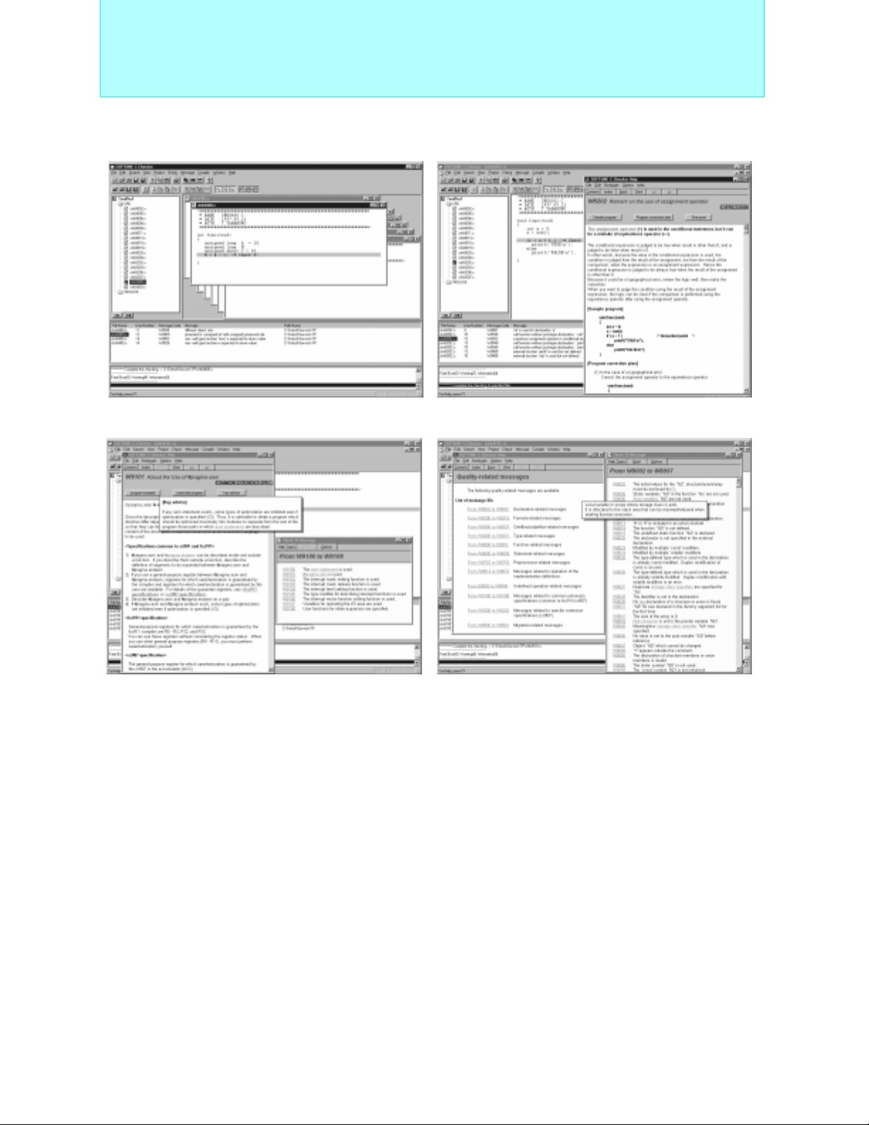
8-bit Proprietary F2MC-8L Family
•Indicated messages output • Coding error indicated and advice displayed
• Advice of porting to Fujitsu C compilers displayed • Quality-related massages listed
Support Tools
66
Page 68

8-bit Proprietary F2MC-8L Family
Support Tools
2) SOFTUNE V3 C Analyzer
Designed to meet the following user situations:
• One wishes to examine a program’s structure or processing, but the programmer is absent or documentation is
unavailable.
• During program development, one wishes to create a structural program while taking into account structure and
processing.
• One wishes to examine the range of effects caused by program modification.
• One wishes to create a program’s internal docu mentation.
• One wishes to explore the possibilities of a more efficient program.
The structure and usage of data in a C-language source program are displayed visually, and the internal data structure, functional tree, stack usage and other infomation can be acquired and stored in a file.
(1) Outline
Recent software (ROM) for embedded microcontrollers is increasingly extending its development scale. This situation
is created from development by many programmers, diversion of exsting resources, and use of package programs.
This development support tool statically analyzes the C-source program to visually display and print the function-tofunction structure, reference data, and statistical data. In addition to generating the information required for design and
maintenance, the development support tool also provides functions for development aimed at embedded applications.
These functions (maximum stack size calculation) are specific to the C compilers (fcc911s, fcc907s, fcc896s) used for
Fujitsu microcontrollers (FR family, F
2
MC-16 family, and F2MC-8L family).
MC-8LFamily
2
Support tools
F
(2) Features
• Displays and prints the function-to-function structure, reference data, and statistical data.
• Supports the embedded capability of C compilers (fcc911/fcc9 11s, cc907/fcc907s, and fcc 896s)for Fujitsu
microcontrollers (FR family, F2MC-16 family and F2MC-8L family).
• Provides easy operation and simple disp lay over a GUI.
(3) Explanation of Features
The following data is enabled for development, maintenance, and higher porting efficiency.
• Graphic flow
This feature displays the "call" function in the block structure way. It also allows the display of the entire function
and calls from any function and the retrieval of functions.
• Logic flow
This feature visually displays the internal structure of the C-source program.
For example, it shapes the control structure of for and switch statements and structure declarations. A jump
feature for retrieval by functions, variable, tag, and macro names is also provided.
• Displaying statistical data
This feature displays the complexity and line count of a programs every function, the source of destination func-
tion name, and the count of appearances of if, for and asm statements, etc.
• Displaying argument data
This feature displays data about the function-called file name and line number, the return value of the declared
function, and the type of argument. It also checks the adjustability of dummy arguments with actual arguments.
• Displaying cross-reference data
This feature displays functions, variables, tag and macro declarations in its function and its line number.
• Displaying global data
This feature displays the functions using global variables. It also detects unused global variables.
• Program checking
This feature checks and displays the adjustabiltiy of dummy arguments with actual arguments.
• Calculating the maximum amount of sta c ks used
This feature calculates and displays the amount of stacks used in the entire function, as well as in any other func-
tions. This calculation is made on the basis of the output of C compilers (fcc911/fcc911s, fcc907/fcc907s, and
fcc896s) for Fujitsu microcontrollers (FR family, F
2
MC-16 family and F2MC-8L family).
67
Page 69
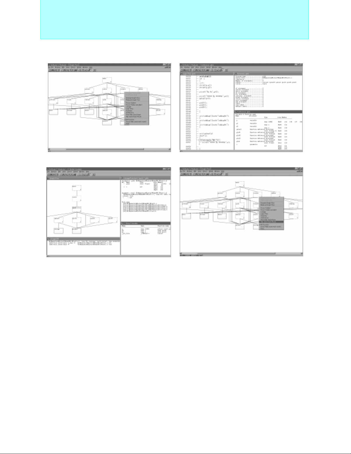
8-bit Proprietary F2MC-8L Family
•Displaying graphic flow • Display i n g l o g i c flow, s t a t i s t i c a l a nd cro s s - r e f e r e n ce dat a
• Displaying logic flow (focus), argument and • Displays stack use volume (green numbers) and
global data largest stack configuration (orange numbers)
Support Tools
68
Page 70

8-bit Proprietary F2MC-8L Family
Support Tools
OFTUNE
■ S
SOFTUNE V3 Professional Pack SP3603Z008-P01
PackProducts
SOFTUNE V3 workbench SP3603W008-P01
SOFTUNE V3 C compiler SP3603C008-P01 ANSI standard conforming
SOFTUNE V3 assembler pack SP3603K008-P01 Assembler, linker, librarian,Object format converter
SOFTUNE V3 analyzer SP3691X008-P01
Individual Products
SOFTUNE V3 C checker SP3691Y008-P01
Compatible emulator hardware (ICE)
2
Operating machine
Operating OS
Personal computers *
Media
*1:The product code suffix (Pxx) indicates the number of licenses.
*2:Pentium or higher CPU recommended. 64MB or more memory recommended. 180MB of a disk capacity is required.
The part number is an ordered number of the newest version.
*3:An electronic manual (PDF format) is provided with each product (Japanese and English).
Printed manuals are sold separately. Licensing of each product is available in a number of forms (3, 5 or 10 copies).
V3 Support Software Product List (F2MC-8L Family)
Software Part number *
MB2140 series
- MB2141A/B
- MB2144-505/508
FMV and similar
IBM compatibles
WindowsXP
WindowsMe
Windows2000
Windows98
WindowsNT4.0
CD-ROM *
3
1
S
OFTUNE V3 workbench
S
OFTUNE V3 C compiler
S
OFTUNE V3 assembler pack
S
OFTUNE V3 analyser
S
OFTUNE V3 checker
Integrated Manager,Simulator debugger and
Emulator debugger functions
For the FR, F
For the FR, F
Remarks
2
MC-16, and F2MC-8L
2
MC-16, and F2MC-8L
−
−
−
−
MC-8LFamily
2
Support tools
F
69
Page 71
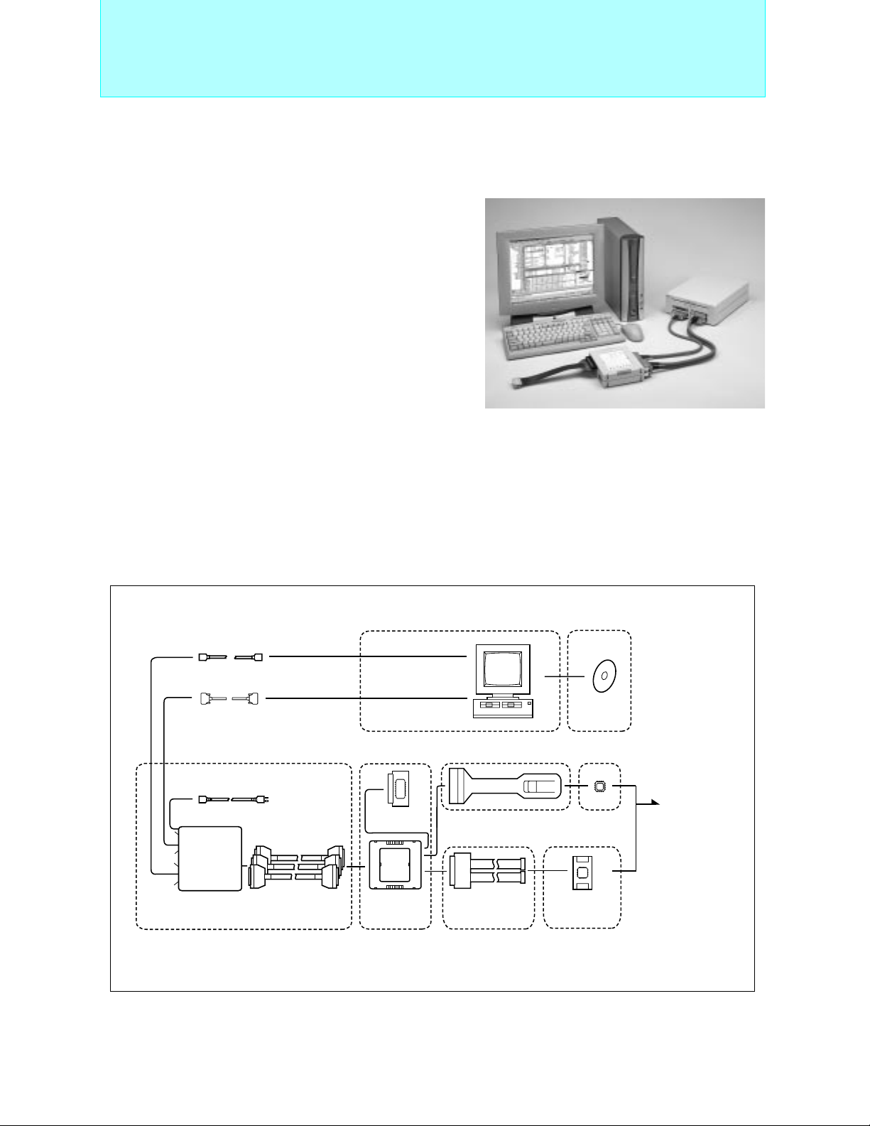
8-bit Proprietary F2MC-8L Family
Support Tools
Support Hardware and F
■
MB2140 Series
2
MC-8L Family Evaluation Tools
System Overview
• Microcontroller operating voltage : +2.7V to +5.5V
The range (Max. and Min.) of Microcontroller operating voltage and
operating freqency depend on each Microcontroller.
See the document including Data Sheet and check the range of
Microcontroller operating voltage and operating freqency.
• Supports debugging of source level (in assembly,
C languages, a mixed indicaton)
• Simplified GUI operation using pull-down menu and
buttons
• On-The-FLY function (commands can be run during
microcontroller execution and reference memory)
• Powerful real time trace function
• Displays source codes, variables, register, memory and
trace on multi windows
• Event trigger allows a wide range of conditions to be
specified (× 8)
• Sequential control in 8 conditions and 8 levels
• Performance measurement function (measurement of execution speed between two points, iteration count
measurement)
0 coverage measurement function (program execution coverage rate measurement)
•C
• Host I/F (standard accessories) : RS-232C (max 115 Kbps) , LAN (10BASE-T)
System configuration
LAN cable (10BASE-T)
RS-232C cable(9pin-9pin cross)
AC cable
Main unit
MB2141B
Main unit
I/F cable
A/B/C
Target
Emulation pod
MB2144-508
Emulatuon pod
Personal computer
For piggyback evaluation
MB2144-20x
Piggyback evaluation
prove cable
For OTP
MB2144-210A
or
MB2144-220
One-time evaluation
probe cable
Emulator/
debbugger
software
S
OFTUNE
workbench
Piggyback
evaluation
device
OTP evaluation
device
MB2144-2xx
Probe header
Connection to
user's system
70
Page 72
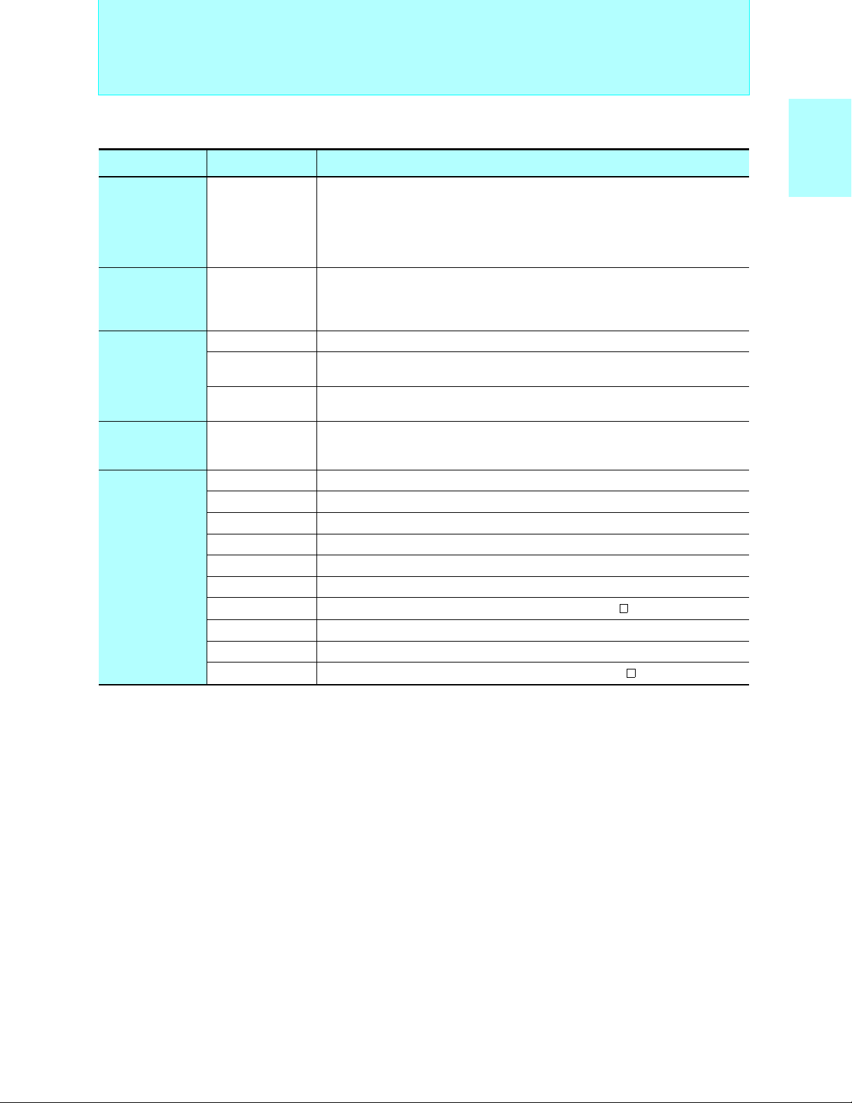
8-bit Proprietary F2MC-8L Family
Support Tools
Name Part number Remarks
For the F
Power supply voltage : 100 V or 200 V.
Main unit MB2141B
Host I/F : RS-232C(115 Kbps) ) , LAN (10BASE-T)
Dimensions : W210 × D297 × H77 mm
Weight : 2.9 kg
Includes : manual
For the F
Emulation pod *
6
MB2144-508
Dimensions :158mm(with) × 126mm(depth) × 38mm(height),
Weight : 0.5kg
Includes : simple target (MB89T625) , manual
MB2144-201 For DIP-28, piggyback/evaluation package: MDIP-64C-P02
Piggyback/evaluation (PV) probe
cable
One-time evaluation probe cable
One-time evaluation probe header
MB2144-202
MB2144-203
MB2144-210A
or
MB2144-220
MB2144-211-01A *
MB2144-212-01A *
MB2144-214-01A *
MB2144-215-01 *
MB2144-216-01 *
MB2144-217-01 *
MB2144-218-01 *
MB2144-224-01 *
MB2144-225-01 *
MB2144-226-01 *
For LCC-32 rectangular, piggyback/evaluation package: MQP-64C-P01,
MQP-80C-P01, MQP-100C-P02
For LCC-32 square, piggyback/evaluation package: MQP-48C-P01,
MQP-100C-P02
Use in conjunction with the probe header for each product type.
1
For the MB89860 series (QFP-80), standard options are mounted on MB89P867
3
For the MB89850 series (SH-DIP-64), standard options are mounted on MB89P857
2
For the MB89810A series (QFP-64), default options are mounted on MB89P817A
2
For the MB89660 series (QFP-64), default options are mounted on MB89P665
3
For the MB89660 series (SH-DIP-64), default options are mounted on MB89P665
4
For the MB89P585B (LQFP-64), default options are mounted on MB89P585B
5
For the MB89R905 (QFP-48) ,FPT-48P-M16 (0.8 mm pitch, 12 × 12 mm)
7
For the MB89P589B (LQFP-64), default options are mounted on MB89P589B
4
For the MB89P585BW (LQFP-64) , default options are mounted on MB89P585BW
8
For the MB89R907A (QFP-48), FPT-48P-M13 (0.8 mm pitch, 10 × 10 mm)
*1 : Includes one Q-pack for QFP-80 (model : TQPACK080RA: made by Tokyo Eletech Ltd.)
Note : Care is required in printed circuit board pattern design because the position of the board connector part (the flat section
at the pin tips) of the Q-pack differs from the mass production product package (the Q-pack pins are shifted a few millimeters inwards).
Includes one Q-socket for QFP-80 (model : TQSOCKET080RAG: made by Tokyo Eletech Ltd.)
2
MC-8L family
2
MC-8L family
MC-8LFamily
2
Support tools
F
*2 : Includes one Q-pack for QFP-64 (model : TQPACK064RZ: made by Tokyo Eletech Ltd.)
Note : Care is required in printed circuit board pattern design because the position of the board connector part (the flat section
at the pin tips) of the Q-pack differs from the mass production product package (the Q-pack pins are shifted a few millimeters inwards).
Includes one Q-socket for QFP-64 (model : TQSOCKET064RZG: made by Tokyo Eletech Ltd.)
*3 : Includes one IC socket for SH-DIP-64 (model : IC83-64075-GS4: made by Yamaichi Electronics Inc.)
*4 : Includes one Q-pack for LQFP-64 (model : TQPACK064SD : made by Tokyo Eletech Ltd.)
Note : Care is required in printed circuit board pattern design because the size of the foot pattern of the Q-pack differs from the
mass production product package (the Q-pack pins are shifted a few millimeters inwards).
Includes one Q-socket for LQFP-64 (model : TQSOCKET064SDW : made by Tokyo Eletech Ltd.)
*5 : Includes one Q-pack for QFP-64 (model : TQPACK064SA : made by Tokyo Eletech Ltd.)
Includes one Q-socket for QFP-64 (model : TQSOCKET064SAW : made by Tokyo Eletech Ltd.)
Note : Care is required in printed circuit board pattern design because the size of the foot pattern of the Q-pack differs from
the mass production product package (the Q-pack pins are shifted a few millimeters inwards).
*6 : Interchangeability to MB2114-505.
71
Page 73

8-bit Proprietary F2MC-8L Family
*7 : Includes one NQ-pack for LQFP-64 (model : NQPACK064SB : made by Tokyo Eletech Ltd.)
Includes one HQ-pack for LQFP-64 (model : HQPACK064SB140 : made by Tokyo Eletech Ltd.)
Note : Care is required in printed circuit board pattern design because the size of the foot pattern of the Q-pack differs from
the mass production product package (the Q-pack pins are shifted a few millimeters inwards).
*8 : Includes a pair of Q-pack and Q-socket for QFP-48 (model: TQPACK048SA, TQSOCKET048SAW: by Tokyo Eletech Ltd.)
Note: The dimension of foot patterns is somewhat different between Q-pack and mass production IC packages.
Be careful in designing patterns of print-circuit boad.
Contact for details:
*1, *2, *4, *5, *7,*8
•USA: Daimaru New York Co. TEL(212)575-0820/0821
OESS Co. Head Office TEL(201)288-4422
OESS Co. Los Angeles Office TEL(714)220-1878
OESS Co. San Jose Office TEL(408)441-1855
•Europe Germany: OESS GmbH TEL(06106)75013
•Asia Hong Kong: Daimaru Kogyo, Ltd. Hong Kong Office TEL(852)8939457/8939108
Singapore: Daimaru Kogyo, Ltd. Singapore Office TEL(65)2251636
*3
•USA: Yamaichi Electronics Inc. TEL(408)4520797
•Europe Denmark : Elmatok A.S. TEL(65)351446
England : Radiatron Components Ltd. TEL(01)8911221
AB Connector Ltd. TEL(0604)712000
Finland : Dualtek Oy TEL(80)8019911
France : Manudax-France TEL(1)4342-2050
Germany: Macrotron AG TEL(089)4208148
Glyn GmbH TEL(49)61278077
Connector Service GmbH TEL(089)429277
Italy : Eurosab International s.r.l TEL(02)93169781
Spain : S.A Generalde Imporciones Electronicas TEL(1)416-92-61
Sweden : Bexab Electronics TEL(08)7680560
Switzerland : Slcovend AG TEL(01)8303161
•Asia Singapore : Yamco Electronics Pte Ltd. TEL(336)6522
Korea : Asia Yamaichi Electronics, Inc. TEL(02)482-7263
Taiwan : Sing Way Co. TEL(02)718-5971
Joung Lai Trading Co. Ltd. TEL(02)754-1022
Support Tools
•Select the probe cable to match the microcontroller being evaluated.
•Use this evaluation tool by connecting to the user system or to the evaluation device on the user system.
•When using a piggyback/evaluation (PV) device, obtain the piggyback/evaluation (PV) device separately.
•A one-time evaluation or EPROM evaluation type evaluation device is mounted in the one-time evaluation or EPROM evaluation
probe cable.
72
Page 74

8-bit Proprietary F2MC-8L Family
Support Tools
Emulator specification for F2MC-8L
Emulator series MB2140 series emulator
Main unit Main unit : MB2141B
Pod MB2144-508 MB2144-505
Target microcontroller
Evaluation device
Operating power supply voltage of micro-
controller *
Operating frequency of microcontroller *
Debugger / OS
Simple target Attachment (MB89T625) No
Memory area
User's memory area
Emulation area
Mirror area : It is used at on-the-fly. It is 5 area in all about copy area of user’s memory area and emulation memory area.
Execution control
Break
Trace capacity
Trace data
Display form oftrace data - Machine cycle - Instruction mnemonic - Sauce line
Event trigger condition setup
Old Yes Yes
New Yes No
Internal : 32 kHz to 20 MHz
External : 8 kHz to 5 MHz
S
OFTUNE V3 Workbench
WindowsXP/Me/2000/98/NT4.0
- User’s memory area
- Emulation memory area
- Undefined area
- Max 20 area
- Unrestricted of area size
- READ, WRITE : an access attribute setup is possible.
Size 64 Kbyte
Mapping unit 1 byte unit, 20area
Access attribute READ, WRITE, GUARD, NOGUARD
- Continuous execution- The automatic change by sauce display
- Step execution- 1 step execution of a sub routine and a function
- Machine language command unit- Permission/prohibition of interrupt
- C language sauce line unit- Permission/prohibition of a watch dog reset function
- Instruction execution break : 64 K point
- Data access break : 64 K point
- Sequential end break
- Garded access break
- Trace buffer full break
- Performance buffer full break
- Forced break
- Single trace : 32 K cycles
(ON/OFF of trace by the event trigger and the sequencer is possible.)
- Multi trace : 2 K blocks
(1 block is 8 cycles before and after an event trigger.)
- Address
- Data
- Status
- External probe data
- The execution level of a sequencer
The number of points 8
Trigger conditions
Sequential level 8
Trigger path Max 16M time
- The AND conditions of address, data, external probe and status.
- All conditions can be specified of don’t care per 1 bit.
F2MC-8L F2MC-8L
2.7 to 5.5 V 2.7 to 5.5 V
Internal : 32 kHz to 16 MHz
External : 8 kHz to 4 MHz
SOFTUNE V3 Workbench
WindowsXP/Me/2000/98/NT4.0
Access status : READ, WRITE, CODE
Inside status of a device : reset, a hold, and data are effective/invalid.
(Continued)
MC-8LFamily
2
Support tools
F
73
Page 75

8-bit Proprietary F2MC-8L Family
(Continued)
Emulator series MB2140 series emulator
Main unit Main unit : MB2141B
Pod MB2144-508 MB2144-505
Support Tools
Target microcontroller
On-the-fly function (Command execution
at the MCU operation)
- Performance measurement function : 4 domains
- Measurement domain : event trigger condition setting domain
Execution time measurement
Co coverage (Rate measurement of program execution complete coverage)
Host computer Personal computer
Host interface
Dimensions, weight
(A projection part and a
cable part remove.)
Power supply for emulator : MB2141B AC 100-120 V and AC 200-220 V are switched automatically.
* : The range (Max. and Min.) of Microcontroller operating voltage and operating freqency depend on each Microcontroller.
See the document including Data Sheet and check the range of Microcontroller operating voltage and operating freqency.
Main unit W210 × D297 × H78 mm, 2.9 kg
Pod W160 × D128 × H40 mm, 0.5 kg
- Measurement of the minimum, the maximum, and average time is possible.
- It is 1µs unit (initial value) is a maximum of 70 minutes.
- It is 100 ns unit and is a maximum of 7 minutes.
F2MC-8L F2MC-8L
Yes
The range of a debugging domain setup : A maximum of 32 domain
An access attribute (R/W) setup is possible.
- RS-232C (115 Kbps)
- LAN (10BASE-T)
74
Page 76

8-bit Proprietary F2MC-8L Family
2
MC-8L Family Adaptors
F
■
Support Tools
(1)Programming Adaptors for F2MC-8L One-Time PROM Microcontrollers and EPROM Microcontrollers
OTPROM
microcontrollers
MB89F051 LQFP-64
MB89P131PFM
MB89P133APFM
MB89P135APFM
MB89P147-V1P-SH
MB89P147-V2P-SH
MB89P147-V1PF
MB89P147-V2PF
MB89W147-V1C-SH
MB89W147-V2C-SH
MB89P155-10XPF
MB89P155-20XPF
MB89P155-10XPFM
MB89P155-20XPFM
MB89P155-10XPFV
MB89P155-20XPFV
MB89P165-10XPF
MB89P165-20XPF
MB89P165-10XPFM
MB89P165-20XPFM
MB89P165-10XPFV
MB89P165-20XPFV
MB89P173-xxxPF
MB89P175APF
MB89P185-xxxPF QFP-64
MB89P185-xxxPFM LQFP-64
MB89P195-xxxPF SOP-28
MB89P195-xxxP DIP-28
MB89P195A-xxxPF SOP-28
MB89P195A-xxxP DIP-28
MB89P215PFV SSOP-30
MB89P475PFV LQFP-48
MB89P485P-SH
MB89P485LPFM
MB89P485PFM
MB89P485LP-SH
MB89P538P-SH SH-DIP-64
MB89P538PF QFP-64
MB89P538PFM LQFP-64
MB89F538P-SH SH-DIP-64
MB89F538PF QFP-64
MB89F538PFM LQFP-64
MB89F538L-xxxPV4 BCC-64
MB89F538LP-SH SH-DIP-64
MB89F538LPF QFP-64
MB89F538LPFM LQFP-64
MB89P558APFV LQFP-100
MB89P558APFT TQFP-100
MB89P568PF QFP-80
MB89P568PFM LQFP-80
MB89P568PFV LQFP-80
MB89P579APFV LQFP-100
MB89P579APFT TQFP-100
MB89P585B/BW LQFP-64
MB89P589B LQFP-64
MB89P601PFV LQFP-48
Package (lead pitch, body size) Package code Adaptor socket
QFP-48
SH-DIP-64
QFP-64
SH-DIP-64
QFP-80
LQFP-80
LQFP-80
QFP-80
LQFP-80
LQFP-80
QFP-48
LQFP-64
DH-DIP-64
(0.65 mm, 12×12 mm)
(0.80 mm, 10×10 mm)
(1.778 mm, 58×17 mm)
(1.00 mm, 14×20 mm)
(1.778 mm, 56.9×18.75 mm)
(0.80 mm, 14×20 mm)
(0.65 mm, 14×14 mm)
(0.50 mm, 12×12 mm)
(0.80 mm, 14×20 mm)
(0.65 mm, 14×14 mm)
(0.50 mm, 12×12 mm)
(0.80 mm, 12×12 mm)
(1.00 mm, 14×20 mm)
(0.65 mm, 12×12 mm)
(1.27 mm, 17.75×8.6 mm)
(2.54 mm, 35.73×13.8 mm)
(1.27 mm, 17.75×8.6 mm)
(2.54 mm, 35.73×13.8 mm)
(0.65 mm, 9.7×5.6 mm)
(0.5 mm, 7×7 mm)
(0.65 mm, 12×12 mm)
(1.778 mm, 58×17 mm)
(1.778 mm, 58×17 mm)
(1.00 mm, 14×20 mm)
(0.65 mm, 12×12 mm)
(1.778 mm, 58×17 mm)
(1.00 mm, 14×20 mm)
(0.65 mm, 12×12 mm)
(9×9 mm)
(1.778 mm, 58×17 mm)
(1.00 mm, 14×20 mm)
(0.65 mm, 12×12 mm)
(0.5 mm, 14×14 mm)
(0.4 mm, 12 × 12 mm)
(0.8 mm, 14×20 mm)
(0.65 mm, 14×14 mm)
(0.5 mm, 12×12 mm)
(0.5 mm, 14×14 mm)
(0.4 mm, 12×12 mm)
(0.5 mm, 10×10 mm)
(0.65 mm, 12×12 mm)
(0.5 mm, 7×7 mm)
FPT-64P-M09
FPT-48P-M13(new)
FPT-48P-M04
DIP-64P-M01
FPT-64P-M06
DIP-64C-A06
FPT-80P-M06
FPT-80P-M11
FPT-80P-M05
FPT-80P-M06
FPT-80P-M11
FPT-80P-M05
FPT-48P-M16
FPT-64P-M06
FPT-64P-M09
FPT-28P-M17
DIP-28P-M05
FPT-28P-M17
DIP-28P-M05
FPT-30P-M02
FPT-48P-M05
FPT-64P-M09
DIP-64P-M01
DIP-64P-M01
FPT-64P-M06
FPT-64P-M09
DIP-64P-M01
FPT-64P-M06
FPT-64P-M09
LCC-64P-M19
DIP-64P-M01
FPT-64P-M06
FPT-64P-M09
FTP-100P-M05
FTP-100-M18
FPT-80P-M06
FPT-80P-M11 ROM-80QF2-32DP-8LA2
FPT-80P-M05
FPT-100P-M05
FPT-100P-M18
FPT-64P-M03
FPT-64P-M09
FPT-48P-M05
FLASH-64QF2-32DP-8LF3 *
ROM-48QF2-28DP-8L *
ROM-64SD-28DP-8L4 *
ROM-64QF-28DP-8L4 *
ROM-64SD-28DP-8L4 *
ROM-80QF-28DP-8L3 *
ROM-80QF2-28DP-8L2 *
ROM-80SQF-28DP-8L *
ROM-80QF-28DP-8L3 *
ROM-80QF2-28DP-8L2 *
ROM-80SQF-28DP-8L *
ROM-48QF-28DP-8L *
ROM-64QF-28DP-8L3 *
ROM-64QF2-28DP-8L2 *
ROM-28SOP-28DP-8L*
ROM-28DP-28DP-8L *
ROM-28SOP-28DP-8L *
ROM-28DP-28DP-8L *
ROM3-FPT30M02-8L3 *
ROM2-48LQF-32DP-8LA2 *
ROM2-64QF2-32DP-8LA3 *
ROM2-64SD-32DP-8LA3 *
ROM-64SD-32DP-8LA2*
ROM-64QF-32DP-8LA2 *
ROM-64QF2-32DP-8LA *
FLASH-64SD-32DP-8LF *
FLASH-64QF-32DP-8LF *
FLASH-64QF2-32DP-8LF2 *
FLASH-64BCC-32DP-8LF *
FLASH-64SD-32DP-8LF *
FLASH-64QF-32DP-8LF *
FLASH-64QF2-32DP-8LF2 *
ROM-100SQF-32DP-8LA2*
ROM-100TQF-32DP-8LA*
ROM-80QF-32DP-8LA2 *
ROM-80SQF-32DP-8LA *
ROM2-100LQF-32DP-8LA *
ROM2-100TQF2-32DP-8LA *
ROM-64LQF-32DP-8LA *
ROM-64QF2-32DP-8LA *
ROM-48SQF-28DP-8L *
1
1
1
1
1
1
1
1
1
1
3
3
3
3
5
1
(Continued)
MC-8LFamily
2
Support tools
F
6
1
1
1
4
6
6
2
2
2
6
6
6
6
6
6
6
2
2
2
2
4
4
4
4
75
Page 77

8-bit Proprietary F2MC-8L Family
(Continued)
OTPROM
microcontrollers
MB89P625P-SH SH-DIP-64
MB89P625PF QFP-64
MB89P625PFM LQFP-64
MB89P627P-SH
MB89P629P-SH
MB89P627PF
MB89P629PF
MB89W625C-ES-SH
MB89W627C-ES-SH
MB89P637-xxxP-SH SH-DIP-64
MB89P637-xxxPF QFP-64
MB89W637C-ES-SH SH-DIP-64
MB89P647PF QFP-80
MB89P647PFM LQFP-80
MB89P657APF QFP-100
MB89P657APFV LQFP-100
MB89P665P-SH SH-DIP-64
MB89P665PF QFP-64
MB89W665C-ES-SH SH-DIP-64
MB89P677APF QFP-80
MB89P677APFM LQFP-80
MB89P689PF QFP-100
MB89P689PFV LQFP-100
MB89P808PF QFP-100
MB89P808PFV LQFP-100
MB89P817APF QFP-64
MB89P825PFM LQFP-80
MB89P857P-G SH-DIP-64
MB89P857PF QFP-64
MB89W857 QFP-64
MB89W857C-ES-SH SH-DIP-64
Package (lead pitch, body size) Package code Adaptor socket
(1.778 mm, 58×17 mm)
(1.00 mm, 14×20 mm)
(0.65 mm, 12×12 mm)
SH-DIP-64
QFP-64
SH-DIP-64
(1.778 mm, 58×17 mm)
(1.00 mm, 14×20 mm)
(1.778 mm, 56.9×18.75 mm)
(1.778 mm, 58×17 mm)
(1.00 mm, 14× 20 mm)
(1.778 mm, 57×18 mm)
(0.80 mm, 14×20 mm)
(0.65 mm, 14×14 mm)
(0.65 mm, 14×20 mm)
(0.50 mm, 14×14 mm)
(1.778 mm, 58×17 mm)
(1.00 mm, 14×20 mm)
(1.778 mm, 56.9×18.75 mm)
(0.80 mm, 14×20 mm)
(0.65 mm, 14×14 mm)
(0.65 mm, 14×20 mm)
(0.50 mm, 14×14 mm)
(0.65 mm, 14×20 mm)
(0.50 mm, 14×14 mm)
(1.00 mm, 14×20 mm)
(0.65 mm, 14×14 mm)
(1.778 mm, 58×17 mm)
(1.00 mm, 14×20 mm)
(1.00 mm, 14×20 mm)
(1.778 mm, 56.9×18.75 mm)
Support Tools
DIP-64P-M01
FPT-64P-M06
FPT-64P-M09
DIP-64P-M01
FPT-64P-M06
DIP-64C-A06
DIP-64P-M01
FPT-64P-M06
DIP-64C-A06
FPT-80P-M06
FPT-80P-M11
FPT-100P-M06
FPT-100P-M05 ROM-100SQF-28DP-8L
DIP-64P-M01
FPT-64P-M06
DIP-64C-A06
FPT-80P-M06
FPT-80P-M11
FPT-100P-M06
FPT-100P-M05
FPT-100P-M06
FPT-100P-M05
FPT-64P-M06
FPT-80P-M11
DIP-64P-M01
FPT-64P-M06
FPT-64C-A02 ROM-64QF-28DP-8L5
DIP-64C-A06
ROM-64SD-28DP-8L *
ROM-64QF-28DP-8L *
ROM-64QF2-28DP-8L *
ROM-64SD-28DP-8L *
ROM-64QF-28DP-8L *
ROM-64SD-28DP-8L*
ROM-64SD-28DP-8L *
ROM-64QF-28DP-8L *
ROM-64SD-28DP-8L *
ROM-80QF-28DP-8L2 *
ROM-80QF2-28DP-8L *
ROM-100QF-28DP-8L2 *
ROM-64SD-28DP-8L *
ROM-64QF-28DP-8L *
ROM-64SD-28DP-8L *
ROM-80QF-28DP-8L2 *
ROM-80QF2-28DP-8L *
ROM-100QF-32DP-8LA *
ROM-100SQF-32DP-8LA *
ROM-100QF-32DP-8LA2 *
ROM-100SQF-32DP-8LA3 *
ROM-64QF-28DP-8L*
ROM-80QF2-28DP-8L3*
ROM-64SD-28DP-8L*
ROM-64QF-28DP-8L*
ROM-64SD-28DP-8L*
1
1
1
1
1
1
1
1
1
1
1
1
1
1
1
1
1
2
2
2
2
1
1
1
1
76
Page 78

8-bit Proprietary F2MC-8L Family
Contact for details:Tokyo Japan : Sun Hayato Co. Ltd. FAX (81) 3-5396-9106
Advanced Interconnectics : http://advintcorp.com
Notes:Use a general-purpose EPROM programmer that is able to program a MBM27C256A or MBM27C1000.
A gang EPROM programmer is not recommended. Also, contact Fujitsu for programming mounted devices.
The recommended screening practice before mounting is high-temperature aging (+150°C, 48H).
*1:MBM27C256A equivalent.
Recommended EPROM programmer : UNISITE, 3900, 2900 (Data I/O FAX (81) 3-3779-2203)
*2:MBM27C1000 equivalent.
Recommended EPROM programmer : same as *1
*3:MODEL 1890A (Ver. 2.1) + MOS unit OU-910 (Ver. 4.07) : Minato Electronics FAX (81) 45-591-6451
AF9708 (Ver. 1.40 or higher) , AF9709 (Ver. 1.40 or higher) , AF9723 (Ver 1.50 or higher) : Ando Electric Co., Ltd.
*4:MODEL 1890A + MOS unit (Ver. 4.32r) + 3V board (ML01-781) : Minato Electronics FAX (81) 45-591-6451
AF9708, AF9709/B, AF9723 : Ando Electric Co., Ltd. http://www.j-fsg.co.jp/
*5:Serial programming mode only : Yokogawa Digital Computer Co.
*6:MODEL 1890A + OU910 (Ver 4.32t1 or higher) , Conversion board : H910-1148 : Minato Electronics
AF9708, AF9709/B : Ando Electric Co., Ltd. http://www.j-fsg.co.jp/
1890A, 1891 (Minato Electronics FAX (81) 45-591-6451)
R4945, R4949A (Advantest FAX (81) 44-888-1387)
Interface (not supported MB89P215)
Support Tools
(2)IC Package Conversion Adaptors for the F2MC-8L Family
Target
microcontroller
MB89610 series
MB89620 series
MB89630 series
MB89530 series
MB89120/A series
MB89130/A series
MB89960/A series
MB89190/A series
MB89150/A series
MB89160/A series
MB89560A series
MB89640 series
MB89670/A series
MB89150/A series
MB89160/A series
MB89560/A series
MB89550A series
MB89570 series
MB89650A series LQFP-100 (0.50 mm pitch) → QFP-100 (0.65 mm pitch) 100SQF-100QF-8L
MB89863 SH-DIP-64 → QFP-48( 0.80 mm pitch) 64SD-48QF-8L
MB89910 series SH-DIP-64 → SH-DIP-48 64SD-48SD-8L2
MB89930 series QFP-48 (0.8 mm pitch) → SSOP-30 (0.65 mm pitch) 48QF-30SOP-8L
Contact for details: Tokyo Japan: Sun Hayato Co. Ltd. FAX (81) 3-5396-9106
SH-DIP-64 → QFP-64 (1.00 mm pitch) 64SD-64QF-8L
SH-DIP-64 → QFP-64 (0.65 mm pitch) 64SD-64QF2-8L
SH-DIP-64 → SQFP-64 (0.5 mm pitch) 64SD-64SQF-8L
QFP-48 (0.80 mm pitch) → SQFP-48 (0.50 mm pitch)
QFP-48 (0.80 mm pitch)→ SOP-28 48QF-28SOP-8L
QFP-48 (0.80 mm pitch)→ DIP-28 (2.54 mm pitch) 48QF-28DP-8L
QFP-48 (0.80 mm pitch)→ SHDIP-28 (1.778 mm pitch) 48QF-28SD-8L
QFP-80 (0.80 mm pitch) → QFP-80 (0.65 mm pitch)
QFP-80 (0.80 mm pitch) → LQFP-80 (0.5 mm pitch)
LQFP-100 (0.50 mm pitch) → TQFP-100 (0.4 mm pitch) 100SQF-100TQF-8L
Advanced Interconnections Corp.: http://www.advintcorp.com/
Package conversion (up → down)
IC package conversion adaptor
model
48QF-48SQF-8L-UP
48QF-48SQF-8L-DWN
80QF-80QF2-8L-UP
80QF-80QF2-8L-DWN
80QF-80QF2-8L-UP
80QF-80SQF-8L-DWN
MC-8LFamily
2
Support tools
F
77
Page 79

8-bit Proprietary F2MC-8L Family
Evaluation Board for USB
■
It is an evaluation board corresponding to microcontroller for
USB.It contributes to the rise of that the simple evaluation of
operation before including in a visitor’s system is possible,
and development efficiency.
It is constituted by evaluation board for USB, and a main
board and a daughter board. A main board is common to
each microcontroller products. By changing a daughter
board, debugging by ICE combined with the emulator
debugger for microcontroller can be performed.
System configuration
Support Tools
AC adapter
USB host
USB device
USB device
USB device
USB device
USB B
USB A1
USB A2
USB A3
USB A4
Personal computer
Evaluation board for USB
MB2031-01
A
AB
B1
B2
A
Emulator
(option)
78
microcontroller for USB
B
Daughter board for USB
(option)
Page 80
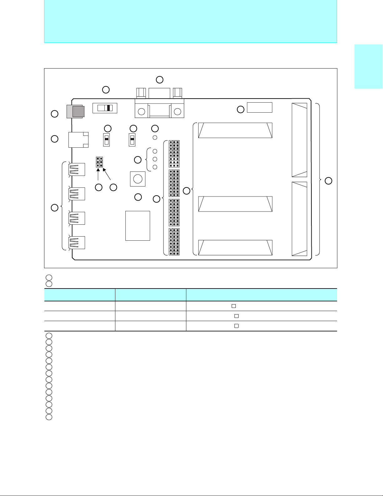
8-bit Proprietary F2MC-8L Family
Evaluation board configuration
8
Support Tools
MC-8LFamily
2
5
Support tools
F
1
DC16 V
IN
USB B
3
USB A1
USB A2
4
1 Power connector
2 Daughter I/F connector
USB A3
USB A4
12 13
10 11
RESET
16
15
9
14
A
2
B1
B2
Part number Target microcontroller Package
7
A
6
B
MB2031-10 MB89P585B/BW
MB2031-11 MB89P589B
MB2031-20 MB89F334
3 USB-B connector
4 USB-A connector
5 RS-232C connector
6 General I/F connector
7 IC socket for clock mounting
8 Power switch
9 Reset switch
10 USB transmission speed setting switch
11 USB transmission speed control switch
12 Short plug for a Power Mode setup (selection of a self-power supply or bus power supply)
13 Short plug for a MCU Power setup (selection of 3.3 V or 5 V)
14 Short plug for a functional setup
15 MCU power LED
16 USB-LED
LQFP-64 (0.5 mm, 10 mm × 10 mm)
LQFP-64 (0.65 mm, 12 mm × 12 mm)
LQFP-120 (0.4 mm, 14 mm × 14 mm)
79
Page 81
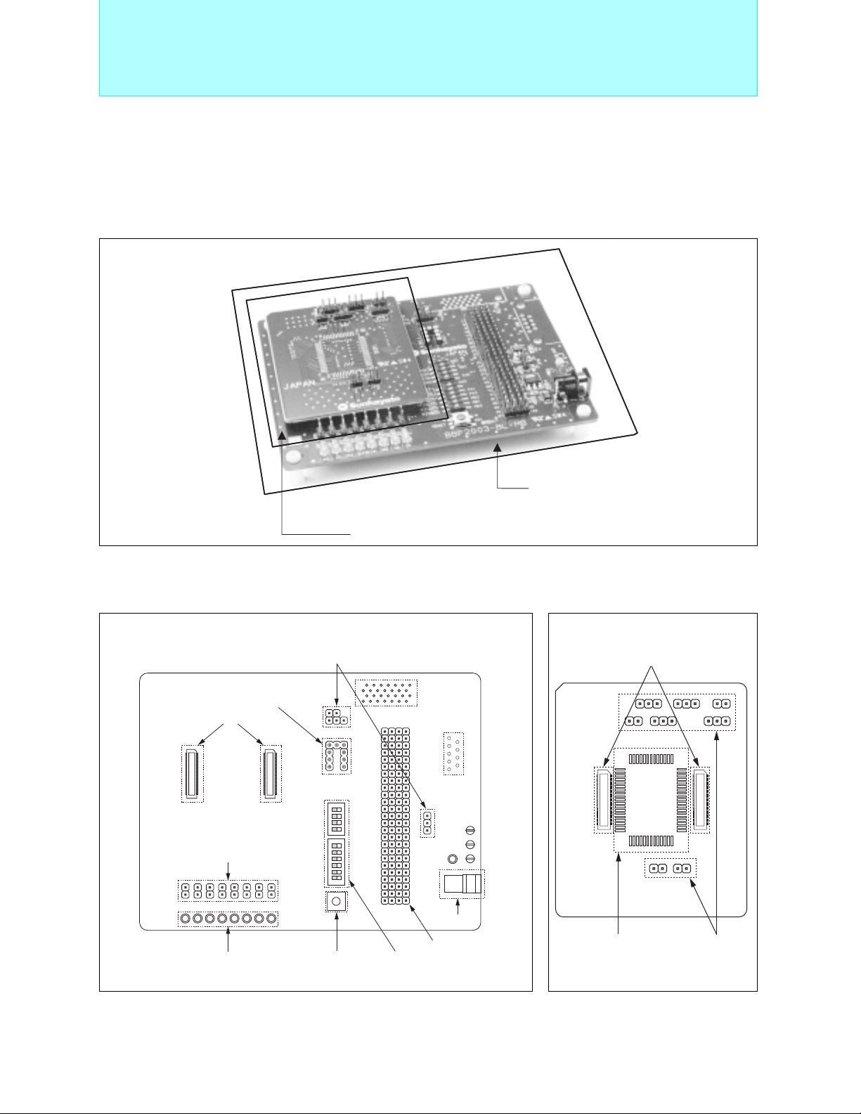
8-bit Proprietary F2MC-8L Family
2
F
MC-8L Family Evaluation board (BBF2003) : Sun Hayato
■
It is an evaluation board corresponding to microcontroller for USB.It contributes to the rise of that the simple evaluation
of operation before including in a visitor’s system is possible, and development efficiency.
It is constituted by evaluation board for USB, and a main board and a daughter board. A main board is common to
each microcontroller products. By changing a daughter board, debugging by ICE combined with the emulator
debugger for microcontroller can be performed.
Support Tools
Evaluation oard configuration
• Main board (BBF2003-8L-MB)
Various setting jumper switches
Socket for main oscillation clocks
Daughter board connection connector
P00 to P07 terminal setting jumper switch
BBF2003-8L-MB (Main board)
BBF2003-8L-64PB (PV carried Daughter board)
PV carried Daughter board
•
MQFP-64 (BBF2003-8L-64PB)
Main board connection connector
*1
*2
Power supply
connector
LED for an output check of
P00 to P07 terminal
*1:Loading of the connector for serial writing (MB89F538/L) .
Contact for detailes : Yokogawa Digital Computer Corporation
*2: Loading of the RS232C(DSUB 9pin) connector (RS232C driver loading).
Reset
button
Various setting DIP switches
Signal check pin
80
Evaluation device
loading part
Various setting
jumper
switches
Page 82

8-bit Proprietary F2MC-8L Family
Product configuration
Support Tools
• Main board
Part number Description
• Locating signal check pin to all terminals
BBF2003-8L-MB
• Function of LED lightning for output port (P00 to P07)
• Evaluate the capability of communication between PC and microcomputer with UART
(mounted DSUB 9pin)
• LIN transceiver (MB89210series)
• Daughter board
Part number Description Target microcontroller Usage
BBF2003-8L-48PB 0.80 mm pitch
BBF2003-8L-64PB 1.00 mm pitch MB89530/A/Hseries MB89PV530CF mounted possible
MB89210series MB89PV210CF mounted possible
MB89470series MB89PV470CF mounted possible
• Main board + daughter board
Part number Description Target microcontroller Usage
BBF2003-8L-48PS 0.80 mm pitch
BBF2003-8L-64PS 1.00 mm pitch MB89530/A/Hseries MB89PV530CF mounted possible
MB89210series MB89PV210CF mounted possible
MB89470series MB89PV470CF mounted possible
MC-8LFamily
2
Support tools
F
• Production configuration
Product name Package
MB89210series MQFP-48(MQP-48C-P01)
MB89470series MQFP-48(MQP-48C-P01)
MB89530/A/Hseries MQFP-64(MQP-64C-P01)
* : The evaluation using the LIN transceiver is possible (MB89210series) .
Contact for detailes : Sun Hayato Co,. td.
81
Page 83
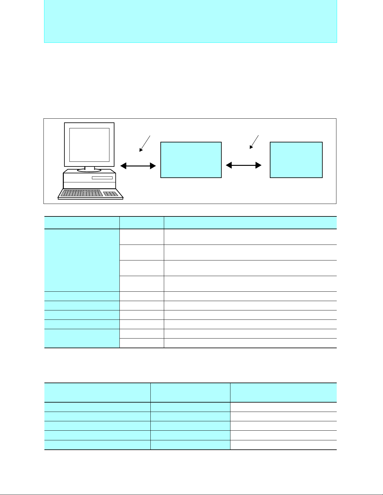
8-bit Proprietary F2MC-8L Family
Serial on board programmer
■
Support Tools
The serial on board programming (Fujitsu standard) in FLASH memory of the F2MC-16LX family or OTPROM of the
2
F
MC-8L family is supported as the following programmer.
1. AF220/AF210/AF120/AF110 (FLASH microcontroller programmer ) : Yokogawa Digital Computer
(1)System configuration
Host interface cable
(AZ221)
RS232C
Flash Microcomputer
Programmer Main Unit
+
Control Module
It is stand-alone and operable.
Standard Target Probe
(AZ210)
CLK synchronous
serial
F2MC-8L/16LX
user’s systemr
(2) Product configuration
Product name Part number Description
AF220/AC4P
Flash Microcontroller Programmer Main Unit
Host Interface Cable AZ221 Writer exclusive use. RS232C cable for PC/AT
Standard Target Probe AZ210 Standard Target Probe (a) : 1 m
Control Modules FF002 or FF004A
Remote Controller AZ290 Remote Controller
Memory card
Contact for detailes : Yokogawa Digital Computer Corporation
Although AF200 (Yokogawa Digital Computer) has ceased, the conventional system configuration is also possible for serial onboard
writing (a standard for FUJITSU) .
AF210/AC4P
AF120/AC4P
AF110/AC4P
/P2 2 MB PC Card
/P4 4 MB PC Card
with Ethernet(10Base-T) Interface
/100V to 220V Power supply adaptor
Basic Model
/100V to 220V Power supply adaptor
Single Operation Model with Ethernet Interface
/100V to 220V Power supply adaptor
Single Operation Model
/100V to 220V Power supply adaptor
Controll modules for F
2
MC-8L OTP microcontroller made by Fujitsu.
(3) OTPROM microcontroller for programming
OTPROM microcontroller
(OTPROM size)
MB89P215 (16 KB) FF004A
MB89F538/L (48 KB) FF201
MB89P558A (48 KB) FF002 Supported
MB89P585B/BW (16 KB) FF004A
MB89P935B (16 KB) FF004A
*1 : In control module FF004A, AF200 (cereal programmer of an old version) is available.
*2 : Needs optional adapter AZ264 (3V conversion adaptet).
Control Module
Status
Supported *
Supported *
Supported *
Supported *
82
1
2
1
1
Page 84

8-bit Proprietary F2MC-8L Family
2. ITF2000 (Serial Gang programmer) : Interface
(1)System configuration
Support Tools
MC-8LFamily
2
Support tools
F
Host interface cable
RS232C
ITF2000
FLASH microcontroller
multiprogrammer
CLK synchronous
serial
F2MC-8L/16LX
user’s system
F2MC-8L/16LX
user’s system
F2MC-8L/16LX
user’s system
It is stand-alone and operable.
(2) Product configuration
Product Function
ITF2000 Main unit of FLASH microcontroller multiprogrammer (with remote software)
ISP2000 Adaptor for on board programming (with main cable)
CF002(for F2MC-8L family)
WF001/F001( for MB89P935B) Microcontroller module
Control software
(3)Programming adaptor
Part number Package Programming adaptor
MB89P935B SSOP-30
TOP2000/SSOP30TP1/P1 (single)
TOP2000/SSOP30TP1/P10 (10 sets)
83
Page 85

16-bit Proprietary F2MC-16L Family
2
MC-16L Family Features
■ F
Features
• Faster version of the F2MC-16 (MB90700 series) with object code compatibility and also allows low
voltage operation.
• Easy programming with plenty of data types, including bit (1-bit), nibble (4-bit), byte (8-bit), word (16-bit), and
long word (32-bit), and 23 types of addressing.
• Bank and linear support of 16Mbytes memory space makes easy migration from external memory sizes to
singlechip systems.
Memory space
FFFFFFH
FF0000H
FE0000H
Bank FF
Bank FE
@RL access
Access possible
to any space PC,
DT, SP or AD
·
·
·
·
·
·
·
·
020000H
010000H
000000H
Bank 01
Bank 00
•Registers
Dedicated registers
General-purpose registers: 10 × 16-bit per bank, 32 banks Max.
Dedicated registers
AH
32 bits
AL
USP
SSP
PS
PC
16 bits
Accumulator
User stack pointer
System stack pointer
Processor status
Program counter
Direct page register
DPR
System stack upper limit register
Program bank register
PCB
Data bank register
DTB
User stack bank register
USB
System stack bank register
SSB
ADB
Additional data bank register
8 bits
000180H+(RP×10H) →
16MB
FFFFH
0380H
General-purpose
0180H
0100H
0000H
General-purpose registers
R7 R6 (RW7)
R5 R4 (RW6)
R3 R2 (RW5)
R1 R0 (RW4)
RW3
RW2
RW1
RW0
16 bits
register area
I/O area
Upper address
(RL3)
(RL2)
(RL1)
(RL0)
Lower address
• Pipeline processing using 4 bytes cue (minimum instruction execution time: 62.5 ns/16 MHz)
• Powerful real time processing using 8-level hardware support priority interrupts and extended intelligent I/O ser-
vice functions.
• Extended C language and real time operating system instructions (SP indirect addressing, etc.)
• Can utilize external 4 MHz oscillator to run at 16 MHz internally by using a built-in clock multiplier circuitry.
2
• Number of basic instructions: 340 (fully compatible with the F
MC-16/16H)
84
Page 86
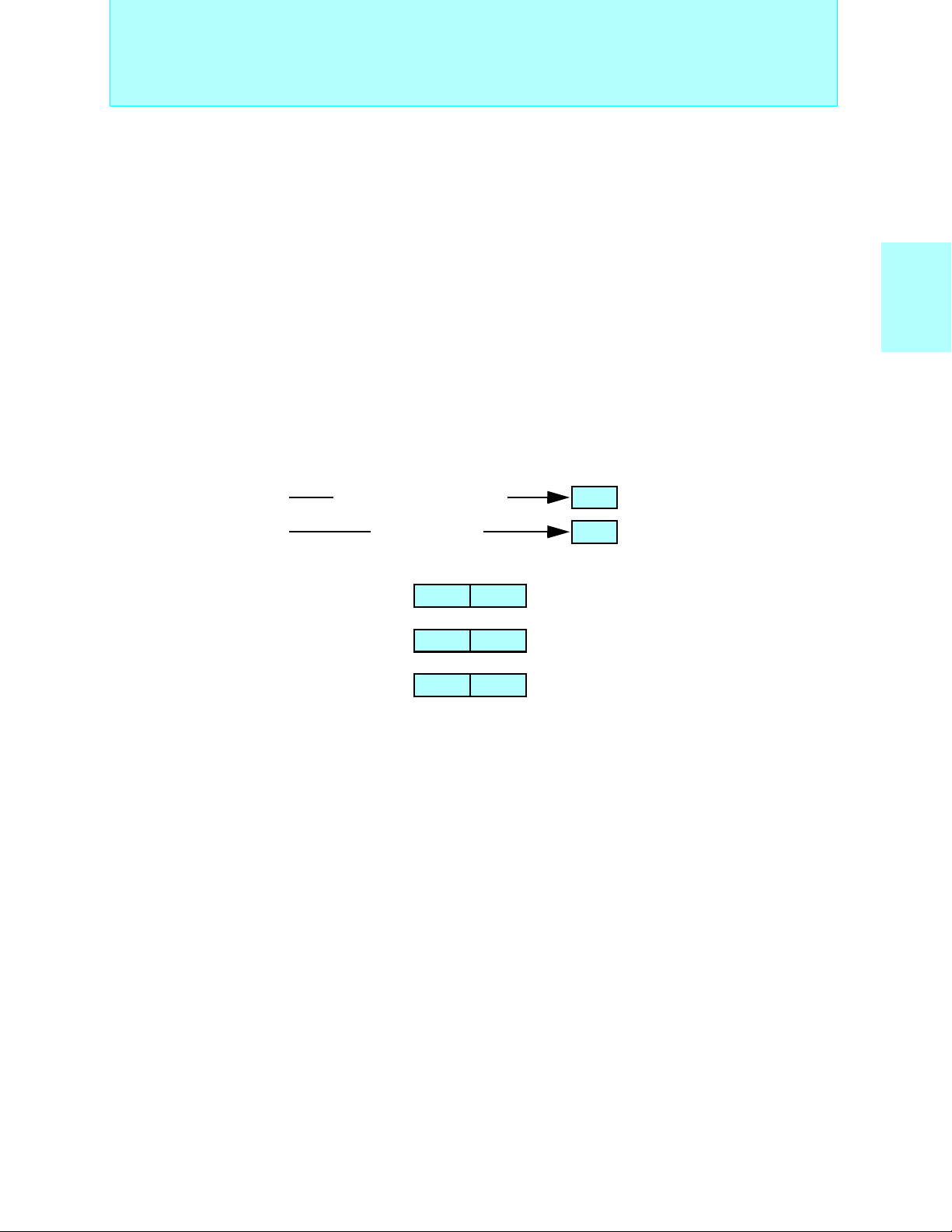
16-bit Proprietary F2MC-16L Family
Addressing and Super-accumulator
■ Main Addressing Modes
(can be used by transfer and arithmetic instructions)
• Bit addressing
Direct bit: I/O area (2 Kbits) + area inside DPR page (2 Kbits)
Any bit within 64 Kbytes may be specified.
• Indirect addressing
@RWi, @RWi+, @RWi+disp16, @RLi+disp8, @RWj+disp8 (i = 0 to 3), (j = 0 to 7)
@RW0+RW7
@RW1+RW7
@PC+disp16
@A
• Direct addressing
R0 to R7, RW0 to RW7, RL0 to RL3
dir, addr16, io, addr24
■ Super Accumulator
• 32-bit accumulator using AH:AL (16 bits:16 bits) as a pair.
• Data precision verification function
F8
F8
• Data keep function (available for data types of 16-bit word length and less)
For example, MOV instruction
MOVX instruction
AH AL
Xa
↓
ab
↓
aa+b
MOV A,#b
ADDW A
00F8
FFF8
Zero extension
Sign extension
MC-16L Family
2
F
85
Page 87

16-bit Proprietary F2MC-16L Family
2
■ Extended Intelligent I/O Service (EI
OS)
Extended Intelligent I/O Service
• In addition to programing being made easier because htere is no need to execute unnecessary program trans-
fers, higher speeds for transfer, service response and overall system controls are realized.
• Since CPU micro-instructions executs transfer functions, multi-channel systems can be realized at no extra cost.
• Since I/O transfers can be stopped when a condition is generated such as when invalid data is received,
performance loss due to transferring unnecessary data can be avoided because there is no programming load.
• It is possible to specify incrementing or decrementing of buffer address and I/O register address.
• It is possible to specify the entire 00 banks I/O register addresses, the data counter can be set up to 64000.
Memory space
I/O
I/O registers
register
Peripheral
3
IOA
(I/O address)
4
3
ISD
BAP
(memory address)
Memory
2 interrupt requests
Interrupt controller
Interrupt control register
Operation mechanism
1. An I/O transfer request is generated.
2. The interrupt controller selects the descriptor.
3. Transfer source and destination addresses are read out of the
descriptor.
4. Data is transferred between I/O register and memory space.
1
ICS
I/O
(000000
H to 0000FFH) (000000H to FFFFFFH)
• Execution speed
From request, to completion of transfer: 32 cycles = 2.00 µs (@16 MHz)
Memory
86
Page 88

16-bit Proprietary F2MC-16L Family
Real time control
F2MC-16L Family Product Range
MB90650A
ROM64-128KB
Cellular phone,
battery backuped
products
MB90630A
ROM32-64KB
Cameras, copiers,
office automation
equipment
Product Range
Page
90
Page
90
MC-16L Family
2
F
AC motor
control macro
LCD controller
driver
Standard
MB90660A
ROM 32-48KB
Air conditioning,
general-purpose
inverters
Page
88
MB90670
ROM 16-48KB
Consumer and
industrial
equipment
MB90675
ROM 32-64KB
Consumer and
industrial
equipment
Page
84
MB90620A
ROM 32-48KB
Cameras,
consumer products
MB90610A
No ROM
Consumer,
industrial
(host type)
Page
84
Page
88
Page
86
MB90640A
ROM 64KB
Consumer,
industrial
Page
86
64-pin 80-pin 100-p in 120-pin
87
Page 89
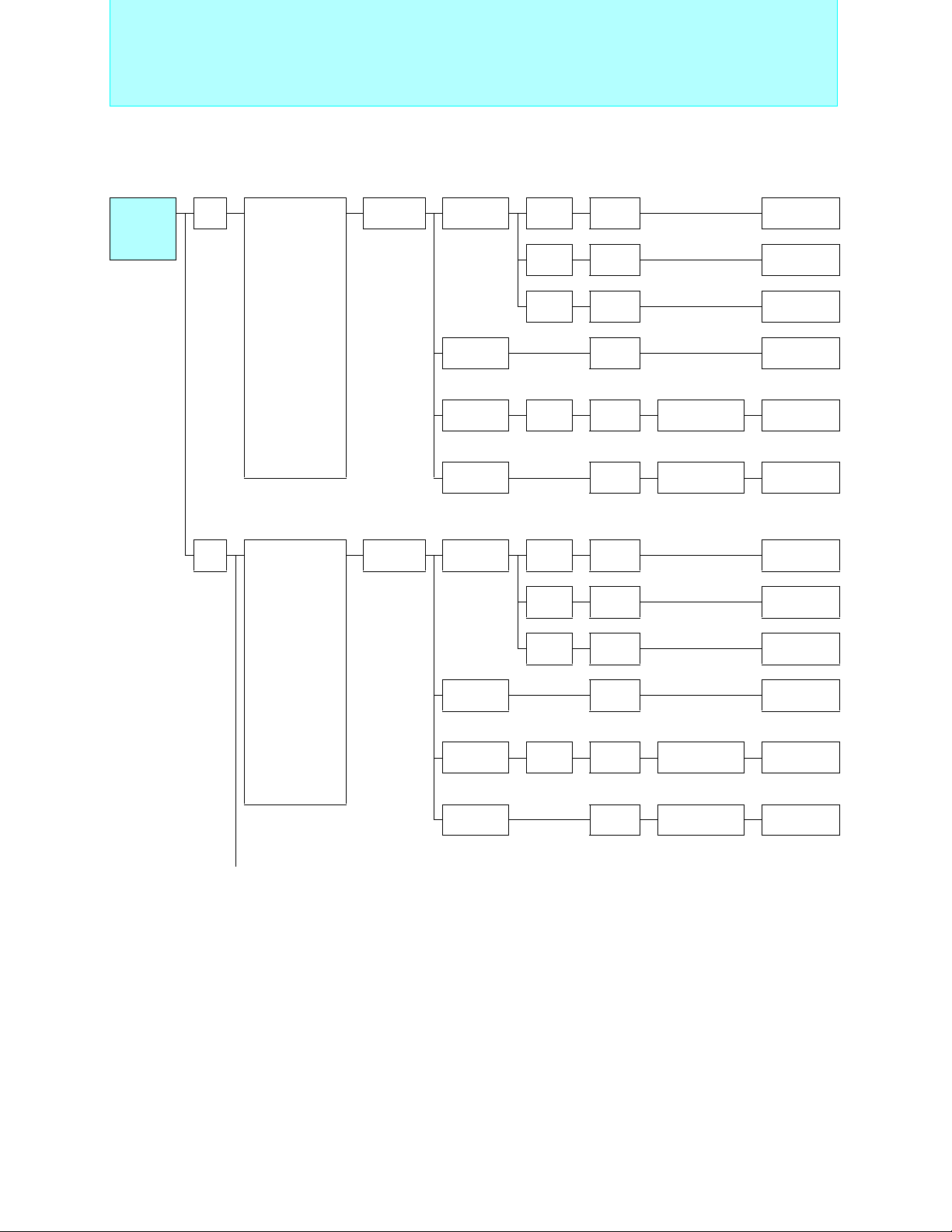
16-bit Proprietary F2MC-16L Family
Standard Products
F2MC-16L
Family
Standard
Products
Pin
count
80
100
Main functions
UART (2ch.),
reload timer
(16-bit × 2ch.),
free-run timer
(24-bit × 1ch.),
PPG timer
(8-bit × 2ch.),
A/D converter
(10/8-bit × 8ch.),
input capture
(4ch.),
output compare
(8ch.),
clock duty control,
external interrupts (4ch.),
gear function
UART (2ch.),
reload timer
(16-bit × 2ch.),
free-run timer
(24-bit × 1ch.),
PPG timer
(8-bit × 2ch.),
A/D converter
(10/8-bit × 8ch.),
input capture
(4ch.),
output compare
(8ch.),
clock duty control,
external interrupts (4ch.),
gear function
Series
name
MB90670
series
MB90675
series
Type ROM RAM
Mass
production
ROM 2 KB MB90T673
OTPROM 48 KB 2 KB
Evaluation
device
Mass
production
ROM 3 KB MB90T678
OTPROM 64 KB 3 KB
Evaluation
device
16 KB 640 B MB90671
32 KB 1.64 KB MB90672
48 KB 2 KB MB90673
Equivalent device
MB90670
series
Evaluation target device
4 KB
32 KB 1.64 KB MB90676
48 KB 2 KB MB90677
64 KB 3 KB MB90678
4 KB
MB90670/675
series
Equivalent device
MB90675
series
Evaluation target device
MB90670/675
series
Part
number
MB90P673
MB90V670
MB90P678
MB90V670
88
(Continued)
Page 90
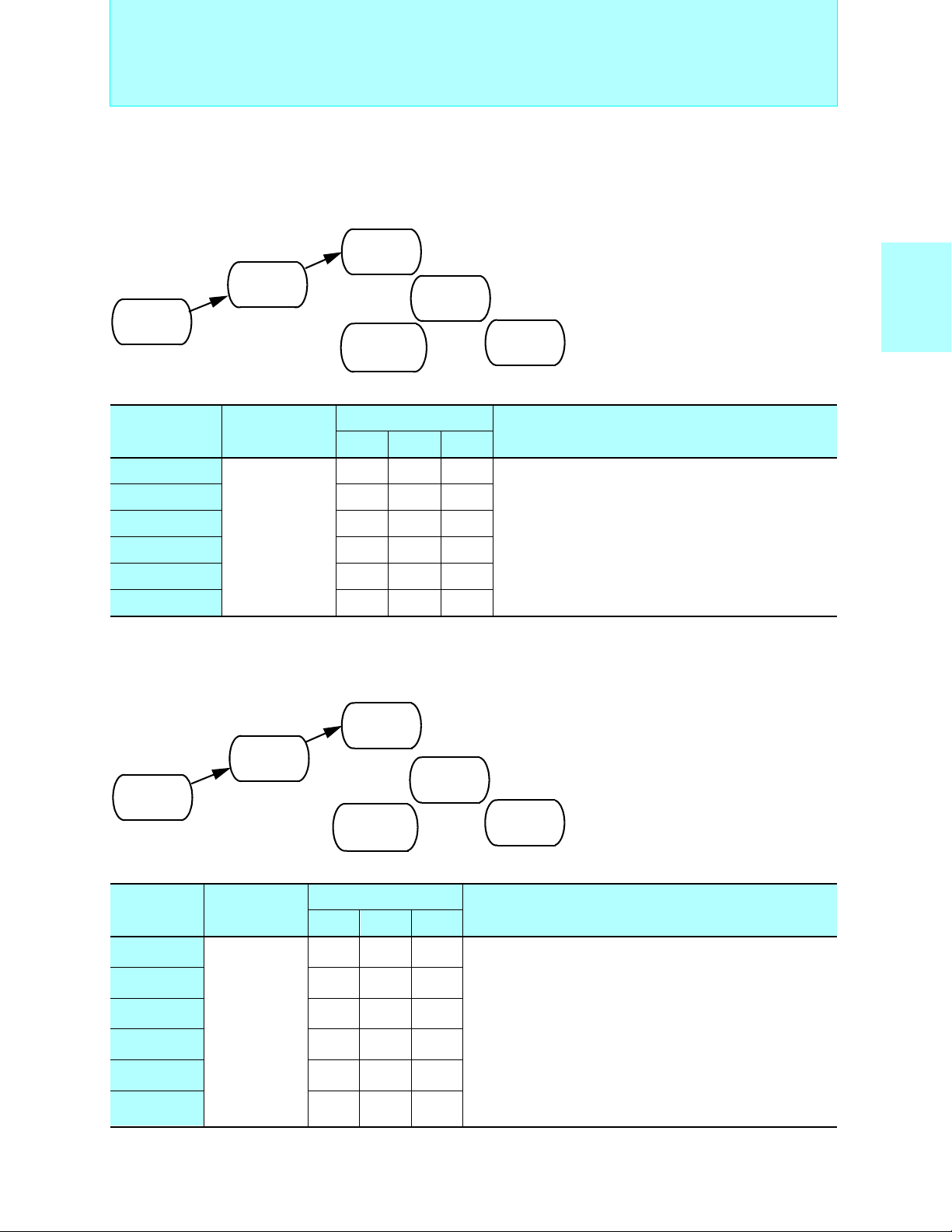
16-bit Proprietary F2MC-16L Family
2
MC-16L Family Standard Products
■ F
Standard Products
MB90670 Series
For mechanical electronics control, automobile ABS control, AV equipment, high level home appliances etc.
• Maximum internal clock frequency:16 MHz
• Minimum execution time:62.5 ns
• Operating temperature range:-40°C to +85°C
MB90671
ROM16KB
RAM640B
MB90672
ROM32KB
RAM1.64KB
MB90673
ROM48KB
RAM2KB
MB90T673
ROM External
RAM2KB
MB90P673
OTPROM48KB
RAM2KB
MB90V670
RAM4KB
<Evaluation device>
MC-16L Family
2
F
Operating
Part number
power supply
voltage (V)
MB90671
MB90672 80P 80P −
MB90673 80P 80P −
MB90T673 80P 80P −
MB90P673 80P 80P −
MB90V670 −−256C
Packages: P - plastic, C - ceramic
+2.7 to +5.5
Package
QFP LQFP PGA
80P 80P −
Functions
I/O ports: 65 Max.
Timer/counter: 16-bit × 2ch.
Timebase timer (WDT): 18-bit × 1ch.
PPG timer: 8-bit × 2ch. (16-bit × 1ch.)
UART: 2ch.
Real time I/O: 24-bit input capture unit (ICU) × 4ch.
24-bit output compare unit (OCU) × 8ch.
Analog section:10/8-bit A/D converter × 8ch.
External interrupts: 4
Low-power consumption modes:Sleep, stop, time base timer,
CPU intermittent operation mode
MB90675 Series
For mechanical electronics control, automobile ABS control, AV equipment, high level home appliances etc.
MB90676
ROM32KB
RAM1.64K
MB90677
ROM48KB
RAM2KB
MB90678
ROM64KB
RAM3KB
MB90T678
ROM External
RAM 3KB
MB90P678
OTPROM64KB
RAM3KB
<Evaluation device>
MB90V670
RAM4KB
• Maximum internal clock frequency:16 MHz
• Minimum execution time:62.5 ns
• Operating temperature range:-40°C to +85°C
Operating
Part number
power supply
voltage (V)
MB90676
MB90677 100P 100P −
MB90678 100P 100P −
MB90T678 100P 100P −
MB90P678 100P 100P −
MB90V670 −−256C
Packages: P - plastic, C - ceramic
+2.7 to +5.5
Package
QFP LQFP PGA
100P 100P −
Functions
I/O ports: 84 Max.
Timer/counter: 16-bit × 2ch.
Timebase timer (WDT):18-bit × 1ch.
PPG timer: 8-bit × 2ch. (16-bit × 1ch.)
UART: 2ch.
2
I
C bus interface: 1ch.
Real time I/O: 24-bit input capture unit (ICU) × 4ch.
Analog section: 10/8-bit A/D converter × 8ch.
External interrupts: 4
Low-power consumption modes:Sleep, stop,time base timer,
24-bit output compare unit (OCU) × 8ch.
CPU intermittent operation mode
89
Page 91
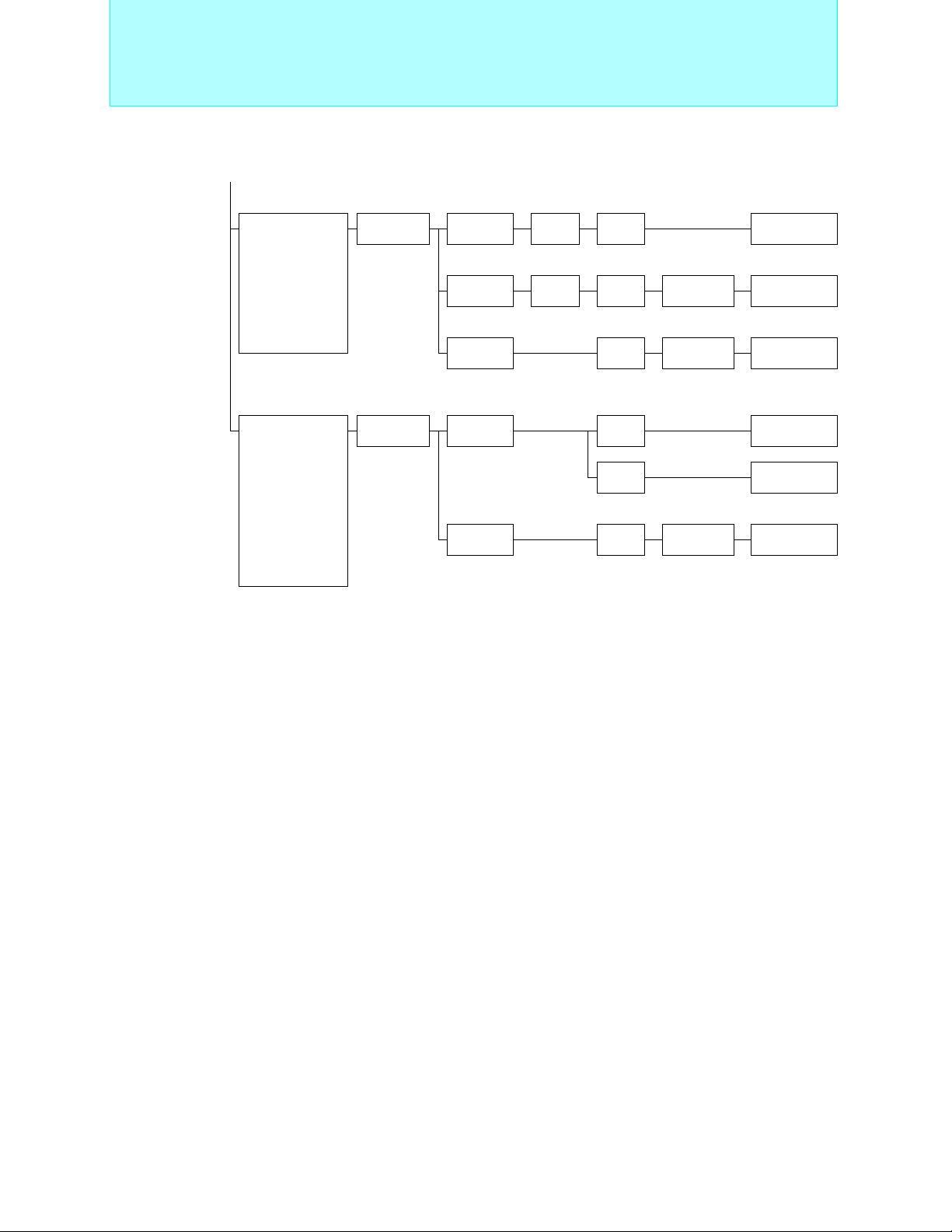
16-bit Proprietary F2MC-16L Family
Standard Products
(Continued)
Main functions
UART (2ch.),
external interrupts
(8ch.),
chip select outputs
(8ch.),
reload timer
(16-bit × 5ch.)
PPG timer
(8-bit × 2ch.)
UART (3ch.),
A/D converter
(10-bit × 8ch.),
PPG timer
(8-bit × 2ch.),
reload timer
(16-bit × 4ch.),
chip select output
(8ch.),
external interrupts
(8ch.)
Series
name
MB90640A
series
MB90610A
series
Type ROM RAM Part number
Mass
production
OTPROM 64 KB 2 KB MB90641A MB90P641A
Evaluation
device
Mass
production
Evaluation
device
64 KB 2 KB MB90641A
Equivalent device
Evaluation target device
4 KB
1 K B MB90611A
3 KB MB90613A
4 KB
MB90640A
series
Evaluation target device
MB90610A
series
MB90V640A
MB90V610A
90
Page 92

16-bit Proprietary F2MC-16L Family
MB90640A Series
For industrial applications, OA equipment etc.
MB90P641A
MB90641A
ROM64KB
RAM2KB
Operating
Part number
power supply
voltage (V)
MB90641A
MB90P641A 100P 100P −
MB90V640A −−256C
+4.5 to +5.5
OTPROM64KB
RAM2KB
Package
QFP LQFP PGA
100P 100P −
MB90V640A
RAM4KB
<Evaluation device>
I/O ports: 83 Max.
Timebase timer (WDT): 18bit × 1ch.
PPG timer: 8-bit × 2ch. (16-bit × 1ch.)
UART: 2ch.
Reload timer: 16-bit × 5ch.
External interrupts: 8ch.
Chip select output pin: 8
External bus interface: selective between non-multiplex and
multiplex
Low-power consumption modes: Sleep, stop, time base timer,
Standard Products
• Maximum internal clock frequency: 16 MHz
• Minimum execution time: 62.5 ns
• Operating temperature range: -40°C to +85°C
Functions
CPU intermittent operation mode
MC-16L Family
2
F
Packages: P - plastic, C - ceramic
MB90610A Series
For industrial applications, OA equipment control, process control, etc.
MB90613A
RAM3KB
MB90V610A
MB90611A
RAM1KB
Operating
Part number
power supply
voltage (V)
MB90611A
MB90613A 100P 100P −
MB90V610A −−256C
Packages: P - plastic, C - ceramic
+2.7 to +5.5
Package
QFP LQFP PGA
100P 100P −
RAM4KB
<Evaluation device>
I/O ports: 57 max. (8, 16-bit multiplexed mode)
Timer/counter: 16-bit × 2ch.
Timebase timer (WDT): 18-bit × 1ch.
PPG timer: 8-bit × 2ch. (16-bit × 1ch.)
UART: 3ch.
Analog section: 10-bit A/D converter × 8ch.
External interrupts: 8ch.
Chip select output pin: 8
External bus interface: selective between non-multiplex and
multiplex
Low-power consumption modes:Sleep, stop, time base timer,
• Maximum internal clock frequency: 16 MHz
• Minimum execution time: 62.5 ns
• Operating temperature range: -40°C to +85°C
Functions
41 max. (16-bit non-multiplexed mode)
49 max. (8-bit non-multiplexed mode)
CPU intermittent operation mode
91
Page 93

16-bit Proprietary F2MC-16L Family
Internal LCD Controller/Driver Products
Internal AC Motor Control Macro Products
F2MC-16L
Family
Internal
LCD
Controller
/Driver
Products
F2MC-16L
Family
Internal
AC Motor
Control
Macro
Products
Pin
count
100
Pin
count
64
Main functions
UART (1ch.),
reload timer
(16-bit × 3ch.),
free-run timer
(16-bit × 2ch.),
PPG timer
(16-bit × 2ch.),
A/D converter
(10/8-bit × 4ch.),
LCD controller
driver (32 seg. × 4
com.),
clock duty control,
external interrupts
(8ch.),
gear function
Main functions
Timer unit for
inverter control,
reload timer
(16-bit × 4ch.),
PWM timer
(8-bit × 1ch.),
UART (1ch.),
A/D converter
(10-bit × 8ch.),
external interrupts
(8ch.)
Series
name
MB90620A
series
Series
name
MB90660A
series
Type ROM RAM Part number
Mass
production
OTPROM 48 KB 2 KB MB90623A MB90P623A
Evaluation
device
Type ROM RAM Part number
Mass
production
OTPROM 48 KB 2 KB MB90663A MB90P663A
Evaluation
device
32 KB 1.64 KB MB90622A
48 KB 2 KB MB90623A
Equivalent device
Evaluation target device
3 KB
32 KB 1 KB MB90662A
48 KB 2 KB MB90663A
4 KB
MB90620A
series
Equivalent device
Evaluation target device
MB90660A
series
MB90V620A
MB90V660A
92
Page 94
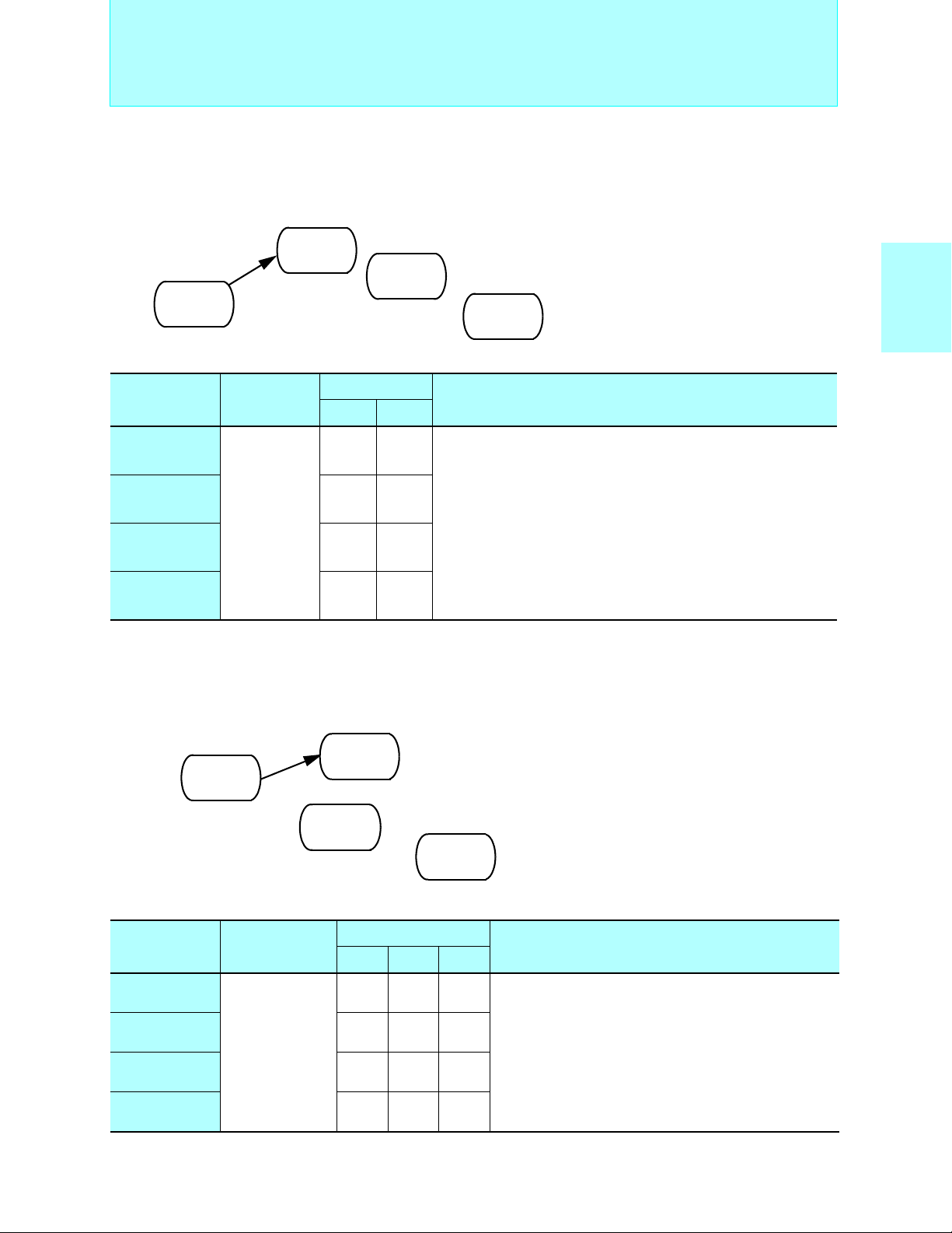
C
16-bit Proprietary F2MC-16L Family
2
MC-16L Family Internal LCD Controller/Driver Products
■ F
Internal LCD Controller/Driver Products
Internal AC Motor Control Macro Products
MB90620A Series
Internal LCD controller/driver, for AV equipment, high level home appliances, etc.
• Maximum internal clock frequency: 12 MHz (32.768 kHz)
• Minimum execution time: 83.3 ns (122.1 µs)
• Operating temperature range: -40°C to +85°C
MB90V620A
RAM3KB
MB90622A
ROM32KB
RAM1.64KB
MB90623A
ROM48KB
RAM2KB
MB90P623A
OTPROM48KB
RAM2KB
<Evaluation device>
MC-16L Family
2
F
Operating
Part number
power supply
voltage (V)
MB90622A
MB90623A 100P −
+4.0 to +5.5
MB90P623A 100P −
MB90V620A − 256C
Packages: P - plastic, C - ceramic
Package
LQFP PGA
100P −
Functions
I/O ports: 59 Max.
Timer/counter: 16-bit × 3ch. (reload), 16-bit × 2ch. (free-run)
Timebase timer (WDT): 18-bit × 1ch.
PPG timer: 16-bit × 2ch.
UART: 1ch.
SIO: 1ch.
Analog section: 8/10-bit A/D converter × 4ch.
LCD controller/driver: 128 elements, 2 to 4common,
16 to 32 segments, 16 × 8-bit LCD display RAM
External interrupts: 8
Low-power consumption modes:Sleep, stop, CPU intermittent
operation, watch, time base timer mode
■ F2MC-16L Family Internal AC Motor Control Macro Products
MB90660A Series
For industrial applications, OA equipment control, process control, etc.
MB90662A
ROM32KB
RAM1KB
MB90663A
ROM48KB
RAM2KB
MB90P663A
OTPROM48KB
RAM2KB
MB90V660A
RAM4KB
<Evaluation device>
• Maximum internal clock frequency: 16 MHz
• Minimum execution time: 62.5 ns
• Operating temperature range: -40°C to +85°
Operating
Part number
power supply
voltage (V)
MB90662A
MB90663A 64P 64P −
+2.7 to +5.5
MB90P663A 64P 64P −
MB90V660A −−256C
Packages: P - plastic, C - ceramic
Package
QFP SDIP PGA
64P 64P −
Functions
I/O ports: 51 Max.
Timer/counter: 16-bit × 4ch.
Timebase timer (WDT):18-bit × 8ch.
PWM timer: 8-bit × 1ch.
UART: 1ch.
Analog section: 8/10-bit A/D converter × 8ch.
External interrupts: 8
Low-power consumption modes:Sleep, stop, CPU
intermittent operation, time base timer mode
93
Page 95
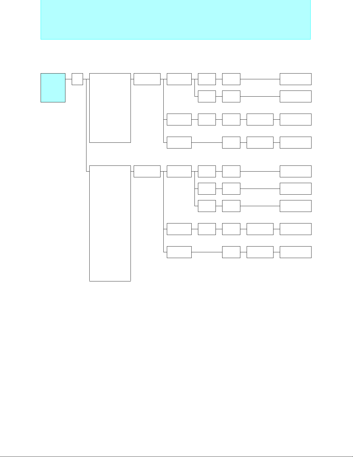
16-bit Proprietary F2MC-16L F amily
Real Time Control Products
F2MC-16L
Family
Real Time
Control
Products
Pin
count
100
Main functions
A/D converter
(10-bit × 8ch.),
D/A converter
(8-bit × 2ch.),
UART (1ch.),
SIO(2ch.),
PPG timer
(8-bit ×2ch.),
up/down counter
(8-bit × 2ch.),
external interrupts
(8ch.)
Dual clock
A/D converter
(10-bit × 8ch.),
D/A converter
(8-bit × 2ch.),
UART (1ch.),
SIO (2ch.),
PPG timer
(8-bit ×2ch.),
external interrupts
(8ch.),
up/down counter
(8bit × 2ch.),
2
I
C interface
(1ch.),
input capture
(2ch.),
output compare
(4ch.),
DTMF (1ch.)
Series
name
MB90630A
series
MB90650A
series
Type ROM RAM Part number
Mass
production
OTPROM 64 KB 3 KB MB90634A MB90P634A
Evaluation
device
Mass
production
FLASH 256 KB 8 KB MB90654A MB90F654A
Evaluation
device
32 KB 1 KB MB90632A
64 KB 2 KB MB90634A
Equivalent device
Evaluation target device
4 KB
64 KB 3 KB MB90652A
128 KB 5 KB MB90653A
256 KB 8 KB MB90654A
FRASH ROM Equivalent device
6 KB
MB90630A
series
Evaluation target device
MB90650A
series
MB90V630A
MB90V650A
94
Page 96
2
MC-16L Real Time Control Products
■ F
MB90630A Series
For consumer products, etc.
MB90634A
ROM 64 KB
MB90632A
ROM 32 KB
RAM 1 KB
RAM 2 KB
MB90P634A
OTPROM 64 KB
RAM 3 KB
• Maximum internal clock frequency: 16 MHz
• Minimum execution time: 62.5 ns
• Operating temperature range: -40°C to +85°C
MB90V630A
RAM 4 KB
<Evaluation device>
Operating
Part number
power supply
voltage (V)
MB90632A
MB90634A 100P 100P −
+2.7 to +5.5
MB90P634A 100P 100P −
MB90V630A −−256C
Packages: P - plastic, C - ceramic
Package
LQFP QFP PGA
100P 100P −
MB90650A Series
For cellular phones, battery backuped products, etc.
Functions
I/O ports: 82 Max.
Timebase timer (WDT): 18-bit × 1 ch.
PPG timer: 8-bit × 2ch. (16-bit × 1 ch.)
UART: 2 ch.
SIO: 2 ch.
Real time I/O:16-bit input capture unit (ICU) × 2 ch.
Analog section: 10-bit A/D converter × 8 ch.
Encoder macro: 8-bit up/down counter × 2 ch. (16-bit × 1 ch.)
External interrupts: 8
Low-power consumption modes:Sleep, stop, time base timer mode
16-bit output compare unit (OCU) × 4 ch.
16-bit free running timer × 1 ch.
8-bit D/A converter × 2 ch.
Operating
Part number
power supply
voltage (V)
MB90652A
MB90653A 100P 100P −
MB90654A 100P 100P −
MB90F654A +2.4 to +3.6 100P 100P −
MB90V650A +2.7 to +3.6 −−256C
Packages: P - plastic, C - ceramic
+2.2 to +3.6
Package
QFP LQFP PGA
100P 100P −
Functions
I/O ports: 79 Max.
Dual clock
Timebase timer (WDT): 18-bit × 1 ch.
PPG timer: 8-bit × 2 ch. (16-bit × 1 ch.)
UART: 1 ch.
2
C interface: 1 ch.
I
SIO: 2 ch.
Real time I/O: 16-bit input capture unit (ICU) × 2 ch.
Analog section:10-bit A/D converter × 8 ch.
Encoder macro: 8-bit up/down counter × 2 ch. (16-bit × 1 ch.)
DTMF: 1 ch.
External interrupts: 8
When a dual power supply is used, a part of I/O is 5V pin.
Low-power consumption modes:Sleep, stop, watch,
16-bit output compare unit (OCU).× 4 ch.
8-bit D/A converter× 2 ch.
CPU intermittent operation, time base timer mode
95
Page 97

16-bit Proprietary F2MC-16LX Family
Features
■ F2MC-16LX Family Features
•F2MC-16LX family is a high-performance 16-bit microcomputer having the upward compatibility with the
F2MC-16L family.
• Supporting 16-Mbyte memory space.
Memory space
Access possible
to any space PC,
DT, SP or AD
FFFFFFH
FF0000H
FE0000H
Bank FF
Bank FE
·
·
·
·
·
·
·
·
020000H
010000H
000000H
Bank 01
Bank 00
•Registers
Dedicated registers
General-purpose registers: 10 × 16-bit per bank, 32 banks Max.
Dedicated registers
@RL access
16MB
FFFFH
0380H
General-purpose
register area
0180H
0100H
I/O area
0000H
General-purpose registers
AH
32 bits
AL
USP
SSP
PS
PC
16 bits
Accumulator
User stack pointer
System stack pointer
Processor status
Program counter
Direct page register
DPR
Program bank register
PCB
Data bank register
DTB
User stack bank register
USB
System stack bank register
SSB
ADB
Additional data bank register
8 bits
32 Max.
000180H+(RP×10H) →
R7 R6
R5 R4
R3 R2
R1 R0
RW3
RW2
RW1
RW0
16 bits
(RW7)
(RW6)
(RW5)
(RW4)
Upper address
(RL3)
(RL2)
(RL1)
(RL0)
Lower address
• Clock multiplier circuit (×1/2, ×2, ×3, and ×4) to protect your surrounding environment
Reducing the radiation interference
High-speed operation using the inexpensive low-speed oscillator (external 4 MHz; internal 16 MHz max.)
• Power management capabilities to contribute to the conservation of energy:
STOP, SLEEP, subclock, hardware standby
• AL 2 layers 0.5 µm (reducing the chip footprint)
• Low-voltage, low-power voltage dissipation
Supporting large memory (up to 256 Kbytes for ROM; up to 10 Kbytes for RAM)
• Power dissipation reduced by 60 % as compared to the earlier product (5 V compatible product)
96
Page 98
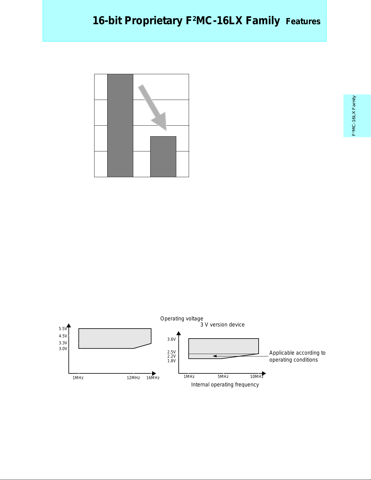
16-bit Proprietary F2MC-16LX Family
• Reduced power dissipation (5 V compatible products)
100%
75
Features
50
25
0
FMC-16L FMC-16LX
• Noise protection
Adoptation of multiplier circuit
Circuit optimization
Built-in noise filters for all pins
• Bus control
Bus sizing function: 8-bit or 16-bit bus width selectable
Software switching between non-multibus and multibus (device)
Supporting 8 ch. chip select (device)
• Built-in extended intelligent I/O service function (simple DMA function)
• Program patch processing function
Avoiding bugs by applying patches on a masked ROM
• Addition of signed multiplication and division instruction
• High-speed interrupt transition
High-speed transition achieved at the time of multiple interrupts
Expansion achieved to low-voltage and high-speed operation
5.0 V: Minimum machine clock of 62.5 ns/16 MHz
2.2 V: Minimum machine clock of 100 ns/10 MHz
MC-16LX Family
2
F
Operating voltage
5.5V
4.5V
3.3V
3.0V
1MHz 12MHz 16MHz
5 V version device
Internal operating frequency
Operating voltage
3.6V
2.5V
2.2V
1.8V
1MHz 5MHz 10MHz
Internal operating frequency
3 V version device
Applicable according to
operating conditions
97
Page 99
16-bit Proprietary F2MC-16LX Family
Addressing, Super-accumulator, and
Fields for Product Expanision
■ Main Addressing Modes
• Bit addressing
Direct bit: I/O area (2Kbits) + area inside DPR page (2Kbits)
Any bit within 64 Kbytes may be specified.
• Indirect addressing
@RWi, @RWi+, @RWi+disp16, @RLi+disp8, @RWj+disp8 (i = 0 to 3), (j = 0 to 7)
@RW0+RW7
@RW1+RW7
@PC+disp16
@A
• Direct addressing
R0 to R7, RW0 to RW7, RL0 to RL3
dir, addr16, io
(Can be used by transfer and arithmetic instructions)
■ Super Accumulator
• 32-bit accumulator using AH:AL (16 bits:16 bits) as a pair.
• Data precision verification function
Zero extension
MOV A,#b
ADDW A
00F8
FFF8
Sign extension
F8
F8
• Data keep function (available for data types of 16-bit word length and less)
For example, a MOV instruction
MOVX instruction
AH AL
X a
↓
a b
↓
a a+b
■ Fields for Product Expansion
Applicable to the following fields:
• Digital AV system→ (Serial communication enhancement, large size)
• Mobile equipment system→ (Low-power dissipation)
• File-related system→ (Signal processing enhancement)
• Network system→ (Telecommunication macro enhancement)
98
Page 100

99
 Loading...