

Page 1

English
FUJITSU Server BS2000
SE700 / SE500 / SE300
Administration and Operation
User Guide
Valid for:
M2000 V6.2A SP1 (V6.2A05 and higher)
X2000 V6.0A SP1 (V6.2A05 and higher)
HNC V6.2A SP1 (V6.2A05 and higher)
Edition March 2018
Page 2

Comments… Suggestions… Corrections…
The User Documentation Department would like to know your
opinion on this manual. Your feedback helps us to optimize our
documentation to suit your individual needs.
Feel free to send us your comments by e-mail to:
manuals@ts.fujitsu.com
Certified documentation
according to DIN EN ISO 9001:2008
To ensure a consistently high quality standard and
user-friendliness, this documentation was created to
meet the regulations of a quality management system which
complies with the requirements of the standard
DIN EN ISO 9001:2008.
cognitas. Gesellschaft für Technik-Dokumentation mbH
www.cognitas.de
Copyright and Trademarks
Copyright © 2018 Fujitsu Technology Solutions GmbH.
All rights reserved. Delivery subject to availability; right of technical modifications reserved.
All hardware and software names used are trademarks of their respective manufacturers.
The Xen® mark is a trademark of Citrix Systems, Inc., which manages the mark on behalf of the Xen open source
community. The Xen® mark is registered with the U.S. Patent and Trademark Office, and may also be registered in
other countries.
Novell and SUSE are registered trademarks of Novell, Inc. in the USA and other countries.
Linux is a registered trademark of Linus Torvalds.
Windows® is a registered trademark of Microsoft Corporation.
The Linux-based basic software M2000, X2000, and HNC which is installed on the Management Unit, Server Unit
x86, and HNC contains Open Source Software. The licenses for this can be found in the LICENSES directory on the
relevant installation DVD.
This manual is printed
on paper treated with
chlorine-free bleach.
Page 3

Content
1 Introduction . . . . . . . . . . . . . . . . . . . . . . . . . . . . . . . . . . . . . . 11
1.1 Documentation for the SE servers . . . . . . . . . . . . . . . . . . . . . . . . . . 13
1.2 Objective and target groups of this manual . . . . . . . . . . . . . . . . . . . . . 14
1.3 Summary of contents . . . . . . . . . . . . . . . . . . . . . . . . . . . . . . . . . 15
1.4 Changes since the last edition of the manual . . . . . . . . . . . . . . . . . . . . 16
1.5 Notational conventions . . . . . . . . . . . . . . . . . . . . . . . . . . . . . . . . 18
1.6 Names and abbreviations . . . . . . . . . . . . . . . . . . . . . . . . . . . . . . 19
1.7 Open Source Software . . . . . . . . . . . . . . . . . . . . . . . . . . . . . . . . 20
2 Architecture and strategies . . . . . . . . . . . . . . . . . . . . . . . . . . . . . 21
2.1 Architecture . . . . . . . . . . . . . . . . . . . . . . . . . . . . . . . . . . . . . . 21
2.2 Software of the SE server . . . . . . . . . . . . . . . . . . . . . . . . . . . . . . 24
2.2.1 Structure of the software . . . . . . . . . . . . . . . . . . . . . . . . . . . . . . . . 24
2.2.2 Software status, system version and update status . . . . . . . . . . . . . . . . . . 25
2.2.3 Updates to the basic software and add-on packs . . . . . . . . . . . . . . . . . . . 26
2.2.3.1 Naming conventions . . . . . . . . . . . . . . . . . . . . . . . . . . . . . . . . 26
2.2.3.2 Security fix . . . . . . . . . . . . . . . . . . . . . . . . . . . . . . . . . . . . . 27
2.2.3.3 Hot fix . . . . . . . . . . . . . . . . . . . . . . . . . . . . . . . . . . . . . . . 27
2.2.3.4 Add-on pack . . . . . . . . . . . . . . . . . . . . . . . . . . . . . . . . . . . . 27
2.2.4 Management applications . . . . . . . . . . . . . . . . . . . . . . . . . . . . . . . 30
2.3 Networks . . . . . . . . . . . . . . . . . . . . . . . . . . . . . . . . . . . . . . . . 31
2.3.1 Services . . . . . . . . . . . . . . . . . . . . . . . . . . . . . . . . . . . . . . . . 33
2.3.1.1 IPv6 autoconfiguration . . . . . . . . . . . . . . . . . . . . . . . . . . . . . . . 33
2.3.1.2 Domain Name System (DNS) . . . . . . . . . . . . . . . . . . . . . . . . . . . 34
2.3.1.3 Managing the "senet" domain . . . . . . . . . . . . . . . . . . . . . . . . . . . 34
2.3.1.4 ACL functionality . . . . . . . . . . . . . . . . . . . . . . . . . . . . . . . . . . 35
2.3.1.5 NTP server . . . . . . . . . . . . . . . . . . . . . . . . . . . . . . . . . . . . . 36
U41855-J-Z125-3-76
Page 4

Content
2.3.2 Integration of BS2000 into the SE Manager . . . . . . . . . . . . . . . . . . . . . . 36
2.3.3 Integration of BS2000 into the LAN . . . . . . . . . . . . . . . . . . . . . . . . . . . 37
2.3.4 Integration of the XenVM guest systems into the LAN (only SU x86) . . . . . . . . . 39
2.3.5 Overview of the possible LAN connections of the VMs . . . . . . . . . . . . . . . . . 40
2.3.6 Important information about IP configuration . . . . . . . . . . . . . . . . . . . . . . 41
2.4 External configuration disks . . . . . . . . . . . . . . . . . . . . . . . . . . . . . 42
2.5 Cluster . . . . . . . . . . . . . . . . . . . . . . . . . . . . . . . . . . . . . . . . . 44
2.5.1 Management Cluster . . . . . . . . . . . . . . . . . . . . . . . . . . . . . . . . . . 44
2.5.2 SU Cluster . . . . . . . . . . . . . . . . . . . . . . . . . . . . . . . . . . . . . . . 45
2.6 Management Unit and SE Manager . . . . . . . . . . . . . . . . . . . . . . . . . . 47
2.6.1 Role and user strategy . . . . . . . . . . . . . . . . . . . . . . . . . . . . . . . . . 47
2.6.2 IP-based access to the Management Unit . . . . . . . . . . . . . . . . . . . . . . . 51
2.6.3 Redundant Management Units . . . . . . . . . . . . . . . . . . . . . . . . . . . . . 52
2.6.4 Central logging . . . . . . . . . . . . . . . . . . . . . . . . . . . . . . . . . . . . . 53
2.7 Virtualization . . . . . . . . . . . . . . . . . . . . . . . . . . . . . . . . . . . . . . 54
2.7.1 Implementing VM2000 . . . . . . . . . . . . . . . . . . . . . . . . . . . . . . . . . 54
2.7.2 Virtualization on Server Unit x86 . . . . . . . . . . . . . . . . . . . . . . . . . . . . 57
2.7.2.1 CPU pool management . . . . . . . . . . . . . . . . . . . . . . . . . . . . . . . 58
2.7.2.2 Main memory management . . . . . . . . . . . . . . . . . . . . . . . . . . . . . 60
2.7.2.3 BS2000 devices . . . . . . . . . . . . . . . . . . . . . . . . . . . . . . . . . . . 60
2.7.2.4 XenVM devices . . . . . . . . . . . . . . . . . . . . . . . . . . . . . . . . . . . 61
2.8 Time synchronization . . . . . . . . . . . . . . . . . . . . . . . . . . . . . . . . . 65
2.9 Customer Support and maintenance . . . . . . . . . . . . . . . . . . . . . . . . . 69
2.9.1 Tasks of Customer Support . . . . . . . . . . . . . . . . . . . . . . . . . . . . . . . 69
2.9.2 Tasks of the customer . . . . . . . . . . . . . . . . . . . . . . . . . . . . . . . . . . 69
2.9.3 Maintenance and remote service . . . . . . . . . . . . . . . . . . . . . . . . . . . . 71
2.9.4 Handling updates . . . . . . . . . . . . . . . . . . . . . . . . . . . . . . . . . . . . 71
2.9.4.1 Providing updates . . . . . . . . . . . . . . . . . . . . . . . . . . . . . . . . . . 71
2.9.4.2 Tasks and responsibilities when installing updates . . . . . . . . . . . . . . . . . 72
3 Operating the SE Manager . . . . . . . . . . . . . . . . . . . . . . . . . . . . . . 73
3.1 Calling the SE Manager . . . . . . . . . . . . . . . . . . . . . . . . . . . . . . . . 74
3.1.1 Logging in . . . . . . . . . . . . . . . . . . . . . . . . . . . . . . . . . . . . . . . . 75
3.1.2 Logging out . . . . . . . . . . . . . . . . . . . . . . . . . . . . . . . . . . . . . . . 75
3.2 Session management . . . . . . . . . . . . . . . . . . . . . . . . . . . . . . . . . 76
3.2.1 Session timeout . . . . . . . . . . . . . . . . . . . . . . . . . . . . . . . . . . . . . 77
3.2.2 Automatic update . . . . . . . . . . . . . . . . . . . . . . . . . . . . . . . . . . . . 78
3.2.3 Restricted operating mode . . . . . . . . . . . . . . . . . . . . . . . . . . . . . . . 78
U41855-J-Z125-3-76
Page 5

Content
3.3 SE Manager interface . . . . . . . . . . . . . . . . . . . . . . . . . . . . . . . . . 79
3.3.1 Window types . . . . . . . . . . . . . . . . . . . . . . . . . . . . . . . . . . . . . 79
3.3.2 Main window . . . . . . . . . . . . . . . . . . . . . . . . . . . . . . . . . . . . . . 80
3.3.3 Terminal window . . . . . . . . . . . . . . . . . . . . . . . . . . . . . . . . . . . . 83
3.3.4 The dialog . . . . . . . . . . . . . . . . . . . . . . . . . . . . . . . . . . . . . . . 85
3.3.5 The wizard . . . . . . . . . . . . . . . . . . . . . . . . . . . . . . . . . . . . . . . 86
3.3.6 Web UIs of Application Units . . . . . . . . . . . . . . . . . . . . . . . . . . . . . . 87
3.4 Working with the SE Manager . . . . . . . . . . . . . . . . . . . . . . . . . . . . 88
3.4.1 Calling an object or function in the SE Manager . . . . . . . . . . . . . . . . . . . . 88
3.4.2 Navigation . . . . . . . . . . . . . . . . . . . . . . . . . . . . . . . . . . . . . . . 89
3.4.3 Filtering and sorting a table . . . . . . . . . . . . . . . . . . . . . . . . . . . . . . 92
3.4.4 Executing an action . . . . . . . . . . . . . . . . . . . . . . . . . . . . . . . . . . 94
3.4.5 Calling the online help . . . . . . . . . . . . . . . . . . . . . . . . . . . . . . . . . 97
3.4.6 Error handling . . . . . . . . . . . . . . . . . . . . . . . . . . . . . . . . . . . . . 99
4 Dashboard . . . . . . . . . . . . . . . . . . . . . . . . . . . . . . . . . . . . . . . 101
5 Operating and managing systems on Server Units . . . . . . . . . . . . . . . . 105
5.1 Setting BS2000 operation mode . . . . . . . . . . . . . . . . . . . . . . . . . . . 108
5.1.1 Server Unit /390 . . . . . . . . . . . . . . . . . . . . . . . . . . . . . . . . . . . .108
5.1.2 Server Unit x86 . . . . . . . . . . . . . . . . . . . . . . . . . . . . . . . . . . . . .110
5.2 Opening the BS2000 console and dialog window . . . . . . . . . . . . . . . . . 112
Messages on the BS2000 console . . . . . . . . . . . . . . . . . . . . . . . . . . . 112
5.3 SVP console on Server Unit /390 . . . . . . . . . . . . . . . . . . . . . . . . . . 114
5.4 Working in Native BS2000 mode . . . . . . . . . . . . . . . . . . . . . . . . . . . 115
5.4.1 Starting (IPL) and shutting down a BS2000 system, executing an IPL dump and
migrating . . . . . . . . . . . . . . . . . . . . . . . . . . . . . . . . . . . . . . . .115
5.4.2 Setting the options (only SU x86) . . . . . . . . . . . . . . . . . . . . . . . . . . . 116
5.4.3 Evaluating KVP logging . . . . . . . . . . . . . . . . . . . . . . . . . . . . . . . . 117
5.5 Working in VM2000 mode . . . . . . . . . . . . . . . . . . . . . . . . . . . . . . 118
5.5.1 VM administration . . . . . . . . . . . . . . . . . . . . . . . . . . . . . . . . . . . 118
5.5.2 Managing VM resources . . . . . . . . . . . . . . . . . . . . . . . . . . . . . . . . 119
5.5.3 Setting VM options . . . . . . . . . . . . . . . . . . . . . . . . . . . . . . . . . . . 121
5.5.4 Operating a VM . . . . . . . . . . . . . . . . . . . . . . . . . . . . . . . . . . . . .122
5.5.4.1 Start and shut down a BS2000 guest system, create a dump / enable and
disable (and delete) a BS2000 VM, migrate . . . . . . . . . . . . . . . . . . . . 123
5.5.4.2 Managing devices of the VM . . . . . . . . . . . . . . . . . . . . . . . . . . . . 125
U41855-J-Z125-3-76
Page 6

Content
5.6 Working in XenVM mode (on Server Unit x86) . . . . . . . . . . . . . . . . . . . 130
5.6.1 VM administration . . . . . . . . . . . . . . . . . . . . . . . . . . . . . . . . . . . 130
5.6.2 Managing VM resources . . . . . . . . . . . . . . . . . . . . . . . . . . . . . . . 133
5.6.3 Tracking VM installation . . . . . . . . . . . . . . . . . . . . . . . . . . . . . . . . 134
5.6.4 Setting VM options . . . . . . . . . . . . . . . . . . . . . . . . . . . . . . . . . . 136
5.6.4.1 Defining the remaining runtime for shutdown . . . . . . . . . . . . . . . . . . . 136
5.6.4.2 Setting VM-specific options (auto start and delay) . . . . . . . . . . . . . . . . 137
5.6.5 Operating a VM . . . . . . . . . . . . . . . . . . . . . . . . . . . . . . . . . . . . 138
5.6.5.1 Displaying VM information . . . . . . . . . . . . . . . . . . . . . . . . . . . . 138
5.6.5.2 Opening the console of the XenVM . . . . . . . . . . . . . . . . . . . . . . . . 138
5.6.5.3 Starting and shutting down the XenVM . . . . . . . . . . . . . . . . . . . . . . 139
5.6.5.4 Changing the configuration of the XenVM . . . . . . . . . . . . . . . . . . . . 140
5.6.5.5 Managing devices of the XenVM . . . . . . . . . . . . . . . . . . . . . . . . . 141
6 Operating and managing systems on Application Units . . . . . . . . . . . . . 147
6.1 Operating a Native system . . . . . . . . . . . . . . . . . . . . . . . . . . . . . 147
6.2 Operating virtual machines . . . . . . . . . . . . . . . . . . . . . . . . . . . . . 149
6.3 Installing an operating system on an Application Unit . . . . . . . . . . . . . . 151
7 Managing applications . . . . . . . . . . . . . . . . . . . . . . . . . . . . . . . 155
7.1 SE management applications . . . . . . . . . . . . . . . . . . . . . . . . . . . . 157
7.1.1 BS2000 Backup Monitor . . . . . . . . . . . . . . . . . . . . . . . . . . . . . . . 157
7.1.2 openUTM WebAdmin . . . . . . . . . . . . . . . . . . . . . . . . . . . . . . . . . 159
7.1.3 ROBAR . . . . . . . . . . . . . . . . . . . . . . . . . . . . . . . . . . . . . . . . 159
7.2 Managing user-defined management applications . . . . . . . . . . . . . . . . 161
7.3 Administering user-defined links . . . . . . . . . . . . . . . . . . . . . . . . . . 162
8 Monitoring performance . . . . . . . . . . . . . . . . . . . . . . . . . . . . . . 163
U41855-J-Z125-3-76
Page 7

Content
9 Managing devices . . . . . . . . . . . . . . . . . . . . . . . . . . . . . . . . . . . 165
9.1 Managing BS2000 devices . . . . . . . . . . . . . . . . . . . . . . . . . . . . . . 166
9.1.1 Device addresses . . . . . . . . . . . . . . . . . . . . . . . . . . . . . . . . . . . 166
9.1.2 Device management on Server Unit /390 . . . . . . . . . . . . . . . . . . . . . . . 168
9.1.2.1 Predefined BS2000 devices . . . . . . . . . . . . . . . . . . . . . . . . . . . . 168
9.1.2.2 Device connection via Management Unit and HNC . . . . . . . . . . . . . . . . 169
9.1.2.3 Configuration in IORSF files . . . . . . . . . . . . . . . . . . . . . . . . . . . . 170
9.1.3 Device management on Server Unit x86 . . . . . . . . . . . . . . . . . . . . . . . . 171
9.1.3.1 Predefined BS2000 devices . . . . . . . . . . . . . . . . . . . . . . . . . . . . 171
9.1.3.2 Connection of peripheral devices . . . . . . . . . . . . . . . . . . . . . . . . . 171
9.1.4 Managing disks . . . . . . . . . . . . . . . . . . . . . . . . . . . . . . . . . . . . .173
9.1.4.1 Displaying generated disks on Server Unit /390 . . . . . . . . . . . . . . . . . . 173
9.1.4.2 Managing disks on Server Unit x86 . . . . . . . . . . . . . . . . . . . . . . . . 174
9.1.5 Managing KVP devices . . . . . . . . . . . . . . . . . . . . . . . . . . . . . . . . . 176
9.1.6 Managing LAN devices . . . . . . . . . . . . . . . . . . . . . . . . . . . . . . . . . 179
9.1.7 Managing tape devices . . . . . . . . . . . . . . . . . . . . . . . . . . . . . . . . . 181
9.1.7.1 Emulated tape devices . . . . . . . . . . . . . . . . . . . . . . . . . . . . . . . 183
9.1.7.2 Emulated tape devices from the BS2000 viewpoint . . . . . . . . . . . . . . . . 185
9.2 Managing XenVM devices on Server Unit x86 . . . . . . . . . . . . . . . . . . . 188
9.2.1 Managing disk pools . . . . . . . . . . . . . . . . . . . . . . . . . . . . . . . . . . 188
9.2.2 Managing virtual disks . . . . . . . . . . . . . . . . . . . . . . . . . . . . . . . . . 191
9.2.3 Managing virtual switches . . . . . . . . . . . . . . . . . . . . . . . . . . . . . . . 193
9.2.4 Managing installation sources . . . . . . . . . . . . . . . . . . . . . . . . . . . . . 195
10 Managing hardware . . . . . . . . . . . . . . . . . . . . . . . . . . . . . . . . . . 197
10.1 Managing units of the SE server . . . . . . . . . . . . . . . . . . . . . . . . . . . 198
10.1.1 Powering a unit on or off, rebooting a unit . . . . . . . . . . . . . . . . . . . . . . . 198
10.1.2 Managing the SE servers of the Management Cluster . . . . . . . . . . . . . . . . . 200
10.1.3 Managing the Server Unit /390 . . . . . . . . . . . . . . . . . . . . . . . . . . . . . 201
10.1.3.1 Displaying system information and interfaces of the SU /390 . . . . . . . . . . . 201
10.1.3.2 Displaying the IP configuration of the SU /390 . . . . . . . . . . . . . . . . . . . 203
10.1.4 Managing the Management Unit . . . . . . . . . . . . . . . . . . . . . . . . . . . . 204
10.1.4.1 Displaying system information and interfaces of a Management Unit . . . . . . . 204
10.1.4.2 Managing the IP configuration . . . . . . . . . . . . . . . . . . . . . . . . . . . 208
10.1.4.3 Managing routing of the Management Unit . . . . . . . . . . . . . . . . . . . . 210
10.1.4.4 Managing the DNS configuration . . . . . . . . . . . . . . . . . . . . . . . . . . 211
10.1.4.5 Managing SNMP . . . . . . . . . . . . . . . . . . . . . . . . . . . . . . . . . . 212
10.1.4.6 Setting the system time (time synchronization or local) . . . . . . . . . . . . . . 214
10.1.4.7 Entering CLI commands . . . . . . . . . . . . . . . . . . . . . . . . . . . . . . 216
10.1.4.8 Managing updates of the Management Unit . . . . . . . . . . . . . . . . . . . . 217
U41855-J-Z125-3-76
Page 8

Content
10.1.4.9 Managing configuration data (CSR) of the MU . . . . . . . . . . . . . . . . . . 220
10.1.4.10 Generating diagnostic data . . . . . . . . . . . . . . . . . . . . . . . . . . . . 222
10.1.4.11 Managing service access . . . . . . . . . . . . . . . . . . . . . . . . . . . . . 223
10.1.5 Managing the HNC . . . . . . . . . . . . . . . . . . . . . . . . . . . . . . . . . . 227
10.1.5.1 Displaying system information and interfaces of the HNC . . . . . . . . . . . . 227
10.1.5.2 Managing the IP configuration of the HNC . . . . . . . . . . . . . . . . . . . . 230
10.1.5.3 Managing routing of the HNC . . . . . . . . . . . . . . . . . . . . . . . . . . . 231
10.1.5.4 Displaying the DNS configuration of the HNC . . . . . . . . . . . . . . . . . . 232
10.1.5.5 Configuring Net-Storage on the HNC . . . . . . . . . . . . . . . . . . . . . . . 232
10.1.5.6 Managing updates . . . . . . . . . . . . . . . . . . . . . . . . . . . . . . . . 235
10.1.5.7 Managing configuration data (CSR) of the HNC . . . . . . . . . . . . . . . . . 235
10.1.5.8 Generating diagnostic data . . . . . . . . . . . . . . . . . . . . . . . . . . . . 236
10.1.6 Managing Server Unit x86 . . . . . . . . . . . . . . . . . . . . . . . . . . . . . . 237
10.1.6.1 Displaying system information and interfaces of the unit . . . . . . . . . . . . . 237
10.1.6.2 Managing the IP configuration of the SU x86 . . . . . . . . . . . . . . . . . . . 240
10.1.6.3 Managing routing of the SU x86 . . . . . . . . . . . . . . . . . . . . . . . . . 240
10.1.6.4 Displaying the DNS configuration of the SU x86 . . . . . . . . . . . . . . . . . 241
10.1.6.5 Configuring Net-Storage on the SU x86 . . . . . . . . . . . . . . . . . . . . . 241
10.1.6.6 Managing updates of the SU x86 . . . . . . . . . . . . . . . . . . . . . . . . . 244
10.1.6.7 Managing configuration data (CSR) of the SU x86 . . . . . . . . . . . . . . . . 244
10.1.6.8 Generating diagnostic data . . . . . . . . . . . . . . . . . . . . . . . . . . . . 245
10.1.7 Managing Application Units . . . . . . . . . . . . . . . . . . . . . . . . . . . . . . 246
10.1.7.1 Configuring an Application Unit . . . . . . . . . . . . . . . . . . . . . . . . . . 246
10.1.7.2 Displaying hardware information of the Application Unit . . . . . . . . . . . . . 248
10.1.7.3 Managing the IP configuration of the Application Unit . . . . . . . . . . . . . . 250
10.2 Managing IP networks . . . . . . . . . . . . . . . . . . . . . . . . . . . . . . . . 252
10.2.1 Displaying information on networks and switches . . . . . . . . . . . . . . . . . . 252
10.2.1.1 Overview of IP networks . . . . . . . . . . . . . . . . . . . . . . . . . . . . . 253
10.2.1.2 Configuring SENET . . . . . . . . . . . . . . . . . . . . . . . . . . . . . . . . 254
10.2.1.3 Information on switches . . . . . . . . . . . . . . . . . . . . . . . . . . . . . . 256
10.2.1.4 Graphical display of the internal IP network topology . . . . . . . . . . . . . . . 257
10.2.1.5 Overview of the performance and utilization of the Net Unit ports . . . . . . . . 258
10.2.2 Managing a Data Network Public . . . . . . . . . . . . . . . . . . . . . . . . . . . 259
10.2.2.1 Configuring the ACL settings of the DANPU network . . . . . . . . . . . . . . . 261
10.2.2.2 Information on the performance and utilization of the DANPU ports . . . . . . . 263
10.2.3 Managing a Data Network Private . . . . . . . . . . . . . . . . . . . . . . . . . . 265
10.2.3.1 Add network . . . . . . . . . . . . . . . . . . . . . . . . . . . . . . . . . . . . 267
10.2.3.2 Activate RADVD / DNS / NTP server . . . . . . . . . . . . . . . . . . . . . . . 267
10.2.3.3 Managing members of a DANPR network . . . . . . . . . . . . . . . . . . . . 268
10.2.3.4 Configuring the ACL settings of the DANPR network . . . . . . . . . . . . . . . 268
10.2.3.5 Information on the performance and utilization of the DANPR ports . . . . . . . 268
U41855-J-Z125-3-76
Page 9

Content
10.2.4 Managing a Management Network Public . . . . . . . . . . . . . . . . . . . . . . . 269
10.2.4.1 Configuring the ACL settings of the MANPU network . . . . . . . . . . . . . . . 271
10.2.4.2 Information on the performance and utilization of the MANPU ports . . . . . . . . 271
10.2.5 Managing a Management Network Private . . . . . . . . . . . . . . . . . . . . . . . 272
10.2.5.1 Overview over the status of all private management networks . . . . . . . . . . 272
10.2.5.2 Information on the performance and utilization of the ports of the private
management networks . . . . . . . . . . . . . . . . . . . . . . . . . . . . . . . 275
10.2.5.3 Managing members of optional MONPR networks . . . . . . . . . . . . . . . . 275
10.2.5.4 Configuring ACL settings of optional MONPR networks . . . . . . . . . . . . . . 276
10.3 Managing FC networks . . . . . . . . . . . . . . . . . . . . . . . . . . . . . . . . 277
10.3.1 Overview of FC networks . . . . . . . . . . . . . . . . . . . . . . . . . . . . . . . . 277
10.3.2 Configuring settings . . . . . . . . . . . . . . . . . . . . . . . . . . . . . . . . . .278
10.3.3 Displaying messages . . . . . . . . . . . . . . . . . . . . . . . . . . . . . . . . . . 279
10.3.4 Displaying connections . . . . . . . . . . . . . . . . . . . . . . . . . . . . . . . . . 279
10.4 Managing storage systems . . . . . . . . . . . . . . . . . . . . . . . . . . . . . . 281
10.4.1 Overview of the storage systems of the SE server configuration . . . . . . . . . . . 281
10.4.2 Overview over the storage systems of an MU . . . . . . . . . . . . . . . . . . . . . 283
10.4.3 Storage Manager . . . . . . . . . . . . . . . . . . . . . . . . . . . . . . . . . . . . 284
10.5 HW inventory . . . . . . . . . . . . . . . . . . . . . . . . . . . . . . . . . . . . . 285
10.5.1 Rack view . . . . . . . . . . . . . . . . . . . . . . . . . . . . . . . . . . . . . . . 285
10.5.2 Displaying units . . . . . . . . . . . . . . . . . . . . . . . . . . . . . . . . . . . . . 286
10.5.3 Displaying components . . . . . . . . . . . . . . . . . . . . . . . . . . . . . . . . . 288
10.5.4 Administration . . . . . . . . . . . . . . . . . . . . . . . . . . . . . . . . . . . . . 289
10.6 Managing energy settings . . . . . . . . . . . . . . . . . . . . . . . . . . . . . . 290
10.6.1 Monitoring energy consumption of the units of the SE server . . . . . . . . . . . . . 290
10.6.2 Simulating energy saving scenarios for the SE server . . . . . . . . . . . . . . . . . 292
10.6.3 Scheduled power on/off of units of the SE server . . . . . . . . . . . . . . . . . . . 293
11 Managing a cluster . . . . . . . . . . . . . . . . . . . . . . . . . . . . . . . . . . 295
11.1 Overview . . . . . . . . . . . . . . . . . . . . . . . . . . . . . . . . . . . . . . . . 295
11.2 Status of the Management Cluster . . . . . . . . . . . . . . . . . . . . . . . . . . 296
11.3 Managing an SU Cluster . . . . . . . . . . . . . . . . . . . . . . . . . . . . . . . 297
U41855-J-Z125-3-76
Page 10

Content
12 Managing authorizations . . . . . . . . . . . . . . . . . . . . . . . . . . . . . . 299
12.1 Users . . . . . . . . . . . . . . . . . . . . . . . . . . . . . . . . . . . . . . . . . 299
12.1.1 Managing accounts . . . . . . . . . . . . . . . . . . . . . . . . . . . . . . . . . . 300
12.1.2 Managing passwords . . . . . . . . . . . . . . . . . . . . . . . . . . . . . . . . . 303
12.1.3 Managing individual rights . . . . . . . . . . . . . . . . . . . . . . . . . . . . . . 306
12.1.4 Displaying sessions . . . . . . . . . . . . . . . . . . . . . . . . . . . . . . . . . . 308
12.2 Configuration . . . . . . . . . . . . . . . . . . . . . . . . . . . . . . . . . . . . 309
12.2.1 Access to an LDAP server . . . . . . . . . . . . . . . . . . . . . . . . . . . . . . 309
12.2.2 IP-based access restriction to the MUs . . . . . . . . . . . . . . . . . . . . . . . . 311
12.3 Certificates . . . . . . . . . . . . . . . . . . . . . . . . . . . . . . . . . . . . . . 313
12.3.1 SSL certificate . . . . . . . . . . . . . . . . . . . . . . . . . . . . . . . . . . . . . 313
12.3.1.1 Confirming/importing a certificate in the web browser . . . . . . . . . . . . . . 314
12.3.2 Managing certificates . . . . . . . . . . . . . . . . . . . . . . . . . . . . . . . . . 316
12.3.2.1 Using the standard certificate . . . . . . . . . . . . . . . . . . . . . . . . . . . 317
12.3.2.2 Creating and enabling a new self-signed SSL certificate . . . . . . . . . . . . . 319
12.3.2.3 Requesting an SSL certificate . . . . . . . . . . . . . . . . . . . . . . . . . . 319
12.3.2.4 Uploading and activating a customer-specific certificate . . . . . . . . . . . . . 321
13 Managing logging functions . . . . . . . . . . . . . . . . . . . . . . . . . . . . 323
13.1 Displaying audit logging . . . . . . . . . . . . . . . . . . . . . . . . . . . . . . 323
13.2 Displaying event logging . . . . . . . . . . . . . . . . . . . . . . . . . . . . . . 325
13.3 Alarm management . . . . . . . . . . . . . . . . . . . . . . . . . . . . . . . . . 327
14 Appendix . . . . . . . . . . . . . . . . . . . . . . . . . . . . . . . . . . . . . . . 331
14.1 Operating BS2000 with PuTTY . . . . . . . . . . . . . . . . . . . . . . . . . . . 331
14.1.1 BS2000 console on MU or SU /390 . . . . . . . . . . . . . . . . . . . . . . . . . . 332
14.1.2 BS2000 dialog on MU or SU /390 . . . . . . . . . . . . . . . . . . . . . . . . . . . 337
14.1.3 SVP console on MU or SU /390 . . . . . . . . . . . . . . . . . . . . . . . . . . . 340
14.1.4 BS2000 console on SU x86 . . . . . . . . . . . . . . . . . . . . . . . . . . . . . . 343
14.1.5 BS2000 dialog on SU x86 . . . . . . . . . . . . . . . . . . . . . . . . . . . . . . . 348
14.1.6 Information on the user strategy . . . . . . . . . . . . . . . . . . . . . . . . . . . 351
14.2 Working with EMDS . . . . . . . . . . . . . . . . . . . . . . . . . . . . . . . . . 352
14.2.1 Using shortcuts for special characters . . . . . . . . . . . . . . . . . . . . . . . . 352
14.2.2 Using programmable keys (pfkeys) . . . . . . . . . . . . . . . . . . . . . . . . . . 352
U41855-J-Z125-3-76
Page 11

Content
Glossary . . . . . . . . . . . . . . . . . . . . . . . . . . . . . . . . . . . . . . . . 355
Related publications . . . . . . . . . . . . . . . . . . . . . . . . . . . . . . . . . 361
Index . . . . . . . . . . . . . . . . . . . . . . . . . . . . . . . . . . . . . . . . . .365
U41855-J-Z125-3-76
Page 12

Content
U41855-J-Z125-3-76
Page 13

1 Introduction
With the completely newly developed FUJITSU Server BS2000 SE Series, FUJITSU now
offers a server infrastructure which consists of three server lines. Under the umbrella of this
SE infrastructure, multiple application scenarios are possible in various combinations for
both mainframe applications and applications of the open world. This new platform stands
out on account of the unrivaled performance scalability (scale-up and scale-out), and
ensures that users can manage their application workloads securely, quickly and efficiently
across technological boundaries with maximum availability.
One major aim in developing the SE series was to provide a uniform management strategy
which offers customers significant added value through maximum integration, and
guarantees extremely cost-effective operation of their IT.
The new SE server line succeeds the tried and tested S and SQ server lines, integrating
the advantages of both lines in an optimal manner. The heart of the SE series is formed by
the /390-based Server Units, the x86-based Server Units, the Net Unit (NU) and the
Management Unit (MU). All components are integrated into a standard 19" rack and are
supplied to customers ready to use. With its newly developed processors and appreciably
higher system performance, the new generation of the SE series offers enhanced
configuration options, maximum availability and, not least of all, significantly reduced power
consumption.
Depending on requirements, the SE server contains all the system components needed for
operation as an overall application:
– Server Unit /390 for BS2000 guest systems
– Server Unit x86 with BS2000, Linux or Windows guest systems
– Application Units x86 for operating Native or hypervisor systems (e.g. Linux, Windows,
VMware, OVM, etc.)
– Shareable tape and disk periphery
– A high-speed, server-internal infrastructure to connect the components with each other
and with the customer's IP and FC networks.
U41855-J-Z125-3-76 11
Page 14

Introduction
The SE server offers the following advantages:
– Cross-system administration with state-of-the-art, browser-based GUI (SE Manager) as
a single point of operation
– Centralized system monitoring of all components
– End-to-end redundancy concept
– Joint service process
– All options for consolidation through virtualization
– SE components and infrastructure are preconfigured and supplied to customers ready
to use
SE servers consequently enable flexible and application-specific implementation which
fulfills high SLAs through the use of high-end components and an end-to-end redundancy
concept, and nevertheless permits cost-effective operation of the overall system with few
resources thanks to its uniformity.
Intel x86-based server systems with their VMware, Linux or Windows system platforms also
profit from the concepts for stable system operation tested on the mainframe:
– Selection of high-quality server components
– Redundant hardware components
– Prepared operating concepts which also include high availability
– Comprehensive tests before release
– Comprehensive service concept.
The management interface which is uniform for all SE servers, the SE Manager, permits a
view of all the system components involved and, from this higher-level perspective, enables
the resources to be optimized through efficient distribution of the application to the systems
which are currently utilized least.
It is possible to combine two SE servers in a management cluster to a management entity
and therefore utilize the advantages of the SE Manager for two SE servers at the same
time. Every Management Unit can be used to control all components of the cluster, thus
enhancing protection against failure. Within an SU Cluster, a live migration can be
performed to migrate BS2000 systems without interruption.
SE servers consequently permit particularly stable system operation which includes not
only the mainframe platforms which have to date been known to be particularly failsafe, but
also other Server Units and the infrastructure and peripherals employed by the SE server.
This can be achieved with fewer resources for administration and system operation than for
separate operation of different IT systems.
12 U41855-J-Z125-3-76
Page 15

Introduction Documentation for the SE servers
1.1 Documentation for the SE servers
A wide range of documentation is available for the SE servers. As the BS2000 OSD/XC
software package comprises the BS2000 OSD/BC operating system and additional
system-related software products, the documentation for BS2000 OSD/XC consists of the
following:
● The manuals on BS2000 OSD/BC, which provide the basic literature on BS2000
OSD/XC.
● The manuals for the system-related software products which belong to the BS2000
OSD/XC software package also apply.
Any additions to the manuals are described in the Readme files for the various product
versions. These Readme files are available at http://manuals.ts.fujitsu.com under the various
products.
Current information, version and hardware dependencies and instructions for installing and
using a product version are contained in the associated Release Notice. Release Notices,
in particular those relating to BS2000, M2000, X2000, and HNC, are available at
http://manuals.ts.fujitsu.com.
The documentation for the SE servers consists of the following parts:
● Operating Manual SE700 / SE500 / SE300 (consisting of a number of modules):
– Basic Operating Manual SE700 / SE500 / SE300 [1]
– Server Unit /390 (SE700 / SE500) [2]
– Server Unit x86 (SE700 / SE500 / SE300) [3]
– Additive Components (SE700 / SE500 / SE300) [4]
● Operation and Administration [5]
● Quick Guide [6]
● Security Manual [7]
● Cluster Solutions for SE Servers (Whitepaper) [8]
U41855-J-Z125-3-76 13
Page 16

Objective and target groups of this manual Introduction
1.2 Objective and target groups of this manual
This manual is intended for people who operate an SE server:
● As administrator you manage the entire SE server with all its components and the
operating systems which run on it. You need a good knowledge of the BS2000, Linux
and Windows operating systems and of the network and peripherals.
As administrator you can also manage the integration of the optional Application Units
on which an open operating system (by default Linux) runs in Native mode or in a
virtualized manner (e.g. under VMware® vSphere 5).
● For other users, roles are provided with a customized selection of functions (e.g.
operator, XenVM administrator, etc.) to permit the assigned tasks to be performed.
14 U41855-J-Z125-3-76
Page 17

Introduction Summary of contents
1.3 Summary of contents
Chapter 2 contains fundamental information which is relevant for all readers (e.g.
architecture, fundamental operating functions).
Chapter 3 contains fundamental information on the SE Manager, the central user interface
of the SE server.
The subsequent chapters describe the tasks on the SE server and the user interface of the
SE Manager. They are based on the tree structure of the SE Manager.
Detailed information on the data displayed, the dialog boxes, and operation of the SE
Manager is provided in the online help of the SE Manager.
README file
For information on any functional changes or extensions to this manual, please refer to the
product-specific Readme file.
In addition to the product manuals, Readme files for each product are available to you
online at http://manuals.ts.fujitsu.com. You will also find the Readme files on the Softbook
DVD.
Information under BS2000
When a Readme file exists for a product version, you will find the following file on the
BS2000 system:
SYSRME.<product>.<version>.<lang>
This file contains brief information on the Readme file in English or German (<lang>=E/D).
You can view this information on screen using the
The
/SHOW-INSTALLATION-PATH INSTALLATION-UNIT=<product> command shows the user
/SHOW-FILE command or an editor.
ID under which the product‘s files are stored.
Additional product information
Current information, version and hardware dependencies and instructions for installing and
using a product version are contained in the associated Release Notice. These Release
Notices are available online at http://manuals.ts.fujitsu.com.
U41855-J-Z125-3-76 15
Page 18

Changes since the last edition of the manual Introduction
1.4 Changes since the last edition of the manual
This manual describes the functionality of the SE Manager with the use of the basic
software M2000/X2000/HNC V6.2A.
Information on the hardware lifecycle of the FUJITSU Server BS2000 SE Series
With the hardware lifecycle of the SE series, the hardware basis for the Server Unit x86, the
Management Unit and the HNC has been renewed. These new generation versions are
called SU300 M2, MU M2 and HNC M2. They are supported from basic software V6.2A
onwards.
The FUJITSU BS2000 servers of the SE series that are equipped with this hardware
generation are called SE300B, SE500B and SE700B.
Functional extensions
The basic software M2000/X2000/HNC V6.2A provides the following functional extensions:
● MU redundancy
An SE server may contain two MUs, which are equally ranking in management and
operation:
Actions can be executed from each MU.
The add-ons on both MUs are integrated into the SE Manager as links and can
therefore be called from each MU.
If the SE Manager is called via DNS, the session is global for all MUs. You can switch
from one MU to another without having to log in again. An add-on can be called without
having to log in again even if it is installed on the other MU.
● Support of clusters
If an SE server configuration consists of two SE servers, the SE servers are managed
together in a shared Management Cluster.
Two SUs of the same type (SU /390 or SU x86) can be combined into one SU cluster.
SU clusters enable the Live Migration (LM) function for migrating BS2000 systems from
one SU to another.
● Support of LDAP accounts
LDAP accounts can be used for all user roles. The SE Manager enables the LDAP
configuration, which is the prerequisite to use LDAP accounts.
● Audit logging
The administrator is able to track changes to objects or to the configuration of the SE
server, including the user, time and action involved. The system logs all actions
performed in the SE Manager or via the CLI.
16 U41855-J-Z125-3-76
Page 19

Introduction Changes since the last edition of the manual
● Event logging
Events in the SE server configuration are logged with a weighting. The logging includes
events triggered by the StorMan add-on.
● Alarm management
The administrator can configure the automatic messaging (via SNMP trap or E-Mail)
that is triggered for events from a certain weighting.
● For BS2000 devices, the number of free licenses is displayed.
● For SU /390, an emergency system is provided. For this purpose, two emulated disks
are provided on the MU.
● For AU PQ with Oracle VM Server, the SE Manager enables direct access to the Oracle
VM console.
As of Service Pack 1 of the basic software M2000 / X2000 / HNC V6.2A, the following
changes result:
● Additional AU models are supported:
– the PRIMERGY-based AU25 M4
– the PRIMEQUEST-based AUQ38E and DBU38E
● With regard to the hardware basis, AUs are generally distinguished by AU PY
(PRIMERGY-based) and AU PQ (PRIMEQUEST-based).
● For SU / 390 the dialog box Initiate IMPL / Change BS2000 operation mode is now available
in the BS2000 operating mode tab in the Actions group. The dialog permits you to initiate
the IMPL and optionally to change the operation mode. After the execution of the IMPL,
a BS2000 IPL is always initiated.
● For SU / 390, the BS2000 operation mode tab and the VM menus Disks, KVP, LAN and
Tape devices now also provide links for managing the IORSF files in the Devices menu.
● For Audit Logging and Event Logging in the main menu Logging, a new calendar function
facilitates the entry of date and time, if the time period for the displayed entries should
be changed.
U41855-J-Z125-3-76 17
Page 20
Notational conventions Introduction
1.5 Notational conventions
The following notational conventions are used in this manual:
I
V
Ê
italics
monospace
monospaced
semibold
<abc>
[Key symbols]
[ ] The titles of related publications in the text are abbreviated. The complete title of
each publication which is referred to by a number is listed in the Related
Publications chapter after the associated number.
This symbol indicates important information and tips which you should bear
in mind.
This symbol and the word CAUTION! precede warning information. In the
interests of system and operating security you should always observe this
information.
The action which you must perform is indicated by this symbol.
Texts from the SE Manager (e.g. menu name, tab)
System inputs and outputs
Statements which are entered via the keyboard are displayed in this font.
Variables which are replaced by values.
Keys are displayed as they appear on the keyboard. When uppercase letters
need to be entered, the Shift key is specified, e.g. [SHIFT] - [A] for A. If two
keys need to be pressed at the same time, this is indicated by a hyphen
between the key symbols.
18 U41855-J-Z125-3-76
Page 21

Introduction Names and abbreviations
1.6 Names and abbreviations
Because the names are used frequently, for the sake of simplicity and clarity the following
abbreviations are employed:
● SE server for the FUJITSU Server BS2000 SE Series (Server Units /390 and x86) with
the following models:
● SE700 for FUJITSU Server BS2000 SE700 / SE700B
(with SU700, more than one SU300 and AU optional)
● SE500 for FUJITSU Server BS2000 SE500 / SE500B
(with SU500, more than one SU300 and AU optional)
● SE300 for FUJITSU Server BS2000 SE300 / SE300B
(with SU300, more than one SU300 and AU optional)
● SU for the Server Unit irrespective of the unit type
A distinction is made between SUs depending on the unit type:
● SU /390 for Server Unit /390 (type of Server Unit with one or more /390 processors)
● SU x86 for Server Unit x86 (type of Server Unit with one or more x86 processors)
Based on the different models, a distinction is made between the following SUs:
● SU700 for the Server Unit of the unit type SU /390 in SE700 and SE700B
● SU500 for the Server Unit of the unit type SU /390 in SE500 and SE500B
● SU300 for the Server Unit of the unit type SU x86 in SE300, optionally in SE500 /
SE700 or SE500B / SE700B
● MU for the Management Unit. The MU enables centralized, user-friendly and cross-
system management on the SE server.
● AU for the Application Unit (with x86-based hardware)
A distinction is made between AUs depending on the hardware base:
● Application Unit PY for a PRIMERGY-based AU (e.g. hardware model AU25 or
AU47).
● Application Unit PQ for a PRIMEQUEST-based AU (e.g. hardware model AU87 or
DBU87).
● HNC (High Speed Network Connect) connects the SU /390 with the LAN and as a net
client also permits access to the Net-Storage. HNC designates both Linux-based basic
software and the hardware unit itself on which this basic software executes.
U41855-J-Z125-3-76 19
Page 22

Open Source Software Introduction
● BS2000 server as the generic term for all SE servers and the existing S and SQ
servers. BS2000 servers are operated with the relevant BS2000 operating system.
● BS2000 for the BS2000 OSD/BC operating system in compound nouns, e.g. BS2000
system.
1.7 Open Source Software
The Linux-based basic software M2000, X2000, and HNC which is installed on the
Management Unit, Server Unit x86, and HNC contains Open Source Software. The
licenses for this can be found in the LICENSES directory on the relevant installation DVD.
20 U41855-J-Z125-3-76
Page 23

2 Architecture and strategies
2.1 Architecture
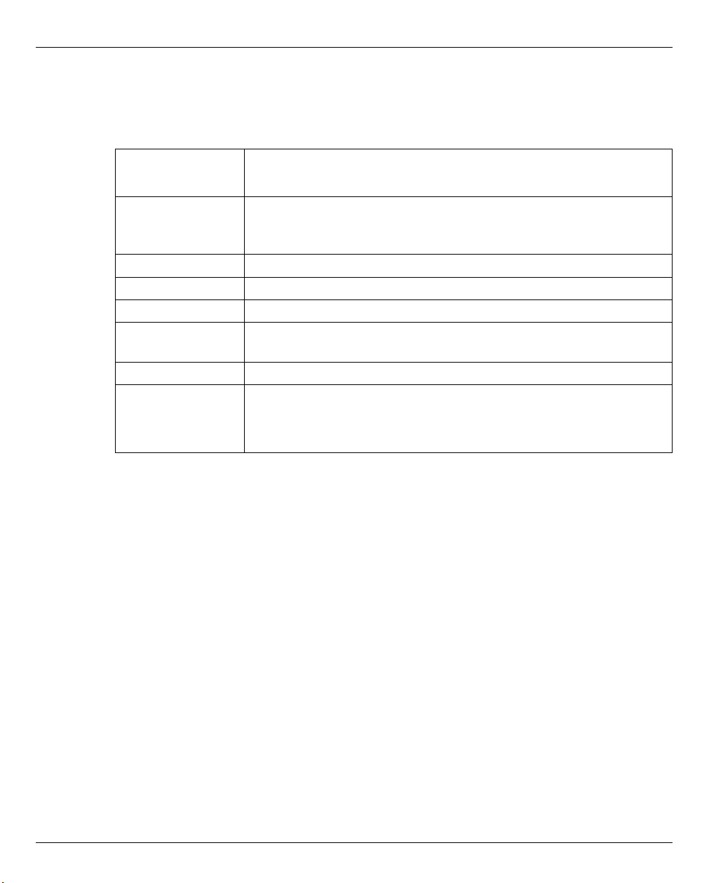
In the maximum configuration, a FUJITSU Server BS2000 of the SE Series (SE server for
short) consists of the following components:
● Management Unit (MU) with SE Manager
The operation of the SE server with a single Management Unit is called a "single-MU
configuration". The Management Unit can be redundant in design. An SE server
configuration with more than one Management Unit (MU redundancy on the SE server
or Management Cluster with two SE servers) is called "multi-MU configuration".
MU redundancy ensures that the components of the SE server can still be operated if
one MU fails. In particular this means that the SKP functionality is then still available for
operating an SU /390.
● Server Unit (SU)
– An SU /390 enables operation of BS2000 (Native BS2000 or VM2000).
– An SU x86 enables operation of BS2000 (Native BS2000 or VM2000). XenVM
operation with Linux or Windows guest systems is also possible as an option.
Depending on the model family, the following combinations are possible:
– SE700 with an SU /390 and optionally up to two further SU x86
– SE500 with an SU /390 and optionally up to two further SU x86
– SE300 with an SU x86 and optionally up to two further SU x86
● Application Unit (AU)
Multiple AUs can be operated on the SE server. An AU enables operation of
applications under Linux, Windows or hypervisor-based systems.
A distinction is made between AUs depending on the hardware base:
● Application Unit PY refers to all PRIMERGY-based AUs (e.g. hardware model AU25
or AU47).
● Application Unit PQ refers to all PRIMEQUEST-based AU (e.g. hardware model
AU87 or DBU87).
U41855-J-Z125-3-76 21
Page 24

Architecture Architecture and strategies
● Net Unit (NU)
The Net Unit offers maximum performance and security for internal communication in
an SE server and for a connection to customer networks (IP networks). For an SU /390,
HNC is an additional component of the Net Unit.
In the case of SE500 and SE700 the Net Unit is always redundant in design. In the case
of SE300 redundancy of the Net Unit is optional.
The Net Unit is supplied preconfigured, is autonomous with respect to SE server
management, and can easily be connected to the customer network.
● Rack console and KVM switch
● Peripherals (storage)
● Optional hardware components:
Disk storage systems (for SU x86, AU), tape library systems (for SU x86), FC switches
22 U41855-J-Z125-3-76
Page 25
Architecture and strategies Architecture
Redundant Management Unit (MU) with SE Manager
Customer network
Net Unit
SE Server
(IP networks)
Management Unit (MU) with SE Manager
Redundant Net Unit
BS2000
Linux
Windows
Disk
Tape
Disk
VMware, Citrix,
Hyper-V, OVM ...
Further optional
peripherals
VM2000
Xen
VM2000
Windows
Linux
BS2000
BS2000
Peripherals
Application
Server Unit x86Server Unit /390
Unit (AU)
(SU /390) (SU x86)
All components of the SE server are integrated into a joint rack or multiple racks.
Information on the current hardware configuration of your SE server is displayed by the
SE Manager in the Hardware → HW Inventory menu (see section “HW inventory” on
page 285).
Figure 1: Architecture of SE servers
The SE Manager enables you to operate and manage all components of the SE server
centrally from the Management Unit. The SE Manager offers a user-friendly, web-based
user interface for this purpose.
U41855-J-Z125-3-76 23
Page 26

Software of the SE server Architecture and strategies
2.2 Software of the SE server
2.2.1 Structure of the software
M2000
M2000 is the basic software of the Management Unit. It provides, among other things, the
following main functions for accessing SE servers:
● SE Manager as Single Point of Administration (central operation and administration of
the SE servers)
– Operation and administration of the BS2000 systems on SU /390 and SU x86
(BS2000 console, BS2000 dialog, SVP console on SU /390)
– Operation and administration of the XenVMs on SU x86
– Operation and administration of VMs on AUs
– Realizes the data collection and storage necessary for managing and operating the
SE server.
Receives events from all instances of the SE server for displaying, editing and
forwarding.
In the case of a multi-MU configuration, these internal functions are coordinated
between the MUs.
● Role and user strategy
● Net Unit functions for integration of the SE server into the network world
● SE Desktop for operation on the local console of the Management Unit
● Integration into the Remote Service
X2000
X2000 is the basic software of the SU x86. It provides, among other things, the following
functions:
● Execution system for BS2000 systems and XenVMs (including I/O system)
● Management functions for administering the BS2000 VMs and the XenVMs in the SE
Manager
● Management functions for administering the BS2000 devices and the XenVM devices
in the SE Manager
● Configuration of the Net-Storage for the BS2000 systems of the SU x86
24 U41855-J-Z125-3-76
Page 27
Architecture and strategies Software of the SE server
HNC
HNC is the basic software of the HNC. It provides, among other things, the following
functions:
● Network connection for the BS2000 systems of the SU /390
● Configuration of the Net-Storage for the BS2000 systems of the SU /390
Add-on packs
In addition to the standard software M2000, X2000, and HNC, the SE server offers
enhancements by means of add-on packs.
The possible installation of add-on packs on the MU enables costs and maintenance to be
avoided on the SE server for additional servers, e.g. for ROBAR or openSM2. See also
section “Add-on pack” on page 27.
2.2.2 Software status, system version and update status
In addition to the system version, the software status also includes the updates which are
installed on the unit. Software updates can only be installed if they are available on the local
system.
Under SW version in the system information the SE Manager displays on the MU, SU x86,
and HNC the version of the basic software M2000, X2000 or HNC, including the update
status.
On the SU /390 the SE Manager displays the HCP (Hardware Control Program) software
(e.g. in the SU /390 information on page 201), but in this case does not support update
management.
The software status consequently has the following components:
Component Example Description
Version 6.2A
Revision REV=0100 Update status
Security fix 6.2A, No.001 – Security fixes are assigned to a version and update
status.
– Security fixes have a sequence number for each
version status and each update status (001 in the
example)
Hot fix 6.2A, REV=0100,
A0603507-H03
U41855-J-Z125-3-76 25
– Hot fixes are assigned to a version and update status
– In their name hot fixes contain a problem message
number (A0603507 in the example) and a sequence
number (H03 in the example)
Page 28

Software of the SE server Architecture and strategies
In contrast to the other update types, add-on packs are autonomous software products
which FUJITSU makes available for installation on the Management Units. An add-on pack
is either a software product which is installed by default (e.g. StorMan on the Management
Unit) or one which is optional.
Add-on packs are managed like updates to the basic software, but the software status
displayed consists of the product name and a product-specific version designation.
2.2.3 Updates to the basic software and add-on packs
You can transfer the following types of updates to the Management Unit, the SU x86 and
the HNC and manage them there:
– Security fix
– Hot fix
– Add-on pack
2.2.3.1 Naming conventions
Updates are supplied as files of the following types:
● iso.gz for files which can be downloaded from the download server
● iso for files which are supplied on CD/DVD
The following naming conventions apply for the files containing the updates:
Security fix e.g. MV6.2A.SF.001.iso[.gz]
The security fix with the number 001 is assigned to the version and update status
6.2A.
Hot fix e.g. MV6.2A0100.A0603507-H03.iso[.gz]
The hot fix with the name A0603507-H03 is assigned to the version and update
status 6.2A REV=0100.
Add-on pack e.g. MV.STORMAN-7.0.0-12.4.iso
This add-on pack contains StorMan V7.0
The first letter in the file name indicates the basic software of the associated unit:
– X for X2000 on the Server Unit
– M for M2000 on the Management Unit
– H for HNC on the HNC
26 U41855-J-Z125-3-76
Page 29

Architecture and strategies Software of the SE server
2.2.3.2 Security fix
A security fix contains all the security-relevant updates for the Linux-based basic software.
Security fixes protect the system against, for example, unauthorized intrusion and attacks
from the outside. Whether you install current security fixes depends on your security
requirements and whether the SE server can be accessed only via the protected
administration LAN or also from the outside. The functional use of the SE server is also
guaranteed without the current security fixes.
A security fix may also be installed by the customer. Installation takes place in the SE
Manager under an administrator account.
2.2.3.3 Hot fix
A hot fix contains a patch with which an urgent problem in your system can be rectified as
quickly as possible.
A hot fix can only be installed by Customer Support. Installation can only be performed
using a CLI command under the Customer Support account.
2.2.3.4 Add-on pack
Add-on packs are software components on a unit which have their own web interfaces that
are integrated into the SE Manager. The type and location of the integration into the SE
Manager depends on the category to which the add-on pack is to be assigned, e.g.
Application, Monitoring, Hardware Management.
Add-on packs have their own version schema and can be replaced independently of the
basic software.
An add-on package contains software which FUJITSU provides for use on the units.
Currently add-on packs are only provided for the Management Unit. By default a distinction
is made between installed and optional add-on packs:
– In the case of an add-on pack which is installed by default, the customer must, if
necessary, install newer versions.
– In the case of an optional add-on pack, the customer must also perform installation or
uninstallation. Customer Support can also do this when requested.
Add-on packs are also distinguished by whether they are chargeable or included in the price
and preinstalled.
U41855-J-Z125-3-76 27
Page 30

Software of the SE server Architecture and strategies
The fact that the web interfaces of the add-on packs are integrated into the SE Manager
means the following:
– The add-on packs are visible as links in the SE Manager's menu.
– When such a link is clicked, the add-on pack's web interface is opened in the same
browser window.
– You log into the add-on pack's web interface implicitly using the account with which you
are working in the SE Manager and in the same session. The same setting therefore
applies for the session timeout in the event of inactivity. Logging off in the add-on also
leads to logging off in the SE Manager and thus to the login window of the SE Manager.
– From the add-on pack's web interface there is a link back to the last valid main window
in the SE Manager.
Add-on packs have their own online help systems and, when necessary, are described in
separate product manuals. These online helps are integrated into that of the SE Manager,
but can also be called separately.
Overview of the current add-on packs in the SE Manager on the MU:
Add-on
(product name)
OPENSM2
(openSM2 Performance Monitor)
OPENUTM
(openUTM Server Administration)
ROBAR
(ROBAR-SV Server)
STORMAN
(Storage Manager)
Table 1: Add-on packs in the SE Manager on the MU
ChargeablePreinstalled
Yes Optional Category: Monitoring
Yes No Category: Application
Yes Optional Category: Application
No Yes Category: Hardware
ex works
Integration into the
SE Manager
→ Performance
→ Applications → SE management
application
→ Applications → SE management
application
Management
→ Hardware → Storage
28 U41855-J-Z125-3-76
Page 31

Architecture and strategies Software of the SE server
If there is more than one MU (MU redundancy or Management Cluster):
● Every add-on pack can be installed on any MU or on all MUs.
The recommended use and configuration for multi-installation can be found in the
documentation for the add-on.
● All installed add-on packs are integrated into the SE Manager with an MU-specific link.
Example
U41855-J-Z125-3-76 29
Page 32

Software of the SE server Architecture and strategies
2.2.4 Management applications
Management applications have graphical interfaces which can be reached via the web and
operated using the browser.
A distinction is made between SE management applications and user-defined
management applications.
● SE management applications execute on the Management Units and are fully
integrated into the SE Manager. They are implemented as a permanent part of the SE
Manager or as add-on packs (see “Add-on pack” on page 27).
The following SE management applications are currently available:
– BS2000 Backup Monitor
The BS2000 Backup Monitor is a permanent part of the SE Manager.
– Storage Manager
StorMan is implemented as a preinstalled add-on pack.
– openSM2
openSM2 is implemented as an optional add-on pack.
– openUTM WebAdmin
openUTM WebAdmin is implemented as an optional add-on pack.
– ROBAR (ROBAR-SV Server)
ROBAR is implemented as an optional add-on pack.
● User-defined management applications are applications which support integration into
the SE infrastructure. When you click a user-defined management application, it is
opened in a new browser window.
See also section “Managing user-defined management applications” on page 161.
i In contrast to this, "user-defined links" are only links to arbitrary internet pages
or links to web-based applications which execute on systems of the SE server.
When it is clicked, a user-defined link is opened in a new browser window.
See also section “Administering user-defined links” on page 162.
30 U41855-J-Z125-3-76
Page 33

Architecture and strategies Networks
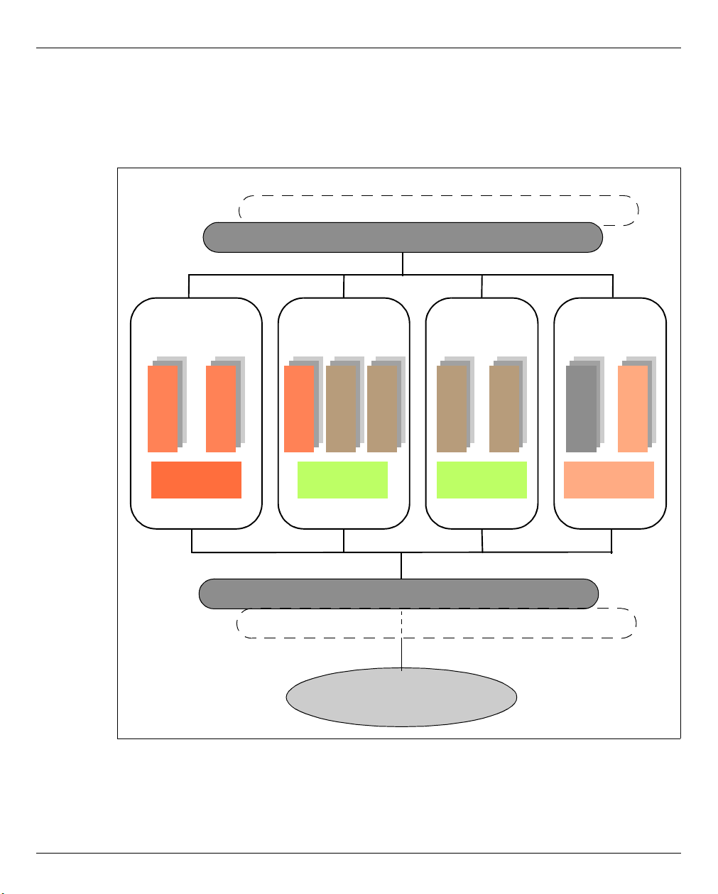
2.3 Networks
The Net Unit supplies the central link of all the SE server's IP network connections. It
concentrates the network connections of the various Server Units to the outside into the
customer network (public networks) and, internally, establishes the network connections
between the various Server Units (private networks).
The hardware of the Net Unit is supplied preconfigured. All the cable connections to the
Server Units are implemented professionally in the cabinet in the factory. Connections to
the customer networks (data networks, management networks) only need to be established
to the reserved connection ports of the Net Unit (uplinks). In terms of the software the Net
Unit is fully installed and immediately ready to operate.
Up to two uplinks are possible per public network to provide the connection to the
customer's LAN structure. The uplinks are provided without vendor dependencies and can
be connected to any switch (managed or unmanaged). The uplinks are operated without a
VLAN ID (i.e. untagged), and no switch protocol (e.g. spanning tree) is used.
Only the relevant configuration measures need to be implemented in the operating systems
to use the networks. It is not necessary to involve network administrators of the customer
network.
Private networks have been configured for the Sever Units to communicate with each other.
These separate the network communication within the SEs totally from the customer
network. The private networks are protected from each other and can be configured flexibly
according to customer requirements. Network security is automatically enhanced because
of this protection and the flexibility to configure and operate private networks independently
of the customer infrastructure.
The private networks can be operated with high performance, do not influence the customer
network, and cannot be influenced by it (e.g. they continue to function even when the
customer infrastructure fails).
The Net Unit can be designed with redundancy in the interest of protection against failure.
By default, SE700 and SE500 incorporate a redundant Net Unit. Redundancy can be
ordered as an option for SE300.
The BS2000 systems communicate with the MU over a private network, see section
“Integration of BS2000 into the SE Manager” on page 36.
U41855-J-Z125-3-76 31
Page 34

Networks Architecture and strategies
The following logical networks are supported:
– Data Network Public
– Data Network Public (DANPU): when required, up to 8 additive networks
DANPU<n> (where <n>= 01..08) can be configured for connecting applications to
the public customer network.
– Data Network Private
– Data Network Private (DANPR): when required, up to 99 networks DANPR<n>
(where <n>= 01..99) can be configured for internal private customer networks for
SE servers.
– Public management networks
– Management Admin Network Public (MANPU) for administrative access to the MU,
BS2000 systems and AUs
– Management Optional Network Public (MONPU): the additive administration
network can be configured when required (e.g. when AIS Connect is not to be
operated via MANPU but over a separate network).
– Management Network Private
– Management Control Network Local (MCNLO) for the local SE server
communication
– Management Control Network Private (MCNPR) for SE server communication
– Management Optional Network Private (MONPR): when required, up to 8 additive
networks MONPR<n> (where <n>= 01..08) can be configured for SE server
communication.
– Management SVP Network Private (MSNPR) enables SVP communication to the
SU /390 on SE700/SE500
In addition to the connections of the units to the switches of the Net Unit, direct cabling from
the units to the customer network can also be used.
The SE Manager provides a graphical display of the network topology with all the network
components and connections of the SE server in the Topology tab of the Hardware → IP
networks menu. See section “Graphical display of the internal IP network topology” on
page 257.
32 U41855-J-Z125-3-76
Page 35

Architecture and strategies Networks
Figure 2: Block diagram of the Net Unit
2.3.1 Services
2.3.1.1 IPv6 autoconfiguration
IPv6 autoconfiguration based on the "radvd" (Router Advertisement Daemon) which runs
on the MU is provided for communication in the MCNPR network segment. Optionally IPv6
autoconfiguration is also provided for the private network segments MONPR and DANPR.
The prefix "fd5e:5e5e:<vlan-id>:0::/64" (for MCNPR where vlan-id 600 =
fd5e:5e5e:600:0::/64) is preconfigured. When conflicts occur on the customer side,
Customer Support can set a different prefix (change the first 32 bits of the prefix).
Connected units (with enabled IPv6 autoconfiguration) are then assigned an IPv6 address
based on the MAC address (e.g. fd5e:5e5e:600:0:219:99ff:fee2:79d/64).
IPv6 autoconfiguration is automatically enabled for MCNPR by means of the installation
and is required for the management functions for the units. IPv6 autoconfiguration can
optionally be activated for private network segments.
Each MU is assigned its own static IPv6 address during configuration in MCNPR (e.g.
fd5e:5e5e:600::101/64 = IPv6 prefix + suffix <mu-id>0<se-id>) with which the MU in the
network segment can be addressed.
U41855-J-Z125-3-76 33
Page 36

Networks Architecture and strategies
2.3.1.2 Domain Name System (DNS)
A DNS server for the "senet" domain which provides name resolution for communication
runs on the MU. The DNS server is configured in such a manner that it performs name
resolutions for "senet" itself and forwards other name resolutions to external DNS servers
which must be configured manually.
The static IPv6 address of the local MU is the first name server in the DNS configuration of
the MU. Two further external DNS servers and the external domain search list can be
configured.
The IPv6 addresses of the two possible MUs are preconfigured on an SU x86 or HNC. No
further configuration is required.
DNS queries are thus directed to the MU via the network segment MCNPR. The MU then
either resolves the address itself for the "senet" domain or forwards the request to the
customer's external DNS servers.
Name resolutions can also be used for the other network segments MONPR and DANPR.
For this purpose the relevant network segments must be configured on the MU in the SE
Manager, and IPv6 autoconfiguration must be enabled (see section “Managing the IP
configuration” on page 208).
2.3.1.3 Managing the "senet" domain
You manage the names and aliases of the "senet" domain in the SE Manager. You can add,
modify or delete DNS entries (see section “Configuring SENET” on page 254).
The management of the "senet" domain is global. Changes to SE server configurations with
more than one MU are automatically aligned in the DNS.
34 U41855-J-Z125-3-76
Page 37

Architecture and strategies Networks
The aliases are assigned according to the following schema:
Component MCNPR SE alias
(x=1..n; y=1..8; z=01..99)
MU mu<x>-se<y>.senet M2000
SU /390 su0bs2-se<y>.senet BS2000 (Native/monitor VM)
su0vm<z>-se<y>.senet BS2000 VMs
SU x86 su<x>-se<y>.senet X2000
su<x>irmc-se<y>.senet SU x86 iRMC
su<x>bs2-se<y>.senet BS2000 (Native/monitor VM)
su<x>vm<z>-se<y>.senet BS2000 VMs
Managed Switch nswa<x>-se<y>.senet nswa = 1 Gbit
nswb<x>-se<y>.senet nswb = 10 Gbit
HNC hnc<x>-se<y>.senet HNC
hnc<x>irmc-se<y>.senet HNC iRMC
AU PY au<z>-se<y>.senet System (e.g. VMware)
AU PQ auc<z>-se<y>.senet Management Board of a PRIMEQUEST
auc<z>p<nr>se<y>.senet Partition of a PRIMEQUEST
RAID system prd<z>-se<y>.senet e.g. ETERNUS DX (prd=periphery raid)
Tape library ptl<z>-se<y>.senet e.g. LT40 S2 (ptl=periphery tape library)
Other periphery pot<z>-se<y>.senet (pot=periphery other)
ROBAR rob<z>-se<y>.senet ROBAR controller
Table 2: Name schema of the SE aliases
Description
2.3.1.4 ACL functionality
You can lock or release individual TCP/UDP ports (services) for the DANPU<xx>, MANPU,
MONPU, DANPR<xx>, and MONPR<xx> networks in an ACL (Access Control List):
– Either the administrator defines an ACL list of the type "permit" in which all released
services (ports) are explicitly entered.
i After the ACL of the type "permit" has been configured, the list is initially
empty. Access to the network is thus locked for all services (ports).
– Or the administrator defines an ACL list of the type "deny" in which all the locked
services (ports) are explicitly entered.
One ACL list each can be defined for IPv4 and IPv6.
U41855-J-Z125-3-76 35
Page 38

Networks Architecture and strategies
2.3.1.5 NTP server
The MU of the SE server is configured as an NTP server and is used as the central NTP
server for the SE server.
The units SU x86 and HNC are configured in such a manner that time synchronization takes
place from the local SE server's MU.
In the case of MU redundancy, both MUs of the local SE server are configured as timers.
If external timers are used in a multi-MU configuration, the same external NTP servers must
be configured on each MU, so that the time remains accurate even if one MU is switched
off.
The static IPv6 address of the MU can be used for time synchronization of an AU with the
local SE server's MU.
For further details, see section “Time synchronization” on page 65.
2.3.2 Integration of BS2000 into the SE Manager
The VM Management for SU /390 in VM2000 operation mode requires communication
between the monitor system and the MU. The BS2000 Backup Monitor also requires
communication between the BS2000 systems on which the backup requests take place and
the MU.
The communication uses the internal network MCNPR (see figure 2 on page 33) and must
be configured as follows:
● In the BS2000 systems mentioned a suitable BCAM configuration must be configured
by means of the templates provided. See also the BCAM manual [13].
● The REWAS subsystem must be active (default).
36 U41855-J-Z125-3-76
Page 39

Architecture and strategies Networks
2.3.3 Integration of BS2000 into the LAN
From the viewpoint of BS2000 devices, the ZASLAN, LOCLAN and BRGLAN are devices
which are used for the LAN connection to the external physical network or for internal
communication in the Server Unit. They can be created in the SE Manager (see section
“Managing LAN devices” on page 179) and must, in the case of VM2000, then be assigned
to the BS2000 VM concerned.
BS2000 ZASLAN
In the case of a ZASLAN connection, BS2000 uses a LAN interface of its own (Ethernet
controller) independently of other LAN interfaces. Only via such a connection does BS2000
obtain a direct view of the physical network.
In VM2000 mode a LAN interface can be used jointly by all connected BS2000 guest
systems. To permit this, a separate ZASLAN connection is configured for each BS2000 VM.
The associated devices are connected to their particular VM (using the ADD-VM-DEVICES
command).
The ZASLAN interfaces are displayed or modified in the SE Manager using Devices
[<se server>(SE<model>) →] <unit> (SU<model>)
→ BS2000 devices on the LAN tab.
→
I All PCI ports can be used for the ZASLAN connections.
The following must be observed on the SU x86: LAN interfaces cannot be used
simultaneously for ZASLAN and virtual switches of XenVMs (see section
“Integration of the XenVM guest systems into the LAN (only SU x86)” on page 39).
LOCLAN
The local LAN is a network implemented by software in the Linux-based basic system
concerned (X2000/M2000/HNC). The local LAN connections are consequently not included
in the figure illustrating the LAN structure (see figure 2). The connection of BS2000 to the
local LAN is implemented on an SU x86 system with connections implemented by software
(MANLO: Management Network LOCLAN), and on an SU /390 by FC connections between
SU /390 and MU (MANLO) or HNC.
The following addresses are preconfigured for BS2000 and the basic system
(X2000/M2000):
System IP address
Basic system 192.168.138.12
BS2000 (Native or monitor system) 192.168.138.21
BS2000 guest systems on other VMs 192.168.138.22 etc.
U41855-J-Z125-3-76 37
Page 40

Networks Architecture and strategies
A second MU (in case of SU /390) is automatically assigned the addresses 192.168.139.x.
If address conflicts occur, the Customer Support can configure other address ranges.
BRGLAN (only SU x86)
A BRGLAN connection connects BS2000 with an internal virtual switch and enables a LAN
connection to the other virtual machines (= Xen Linux or Windows guest systems) which
are also connected to the same virtual switch.
A BRGLAN connection is required to implement one of the following connections:
– The Native BS2000 system for the XenVMs on the same virtual switch
– BS2000 VMs for XenVMs on the same virtual switch
I If only BS2000 VMs communicate with each other, LOCLAN connections
should be used.
The BRGLAN connection is a protected internal connection in the Server Unit which is
implemented in the software and thus does not occupy any slots.
With BRGLAN the packet size can be up to 1500 bytes.
An internal virtual switch is configured using the SE Manager. A separate BRGLAN
connection is configured in X2000 for each VM with a BS2000 guest system. The
associated devices are assigned to the relevant VM.
I The BRGLAN connection requires that at least one virtual switch exists. Virtual
switches can be configured only in conjunction with the operation of XenVMs, i.e. a
XenVM license must exist. For details, see “Integration of the XenVM guest
systems into the LAN (only SU x86)” on page 39.
BRGLAN connections are virtual network connections and are therefore not displayed in
the physical LAN structure (see figure 2).
38 U41855-J-Z125-3-76
Page 41

Architecture and strategies Networks
2.3.4 Integration of the XenVM guest systems into the LAN (only SU x86)
The Linux/Windows systems on the XenVMs communicate with each other or with external
systems via software instances which are known as virtual switches (or vSwitches for
short). Virtual switches are made available as XenVM devices. A XenVM is connected
either when the XenVM is created or at a later point in time by assigning a virtual Network
Interface Card to the vSwitch.
Depending on the connection type provided, a distinction is made between two types of
vSwitches:
● Internal vSwitch
An internal vSwitch enables the XenVMs connected to it to use a communication
connection which is protected locally. Internal vSwitches can also be used by the
BS2000 Native system and by BS2000 VMs (see “BRGLAN (only SU x86)” on
page 38).
● External vSwitch
An external vSwitch uses a LAN interface which permits an external LAN connection.
All XenVMs connected to this vSwitch use this connection to communicate with external
systems.
If more than one unused LAN interface is available, an external vSwitch can also use
two LAN interfaces. In this case, the XenVM connection is configured with redundancy
(also referred to as "bonding").
The virtual switches and their current assignment to XenVMs are displayed in the SE
Manager by selecting Devices
devices on the Virtual switches tab. New virtual switches can be created there and unused
switches can be deleted.
→ [<se server>(SE<model>) →] <unit> (SU<x86>)→ XenVM
I Only PCI ports can be used for the external vSwitches.
LAN interfaces (PCI ports) cannot be used more than once (e.g. for multiple virtual
switches or for a virtual switch and a ZASLAN).
U41855-J-Z125-3-76 39
Page 42

Networks Architecture and strategies
2.3.5 Overview of the possible LAN connections of the VMs
LOCLAN1
ZASLAN
Monitor system
(BS2000)
Guest system
(BS2000)
SU/390
LOCLAN2LOCLAN2
Net Unit | direct connection
MU HNC
Base system
(X2000)
LOCLAN
BRGLAN (on internal virtual switch)
LAN on external
ZASLAN
eth<n>eth<l>eth<k>
Monitor system
(BS2000)
Guest system
(BS2000)
Guest system
(Windows/Linux)
Guest system
(Windows/Linux)
Internal
LANs
External
LANs
eth<m>
virtual switch
The figures below provide an overview of the possible internal and external LAN
connections of the VMs running on the Server Unit (BS2000 on SU /390 or BS2000 and
XenVM on SU x86). Physical network integration is shown in figure 2.
Figure 3: Overview of possible internal and external LAN connections (Server Unit /390)
Figure 4: Overview of possible internal and external LAN connections (Server Unit x86)
40 U41855-J-Z125-3-76
Page 43

Architecture and strategies Networks
2.3.6 Important information about IP configuration
After your SE server has been installed, the IPv6 protocol is enabled throughout the system.
Use of IPv6 for all networks of the SE server is enabled by default. You can perform the
following configuration measures separately on a network-specific basis:
● When the IPv6 protocol is enabled throughout the system, you can enable or disable
the use of IPv6 for specific networks.
IPv6 is permanently set for the internal network (MCNPR).
● Enable/disable Autoconf (Stateless Address Autoconfiguration)
This setting is evaluated only when IPv6 is enabled:
Autoconf is a user-friendly automatic procedure which enables the system to specify its
own LAN addresses on the basis of information which is provided both locally and
remotely. Autoconf requires a router which is responsible in the network that, when
requested by the system, assigns the so-called IPv6 prefixes (one prefix per available
network).
The system supplements these prefixes for each LAN interface to make them
unambiguous addresses, the supplement being based by default on the MAC address
of the LAN interface concerned.
A LAN interface configured in this way is automatically linked to all available networks.
In contrast to Autoconf, in the case of DHCP IPv6 address assignment (stateful) is
performed by an instance in the network which also manages the current state of the
address assignment.
● Enable/disable DHCPv6
DHCPv6 requires a DHCP server in the network which distributes IPv6 addresses.
● Enable/disable DHCPv4
DHCPv4 requires a DHCP server in the network which distributes IPv4 addresses.
In all cases of dynamic address distribution, the addresses assigned are provided with
Validity times by the Autoconf router or the DHCP server.
Any number of IPv6 addresses (and also IPv4 addresses) can be allocated explicitly.
When IPv6 is used, IPv6 routes can also be configured.
U41855-J-Z125-3-76 41
Page 44

External configuration disks Architecture and strategies
2.4 External configuration disks
On a configuration disk of a unit (MU, SU x86, HNC), the following data of the SE server
configuration are stored:
● General data of the SE server:
– Model, name and location
– Cross-unit data
● Unit-specific data with contents that should remain available even after the Unit fails or
is powered off (not for HNC):
– Model, SW version and host name
– IP configuration
– FC configuration
– VM data for BS2000 (on SU x86 also for Linux and Windows)
● Current configuration of the Net Unit switches
By default, the data are locally stored on an internally mirrored disk of the Unit (MU, SU x86,
HNC).
In addition to the internal configuration disk, up to two external configuration disks can be
configured on external FC RAID systems, to which all MUs and SU x86 have access via a
redundant connection.
This ensures consistency: Every MU and SU x86 reads the data of the SE server in the
same way and the actions on these units can be coordinated.
The SE Manager displays information about the configuration disks, e.g. of an MU, in the
Hardware → Units[ → <se server> (SE<model>)] → <unit> (MU) → Information menu (see
“Displaying configuration disks of the MU” on page 207):
Figure 5: MU with external configuration disks
42 U41855-J-Z125-3-76
Page 45

Architecture and strategies External configuration disks
External configuration disks are required in the following cases:
● MU redundancy
– On SE700/SE500, external configuration disks are mandatory.
– On SE300, using them is recommended to avoid restrictions when working with the
SE Manager (see below).
● Cluster
For the SE Cluster (Management Cluster), external configuration disks are sufficient on
the MUs. For SU Clusters, external configuration disks are also required on SU x86.
MU redundancy for SE300 – Restrictions for operation without external configuration
disks
In case the customer is unable to provide external configuration disks, working with the SE
Manager is still possible but subject to certain restrictions:
● Session management
– Customer Support has to specify the SEM setting "Working with MU-local sessions"
on both MUs.
– As soon as a function is called on the other MU (upload/download dialog for the
other MU, link in the header), the user is redirected to the corresponding main
window of that MU. You have to log in on that MU.
● Management of global, i.e. cross-MU, data
In this case, these kinds of data only seem to be global. They are actually local data that
have to be managed separately on each MU:
– Accounts, LDAP, IP based access rights
– Applications and Application Units
● The data collection is not coordinated between the two MUs and therefore a different
status of the data may be displayed on each MU.
U41855-J-Z125-3-76 43
Page 46

Cluster Architecture and strategies
2.5 Cluster
Redundant MU
SE Server SE1
SAN
Management Unit (MU)
Net Unit
Redundant Net Unit
SU x86
SU /390
AU
Redundant MU
Management Unit (MU)
Net Unit
Redundant Net Unit
SU x86
SU /390
AU
SE Server SE2
ISL-E
ETERNUS
DX
ETERNUS
DX
External configuration disk
Two types of clusters are possible in an SE server configuration.
2.5.1 Management Cluster
If two SE servers are combined into one Management Unit, it is called a "Management
Cluster" (or "SE Cluster").
A Management Cluster is configured by Customer Support based on the customer's wishes
and is used to operate und administrate the two SE servers together.
A Net Unit connection between the two SE servers (ISL-E) and one or two external
configuration disks for managing the global data are required to establish a Management
Cluster.
See also section “External configuration disks” on page 42.
Figure 6: Management Cluster with two SE servers
44 U41855-J-Z125-3-76
Page 47

Architecture and strategies Cluster
Regarding administration and operation, all MUs of the Management Cluster are equally
ranking. This means you can centrally administer and operate all objects of the whole SE
server configuration (in this case: two SE servers) from one MU.
The SE servers can be operated as long as one MU functions. However, an MU of the local
SE server is required for the SVP operation of an SU /390 and its correct HW display.
2.5.2 SU Cluster
Two Server Units of the same type (SU /390 or SU x86) can be combined into a logical unit,
a so-called "SU Cluster".
An SU Cluster is configured by Customer Support based on the customer's wishes and
provides the Live Migration (LM) function for the BS2000 systems of the two Server Units.
Live Migration is used to migrate a BS2000 system from the source SU to another SU
(target SU) of the same type and operating mode. This means that a running system can
be migrated to a target SU without interruption. A planned operational interruption, e.g. for
hardware maintenance, is therefore no longer required. LM can also be used for manual
load balancing, e.g. in the event of recurring high-load phases.
An SU Cluster with SU /390 is always cross-server and thus requires a Management
Cluster. An SU Cluster with SU x86 may also be configured locally on one server, in case
an SE server has more than one SU x86.
U41855-J-Z125-3-76 45
Page 48

Cluster Architecture and strategies
ETERNUS
DX
Redundant MU
SE Server SE1
SAN
Management Unit (MU)
Net Unit
Redundant Net Unit
SU x86
SU /390
AU
Redundant MU
Management Unit (MU)
Net Unit
Redundant Net Unit
SU x86
SU /390
AU
SE Server SE2
ETERNUS
DX
SU Cluster x86
SU Cluster /390
ISL-E
External configuration disk
Figure 7: SU Cluster in the Management Cluster with two SE servers
The Live Migration action can be called from the "Operation" main window of the respective
BS2000 system. It is only available on SUs that are part of an SU Cluster. Whether or not
an LM is possible, depends on the current cluster status. The current status is displayed by
the SE Manager in the Cluster → <cluster-name> → SU Cluster menu, see section “Managing
an SU Cluster” on page 297.
LM requires both SUs to have the same operating mode. In case of an SU /390, LM is only
possible if the current operating mode is set to VM2000 mode.
In order to avoid unwanted fault indications and events over long periods when
maintenance takes place (e.g. SU switched off or in error status), the SU Cluster can be
temporarily deactivated in the Cluster → <cluster-name> → SU Cluster menu. LM is not
possible in this state as well.
Details on the use of clusters are described in the Whitepaper „Cluster Solutions for SE
Servers“ [8].
46 U41855-J-Z125-3-76
Page 49

Architecture and strategies Management Unit and SE Manager
2.6 Management Unit and SE Manager
The Management Unit together with the SE Manager enables central monitoring,
administration and operation of all units of the SE server and the systems running on it.
Additional cross-unit functions are also available, e.g. for displaying the components of the
SE server, together with the operating status or performance monitoring.
2.6.1 Role and user strategy
Depending on how the system is viewed, different tasks must be performed to administer
and operate the SE server which are categorized in multiple task areas. The task areas
correspond to the roles described below.
● Administrator
● BS2000 administrator
● XenVM administrator
● AU administrator
● Operator
● Service
The roles are tied to an account. In other words the user takes over a role when he/she logs
in on the SE Manager with an account which is assigned to this role. A user who takes over
a task area (i.e. a role) must be authorized to execute all the functions which are required
to perform these tasks.
When the system is delivered, there are predefined accounts for the Administrator and
Service roles, see “Predefined accounts” on page 50.
All roles except the Service role can be assigned to additional accounts, see “Further
accounts with role assignment” on page 50.
The task areas of the various roles are described in detail below. For further information,
see the online help.
U41855-J-Z125-3-76 47
Page 50

Management Unit and SE Manager Architecture and strategies
Administrator
This task area comprises management of all units on the SE server and management and
operation of the systems which run on Server Units and Application Units of the SE server.
– BS2000 systems:
For BS2000 on a Server Unit, the task area comprises operation of the BS2000 system
or, under VM2000, operation and partial management of the BS2000 guest systems.
– XenVM systems:
For a Server Unit x86 with a XenVM license the task area also comprises management
of the virtual machines (XenVMs) and their devices for Linux and Windows guest
systems.
– Application Units:
For the optional Application Units the task area comprises the configuration and
management of the Application Units and the systems running on these.
In the SE server configuration, the administrator performs, among others, the following
tasks:
– Managing all user accounts
– Managing individual authorizations
– LDAP configuration
– Managing the networks
– Monitoring audit and event logging
– The administrator can configure the automatic messaging (via SNMP trap or E-Mail)
that is triggered for events with a certain weighting.
– Additional general configurations like installing add-on packs, etc.
The administrator can also open a Linux shell on the Management Unit and can use this to
call CLI commands. The cli_info command lists the M2000-specific commands which
are available. You can obtain a detailed description of the commands in the online help.
All administrator accounts are of equal value.
48 U41855-J-Z125-3-76
Page 51

Architecture and strategies Management Unit and SE Manager
BS2000 administrator
Comprises (largely) the subset of the Administrator task area which refers to BS2000
systems.
All BS2000 administrator accounts are equal ranking.
General access to the Linux shell is not possible. A BS2000 administrator can, however,
access the BS2000 console, the BS2000 dialog and the SVP console outside the SE
Manager by means of ssh client PuTTY. To do this, they can execute the bs2Console,
bs2Dialog and svpConsole commands as remote commands by means of PuTTY.
XenVM administrator
Comprises (largely) the subset of the Administrator task area which refers to XenVM
systems.
All XenVM administrator accounts are equal ranking.
Access to the Linux shell is not possible.
AU administrator
Comprises (largely) the subset of the Administrator task area which refers to Application
Units.
All AU administrator accounts are of equal value.
Access to the Linux shell is not possible.
Operator
This task area is a subset of the administrator tasks and largely consists of operating the
BS2000 systems for ongoing operation or, under VM2000, operation and partial
management of the BS2000 guest systems.
All operator accounts are initially equivalent. The administrator can equip them with
individual authorizations for accessing BS2000 or the individual BS2000 VMs.
General access to the Linux shell is not possible. An operator can, however, access the
BS2000 console, the BS2000 dialog and the SVP console outside the SE Manager by
means of ssh client PuTTY. To do this, they can - depending on the individual rights execute the bs2Console, bs2Dialog and svpConsole commands as remote commands by
means of PuTTY.
U41855-J-Z125-3-76 49
Page 52

Management Unit and SE Manager Architecture and strategies
Service
This role includes all tasks of Customer Support, such as maintenance and configuration of
the SE server and registration of Application Units.
Predefined accounts
As supplied, the following local accounts are predefined on the SE server for the existing
roles:
● admin (administrator role)
● service (Customer Support role)
The predefined account admin is protected by an initial password. The administrator can
configure further accounts. Further details are provided in the section “Managing accounts”
on page 300 and in the Security Manual [6].
The predefined account service is available solely to Customer Support. A service account
cannot be administered in the SE Manager.
Accounts of the add-ons do not correspond to a role in the SE Manager and are therefore
not displayed in the SE Manager.
Further accounts with role assignment
The administrator can configure further accounts for an administrator, BS2000
administrator, operator, XenVM administrator or AU administrator. He/She assigns the
Administrator, BS2000 administrator, operator, XenVM administrator or AU administrator role
during configuration. The use of person-related accounts is therefore also possible.
i The accounts are MU-global, i.e. in SE server configurations with more than one
MU, all accounts that are added, changed or removed by the administrator are
implicitly added, changed or removed on all existing MUs.
An account (locally or centrally managed) must always be unique. If an account is
to be added that corresponds to a pre-defined account (e.g. admin, service or
account of an add-on), the SE Manager rejects the action and shows an error
message.
50 U41855-J-Z125-3-76
Page 53

Architecture and strategies Management Unit and SE Manager
Centrally managed accounts
In addition to local accounts, the administrator can also permit LDAP accounts for the
various roles. These accounts are managed centrally on an LDAP server (in particular also
the password).
In order to use LDAP accounts, the access to an LDAP server must be configured. In the
Management Cluster, access to the LDAP server can be configured specifically for one SE
server. See section “Access to an LDAP server” on page 309.
When this requirement is satisfied, the administrator, when creating an account, can
release an LDAP account by means of the account type for the desired role. If the central
account is the same as the existing local account, no LDAP account can be released. When
an LDAP account is removed, it is also locked again.
Accesses to BS2000
All administrator and BS2000 administrator accounts have access authorization to the
BS2000 console and BS2000 dialog of all BS2000 systems.
An administrator can assign these authorizations individually to an operator account, in
VM2000 mode specifically for particular guest systems.
For information on accesses to BS2000 for operator accounts, see section “Managing
individual rights” on page 306.
Accesses to the operating system on XenVMs and Application Units
The customer is responsible for configuring accounts in the operating systems on XenVMs
and Application Units, possibly linked to a strategy for particular roles or authorizations. This
depends on the options of the operating system concerned.
2.6.2 IP-based access to the Management Unit
By default, access to the MUs of the SE server is unrestricted for all IP addresses and
networks. However, the administrator can configure access to the MU (applies for the SE
Manager and CLI) in such a manner that it is possible only for explicitly entered IP
addresses or for IP addresses from explicitly entered IP networks.
In a Management Cluster, the configuration is server-specific.
The current configuration of the access to the MUs is displayed in the IP-based access rights
tab of the Authorizations → Configuration menu (see section “IP-based access restriction to
the MUs” on page 311).
U41855-J-Z125-3-76 51
Page 54

Management Unit and SE Manager Architecture and strategies
2.6.3 Redundant Management Units
Central operation and administration of the SE server is continued after an MU has failed if
there is MU redundancy, i.e. if the SE server has a second MU.
Redundancy of the SKP functionality
On an SE server with SU /390, two MUs mean that the SKP functionality is also provided
with redundancy. As a result, when one MU fails the SU /390 can still be operated via the
SVP.
With respect to the SKP functionality, one MU is always "active" and the other is "passive".
Only the active MU can access the SVP of the SU /390. SVP accesses of the passive MU
take place by means of automatic redirection via the active MU.
On the BS2000 operation mode tab of the SU /390 you see the current status of the MUs with
respect to the SKP functionality. There you can also switch over the passive MU, i.e. the
two MUs change status (see Systems → [<se server>(SE<model>) →] <unit> (SU</390>),
“Switching active Management Unit” on page 109).
The SE Manager displays the current status of the SVP network and of the MU connections
in the IP configuration of the SU /390 (see Hardware → Units[ → <se server> (SE<model>)]
→ <unit> (SU</390>) → Management, “Managing the IP configuration” on page 208).
Operating redundant MUs
When two MUs are available, in other words MU redundancy exists, you can log into the
SE Manager on either of the two MUs. Operation and administration of the SE server is
possible without restriction on either of the two MUs.
In the title bar, the SE Manager displays the existing MUs and permits a "change" to the SE
Manager of the other MU via a link. You do not need to log in again, because, in the default
case, a session on the SE Manager is global. For this, the following requirements must be
met:
– The MUs are registered at an external DNS domain.
– The connection to the SE Manager was made via the DNS name of the MU (entering
the DNS name of the MU as address in the browser).
The MU on whose SE Manager the user is currently logged in is the local MU in this
session, and the other MU is the redundant MU.
52 U41855-J-Z125-3-76
Page 55

Architecture and strategies Management Unit and SE Manager
2.6.4 Central logging
The SE server configuration provides centralized access to the "Audit" and "Event Logging"
functions as well as to the alarm management.
Audit logging logs every action that is executed on a Unit (MU, SU, HNC) of the SE server
configuration via the SE Manager, an add-on or a CLI command. Thus, every administrator
can always see who performed which action with which result and when.
The SE Manager displays all occurring events in the event logging with a timestamp,
weight, name of the reporting unit, name of the reporting component and message text. The
most recent events are displayed first. To provide a better overview, the recent events that
you have not yet seen are also displayed in the Current events tab. The Dashboard displays
a summary of this overview in a separate tile.
The SE Manager displays the audit and event logging entries in the Logging → Audit logging
and Logging → Event logging menu (see “Displaying audit logging” on page 323 and
“Displaying event logging” on page 325).
With the alarm management you can configure automatic SNMP trap or e-mail messages
for events with certain weights; this enables you to recognize important events like error
situations earlier and to react quickly if necessary, even in large SE server configurations.
The SE Manager displays the alarm management configuration in the Logging → Alarm
management menu (see “Alarm management” on page 327).
U41855-J-Z125-3-76 53
Page 56

Virtualization Architecture and strategies
2.7 Virtualization
. . .
. . .
VM2000 hypervisor
VM2000 extensionsHSI offered
VM2000 HSI
Virtual HSI
for VMn
VM2000
monitor
Guest system
VMn
Virtual HSI
for VMm
Guest system
VMm
Virtual HSI
for monitor VM
Monitor system
Monitor VM
2.7.1 Implementing VM2000
Depending on the architecture of the Server Unit there are two fundamentally different
technical implementations of VM2000.
Implementation principle for SU /390
On SU /390 VM2000 controls the hardware of the Server Unit.
The VM2000 monitor manages all VMs and provides its functions via the VM2000 interface.
The VM2000 hypervisor controls execution of all guest systems on the VMs. Differentiated
scheduling mechanisms ensure optimum execution of the guest systems.
Figure 8: Structure of VM2000 on SU /390
In this case, HSI stands for "Hardware Software Interface". Further information is provided
in the "VM2000" manual [12].
54 U41855-J-Z125-3-76
Page 57

Architecture and strategies Virtualization
Implementation principle for SU x86
. . .
. . .
Xen hypervisor
Virtual HSI for
VM n
Guest system n
BS2000 VM
x86-64 HSI
Domain/VM n
Virtual HSI for
VM monitor VM
Guest system m
(Monitor system)
BS2000 VM
Domain/VM m
Virtual HSI for
domain 0
Domain 0
Virtual HSI for
domain/VM x
Linux
or
Windows
Domain/VM x, ...
VM2000 agent
Base system
X2000
XenVM
BS2000 BS2000
VM firmware
VM firmware
On SU x86 the X2000 basic system controls the hardware of the Server Unit.
The VM2000 monitor manages the VMs with the guest system BS2000 (BS2000 VM) and
provides its functions via the VM2000 user interface.
The Xen hypervisor virtualizes the global resources CPU and main memory, controls the
execution of all VMs (scheduling), and ensures load balancing for CPU usage.
Figure 9: VM2000 on SU x86
U41855-J-Z125-3-76 55
Further information is provided in the "VM2000" manual [12].
Page 58

Virtualization Architecture and strategies
Roles
Actions for the BS2000 VMs can be initiated from different roles:
● Fundamental functions for VM management (including configuring BS2000 VMs),
operating the BS2000 VMs, and device management are available to the administrator
in the SE Manager.
● The full VM2000 functional scope is available to the VM2000 and VM administrators via
the interface of VM2000. The VM2000 commands operate and manage all BS2000
VMs. A detailed description of the VM2000 functional scope is contained in the
"VM2000" manual [12].
56 U41855-J-Z125-3-76
Page 59

Architecture and strategies Virtualization
2.7.2 Virtualization on Server Unit x86
Virtualization permits parallel execution of BS2000, Linux, and Windows systems with their
applications on a Server Unit x86. The basic software X2000 together with Xen and if
necessary VM2000 permits other systems to execute.
BS2000 operation
BS2000 operation is possible in either Native or VM2000 mode:
● In Native mode, precisely one Native BS2000 system is available.
● In VM2000 mode, a BS2000 system, the monitor system, is started under VM2000.
Additional BS2000 VMs can be created in the SE Manager or with VM2000.
XenVM operation
XenVM operation is possible as an option. When a XenVM license is installed on the Server
Unit x86, the SE Manager offers functions for configuring, managing and operating virtual
machines, which are known as XenVMs. The following Linux and Windows systems are
explicitly supported as guest operating systems on these XenVMs:
– Red Hat Enterprise Linux
– SUSE Linux Enterprise Server
– Windows Server
The use of other guest operating systems is generally possible. For information on this
subject, please contact Customer Support.
Depending on the guest operating system used, a distinction is made between the following
virtualization types:
● Full virtualization (synonym: hardware virtualization) for Windows Servers and
“another operating system", not explicitly supported guest operating systems
The guest system can run on real hardware without modification on the XenVM. Xen
emulates some selected components which the guest system supports.
● Paravirtualization for the Linux systems which are explicitly supported
The XenVM is only similar to the real hardware. Modifying the kernel enables the guest
system to run on the XenVM.
U41855-J-Z125-3-76 57
Page 60

Virtualization Architecture and strategies
2.7.2.1 CPU pool management
The real CPUs of the Server Unit x86 are distributed to groups of CPUs, which are known
as CPU pools. Each real CPU can be assigned to at most one CPU pool.
One main objective of this distribution to different CPU pools is to seal off the carrier system
from the other systems and to separate the Native BS2000 system (or the BS2000 guest
systems) from the XenVM guest systems. For the operation of BS2000 this ensures a
stable performance in accordance with the SE server model.
A virtual machine (VM) is assigned permanently to a CPU pool in accordance with the VM
type (BS2000 VM or XenVM) when it is generated. It can use only the CPUs from this CPU
pool, even if CPUs in parallel CPU pools are unused. The scheduling of CPU performance
always relates only to the CPUs of a particular CPU pool. The weightings between
individual VMs (via limitation and weight) in a CPU pool can thus not influence the
weightings among the VMs in another CPU pool.
The distribution of the real CPUs to CPU pools is implemented automatically on the basis
of the installed hardware and the installed licenses when the Server Unit x86 is started up
and cannot be changed by the user. The CPU pools can be extended by integrating further
hardware or by installing further licenses.
The BS2000 CPUs, i.e. those CPUs which are used by the BS2000 systems in accordance
with the server model, can be split into further CPU pools using VM2000 means.
The hardware and licenses are installed by Customer Support, and this requires a
maintenance window.
In normal operation the CPU pools are configured and managed as follows:
● Pool 0
This pool is reserved exclusively for the X2000 basic system. It contains a quarter of the
existing real CPUs, but at least 2 CPUs.
● BS2000 pools
The standard pool is used exclusively by the Native BS2000 system or by the BS2000
VMs. Provided no further BS2000 CPU pools are configured, this pool contains all the
BS2000 CPUs.
When further CPU pools are configured with VM2000 means, the BS2000 CPUs can
be displayed in other BS2000 CPU pools. The standard pool is retained in this case, but
may possibly no longer contain CPUs. BS2000 VMs are assigned to one of these CPU
pools when they are created. In ongoing operation, VM2000 means can be used to
switch them dynamically between these pools.
58 U41855-J-Z125-3-76
Page 61

Architecture and strategies Virtualization
● Linux/Windows pool
This pool exists only if a XenVM license is installed and when sufficient CPUs are
available. It is used exclusively by XenVMs.
● Depending on the hardware and licenses which are installed, further unused real CPUs
can exist in the Server Unit outside the pools, the so-called free CPUs.
The CPU pools are also visible under VM2000, but the naming of static pools is retained in
VM2000 for compatibility reasons. The table below shows the names of the CPU pools in
the X2000 basic system and the names in VM2000.
CPU pool Users Name in X2000 Name in VM2000
Pool 0 X2000
Standard BS2000 pool BS2000
Pool configured in VM2000 BS2000
Linux/Windows pool XenVM
Pool 0
bs2_pool
co_bs2_pool
<name 1..8>
co_<name 1..8>
lw_pool
1
1
*POOL0
*STDPOOL
<name 1..8>
*FOREIGN
Free CPUs (not a pool)
Table 3: Overview of the CPU pools (X2000 and VM2000 views)
1
For CPUs which are not attached. These are as a rule the CoD CPUs (which are called extra CPUs in VM2000)
In normal operation enough CPUs are available for every pool. A lack of CPUs can occur
in the following exceptional situations:
● Reduced operation: a hardware failure means that fewer CPUs are operational at
system startup.
● Abnormal operation: a change of license means that more CPUs are required.
U41855-J-Z125-3-76 59
Page 62

Virtualization Architecture and strategies
In the case of reduced or abnormal operation the basic system automatically reacts with the
following step-by-step measures to rectify the lack of CPUs:
1. The (free) CPUs not used so far are used
2. Step-by-step reduction of the Linux/Windows pool to 2 CPUs
3. The BS2000 CoD CPUs are omitted
4. Alternating omission of one CPU of the BS2000 pool down to 2 CPUs
5. Pool 0 is reduced to 1 CPU
6. The last but one CPU of the Linux/Windows pool and of the BS2000 pool is omitted
7. Cancelation of the Linux/Windows pool
The SE Manager displays an overview over the available BS2000 CPU pools (including
empty pools) and an overview over the BS2000 VMs to which a CPU pool is currently
allocated under Systems
machines [
→ BS2000] → VM resources.
→ [<se server>(SE<model>) →] <su-name> (model) → Vir tu al
For information on BS2000 and BS2000 VMs, see also section “Working in Native BS2000
mode” on page 115 and section “Working in VM2000 mode” on page 118, and for
information on XenVMs, see also section “Working in XenVM mode (on Server Unit x86)”
on page 130.
2.7.2.2 Main memory management
Around 30 %, but at most 16 GB, of the existing main memory is reserved for the X2000
basic system.
BS2000 can use the remaining 70% on the Native system or on the BS2000 VMs. In
optional XenVM operation the XenVM systems also use this main memory share.
The main memory cannot be reserved in advance for a particular type of virtual machine
(BS2000 VMs or XenVMs). It is only ever assigned to the guest system concerned when a
virtual machine is started (created/activated in case of BS2000 VM) if the amount of free
main memory requested is available.
2.7.2.3 BS2000 devices
The real devices of the periphery are not directly visible to BS2000 (Native BS2000 and
BS2000 VMs). Only the devices emulated in the X2000 basic system are visible. See also
section “Managing BS2000 devices” on page 166.
60 U41855-J-Z125-3-76
Page 63

Architecture and strategies Virtualization
2.7.2.4 XenVM devices
vCPU(s)
Main Virtual
Disk
Virtual
DVD
Virtual Virtual
ConsoleMemory
XenVM
XenVM Devices
disk02disk01
free
poolx
xvda xvdb
Disks Installation Sources Networks
Internal
vSwitch
External
vSwitch
Uplink
(eth/bond)
CPU Pools
Main Memory
Linux/Windows Pool
Used Free
VM Resources
NIC
Drive
Application Pool
When a XenVM is created, not only the main memory and CPUs are configured, but also
virtual devices. From the viewpoint of the guest system (Linux/Windows), these devices
look like real devices. To enable the guest system to recognize and use the devices
configured on the XenVM, the corresponding device drivers must be installed in the guest
system.
Figure 10: Configuring XenVM devices on the XenVM
U41855-J-Z125-3-76 61
Page 64

Virtualization Architecture and strategies
The following block-oriented virtual devices can be made available to a XenVM:
● Virtual disk
The XenVM requires at least one disk in order to install and start the guest system.
When the XenVM is configured, a virtual disk is created and the guest system is
installed on it. Alternatively a disk which has already been installed and which has
become free can be used.
● Virtual DVD drive
The XenVM requires at least one virtual DVD drive in order to install the guest system
onto the disk from an installation source. An installation source is either an image file of
an operating system (or of other software) or an (additional) installation configuration
file which is available locally. The configuration of a virtual DVD drive enables read
access to an installation source.
The maximum number of block-oriented devices which can be configured on a XenVM
depends on the virtualization type:
– 100 in the case of paravirtualization
– 4 (or 16 when the VMDP
1
drivers are used) in the case of full virtualization
The following devices are also required:
● Virtual console
The console is required in particular for installation. It permits entries to be made which
are requested during installation. After the operating system has been started, it also
enables the system to be accessed. To permit access to the console, a graphics card
is configured for the keyboard assignment when the XenVM is created.
● Virtual Network Interface Card (NIC)
Virtual Network Interface Cards can optionally be configured to enable the XenVM to
communicate with other XenVMs or another network. In this case the Network Interface
Card is connected to a virtual switch (vSwitch).
To permit a virtual disk, a DVD drive or a virtual Network Interface Card to be configured on
a XenVM, the following resources must be available in the XenVM device management:
● Disk pools
● Installation sources
● Virtual switches
1
SUSE Linux Enterprise Virtual Machine Driver Pack: The basic software X2000 supports the use of these paravirtualized drivers.
See http://www.suse.com/products/vmdriverpack for information on using and procuring the drivers.
62 U41855-J-Z125-3-76
Page 65

Architecture and strategies Virtualization
Disk pools and virtual disks
disk02disk01
Free
poolx
Disk Pool
Physical Disks
Virtual Disks
The physical disks of the connected disk storage peripherals can be assigned to so-called
disk pools and form a linear storage space. SAS-RAID systems (e.g. ETERNUS JX40) and
external FC disks are supported.
A virtual disk is a section of a disk pool. The virtual disk is seen as a uniform and contiguous
disk by the XenVM which uses it (in figure 9, for example, as device xvda; the
corresponding device in a fully virtualized system would be hda), see also the figure below
with the abstraction levels.
Figure 11: Virtual disks - abstraction level of disk usage
External FC disks can be connected to more than one host, which permits switching, i.e.
alternating use of these disks.
For information on tasks in the XenVM device management see section “Managing XenVM
devices on Server Unit x86” on page 188.
Installation sources
ISO images of CDs/DVDs and installation configuration files which can be used to automate
installation are referred to as installation sources. The ISO images provided as installation
sources are employed primarily for system installation, but can, for instance, also be used
to install applications or to provide data for the guest systems.
The installation sources are managed in a local library with 80 GB of storage space.
U41855-J-Z125-3-76 63
Page 66

Virtualization Architecture and strategies
A XenVM can be assigned installation sources; the Linux/Windows systems see these as
(virtual) drives. This assignment takes place either when the XenVM is created or at a later
point in time, i.e. during ongoing operation.
For information on tasks in the XenVM device management see section “Managing
installation sources” on page 195.
Virtual switches
The Linux/Windows systems on the XenVMs communicate with each other or with external
systems via software instances which are known as virtual switches (or vSwitches for
short).
Tape drives
Tape drives cannot be operated on XenVMs. Data backup of the Linux/Windows systems
can be implemented via the IP network, e.g. by means of a Networker backup using an
external backup server.
64 U41855-J-Z125-3-76
Page 67

Architecture and strategies Time synchronization
2.8 Time synchronization
SU x86
BS2000
System time
X2000 SVP clock,
Linux System time
MU
Linux
Linux System time
AU
Linux (default)
Linux System time
MANPU
MCNPR
TODR
TODR
Basic state without external time synchronization
In the SE server the MU, SU x86, HNC and the optional AUs each have their own time
management.
When the SE server is installed, Customer Support sets the exact time in the BIOS setup
of each Unit. By default, the MU is configured as the NTP server for SU x86 and HNC via
the MCNPR. By default MU and AU use the time set locally in the respective basic system.
If differences occur on the MU, SU x86 or HNC, the administrator can correct the local time
on the MU manually in the SE Manager.
On an AU the time is corrected with the resources of the operating system used (by default
Linux).
The SVP time (on SU /390) and the Linux time of the SU x86 (on SU x86) are important as
a time base for the BS2000 systems (see “Time synchronization in BS2000” on page 67).
The Linux time of the SU x86 is important as timebase for operating systems running on
XenVMs on SU x86 (see “Time synchronization in XenVM systems” on page 68).
Consequently, only time synchronization of the SU is examined below.
Time synchronization of an Application Unit is possible with the resources of the operating
system used.
U41855-J-Z125-3-76 65
Figure 12: SE300 without external time synchronization (synchronized internally via the MU)
Page 68

Time synchronization Architecture and strategies
Time synchronization of the SU with an NTP server
SU x86
BS2000
System time
X2000 SVP clock,
Linux System time
MU
Linux
Linux System time
AU
Linux (default)
Linux System time
MANPU
MCNPR
NTP
server
TODR
If a server with a more accurate system time can be reached over the network
MANPU/MONPU, the local system time can be synchronized with this server using NTP
(Network Time Protocol). As soon as the administrator has entered this server as the MUs
NTP server, an NTP process starts which periodically adjusts the local time to the NTP
server’s time:
● If at startup time a deviation of more than 0.1 seconds exists, the process sets the time
absolutely precisely (accurate to the millisecond).
● In the subsequent time comparison, any time differences are adjusted relatively
precisely. The local time thus remains accurate to within a few milliseconds.
This process is restarted if the NTP configuration or the accessibility of the NTP server
changes (e.g. reachable again after a connection failure).
By and large it is sufficient to configure one (external) NTP server on the MU.
Figure 13: SE300 with external time synchronization
The SE Manager displays the current NTP configuration, see section “Setting the system
time (time synchronization or local)” on page 214. In addition to the status and the current
time difference, the accuracy of the NTP server‘s time is also displayed. The accuracy of
the NTP server’s time, the NTP server quality stratum, is specified in quality levels from 1
to 15. The best NTP server quality level 1 has a radio clock.
The administrator can also enter more than one NTP server. In this case the NTP process
selects a server which is currently accessible and has the most accurate time.
66 U41855-J-Z125-3-76
Page 69

Architecture and strategies Time synchronization
NTP configuration in the Management Cluster
An external time server should be configured in the MUs of the Management Cluster.
● If no external time server is configured or if it cannot be reached, the time of all units is
synchronized with the local time of the MU1 of the local SE server.
● If an external time server is configured (MU1 and MU2) and can be reached, all units
(HNC and SU x86) are synchronized with the MU1 of the local SE Server. If the MU1
cannot be reached, all units are synchronized with the MU2 of the local SE server.
In all units, the MUs of the local SE server and the MU1 of the first SE server are entered
as NTP server.
● The IPv6 address in the network MCNPR is entered.
● The MU1 in the first SE server receives the stratum value 7.
● Every additional MU1 receives the stratum value 8.
● Every MU2 receives the stratum value 9.
Time synchronization in BS2000
On SU x86, the basic software X2000 is initially responsible for the time synchronization.
X2000 emulates the clocks used on /390 architecture, namely the Time of Day Register
TODR and the SVP clock, for BS2000, the SVP clock always supplying the current Linux
time.
On SU /390, the MU communicating with the SVP of the SU /390 is responsible for the time
synchronization in BS2000. The SVP clock of the SU /390 always receives the current Linux
time from this MU.
BS2000 is automatically synchronized with the SVP clock, and thus with the Linux time. As
the command for reading the SVP time ignores the milliseconds, the time can be inaccurate
by as much as one second. If this inaccuracy is too great, an NTP connection within BS2000
can also make sense.
If the Linux time is synchronized using an NTP server, this automatically also applies for
BS2000. If the NTP server has an NTP server quality with a stratum Î 4 and the current
time difference is less than one second, BS2000 is shown that the Linux time available is
as accurate as the radio clock (see SYNCHRONIZATION in the output of the SHOWSYSTEM-INFORMATION INFORMATION=*SYSTEM-TIME-PARAMETER command).
If the Linux time is not synchronized using an NTP server, all the other synchronization
instances in BS2000 (NTP or XCS) can apply.
An NTP instance in BS2000 with a stratum Î 4 is always higher ranking than an SVP time
with a radio clock (which is equivalent to a Linux time with a stratum Î 4).
U41855-J-Z125-3-76 67
Page 70

Time synchronization Architecture and strategies
Repercussions of changing the system time on the Server Unit
When changes are made in the Server Unit’s time management, greater or lesser leaps in
time can occur in the following cases:
● When the local time is set manually (if no NTP server is configured).
● When an NTP server is entered for the first time (possibly also when modifying the NTP
configuration).
In the current BS2000 session, leaps in time have the following effects:
● The modified time is forwarded to BS2000. Every 15 minutes BS2000 compares its time
with the SVP clock. If a time difference is detected during synchronization, the time is
adjusted over a period which is approx. 4 times as large as the time difference (i.e. an
adjustment of 2 minutes takes 8 minutes). As a result, time changes on the Server Unit
arrive in BS2000 with a corresponding delay.
● BS2000 accepts a time change of at most 15 minutes.
If a leap in time is Î 15 minutes, the time adjustment is made without issuing any
messages. If the leap in time is greater, the time is not adjusted. A console message
indicates that from this point the BS2000 session will run only using its own time from
the TODR. At intervals of 15 minutes, BS2000 repeatedly compares the times, and
synchronizes them only if the time difference is less than 15 minutes.
Details on configuring the system time on the MU are provided in the section “Setting the
system time (time synchronization or local)” on page 214.
Further details on system time management in BS2000 can be found in the manual
"Introduction to System Administration" [10].
Time synchronization in XenVM systems
When the XenVM is started, the operating system which is started on it takes over the
current Linux time as its local time setting. In the further operations of the XenVM system
the local time is independent of the time configuration of the Server Unit and can be
corrected only with the current operating system’s means. The time can either be set
manually here or be synchronized via an NTP server. However, such settings only ever
apply for the active session.
Details on configuring the system time on the MU are provided in the section “Setting the
system time (time synchronization or local)” on page 214.
Further details on system time management can be found in the documentation of the
operation system used.
68 U41855-J-Z125-3-76
Page 71

Architecture and strategies Customer Support and maintenance
2.9 Customer Support and maintenance
2.9.1 Tasks of Customer Support
Customer Support has the following tasks:
● Diagnostics and debugging
● Software/hardware maintenance work
– Installation of hot fixes
– Installation of security fixes
– Software/firmware upgrades
– Model upgrades
● Hardware upgrades
● The contractually agreed annual maintenance
– Updating the software/firmware
– Changing batteries
– Customer-specific measures
– Configuration data backup at the end of the maintenance work
2.9.2 Tasks of the customer
In some cases Customer Support sometimes needs your assistance on site to perform
maintenance activities. As a customer, you have the following tasks in the maintenance
strategy:
● Permitting access to the SE server
– Opening remote service access if required (requirement for the service and
maintenance strategy)
– Permitting access to the rack (e.g. to the local console)
U41855-J-Z125-3-76 69
Page 72

Customer Support and maintenance Architecture and strategies
● Assisting Customer Support when there are software/firmware updates for the units; in
agreement with Customer Support, the following tasks may need to be performed:
– Transferring the updates from CD/DVD to disk
– Uploading hot fixes
– Uploading and installing security fixes
– Uploading, installing and uninstalling add-on packs
– Deleting update files which are not installed
● Generating and supplying diagnostic documentation
● Scheduled provision of an annual maintenance window of approx. 5 hours
● If necessary, also unscheduled provision of a maintenance window
The following also applies when Application Units are operated:
● As customer you are responsible for operating the software on the Application Units.
This includes tasks such as software installation, configuration, updates and importing
patches. You obtain updates and patches yourself as part of your license agreement.
● If required, you install a new operating system or modify the SE server’s LAN
configuration and ensure the connection to status monitoring and remote service.
● When maintenance is performed, you grant Customer Support at least temporary
access to the Application Unit’s iRMC and root access to the operating system level of
the Application Unit. The procedure and the type of access are agreed on individually
between you and Customer Support.
When communicating with Customer Support, always specify your SE server
unambiguously by means of the serial numbers of the system components. Determine the
serial numbers as follows:
Ê In the tree structure select Hardware
→ HW inventory [→ <se server>(SE<model>)] and
open the Units tab.
Alternatively you can also inquire this information as follows:
Ê In the tree structure select Hardware
→ Units[ → <se server> (SE<model>)] → <unit> →
Information.
The System tab shows system information for the selected unit.
70 U41855-J-Z125-3-76
Page 73

Architecture and strategies Customer Support and maintenance
Maintenance windows of the SE server
The SE server is designed to operate without interruption. To guarantee interrupt-free
operation over lengthy periods, Customer Support performs certain maintenance work
roughly once a year. This maintenance work (e.g. the installation of corrections) is
performed within planned maintenance windows agreed on with the customer (e.g. in
periods when there is a minimum load on the server).
2.9.3 Maintenance and remote service
The SE server is normally connected to remote service. The connection to the Support
Center is established via the Management Unit using an internet connection (AIS Connect).
Customer Support configures the remote service in accordance with customer wishes when
system installation is performed or when the SE server is placed in service.
2.9.4 Handling updates
2.9.4.1 Providing updates
Current security fixes are provided for downloading on the FUJITSU support pages. You
download the updates required to your administration PC.
Alternatively, you can also receive updates such as hot fixes by email, on CD/DVD or by
means of remote service.
When security requirements are more stringent, current security fixes must be installed
regularly, see the Security Manual [7].
U41855-J-Z125-3-76 71
Page 74

Customer Support and maintenance Architecture and strategies
2.9.4.2 Tasks and responsibilities when installing updates
The table below shows the tasks of the administrator and of Customer Support and also the
sequence when installing and managing updates.
Update type Administrator Service
Security fix All tasks are performed by the administrator:
– Clarify requirements
– Provide maintenance window (if
necessary)
– Procure security fix
– Transfer security fix to system
– Install security fix and, if necessary,
activate it explicitly with reboot
Hot fix – Provide maintenance window (if
necessary)
Add-on pack – Clarify requirements
– Procure software
– Transfer software to system
– Install/uninstall software
1
with respect to optional add-on packs or new versions of the add-on packs installed by default
1
Inform and support the customer
when required
– Clarify requirements
– Procure hot fix
– Transfer hot fix to system (via
remote service or on site)
– Install hot fix (via remote service
or on site)
– Clarify requirements
1
72 U41855-J-Z125-3-76
Page 75

3 Operating the SE Manager
This chapter describes how you operate an SE server using the SE Manager.
Requirement:
To enable you to access the SE Manager GUI and operate the SE server(s), one of the
following web browsers must be installed on your computer.
The web browsers currently supported are:
● Mozilla Firefox Version 45 (ESR) and higher
● Microsoft Internet Explorer Version 11 or higher and Microsoft Edge
Restrictions can apply when other browsers are used (e.g. for uploads, downloads, XenVM
consoles, hardware inventory).
I You can obtain information on restrictions when using older versions from your
Customer Support contact.
U41855-J-Z125-3-76 73
Page 76

Calling the SE Manager Operating the SE Manager
3.1 Calling the SE Manager
Ê As address, enter the FQDN (Fully Qualified Domain Name) of an MU of the SE server
into the address bar of the browser.
I If the browser now displays a warning about the security certificate, click
Continue to this website.
Ê Press the Ú key.
The connection is set up. The login window is opened. The login window provides
access to the web application. It has a different format from the other windows:
The login window is also displayed to permit you to log in again if you have logged out or
the session was terminated owing to inactivity (see the section “Session management” on
page 76).
74 U41855-J-Z125-3-76
Page 77

Operating the SE Manager Calling the SE Manager
3.1.1 Logging in
Access to the SE Manager is protected. You must log in with your account and the
associated password.
Exception: The SE Manager help is unprotected.
Ê Enter your account in the login window.
Ê Enter your password.
I When the SE server is supplied, an initial password is set for standard account
admin, which can be requested at the service. Change the password immediately
after you have logged in for the first time (see section “Managing passwords” on
page 303).
Ê Click Log in.
The Dashboard tab opens as the welcome page. It provides a quick overview of the
systems, units/partitions, IP networks, FC networks, storage, users of the SE server
and occurred events. If at least one cluster exists, the tab also contains the status of the
existing clusters.
The information displayed is described in the SE Manager help.
3.1.2 Logging out
Ê In the header area of the SE Manager main window click Log out to terminate the
session. See section “Main window” on page 80.
The login window opens.
U41855-J-Z125-3-76 75
Page 78

Session management Operating the SE Manager
3.2 Session management
When you log in on the SE Manager, a session with a unique session ID is set up. The
server regards all requests with the same session ID as connected and are assigned to your
account. The SE Manager displays an overview over the active sessions under
Authorization
This means in particular that a session which has not yet timed out is regarded as still valid
when, in the browser, you close the tab via which you are logged in on the SE Manager
(without logging out explicitly). When you connect to the SE Manager again before the
session timeout has expired, you are redirected again to the main window opened most
recently without having to log in once more.
Local and global sessions
From M2000 V6.2A onwards, SE Manager sessions are global under the following
conditions:
– The MUs are integrated into an external DNS in the same network domain.
– The SE Manager is called via the DNS name of the MU (entering the FQDN) and not
via the IP address.
A global session is a cross-MU session. This means that in SE server configurations with
more than one MU (MU redundancy or Management Cluster), you only have to log in at the
SE Manager of one MU. After that, you can switch from the SE Manager of the local MU to
the SE Manager of another MU without having to log in again.
→ Users → Sessions (see section “Displaying sessions” on page 308).
The same is true for add-on applications, i.e. you can operate the add-on applications on a
different MU from the local SE Manager.
A local session is MU local. It is only created if you address an MU via the IP address during
login. The name of the MU for which the session is valid, is displayed. You must log in again
when you switch to another MU.
76 U41855-J-Z125-3-76
Page 79

Operating the SE Manager Session management
3.2.1 Session timeout
You click Log out in the header area of the main window to terminate the current session
explicitly. If you do not log out explicitly, the session terminates if there is no activity for 20
minutes, i.e. if the SE Manager registers no action in this time.
Each user can change this setting for himself/herself in the range from 5 through 60 minutes
or exclude it:
Ê Click in the login information in the header area. A list containing the menu item
Individual settings opens.
Ê Click Individual settings. The Change update cycle and session timeout dialog box opens in
which you can enable/disable the session timeout and set the timeout in the range from
5 to 60 minutes.
The individual setting is stored in the SE Manager on a user-specific basis.
If you click in the main window after the session has terminated, the login window opens
and you must log in again.
When you start an action in a dialog box after a session has timed out, the following
message appears:
The action could not be executed. Your session has expired. Please log in again.
The login window appears after the dialog closes. See section “The dialog” on page 85.
U41855-J-Z125-3-76 77
Page 80

Session management Operating the SE Manager
3.2.2 Automatic update
Automatic update ensures that the data displayed in the main window is up to date. All the
data displayed is updated in each cycle, in particular:
● the object lists and their statuses in the working area
● the object lists and their statuses in the tree structure
For information on "working area" and "tree structure", see section “Main window” on
page 80.
Main windows with automatic updates are identified by the Update icon (wheel) in the right
upper corner of the main page. If there is currently an update in progress, the wheel is
rotating. If there is currently no update in progress, the wheel is greyed out. If you drag the
mouse cursor over the icon, the "Automatic update follows" tool tip is displayed. All main
windows for which an up-to-date status display is important, support automatic updates.
You can find the current list of these main windows in the online help.
By default an update cycle of 30 seconds is available for each user. Each user can change
this setting for himself/herself in the range from 10 through 120 seconds or exclude the
automatic update. The setting is specified in the Change update cycle and session timeout
dialog box (see section “Session timeout” on page 77). The individual setting is stored on
an account-specific basis.
3.2.3 Restricted operating mode
There may be situations in which the SE Manager does not have full access to all
resources. This may be the case if an MU is shut down or if time is needed for the
reconfiguration of the clusters.
In these situations, the operating mode for the active sessions is restricted for a short period
of time and no actions are possible. Access to BS2000 consoles, BS2000 dialogs and the
SVP is still possible.
The SE Manager indicates the restricted operating mode in the header of the main window
as follows:
In dialogs, the restricted operating mode is reported with the following message:
The functionality of the SE Manager is currently restricted! No actions possible!
As soon as the SE Manager has regained access to all resources, the restricted operating
mode is terminated automatically.
78 U41855-J-Z125-3-76
Page 81

Operating the SE Manager SE Manager interface
3.3 SE Manager interface
The sections below describe the interface of the SE Manager and introduce terms which
are used in the manual.
3.3.1 Window types
Various window types are used in the SE Manager:
● Login window: a window in which you log in using your account and password.
See section “Logging in” on page 75.
● Main window: a window which is always visible between logging in and logging out on
the SE Manager; it contains the navigation elements and the workarea in which
information is output and actions are initiated.
See section “Main window” on page 80.
● Terminal window: a window which is opened from the SE Manager and enables
access to the BS2000 console, BS2000 dialog, SVP console or the shell of the MU. A
terminal window can only be opened when there is an active session and subsequently
remains open irrespective of the SE Manager's session.
See section “Terminal window” on page 83.
● Dialog box: a window which opens when an action starts and closes again after the
action has been completed. It is also used to output error messages concerning the
action being performed.
See section “The dialog” on page 85.
● Wizard: a utility which guides you step by step through a sequence of windows
(dialogs) to perform a task.
See section “The wizard” on page 86.
● Help window: Window which opens in a separate tab or window of the browser when
you call the online help.
See section “Calling the online help” on page 97.
U41855-J-Z125-3-76 79
Page 82

SE Manager interface Operating the SE Manager
3.3.2 Main window
12
3
4
ab cd
ef
The main window of the SE Manager opens as soon as you have logged in on the SE
Manager. The next two figures provide an example to name the areas in the main window
and the principle controls.
SE Manager: areas in the main window
1: Tree structure
Main menus for selecting objects which are displayed in the working area
2: Tabs
Tabs for selecting objects which are displayed in the working area.
If the main window supports automatic updates, the Update icon (wheel) is
displayed on the right-hand edge. During an update, the wheel is rotating.
Otherwise it is greyed out.
80 U41855-J-Z125-3-76
Page 83

Operating the SE Manager SE Manager interface
3: Header area
Contains general information and settings for the SE Manager:
a Click the icon to hide or display the tree structure again.
b Management Unit (<unit>) [location] provides information about the
c Displays the login information: user account or, if defined, the person-related
d Click Log out to end the session.
e Clicking the language option displayed (DE or EN) switches the web
f Click Help to open the SE Manager help in a new tab.
Management Unit via which you are currently operating the SE Manager.
<unit> is the name of the Management Unit.
If a location is configured with SYSLOCATION, <location> displays the
entry. For the configuration of the local system data see section “Managing
SNMP” on page 212.
name of the user account.
When you click the field, a selection menu with the following entries opens:
– Individual settings
Opens a dialog box in which you can set the cycle of the automatic
updates and the session timeout for your user account.
– Reset tables
Resets all tables of the SE manager back to standard view after
confirmation. Changing and resetting the table settings is always MU
specific.
A tool tip for login information displays the values currently set.
interface to the language selected.
4: Working area
Displays data and enables dialog boxes and wizards to be opened to execute
actions.
U41855-J-Z125-3-76 81
Page 84

SE Manager interface Operating the SE Manager
SE Manager: elements of the main window
1
2
7
6
3
4
8
5d
5c
5b
5a
1 Active main menu of the tree structure
2 Active tab
3 Update icon to manually update the displayed information. This icon is displayed when the
automatic update is suspended (see page 78). If the automatic update is active, the rotating
wheel is briefly displayed as an update icon in the rhythm of the update.
4 Help icon for calling the SE Manager help on a context-sensitive basis (see page 97)
5
a, b,
c, d
The information may be subdivided into groups (in the example above, 5a, 5b, 5c, 5d). If the
groups can be expanded, the arrow icon in the group header indicates the current status
(expanded or collapsed). If collapsed, the group header also contains the number of
contained objects: Tot al < n > (see 5c and 5d in the above example).
Each group contains one or more tables with properties of the objects displayed.
6 Icons for triggering actions
7 Number of entries in the table Total: <n> or Total <objects>: <n>
8 As soon as the settings of a table (e.g. filter or sorting) have been changed, the reset icon is
displayed below the table. If you click the icon, the SE Manager again displays the table with
the default settings.
82 U41855-J-Z125-3-76
Page 85

Operating the SE Manager SE Manager interface
3.3.3 Terminal window
BS2000 console window, BS2000 dialog box, SVP console window, and shell terminal (CLI)
are opened in a separate terminal window after they are called in the SE Manager.
Subsequently the terminal window remains open irrespective of the SE Manager's session.
The terminal window and its embedding in the SE Manager have the following properties,
among others:
● No further login is required when the terminal window is called.
● The size of the window can be changed flexibly.
● A virtual keyboard (matching the functionality):
The virtual keyboard enables all required characters and function keys to be entered
irrespective of the real keyboard's layout.
● Copy & paste functions:
– Copy/paste with the context menu in the terminal window
– Cross-window copy/paste (terminal window ↔ Windows) under Windows
→Windows:
Copying with COPY (context menu) or CTRL+C in the terminal window.
Pasting with Paste (context menu) or CTRL+V in Windows.
→Terminal window
Copying with Copy (context menu) or CTRL+C in Windows.
Pasting with PAS T E (context menu) in the terminal window or via the menu bar of
Firefox (no CTRL+V is possible in the terminal window!)
● In the event of a loss of connection, the Connect button appears in the middle of the
terminal window. When you click this button, the terminal window session is continued
and you can once again make entries. A prerequisite for this is that the SE Manager
session in which the terminal window was opened is still active.
I If you want more than one terminal window to remain open in parallel (e.g. with
BS2000 console windows), this must also be supported on the client side by the
number of possible connections to a server. You must configure your browser
appropriately for this purpose.
Configuration for Firefox:
By default Firefox supports six connections to a server. A higher number can be
configured as shown in the figure below.
U41855-J-Z125-3-76 83
Page 86

SE Manager interface Operating the SE Manager
Configuration for Internet Explorer:
By default Internet Explorer also supports six connections to a server. How you
increase this number when required is explained at:
http://support.microsoft.com/kb/282402/en-us
84 U41855-J-Z125-3-76
Page 87

Operating the SE Manager SE Manager interface
3.3.4 The dialog
A dialog opens as soon as you start an action:
A dialog comprises:
● Title bar with the following information:
SE Manager :: Action
● Header area
Information on the action
Help icon (optional) for calling the help on a context-sensitive basis
● Parameter area (optional): fields for entering or selecting parameter values. The syntax
check takes place immediately a value is entered in a field. An i icon is displayed next
to entry fields. When you drag the mouse over the i icon, possible values or the syntax
to be used are displayed.
● Area with the labeled buttons, e.g. Create and Cancel.
U41855-J-Z125-3-76 85
Page 88

SE Manager interface Operating the SE Manager
After opening the dialog you have the following options:
● You can use options to control and confirm the action.
● Or you can confirm the action (dialog box with empty parameter area)
Alternatively you can also cancel the action.
You start an action using an icon or button. By pressing only the enter key you activate the
default action (highlighted button). Following confirmation the action is executed and the
dialog box remains open. Each action displays feedback in the associated dialog box. You
can then terminate the dialog box with Close and thus refresh the working area of the main
window. If you close the dialog box in another way, the working area is not refreshed.
i No types of lock are provided when actions are executed. This means that, for
example, multiple dialog boxes can create, select or delete the same object in
parallel. When devices are configured, the same unit IDs or MNs can, for example,
be selected simultaneously. All actions are executed for this object, but only the first
action is successful and the other actions fail and lead to an error message.
When an action has failed, in addition to the error messages the original message
of the command called can also be displayed. Irrespective of the language setting
in the SE Manager, such original messages are always displayed in English.
You can press function key F5 to update the SE Manager manually. Not every action
modifies the table contents.
i Do not close the dialog using the close function in the browser window because the
working area is then not updated immediately. The browser functionality should
never be used in dialogs.
The section “Executing an action” on page 94 describes what you must take into account
when executing an action.
3.3.5 The wizard
A wizard is a utility which takes you through a task step by step.
As a rule a wizard consists of several steps (dialogs) which you must complete. The number
of steps in a wizard depends on
● the number of parameters which are required for the action
● the grouping of the parameters
86 U41855-J-Z125-3-76
Page 89

Operating the SE Manager SE Manager interface
You control execution of the wizard using the buttons at the bottom right in each step.
Next Opens the next step in the wizard.
Back Opens the previous step in the wizard.
Cancel Cancels the wizard without saving your changes.
<action> Closes the task and executes the wizard with your settings.
<action> on the button means the action to be executed, e.g.
Add or Create.
Feedback from the system is displayed in the wizard's last dialog box.
3.3.6 Web UIs of Application Units
On Application Units, web applications such as a VMware ESXi Server or an Oracle VM
Manager can run, which are operated using a browser window of their own.
Example:
A VMware ESXi Server runs on the AU.
Systems → [<se server>(SE<model>) →] <unit> (AU <model>) → Virtual machines→
<vm-name> provides you with the Operation tab.
The Open action opens a separate browser window to execute the required actions. This
window remains open irrespective of the session.
U41855-J-Z125-3-76 87
Page 90

Working with the SE Manager Operating the SE Manager
3.4 Working with the SE Manager
3.4.1 Calling an object or function in the SE Manager
Proceed as follows to call a function area in the SE Manager:
Ê Select an object or function in the primary navigation by clicking it.
A tab opens in the working area which enables you to manage or operate the object or
function Some functions are distributed over more than one tab, and these are
displayed at the top of the working area.
In the working area the content which belongs to the function area of the first tab is
displayed in one or more tables. Buttons or icons may also be available to execute
actions.
Ê If required, select another tab by clicking it.
Alternatively, you can also switch directly between the associated tabs in the tree
structure using an object's or function's tool tip.
The content of the working area changes if you select another tab.
The selected menu item and the selected tab are highlighted by being displayed in bold
black print against a blue or gray background.
Example
Hardware → Units[ → <se server> (SE<model>)] → <unit> (MU) → Service, Update tab
88 U41855-J-Z125-3-76
Page 91

Operating the SE Manager Working with the SE Manager
Hardware → Units[ → <se server> (SE<model>)] → <unit> (MU) → Service corresponds
to a selection in the tree structure, Update to a selection in the secondary navigation,
also called tab.
i The objects and functions which are displayed in the tree structure depend on the
server component and the configuration.
3.4.2 Navigation
The navigation in the SE Manager is distributed over the main menus Dashboard, Systems,
Applications, Performance, Devices, Hardware, Cluster, Authorizations, and Logging. With the
exception of Dashboard, all main menus can be expanded (the Performance main menu only
in a multi-MU configuration).
When you click a main menu, the tree structure beneath it expands. Below this you see
objects and functions as links. Navigation using the main menus is also referred to as the
primary navigation.
When you click a link, a tab opens in the working area which enables you to manage or
operate the object or function. Some functions are distributed over more than one tab, and
these are displayed at the top of the working area. These tabs are also referred to as
secondary navigation.
U41855-J-Z125-3-76 89
Page 92

Working with the SE Manager Operating the SE Manager
A main menu collapses in the following cases:
● When you click the main menu again.
● When you click a link in another main menu.
Links to add-on software
After add-on packs have been installed, the SE Manager can also contain links to the GUI
of the software concerned. When you click such a link, the GUI is displayed in the SE
Manager. You use the SE Manager entry in the GUI's main menu to exit the GUI and return
to the SE Manager.
The Performance main menu is a link to openSM2. It is only available when the add-on pack
is installed.
The link to the Storage Manager (StorMan) is available under the Hardware main menu. It
is displayed in the tree structure with Storage.
If other add-on software is installed, you will find the corresponding links in the Applications
main menu (e.g. ROBAR, openUTM).
Authorizations
The scope and thus the visibility of the functions depends on the role which is assigned to
your account.
New links are created in the tree structure for the following functions:
● Systems main menu:
– when creating a BS2000 VM
– when creating a XenVM
– after a virtual machine has been created on an AU
● IP networks main menu:
when creating a new network
In the tree structure an operator with configured individual rights sees only the BS2000 VMs
which are permitted for him/her. A BS2000, AU, or XenVM administrator sees only the
functions for managing "his/her" systems (BS2000 systems, Application Units or XenVMs).
90 U41855-J-Z125-3-76
Page 93

Operating the SE Manager Working with the SE Manager
Expanded navigation in case of MU redundancy or Management Cluster
In a multi-MU configuration, the tree structure of the SE Manager contains the following
additional elements:
– In the Applications menu, the openUTM WebAdmin and ROBAR add-ons are displayed
MU-specifically in the application overview.
The MU-specific link <add-on> (<mu-name>) links to the add-on on the respective MU.
Example:
– In the Performance → Performance (<mu-name>) menu, the MU-specific link always links
to the add-on openSM2 on the respective MU.
– In the Hardware → Storage menu, the Overview tab displays a total overview over the
storage systems and management software that the Storage Manager manages on all
MUs. Storage systems that are configured on multiple MUs are only displayed once,
with the worst status. A tool tip lists the status for each MU.
The Hardware → Storage → Storage (<mu-name>) menu displays an MU-specific
overview over the storage systems and management software that the Storage
Manager manages on this MU. Additionally, the menu contains the link to the Storage
Manager on this MU.
– In the Authorizations → Certificates → <mu-name> (MU) menu, you manage certificates
of the respective MU.
U41855-J-Z125-3-76 91
Page 94

Working with the SE Manager Operating the SE Manager
3.4.3 Filtering and sorting a table
On the tabs, the properties of the objects are listed in one or more tables. When a tab is
called for the first time, all the data available for the function selected is displayed in a
default sort (sorting column and sorting direction). The table column according to which the
table is sorted is highlighted.
i In some cases, the default sorting is neither ascending nor descending but by some
other criterium. For example, the units in the unit table may be listed in the same
order as in the navigation.
You can change the sorting criteria for the tables (columns) and, by filtering, the volume of
displayed data.
The following properties are persistent, i.e. they are retained even when the window is
changed and in the case of automatic update.
● Filter and sort
● Scroll position
● Page if scrolling pages is possible
● Status (expanded or collapsed) if expandable elements are contained
As soon as a table is being sorted or filtered, the Reset table to default view icon appears
beneath it. Click the icon to obtain the table in the default sort and without filters. To obtain
all tables in the default sort and without filters, klick on Login information and select Reset
tables.
i For automatic updates see section “Automatic update” on page 78.
As soon as a table contains more objects than are set in Per page, a control bar appears
above the table containing the functions for scrolling and for paginating the objects to be
displayed. Details for controlling the table view are provided in the online help.
Filtering a table
Filters reduce the number of data displayed in a table based on certain criteria and make
handling large tables easier. You can use free text filters and filter lists to filter the data used
to build up a table.
The filters for different table columns can be combined.
If a filter is set, the filter's field is highlighted.
A free text filter "<string>" will display hits without regard to capitalization on every position
of a line. With "^<string>", only a hit at the start of the cell is searched for. With "<string>$",
only a hit at the end of the cell is searched for. You must escape special characters with a
preceding "\".
92 U41855-J-Z125-3-76
Page 95

Operating the SE Manager Working with the SE Manager
i Detailed information on filtering tables is provided in the SE Manager help. Here,
the different filter options are described at the places where they can be used.
Sorting a table
A table is sorted according to the values of a selected column.
Ê Drag the mouse cursor over the column headings in the table.
When the mouse cursor turns into a symbolic hand, you can sort the table according to
the values of this column.
Ê Click the column heading.
The table is newly sorted. The selected column is highlighted.
If you click on the same column heading again, the sort order changes from ascending to
descending or vice versa.
Sorting according to a different column cancels the previous sort order.
U41855-J-Z125-3-76 93
Page 96

Working with the SE Manager Operating the SE Manager
3.4.4 Executing an action
This section describes how an action is typically executed.
You start an action in the SE Manager‘s working area. Two options are available after you
have selected a tab:
Ê Click a button.
Ê Click an icon in a table (e.g. Change, Delete).
Icons always belong to a particular record (of a table row) and are therefore contained
in this table row. Each icon stands for a particular task which you can execute. Detailed
information on the SE Manager's icons is provided in the SE Manager help.
After you have started the action, a dialog opens.
See the section “Main window” on page 80 for the layout.
Proceed as follows in interactive mode:
Ê If required, control the action with options.
Ê Confirm the action.
Following confirmation the action is executed and the dialog box remains open. Each action
displays feedback in the associated dialog box. You can then terminate the dialog box with
Close and thus refresh the working area of the main window. If you close the dialog box in
another way, the working area is not refreshed.
Example of how an action is executed
Ê Proceed as follows to log in on the
SE Manager:
Ê Select Hardware →
Units[ → <se server> (SE<model>)]
→ <unit> (MU) → Management,
SNMP tab.
Ê Trap receiver group: click Add new
trap receiver.
A dialog with a parameter area
opens.
94 U41855-J-Z125-3-76
Page 97

Operating the SE Manager Working with the SE Manager
Ê Enter an IP address.
Ê Enter a trap community.
Ê Select the SNMP version.
Ê Click Add.
After a wait time, the message that the
trap receiver has been successfully
added appears.
Ê Click Close.
U41855-J-Z125-3-76 95
Page 98

Working with the SE Manager Operating the SE Manager
The table displays the added trap
receiver.
96 U41855-J-Z125-3-76
Page 99

Operating the SE Manager Working with the SE Manager
3.4.5 Calling the online help
2
1
The SE Manager incorporates an integrated, context-sensitive online help, the SE Manager
help.
The SE Manager help contains information on all groups of the SE Manager.
There are two ways to call the SE Manager help:
Figure 14: Calling the SE Manager help
1
Using Help in the SE Manager header area:
The homepage of the SE Manager help is called in a new tab of the browser
window.
2
Using the Help icon (question mark) in the selected group:
Information on the functionality of the group is displayed on a new tab in the
browser window.
U41855-J-Z125-3-76 97
Page 100

Working with the SE Manager Operating the SE Manager
The figure below shows the homepage of the SE Manager help:
Figure 15: Homepage of the SE Manager help
The area on the left contains the table of contents, which is structured in a similar way to
the primary and secondary navigation of the SE Manager.
The content selected is displayed on the right. The area on the left can be expanded and
collapsed to accommodate the size of the content area.
Instead of the content, you can also have the following displayed in the area on the left:
● Index with an entry field for searches
● Glossary with an entry field for searches
To select the tab required, click in the top of the area on the left.
You can print out the contents displayed (Print topic icon).
The contents of the SE Manager help are also supplied as PDF files. You will find the PDF
files under Further information in the SE Manager help.
Searching the help
You can navigate and search in the entire SE Manager help irrespective of how it was
called. The search field for searches is on the right above the work area.
Ê Enter the term you wish to search for.
98 U41855-J-Z125-3-76
 Loading...