

Page 1

ScanPartner 10C
Image Scanner
User's Manual
Page 2
NOTICE
FCC CLASS B COMPUTING DEVICES
THIS EQUIPMENT HAS BEEN TESTED AND FOUND TO COMPLY WITH THE LIMITS
FOR A CLASS 6 DIGITAL DEVICE, PURSUANT TO PART 15 OF THE FCC RULES.
THESE LIMITS ARE DESIGNED TO PROVIDE REASONABLE PROTECTION AGAINST
HARMFUL INTERFERENCE IN A RESIDENTIAL INSTALLATION. THIS EQUIPMENT
GENERATES, USES AND CAN RADIATE RADIO FREQUENCY ENERGY AND, IF NOT
INSTALLED AND USED IN ACCORDANCE WITH THE INSTRUCTIONS, MAY CAUSE
HARMFUL INTERFERENCE TO RADIO COMMUNICATION. HOWEVER, THERE IS NO
GUARANTEE THAT INTERFERENCE WILL NOT OCCUR IN A PARTICULAR
INSTALLATION. IF THIS EQUIPMENT DOES CAUSE HARMFUL INTERFERENCE TO
RADIO OR TELEVISION RECEPTION, WHICH CAN BE DETERMINED BY TURNING
THE EQUIPMENT OFF AND ON, THE USER IS ENCOURAGED TO ATTEMPT TO
CORRECT THE INTERFERENCE BY ONE OR MORE OF THE FOLLOWING MEASURES:
-REORIENT OR RELOCATE THE RECEIVING ANTENNA.
-INCREASE THE SEPARATION BETWEEN THE EQUIPMENT AND RECEIVER.
-CONNECT THE EQUIPMENT TO AN OUTLET ON A SEPARATE OR DEDICATED
CIRCUIT.
- CONSULT THE DEALER OR AN EXPERIENCED RADIO/TV TECHNICIAN FOR HELP.
CAUTION: ANY CHANGES OF MODIFICATIONS NOT EXPRESSLY APPROVED BY THE
GUARANTEE OF THIS DEVICE COULD VOID THE USER’S AUTHORITY TO OPERATE
THE EQUIPMENT.
1
Page 3

ScanPartner 10 Image Scanner
User’ s Manual
TABLE OF CONTENTS
Chapter 1
General ............................................
3
Chapter 2
Scanner Installation.
.................................
3
Chapter 3
Operation
..........................................
14
Chapter 4
Replacement of Lamp Units
.........................
19
Chapter 5
Paper Jams
........................................
28
Chapter 6
Diagnostics
.........................................
31
2
Page 4
CHAPTER 1 GENERAL
The ScanPartner 10 Image
inputs the information into
Scanner reads image information on a document and
the host computer. The image scanner consists
of the image reading mechanism, document feed mechanism,
microprocessor control circuit, and power supply.
The features of ScanPartner 10 are :
l Ability to read A4lLTR size documents using the flat- bed and legal
size documents using the Automatic Document Feeder.
.
High- speed reading ( 10 ppm @ 200 dpi resolution in binary mode)
l High- resolution reading ( Max. 300 dpi) .
l Compact desktop size.
l Built- in Automatic Document Feeder (ADF) of 50-page capacity.
CHAPTER 2
SCANNER INSTALLATIDN
2.1 Selecting a Location
Follow these precautions when
l Avoid locations where
l Avoid direct sunlight.
selecting an installation site for the scanner.
excess vibration may occur.
l Avoid excessive humidity and dust.
l Use the proper AC power source.
2.2 Unpacking Procedure
Unpack the scanner according
1.
2.
3.
4.
5.
6.
Remove the packing
Remove the scanner
Remove the scanner
Open the manual to
to the following procedure.
material
from the shipping container.
from the PVC bag.
the “CheckList” Page.
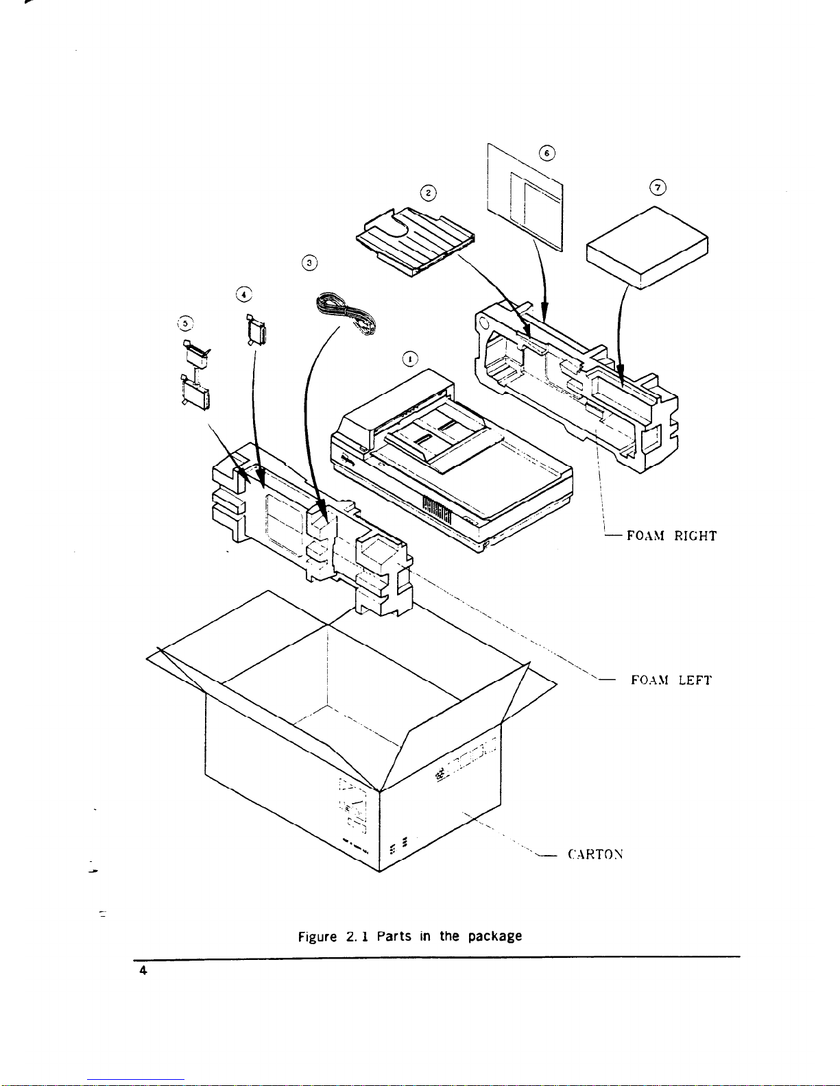
Check the items by referring to Figure 2.1 and the Checklist in the
table below.
For any missing items, please contact your nearest dealer or
distributor.
3
Page 5
‘- FOAM LEFl
Figure 2. 1 Parts in the package
4
Page 6
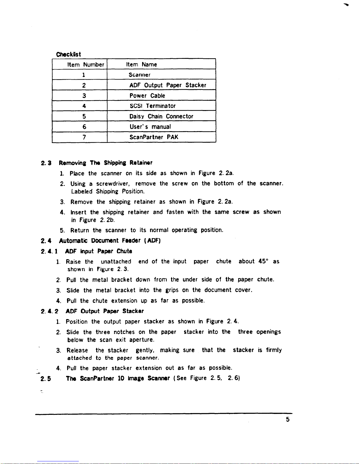
Checklist
Item Number
1
Item Name
Scanner
1
2
ADF Output Paper Stacker
3
Power Cable
4 SCSI Terminator
I 5 I
Daisy Chain Connector
I
6
User’ s manual
7
ScanPartner PAK
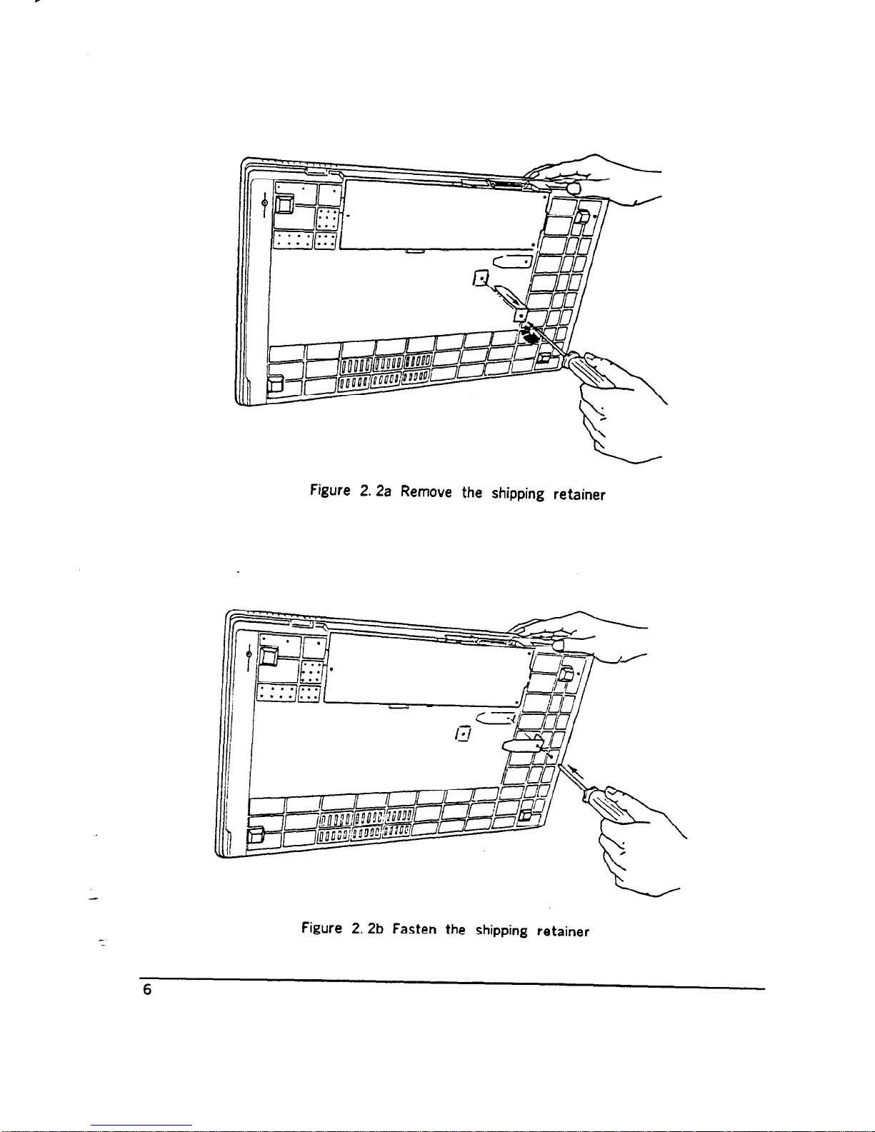
2.3 Removing The Shipping Retainer
1.
2.
3.
4.
5.
Place the scanner on its side as shown in Figure 2.2a.
Using a screwdriver, remove the screw on the bottom of the scanner.
Labeled Shipping Position.
Remove the shipping retainer as shown in Figure 2. 2a.
Insert the shipping retainer and fasten with the same screw as shown
in Figure 2. 2b.
Return the scanner to its normal operating position.
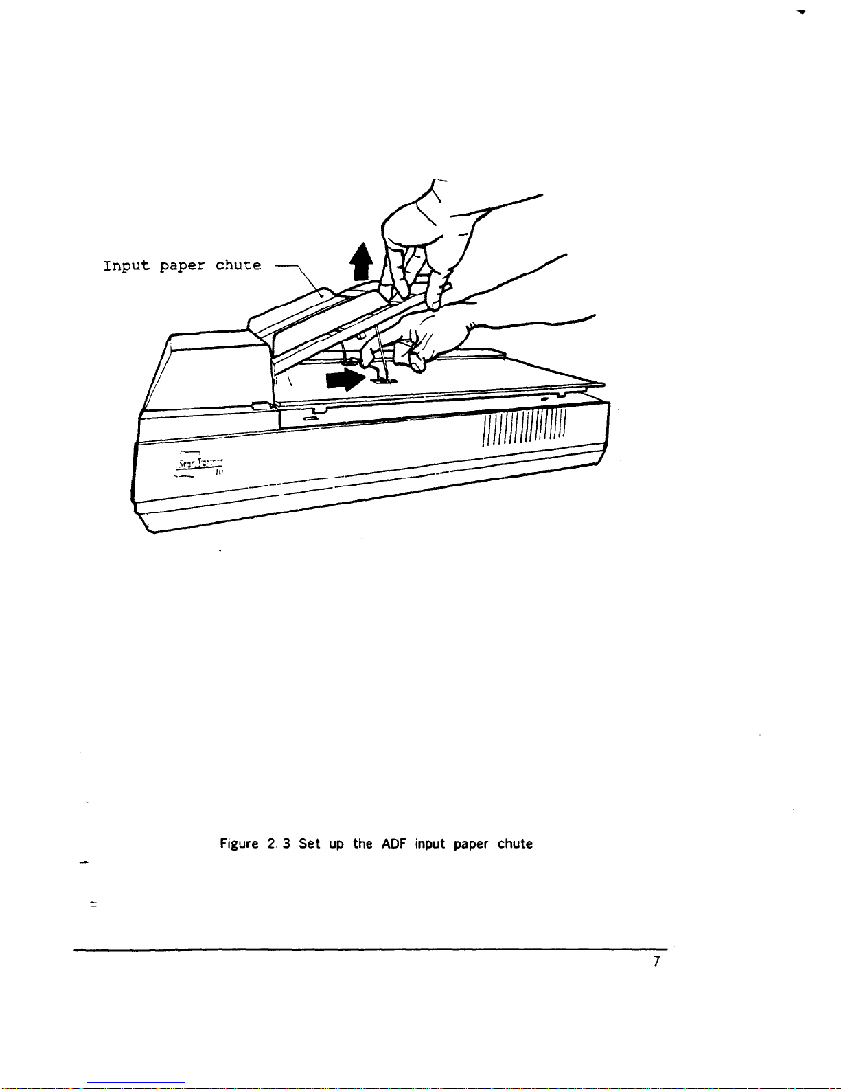
2.4 Automatic Dtiument Feeder (ADF)
ADF Input Paper Chute
Raise the unattached end of the input paper chute about 45” as
2.4.1
1.
2.
3.
4.
2.4.2
1.
2.
3.
4.
-2.5
:
shown in Figure 2. 3.
Pull the metal bracket down from the
Slide the metal bracket into the grips
Pull the chute extension up as far as
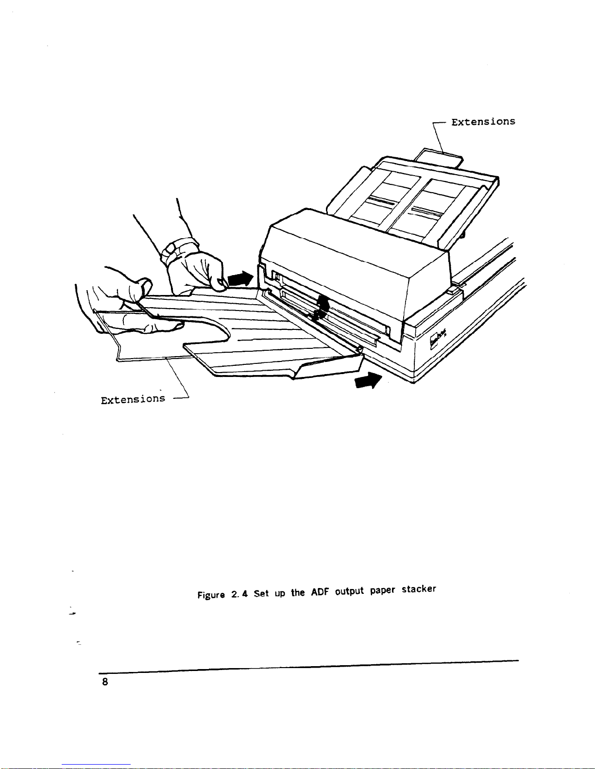
ADF Output Paper Stacker
under side of the paper chute.
on the document cover.
possible.
Position the output paper stacker as shown in Figure 2.4.
Slide the three notches on the paper
stacker into the three openings
below the scan exit aperture.
Release the stacker gently, making sure that the stacker is firmly
attached to the paper scanner.
Pull the paper stacker extension out as far as possible.
The ScanPartner 10 lmago Scanrmr (See Figure 2.5, 2.6)
5
Page 7
-
Figure 2. 2a Remove the shipping retainer
Figure 2. 2b Fasten the shipping retainer
6
Page 8
,--
Figure 2. 3 Set up the ADF input paper chute
7
Page 9
r
Extensions
Extensions 2
Figure 2.4 Set up the ADF output paper stacker
8
Page 10
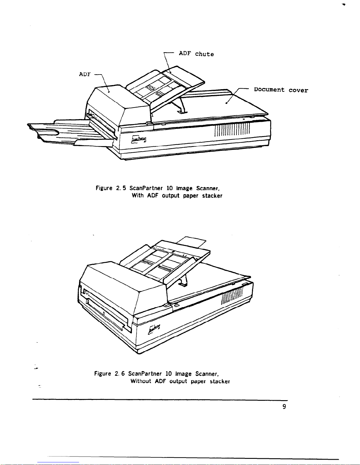
r
ADF chute
Figure 2.5 ScanPartner 10 Image Scanner,
With ADF output paper stacker
lent
Figure 2. 6 ScanPartner 10 Image Scanner,
Without ADF output paper stacker
9
cover
Page 11

2.6 Cable Connection
Two cables are required to operate the scanner: the SCSI signal cable and
thepower cable. The power cable connects the scanner to the power source.
TheSCSl signal cable connects the scanner to the host for image transfer.
2.6.1
1.
2.
3.
4.
2.6.2
Power Cabb Connection
Remove the power cable from the PVC bag.
Turn the power switch to the “off” position (“0” depressed).
Connect the female plug of the power cable to the scanner connector,
pressing firmly into place. ( See Figure 2. 7)
Connect the other end of the power cable to the power outlet,
pressing firmly into place.
SCSI Signal Connection
The devices linked to the SCSI interface are daisy- chained with each
other. A terminator is attached to the ends of the interface cable. User
can buy the SCSI cable in the computer stores. The specifications of
the SCSI cable is as below:
Name: SCSI Cable
Cable Specification:
50 pins to 50 pins, shielded.
Cable Length:
less than or equal to 6 meters.
SCSI Cable Connection
There. are two configurations for the connections.
Configuration I :
The number of devices attached to the SCSI bus
( including the host PC) is three or above. And the scanner is located in
the middle of the connection, as shown below.
SCSI device A
terminator
terminator
1.
2.
3.
Plug the MALE side of the “daisy- chain connectlor” to scanner’s
SCSI signal connector.
Plug one end of the SCSI cable into the SCSI connector of the device
A, and the other end of the cable to one female connector of the
Daisy- Chain connector of the scanner. As shown in Figure 2.8.
Plug one end of the SCSI cable into the SCSI connector of device B,
and the other end of the cable to the other female connector of the
Daisy- Chain connector.
10
Page 12

Configuration II: The number of devices attached to the SCSI
bus (including the host PC) is two. Or the number is three or
above,
and the scanner is located at the end of the connection,
as shown below.
Host PC
Scanner
I
Terminator
I
terminator
1.
2.
3.
SCSI
1.
2.
3.
4.
If there is already an other device linked to the host
via SCSI cable, remove the terminator form that device.
If the terminator is internal to that device, it is
recommended that the connection of Configuration I be used.
Plug the MALE side of the terminator to scanner’s SCSI
signal connector.
Plug one end of the SCSI cable into the FEMALE side of
the terminator,
and the other end of the cable to one
female connector of the previous device or the host.
spacif ications requires that:
Only one terminator may be attached to each end of the
daisy chain.
The total length of the daisy chain must not exceed 6
meters.
The vendor suggests that the SCSI cable be two
or three
meters in length to allow other device to be
attached to the SCSI bus.
Each device on the chain will be assigned a different ID.
Devices with the same SCSI ID will cause them to
malfunction. Please refer to Section 3.1.1 for selecting
the scanner’s SCSI ID.
There is no restriction on the position of the devices on
the daisy chain. Please see the configurations above.
11
Page 13

Power Cable
Figure 2. 7 Power cable connection
12
Page 14

Figure 2. 8 Signal cable connection
13
Page 15

CHAPTER 3 OPERATION
3.1 Power On
1. Depress the side of the power switch marked “1”.
2. Wait until the Power LED and the READY LED lights are on. If either
LED fails to light or if the Paper Jam LED lights, refer to Chapter 5
for troubleshooting, as shown in Figure 3. 1.
3.1.1 Sabct SCSI ID by turning the rotary switch in the back to a desirable
SCSI ID. The scanner ships with a default setting of “6”.
3.2 Scan Moda Options
The ScanParter 10 image scanner can scan documents in two modes:
The Flat- Bed mode or the automatic document feeder mode.
In Flat- Bed mode, the document cover is
lifted and ‘each page is scanned
one at a time and removed manually. Flat- Bed mode is particularly useful
when documents need to be scanned many times without being repositioned,
are particularly delicate or small or are bound. In ADF mode, a stack of
papers is scanned sequentially, without operator intervention. The ADF mode
is particularly useful when multiple sheets are being scanned.
The following two subsections describe the operation of each scanning mode.
3.2.1
1.
2.
3.
4.
5.
6.
3.2.2
1.
2.
3.
4.
5.
Ftat- Bed
Open the document cover.
Place the document face down on the documenit board with the top
edge towards the scan aperture, as shown in Figure 3.2.
Position the document so that its left side and top1 edge are in line with
the ruler guides next to the scanner glass, as shown in Figure 3. 3.
Close the document cover carefully,
being sure paper is flat against the
glass.
Start scan.
Note: Do not open the document cover during scanning.
When scanning completes, open the document cover carefully and
remove the document.
Automatic Paper Feeding
Place the document face down in the input paper chute. (Refer to Figure
3.4 in the next page. )
Slide the stack forward slightly so that it rests against the ADF sensor.
Move the both sides of the paper guide so that they touch both sides
of paper.
The first sheet will be automatically fed to the scanning position.
Start scan.
14
Page 16

Power switch
Figure 3.1 Power on
15
Page 17

Figure 3. 2 Flat- bed scanning ( I )
16
Page 18

Flgure 3. 3 Flat- bed scanning ( II )
17
Page 19

Figure 3.4 ADF scanning
18
Page 20

CHAPTER 4 REPLACEMENT OF LAMP UNIT
4.1 Removal of Lamp
1.
2.
3.
4.
5.
6.
7.
a.
9.
10.
11.
12.
13.
Turn the scanner off.
R,aise the document cover.
Turn the scanner on.
Watch the lamp. When it is positioned at the dot between the “1” and
” 2” ,
turn the scanner off again.
Use screwdriver to remove the screw on the bottom right of the
document cover. shown in Figure 4.1.
Pull the spare lamp holder to the right and then towards you.
Remove the new lamp.
Close the document cover.
Remove the screw
on the rear side of the scanner as shown in
Figure 4. 2.
Lift the rear side of the document cover, and remove the plastic
plate located above the signal connector as shown in Figure 4. 3.
Turn the copper bar
counterclockwise to remove it from the scanner
as shown in Figure 4. 4.
Remove the metal plate as shown in Figure 4. 5 and 4.6.
Remove the lamp from the scanner by pulling it straight out. If
the lamp‘ is difficult to remove, use pliers to remove it, as shown
in Figure 4. 7.
4.2 Installing the New Lamp
1. Insert the new lamp into the lamp holder inside the scanner.
(The lamp can be seen through
the document glass. ) Position the
lamp so that the two pins are vertical.
2. Use the small window on the top cover towards the front to check the
pin position as you slide the lamp into place.
3. Press the lamp into place so that the two pins are inserted
firmly into the black bracket, as shown in Figure 4. 8.
4. Insert the metal plate over the pins at the other end of the lamp.
5. Screw the copper bar into place.
6. Lift the rear side of the document cover again.
7. Place the plastic plate vertically over the lamp unit.
8. Turn the screw to fasten the plastic plate.
9. Replace the document cover.
19
Page 21

Figure 4. 1 Replacement of the lamp unit:
Take out the spare lamp
20
Page 22

Figure 4.2 Replacement of the lamp unit:
Remove the screw
21
Page 23

Figure 4. 3 Replacement of the lamp unit:
Remove the lamp holder cover
22
Page 24

Figure 4.4 Replacement of the lamp unit:
scroll Out the copper bar
23
Page 25

Figure 4.5 Replacement of the lamp unit:
Removal of metal plate ( I)
24
Page 26

Figure 4.6 Replacement of the lamp unit:
Removal of metal plate ( II)
25
Page 27

Figure 4. 7 Replacement of the bmp unit:
Pull out that bmp
26
Page 28

Figure 4. 8 Replacement of the lamp unit:
insertion of lamp
27
Page 29

CHAPTER 5 PAPER JAMS
Should a paper jam occur in the ADF, use the following procedures.
1. Turn the scanner off.
2. Push the botton near the front left side of the scanner as shown
in Figure 5. 1.
3. The ADF unit module will lift a little.
4. Lift the right side of the ADF module as far as possible.
5. Remove the jammed paper slowly as show in Figure 5.2.
28
Page 30

Figure 5. 1 Paper Jammed: push the botton
29
Page 31

Figure 5.2 Paper Jammed: pull out the paper
30
Page 32

CHAPTER 6:
DIAGNOSWS
The ScanPartner 10 runs a diagnostic operation when it is turned on. If the
result is ok, the scanner will initialize itself and then enter the “READY” state.
There are three LEDs that can be seen on the panel. Each LED is assigned a
name: READY, POWER, and JAM.
The “READY” state is indicated by the “READY” and
“POWER” LEDs being on and
the “JAM” LED being off.
If the diagnostic fails, the scanner will show the error message on LED
displays as shown below.
Blinking
OFF
Lamp Fail
1.
Paper Jam
Please refer to Chapter 5 for removing the paper jam condition.
After removing all the papers from the ADF, and JAM LED is still
on after re- powering, please contact your nearest dealer or
dirtributer.
2.
3.
ADF Cover Open
Please refer to Chapter 5 for opening the ADF cover and closing it.
Power off and then power on the scanner again. If this condition
still exists,
please contact your nearest dealer or distributer.
Lamp Fail
This error means that the lamp
being used may be burned out or
the light is too dark due to aging. Please refer to Chapter 4 for
replacing the new lamp. If necessary, please contact your nearest
dealer for a new lamp. If the error still exists after the old lamp is
replaced with a new one, please contact your nearest dealer or
distributer.
4.
POWER LED is off after the scanner is turned on
1. Check if the power cable is firmly plugged into the outlet and the
power connector of the scanner.
2. If the power is
connected and POWER LED remains off, please
contact your nearest dealer or distributer.
5.
Note that if the “READY” and “JAM” LEDs blink simultaneously and
constantly, please
contact your nearest dealer or distributer. Such
errors require a qualified technician for repair.
31
 Loading...