

Fujitsu SCALEOVIEW S17-2, SCALEOVIEW S19-2, Encore 300, Encore 500, Encore 550 Operating Manual
...Page 1
Encore® and Eclipse® Series
Owner’s Manual
MDE-3893P
Page 2
Computer Programs and Documentation
All Gilbarco Inc. and/or Veeder Root Company computer programs (including software on diskettes and within memory chips) and documentation are copyrighted by, and shall
remain the property of, Gilbarco Inc. and/or Ve eder Root Company. Such computer programs and documents may also contain trade secret information. The duplication, disclosure,
modification, or unauthorized use of computer programs or documentation is strictly prohibited, unless otherwise licensed by Gilbarco Inc. and/or Veeder Root Company.
Federal Communications Commission (FCC) Warning
This equipment has been tested and found to comply with the limits for a Class A digital device pursuant to Part 15 of the FCC Rules. These limits are designed to provide
reasonable protection against harmful interference when the equipment is operated in a commercial environment. This equipment generates, uses, and can radiate radio frequency
energy, and if not installed and used in accordance with the instruction manual, may cause harmful interference to radio communications. Operation of this equipment in a
residential area is likely to cause harmful interference in whic h case the user will be required to correct the interference at his own expense. Changes or modifications not expressly
approved by the manufacturer could void the user’s authority to operate this equipment.
Approvals
Gilbarco is an ISO 9001:2008 registe red company.
Underwriters Laboratories (UL):
U L File# Products listed with U L
MH1941
MH8467 Transac System 1000 and PAM 1000
E105106 Dell DH M M i n i t o w e r
E165027 G-SITE a n d P a s s p o r t S y s t e m s
All Gilbarco pumps and dispensers that bear
the UL listing mark.
National Conference of Weights and Measures (NCWM) - Certificate of Conformance (CoC):
Gilbarco pumps and dispensers are evaluated by NCWM under the National Type Evaluation Program (NTEP). NCWM has issued the following CoC:
CoC# Product Model # CoC# Product Model #
02-019 Encore Nxx 02-036 Legacy Jxxx
02-020 Eclipse Exx
02-025
02-029 CRIND — G-SITE Mini Tower PA0301
02-030
Meter - C Series PA024NC10 G-SITE Distribution Box PA0306
Meter - C Series PA024TC10 G-SITE Keyboard PA0304
TS-1000 Console — G-SITE Monitor PA0303
TS-1000 Controller PA0241 G-SITE Printer (Citizen) PA0308
Distribution Box PA0242 02-038 C+ Meter T19976
Meter - EC Series PA024EC10 02-039 Passport PA0324
VaporVac Kits CV 02-040 Ecometer T20453
California Air Resources Board (CARB):
Executive Order # Product
G-70-52-AM Balance Vapor Recovery
G-70-150-AE VaporVac
G-SITE Printer (Epson) PA0307
02-037
05-001 Titan KXXY Series
Trademarks
Non-registered trademarks
Applause™ Media System G-SITE® Lite™SMART Meter
™
CIM
™
C-PAM
™
ECR
™
EMC
™
FlexPay
™
G-CAT
™
Gilbert
G-SITE® Link
™
™
Highline
Horizon
MultiLine
Optimum™ Series TCR
PAM™ 1000 Titan
™
PAM
SMART Connect™ValueLine
SMART CRIND
™
™
™
SmartPad
Surge Management System
Tank Monitor
™
™
Ultra-Hi
™
™
™
™
™
Registered trademarks
CRIND
Dimension® Series Legacy
™
e-CRIND
®
Eclipse
®
Encore
G-SITE
Gilbarco
®
®
®
®
®
InfoScreen
®
Making Things Better®Trimline
®
MPD
®
Passport
®
Performer
Transac
Transac® System 1000
TRIND
Vap or Vac
The Advantage® Series
®
®
®
®
Additional US and foreign trademarks pending.
Other brand or product names shown may be
trademarks or registered trademarks of their
respective holders.
This document is subject to change without notice.
E-mail: literature@gilbarco.com · Internet: http://www.gilbarco.com
© 2011 Gilbarco Inc. All Rights Reserved
Page 3

Table of Contents
Table of Contents
1 – Introduction 1
Purpose. . . . . . . . . . . . . . . . . . . . . . . . . . . . . . . . . . . . . . . . . . . . . . . . . . . . . . . . . . . . . . . . . . . . . . . . . .1
Intended Users . . . . . . . . . . . . . . . . . . . . . . . . . . . . . . . . . . . . . . . . . . . . . . . . . . . . . . . . . . . . . . . . . . . .1
Scope . . . . . . . . . . . . . . . . . . . . . . . . . . . . . . . . . . . . . . . . . . . . . . . . . . . . . . . . . . . . . . . . . . . . . . . . . . .1
Related Documents. . . . . . . . . . . . . . . . . . . . . . . . . . . . . . . . . . . . . . . . . . . . . . . . . . . . . . . . . . . . . . . . .1
Abbreviations and Acronyms. . . . . . . . . . . . . . . . . . . . . . . . . . . . . . . . . . . . . . . . . . . . . . . . . . . . . . . . . .2
2 – Important Safety Information 3
3 – Introducing the Encore/Eclipse Series 7
Encore 300 and Encore 500 . . . . . . . . . . . . . . . . . . . . . . . . . . . . . . . . . . . . . . . . . . . . . . . . . . . . . . . . . .7
Encore 550 . . . . . . . . . . . . . . . . . . . . . . . . . . . . . . . . . . . . . . . . . . . . . . . . . . . . . . . . . . . . . . . . . . . . . . .8
Encore S Series. . . . . . . . . . . . . . . . . . . . . . . . . . . . . . . . . . . . . . . . . . . . . . . . . . . . . . . . . . . . . . . . . . . .9
Americans with Disabilities Act (ADA) Requirements . . . . . . . . . . . . . . .10
DEF Dispenser . . . . . . . . . . . . . . . . . . . . . . . . . . . . . . . . . . . . . . . . . . . . . . . . . . . . . . . . . . . . . . . . . . .11
Eclipse Series . . . . . . . . . . . . . . . . . . . . . . . . . . . . . . . . . . . . . . . . . . . . . . . . . . . . . . . . . . . . . . . . . . . .12
Understanding Date Codes and Serial Numbers . . . . . . . . . . . . . . . . . . . . . . . . . . . . . . . . . . . . . . . . .13
Understanding Date Codes . . . . . . . . . . . . . . . . . . . . . . . . . . . . . . . . . . .13
Understanding Model Codes . . . . . . . . . . . . . . . . . . . . . . . . . . . . . . . . . .13
Common Functions . . . . . . . . . . . . . . . . . . . . . . . . . . . . . . . . . . . . . . . . . . . . . . . . . . . . . . . . . . . . . . . .15
Displaying the Last Transaction. . . . . . . . . . . . . . . . . . . . . . . . . . . . . . . .15
Displaying Pump Totals for Encore/Eclipse Units . . . . . . . . . . . . . . . . . .16
Grade Number Reference Chart . . . . . . . . . . . . . . . . . . . . . . . . . . . . . . .17
Operating the Units . . . . . . . . . . . . . . . . . . . . . . . . . . . . . . . . . . . . . . . . . . . . . . . . . . . . . . . . . . . . . . . .19
Console Mode (Two-wire) . . . . . . . . . . . . . . . . . . . . . . . . . . . . . . . . . . . .19
Standalone Mode. . . . . . . . . . . . . . . . . . . . . . . . . . . . . . . . . . . . . . . . . . .19
4 – Preparing to Service Units 21
Important Considerations for DEF Dispensers . . . . . . . . . . . . . . . . . . . . . . . . . . . . . . . . . . . . . . . . . . .21
Important Considerations for Units with Ecometers . . . . . . . . . . . . . . . . . . . . . . . . . . . . . . . . . . . . . . .22
Important Considerations When Changing Fuel Types. . . . . . . . . . . . . . . . . . . . . . . . . . . . . . . . . . . . .23
Dispensing Gasoline/Ethanol Blends . . . . . . . . . . . . . . . . . . . . . . . . . . . . . . . . . . . . . . . . . . . . . . . . . .24
Important Requirements for E85 Units . . . . . . . . . . . . . . . . . . . . . . . . . . . . . . . . . . . . . . . . . . . . . . . . .24
Call Gilbarco First . . . . . . . . . . . . . . . . . . . . . . . . . . . . . . . . . . . . . . . . . . . . . . . . . . . . . . . . . . . . . . . . .25
Service Preparation. . . . . . . . . . . . . . . . . . . . . . . . . . . . . . . . . . . . . . . . . . . . . . . . . . . . . . . . . . . . . . . .25
Before Making a Service Call. . . . . . . . . . . . . . . . . . . . . . . . . . . . . . . . . .25
Description of the Problem. . . . . . . . . . . . . . . . . . . . . . . . . . . . . . . . . . . .25
Warranty Service . . . . . . . . . . . . . . . . . . . . . . . . . . . . . . . . . . . . . . . . . . .25
Station Security . . . . . . . . . . . . . . . . . . . . . . . . . . . . . . . . . . . . . . . . . . . . . . . . . . . . . . . . . . . . . . . . . . .25
Enhancing Security . . . . . . . . . . . . . . . . . . . . . . . . . . . . . . . . . . . . . . . . .26
Additional Security in Encore S Series Units. . . . . . . . . . . . . . . . . . . . . . . . . . . . . . . . . . . . . . . . . . . . .27
Important Installation Information. . . . . . . . . . . . . . . . . . . . . . . . . . . . . . .28
Unit Commissioning . . . . . . . . . . . . . . . . . . . . . . . . . . . . . . . . . . . . . . . . .29
Error Codes . . . . . . . . . . . . . . . . . . . . . . . . . . . . . . . . . . . . . . . . . . . . . . .29
Replacement Parts. . . . . . . . . . . . . . . . . . . . . . . . . . . . . . . . . . . . . . . . . .29
Specialized Training. . . . . . . . . . . . . . . . . . . . . . . . . . . . . . . . . . . . . . . . .30
MDE-3893P Encore® and Eclipse® Series Owner’s Manual · December 2011 Page i
Page 4

Table of Contents
5 – Maintaining Units 31
General Safety Considerations. . . . . . . . . . . . . . . . . . . . . . . . . . . . . . . . . . . . . . . . . . . . . . . . . . . . . . . 31
Periodic Inspections . . . . . . . . . . . . . . . . . . . . . . . . . . . . . . . . . . . . . . . . . . . . . . . . . . . . . . . . . . . . . . . 32
Performing General and Component Maintenance Inspections . . . . . . . 32
Periodic Maintenance Requirements . . . . . . . . . . . . . . . . . . . . . . . . . . . . . . . . . . . . . . . . . . . . . . . . . . 43
Changing CRIND Device Printer Paper . . . . . . . . . . . . . . . . . . . . . . . . . 43
Cleaning the Printer . . . . . . . . . . . . . . . . . . . . . . . . . . . . . . . . . . . . . . . . 44
Printer Paper Ordering Information. . . . . . . . . . . . . . . . . . . . . . . . . . . . . 44
Changing the Receipt Paper in the M00317A00X Printer. . . . . . . . . . . . 45
Changing the Receipt Paper in USB Printer (M04119A001) . . . . . . . . . 48
Changing the Receipt Paper in USB Sliding Printer (M06972A001). . . . 51
Changing the Receipt Paper in USB Sliding Printer for
Encore S Series Enhanced Bezel (M07885A001) . . . . . . . . . . . . . . . . . 55
Cleaning the CRIND Device in the M00317A00X Printer . . . . . . . . . . . . 59
Clearing Paper Jams in USB Printer (M04119A001) . . . . . . . . . . . . . . . 59
Clearing Paper Jams in USB Sliding Printer (M06972A001) . . . . . . . . . 61
Special Maintenance Instructions. . . . . . . . . . . . . . . . . . . . . . . . . . . . . . . . . . . . . . . . . . . . . . . . . . . . . 62
Cleaning and Detailing the Unit. . . . . . . . . . . . . . . . . . . . . . . . . . . . . . . . 62
Glossary Glossary-1
Index Index-1
Page ii MDE-3893P Encore® and Eclipse® Series Owner’s Manual · December 2011
Page 5

Purpose Introduction
1 – Introduction
Purpose
This manual provides instructions for safely operating, programming, and maintaining
Encore
referred to as units, unless otherwise specifically stated).
Intended Users
This manual is written for the owners and operators of Encore and Eclipse units.
®
300, Encore 500/550, Encore S Series, and Eclipse® pumps/dispensers (hereafter
Scope
This manual provides the following information about the Encore and Eclipse units:
• Operating the units
• Programming Encore and Eclipse units
• Preparing the units for service
• Maintaining the units
Related Documents
Document
Number
MDE-3802 Encore & Eclipse Site Prep Manual • Encore and Eclipse
MDE-3985 Encore Installation Manual • Encore and Eclipse
MDE-3986 Eclipse Installation Manual • Encore and Eclipse
MDE-4732 Encore and Eclipse Series Owner’s Programming Manual • Encore and Eclipse
PT-1798 Consumable Parts List Parts Manual
PT-1936 Encore Illustrated Parts Manual • Parts Manual
TRP-1856 Major Software Release Gilbarco® Extranet
Title GOLD Library
• Encore and Eclipse Installers
• Site Prep
• Encore and Eclipse Installers
• Encore and Eclipse Installers
• Footprint & Elevation Library
• Encore and Eclipse Installers
• Encore and Eclipse Installers
• Encore and Eclipse
MDE-3893P Encore® and Eclipse® Series Owner’s Manual · December 2011 Page 1
Page 6

Introduction Abbreviations and Acronyms
Abbreviations and Acronyms
Term Description
ASC Authorized Service Contractor
CFR Code of Federal Regulations
™
CIM
CRIND® Card Reader IN Dispenser
CSC Customer Specified Contractor
DEF Diesel Exhaust Fluid
DLT Displaying Last Transaction
FCC Federal Communications Commission
FF Flexible Fuels
IFSF International Forecourt Standards Forum
LCD Liquid Crystal Display
LON Local Operating Network
MOC Major Oil Company
MPD
NEC National Electrical Code
NFPA National Fire Protection Association
OSHA Occupational Safety and Hazard
PIN Personal Identification Number
PPP Programmable Pump Preset
PPU Price Per Unit (Price Per Volume)
STP Submersible Turbine Pump
TRIND®Transmitter/Receiver IN Dispenser
UL
USB Universal Serial Bus
VR Vapor Recovery
Customer Interface Module
®
Multi Product Dispenser
Administration
®
Underwriters Laboratory
Page 2 MDE-3893 P Encore® and Eclipse® Series Owner’s Manual · December 2011
Page 7
2 – Important Safety Information
Important Safety Information
Notes: 1) Save this Important Safety Information section
in a readily accessible location.
2) Although DEF is non-flammable, Diesel is
flammable. Therefore, for DEF cabinets that are
attached to Diesel dispensers, follow all the
notes in this section that pertain to flammable
fuels.
This section introduces the hazards and safety precautions
associated with installing, inspecting, maintaining or servicing
this product. Before performing any task on this product, read
this safety information and the applicable sections in this
manual, where additional hazards and safety precautions for
your task will be found. Fire, explosion, electrical shock or
pressure release could occur and cause death or serious injury,
if these safe service procedures are not followed.
Preliminary Precautions
You are working in a potentially dangerous environment of
flammable fuels, vapors, and high voltage or pressures. Only
trained or authorized individuals knowledgeable in the related
procedures should install, inspect, maintain or service this
equipment.
Emergency Total Electrical Shut-Off
The first and most important information you must know is how
to stop all fuel flow to the pump/dispenser and island. Locate
the switch or circuit breakers that shut off all power to all fueling
equipment, dispensing devices, and Submerged Turbine
Pumps (STPs).
Read the Manual
Read, understand and follow this man ual and any other labels
or related materials supplied with this equipment. If you do not
understand a procedure, call a Gilbarco Authorized Service
Contractor or call the Gilbarco Support Center at
1-800-800-7498. It is imperative to your safety and the safe ty of
others to understand the procedures before beginning work.
Follow the Regulations
Applicable information is available in National Fire Protection
Association (NFPA) 30A; Code for Motor Fuel Dispensing
Facilities and Repair Garages, NFPA 70; National Electrical
Code (NEC), Occupational Safety and Hazard Association
(OSHA) regulations and federal, state, and local codes. All
these regulations must be followed. Failure to install, inspect,
maintain or service this equipment in accordance with these
codes, regulations and standards may lead to legal citations
with penalties or affect the safe use and operation of the
equipment.
Replacement Parts
Use only genuine Gilbarco replacement parts and retrofit kits
on your pump/dispenser. Using parts other than genuine
Gilbarco replacement parts could create a safety hazard and
violate local regulations.
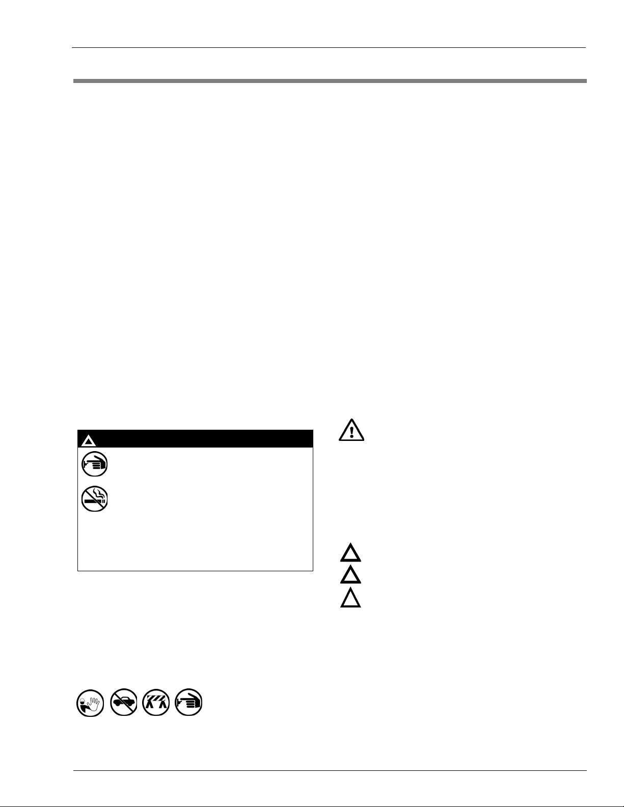
Safety Symbols and Warning Words
This section provides important information about warning
symbols and boxes.
Alert Symbol
!
WARNING
!
The EMERGENCY STOP, ALL STOP, and
PUMP STOP buttons at the cashier ’s station
WILL NOT shut off electrical power to the
pump/dispenser. This means that even if you
activate these stops, fuel may continue to flow
Total Electrical Shut-Off Before Access
Any procedure that requires access to electrical component s or
the electronics of the dispenser requires total electrical shut off
of that unit. Understand the function and location of this switch
or circuit breaker before inspecting, installing, maintaining, or
servicing Gilbarco equipment.
Evacuating, Barricading and Shutting Off
Any procedure that requires access to the pump/dispenser or
STPs requires the following actions:
• An evacuation of all unauthorized persons and vehicles from
the work area
• Use of safety tape, cones or barricades at the affected unit(s)
• A total electrical shut-off of the affected unit(s)
uncontrolled.
You must use the TOTAL ELECTRICAL
SHUT-OFF in th e cas e of an emerge nc y a nd no t
the console’s ALL STOP and PUMP STOP or
similar keys.
This safety alert symbol is used in this manual and on
warning labels to alert you to a precaution which must be
followed to prevent potential personal safety hazards. Obey
safety directives that follow this symbol to avoid possib le inj ury
or death.
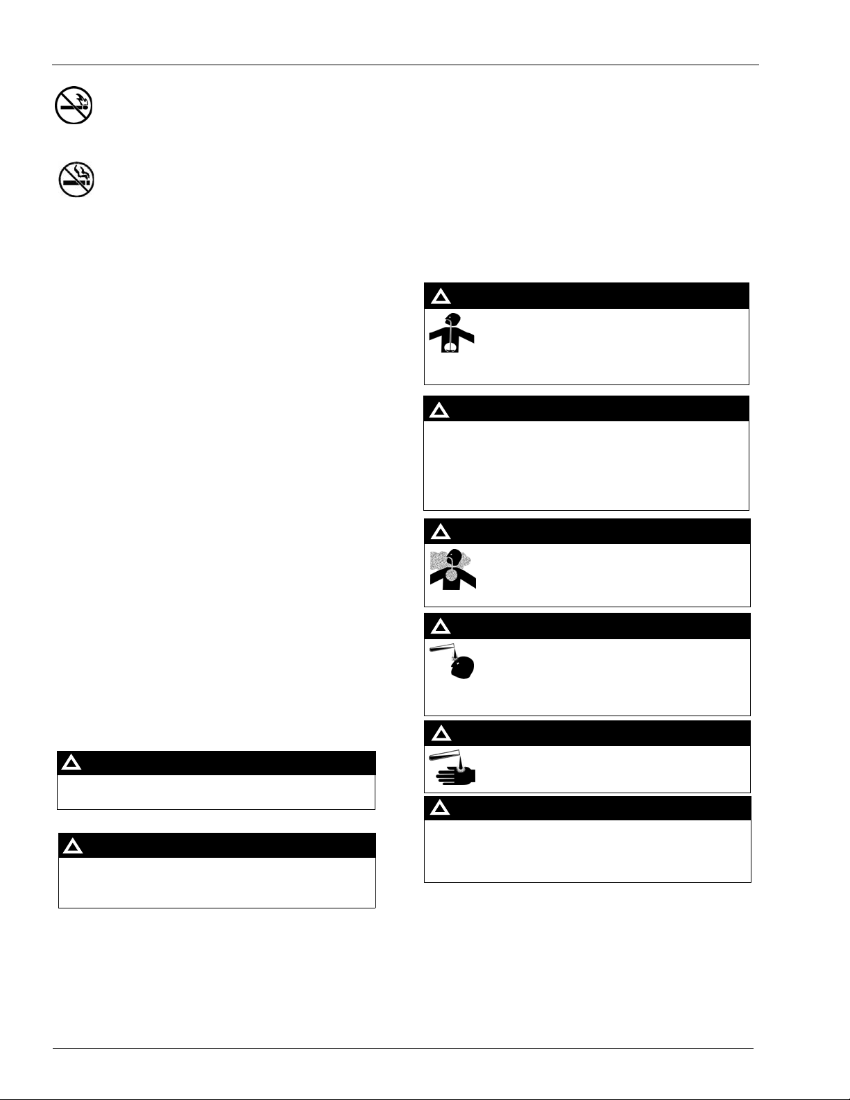
Signal Words
These signal words used in this manual and on warning labels
tell you the seriousness of particular safety hazards. The
precautions below must be followed to prevent death, injury or
damage to the equipment:
DANGER: Alerts you to a hazard or unsafe practice
!
!
which will result in death or serious injury.
WARNING: Alerts you to a hazard or unsafe practice
!
!
that could result in death or serious injury.
CAUTION with Alert symbol: Designates a hazard or
!
unsafe practice which may result in minor injury.
CAUTION without Alert symbol: Designates a hazard o r
unsafe practice which may result in property or
equipment damage.
Working With Fuels and Electrical Energy
Prevent Explosions and Fires
Fuels and their vapors will explode or burn, if ignited. Spilled or
leaking fuels cause vapors. Even filling customer tanks will
cause potentially dangerous vapors in the vicinity of the
dispenser or island.
DEF is non-flammable. Therefore, explosion and fire safety
warnings do not apply to DEF fluid lines.
MDE-3893P Encore® and Eclipse® Series Owner’s Manual · December 2011 Page 3
Page 8
Important Safety Information
No Open Fire
In an Emergency
Inform Emergency Personnel
Compile the following information and inform emergency
Open flames from matches, lighters, welding torches or
other sources can ignite fuels and their vapors.
No Sparks - No Smoking
personnel:
• Location of accident (for example, address, front/back of
building, and so on)
• Nature of accident (for example, possible heart attack, run
over by car, burns, and so on )
Sparks from starting vehicles, starting or using power tools,
burning cigarettes, cigars or pipes can also ignite fuels and their
vapors. Static electricity, including an electrostatic charge on
your body, can cause a spark sufficient to ignite fuel vapors.
Every time you get out of a vehicle, touch the metal of your
• Age of victim (for example, baby, teenager, middle-age,
elderly)
• Whether or not victim has received first aid (for example,
stopped bleeding by pressure, and so on)
• Whether or not a victim has vomited (for example, if
swallowed or inhaled something, and so on)
vehicle, to discharge any electrostatic charge before you
WARNING
approach the dispenser island.
!
Gasoline/DEF ingested may cause
Working Alone
It is highly recommended that someone who is capable of
rendering first aid be present during servicing. Familiarize
yourself with Cardiopulmonary Resuscitation (CPR) methods, if
unconsciousness and burns to internal organs.
Do not induce vomiting. Keep airway open.
Oxygen may be needed at scene. Seek medical
advice immediately.
you work with or around high voltages. This information is
available from the American Red Cross . Alw ay s ad vise the
station personnel about where you will be working, and caution
them not to activate power while you are working on the
equipment. Use the OSHA Lockout/Tagout procedures. If you
are not familiar with this requirement, refer to this information in
the service manual and OSHA documentation.
Working With Electricity Safely
Ensure that you use safe and established practices in working
with electrical devices. Poorly wired devices may cause a fire,
explosion or electrical shock. Ensure that grounding
connections are properly made. Take care that sealing devices
and compounds are in place. Ensure that you do not pinch wires
when replacing covers. Follow OSHA Lockout/Tagout
WARNING
!
DEF generates ammonia gas at higher tempe r atures.
When opening enclosed panels, allow the unit to air out to
avoid breathing vapors.
If respiratory difficulties develop, move victim away from
source of exposure and into fresh air. If symptoms persist,
seek medical attention.
WARNING
!
Gasoline inhaled may cause unconsciousness
and burns to lips, mouth and lungs.
Keep airway open.
Seek medical advice immediately.
requirements. Station employees and service contractors need
WARNING
to understand and comply with th is program completely to
ensure safety while the equipment is down.
Hazardous Materials
Some materials present inside electronic enclosures may
present a health hazard if not handled correctly . Ensure that you
clean hands after handling equipment. Do not place any
equipment in the mouth.
!
WARNING
The pump/dispenser contains a chemica l known to the
State of California to cause cancer.
WARNING
!
The pump/dispenser contains a chemical known to the
State of California to cause birth defects or other
reproductive harm.
!
Gasoline/DEF spilled in eyes may cause burns to
eye tissue.
Irrigate eyes with water for approximately
15 minutes.
Seek medical advice immediately.
WARNING
!
Gasoline/DEF spilled on skin may cause burns.
Wash area thoroughly with clear water.
Seek medical advice immediately.
!
WARNING
DEF is mildly corrosive. Avoid contact with eyes, skin, and
clothing. Ensure that eyewash stations and safety
showers are close to the work location. Seek medical
advice/recommended treatment if DEF spills into eyes.
IMPORTANT: Oxy ge n may be ne ed e d at scene if gasoline has
been ingested or inhaled. Seek medical advice immediately.
Lockout/Tagout
Lockout/Tagout covers servicing and maintenance of machines
and equipment in which the unexpected energization or st art-up
of the machine(s) or equipment or release of stored energy
could cause injury to employees or personnel. Lockout/Tagout
applies to all mechanical, hydraulic, chemical, or other energy,
but does not cover electrical hazards. Subpart S of 29 CFR Part
1910 - Electrical Hazards, 29 CFR Part 1910.333 contains
specific Lockout/Tagout provision for electrical hazards.
Page 4 MDE-3893P Encore® and Eclipse® Series Ow ner’s Manual · December 2011
Page 9
Hazards and Actions
Important Safety Information
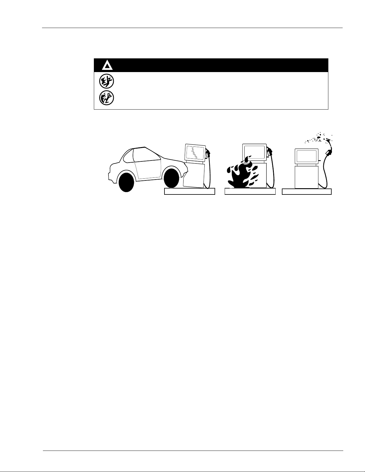
!
The following actions are recommended regarding these hazards:
• Do not go near a fuel spill or allow anyone else in the area.
• Use station EMERGENCY CUTOFF immediately. Turn off all system circuit breakers to the
island(s).
• Do not use console E-STOP, ALL STOP, and PUMP STOP to shut off power. These keys do not
remove AC power and do not always stop product flow.
• Take precautions to avoid igniting fuel. Do not allow starting of vehicles in the area. Do not allow
open flames, smoking or power tools in the area.
• Do not expose yourself to hazardous conditions such as fire, spilled fuel or exposed wiring.
• Call emergency numbers.
WARNING
Spilled fuels, accidents involving pumps/dispensers, or uncontrolled fuel flow create a
serious hazard.
Fire or explosion may result, causing serious injury or death.
Follow established emergency procedures.
DEF is non-flammable. However it can create a slip hazard. Clean up spills promptly.
Collision of a Vehicle with Unit Fire at Island Fuel Spill
MDE-3893P Encore® and Eclipse® Series Owner’s Manual · December 2011 Page 5
Page 10

Important Safety Information
This page is intentionally left blank.
Page 6 MDE-3893P Encore® and Eclipse® Series Ow ner’s Manual · December 2011
Page 11
Encore 300 and Encore 500 Introducing the Encore/Eclipse Series
P
RE
S
S
91
$
P
RI
CE
P
E
R
U
N
I
T
U
.
S
.
R
E
G
U
L
A
T
I
O
N
S
P
RE
S
S
89
$
P
R
I
C
E
P
E
R
U
N
I
T
U
.
S
.
R
E
G
UL
A
T
I
O
NS
P
RE
S
S
87
$
P
R
I
C
E
P
E
R
U
NI
T
U
.
S
.
R
E
G
UL
A
T
I
O
NS
3 – Introducing the Encore/Eclipse Series
This chapter provides illustrations of the Encore and Eclipse units and their components. Refer
to this chapter when you perform the procedures in this manual.
Encore 300 and Encore 500
The Encore 300 and 500 units, which are similar in appearance are shown below. However,
each series has its own hardware/software package. For information on programming the unit,
refer to “Programming Encore 300” in MDE-4732 Encore and Eclipse Series Owner’s
Programming Manual. All options may not be available on your unit.
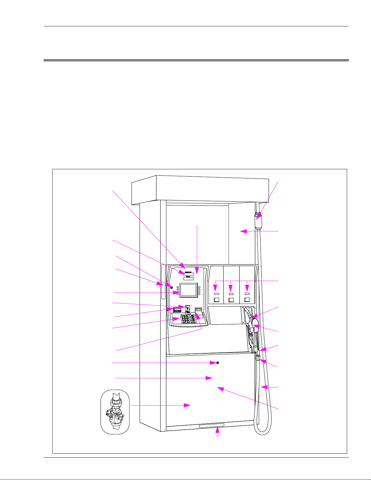
Figure 3-1: Encore 300 and Encore 500 Units
Breakaway
Serial Number Label (on
Units manufactured after
January 2003) is found
inside the CIM
Main Display
CIM Door Lock
Manager’s Keypad (not
shown) can be found
behind the CIM door.
Available but not
shown:
- Totalizer Option
- TRIND Option
- Scanner Option
Location of Label for
Approved Vapor Recovery
(VR) Nozzles and Federal
Communications Commission
(FCC) Label
Recommended Location
of Static Electricity
Warning Label
CRIND Display
Card Reader
Cash Acceptor
CRIND Keypad and
Optional PPP
CRIND Device Printer
Door Lock
Lower Panel
Shear Valves and Unions behind
Lower Panel (not shown)
PPU Display and Grade
Select Buttons
Boot Area
Nozzle
Pump Handle (Lift to Start
Handle Units)
Swivel
Hose
Brand Advertising Panel
Serial Number Label (on Units Manufactured before January 2003)
MDE-3893P Encore® and Eclipse® Series Owner’s Manual · December 2011 Page 7
Page 12
Introducing the Encore/Eclipse Series Encore 550
Encore 550
The Encore 550 unit has an enhanced appearance for the columns and canopy, when compared
to the Encore 300 and 500 units. The following illustration shows an Encore 550 unit with
SMAR T Meter
to “Programming Encore 500 and 550, Encore S Series and Eclipse” in MDE-4732 Encore and
Eclipse Series Owner’s Programming Manual. All options may not be available on your unit.
Figure 3-2: Encore 550 Unit
Serial Number Label is
found inside the CIM
Main Display
™
dispenser and its components. For information on programming the unit, refer
Breakaway for all Encore units
The VR hose, nozzle information
and FCC label are found on the
right side when facing Side 1 of
the dispenser.
is located near the hose casting
at the top of the
Pump/Dispenser for units
without Hose Retrievers. For
units with Hose Retrievers, the
breakaway is located near the
Nozzle.
Manager’s Keypad (not shown)
can be found behind the CIM
Door
CIM Door Lock
CRIND Display
Cash Acceptor
Card Reader
CRIND or PPP Keypad
CRIND Device Printer
Door Lock
Available but not shown:
- Totalizer Option
- TRIND Option
- Scanner Option
PPU Display and Grade
Select Buttons
Boot Area
Nozzle (not shown)
Brand Advertising Panel
Lower Panel
Shear Valve,
Unions, and Fuel
Filter behind Lower
Panel (not shown)
Page 8 MDE-3893 P Encore® and Eclipse® Series Owner’s Manual · December 2011
Page 13

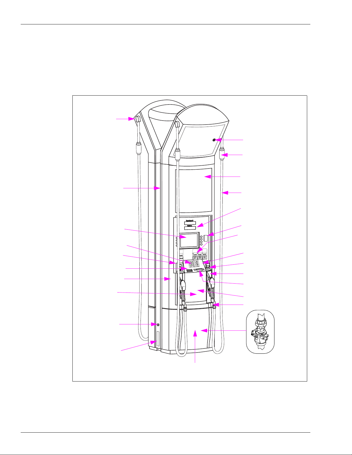
Encore S Series Introducing the Encore/Eclipse Series
Encore S Series
The Encore S series units offer a refined style that delivers a simplified customer layout,
resulting in effective fuel time. With the S series unit, the retailer also receives the benefit of
increased security against fuel fraud, which includes:
• A separate printer door that has a barrier, restricting access to the inside of the unit
• A security latch below the main door, placed behind the lower panel door.
For more information on the additional security features of the Encore S series, refer to
“Additional Security in Encore S Series Units” on page 27.
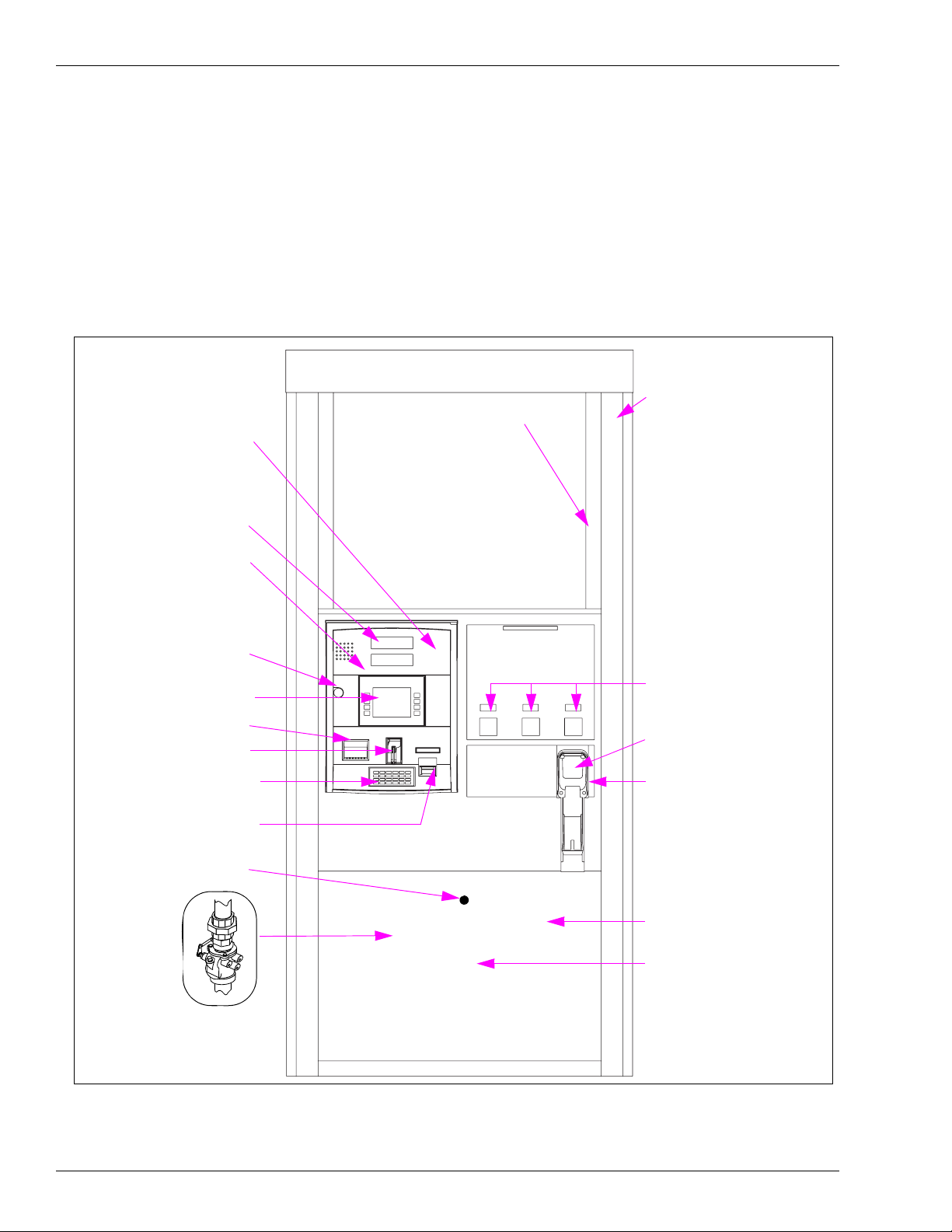
Figure 3-3: Encore S Series Unit
Electro-Mechanical
Totalizer (option) -
Side 1 (the Gilbarco Label is located
on the inner side of the right column,
when facing side 1)
Available but not
Shown
Breakaway
Static Electricity, Health, and Fire
Warnings (recommended location)
Main Door Lock
Main Display
Memo Softkey Panel
Printer Door Lock
CRIND Device Printer
CRIND or PPP Keypad
PPU Displays and Grade
Select Buttons
Security Latch (not shown)
Located below the Main
Door Inside the Lower Panel
Brand Advertising
Panel
Lower Panel
Hose
Brand Decal Area
Main Door
CRIND Display
Manager’s Keypad (not
shown) Located behind
the Main Door
Card Reader Instructions
Card Reader
Nozzle
Lower Panel Door Lock
Shear Valve,
Unions, and Fuel
Filter behind Lower
Panel (not shown)
MDE-3893P Encore® and Eclipse® Series Owner’s Manual · December 2011 Page 9
Page 14
Introducing the Encore/Eclipse Series Encore S Series
Americans with Disabilities Act (ADA) Requirements
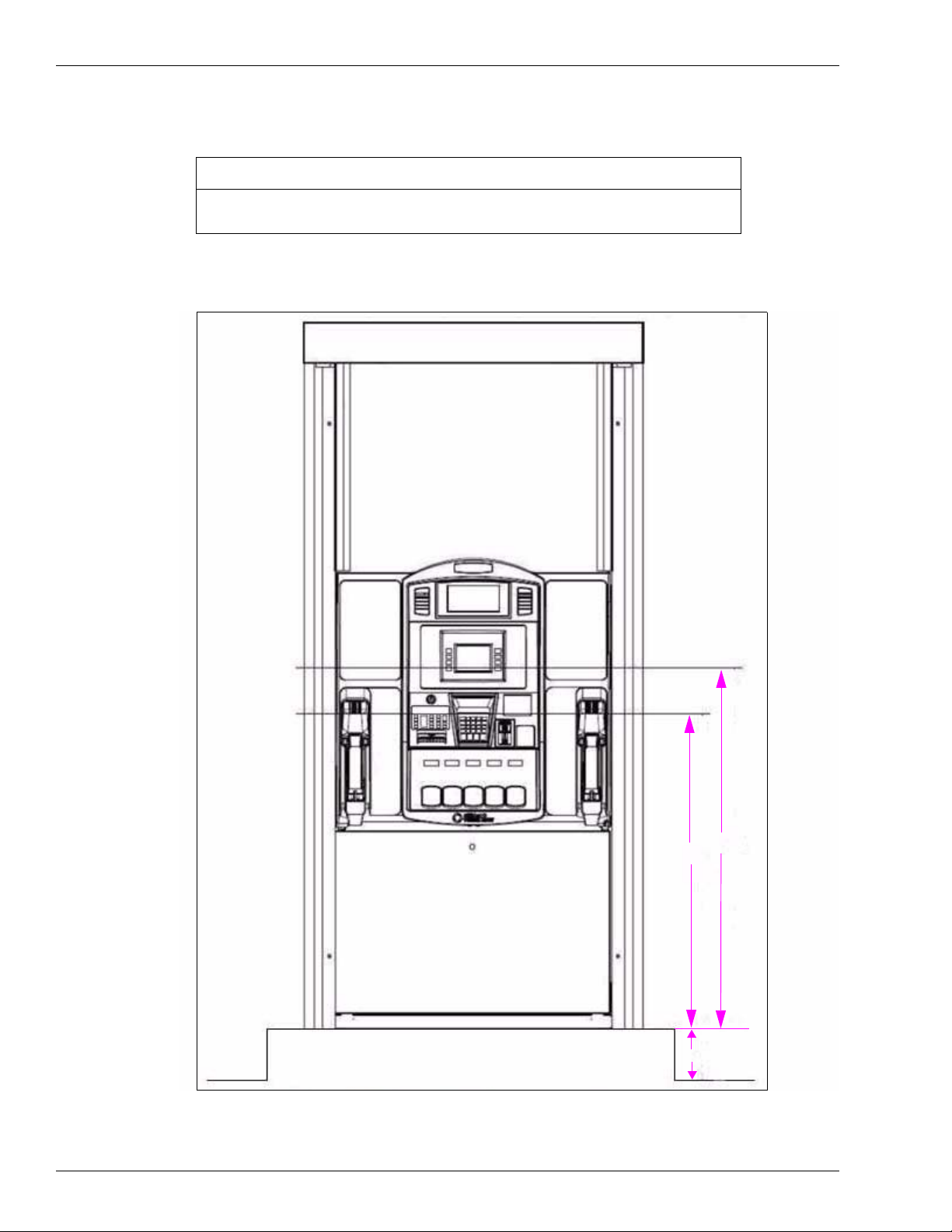
IMPORTANT INFORMATION
To meet the reach requirements as specified by the Americans with Disabilities Act,
the island of the dispenser must not be higher than 6” tall.
Figure 3-4: ADA Requirements
48”
42’
6”
Page 10 MDE-3893P Encore® and Eclipse® Series Own er’s Manual · December 2011
Page 15
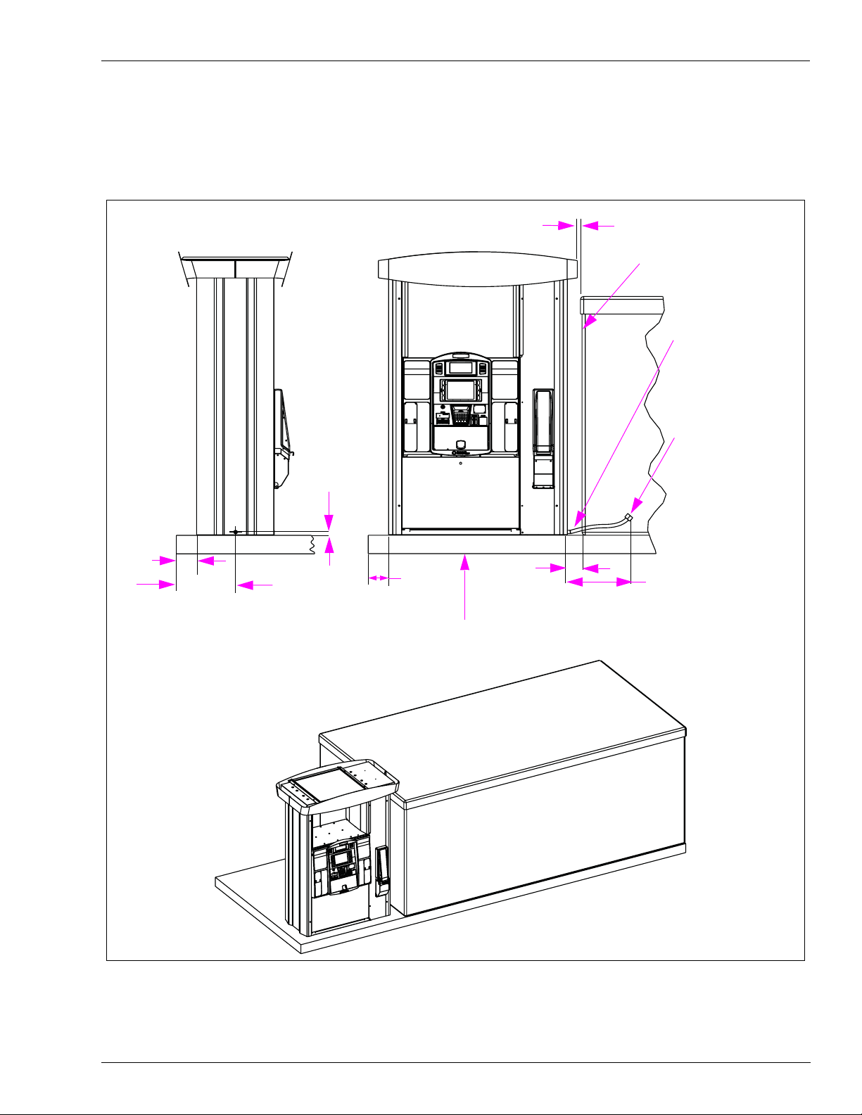
DEF Dispenser Introducing the Encore/Eclipse Series
DEF Dispenser
Figure 3-5: DEF Dispenser (When Tank is not Installed Underground)
(25.0)
[1.0]
Urea Tank
Insulation and/or
Heating Required. Use
solid or foam, non-water
absorbing insulating
materials suitable for
outdoor use.
Urea Inlet 1” BSPP
Female Fitting on the
(29.9)
[1.2]
Dispenser
(160.0)
[6.3]
(308.0)
[12.1]
(160.0)
[6.3]
Skid Common to Both Urea Tank and Dispenser
Typical Skid Tank Install
(115.7)
[4.6]
(2000.0)
[6.5’]
of Hose Length Exposed
MDE-3893P Encore® and Eclipse® Series Owner’s Manual · December 2011 Page 11
Page 16
Introducing the Encore/Eclipse Series Eclipse Series
Eclipse Series
The following illustration shows an Eclipse unit and its components.
Figure 3-6: Eclipse Unit
Discharge
Casting
Hydraulic Access Door Lock
Breakaway
Branding/Advertising
Tuxedo Stripe
Panel (Backlit)
Hose
CRIND Device Display
CRIND Keypad
Card Reader
Cash Acceptor
Lock (not shown)
Manager’s Keypad
(not shown) can be
found behind the Oven
Door
Lower Panel (filter
access) Door Lock
Serial Plate
Lower Panel
Main Display
TRIND Option
PPU Display and Grade
Select Buttons
Oven Door Lock (not shown)
Scanner
Boot Area
CRIND Device Printer
Oven Door
Swivel
Filters, Junction Box,
Shear Valves, and
Unions behind Lower
Panel (not shown)
Page 12 MDE-3893P Encore® and Eclipse® Series Own er’s Manual · December 2011
Page 17

Understanding Date Codes and Serial Numbers Introducing the Encore/Eclipse Series
Understanding Date Codes and Serial Numbers
This section provides information on the date and model codes for the Encore Series and
Eclipse units.
Understanding Date Codes
A two-letter date code is stamped on the serial plate before the Serial Number. This code
shows the month and year of manufacture. Refer to the date code to determine the age of the
equipment for warranty purposes.
To determine the date code on an Encore or Eclipse unit, refer to the following tables.
Month Codes
A = January E = May J = September
B = February F = June K = October
C = March G = July L = November
D = April H = August M = December
Year Codes
J = 2000 N = 2004 T = 2008
K = 2001 P = 2005 U = 2009
L = 2002 R = 2006 W = 2010
M = 2003 S = 2007 X = 2011
Understanding Model Codes
The Model Numbers are located as shown in Figure 3-1 on page 7, Figure 3-2 on page 8,
Figure 3-3 on page 9, and Figure 3-6 on page 12.
For Encore 300/500/550 units, the Model Number uses a two-letter and one-number model
code stamped on the serial plate. For Encore S units, the Model Number uses a two-letter and
a one-number model code listed on the UL Weights and Measures label that is located behind
the printer door.
MDE-3893P Encore® and Eclipse® Series Owner’s Manual · December 2011 Page 13
Page 18

Introducing the Encore/Eclipse Series Understanding Date Codes and Serial Numbers
To determine the model code on a Gilbarco Encore 300, 500 and 550, or Encore S Series unit,
refer to the following table.
Note: Not all models are available in an Encor e 300 (E300) , Encor e 500/5 50 (E500/E550), or
Encore S Series version.
Encore 300, 500/550, and Encore S Series
N X X
Encore A = Multi-hose
Dispenser
C = Multi-hose Pump 0 = 1 Grade
G = Single-hose 0 = 3 Grade Dispenser
J = Multi-hose Blender 0 = 3 Grade Blender Dispenser
L = X+1 Blender 0 = 2 + 1 Grade Blender Dispenser
N = X+0 Blender 1 = 3 + 0 Grade Blender Dispenser
P = Ultra High Flow 3 = Ultra-Hi™ Master
R = Special 0 = No Hydraulics
0 = 1 Grade
1 = 2 Grade
2 = 3 Grade
3 = 4 Grade
4 = DEF only
1 = 2 Grade
2 = 3 Grade
3 = 4 Grade
1 = 3 Grade + 1 Dispenser
2 = 3 Grade Pump
3 = 3 Grade Pump + 1
4 = 2 Grade Single-hose MPD
5 = 2 Grade Single-hose Pump
1 = 3 Grade Blender Pump
2 = 4 Grade Blender + 1 Dispenser
3 = 4 Grade Blender + 1 Pump
4 = 3 + 2 Grade Blender Dispenser
1 = 3 + 1 Grade Blender Dispenser
2 = 4 + 1 Grade Blender Dispenser
3 = 3 + 1 + 1 Grade Blender Dispenser
4 = 2 + 1 Grade Blender Pump
5 = 3 + 1 Grade Blender Pump
6 = 4 + 1 Grade Blender Pump
2 = 4 + 0 Grade Blender Dispenser
3 = 5 + 0 Grade Blender Dispenser
5 = 3 + 0 Grade Blender Pump
6 = 4 + 0 Grade Blender Pump
7 = 5 + 0 Grade Blender Pump
4 = Ultra-Hi Combo
5 = Ultra-Hi Satellite
6 = Ultra-Hi Master Dispenser - Single-sided Dual Product Unit
8 = Ultra-Hi Satellite Dispenser - Single-sided Dual Product Unit
A = Ultra-Hi Master + DEF
B = Ultra-Hi Combo + DEF
1 = Robot
2 = Simulator
3 = Pumpless Pump
4 = No Electronics
Page 14 MDE-3893P Encore® and Eclipse® Series Own er’s Manual · December 2011
Page 19

Common Functions Introducing the Encore/Eclipse Series
Examples:
1 A serial plate stamped “CJ-NA0” contains the following information:
• Date code [CJ]—This unit was manufactured in March 2000.
• Model code [NA0]—This unit is a single-grade, multi-hose, Encore dispenser.
2 A UL Weights and Measures label that lists “CP-NA0” contains the following information:
• Date code [CP]—This unit was manufactured in March 2005.
• Model code [NA0]—This unit is a single-grade, multi-hose, Encore S dispenser.
T o determine the model code on a Gilbarco Eclipse unit, refer to the following table. Note that
not all models are available in an Eclipse unit.
Eclipse Units
E X X
Eclipse G = Single-hose MPD 0 = 3 Grade
L = X + 1 Blender, 4 Hose 0 = 2 + 1 Grade Blender Dispenser
1 = 3 + 1 Grade Blender Dispenser
2 = 4 + 1 Grade Blender Dispenser
3 = 5 + 1 Grade Blender Dispenser
N = X + 0 Blender, 2 Hose 0 = 2 + 0 Grade Blender Dispenser
1 = 3 + 0 Grade Blender Dispenser
2 = 4 + 0 Grade Blender Dispenser
3 = 5 + 0 Grade Blender Dispenser
Example:
A serial plate stamped “GM-EN1” contains the following information:
• Date code [GM]—This unit was manufactured in July 2003.
• Model code [EN1]—This unit is a three-grade , two-hose, Eclipse blender dispenser.
Common Functions
This section provides information on the common functions of the Encore Series and Eclipse
units.
Displaying the Last Transaction
If power supply is interrupted, information about the previous sale (last transaction) remains
visible on the main display for at least 15 minutes.
MDE-3893P Encore® and Eclipse® Series Owner’s Manual · December 2011 Page 15
Page 20
Introducing the Encore/Eclipse Series Common Functions
Displaying Pump Totals for Encore/Eclipse Units
You can view pump totals for Encore and Eclipse units on the main and Price Per Unit (PPU)
displays by using the Manager’s Keypad located behind the Customer Interface Module (CIM)
door or Oven door on Side 1 of the dispenser. The keypad’s magnetic backing allows easier
handling and input.
Notes: 1) For Encore 300/500/550 and Eclipse units, to identify Side 1 (A) of the pump or
dispenser, refer to the section titled “Programming Orientation” in MDE-4732
Encore and Eclipse Series Owner’s Programming Manual.
2) For Encore S Series units, to identify Side 1 of the unit, see Figure 3-3 on page 9.
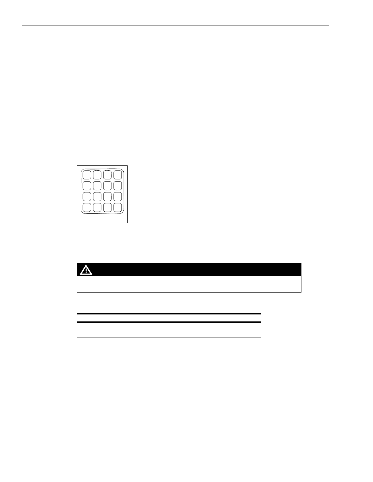
The Manager’s Keypad is as shown in Figure 3-7.
Figure 3-7: Manager’s Keypad
1
2
3
F1
4
5
6
F2
7
8
CLEAR
0
Manager’s Keypad
9
ENTER
TOTAL
VOL
TOTAL
$
Note: To enter the Command Codes required to place the pump/dispenser in Standalone
mode or to program prices directly at the unit, refer to “Standalone Mode” on
page 19.
WARNING
To avoid potential electric shock, do not touch any wiring or electronic component(s)
behind the CIM/Oven Door or Main Door.
The following table explains how to access the Manager’s Keypad.
For this Model Series Use these Steps to Locate the Manager’s Keypad
Encore 300/500/550/S Series • Open CIM door on Side 1 (A)
• Keypad is attached (by magnet) behind the door
Eclipse • Open Oven door on Side 1 (A)
• Keypad is attached (by magnet) behind the door
Page 16 MDE-3893P Encore® and Eclipse® Series Own er’s Manual · December 2011
Page 21
Common Functions Introducing the Encore/Eclipse Series
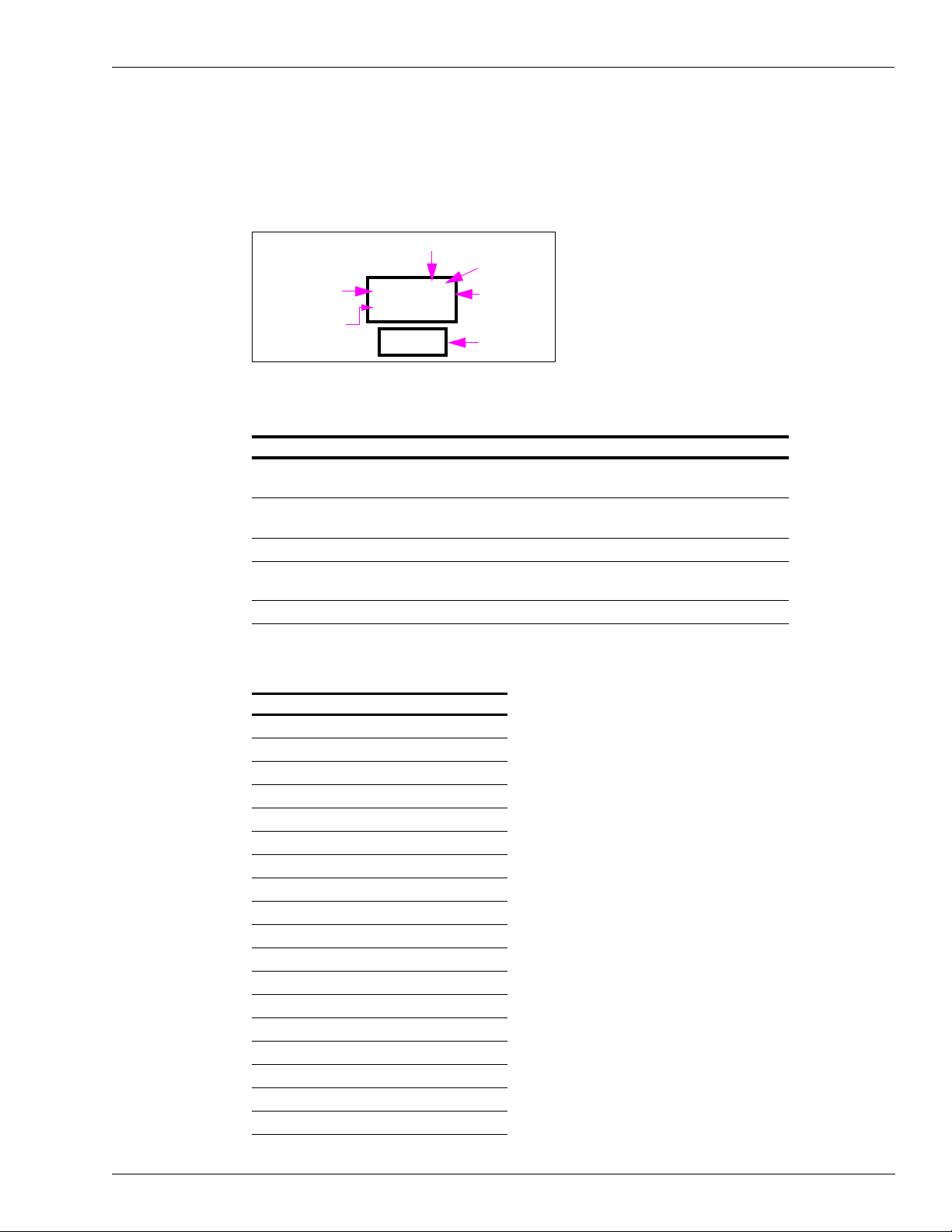
The location of data in the displays is shown in Figure 3-8.
Note: To see illustrations that show the location of these displays, refer to
“Introducing the Encore/Eclipse Series” on page 7.
Figure 3-8: Location of Data
Side
Grade
Money Display
Volume Displ ay
1 2 3 4 5 6
1 2 3 4 5 6
1 2 3 4
Main Display
PPU Display
Use the Manager’s Keypad and the instructions in the following table to display pump totals
for Encore and Eclipse units.
To Press Result
Display totals • $Total for Money
• Vol Total for Volume
Select side • 1—Side 1 (A)
• 2—Side 2 (B)
Select grade ENTER and 1-8 for grades 1-8. Grade digit flashes
Toggle between side and grade ENTER Toggles flashing digit between
Exit CLEAR Exits the operation
Side digit flashes
Side digit flashes
side and grade digit
Grade Number Reference Chart
Type Grade
Encore 300
Dual 1
Quad (Four-hose) 1, 2
Multi-Product Dispenser (MPD) 1, 2, 3
6H Bl 1, 2, 3
3 + 0 Bl 1, 2, 3
3+1 Bl 1, 2, 3, 6
5+0 Bl 1, 2, 3, 4, 5
Encore 500
Dual 1
Quad 1, 2
MPD 1, 2, 3
3 + 0 Bl 1, 2, 3
6H Bl 1, 2, 3
4 Grade MPD 1, 2, 3, 4
5 + 0 Bl 1, 2, 3, 4, 5
3 +1 Bl 1, 2, 3, 6
MDE-3893P Encore® and Eclipse® Series Owner’s Manual · December 2011 Page 17
Page 22

Introducing the Encore/Eclipse Series Common Functions
Type Grade
Encore 550
3 + 0 Bl 1, 2, 3
Multi-hose Bl 1, 2, 3
MPD 1, 2, 3, 4
Single-hose 1, 2, 3, 4
4 + 0 Bl 1, 2, 3, 4
5 + 0 Bl 1, 2, 3, 4, 5
2 + 1 Bl 1, 2, 6
3 + 1 Bl 1, 2, 3, 6
Multi-hose+1 Bl 1, 2, 3, 6
4 + 1 Bl 1, 2, 3, 4, 6
Encore 500 S
Dual 1
Quad 1, 2
MPD 1, 2, 3
3 + 0 Bl 1, 2, 3
6H Bl 1, 2, 3
4 Grade MPD 1, 2, 3, 4
5 + 0 Bl 1, 2, 3, 4, 5
3 +1 Bl 1, 2, 3, 6
3 + 0 Bl 1, 2, 3
Multi-hose Bl 1, 2, 3
MPD 1, 2, 3, 4
Single-hose 1, 2, 3, 4
4 + 0 Bl 1, 2, 3, 4
5 + 0 Bl 1, 2, 3, 4, 5
2 + 1 Bl 1, 2, 6
3 + 1 Bl 1, 2, 3, 6
Multi-hose+1 Bl 1, 2, 3, 6
4 + 1 Bl 1, 2, 3, 4, 6
Eclipse
2 + 0 Bl 1, 2
MPD 1, 2, 3
3 + 0 Bl 1, 2, 3
4 + 0 Bl 1, 2, 3, 4
5 + 0 Bl 1, 2, 3, 4, 5
2 + 1 Bl 1, 2, 6
3 + 1 Bl 1, 2, 3, 6
4 + 1 Bl 1, 2, 3, 4, 6
5 + 1 Bl 1, 2, 3, 4,
5, 6
Page 18 MDE-3893P Encore® and Eclipse® Series Own er’s Manual · December 2011
Page 23

Operating the Units Introducing the Encore/Eclipse Series
Operating the Units
The Encore and Eclipse units can dispense fuel in one of the following two modes:
• Console mode (Two-wire) - Authorization and payout occurs at the console
• Standalone mode - Authorization and payout occurs at the pump
This section provides instructions for operating the units in either mode.
Note: For the location of components, refer to the illustrations in “Introducing the Encore/
Eclipse Series” on page 7.
Console Mode (Two-wire)
Consoles can be set up in a pre-authorized mode where a sale is automatically allowed, or in
an authorization mode where a sale requires initiation by a cashier.
To operate a unit in authorization mode, proceed as follows:
Note: Step 1 can occur before or after steps 2 and 3.
1 Authorize the unit at the console.
2 Remove the nozzle and lift the pump handle, if required.
3 Select the grade and/or payment form, if required.
4 Dispense the fuel.
5 Return the nozzle to the nozzle boot.
6 Pay out the fuel transaction at the console.
Standalone Mode
Standalone mode does not involve the console with the sale. To operate a unit in a
pre-authorized mode, proceed as follows:
1 Remove the nozzle and lift the pump handle, if required.
2 Select the grade and/or payment form, if required.
3 Dispense the fuel.
4 Return the nozzle to the nozzle boot.
MDE-3893P Encore® and Eclipse® Series Owner’s Manual · December 2011 Page 19
Page 24

Introducing the Encore/Eclipse Series Operating the Units
This page is intentionally left blank.
Page 20 MDE-3893P Encore® and Eclipse® Series Own er’s Manual · December 2011
Page 25

Important Considerations for DEF Dispensers Preparing to Service Units
4 – Preparing to Service Units
This chapter provides instructions for collecting information on any unit-related problems that
a Gilbarco-trained Authorized Service Contractor (ASC) or Customer Specified Contractor
(CSC) will require for servicing. Providing complete information can shorten the time
ASCs/CSCs spend troubleshooting the problem and enable them to have the correct parts
required for service.
WARNING
Do not attempt to service an Encore or Eclipse pump/dispenser yourself without special,
qualified training. Servicing an Encore or Eclipse pump/dispenser incorrectly could result in
severe injury or death. Only Gilbarco-trained ASCs/CSCs must service an Encore or
Eclipse pump/dispenser.
WARNING
Do not make unapproved modifications to Gilbarco equipment. Doing so could result in
improper equipment operation and violation of state and local codes, and could also create
a safety hazard. Consult your ASC/CSC, distributor, or Gilbarco for approved modifications
and kits.
Important Considerations for DEF Dispensers
CAUTION
Applicable during Installation and Operation of the Dispenser: DEF freezes at approximate ly
-11.5 °C (11 °F). Power to the dispenser and heater must always remain ON in cold weather. If
power is lost and the temperature drops below this point, the system must be inspected for freeze
damage before restart. For sites that experience occasional power losses or for sites that are
located in very cold climates, it is recommended that a backup power generator be used to
maintain constant power to the dispenser. Do not use any additives to lower the freezing point of
DEF. Additives of any type must not be used in DEF. Freezing can cause damaged or inoperative
hose breakaways, fluid lines or components, valves, nozzles and meters.
Prolonged storage at temperatures above 25 °C (77 °F) can impair the quality of DEF and reduce
its shelf life.
CAUTION
DEF is mildly corrosive. It can corrode components that are made from incompatible materials and
reduce their integrity. The use of incompatible materials may lead to leaks and spills, and can
contaminate and degrade the DEF. When dispensing DEF, verify with the manufacturer if the
material of all plumbing components are compatible with the DEF being dispensed.
MDE-3893P Encore® and Eclipse® Series Owner’s Manual · December 2011 Page 21
Page 26

Preparing to Service Units Important Considerations for Units with Ecometers
CAUTION
Do not use Prover Cans meant for engine fuel with DEF or vice versa. Use stainless steel Prover
Cans for DEF. DEF and engine fuel must not be mixed with each other or contaminated by each
other. Else, damage to a vehicle’s engine or pollution control devices could occur. DEF crystallizes
as its water base evaporates. Pouring out liquid will not guarantee that no corrosive DEF remains
in the Prover Can. DEF must not be contaminated with Diesel fuel, contaminants, or other fluids or
materials. Such contamination can cause serious damage to vehicle catalytic converters.
• Conventional fluid handling precautions are also applicable to DEF.
• DEF is non-flammable and not explosive.
• When exposed to air, the water in DEF will evaporate and result in development of urea
crystals. Crystals may be fine and sharp. They will dissolve in water
• Clean any DEF spill with water and dry the area with clean rags, especially areas that
contain metallic parts. Ensure that spilled DEF does not re-enter the tank. Spilled DEF can
be slippery and will corrode metallic parts. Wear eye protection and rubber gloves during
any cleanup activity.
• DEF can be returned to the storage tank only if it is not contaminated. Contaminated DEF
must be disposed off in an environmentally safe manner. Do not dump DEF in storm
sewers or any location where the fluid or its constituents may enter a waterway.
• DEF is much heavier than fuels such as gasoline. Be careful to avoid injury when lifting
heavier Prover Cans, by using proper safe lifting techniques.
WARNING
When stored at temperatures above 37 °C (100 °F), DEF may break down into ammonia.
Ensure that you avoid inhaling any toxic ammonia vapors when opening cabinets, tank
vaults, or other areas where DEF may have leaked or been spilled.
WARNING
DEF can cause serious eye injury if sprayed in the eyes or may affect those with sensitive
skin. Wear protective gloves and eye protection as required. Flush eyes immediately with
water, if sprayed.
Ensure that eyewash stations and safety showers are close to the workstation location.
Important Considerations for Units with Ecometers
Units must always use the M008007B010 (gasoline) or M08007B030 (diesel) filter
®
manufactured by PetroClear
To maintain warranty, the unit requires use of a special filter type as mentioned above. It
potentially allows lesser contaminant to pass through it during normal unit operation as
compared to other filters and prevents nozzles from snapping shut. The filter has a standard
mounting and is similar in cost to current filters. The filter contains a slightly higher load
spring. In addition, it has improved internal sealing. The filter will also potentially improve the
reliability of other hydraulic devices in the dispenser such as valves.
filter.
Page 22 MDE-3893P Encore® and Eclipse® Series Owner’s Manual · December 2011
Page 27

Important Considerations When Changin g Fuel Types Preparing to Service Units
Important Considerations When Changing Fuel Types
WARNING
Certain special alternative fuels such as E85 and additives can degrade pump/dispenser
performance or integrity if the dispensers are not designed for use with such fu els.
Additionally, converting to certain standard fuels (gasoline, diesel, kerosene, and so on)
from alternative fuels such as those with ethanol (E85), methanol, or Biodiesel or from
alternative fuels to standard fuels can degrade dispenser performance or integrity. Similar
effects can also occur when converting units to different standard fuel types. As per
UL 87A requirements, units dispensing E85 fuel must not be used to dispense any
other type of fuel such as Gasoline.
Leaks and potential environmental hazards can result or components may fail prematurely.
To avoid these issues, follow the guidelines as described in this section.
Follow the guidelines given below when changing fuel types for a pump/dispenser or using
alternative fuels or fluids:
1 Verify with your Gilbarco ASC or Distributor if the fuel that you will use is compatible with
the pumps/dispensers that dispense the fuel.
2 For Flexible Fuel (FF) dispensers, do not use standard hydraulic parts used in other Gilbarco
pumps/dispensers in these units. Standard dispenser parts may not be compatible with the
fluids.
3 Biodiesel fuels must be to ASTM standards for Biodiesel fuels. Mixes of diesel with cooking
oils, other plant or animal derived oils, and so on are not considered Biodiesel. Use of such
mixes may void warranty on the hydraulic components of the un it.
4 Review the latest copy of the unit’s warranty statement regarding use of the fuel.
5 Certain fuels (especially fuels enhanced with alcohol) when first used in tanks previously
containing a different fuel may clean out the tanks and force a large amount of contaminant
into the dispenser. Apart from abnormally clogging filters, this large quantity of contaminant
may damage certain dispenser components. Do not run units without filters at such times. It is
normally required that tanks and lines be cleaned of all water, sediment and contaminant
before such conversions, to minimize potential unit downtime or damage. Damage to
hydraulic components from contamination when not using filters is not covered by warranty.
Consult your ASC or Gilbarco Distributor for recommendations.
6 Do not use any equipment that was formerly used to store or dispense any other fuel or liquid
with DEF. Dispensers designed for use with DEF must only be used with DEF.
7 Although conversions from one fuel to an equivalent fuel (say from another supplier)
generally do not create issues, it is recommended that after making any fuel type conversions
(including those to alternative fuels such as E85 or back), all units be visually inspected for
leaks two days, one week, and one month after fuel conversion. Have your ASC repair any
leaks found. This must be done also for standard fuels when significant new additives are
incorporated.
Note: This does not apply to Flexible Fuel model dispenser s.
MDE-3893P Encore® and Eclipse® Series Owner’s Manual · December 2011 Page 23
Page 28

Preparing to Service Units Dispensing Gasoline/Ethanol Blends
8 It is recommended that whenever making non-equivalent fuel conversions, all units be
checked for calibration within one month after the fuel conversion.
9 Some non-equivalent fuel conversions must change the pump/dispenser filter type previously
used. For any changes required, consult your ASC or Gilbarco Distributor.
Dispensing Gasoline/Ethanol Blends
The blending option provided on these dispensers is intended for the blending of
Gasoline/ethanol blends designated as E85 with gasoline or gasohol (E10 maximum) to
achieve an intermediate gasoline/ethanol blend.
IMPORTANT INFORMATION
Standard gasoline or Gasohol (E10 maximum) must not be dispensed through the
same hose as that used for dispensing higher ethanol blend fuels (E11 to E85).
Important Requirements for E85 Units
The following equipment and materials are required to properly service the E85 units:
UL-listed E85 Hose (Q13486)
• VeyanceSM Flexsteel® Futura™ Ethan-All for E85
• Veyance Flexsteel Futura for E25
Note: Extended Reach hoses not available for the E85 applications.
UL-listed E85 Nozzle (M11298)
OPW 21GE
Note: Approved for use with the E85 dispensers, as required under UL 87A.
UL-listed E85 Swivel (N23748-04)
OPW 241 TPS-0492
Note: Approved for use with E85 dispensers, as required under UL 87A.
UL-listed E85 Shear Valve (T19695-23)
OPW 10P-0152E85
Note: Approved for use with E85 dispensers, as required under UL 87A.
UL-listed E85 Breakaway (N23010-10)
OPW 66V-0492
Note: Approved for use with E85 dispensers, as required under UL 87A.
Filter
Use only filters specifically marked for use with E85.
UL-listed Pipe Sealant
Use only UL-listed TPS PTFE Pipe Sealant manufactured by SAF-T-LOC International Corp.
UL-listed Teflon® Tape
Use only UL-listed Taega Technologies Inc. Teflon tape.
Note: Teflon tape must be used only at the inlet pipe connection.
Page 24 MDE-3893P Encore® and Eclipse® Series Owner’s Manual · December 2011
Page 29

Call Gilbarco First Preparing to Service Units
Call Gilbarco First
Before calling an ASC/CSC, call the Gilbarco Help Desk at 1-800-800-7498. The Help Desk
may be able to resolve the issue for you.
Service Preparation
Use an ASC/CSC to efficiently service and maintain your Encore and Eclipse units. Gilbarco
trains and certifies ASCs/CSCs to service and maintain Encore and Eclipse units in a safe
manner. Warranty service must be performed by an ASC/CSC only.
Before Making a Service Call
Before you make a service call, perform the following tasks:
• Obtain complete information from station personnel about the problem. Provide any
history that may help (whether the unit has a recurring problem, or the problem has been
observed for the first time, and so on).
• M ention the associated hose number(s) along with the problem.
• Confirm that the tank has fuel.
• Confirm that the power, pump lights, and circuit breakers are on.
• For electronic units, write down and report any error codes displayed.
Note: For information on recording and clearing error codes, refer to “Error Codes” on
page 29.
Description of the Problem
Provide the ASC/CSC with a complete and accurate description of the problem, including all
symptoms and error codes. Ensure that you give the service personnel as complete and
accurate information as possible. It will help ensure faster and potentially less costly repairs
and keep downtime costs to a minimum.
Warranty Service
IMPORTANT INFORMATION
All warranty service must be performed by an ASC/CSC. Failure to use an ASC/CSC
to perform warranty service could result in loss of warranty coverage.
Station Security
In any manufacturer’s unit, it may be impossible, even with a detailed security arrangement,
to stop a knowledgeable, unobserved, and experienced thief. It is possible to reduce the
probability of a theft attempt, if security measures are designed into the station layout and
security-minded actions are planned into the site’ s operation. The following recommendations
are intended to decrease the probability of theft by observance and/or incorporating obstacles
that deter criminal activity.
MDE-3893P Encore® and Eclipse® Series Owner’s Manual · December 2011 Page 25
Page 30

Preparing to Service Units Station Security
Enhancing Security
To enhance security, proceed as follows:
1 Design stations where employees have full, unobstructed view of all fueling locations. Do not
block employee view with merchandise displays or other obstructions. If full view is not
possible, utilize video surveillance equipment. Equipment monitoring must be made obvious
and signs stating their use must be posted.
2 Enter new programming access code, as default codes are commonly known. Only trusted
station employees and involved ASCs/CSCs must know these codes. Store the codes in a safe
and secure location known to all station management personnel. Unit service can be costlier , if
these codes are lost.
3 Use unit security kits when available. For areas subject to high risk of theft, consider the
additional security of special keys/locks to replace the standard locks. Such keys and locks can
be obtained from local locksmiths. This enhancement is extremely effective in preventing theft
modes using the keypad with the additional benefits of preventing potential tampering with
other dispenser devices.
4 Remove the keypads from the units and store them in the station or other safe locations. The
keypads must be accessible to station management or service people when required. A sign out
system can be used to track who last used the keypad.
5 Suggest that the station monitor “pump total” and “station total” reports comparatively. Theft
can be noted as fuel dispensed will still be recorded in “pump totals” (although not in “station
totals”), if a thief use the Manager’s Keypad. When this will not prevent the theft that has
already occurred, it will alert the station as to whether security measures are working or must
be applied.
6 Plan to use modular programming “time-out” functions that shut down the unit if no pulser
activity occurs for a preselected time. Consult your ASC and determine if there is any optional
software that can be used on your units to enhance security.
7 Remind station personnel to be alert to any unit off-line message at the POS, accompanied by
suspicious activity at the pump/dispenser.
8 Plan to provide periodic/frequent inspection of equipment security provisions to verify their
integrity.
9 At installation and thereafter, ensure that lower door levers are adjusted correctly and do not
allow the panels to be removed easily without a key or tool. If you suspect that keys are
available to thieves in your area, consider using special locks and keys available from
locksmiths.
10 Be alert to dispensers being “off-line” or equivalent at the POS. Fuel theft could be occurring
especially if the customer is pumping fuel.
11 For units left powered during off hours, ensure that power to the Submersible Turbine Pumps
(STPs) is turned off.
Page 26 MDE-3893P Encore® and Eclipse® Series Owner’s Manual · December 2011
Page 31

Additional Security in Encore S Series Units Preparing to Service Units
Additional Security in Encore S Series Units
The Encore S series units have been designed with security in mind to prevent/minimize the
probability of fuel theft.
In addition to security features that have been built into the Encore units so far, such as the
CIM, lower panel locks and keys, and the Personal Identification Number (PIN) code-secured
Manager Keypad, the Encore S series unit comes with the following additional security
features:
• A separate printer door (with a lock) that restricts access to the inside of the unit.
• A security latch that may be used to secure the lower part of the main door (bezel). See
Figure 4-1 on page 28.
• An improved design that does not enable a person to open the main door without first
removing the lower panel door.
• An option to install hinge sensors that will send an alert to the POS whenever the
main/lower panel doors are opened.
To optimally utilize the additional security features installed in the Encore S series units,
proceed as follows:
1 Close and lock the main door, using the main door lock located to the left of the main door. T o
identify the location of the lock, see
Notes: 1) When closing the main door, remember to push inward and then lock the door to
ensure that the inner lining is sealed to prevent rain water from seeping into the
main door.
2) If you do not close the main door properly, you will have problems when removing or
reinstalling the lower panel door.
2 Place the security latch in the locked position.
Note: You may use a padlock (optional) to secure the latch.
Figure 3-1 on page 7.
MDE-3893P Encore® and Eclipse® Series Owner’s Manual · December 2011 Page 27
Page 32

Preparing to Service Units Additional Security in Encore S Series Units
3 Place the lower panel door and lock it using the lower panel lock.
Figure 4-1: Security Latch - Open and Locked Positions
Place for
Padlock
(optional)
Open Position Locked Position
Notes: 1) If you suspect that the main/printer/lower panel door key’s security has been
compromised, consider purchasing replacement locks for the units from Hudson
Lock Inc. (www.hudsonlock.com). Ordering directly from the lock supplier will
ensure a strict control over the distribution of locks and keys, eliminating the
possibility of keys being taken or copied through the traditional distribution
channels. Hudson Lock can provide specific pricing and lead-time information
based on the requirements. You may contact Hudson Lock at 1-800-434-8960.
2) ASCs must be aware of any lock changes or added locks in order to service the unit.
The keys must be available to the ASCs.
Important Installation Information
To ensure that your equipment provides safe and reliable operation, verify the following:
• Hose breakaways for drive-off protection must be installed. For breakaways to properly
function, the pumps must be anchored to the island with bolts.
• Dispensers and some self-contained pumps must use Shear Valves. Refer to the local and
state codes.
• Proper operating and safety warning signs must be used at the station. Refer to the local
and state codes and consult the oil company.
• Station emergency stop buttons must be used. Refer to the state and local codes.
• Isolation relays must be used with dispensers. Refer to the national, state, and local codes.
• S hear Valve linkage must be free of obstructions so that the valve can close properly
during a fire or accident.
• Ensure that the installers follow all other requirements and recommendations in
MDE-3802 Encore & Eclipse Site Prep Manual, MDE-3985 Encore Installation Manual,
and MDE-3986 Eclipse Installation Manual.
Page 28 MDE-3893P Encore® and Eclipse® Series Owner’s Manual · December 2011
Page 33

Additional Security in Encore S Series Units Preparing to Service Units
Unit Commissioning
Unit commissioning is a valuable service included in the purchase price of most dispensers.
During commissioning, the ASC/CSC inspects and verifies if the units have been properly
installed and operate as intended. Some unit training is also given to stati on employees as part
of the process. You must ensure that the units are commissioned shortly after installation.
Improper installation can void warranty or result in poor unit performance.
Error Codes
If an error or malfunction occurs, the LCD on the main display may flas h and alternately
display the error code and the normal readout. Some error codes can appear at the PPU. These
must not be confused with numbers that may flash when power is first applied to the unit.
These numbers represent software versions and other similar information, and are not error
codes.
Recording Error Codes
Error codes provide an excellent service and troubleshooting tool for ASCs/CSCs and will
ensure that the ASC/CSC brings the correct part to the site for a quick repair. Record all error
codes and provide the list to your ASC/CSC. The ASC/CSC uses these codes to diagnose and
repair unit problems, which results in less down time.
Clearing Error Codes
In some cases, you can permanently clear error codes from the unit. To clear an error code,
proceed as follows:
1 For EC 44 - pump handle on at power up, replace handle, power down, and then power up.
One instance of this error code does not normally require a service call.
2 If the error code still appears, power down the unit, wait for one minute, and then restore
power using the station circuit breaker.
3 If the error code still appears or reappears at a later time, record the error code and call your
ASC/CSC for assistance.
Replacement Parts
Use only genuine Gilbarco replacement parts and retrofit kits on your unit.
Only use Gilbarco replacement parts and retrofit kits. Non-Gilbarco replacement parts may
create safety hazards and violate local regulations.
Gilbarco replacement parts are required to maintain warranty.
WARNING
MDE-3893P Encore® and Eclipse® Series Owner’s Manual · December 2011 Page 29
Page 34

Preparing to Service Units Additional Security in Encore S Series Units
Specialized Training
For safety reasons, do not attempt to service an Encore or Eclipse unit yourself, unless you
have been trained and certified to do so.
WARNING
Do not attempt to service an Encore or Eclipse pump/dispenser yourself. Only a
Gilbarco-trained ASC/CSC must service an Encore or Eclipse pump/dispenser. Servicing
an Encore or Eclipse pump/dispenser incorrectly could result in severe injury or death.
T o receive specialized training for servicing Encore and Eclipse units, contact an ASC/CSC or
distributor. Training may be available locally or at various regional centers.
ASCs/CSCs and distributors may charge a nominal training fee. For more information, contact
your nearest distributor.
Page 30 MDE-3893P Encore® and Eclipse® Series Owner’s Manual · December 2011
Page 35

General Safety Considerations Maintaining Units
5 – Maintaining Units
This chapter provides information on the following aspects of pump/dispenser maintenance:
• Periodic Inspections
• P eriodic Maintenance Requirements
• Special Maintenance Instructions
CAUTION
DEF is mildly corrosive. To avoid damage to components in the vicinity of the
dispenser, avoid use of materials that could be corroded, or use protective
coatings.
CAUTION
Do not open the electronics cabinet to change paper, to remove cash acceptor
cassettes, or to perform any other tasks when it is raining. The moisture from the
rain can damage the pump/dispenser.
General Safety Considerations
Safe operation of the equipment is very important to your customer and you. The following
recommendations are in addition to those found in the sections that follow and
Safety Information” on page 3.
1 Do not allow the customer to use damaged units or broken components with sharp edges.
2 Do not allow the customer to use units with missing doors or panels or with doors open.
3 Ensure that the adequate and readable instructions are clearly given on the units or nearby
areas for potential safety hazards such as static electricity fueling hazards, use of unapproved
containers, and so on. Place signs where fueling customers will notice and can read them.
4 Do not use long hoses beyond recommendations that may present a trip hazard. Use hose
retrievers in good operating condition, when long hoses are used.
5 Do not allow the customer to use units which do not have hose breakaways installed on them .
6 Do not allow the customer to use units with hoses and/or nozzles removed from either side.
“Important
MDE-3893P Encore® and Eclipse® Series Owner’s Manual · December 2011 Page 31
Page 36

Maintaining Units Periodic Inspections
7 Do not allow the customer to use units that are leaking fuel.
WARNING
DEF, flexible fuels such as Biodiesel, high alcohol percentage fuels such as E85, and so on
may be incompatible with certain plumbing materials and hydraulic components.
Use of incompatible materials or components with alternative fuels such as E85 or DEF can
result in leaks or unexpected failures of components resulting in fire or explosion or
environmental damage. When installing components in E85 units, refer to “Important
Requirements for E85 Units” on page 24.
When dispensing alternative fuels such as E85 or DEF, verify with the manufacturer if the
material of all plumbing components are compatible with the fuels or DEF being dispensed.
Periodic Inspections
Performing General and Component Maintenance Inspections
This section provides instructions for scheduling two types of maintenance inspections:
• General inspe ctions
• Component inspections
Note:This section does not include special inspections such as those require d when changing
fuel types. For those requir ements, refer to
“Important Considerations When Changing
Fuel Types” on page 23.
Safety Warnings
You are performing inspections and maintenance in a potentially dangerous environment of
flammable fuels/vapors and high voltage. To prevent injury when inspecting a unit at the
islands, follow all safety precautions in
“Important Safety Information” on page 3.
WARNING
You are performing inspections and maintenance in a potentially dangerous environment
of flammable fuels/vapors and high voltage. Failure to adhere to the safety precautions in
this manual may cause fire or explosion, resulting in severe injury or death. Read and
adhere to all safety precautions before performing any maintenance activity.
General Inspections
Perform a general inspection of each unit as follows:
• Every week to ensure that all units are operating properly
• Whenever you receive a complaint about potential unit problems
Page 32 MDE-3893P Encore® and Eclipse® Series Owner’s Manual · December 2011
Page 37

Periodic Inspections Maintaining Units
As part of your general inspection, inspect the entire pump or dispenser for the following
indications:
• External damage
• Leaks
• Exposed sharp or similar edges that may cause cuts
• M issing parts, doors, and so on.
• Safety hazards when fueling, such as slippery surfaces, trip hazards, missing warning
signs, and so on.
Replace any missing or damaged warning labels. Gilbarco also strongly recommends that
ASCs/CSCs periodically inspect the equipment as outlined in the next subsection.
WARNING
If you find any leaks or damage, stop using the pump/dispenser, and contact your local
ASC/CSC. Fire, explosion, or electrical shock could result, if you continue to use leaking or
damaged pumps/dispensers.
WARNING
To prevent injury to customers or yourself, block customer access to the pump/dispenser
with cones or similar equipment, when inspecting.
Component Inspections
To schedule component inspections, refer to the following table. Generally, the station owner
must only inspect for damage or problems with the units. For safety reasons, several tasks in
the following table, including all repairs, must be performed only by an ASC/CSC. To
determine if an ASC/CSC must perform a task, refer to the column titled
“Who Performs the
Inspection/Repair” in the following table.
WARNING
Do not attempt to perform any task that is noted “ASC/CSC only” in the “Who Performs the
Inspection/Repair” column. Performing those tasks incorrectly could result in severe injury
or death.
WARNING
If you find a leak during an inspection, stop using the pump/di spenser, and contact your
local ASC/CSC. Fire, explosion, or electrical shock could result, if you continue to use a
leaking or damaged pump/dispenser.
MDE-3893P Encore® and Eclipse® Series Owner’s Manual · December 2011 Page 33
Page 38

Maintaining Units Periodic Inspections
"
Recommended
Frequency
Once a month Belts Recommended Belt Tensions:
Components Recommended Maintenance
Tighter belt tensions can cause wear and premature
failures for both pump and motor bearing. Loose
belts result in low flow or pulley/belt failures. Use the
following ratings:
• 65-75 lbs (30-34 Kgf) for new belts
• 50-65 lbs (28-30 Kgf) for old belts
Who Performs the
Inspection/Repair
• Owner—Inspect
• ASC/CSC only—Repair
and test
CAUTION
Belts and pulleys can pinch fingers and hands.
Injuries may result. Avoid placing fingers or hands
between belts and pulley. Never turn power on to fit
belt on pulley.
1. On the link belts, check all tabs for correct
positions (inward).
2. Check the belt tension. If there is more than one
inch of play on one side of belt, then tighten the
belts by tightening the idler pulley against the belt.
If there is excessive play, then replace the belt
with the next shorter length belt
11"
Upon receiving a
customer
complaint
Upon receiving a
customer
complaint
Once a week Displays 1. Inspect displays for proper reading of all digits.
Replacing
printer paper
Correcting
printer jams
Refer to the instructions in “Changing the Receipt
Paper in the M00317A00X Printer” on page 45 or
“Changing the Receipt Paper in USB Printer
(M04119A001)” on page 48 or “Changing the
Receipt Paper in USB Sliding Printer
(M06972A001)” on page 51 or “Changing the
Receipt Paper in USB Sliding Printer for Encore S
Series Enhanced Bezel (M07885A001)” on page 55.
Refer to the instructions in “Clearing Paper Jams in
USB Printer (M04119A001)” on page 59 or “Clearing
Paper Jams in USB Sliding Printer (M06972A001)”
on page 61.
2. Verify if the displays are properly backlit.
Owner
Owner
• Owner—Inspect
• ASC/CSC only—Repair
and test
Page 34 MDE-3893P Encore® and Eclipse® Series Owner’s Manual · December 2011
Page 39

Periodic Inspections Maintaining Units
Recommended
Frequency Components Recommended Maintenance
At least once a
week or if a
customer
complaint arises
Hoses 1. Inspect each hose for leaks and damage. • Owner—Inspect
WARNING
If you find a leak, stop using the pump/dispenser, and contact
your local ASC/CSC. Fire, explosion or electrical shock could
result, if you continue to use a damaged pump/dispenser.
2. Inspect each hose for the following wear or
damage:
• Bulges
•Cracks
•Cuts
• Flattened spots
• Reinforcement showing
• Soft spots
•Splits
• Weaknesses
• Tears
3. Consult the hose manufacturer for any additional
inspections required.
Note: If repair is required, call an ASC/CSC.
Who Performs the
Inspection/Repair
• ASC/CSC only—Repair
and test
CAUTION
WARNING
CAUTION
Do not attempt to make these repairs yourself. Doing so could
result in severe injury or death.
MDE-3893P Encore® and Eclipse® Series Owner’s Manual · December 2011 Page 35
Page 40

Maintaining Units Periodic Inspections
Recommended
Frequency Components Recommended Maintenance
Once a week or if
a customer
complaint arises
Hose
retrievers
1. Inspect hose retrievers for frayed or broken
cables.
2. Inspect hose retrievers for cables wrapped
around hoses.
Notes:
1. If repair is required, call an ASC/CSC.
2. When hose retrievers are used, the breakaway
whip hose must be attached to the nozzle, and
the breakaway coupling attached to the whip
hose, with the retriever clamp positioned between
the breakaway coupling and the dispenser outlet
casting. When retrievers are not used, the
breakaway whip hose is attached to the dispenser
outlet casting and the breakaway coupling is
attached to the other end of the breakaway whip
hose.
WARNING
Do not attempt to make these repairs yourself. Doing so could
result in severe injury or death.
Once a week or
as notified about
a potential
problem
Nozzles and
boot area
1. Inspect nozzles for the following:
• Damage
• Leaks
• Loose nozzle spouts
• Missing parts, such as retainer springs and
splash guards
Who Performs the
Inspection/Repair
• Owner—Inspect
• ASC/CSC only—Repair
and test
CAUTION
• Owner—Inspect
• ASC/CSC only—Repair
and test
WARNING
CAUTION
If you find a leak, stop using the pump/dispenser, and contact
your local ASC/CSC. Fire, explosion, or electrical shock could
result, if you continue to use a damaged pump/dispenser.
2. Inspect vapor recovery boots (bellows) for proper
seal and signs of damage.
3. Consult the nozzle manufacturer for any
additional required inspections.
Note: If repair is required, call an ASC/CSC.
WARNING
CAUTION
Do not attempt to make these repairs yourself. Doing so could
result in severe injury or death.
Page 36 MDE-3893P Encore® and Eclipse® Series Owner’s Manual · December 2011
Page 41

Periodic Inspections Maintaining Units
CAUTION
Recommended
Frequency Components Recommended Maintenance
Once a week, or
as notified about
a potential leak
Leaks, outside
the unit
1. Inspect the following for leaks or signs of leakage:
• Breakaways
• Couplings
• Hose outlet castings
• Hoses
• Nozzles
• Swivels
2. Look for any signs of fuel or fuel staining around
the base of the dispenser, especially at the side
columns and at the upper housing.
3. Review all documentation provided by each
component’s manufacturer for additional
inspection information.
4. If a leak is found, stop using the unit, and make
arrangements to repair the leak.
CAUTION
WARNING
If you find a leak, stop using the pump/dispenser, and contact
your local ASC/CSC. Fire, explosion, or electrical shock could
result, if you continue to use a damaged pump/dispenser.
WARNING
Do not attempt to make these repairs yourself. Doing so could
result in severe injury or death.
Who Performs the
Inspection/Repair
• Owner—Inspect
• ASC/CSC only—Repair
and test
CAUTION
Once a week or
after drive-offs
Once a week or
as required
Breakaways 1. Inspect breakaways for secure connection to
hose and for any leaks.
WARNING
If you find a leak, stop using the pump/dispenser, and contact
your local ASC/CSC. Fire, explosion, or electrical shock could
result, if you continue to use a damaged pump/dispenser.
2. Consult the breakaway manufacturer for any
additional required inspections.
Notes:
1. If repair is required, call an ASC/CSC.
2. Some breakaways are not repairable. Check with
the ASC/CSC whether the breakaway is
repairable before the ASC/CSC attempts to
reassemble the breakaway.
3. A leak inspection within the hydraulics cabinet is
also required. See the relevant section, later in
this chapter.
CAUTION
Wash unit
WARNING
Do not attempt to make these repairs yourself. Doing so could
result in severe injury or death.
Clean with Simple Green® all purpose cleaner (or
equivalent). Do not wash with a high pressure hose.
Refer to
Maintenance Inspections” on page 32.
“Performing General and Component
• Owner—Inspect
• ASC/CSC only—Repair
and test
Owner
MDE-3893P Encore® and Eclipse® Series Owner’s Manual · December 2011 Page 37
Page 42

Maintaining Units Periodic Inspections
Recommended
Frequency Components Recommended Maintenance
Once a week or
upon complaint
of improper
reading of cards
Card Reader Clean the Card Reader with a cleaning card
(Q11482) weekly or if the Card Reader is not
reading credit cards properly.
Cleaning of Card Readers periodically may prevent
future service calls. Card Readers that do not work
because of lack of periodic cleaning are not covered
by warranty.
CAUTION
Do not use a pressure washer to clean the pump/dispenser.
Once a month Bulbs
(Eclipse only)
Where bulbs are used, verify if all light box bulbs are
illuminated.
WARNING
To avoid injury when inspecting the bulbs, use a safe and
sturdy non-conductive fiberglass step ladder. Follow ladder
manufacturer safety instructions.
Do not rest the ladder against the dispenser.
Who Performs the
Inspection/Repair
Owner
CAUTION
• Owner—Inspect
• ASC/CSC only—Repair
and test
CAUTION
Block off area where you will be working.
Page 38 MDE-3893P Encore® and Eclipse® Series Owner’s Manual · December 2011
Page 43

Periodic Inspections Maintaining Units
Recommended
Frequency Components Recommended Maintenance
Once a month,
after drive-offs,
or as notified
about a potential
leak
Leaks, within
the lower
hydraulics
cabinet
1. Whenever possible, Gilbarco recommends
removing power to the unit before performing
these inspections.
2. Block the unit area to prevent customers from
operating the unit during inspection.
3. Remove the lower panels slowly and carefully to
avoid any fuel being sprayed in the cabinet
(especially if a drive-off has occurred). Wear eye
protection.
4. Inspect all hydraulic connections and seals,
including the following:
• Meters
• Valves
5. If wetness or dripping fuel is found, stop using the
unit, and make arrangements to repair the leak.
Note: Some staining of parts around seals is
normal and does not indicate a problem.
Look for dripping or wet surfaces.
6. Monitor repaired places closely.
WARNING
To prevent injury when inspecting self-contained
units (equipped with pumps and electric motors), do
not place your hands near the belts, pulleys, or
motors. Do not allow anyone to use either side of the
pump when inspecting. Block the pump/dispenser off
or lock the nozzle to the nozzle hook.
Who Performs the
Inspection/Repair
• Owner—Inspect
• ASC/CSC only—Repair
and test
CAUTION
New
Installations—
After 50,000
gallons (200,000
liters), or after
one month
Filter change
and strainer
cleaning
WARNING
CAUTION
If you find a leak, stop using the pump/dispenser, and contact
your local ASC/CSC. Fire, explosion, or electrical shock could
result, if you continue to use a damaged pump/dispenser.
WARNING
CAUTION
Do not attempt to make these repairs yourself. Doing so could
result in severe injury or death.
CAUTION
To prevent potential injury, wear eye protection when
performing these inspections.
Replace filters, and clean strainers regularly.
Note: Water alert filters may fail prematurely if water
passes through them.
Only an ASC/CSC must
perform these tasks.
MDE-3893P Encore® and Eclipse® Series Owner’s Manual · December 2011 Page 39
Page 44

Maintaining Units Periodic Inspections
Recommended
Frequency Components Recommended Maintenance
After first filter
change—Every
300,000 gallons
(1.1 million
liters), every six
months, or when
fuel delivery rate
significantly
slows.
Every three
months
Every three
months
Every six months Inspect and
Clean CRIND
device printer
Clean CRIND
device display
lubricate
Shear Valves
Note: Most complaints regarding continual slow flow rate from the dispenser are
Clean the CRIND device display regularly with a
mild detergent and soft cloth using Moore Wallace
M05194B001 cleaning kit. Be careful not to scratch
the display. Do not use an abrasive cleaner , or glass
cleaner or detergent that contains ammonia.
Ammonia will damage plastic display windows and
door materials.
To check valve operation, perform the following
tasks:
1. Trip the valve.
2. Authorize the hose at the console, if required.
3. Lift the operating handle.
4. Place the discharge nozzle in an approved
5. Squeeze the nozzle operating lever. If flow
6. Place a few drops of SAE10 oil on Shear Valve
7. Open and close valve with a wrench several
8. Place valve back in service.
WARNING
Do not attempt to perform any of these tasks yourself.
Performing these tasks incorrectly could result in severe injury
or death.
caused by clogged filters
• Clean the CRIND device M00317A00X printer
using the printer cleaning card Q13400. Follow
instructions in
the M00317A00X Printer” on page 59 (use
Moore Wallace M05194B001).
• Clean the CRIND device M04119A001 (USB)
printer using the M05194B001 cleaning kit.
Follow instructions included in the kit.
container.
continues after several seconds, the valve is
defective and must be serviced or replaced.
body shaft.
times.
Note: If repair is required, call an ASC/CSC.
“Cleaning the CRIND Device in
Who Performs the
Inspection/Repair
CAUTION
Owner
Owner
• Owner—Inspect and
lubricate
• ASC/CSC only—Repair
CAUTION
If you are not sure which device is the Shear Valve or have not
been trained regarding its use or service, have the ASC/CSC
inspect and lubricate this device for you.
WARNING
Do not attempt to make these repairs yourself. Doing so could
result in severe injury or death.
Page 40 MDE-3893P Encore® and Eclipse® Series Owner’s Manual · December 2011
CAUTION
Page 45

Periodic Inspections Maintaining Units
CAUTION
Recommended
Frequency Components Recommended Maintenance
Every six months Pump pulleys,
belts, and belt
tension
1. Remove power to the unit. • Owner—Inspect
WARNING
To prevent an injury, remove power to the pump/dispenser
before you start the maintenance activity.
CAUTION
To avoid injury, avoid getting your fingers in a pinch point
between the pulley and belt during an inspection.
2. Inspect belts for fraying/cracks.
3. Inspect pulleys for excessive wear in grooves and
excessive bearing play.
4. Ensure that there is no more than one inch of play
on either side of the belt, by pressing the belt
midway between the two pulleys.
Note: If repair is required, call an ASC/CSC.
WARNING
Do not attempt to make these repairs yourself. Doing so could
result in severe injury or death.
Who Performs the
Inspection/Repair
• ASC/CSC only—Repair
and test
CAUTION
CAUTION
Every six months Nozzle hooks
Every six months Door locks Lubricate with a graphite lubricant or lock oil. Follow
Every 12 months
or as required in
harsh climate
and shafts
Polish unit
1. Lubricate with silicone grease, if required.
2. Check for damage.
3. Ensure that the locking tab locator is not broken.
The locking tab locator helps hold the nozzle in
the nozzle boot and enables the station owner to
lock the nozzle boot with a clasp padlock.
Note: If repair is required, call an ASC/CSC.
WARNING
Do not attempt to make these repairs yourself. Doing so could
result in severe injury or death.
manufacturer’s instructions. Do not over-lubricate.
Polish metal parts with Nu Finish® car polish. Do not
use automobile wax. Refer to
and Component Maintenance Inspections” on
page 32.
“Performing General
CAUTION
• Owner—Inspect
• ASC/CSC only—Repair
and test
Owner
Owner
MDE-3893P Encore® and Eclipse® Series Owner’s Manual · December 2011 Page 41
Page 46

Maintaining Units Periodic Inspections
Recommended
Frequency Components Recommended Maintenance
When other
components are
serviced
Eclipse unit
fiberglass
Look for loose fiberglass skins, missing brackets,
and missing mounting hardware.
Note: If repair is required, call an ASC/CSC.
WARNING
Do not attempt to make these repairs yourself. Doing so could
result in severe injury or death.
Every six months
(annually for
Encore 550) or if
fuel inventory
discrepancies
exist.
For Units with Ecometer
Yearly Ecometer
For Units Equipped with DEF
Once a week,
especially during
cold weather
Meter
Calibration
Calibration
DEF Hose
Retriever and
Nozzle Door
Mechanism
Have the unit meters checked for proper calibration
and corrected as required. High volume stations
may require more frequent calibration checks when
compared to the low volume stations.
Have the unit meters checked for proper calibration
and corrected as required. Ecometers with proper
air purging during installation will not generally vary
from initial calibration settings.
Verify if the hose retrieves properly. Verify if the
nozzle door opens and closes properly. From a halfway lifted position, the door must close completely
unassisted, after the nozzle has been placed back
into the nozzle holder.
Who Performs the
Inspection/Repair
• Owner—Inspect
• ASC/CSC only—Repair
CAUTION
• Owner—arranges for
service
• ASC/CSC—tests and
re-calibrates, if required
• Owner—arranges for
service
• ASC/CSC—tests and
re-calibrates, if required
• Owner— Inspect
• ASC— Repair
After a DEF spill
occurs
Dispenser and
surrounding
metallic
components
CAUTION
CAUTION
During cold weather, a hose retriever that does not retract
properly or a nozzle door that does not self close properly may
cause freezing of the nozzle, hose, or other components. This
prevents DEF from being dispensed or may cause damage to
components that results in leaks.
Flush the DEF spill with water and dry the area with
clean rags, especially areas that contain metallic
parts.
Note: Spilled DEF can be slippery and will corrode
metallic parts.
Owner
CAUTION
DEF is mildly corrosive. Handle with care. Wear eye protection
and rubber gloves during any cleanup activity.
Page 42 MDE-3893P Encore® and Eclipse® Series Owner’s Manual · December 2011
Page 47

Periodic Maintenance Requirements Maintaining Units
Periodic Maintenance Requirements
Changing CRIND Device Printer Paper
This section provides instructions for cleaning and changing paper for the following CRIND
device printers:
• M00317A00X
• M04119A001: USB Printer that is affixed to the door and can accommodate paper rolls of
up to 4 inches in size.
• M06972A001: USB Sliding printer that can accommodate pape r rolls of up to 6 inches in
size.
These printers can be distinguished by identifying the large blue colored mounting screws
(pins) that are found only on the M04119A001 and M06972A001 printers.
Figure 5-1: USB Printer with the Blue Mounting Pins
Blue Mounting Screws
Ensure that you follow the correct set of instructions based on the type of printer.
CAUTION
Avoid contacting the gears on the side of the printer with fingers or
hair as it could result in an injury.
CAUTION
When the units are wet or when it rains, avoid changing paper for units without
overhead canopies. If this cannot be prevented, use a dry rag to wipe off the
moisture from the door area especially around the door edges. Avoid dripping
water on the printer or other electronic components when opening the door. This
will cause them to fail prematurely as a result of corrosion.
MDE-3893P Encore® and Eclipse® Series Owner’s Manual · December 2011 Page 43
Page 48

Maintaining Units Periodic Maintenance Requirements
Cleaning the Printer
Cleaning the printer regularly may help print quality and increase the life-span of the printer.
When cleaning the printer, use Moore Wallace M05194B001 Cleaning Kit. For details, refer to
“Special Maintenance Instructions” on page 62.
Printer Paper Ordering Information
The printer paper is sold as a blank roll or with low paper marks. Paper rolls with low paper
marks alert the station about the paper level being low. To order printer paper, refer to the
following table.
Vender Type Part No Printer Type
Moore Wallace Customer
Service 1-800-416-8151
Nakagawa Mfg (USA)
1-800-609-0608
Moore Wallace Customer
Service 1-800-416-8151
Blank Roll (4”) M04809B012 • M04119A001 (USB)
• M00317A00X Printer
Low Paper Marks (4”) M04809B014 • M04119A001 (USB)
• M00317A00X Printer
Blank Roll (4”) N60125BN M04119A001 (USB)
Low Paper Marks (4”) N60125DN M04119A001 (USB)
Blank Roll (6”) M04809B017 M06972A001 (Sliding)
Low Paper Marks (6”) M04809B018 M06972A001 (Sliding)
Notes: 1) Use of improper paper can result in poor quality print, shortened printer life or
frequent printer jams, which may not be covered by warranty.
2) It is important that all operators be trained in proper paper changing technique for
problem-free operation.
Page 44 MDE-3893P Encore® and Eclipse® Series Owner’s Manual · December 2011
Page 49

Periodic Maintenance Requirements Maintaining Units
Changing the Receipt Paper in the M00317A00X Printer
Figure 5-2: M00317A00X Printer
Chute
Cover
Chute
Opening
Paper
Release Lever
Paper Bucket
CAUTION
Avoid touching any wires or circuit boa rds during paper replacement, as static
electricity from your fingers may damage the unit.
To replace the receipt paper in the M00317A00X printer, proceed as follows:
1 Remove the paper roll core.
2 Raise cover over printer head.
Figure 5-3: Printer Cover - Opening
Cover Raised
over Printer Head
MDE-3893P Encore® and Eclipse® Series Owner’s Manual · December 2011 Page 45
Page 50

Maintaining Units Periodic Maintenance Requirements
3 Pull the paper release lever towards you.
Figure 5-4: Paper Release Lever - Releasing
Paper Release Lever
4 Inspect and remove any paper from the printer chute (paper shards in the printer chute can
cause a subsequent printer jam).
Figure 5-5: Paper between the Rollers
All Paper Shards to be removed
from the Printer Chute
Page 46 MDE-3893P Encore® and Eclipse® Series Owner’s Manual · December 2011
Page 51

Periodic Maintenance Requirements Maintaining Units
5 Feed the new paper into the inlet until the paper passes over the stainless steel V-shaped cutter
and out of the chute exit at the front of the dispenser.
Note: The paper must run straight into the chute. Straighten and center the paper as required
when feeding.
Figure 5-6: Paper Feed
Paper straightened and centered
when fed into the Inlet and Chute
6 Push the paper release lever completely in the forward direction (away from you).
Figure 5-7: Paper Release Lever - Locking
Paper Release
Lever - Locked Position
MDE-3893P Encore® and Eclipse® Series Owner’s Manual · December 2011 Page 47
Page 52

Maintaining Units Periodic Maintenance Requirements
7 Close the cover over the printer mechanism completely. Any gaps may lead to paper jams
later.
Figure 5-8: Printer Cover - Closing
Printer Cover in its
Closed Position
8 Tear the excess paper at the chute opening.
Changing the Receipt Paper in USB Printer (M04119A001)
Figure 5-9: USB Printer
Chute
Blue Pin
Paper Bucket
CAUTION
Avoid touching any wires or circuit boards during paper replacement, as static
electricity from your fingers may damage the unit.
Page 48 MDE-3893P Encore® and Eclipse® Series Owner’s Manual · December 2011
Page 53

Periodic Maintenance Requirements Maintaining Units
To replace the receipt paper in the USB printer, proceed as follows:
1 Remove the paper roll core.
Note: To prevent paper from being trapped inside the printer, the printer automatically
reverses the last short receipt left from the paper roll. Remove such receipts along with
the paper roll core, if present.
Figure 5-10: Paper Removal
Paper must be removed properly to
prevent paper jamming.
Note: In Encore S series, the printer is installed in an inverted manner, as you open the printer
door as shown in
Figure 5-11. Apart from the way in which the printer is installed, the
procedure for changing the receipt printer paper remains as explained in this section.
Figure 5-11: Printer in the Encore S Series Unit
Printer Control Module
2 Locate the paper removal trigger on the left-hand side of the printer. This is located directly
under the “Remove Paper” trigger decal. For the exact location of the trigger, see
Figure 5-12
on page 50.
MDE-3893P Encore® and Eclipse® Series Owner’s Manual · December 2011 Page 49
Page 54

Maintaining Units Periodic Maintenance Requirements
3 Press the trigger when gently pulling the paper to cleanly remove the paper from the paper
feed path.
Figure 5-12: Paper Removal - Trigger Decal
“Remove Paper”
Trigger
Trigger Decal
4 Place the new roll of paper in the paper bucket. For orientation, see Figure 5-13.
Figure 5-13: Paper Feeding into the Printer
Feed the paper into the printer
as shown
Right Blue Pin
Paper Resting in Paper Bucket
Page 50 MDE-3893P Encore® and Eclipse® Series Owner’s Manual · December 2011
Page 55

Periodic Maintenance Requirements Maintaining Units
CAUTION
Keep your fingers or hair from coming into contact with the gears on the side of the printer,
as it could result in an injury.
Gears on the side
of the Printer
Right Blue Pin
5 Feed the paper into the printer inlet following the direction of arrows on the printer.
Note: If the gears rattle when loading the paper, press trigger and feed the paper
simultaneously.
The paper will automatically feed through the printer after the initial feed is done manually.
Changing the Receipt Paper in USB Sliding Printer (M06972A001)
Figure 5-14: USB Sliding Printer
MDE-3893P Encore® and Eclipse® Series Owner’s Manual · December 2011 Page 51
Page 56

Maintaining Units Periodic Maintenance Requirements
CAUTION
Avoid touching any wires or circuit boards during paper replacement, as static
electricity from your fingers may damage the unit.
To replace the receipt paper in the sliding printer, proceed as follows:
1 Remove the paper roll core.
Note: To prevent paper from being trapped inside the printer, the printer automatically
reverses the last short receipt left from the paper roll. Remove such receipts along with
the paper roll core, if present.
Figure 5-15: Paper Removal
Paper must be removed properly to
prevent paper jamming
Figure 5-16: Printer in the Encore S Series Unit
Printer Control Module
Page 52 MDE-3893P Encore® and Eclipse® Series Owner’s Manual · December 2011
Page 57

Periodic Maintenance Requirements Maintaining Units
2 Locate the paper removal trigger on the right side of the printer. This is located directly under
the “Remove Paper” trigger decal. For the exact location of the trigger, see
Figure 5-17.
3 Press the trigger when gently pulling the paper to completely remove the paper from the paper
feed path.
Figure 5-17: Paper Removal - Trigger Decal
Trigger
MDE-3893P Encore® and Eclipse® Series Owner’s Manual · December 2011 Page 53
Page 58

Maintaining Units Periodic Maintenance Requirements
4 Place the new roll of paper in the paper bucket. For orientation, see Figure 5-18.
Figure 5-18: Feeding Paper into the Printer
Feed the paper into
the printer as shown
CAUTION
Prevent your fingers or hair from coming into contact with the gears on the side of
the printer, as it could result in an injury.
Gears on the Side of
the Printer
Right Blue Pin
5 Feed the paper into the printer inlet following the direction of arrows on the printer.
Note: If the gears rattle when loading the paper, press trigger and feed the paper
simultaneously.
The paper will automatically feed through the printer after the initial feed is done manually.
Page 54 MDE-3893P Encore® and Eclipse® Series Owner’s Manual · December 2011
Page 59

Periodic Maintenance Requirements Maintaining Units
Changing the Receipt Paper in USB Sliding Printer for Encore S Series Enhanced Bezel (M07885A001)
To change the receipt paper in the printer, proceed as follows:
Note: The USB Sliding Printer for Encore S Series E-CIM (M07885A001) is capable of
holding a receipt paper roll of 6 inches.
1 Insert the printer key and turn it to the left to open the printer door.
Figure 5-19: Inserting the Printer Key
2 Open the printer door and pull out the slide completely.
Figure 5-20: Opening the Door and Pulling out the Slide
(i)
(ii)
MDE-3893P Encore® and Eclipse® Series Owner’s Manual · December 2011 Page 55
Page 60

Maintaining Units Periodic Maintenance Requirements
3 Pull the empty paper spindle from the cable clamp.
Note: The unit is shipped with the spindle held by the cable clamp.
Figure 5-21: Pulling the Paper Spindle
(i)
Figure 5-22: Spindle
Lanyard
(ii)
Spindle
Page 56 MDE-3893P Encore® and Eclipse® Series Owner’s Manual · December 2011
Page 61

Periodic Maintenance Requirements Maintaining Units
4 Insert the spindle in a new paper roll and slide it into the spindle slot with the paper feeding
from over the top.
Figure 5-23: Inserting a New Paper Roll
(i) (ii)
(iii)
5 Remove any small pieces of paper behind the printer head.
MDE-3893P Encore® and Eclipse® Series Owner’s Manual · December 2011 Page 57
Page 62

Maintaining Units Periodic Maintenance Requirements
6 Feed the paper into the printer using the built-in ramp as a guide.
Note: Ensure that the paper is fully fed before you proceed. If the paper is not fed, check if the
paper is jammed.
Figure 5-24: Feeding Paper into the Printer
(i) (ii)
7 Push the printer slide back in and feed the paper through the slot. Close the printer door and
turn the key to the right to lock it.
Figure 5-25: Pushing the Printer Slide
(i) (ii)
8 Pull to tear paper.
Page 58 MDE-3893P Encore® and Eclipse® Series Owner’s Manual · December 2011
Page 63

Periodic Maintenance Requirements Maintaining Units
Cleaning the CRIND Device in the M00317A00X Printer
Clean the CRIND device in the M00317A00X printer using printer cleaning cards (Q13400)
every three months. Cleaning the printer will eliminate most print quality problems.
To clean the CRIND device’s printer, proceed as follows:
1 Remove the paper and paper roll from the printer. Follow the instructions in “Changing the
Receipt Paper in the M00317A00X Printer” on page 45 (steps 1 to 4).
2 Insert a printer cleaning card into the inlet.
3 Manually advance the cleaning card through the roller bars using the round feed knob near the
paper release lever.
4 Replace the paper roll and re-install the receipt paper. Follow the instructions in “Changing the
Receipt Paper in the M00317A00X Printer” on page 45.
Clearing Paper Jams in USB Printer (M04119A001)
CAUTION
Avoid using tools for prying printer parts or using excessive force to clear jams.
This could result in permanent damage to the printer.
To clear a paper jam, proceed as follows:
1 Pull the right blue pin and lift the Printer Control Module to expose the jam.
Note: In Encore S series units, the printer is installed in an inverted manner. Hence, pull the
left blue pin to lift the Printer Control Module and expose the jam.
Figure 5-26: Printer Control Module
Printer Control Module
Right Blue Pin
MDE-3893P Encore® and Eclipse® Series Owner’s Manual · December 2011 Page 59
Page 64

Maintaining Units Periodic Maintenance Requirements
2 Press the printer head release trigger on the left side of the printer and remove the paper.
Note: In Encore S series units, the printer is installed in an inverted manner. Hence, the
printer head release trigger is on the right side of the printer.
Figure 5-27: Printer Head Release Trigger
Printer Head
Release Trigger
3 Tear paper at the paper feed and at the paper chute.
4 Gently pull the paper through the module, until it is completely removed. Leave no shards in
the unit, especially in the printer chute.
Note: Rotate the gears to release the shards, if required.
5 Lower the module back on the paper bucket and push the right blue pin in place.
Figure 5-28: Printer Module - Removal of Shards
Removing Paper Shards
from the Unit
Page 60 MDE-3893P Encore® and Eclipse® Series Owner’s Manual · December 2011
Page 65

Periodic Maintenance Requirements Maintaining Units
Clearing Paper Jams in USB Sliding Printer (M06972A001)
CAUTION
Avoid using tools for prying printer parts or using excessive force to clear jams.
This could result in permanent damage to the printer.
To clear a paper jam, proceed as follows:
1 Release the right blue pin by pulling it upward, and tip the Printer Control Module forward to
expose the jam.
Figure 5-29: Printer Control Module
Right Blue Pin - Released
Printer Control Module
2 Press the printer head release trigger on the right side of the printer during the paper removal
process.
MDE-3893P Encore® and Eclipse® Series Owner’s Manual · December 2011 Page 61
Page 66

Maintaining Units Special Maintenance Instructions
3 Gently pull the paper through the module until it is completely removed. Leave no shards of
paper in the unit. Check the paper chute and ensure that it is clear. Lower the module back on
the paper bucket and push the right blue pin in place.
Note: You can rotate the gears to release shards.
Figure 5-30: Use Gears to Remove Shards
Gears to Release Shards
4 Place the Printer Control Module back and push the right blue pin back in place.
Special Maintenance Instructions
Cleaning and Detailing the Unit
Materials Required
• Safety glasses
• Flexible rubber gloves
• Concentrated Simple Green all purpose cleaner
• Soft bristle nylon brush
• Spray bottle filled with water
• Empty spray bottle (to use with prepared cleaning mixture)
• White cotton cloths
• Nu Finish car polish
• Safety cones or barricades
Important Items to Remember
• Do not use waxes, harsh abrasives, or ammonia containing cleaners on the textured door
surfaces.
• Always use a soft bristle nylon brush and rinse after cleaning.
• Simple Green cleaner is the recommended cleaner for all surfaces.
Page 62 MDE-3893P Encore® and Eclipse® Series Owner’s Manual · December 2011
Page 67

Special Maintenance Instructions Maintaining Units
• Do not spray the cleaner or rinse water onto or into the card reader, receipt printer, cash
acceptor, or electronic display areas of the unit.
• Nu Finish is the recommended polish. Do not use any wax-based polishes.
• Do not apply the Nu Finish polish to electronic displays or nozzle boots.
• Do not use pressure washers or high press ure hoses. Rinse water must be applied as a
gentle spray.
• Do not use high pressure hoses.
• DEF is mildly corrosive with metals. Do not allow dried or wet DEF to remain on metallic
parts on or near the dispenser for more than a day.
Routine Cleaning
Perform the following routine cleaning weekly or as required:
1 Place safety cones or other devices to barricade the units being cleaned.
2 Wear safety glasses and flexible rubber gloves.
3 In the empty spray bottle, prepare a mixture of one (1) part Concentrated Simple Green cleaner
to 10 parts water.
CAUTION
Do not spray the cleaning mixture and water in or onto the card reader, receipt
printer, cash acceptor , or electronic display area, as it may damage the equipment
and will not be covered by warranty.
4 Spray the prepared cleaning mixture on the unit from bottom to the top. Streaking may occur if
sprayed from the top down.
5 Scrub the unit with a soft bristle nylon brush in a circular motion from bottom to top. Scrub
long enough to cause the cleaning solution to foam. For best results, two scrubbing cycles are
recommended.
6 Rinse the unit thoroughly from the top to the bottom, ensuring that all the cleaner is removed.
For best results, brush the unit when rinsing. Cleaner that dries on the unit will attract dirt.
7 Dry the unit with a clean white cloth.
8 Remove barricade(s) and cleaning supplies from the unit area.
MDE-3893P Encore® and Eclipse® Series Owner’s Manual · December 2011 Page 63
Page 68

Maintaining Units Special Maintenance Instructions
Deep Cleaning and Detailing
Perform the following deep cleaning and detailing as required - at least once a year. This helps
restore the original color to the painted surfaces.
1 Perform steps 1 to 8 on page 63 of the Routine Cleaning procedure except, in step 3 on
page 63, prepare a mixture of one (1) part Concentrated Simple Green cleaner to one (1) part
water.
2 Using a new clean white cloth, apply the Nu Finish polish to the cloth and apply the polish to
the painted or metal surfaces of the unit.
Note: For difficult-to-remove ground-in dirt, apply Nu Finish polish to the soft bristle nylon
brush and rub the surface.
IMPORTANT INFORMATION
• Do not apply the Nu Finish polish to textured surfaces.
• Do not apply the Nu Finish polish to electronic displays or nozzle boots.
3 Wipe surface of the unit with a clean white cloth.
4 Remove barricade(s) and cleaning supplies from the unit area.
Page 64 MDE-3893P Encore® and Eclipse® Series Owner’s Manual · December 2011
Page 69

Glossary
Glossary
A
Allocation Volume
The maximum amount of product the unit will dispense, if programmed.
Alternative Fuels
Any fuel other than straight gasoline, diesel fuel, or kerosene. Alternative fuels containing
ethanol such as E85, methanol, MTBE, Biodiesel, and other potential significant additives.
Authorized Service Contractor (ASC)
A Gilbarco-trained and authorized service contractor.
B
Bellows
Refer to “Vapor Recovery Boots” on Glossary-6.
Boot Area
The part of the unit where the nozzle is stored.
Breakaway
Device attached to the hoses on pump/dispensers that detaches if a customer drives off with
the nozzle still attached to the cars; the device protects against gasoline being spilled and a
resulting fire, and it minimizes damage to the pump/dispensers in the event of a drive off and
stops fuel flow through the separated hose.
C
CIM
Customer Interface Module; the portion of the electronics through which the dispenser
interfaces with the customer (for example, displays and card readers).
CIM Door
(Customer Interface Module) Door on the unit that provides access to the Manager’s Keypad
and some electrical components of the unit.
Command Code
Two-digit number used in programming the unit; this code indicates which setting to
configure.
Component Inspections
Periodic inspections of various unit components performed by the Station Manager; the
Station Manager must look for signs of damage and wear for each component.
Note: For a list of components and the recommended frequency of inspection, refer to
“Component Inspections” on Glossary-33.
MDE-3893P Encore® and Eclipse® Series Owner’s Manual · December 2011 Glossary-1
Page 70

Glossary
Console
A system (such as the G-SITE system) that is located inside the store and controls unit
operation.
Console Mode
Refer to “Two-wire Mode” on Glossary-6.
Couplings
Plumbing used to join pipes or hoses together; refer to “Breakaway” on Glossary-1.
Cradle
Refer to “Boot Area” on Glossary-1.
CRIND (Card Reader in Dispenser) Device
A device that reads the magnetic code on a debit or credit card; located inside the unit.
Customer Specified Contractor (CSC)
Contractor selected by customer.
D
Date Code
Two-letter code that is stamped on the Encore/Eclipse unit before the Serial Number; shows
the month and year of manufacture.
DEF
It is a clear, colorless, non-toxic, non-flammable, non-combustible liquid. It is made up of
32.5% urea with the balance distilled or deionized water. Urea and water are completely
miscible and do not separate in storage. DEF is mildly corrosive.
Dispenser
A device that uses an STP in the storage tank to move fuel from the storage tank.
Display, Main
Refer to “Main Display” on Glossary-4.
Displaying Last Transaction (DLT)
After a power failure, procedure for displaying the last transaction at a unit that occurred
before the unit lost power; automatic with the LCD main display.
Drive Offs
Situations where customers forget to remove the nozzles from the tanks in their cars and drive
away from the unit; the hose detaches from the unit at the breakaway.
E
Ethernet
A local area network technology that provides communication between the unit and the pump
controller.
Glossary-2 MDE-3893P Encore® and Eclipse® Series Owner’s Manual · December 2011
Page 71

Glossary
Error Codes
Codes that appear on the main display when an error occurs; these codes are useful to ASCs in
diagnosing any problems with the unit.
F
Function Codes
When programming a unit, two-digit numbers used to indicate which setting to configure.
G
General Inspections
Weekly inspections of all of units on the site performed by the Station Manager; the Station
Manager must ensure that all units are operating properly, that no warning labels are missing,
and that there is no evidence of damage or sharp edges.
Grade
Level of fuel, such as unleaded or premium.
Graphite Lubricant
Type of lubricant used on the door locks of units.
H
Hose Outlet Castings
Fuel discharge port on the unit where the hose is attached to the unit.
Hose Retriever
Device (option) at the unit that retracts and pulls the hose close to the unit after the customer
has completed fueling.
Hydraulic Connections
Any fuel-handling hardware where castings, hoses, and pipes are joined through threads,
O-rings, or other seals.
I
IFSF
International Forecourt Standards Forum; forum of international oil companies with the
common objective of harmonizing equipment inter connectivity and communication standards
for use in the petroleum retail business
Inspections
Refer to “Component Inspections” on Glossary-1 and “General Inspections”.
MDE-3893P Encore® and Eclipse® Series Owner’s Manual · December 2011 Glossary-3
Page 72

Glossary
J
Junction Box
The explosion-proof box on the unit that contains the main electrical connections between the
unit and the main power and data source.
L
Liquid Crystal Display (LCD)
The alphanumeric display on the Main Display.
Lock Oil
Type of lubricant used on the door locks of units.
LON
Local Operating Network.
M
Main Display
LED display on the front of the unit that shows various information about the unit, such as the
following:
• Programming options
• Selected grade and price for the current transaction
Manager’s Keypad
An input device consisting of a separate grid of numerical and function keys arranged for
efficient data entry; located behind the locked CIM door on the unit.
Meter
Device in the unit that measures fuel flow.
MOC CRIND device
System that uses a single data loop to communication through the G-SITE system to both
CRIND devices and the unit.
Mode of Operation
Refer to “Operation Mode” on Glossary-5.
N
National Fire Protection Association (NFPA)
An international nonprofit organization dedicated to protecting lives and property from the
hazards of fire; publishes 280 recognized codes and standards, including the National
Electrical Code.
Nozzle
On the unit, the projecting part at the end of the hose that regulates and directs the flow of fuel.
Glossary-4 MDE-3893P Encore® and Eclipse® Series Owner’s Manual · December 2011
Page 73

Glossary
Nozzle Hook
In the boot area on the unit; place upon which the nozzle rests when the unit is not in use.
O
Occupational Safety and Hazard Administration (OSHA)
U.S. agency that develops and enforces regulations for the safety and health of workers
engaged in interstate commerce.
Operation Mode
Configuration of the unit that determines whether authorization and payout occurs at the
console (Two-wire mode) or at the unit (standalone mode).
Oven Door
Oven door on the unit that provides access to the Manager’s Keypad and some electrical
components of the unit.
P
Personal Identification Number (PIN)
Password used by the Station Manager to program the unit; different PINS are used for
different levels of programming.
Price Per Unit (PPU)
The price of each unit of gasoline dispensed.
Programmable Pump Preset (PPP)
Feature that allows customers or attendants to preset the dollar or volume amount of a
transaction before fueling.
Programming Commands
Programming commands used to configure settings on the unit; most commonl y configured on
site by the station owner or operator
Pump
A device that uses a self-contained pumping unit and motor to move fuel from the storage
tank.
Pump Controller
Refer to “Console” on Glossary-2.
Pump Pulleys
Ordinary pulley wheels used on self-contained suction pumps and motors.
MDE-3893P Encore® and Eclipse® Series Owner’s Manual · December 2011 Glossary-5
Page 74

Glossary
S
Seals
Substances used to prevent seepage of gasoline or vapor from the unit.
Serial Plate
Mounted on Side 1 of Encore units; mounted on left column of Eclipse units
Shear Valves
Device at the base of all dispensers and some pumps that shuts off the fuel flow in case of a
vehicle impact or fire at the base of the unit.
Silicone Grease
Type of lubricant used on the nozzle hooks and shafts of units.
Standalone Mode
Authorization and payout occur at the pump.
Submersible Turbine Pump (STP)
Submersible turbine pump in underground storage tank (UST).
Swivels
A fastening that permits the free turning of attached parts to the unit.
T
Two-wire Mode
A communication mode with the unit where authorization and payout occur at the console.
V
Vapor Hoses
Multi-wall hoses that reduces the amount of fuel vapor that escapes into the atmosphere when
a customer is dispensing fuel.
Vapor Recovery
Process of capturing emissions and returning them to an underground storage tank, reducing
the amount of volatile organic compounds emitted into the atmosphere.
Vapor Recovery Boots
Device inside the nozzle that reduces the amount of fuel vapor that escapes into the
atmosphere when a customer is dispensing fuel.
Glossary-6 MDE-3893P Encore® and Eclipse® Series Owner’s Manual · December 2011
Page 75

Index
Index
A
Acronym table 2
Alert symbol 3
B
Barricading 3
C
Caution warnings 3
Changing the Printer Receipt Paper 44
Cleaning 63
Cleaning and Detailing 64
Cleaning Cards
Printer (Q13400) 59
Codes
Error 29
Component inspections 33
Console mode
See Two-wire mode.
D
Danger warnings 3
Date codes 13
DLT 15
E
E85 Units 24
Important Requirements 24
Electrical
Shut-off 3
Emergency
Electrical shut-off 3
In Case Of 5
Personnel (contacting) 4
Error Codes 29
Error codes 29
Clearing 29
Recording 29
Evacuation 3
Explosions
Preventing 3
F
Fires
Preventing 3
G
General inspections 32
Glossary 1
H
Hinge sensors 27
I
Inspections
Component 33
General 32
Installing Printer Paper 45, 48
Items to Remember 62
M
Maintenance
Safety warnings 32
Mode
Standalone 19
Two-wire 19
O
Operating pumps/dispensers 19
Operation
Standalone mode 19
Two-wire mode 19
P
Parts
Replacing 29
Performing General and Component
Maintenance Inspections 32
Personnel
Emergency (informing) 4
Printer
Cleaning Card (Q13400) 59
Printer Paper Ordering Information 44
Printer Paper, Installing 45, 48
pumps/dispensers 1
Q
Q13400 Printer Cleaning Card 59
R
Receipt Paper, Installing 45, 48
Replacement parts 29
S
Safety
Maintenance 32
Safety Information 3
Alert symbol 3
Barricading 3
Emergency electrical shut-off 3
Emergency personnel 4
Evacuation 3
NFPA regulations 3
Open flames 4
Preventing explosions and fires 3
Regulations 3
Replacement parts 3
Safety symbols 3
Shut-off 3
Signal words 3
Smoking 4
Sparks 4
Warning words 3
Working alone 4
Safety symbols 3
Service
Preparing for 21
Warranty 25
Servicing the Pumps/Dispensers 21
Shear valve 9
Shut-off 3
Emergency electrical 3
Signal words
Safety 3
SMART Meter 8
Standalone mode 19
Station Security 25
T
Transaction
Displaying last 15
Two-wire mode 19
U
Unit Commissioning 29
Units 1
W
Warning words 3
Warnings 3
Warranty service 25
MDE-3893P Encore® and Eclipse® Series Owner’s Manual · December 2011 Index-1
Page 76

Flexsteel® is a registered trademark of Veyance Technologies Inc. Futura™ is a trademark of Veyance Technologies Inc. Nu Finish® is a
register ed trademark of Reed-Union Corporation. PetroClear
register ed trademark of Corporat e Sunshi ne Make rs In c. Teflon
a register ed trademark of Underwriters Laboratories Inc. Veyance
© 2011 Gilbarco Inc.
7300 West Friendly Avenue · Post Office Box 22087
Greensboro, North Carolina 27420
Phone (336) 547-5000 · http://www.gilbarco.com · Printed in the U.S.A.
MDE-3893P Encore® and Eclipse® Series Owner’s Manual · December 2011
®
is a registered trademark of Champion Laboratories Inc. Simple Green® is a
®
is a register ed trademark of E. I. du Pont de Nemours and Company. UL® is
SM
is a servicemark of Veyance Technologies Inc.
 Loading...