

Page 1
- Continued on back -
Pipe
Pipe
Especially, the installation place is very important for the split type air
conditioner because it is very difficult to move from place to place after the
first installation.
Decide the mounting position together with the customer as follows:
The discharge direction can be selected as shown below.
CAUTION
Since 2-way outlet as shown below causes performance
problems, do not set it.
(4 directions)
(3 directions)
100 mm (4") or more
Piping position
(2
directions
)
100 mm (4") or more
100 mm (4") or more
(2
directions
)
100 mm (4") or more
INDOOR UNIT
(1) Install the indoor unit on a place having a sufficient strength so that it
withstands against the weight of the indoor unit.
(2) The inlet and outlet ports should not be obstructed; the air should be
able to blow all over the room.
(3) Leave the space required to service the air conditioner.
(4) The ceiling rear height as shown in figure.
(5) A place from where the air can be distributed evenly throughout the
room by the unit.
(6) A place from where drainage can be extracted outdoors easily.
(7) Install the unit where noise and vibrations are not amplified.
Obstruction
Strong and durable ceiling
2,400 mm (94")
or more
1,000 mm (39")
or more
1,000 mm (39")
or more
Floor
STANDARD PARTS
The following installation parts are furnished. Use them as required.
INDOOR UNIT ACCESSORIES
Name and Shape
Coupler heat insulation
Special nut A (large flange)
Special nut B (small flange)
Template
Blower cover insulation
Hook wire
Binder (small)
Remote
controller
Tapping screw
(flush heads)
Remote controller cord
Q’ty
2
4
4
1
2
2
Application
For indoor side pipe joint
For installing indoor unit
For installing indoor unit
For ceiling hole cutting
For discharged air
For installing intake grille.
For fixing the remote
controller cord
For installing the remote
controller
For connecting the remote
controller
1
1
2
1
1
INSTALLATION PROCEDURE
Install the air conditioner as follows:
INDOOR UNIT INSTALLATION
WARNING
● Install the air conditioner in a location which can withstand a load do at least five times the weight of the
main unit and which will not amplify sound or vibration. If the installation location is not strong enough,
the indoor unit may fall and cause injuries.
● If the job is done with the panel frame only, there is a
risk that the unit will come loose. Please take care.
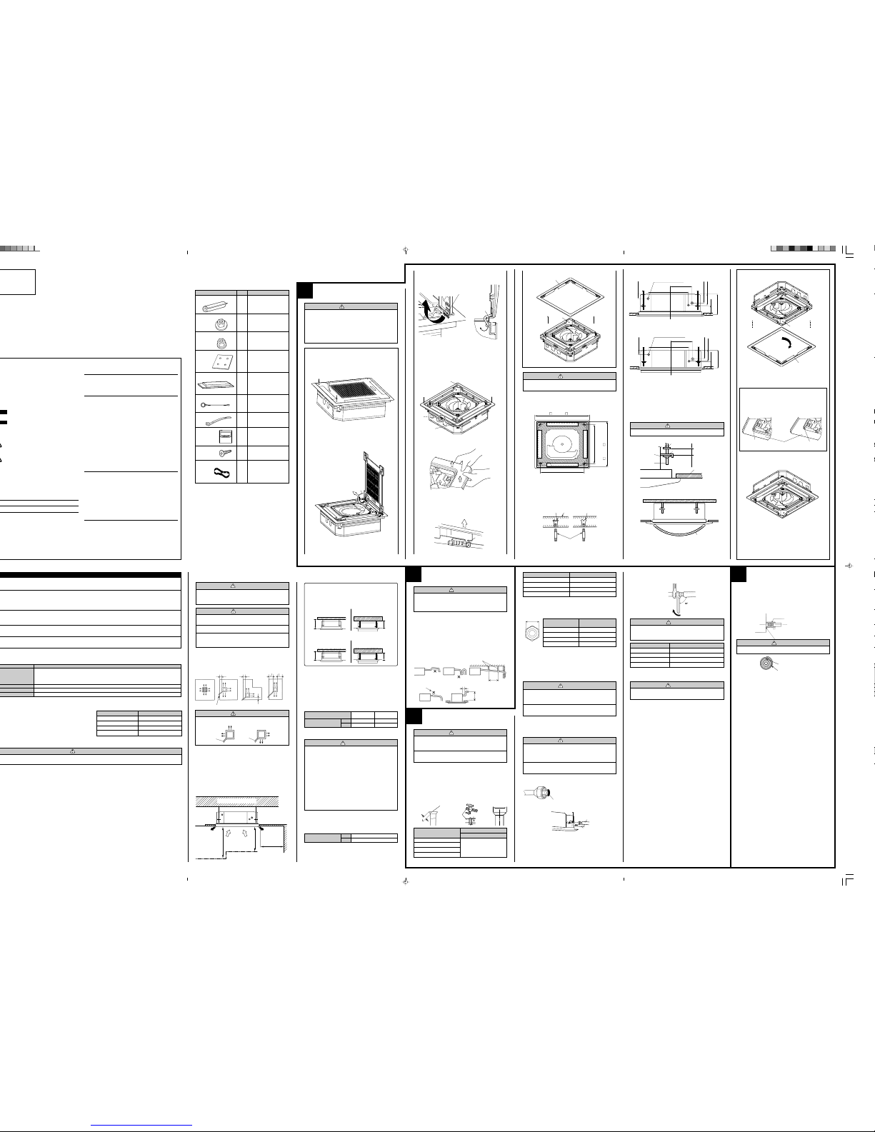
REMOVING THE INTAKE GRILLE
(1)Push the intake grille pushbuttons (two places).
(2)Open the intake grille.
OPEN
PUSH
(3)Remove the grille hinge wire.
A
• Pull up while pressing the B section.
Part A detail view Part A section view
B
(4)Remove the intake grille.
REMOVING THE PANEL FRAME
• Pull up the corner sections (A) of the panel frame as shown in
figure (4 locations).
Part A detail view
Grille hinge wire
A
A
A
A
B
• Pull up in the direction of the arrow while holding down the C
section of figure (4 locations).
Part B detail view
Panel base
C
Panel frame
CAUTION
Always remove the panel frame after removing the intake
grille.
1. POSITION THE CEILING HOLE AND HANGING
BOLTS
940 mm ( 37")
890 mm ( 35-3/64")
750 mm (29-17/32")
750 mm (29-17/32")
Hanging bolt M10
(A) Standard setting
Hole-in anchor
Hole-in plug
Concrete Insert
Drain pipe (I.D. 32 mm)
60 mm
(2-3/8")
305.5 mm (12")
298.5 mm (11-3/4")
(2-3/4")
248.5 mm
(9-25/32")
70 mm
(3-15/16")
(5")
100 mm
127 mm
235 mm (9-1/4") [18 to 24 type]
285 mm (11-7/32") [30 to 54 type]
(B) Slender setting
Drain pipe (I.D. 32 mm)
60 mm
(2-3/8")
305.5 mm (12")
298.5 mm (11-3/4")
248.5 mm
(9-25/32")
70 mm
(2-3/4")
(3-15/16")
(3-5/8")
100 mm
92 mm
200 mm (7-7/8") [18 to 24 type]
250 mm (9-27/32") [30 to 54 type]
3. BODY INSTALLATION
As for the dimension of the ceiling rear hight is above figure or more.
(1) Install special nut A, then special nut B onto the hanging bolt.
(2) Raise the body and mount its hooks onto the hanging bolt between
the special nuts.
(3) Turn special nut B to adjust the height of the body.
(4) Leveling
Using a level, or vinyl hose filled with water, fine adjust so that the
body is level.
WARNING
Perform final tightening by tightening the double nut firmly.
*Must fit tightly against ceiling
without any gap.
Special nut B
Hanging bolt
Special nut A
30 mm (1-3/16")
or more
Hook
Ceiling
After installing the body,
tighten the nuts.
* Allowable space between the unit and the ceiling 5 mm (3/16") or less
INSTALLING THE PANEL FRAME
Vinyl hose
* With slender setting, turn the panel frame 90° as shown in the dia-
gram above.
Grille setting method has been changed at the marked positions on the panel frame and panel base.
(A) Standard setting (B) Slender setting
(Example)
Panel base
Panel frame
*90° Turn
Mark
Panel frame
No mark
2. HANGING PREPARATIONS
• Firmly fasten the hanging bolts as shown in figure or by another method.
• Install the hanging bolts at a place where they would be capable of
holding a weight of at least 50 kgf per bolt.
2
INSTALLING DRAIN PIPE
CAUTION
Install the drain pipe in accordance with the instructions
in this installation instruction sheet and keep the area warm
enough to prevent condensation. Problems with the piping may lead to water leaks.
NOTE: Install the drain pipe.
••
••
• Install the drain pipe with downward gradient (1/50 to 1/100) and so
there are no rises or traps in the pipe.
••
••
• Use general hard polyvinyl chloride pipe (VP25) [outside diameter
32 mm (1-1/4")] and connect it with adhesive (polyvinyl chloride) so
that there is no leakage.
••
••
• When the pipe is long, install supporters.
••
••
• Do not perform air bleeding.
••
••
• Always heat insulate the indoor side of the drain pipe.
••
••
• When desiring a high drain pipe height, rise it up to 800 mm (31") or
less from the ceiling within a range of 150 mm (6") from the body. A
rise dimension over this range will cause leakage.
Max. 800 mm (31")
Rise
Trap
Supporter
1.5 to 2.0 m (5 to 6.5 ft)
Air bleeding
150 mm (6") or less
3
CONNECTING THE PIPING
CAUTION
1 Do not use mineral oil on flared part.
Prevent mineral oil from getting into the system as this
would reduce the lifetime of the units.
2 While welding the pipes, be sure to blow dry nitrogen
gas through them.
Do not remove the cap from the connection pipe before connecting
the pipe.
CAUTION
Be sure to connect the large pipe after connecting the small
pipe completely.
(Hanging bolt position)
(Grille measurement)
(Hanging bolt position)
(Ceiling opening measurement)
SELECTING THE MOUNTING POSITION
4
Body
Be sure to overlap the
insulation
Coupler heat insulation
No gap
Coupler heat insulation
INSTALLING THE COUPLER
HEAT INSULATION
After checking for gas leaks, insulate by wrapping insulation around the
two parts (large and small) of the indoor unit coupling, using the coupler
heat insulation.
After installing the coupler heat insulation, wrap both ends with vinyl tape
so that there is no gap.
CAUTION
Must fit tightly against body without any gap.
WARNING
Install at a place that can withstand the weight of the indoor and outdoor units and install positively so that the
units will not topple or fall.
CAUTION
1 Do not install where there is the danger of combustible
gas leakage.
2 Do not install near heat sources.
3 If children under 10 years old may approach the unit,
take preventive measures so that they cannot reach
the unit.
(B) Slender setting(A) Standard setting
215 mm (8-15/32")
or more
250 mm (9-27/32")
or more
This mechanism enables the cassette body to move 35 mm (1-3/8")
downward and realizes installation to the space of 215 or 265 mm
(8-15/32" or 10-15/32"). No special works and option is needed.
You can select 2-way setting
[18 to 24 type]
(B) Slender setting(A) Standard setting
265 mm (10-15/32")
or more
300 mm (11-13/16")
or more
[30 to 54 type]
CONNECTION PIPE REQUIREMENT
CAUTION
Install heat insulation around both the gas and liquid pipes.
Failure to do so may cause water leaks.
Use heat insulation with heat resistance above 248 °F. (Reverse cycle model only)
In addition, if the humidity level at the installation location
of the refrigerant piping is expected to exceed 70%, install
heat insulation around the refrigerant piping. If the expected humidity level is 70-80%, use heat insulation that
is 15 mm (19/32") or thicker and if the expected humidity
exceeds 80%, use heat insulation that is 20 mm (3/4") or
thicker.
If heat insulation is used that is not as thick as specified,
condensation may form on the surface of the insulation.
In addition, use heat insulation with heat conductivity of
0.045 W/(m·K) or less (at 68 °F).
ELECTRICAL REQUIREMENT
••
••
• Install all electrical works in accordance to the standard.
••
••
• Install the disconnect device with a contact gap of at least 3 mm (1/8")
in all poles nearby the units. (Both indoor unit and outdoor unit)
••
••
• Install the circuit breaker nearby the units.
••
••
• Use pipe with water-resistant heat insulation.
Connection cord (mm2)
MAX.
MIN.
2.5
1.5
••
••
• Electric wire size:
This symbol refers to a hazard or unsafe practice which
can result in severe personal injury or death.
This symbol refers to a hazard or unsafe practice which
can result in personal injury and the potential for
product or property damage.
Electrical
Safety / alert
When Transporting
Be careful when picking up and moving the indoor and outdoor units. Get
a partner to help, and bend your knees when lifting to reduce strain on
your back. Sharp edges or thin aluminum fins on the air conditioner can
cut your fingers.
When Installing...
...In a Ceiling or Wall
Make sure the ceiling/wall is strong enough to hold the unit’s weight. It
may be necessary to construct a strong wood or metal frame to provide
added support.
...In a Room
Properly insulate any tubing run inside a room to prevent “sweating” that
can cause dripping and water damage to walls and floors.
...In Moist or Uneven Locations
Use a raised concrete pad or concrete blocks to provide a solid, level
foundation for the outdoor unit. This prevents water damage and abnormal vibration.
...In an Area with High Winds
Securely anchor the outdoor unit down with bolts and a metal frame.
Provide a suitable air baffle.
...In a Snowy Area (for Heat Pump-type Systems)
Install the outdoor unit on a raised platform that is higher than drifting
snow. Provide snow vents.
When Connecting Refrigerant Tubing
•
Keep all tubing runs as short as possible.
•
Use the flare method for connecting tubing.
•
Apply refrigerant lubricant to the matching surfaces of the flare and
union tubes before connecting them, then tighten the nut with a torque
wrench for a leak-free connection.
•
Check carefully for leaks before starting the test run.
NOTE:
Depending on the system type, liquid and gas lines may be either narrow
or wide. Therefore, to avoid confusion the refrigerant tubing for your
particular model is specified as either “small” or “large” rather than as
“liquid” or “gas”.
When Servicing
•
Turn the power OFF at the main circuit breaker panel before opening
the unit to check or repair electrical parts and wiring.
•
Keep your fingers and clothing away from any moving parts.
•
Clean up the site after you finish, remembering to check that no metal
scraps or bits of wiring have been left inside the unit being serviced.
•
After installation, explain correct operation to the customer, using the
operating manual.
This air conditioner uses new refrigerant HFC (R410A).
Contents of change
Pressure is high and cannot be measured with a conventional gauge. To prevent erroneous mixing of other
refrigerants, the diameter of each port has been changed.
It is recommended the gauge with seals –0.1 to 5.3 MPa (–76 cmHg to 53 kgf/cm
2
) for high pressure.
–0.1 to 3.8 MPa (–76 cmHg to 38 kgf/cm
2
) for low pressure.
To increase pressure resistance, the hose material and base size were changed.
A conventional vacuum pump can be used by installing a vacuum pump adapter.
Special gas leakage detector for HFC refrigerant R410A.
Tool name
6.35 mm (1/4 in.)
9.52 mm (3/8 in.)
12.70 mm (1/2 in.)
15.88 mm (5/8 in.)
0.80 mm (0.0315 in.)
0.80 mm (0.0315 in.)
0.80 mm (0.0315 in.)
1.00 mm (0.0394 in.)
Pipe outside diameter
Thickness
Thicknesses of Annealed Copper Pipes (R410A)
CAUTION
GENERAL
This INSTALLATION INSTRUCTION SHEET briefly outlines where and
how to install the air conditioning system. Please read over the entire set
of instructions for the indoor and outdoor units and make sure all accessory parts listed are with the system before beginning.
* Appearance of slender setting
1. FLARING
(1) Cut the connection pipe to the necessary length with a pipe cutter.
(2) Hold the pipe downward so that cuttings will not enter the pipe and
remove the burrs.
(3) Insert the flare nut (always use the flare nut attached to the indoor
and outdoor units respectively) onto the pipe and perform the flare
processing with a flare tool.
Use the special R410A flare tool, or the conventional flare tool.
Check if [L] is flared uniformly
and is not cracked or scratched.
B
Die
A
Pipe
6.35 mm (1/4 in.)
9.52 mm (3/8 in.)
12.70 mm (1/2 in.)
15.88 mm (5/8 in.)
0 to 0.5 mm
(0 to 0.0197 in.)
Pipe outside diameter
Dimension A
Flare tool for R410A, clutch type
Width across flats
6.35 mm (1/4 in.)
9.52 mm (3/8 in.)
12.70 mm (1/2 in.)
15.88 mm (5/8 in.)
9.1 mm (0.3583 in.)
13.2 mm (0.5197 in.)
16.6 mm (0.6536 in.)
19.7 mm (0.7756 in.)
Pipe outside diameter
Dimension B
When using conventional flare tools to flare R410A pipes, the dimension
A should be approximately 0.5 mm (1/32") more than indicated in the
table (for flaring with R410A flare tools) to achieve the specified flaring.
Use a thickness gauge to measure the dimension A.
Pipe outside
diameter
Width across flats
of Flare nut
6.35 mm (1/4 in.)
9.52 mm (3/8 in.)
12.70 mm (1/2 in.)
15.88 mm (5/8 in.)
17 mm (0.6693 in.)
22 mm (0.8661 in.)
26 mm (1.0236 in.)
29 mm (1.1417 in.)
CAUTION
1 To prevent breaking of the pipe, avoid sharp bends.
Bend the pipe with a radius of curvature of 150 mm (6")
or over.
2 If the pipe is bent repeatedly at the same place, it will
break.
The pipes are shaped by your hands. Be careful not to collapse them.
Do not bend the pipes in an angle more than 90
°.
When pipes are repeatedly bend or stretched, the material will harden,
making it difficult to bend or stretch them any more. Do not bend or
stretch the pipes more than three times.
2. BENDING PIPES
To prevent gas leakage, coat the flare
surface with alkylbenzene oil (HAB).
Do not use mineral oil.
(3) When the flare nut is tightened properly by your hand, use a torque
wrench to finally tighten it.
Holding spanner
Body side
Indoor unit
Connection pipe
(Liquid)
Connection pipe
(Gas)
(2) Centering the pipe against port on the indoor unit, turn the flare nut
with your hand.
3. CONNECTION PIPES
Indoor unit
(1) Detach the caps and plugs from the pipes.
CAUTION
1 Be sure to apply the pipe against the port on the in-
door unit correctly. If the centering is improper, the flare
nut cannot be tightened smoothly. If the flare nut is
forced to turn, the threads will be damaged.
2
Do not remove the flare nut from the indoor unit pipe
until immediately before connecting the connection pipe.
Torque wrench
CAUTION
Hold the torque wrench at its grip, keeping it in the right
angle with the pipe, in order to tighten the flare nut
correctly.
Flare nut Tightening torque
6.35 mm (1/4 in.) dia.
9.52 mm (3/8 in.) dia.
12.70 mm (1/2 in.) dia.
15.88 mm (5/8 in.) dia.
16 to 18 N·m (160 to 180 kgf·cm)
30 to 42 N·m (300 to 420 kgf·cm)
49 to 61 N·m (490 to 610 kgf·cm)
63 to 75 N·m (630 to 750 kgf·cm)
14000, 18000 BTU/h 24000, 36000,
model 42000 BTU/h model
MODEL
Diameter
Liquid
Gas
6.35 mm (1/4 in.) 9.52 mm (3/8 in.)
12.70 mm (1/2 in.)15.88 mm (5/8 in.)
Page 2
Red
White
Black
G
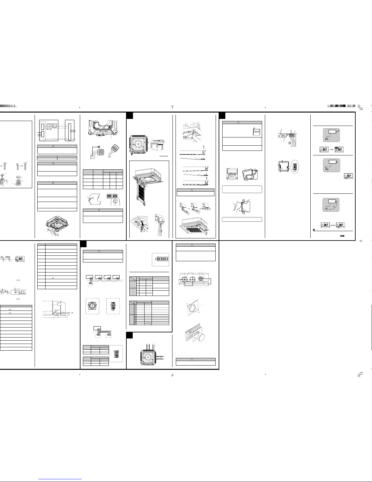
GRILLE INSTALLATION
BLOWER COVER INSULATION
Install the blower cover insulation only when the outlet direction is not
specified.
Two blower cover insulations are packed with the indoor unit.
Install the blower cover insulation at the diffuser position shown in figure.
At this time, use the piping position as the criteria.
A-A Section view
A
A
INSTALLING THE INTAKE GRILLE
(1)Mount the grille hinge wire to the hook shaft as shown in figure.
A
• Latch the grille hinge wire to the hook shaft, and fasten.
Part A detail view Part A section view
Grille hinge
wire
(2)Install the hook wire.
• Pass the hook wire through the panel base from the rear side as
shown in figure, and fasten to the reinforced metal fitting of the
intake grille using a screw.
Screw
Section view
2 direction example
(Piping direction)
Blower cover
insulation
Panel
base
Drain
pan
Hook shaft
Hook wire
RFM (grille)
(3)Loosen the screw, put the loop of the hook wire over it, and tighten
the screw again.
CAUTION
Install the intake grille hook wire to the grille assembly. If it falls, it may cause injuries.
(4)Bring up the intake grille by pushing it up at an angle as shown in
figures, and fasten.
Hook wire
(1) Remove the control box cover and terminal box cover and install the
connection cord and remote controller cord.
Remote controller cord
Terminal board
(Indoor unit)
Ceiling height
Normal
High ceiling 1
High ceiling 2
Low ceiling
1
–
–
–
–
2.5 - 3.0 m
(8.2-9.8 ft)
3.0 - 3.5 m
(9.8-11.5 ft)
More than 3.5 m
(More than 11.5 ft)
Less than 2.5 m
(Less than 8.2 ft)
2
OFF
ON
OFF
ON
3
OFF
OFF
ON
ON
DIP-SW4
ELECTRICAL WIRING
Loop
B. Strand wire
Strip 10 mm (3/8")
Round
terminal
Screw with
special washer
Round terminal
Terminal
board
Wire
Screw with
special washer
Round
terminal
2. INDOOR UNIT SIDE
WARNING
1 Before starting work, check that power is not being sup-
plied to the indoor unit and outdoor unit.
2 Match the terminal board numbers and connection cord
colors with those of the outdoor unit.
Erroneous wiring may cause burning of the electric
parts.
3 Connect the connection cord firmly to the terminal
board. Imperfect installation may cause a fire.
4 Always fasten the outside covering of the connection
cord with the cord clamp. (If the insulator is chafed,
electric leakage may occur.)
5 Always connect the ground wire.
(2) After wiring is complete, clamp the remote controller cord and con-
nection cord with the cord clamp.
Terminal box cover
Control box cover
Cord clamp
Connection cord
(To the outdoor unit)
Ceiling height setting
Set the DIP switch for the ceiling height according to the table below.
Remote
controller
Terminal board
OUTDOOR
UNIT
Connection
cord
6
1. INSTALLING THE REMOTE CONTROLLER
(1) Open the operation panel on the front of the remote controller, remove
the two screws indicated in the following figure, and then remove the
front case of the remote controller.
Front case
(back side)
Rear case
Connector
Remote
controller wires
Rear case
Connector
Front case
1. Red
2. White
3. Black
Binder
3. SETTING THE DIP SWITCHES
When using a battery (memory backup)
Change the DIP switch setting to use batteries. (The DIP switch is not set
to use batteries at the factory.)
Change DIP switch 1 No. 6 from OFF to ON.
If batteries are not used, all of the settings stored in memory will be deleted if there is a power failure.
Screws
2. ROUTING THE REMOTE CONTROLLER WIRES
(1) Install the remote controller wires to the terminals on the top of the
rear case as shown in the following figure.
(2) Fasten the wires with the binder.
(Example)
7
REMOTE CONTROLLER
SETTING
CAUTION
1 In order to detect the room temperature
correctly when using the temperature
sensor of the remote controller, do not
install the remote controller in a place
where it will be exposed to direct sunlight or directly below the air outlet of
the indoor unit.
2 When installing the remote controller and cord near a
source of electromagnetic waves, separate the remote
controller from the source of the electromagnetic waves
and use shielded cord.
3 Do not touch the remote controller PC board and PC
board parts directly with your hands.
Temperature sensor
When installing the remote controller, remove the connector from the
front case. The wires may break if the connector is not removed and
the front case hangs down.
When installing the front case, connect the connector to the front case.
(2) Install the rear case to the wall, etc. with the two tapping screws.
Refer to the following information to install the remote controller wires.
SUMOTUWETH FR
SA
4. SETTING THE ROOM TEMPERATURE DETECTION LOCATION
The detection location of the room temperature can be selected from the
following three examples. Choose the detection location that is best for
the installation location.
A. Indoor unit setting (factory setting)
The room temperature is detected by the indoor unit temperature sensor.
A
B. Remote controller setting
The room temperature is detected by the remote controller temperature
sensor.
B
C
Indoor unit
When the THERMO SENSOR button is pressed, the lock display flashes
because the function is locked at the factory.
(1) Press the THERMO SENSOR button for 5
seconds or more to unlock the function. The
thermo sensor display flashes and then disappears when the function is unlocked.
(2) Press the THERMO SENSOR button. The thermo sensor display ap-
pears.
(3) Press the THERMO SENSOR button again for 5 seconds or more to
lock the function. The thermo sensor display flashes and then remains
on when the function is locked.
(4) Make sure that the function is locked.
C.Indoor unit/remote controller setting
(room temperature sensor selection)
The temperature sensor of the indoor unit or the remote controller can be
used to detect the room temperature.
TEST RUN
Unit number (usually 0)
Error code
simultaneously for
Test run display
Ex. Self-diagnosis
Indoor unit No. 0 Indoor unit No. 1Indoor unit No. 2 Indoor unit No. 3
Remote
controller
wire
Remote
controller
(2) Rotary switch setting (indoor unit)
Set the unit number of each indoor unit using the rotary switch on the
indoor unit circuit board.
The rotary switch is normally set to 0.
(3) DIP switch setting (remote controller)
Change DIP switch 1 No. 3 on the remote controller from OFF to ON.
Indoor unit
Rotary Switch
Remote controller
DIP Switch 1
2. DUAL REMOTE CONTROLLERS (OPTIONAL)
Two separate remote controllers can be used to operate the indoor units.
(1) Wiring method (indoor unit to remote controller)
(2) DIP switch setting (remote controller)
Set the remote controller DIP switch 1 No. 1 and 2 according to the
following table.
Number of
remote
controllers
Master unit
1 (Normal)
2 (Dual)ONOFF
OFF
OFF
DIP-SW 1 No. 1
DIP-SW 1 No. 2
Remote controller
DIP Switch 1
Number of
remote
controllers
Slave unit
1 (Normal)
2 (Dual)–ON–ON
DIP-SW 1 No. 1
DIP-SW 1 No. 2
SW3
1 2 3
1 2 3
1 2 3
ONOFF
1
2
3
4
5
6
ON
1 2 3 1 2 3 1 2 3
1 2 3
1 2 3
ONOFF
1
2
3
4
5
6
NO.
SW state
Detail
OFF ON
1 Invalidity Validity
★
Auto restart setting
2— —
★
Temperature correction
3— —
★
setting
1—
★
— Remote controller setting
2—
★
—
Air flow setting
3—
★
—
DIP-Switch 1
● Indoor unit
● Remote controller
[DIP-SWITCH SETTING]
DIP-Switch 4
OPENING THE DUCT
CONNECTION HOLE
Distribution duct
Distribution duct
Fresh air
CAUTION
1 When performing hole opening work, be careful not to
damage the drain pan.
2 When connecting the distribution duct, to make the air
flow easily, block the outlet port with the blower cover
insulation as shown by the hatched lines in the figure.
For the blocking direction, refer to blower cover insulation figure.
1. DIMENSION
Screw position and connection hole which are fresh air duct and distribution duct.
45°
45°
ø100
ø70
12-ø3.3 self tapping screw holes (for 4 mm)
2. DISTRIBUTION DUCT AND FRESH AIR DUCT
HOLE PROCESSING
Use the distribution duct hole and fresh air duct hole by removing the
insulation material as shown below.
Cut
Cut
Cabinet
• Cut off the part (Cabinet) indicated by the arrow in the figure with
nippers, needle nose pliers, etc.
PART NO. 9370937022
NOTES
If the function to change the temperature sensor is used as shown in
examples A and B (other than example C), be sure to lock the detection
location. If the function is locked, the lock display
will flash when
the THERMO SENSOR button is pressed.
(1) Press the THERMO SENSOR button for 5 seconds or more to unlock
the function. The thermo sensor display flashes and then disappears
when the function is unlocked.
(2) Press the THERMO SENSOR button to select the temperature sen-
sor of the indoor unit or the remote controller.
1. GROUP CONTROL SYSTEM
A number of indoor units can be operated at the same time using a single
remote controller.
(1) Wiring method (indoor unit to remote controller)
Cabinet
Knife
Insulation
(Inner box)
10
123
O
F
F
SW 4
123
O
F
F
SW 1
Indoor unit PC board
Dip switch
(SW4)
Indoor unit
PC board
DAY OFF
DELETE SET
ENERGY
SAVE
THERMO
SENSOR
SET BACK
DAY
CLOCK ADJUST
3. AUTO RESTART
• When the air conditioner power was temporarily turned off by a power
failure etc., it restarts automatically after the power recovers.
(Operated by setting before the power failure)
The auto restart function can be
canceled.
(1) DIP switch setting (indoor unit)
Change the DIP switch (SW1-1)
on the indoor unit circuit board
from ON to OFF. The auto restart
function will be canceled.
Indoor unit
OFF
123
OFF
SW1
OFF
123
SW4
DIP Switch
2. CHECKING DRAINAGE
To check the drain, remove the water cover and fill with 2 to 3rof water as
shown in figure.
The drain pump operates when operating in the cooling mode.
Water cover
Drain pipe
Watering pot
9
SPECIAL INSTALLATION
METHODS
CAUTION
1 When setting the rotary switch and DIP switches, do
not touch any other parts on the circuit board directly
with your bare hands.
2 Be sure to turn off the main power.
Indoor unit
Indoor unit
Remote
controller
wire
Indoor unit
Master
unit
Slave
unit
• Open the holes and cut the insulation with a knife.
* Be careful not to damage the internal parts.
* Be careful not to cut yourself on the cutout in the metal plate.
* Please remove the insulation (inner box) left over after cutting.
• Connect the distribution duct.
* When mounting the duct, block the gap so that there is no cold air leakage.
*Insulate the duct and cut connection.
CAUTION
The air conditioner cannot take in fresh air by itself. When
connecting a fresh air duct, always use a duct fan.
Remote
controller
1. WIRING SYSTEM DIAGRAM
Communication error
(indoor unit
remote controller)
Communication error
(indoor unit outdoor unit)
Room temperature sensor open
Room temperature sensor short-circuited
Indoor heat exchanger temperature sensor open
Indoor heat exchanger temperature sensor shortcircuited
Outdoor heat exchanger temperature sensor
Power source connection error
Float switch operated
Outdoor temperature sensor
Discharge pipe temperature sensor
Model abnormal
Indoor fan abnormal
Error code Error contents
Outdoor signal abnormal
Excessive outdoor pressure (permanent stop)
Compressor temperature sensor
Pressure switch error
IPM error
CT error
Active filter module (AFM) error
Compressor does not operate
Outdoor unit fan error
Communication error
(inverter multicontroller)
2 way valve sensor error
Expansion valve error
Connection indoor unit error
13
14
15
16
17
18
19
1A
1b
1c
1d
1E
1F
CAUTION
1 If the setting for a low ceiling is selected, the capacity
of the air conditioner decreases slightly.
2 Do not set any switches other than those specified in
this sheet. The air conditioner may not operate correctly
if any switches other than those specified are changed.
Install the remote controller wire so as not to be direct touched with
your hand.
DIP switch 1
Front case (back side)
ONONOFF
1
2
3
4
5
6
DIP switch 2
Jumper
P. D 120 P. D 88
97 mm
160 mm (6-5/16")
334.2 mm (13-5/32")
113 mm
(4-7/16")
(★: Factory setting)
ON
★
Multiple units
Cooling only model
★ Validity
Validity
Invalidity
Invalidity
★ Invalidity
Invalidity
Detail
Dual remote controller setting
Group control setting
Model setting
AUTO changeover setting
Memory Backup setting
THERMO SENSOR button setting
ENERGY SAVE button setting
Horizontal airflow direction and swing button setting
Vertical airflow direction and swing button setting
Cannot be used.
Cannot be used.
No.
1
2
3
4
5
6
1
2
3
4
5
6
OFF
★
★ One unit
★
Heat & cool model
Invalidity
★ Invalidity
★ Validity
★ Validity
Validity
★ Validity
★ Fixed at OFF
★ Fixed at OFF
SW state
DIP-
switch 1
DIP-
switch 2
CAUTION
1 Be sure to refer the above diagram and do correct field
wiring.
Wrong wiring causes malfunction of the unit.
2 Check local electrical codes and also any specific
wiring instructions or limitation.
1
2
3
L
N
1
2
3
GG
1
2
3
INDOOR
INDOOR UNIT
OUTDOOR UNIT
TERMINAL
DISCONNECT
SWITCH
(FIELD
SUPPLY)
Grounding
line
14AWG
(Inter-unit)
Power lines
230/208 V
230/208 V
230/208 V
TERMINAL
Power supply line
Single-phase, 230/208 V
WARNING
Disconnect switch and circuit breaker for over current protection given in the table below is to be installed between
the indoor unit and the outdoor unit.
15A 240 V - 5A
Disconnect switch
Circuit breaker (or Fuse)
CIRCUIT
BREAKER
OR FUSE
(FIELD
SUPPLY)
Remote controller line
 Loading...