

Page 1

Operating Manual
System
FUJITSU Desktop
ESPRIMO Q55x / Q95x
Page 2

Thank you for buying an inno
vative product from Fujitsu.
Latest information abo
on our website: "
You c a n find driver upda
Should you have any te
• our Hotline/Service
• Your sales partner
• Your sales office
We hope you enjoy using your new Fujitsu system!
ut our products, useful tips, updates etc. is available
//www.fujitsu.com/fts/"
http:
tes at: "
http://support.ts.fujitsu.com/download"
chnical questions, please contact:
Desk ("
http://support.ts.fujitsu.com/contact/serv icedesk")
Page 3

Page 4

Published by / Contact address in the EU
chnology Solutions GmbH
Fujitsu Te
Mies-van-der-Rohe-Straße 8
80807 Munich, Germany
www.fujitsu.com/fts/"
http://
"
Copyright
u Technology Solutions GmbH 2016. All rights reserved.
©Fujits
Publication Date
11/2016
Order No.: A26361-K1012-Z320-1-7619, edition 3
Page 5

FUJITSU Desktop
ESPRIMO Q55x / Q95x
Operating Manual
Your ESPRIMO 7
Ports and operating elements 9
Important notes 13
Getting started 15
Operation 37
Troubleshooting and tips 53
System expansions 58
Technical data 89
Index 90
Page 6

Remarks
Information on the product description meets the design specifications of Fujitsu and
is provided for comparison purposes. Several factors may cause the actua l results to
differ. Technical data is subject to change without prior notification. Fujitsu rejects any
responsibility with regard to technical or editorial mistakes or omissions.
Trademarks
Fujitsu, the Fujitsu logo and ESPRIMO are registered trademarks of Fujitsu Limited
or its subsidiaries in the USA and other countries.
PS/2 is a registered trademark of International Business Machines, Inc.
Kensington is a registered trademark of the ACCO brand.
Microsoft and Windows are trademarks or registered trademarks of Microsoft
Corporation in the U S A and/or oth er countries.
All other trademarks specified here are the property of their respective owne rs.
Copyright
No part of this publication may be copied, reproduced or translated without
the prior written consent of Fujitsu.
No part of this publication may be saved or transferred by any electronic means
without the written approval of Fujitsu.
Page 7

Contents
Contents
YourESPRIMO ......................................................................... 7
Validity ofthe Reference Manual ......................................................... 7
Notational conventions .................................................................. 8
Ports and operating elemen
Front ................................................................................... 9
Rear ................................................................................... 11
Importantnotes ........................................................................ 13
Safety information ....................................................................... 13
Transportingthe device .................................................................. 13
Cleaning the device ..................................................................... 14
Energy saving, disposal andrecycling .................................................... 14
Importantnotes on ESPRIMO Q957 .................................................. 14
Getting started ......................................................................... 15
Unpacking and chec
Steps for initial
Fitting the under
Setting up the dev
Operating posit
Attaching the ad
Fitting the bas
Fitting the de
Connecting th
Connecting ex
Ports on the d
Connecting a
Connecting a
Connecting
Connecting
Connectin
Connectin
gonforthefirst time: installingthe software .......................................
Switchin
Switch on
ng thesoftware ...............................................................
Installi
Operation .............................................................................. 37
Switch thedeviceon .................................................................... 37
Switchingoff the device ................................................................. 37
Indicators on the device ................................................................. 38
Keyboard ............................................................................... 39
Important keys and keyboard shortcuts . . . . ............................................ 39
Optical drive (device dependent) . . ....................................................... 41
Handling data carriers ............................................................... 41
Insertingor removinga data carrier ................................................... 42
Manual removal of dat a carriers (emergency removal) . . . . . ............................. 43
Wireless LAN / Bluetooth wireless components (device dependent) ......................... 43
Switching the wireless components on and off . ........................................ 43
Settings in BIOSSetupUtility ............................................................ 44
Starting the BIOS Setup Utility ........................................................ 44
OperatingBIOS Setup Utility ......................................................... 45
king the delivery .....................................................
setup ....................................................................
side cover (device dependent) ............................................
ice ....................................................................
ion ...................................................................
hesive feet (optional) .................................................
e(optional) ............................................................
vice to theVESA interface on amonitor (optional) .........................
epower cable .............................................................
ternal devices .............................................................
evice ..................................................................
monitor ................................................................
USB mouse ............................................................
a USB keyboard . . .......................................................
external devices to the serial interface .....................................
gexternal devices to the USB ports .........................................
gthe PS/2 device ..........................................................
the monitor andthe machine ...............................................
ts .........................................................
15
15
16
18
18
21
22
22
30
32
32
33
33
33
33
34
34
35
35
36
9
Fujitsu 3
Page 8

Contents
Exiting BIOS Setup Utility ............................................................ 45
Property and data protection ............................................................. 46
BIOS Setup security functions ........................................................ 46
Using the SmartCard reader (device dependent) . . . . . .................................. 46
Using a palm sensor (device dependent) . ............................................. 48
Usingthe Security Lock .............................................................. 49
Usinga locking bracket .............................................................. 50
Lead-sealing the casing .............................................................. 52
Troubleshootingand tips .............................................................. 53
Help if problems occur ................................................................... 53
Troubleshooting . . ....................................................................... 53
Power-on indicator remains unlit afteryou have switchedon your device ................. 53
The device cannot be switched off with the O N/OFF switch. . . .......................... 54
Monitor remains blank ............................................................... 54
No mouse pointerdisplayed on thescreen ............................................ 55
Time and/or date is not correct . . . . . . ................................................. 55
SmartCard reader is not recognised. . ................................................. 55
SmartCard PIN forgotten ............................................................. 55
SmartCard lost ...................................................................... 56
User and/or supervisor SmartCard lost . . ............................................. 56
Errormessages onthe screen ........................................................ 56
Installing newsoftware .................................................................. 56
Restoringthe hard disk contents ......................................................... 56
Tips .................................................................................... 57
System expansions .................................................................... 58
Information about boards ................................................................ 59
Overview of thedrive bays and drives in your device ....................................... 60
Prepare to remove compone nts . . ........................................................ 62
Removing and attaching the topcasingcover ............................................. 63
Removing the topcasing cover ....................................................... 63
Securing the top casing cover ........................................................ 64
Insertingand removing thedrive cage .................................................... 65
Removing the drive cage ............................................................ 65
Installing thedrive cage .............................................................. 66
Installing and removing an optical drive (device dependent) . . .............................. 66
Installing theoptical drive ............................................................ 66
Removing the opticaldrive ........................................................... 70
Installing and removing the SmartCard reader and palm sensor (device dependent) . . . . . . .... 73
Installing the SmartCard reader/palm sensor . . ......................................... 73
Removing the SmartCard reader/palm sensor ......................................... 75
Removing and installing the 2.5" hard disk ................................................ 77
Removing the 2.5" hard disk ......................................................... 77
Installing a2.5"hard disk ............................................................ 78
Removing and installing the fan .......................................................... 80
Removing the fan ................................................................... 80
Installing thefan .................................................................... 81
Inserting and removing the M.2 module . . ................................................. 82
Removing the M.2module ........................................................... 82
Installing theM.2 module ............................................................ 83
Replacingthe lithiumbattery ............................................................. 84
Removing and attaching the topcasingcover ............................................. 85
Removing the bottom casing cover ................................................... 85
4 Fujitsu
Page 9

Contents
Securing the bottom casingcover ..................................................... 86
Installing and removing memory expansion . . . . ............................................ 86
Open the service cover .............................................................. 87
Removing memorymodules .......................................................... 87
Installing amemory module .......................................................... 88
Closethe servicecover .............................................................. 88
Finish component removal . . . . ........................................................... 88
Technical data ......................................................................... 89
Index .................................................................................. 90
Fujitsu 5
Page 10

Contents
6 Fujitsu
Page 11

Your ESPRIMO
Your ESPRIMO
Overview
... is available with various configuration levels which differ in terms of hardware and software
equipment. You can install additional drives (for exam ple a D VD drive) and other boa rds.
This manual tells you how to start using your device and how to operate it in da ily use.
This manual applies for all configuration levels. Depending on the chosen configuration
level, some of the hardware components d escribed may not be available o n y our PC.
Please also read the notes about your operating system.
Depending on the configuration selected, the operating s ystem is preinstalled
on your hard disk (e.g. Windows).
Further information on this device is provided:
• in the "Q uick Start Guide" poster
• in the "Safety/regul
• in the "Warranty" manual
• in the "BIOS Setup"
• in the operating manual for the monitor
• in the manual for t
• in your operating system documentation
• in the informati
ValidityoftheReferenceManual
This Reference Manual is valid for the following systems:
• FUJITSU Desktop ESPRIMO Q556 (if applicable, followed by suffixes)
• FUJITSU Des
• FUJITSU Desktop ESPRIMO Q957
ations" manual
manual
he mainboard
on files (e.g. *.PDF, *.HTML, *.DOC, *.CHM, *.TXT, *.HLP)
ktop ESPRIMO Q956
Fujitsu 7
Page 12
Your ESPRIMO
Notational conventions
Pay particular atten tion to text marked with this symbol. Failure to observe
these warnings could pose a risk to health, damage the device or lead
to loss of data. The w arranty will be invalidated if the device becomes
defective through failure to observe these warnings.
Indicates important informa
tion for the proper use of the device.
►
This font
This font
This fo n t
"This font"
Key
This font
Indicates an activity that must be performed
Indicates a result
indicates data entered
the command line, e.g.
start a program (star
indicates information that is displayed on the screen by a program, e.g.:
Installation is complete.
indicates
• terms and texts used in a software interface, e.g.: Click on Save
• names of programs or files, e.g. Windows or setup.exe.
indicates
• cross-references to another section, e.g. "Safety information"
• cross-references to an external source, e.g. a web address: For more
information, go to "
• Names of CDs, DVDs and titles or designations for other materials,
e.g.: "CD/DVD Drivers & Utilities" or "Safety/Regulations" manual
indicates a key on the keyboard, e.g:
indicates terms and texts that are emphasised or highlighted, e.g.: Do
not switch off the device
using the keyboard in a program dialogue or at
your password (Name123) or a command used to
t.exe)
http://www.fujitsu.com/fts"
F10
8 Fujitsu
Page 13
Ports and operating elements
Ports and operating elements
Ports
This chapter presents the individual hardware c ompon ents of your device. This will provide
you with an overview of the p orts and operating elements on the device. Please familiarise
yourself with these components before starting to work with your device.
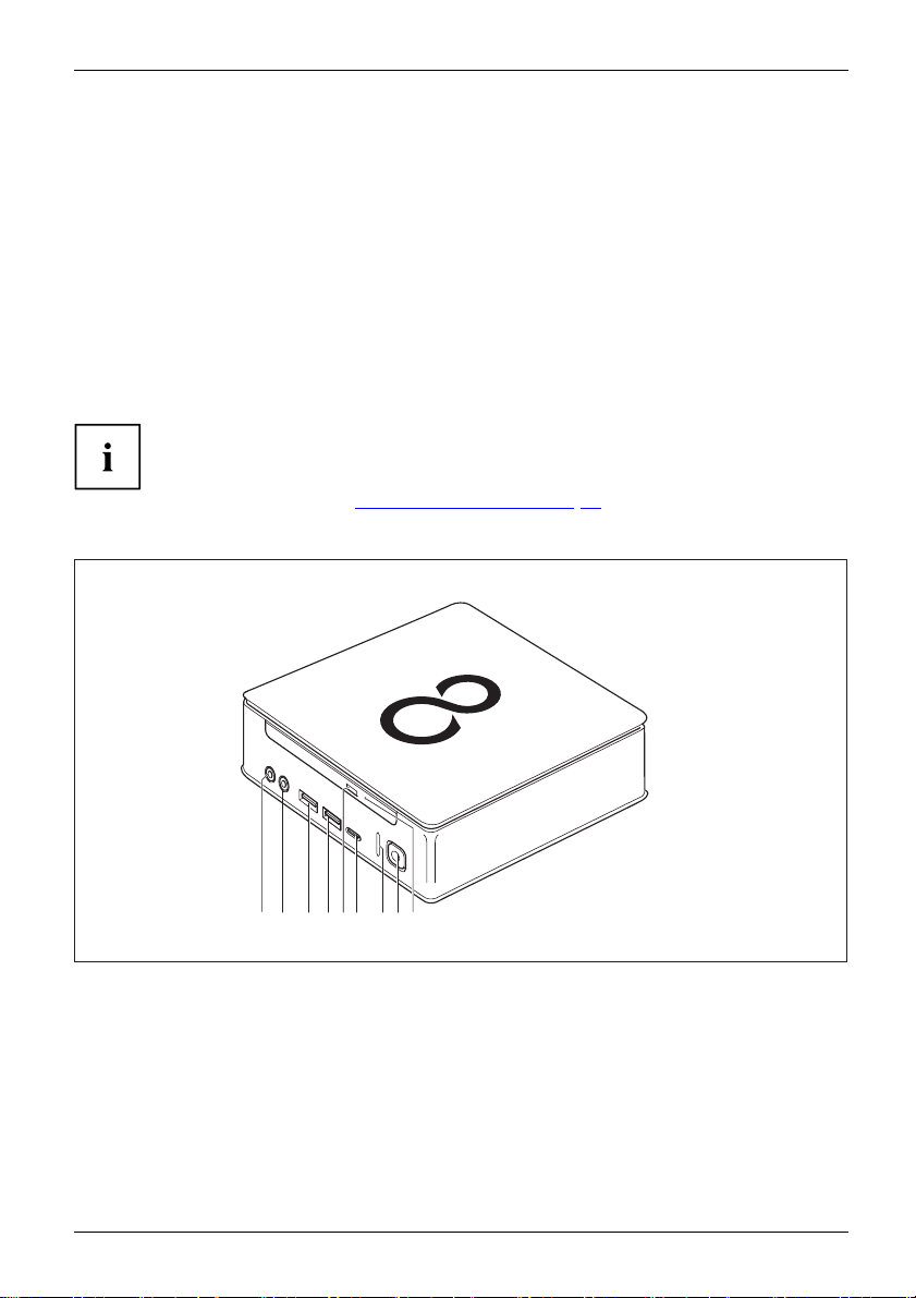
Front
The device is available i
• Device variant with opt
• Device variant with SmartCard reader and/or palm sensor
If you have not installed either an optical drive or a SmartC ard reader
/ palm sensor, fit the blanking plate.
You c a n find information on modifying the device and on installing and removing
components in Section "
Device variant with the maximum of comp onents
n several device variants:
ical drive
System expansions", Page 58.
12 34 76 8
1 = Microphone port
2 = Audio output
3 = USB port (USB 3.1, type A)
4 = USB port (USB 3.1, type A)
5 = Insert/eject button, optical drive (optional)
Fujitsu 9
5
9
6 = USB port (USB 3.1, type C )
7 = Hard disk indicator
8 = ON/OFF switch with power indicator
9 = Emergency removal
Page 14
Ports and operating elements
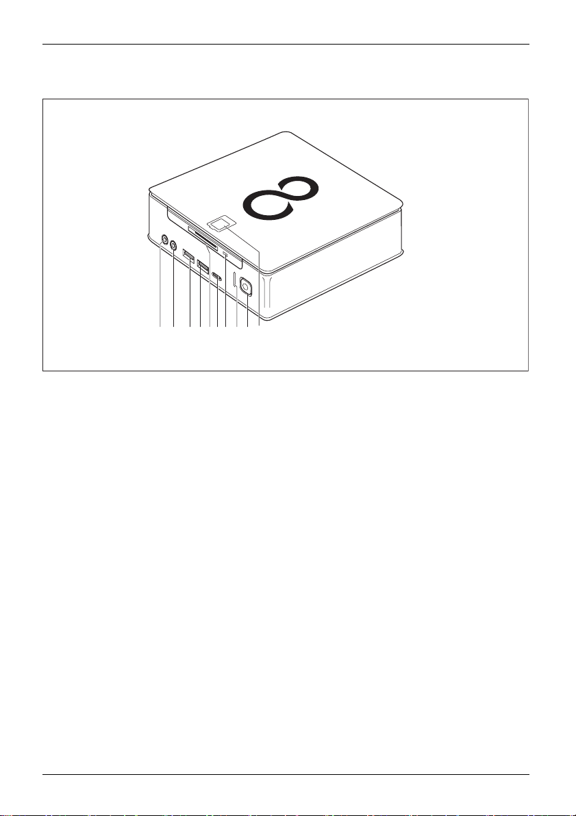
Device variant with SmartCard reader and/or palm sensor
8 91 2 3 4 5 76 10
1 = Microphone port
2 = Audio output
3 = USB port (USB 3.1, type A)
4 = USB port (USB 3.1, type A)
5 = SmartCard reader (optional)
10 Fujitsu
6 = USB port (USB 3.1, t ype C)
7 = SmartCard reader indicator (optional)
8 = Hard disk indicator
9 = ON/OFF switch with power-on indicator
10 = Palm sensor (optional)
Page 15
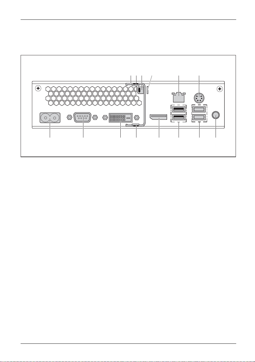
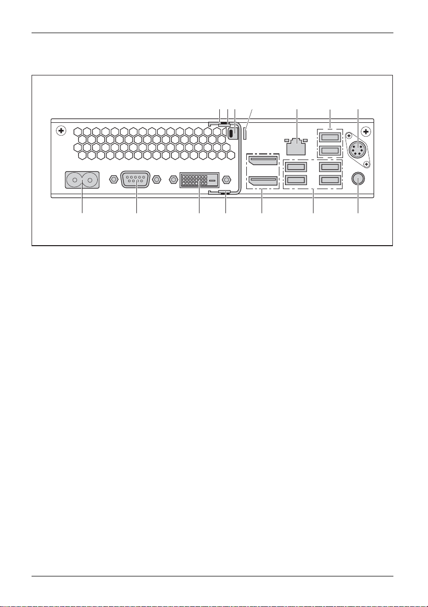
Rear
FUJITSU Desktop ESPRIMO Q55x
Ports and operating elements
14 13 12 10 9
1 = Locking bracket (optional)
2 = Top casing cover unlocking mechanism
3 = Security lock device
4 = Padlock clamp
5 = LAN port
6 = PS/2 port
7 = Audio output
1
3 42
8 = 2 USB ports (USB 3.1)
9 = 2 USB ports (USB 2.0)
10 = DisplayPort
11 = Bottom casing cover unlocking mechanism
12 = DVI-D monitor port
13 = Serial interface
14 = Power connection (AC IN)
5 6
711 8
Fujitsu 11
Page 16
Ports and operating elements
FUJITSU Desktop ESPRIMO Q95x
14
1 = Locking bracket (optional)
2 = Top casing cover unlocking mechan ism
3 = Security lock device
4 = Padlock clamp
5 = LAN port
6=2USBports(USB2.0)
7 = PS/2 port (optional)
13 12 10
1
3 42 7
5
6
811 9
8 = Audio output
9 = 4 USB ports (USB 3.1)
10 = 2 DisplayPorts
11 = Bottom casing cover unlocking mechanism
12 = DVI-D monitor port
13 = Serial interface
14 = Mains connection (AC IN)
12 Fujitsu
Page 17
Important notes
ImportantnotesNotes
In this chapter you will find information regarding safety which it is essential to
take note of when working with your device.
Safety information
SafetyinformationNote
Please note the informat
and in the following safe
When installing and ope
environmental conditi
the instructions in C ha
When setting up the dev
thecasingreceives
cover the ventil ati
You must only opera
device is set to the
You must remove the
mains voltage is c
Caution, compone
The activities
performed with
Repairs to the
Incorrect rep
to the equipme
Do not lay or p
Do not apply a
described in these instructions must always be
the greatest care.
device must only be performed by qualified technicians.
airs could put the user at great risk or cause serious damage
nt (electric shock, risk of fire).
lace any objects on the upper side of the device.
ny pressure to the upper side of the device during operation.
ion provided in the "Safety/regulations" manual
ty notes.
rating the device, please observe the notes on
ons in Chapter "
pter "
Getting start ed", Page 15.
Technical data", Page 89 as well as
ice, make sure there is clearance all around it so that
enough ventilation. I n order to avoid overheating, do not
on areas of the monitor or the device.
te th e device if the rated voltage used by the
local mains voltage.
power plug from the power socket so that the
ompletely disconnected.
nts in the system can get very hot.
Important notes
Transport
tation
ortation
Device,Tran spor
Retransp
ing the device
Transport all parts separately in their original packaging or in a packaging which
protects them from knocks and jolts, to the new site.
Do not unpack them until all transportation manoeuvres are completed.
If the device is brought from a cold environment into the room where it will be
used, condensation may occur. To avoid damaging the device, wait until it has
reached room temperature and is absolutely dry before initial startup.
Fujitsu 13
Page 18

Important notes
Cleaning the device
Device,Trans portationRetransportationSystemunit,see Device
Turn off all power and equipm ent switches and disconnect the power
plug from the m ains outlet.
Do not clean an y interior pa rts yourself, leave this job to a service technician.
Do not use any cleaning agents that contain abrasives or may corrode
plastic (alcohol, thinner or acetone).
Never clean the device with water! Water entering into the device could
present a serious risk to users (e.g. electric shock).
Ensure that no liquid enters the system.
The surface can be clea
moistened in mild dome
Use disinfectant wi
ned with a dry cloth. If particularly dirty, use a cloth that has been
stic detergent and then carefully w rung out.
pes to clean the keyboard and the mouse.
Energy saving, disposal and recycling
DisposalEnergysavingRecy clingDrivers&UtilitiesDVDUserDocumentationDVD
You c an findinformationonthesesubjectsinthe"Environment and Energy Information" manual
or on our website ("
Important notes on ESPRIMO Q957
In very unlikely worst case scenarios (e.g., the CPU is fully occupied and many external USB
devices with high power consumption are a ttached to the ESPRIMO Q957 at the same time), the
CPU may reduce its internal frequency to prevent the power supply from overload. Devices such
as mouse, keyboard, headsets are not relevant, since their power consumption is v ery low.
The CPU will turn back to normal frequency after the overload condition has been removed.
In the unlikely event of extreme system overload, the USB port 3.1 type C will be
disabled and reset to output pow er limited to 4.5 W (900 mA).
The next extreme system overload will permanently disable the USB port 3.1 type C. To avoid power
limiting or device disab ling, the user must s top the application causing t he CPU overload or reduce
the number of USB devices with high pow er consumption connected simultaneously to the ESPRIMO.
The disabled or power-limited USB 3.1 port type C will then automatically return to full
power after the user reattaches that device or reboots the system.
http://www.fujitsu.com/fts/about/fts/environment-care/").
14 Fujitsu
Page 19
Getting started
Getting started
Gettingstarted
Unpacking and checking the delivery
It is recommended not to throw away the original packaging material! It may be
required for reshipment at some later date.
PackagingContentsofdeliveryPackaging,
► Unpack all the individual parts.
► Check the contents of the package for any visible damage caused during transport.
► Check whether the delivery conforms to the details in the delivery note.
► Should you discover that the d elivery does not correspond to the delivery
Steps for initial setup
Preparingforfirstuse,overvie wPreparingforuse,
Only a few steps are necessary to put you r new device into operation for the firs t time:
• Select a location for device and set up device
• Connect external devices such as mouse, keyboard and monitor
• Check the voltage at the mains outlet and connect the device to an electrical outlet
• Switch the device on
You will learn more about the individual steps in the following sections.
Please observe the safety information in the "Important notes", Page 13 chapter.
note, notify your local sales outlet immediately.
External devices
If you have received other external devices in addition to your own device (e.g.
a printer), do not connect these until after the initial installation. The following
sections describe how to connect these external devices.
Drives and boards
If you have received drives or boards with your device, please do not install
them until after first-time setup. How to install drives and boards is described
System expansions", Page 58 chapter.
in the "
Fujitsu 15
Page 20
Getting started
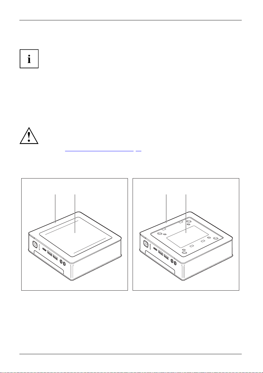
Fitting the underside cover (device dependent)
Type rating plate
FUJITSU Desktop ESPRIMO Q95x:
When your device is delivered, the lower cover (2) is not yet installed on the underside
of the device, instead it is enclosed with the system, so that you can see the type
rating plate (3) and the software licence information during the initial start-up.
The type rating plate and the softwa re licence are affixed on the device cover and
are normally not visible underneath the installed lower cover.
FUJITSU Desktop ESPRIMO Q55x:
With the FUJITSU Desktop ESPRIMO Q55x, the type rating plate is attached to the
underside of the device or to the right side of the device (w hen used vertica lly).
FUJITSU Desktop ESP
Only fit the undersi
vertical operatin
Section "
If you are fitting t
must not fit the und
attachment will
e with device cover (1), with installed lower
Devic
(2)
cover
Setting u
de cover if you are u sing the device in a horizontal or
g position without attaching it to a VESA interface (see
p the device", Page 18).
he device onto the VESA interface of a monitor, you
erside cover. If you do, the screw holes for the VESA
no longer be accessible.
21 31
RIMO Q95x:
e with device cover (1) and visible type
Devic
(3, ESPRIMO Q95x only), no underside
plate
.
cover
The device is equipped with a d evice cover (1) on the underside. The device cover is divided
into two: during operation, the lower cover (2) is inserted in the device cover.
16 Fujitsu
Page 21
Getting started
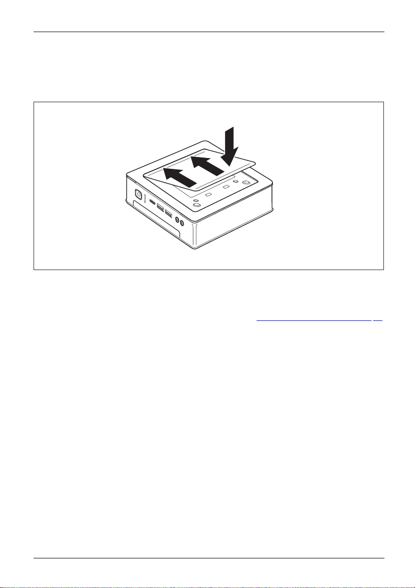
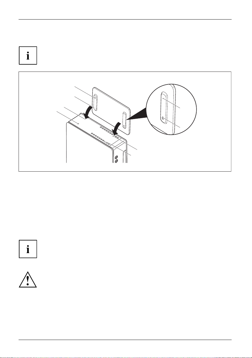
To install the lower cover before the initial start-up and to be able to use the
device for the first time, proceed as follows:
► Turn the device over and place it on a stable, flat and clean surface. If necessary, lay an
anti-slip cloth on this surface to prevent the device from being scratched.
2
1
1
► Place the lower cove r on the underside of the device as shown.
► Hook the lower cover into the openings provided for it on the underside (1).
► Fold the cove r in the direction of the arrow (2), until you feel and hear it engage.
You wil l find information on removing the lower cover in section "
Remove the lower cover", Page 23.
Fujitsu 17
Page 22
Getting started
Setting up the device
WorkstationErgonomicDevice
Operating position
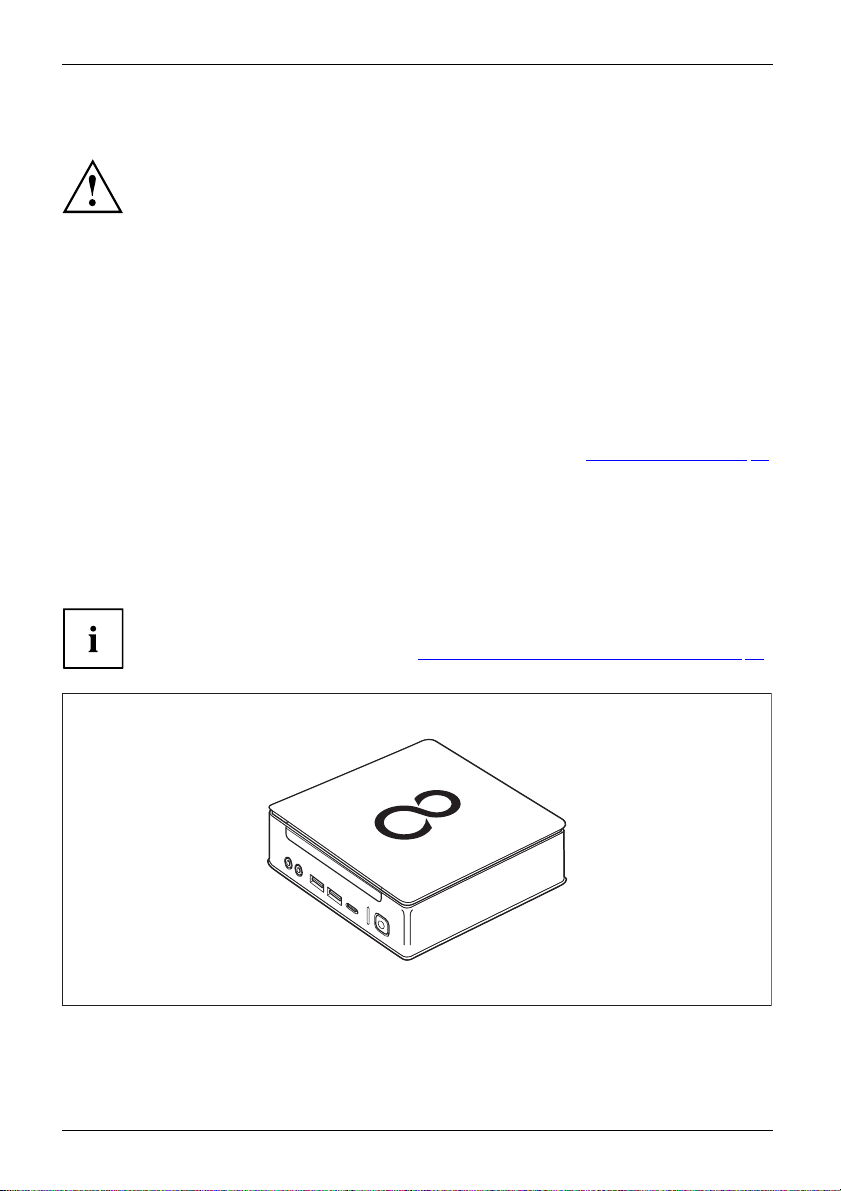
You can use the device in various operating positions:
Horizontal, top casing cover upwards
When installing your device, please read the recommendations and safety
notes in the "Safety/regulations" manual.
We recommend that you place your device on a surface which is not slippery. In
view of the many different finishes and varnishes used on furniture, it is possible
that the rubber feet will mark the surface they stand on.
Depending on the location of your device, both ersome vibrations and noises m a y occur.
To prevent this, a distance of at least 10 mm / 0.39 inches should be maintained
from other devices on casing sides without ventilation surfaces.
In order to avoid overheating, do not cover the ventilation areas
of the monitor or the device.
A minimum distance of 200 mm / 7.87 inches from the device must
be observed for ventilation areas.
Do not stack several devices on one another and do not stand a monitor on the device.
Do not expose the device to extreme ambient conditions (see "
section "Ambient conditions"). Protect the device against dust, humidity and heat.
With the FUJITSU Desktop ESPRIMO Q55x de vice version, you will need to affixthe
adhesive feet you were supplied with to the four corners of the underside of the device
in this operating position (see Section "
Attaching the adhesive feet (optional)", Page 21).
Technical data", Page 89,
18 Fujitsu
Page 23
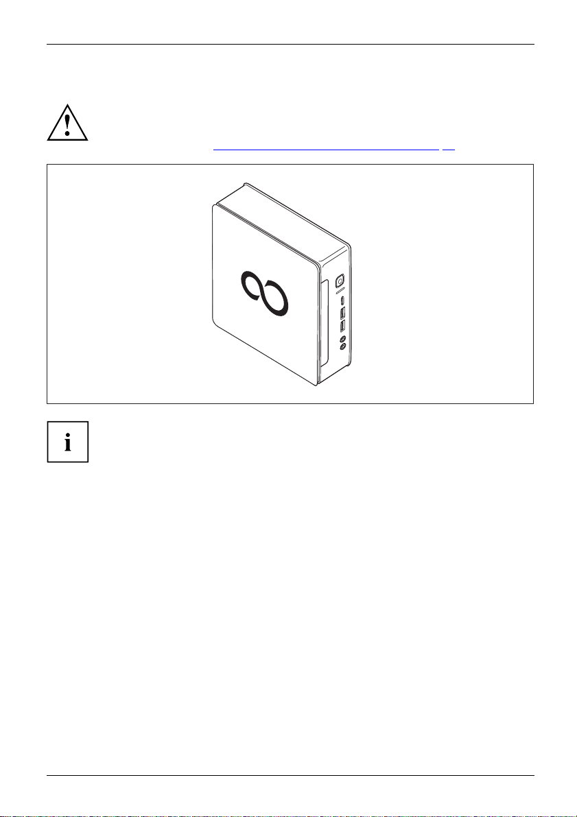
Vertical with no base, ON/OFF switch facing upwards
If you are not using a base, you will need to affix the adhesive feet you w ere
supplied with to the four corners of the left side of the device (side with screw holes
for attaching the base). Affix the adhesive feet in such a way that no fan vents are
covered (see S ection "
Attaching the adhesive feet (optional)", Page 21).
Operation in th e vertical operating position is not allowed in Taiwan.
Getting started
Fujitsu 19
Page 24
Getting started
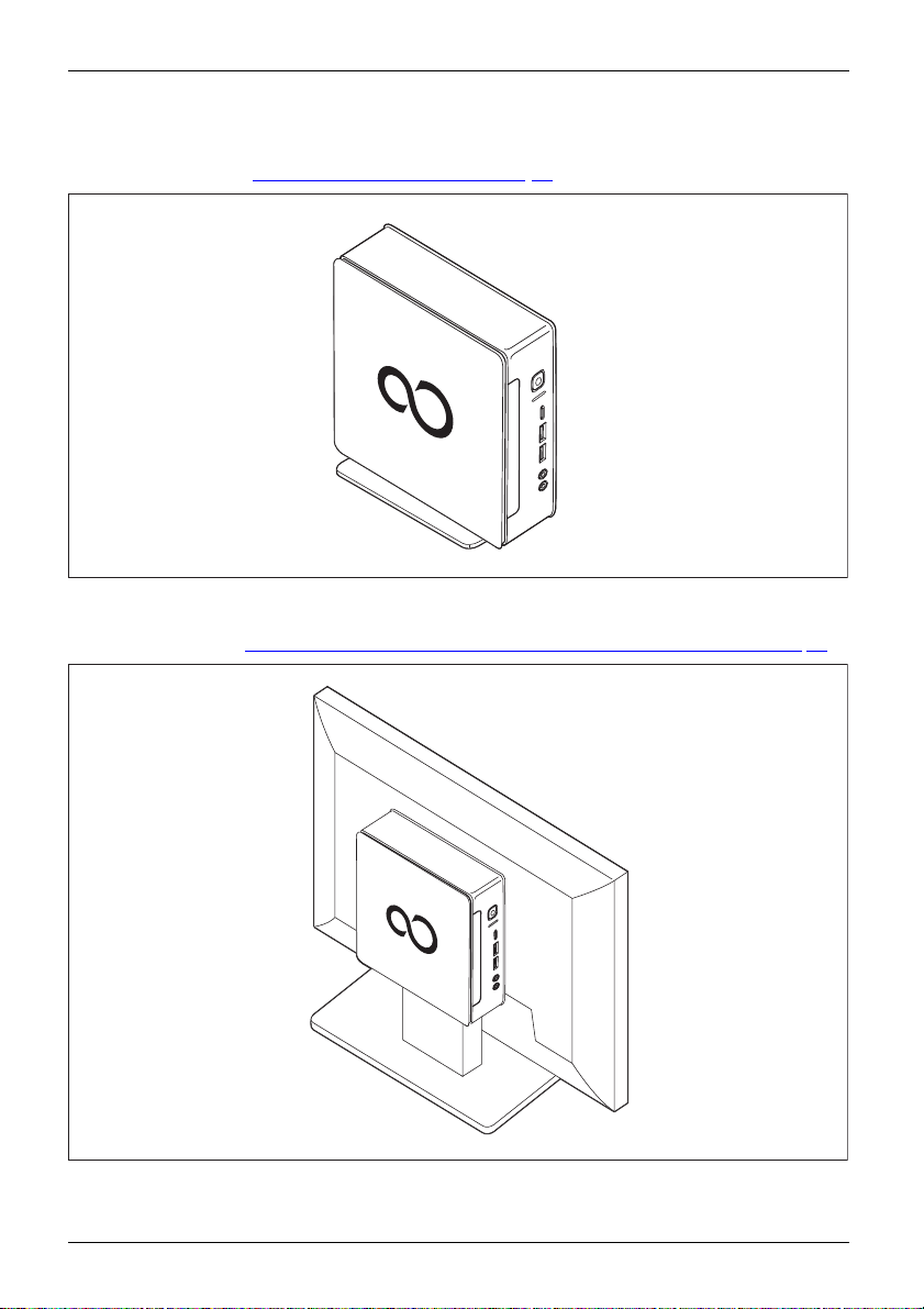
Vertical with base, ON/OFF switch facing upwards
For fitting see Section "
Fitting the base (optional)", Page 22
On the VESA interface of a monitor, ON/OFF switch facing upwards
For fitting see Section "
Fitting the device to the VESA interface on a monitor (optional)", Pag e 22
20 Fujitsu
Page 25
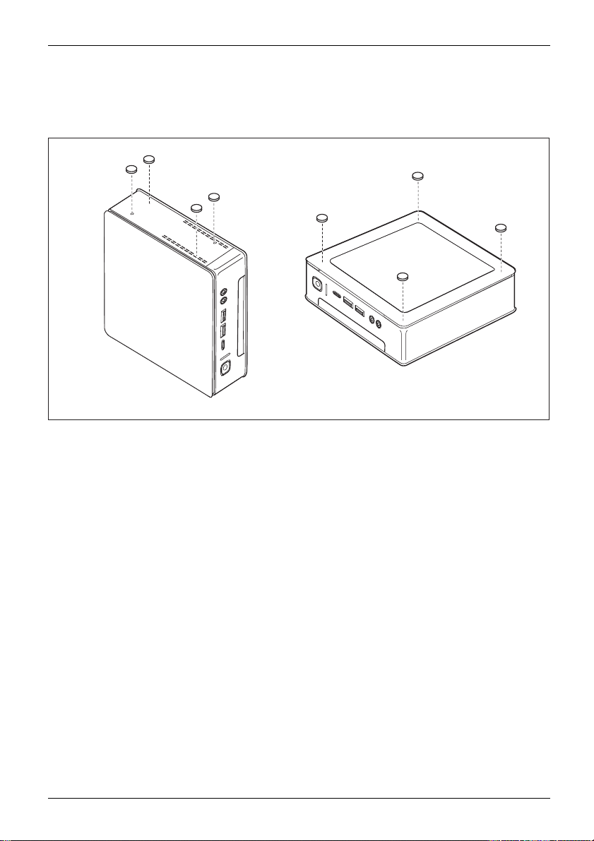
Attaching the adhesive feet (optional)
With the horizontal and vertical operating positions with no base, you will need
to attach the adhesive feet to the device.
1
1
1
1
2
2
2
Getting started
2
► Vertical opera
of the left sid
Affix the adhes
► Horizontal operating position with no base: Position the adhesive feet on the four
corners of the underside of the device as illustrated (2).
Fujitsu 21
ting position with no base: Position the adhesive feet on the four corners
e of the device as illustrated (side with screw holes for attaching the base).
ive feet in such a way that no fan vents are covered.
Page 26
Getting started
Fitting the base (optional)
Screw holes for attaching the base can only be found on the left side of the device.
4
3
2
1
1
2
► Place the devic
The screw holes (1) and guide openings (2) for securing t he base on the
left side of the device are facing upwards.
► Place the base
correspondin
► Place the screws into the overlapping screw holes (1 & 4) and attached
the base to the device using the screws.
e on the right side as shown.
on the left side of the device such that the locking lugs (3) are inserted into the
g guide openings (2) on the device and the screw holes (1) and (4) directly overlap.
3
4
Fitting the device to the VESA interface on a monitor (optional)
With ESPRIMO Q95x type devices, the casing cover is already fitte d with
the corresponding screw holes as standard.
With ESPRIMO Q55x type devices, you can order the corresponding casing
cover with screw holes separately if necessary.
The device must be fitted onto the screen in such a way that the connecting
and operating elements can be used from the side.
22 Fujitsu
Page 27
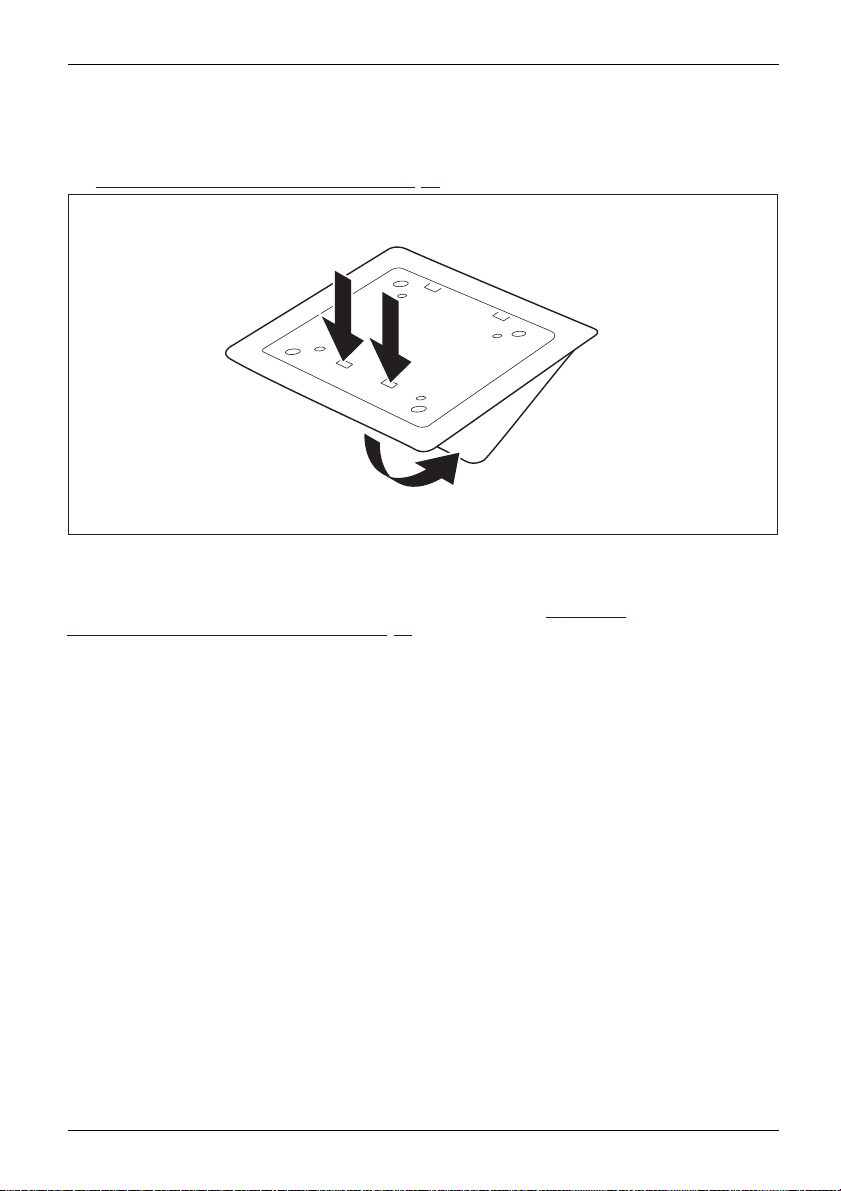
Remove the lower cover
• Requirement: The casing is open and the casing cover is removed (see
Removing the bottom casing cover", Page 85).
"
1
1
2
► Release the locking lugs (1) on the underside cover from the casing cover
and remove the underside cover (2).
You will find information on securing the lower cover in section "
underside cover (device dependent)", Page 16.
Fitting the
Getting started
Fujitsu 23
Page 28
Getting started
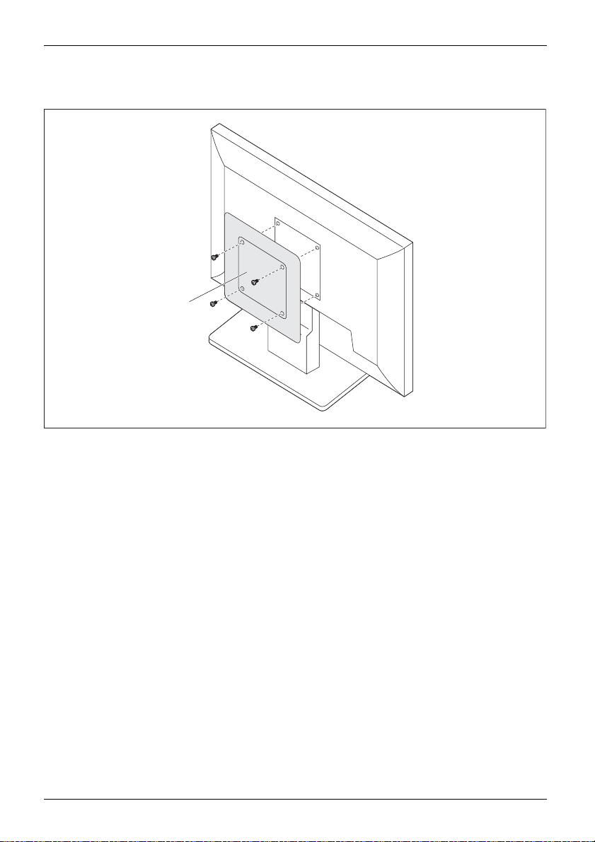
Mounting with screws
a
1
1
1
1
► Install the ca
24 Fujitsu
sing cover (a) on the r ear of the monitor using the screws supplied (1).
Page 29
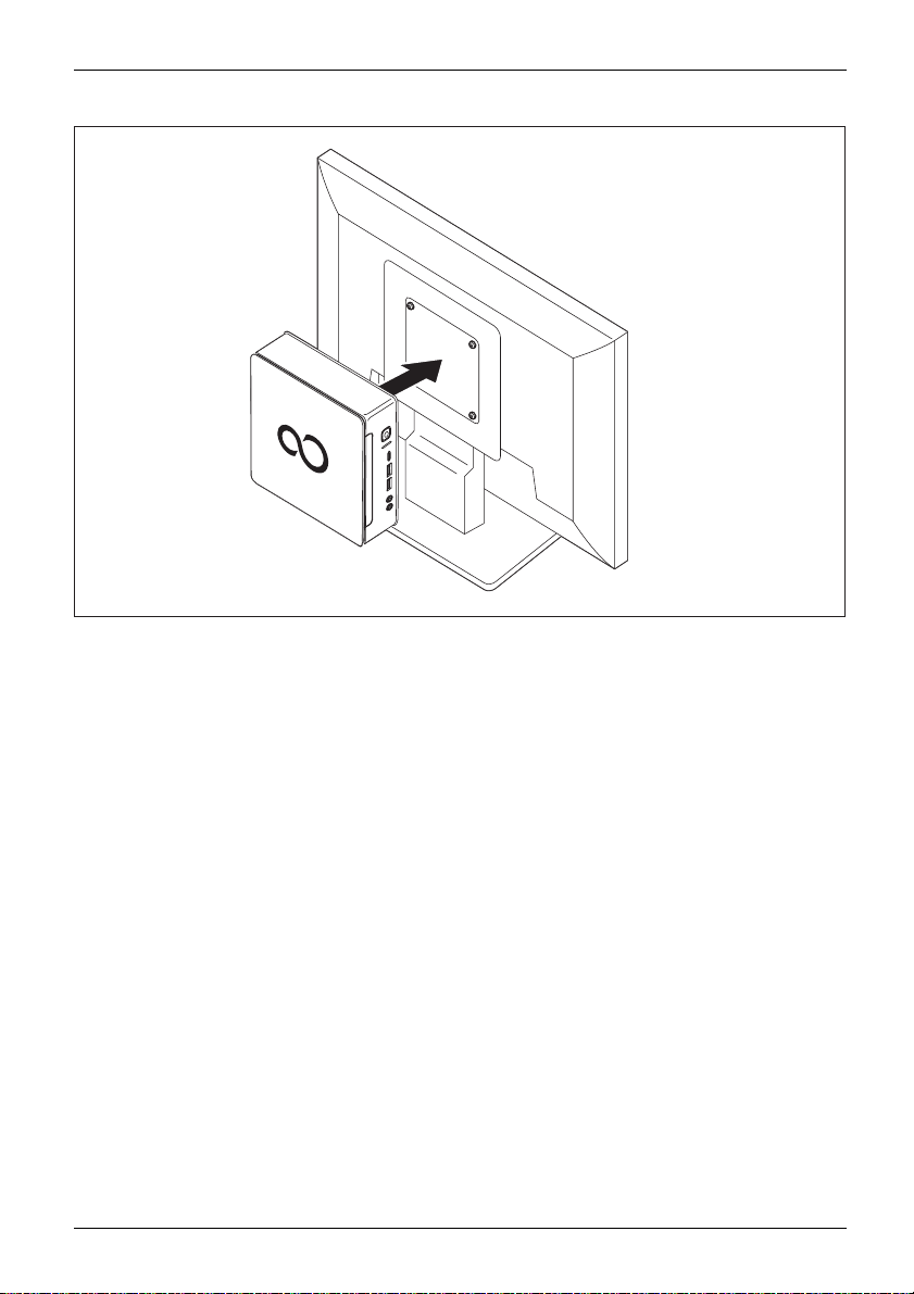
► Secure the de vice on the casing cover mounted on the monitor.
Getting started
Fujitsu 25
Page 30
Getting started
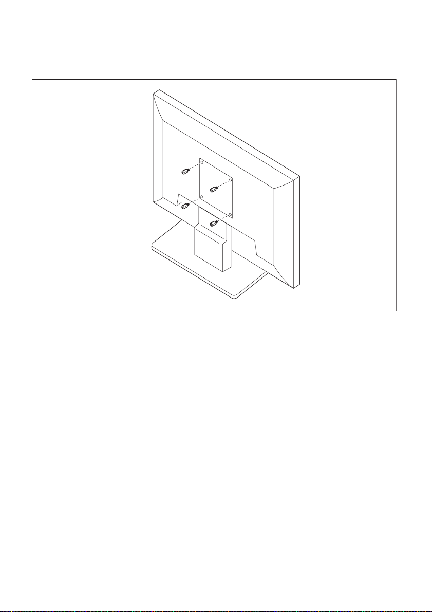
Mounting with bolts and screws
1
1
1
1
► Screw in the fo
26 Fujitsu
ur hexagon head bolts at the rear of the monitor (1).
Page 31

Getting started
1
1
a
1
1
► Install the casing cover (a) into the bolts at the rear of the monitor using the screws supplied (1).
Fujitsu 27
Page 32

Getting started
► Secure the device on the casing cover mo unted on the monitor.
Mounting on monitors with height-adjustable column
► Detach all cables from the monitor.
► Fix the monitor base adapter by laying the
velcro tape around the monitor base (1) and
looping it back through the metal eye (2).
2
2
1
28 Fujitsu
Page 33

Getting started
2
► Install the casing cover onto the base
adapter using the screws supplied (1).
1
1
1
1
► Secure the device on the casing cover
mounted on the monitor.
Fujitsu 29
Page 34

Getting started
Connecting the power cable
PreparingforoperationPowercable
Observe the safety notes in the enclosed "Safety/Regulations" manual.
The supplied power cable conforms to the requirements of the country in
which you purchased your device. Make sure that the power cable is approved
for use in the country in which yo u intend to use it.
Use the following table to check which mains plug applies for your country. The
following illustration may be different from your country variant.
1
2
► Connect the power cable (1) to the power connection (AC IN) of the device.
► Plug the mains cable (2) into a mains outlet.
30 Fujitsu
Page 35

Getting started
Power connection
Country
USA, Canada, Mexico, parts of So
Japan, Korea, the Philippines,
Russia and the Commonweal
States (CIS), large parts
South America, the Middl
Hong Kong, India, large p
of Europe, parts of
e East, parts of Africa,
arts of South Asia.
uth America,
Ta i w a n
th of Independent
UK, Ireland, Malaysia, Singapore, parts of Africa
China, Australia, New Zealand
Fujitsu 31
Page 36

Getting started
Connecting external devices
Read the documen tation on the external device before connecting it.
With th e exception of USB devices, always remove all power plugs
before connecting external devices!
Do not connect or disconnect cables during a th understorm.
Always take hold of the actual plug. Never unplug a cable by pulling the cable itself.
Ports on the device
PortsExternaldevicesDevice
The ports are located on the front and rear side of the device. The ports available on
your device depend on the configuration level you have selected. The standard ports are
marked with the symbols shown below (or similar). Detailed information on the location
of the ports is provided in the manual for the mainboard.
DVI-D monitor port, white
Monitorport
DP DisplayPort
Serial interface
Serialinterface
USB 2.0 - Universal Serial
Bus, type A, black
lBus
UniversalSeria
USB 3.1 - Universal Serial Bus,
type A: blue, type C: black
PS/2 keyboard port, purple
t
Keyboardpor
LAN port
LANport
Audio input (Line in)
Audio output (Line Out), light green
AudiooutputLineout
Some of the connected devices require special software (e.g. drivers) (refer to the
documentation for the connected device and operating system).
32 Fujitsu
Page 37

Getting started
Connecting a monitor
Only attach the screen to you r device when switched off.
Only use high-quality signal cables when connecting screens.
► Follow the instructions contained in the monitor m anual to prepare the
monitor fo r use (e.g. connect the cables).
Monitor
► Plug the data cable into the desired monitor port of the device.
► Plug the monitor power cable into a grounded mains outlet.
Connecting a USB mouse
► Connect the USB mouse to one of the USB ports on the device.
ConnectingaUSBmouseUSBport
Connecting a USB keyb
Only use the keyboard cable supplied with th e keyboard (not within the delivery scope of the device).
USBportConnecting
► Plug the rectangular connector of the keyboard cable into the rectangular socket
on the underside or on the rear of the keyboard.
► Insert the flat rect
USBport
Connecting external devices to the serial interface
SerialinterfaceSerialinterface,Externaldevices,Devices,
External devices (e.g. a printer or scanner ) can be connected to the serial port.
► Connect the data cable to the external device.
► Connect the data cable to the corresponding serial interface.
For an exact description of how to conne ct external devices to the co rresponding
port, please see the external device documentation.
angular USB plug of the keyboard cable into a USB port of the device.
oard
Port settings
erface,
Serialint
Device dri
Devicedrivers,
Fujitsu 33
You can change the port settings (e.g. address, interrupt) in the BIOS Setup.
vers
The devices connected to the serial interface require drivers. Your operating system
already includes many drivers. If the required drive is missing, install it. The latest
drivers are usually available on the Internet or will be supplied on a data carrier.
Page 38

Getting started
Connecting external devices to the USB ports
USBdevices,USBport,Externaldevices,D evices,
You can connect a wide range of external devices to the USB ports (e.g.
printer, scanner, modem or keyboard).
USB devices are hot-pluggable. Th is means you can connect and disconnect
USB cables while your device is switched on.
Additional information can be found in the documentation for the USB devices.
► Connect the data cable to the external device.
► Connect the data cable to one of the USB ports on your device.
Device drivers
The external USB devices that you connect to one of the USB ports usually
require no driver of their ow n, as the required software is already included
in the operating system. If the device requires separate software, please
note the information in the manufacturer’s manual.
Connecting the PS/
Only use the supplied lead.
A PS/2 device is only recognised by the PC if you connect t he PS/2 device
when the PC is switched off and then switched on again.
ConnectPS/2deviceConnect
► Connect the PS/2 device to the PS/2 port on the PC.
► Switch the PC back on.
2device
34 Fujitsu
Page 39

Getting started
Switchingonforthefirst time: installing the software
Installing,Software,Installing,
Once the installation ha s been started the device must not be switched
off, unless the installation has been completed.
During installation, the device may only be rebooted when you are requested to do so!
The installation will otherwise not be carried out correctly and th e contents
of the hard disk must be completely restored.
If the device is integrat
the network protocol ar
Contact your network ad
When you switch on the d
is installed and config
as this process must n
You m a y need the Win
number as a sticker
dows licence number during the installation. You will fin d the licence
on your device (see "
ed into a network, the user and server details as well as
e required during the software installation.
ministrator if you have any questions about these settings.
evice for the fi rst time, the supplied software
ured. Plan a reasonable amount of time for this,
ot be interrupted.
Remove the lower cover", Page 23).
Switch on the m on itor and the machine
In order to avoid overheating, do not cover the ventilation areas
on the monitor or the device.
► Switch on the monitor (see operating instructions for the monitor).
► Pres
Fujitsu 35
s the on/off button on the front of the machine.
The operational display will light up and the machine will start.
Page 40

Getting started
Installing the software
► During installation, follow the on-screen instructions.
Software,Installing,
► If anything is unclear regarding the data you are asked to input, read the
online Help in your operating system.
You will find more information on the system, as well as drivers, utilities and updates on
the "Drivers & Utilities" DVD and on the Internet under "
http://www.fujitsu.com/fts/support".
36 Fujitsu
Page 41

Operation
Switch the device on
► If necessary, switch the monitor on (see the operating manual for the monitor).
DeviceMonitor
► Press the ON/OFF switch on t
The power indicator glows and the device is started.
Switching off the device
► Shut down the operatin
Device,Monitor,
► If the operating system does not automatically switch the device into energy-sa ving
mode or switch it off, press the ON/OFF switch until the device switches off.
Warning, this could lead to a loss of data!
If the device is swi
The ON/OFF switch
completely disco
► If necessary, switch the monitor off (see the operating manual for the monitor).
tched off, the device consumes a minimum of energy.
he front of the device.
gsysteminadefined manner.
does not disconnect the device from the mains voltage. To
nnect the mains voltage, remove the power plug from the power socket.
Operation
Fujitsu 37
Page 42

Operation
Indicators on the device
The indicators are on the front of the casing. Which indicators are available on your
device depends on the configuration level you have selected.
Example: Device variant with SmartCard reader and/or palm sensor:
321
No. indicator Description
1
SmartCard read
indicator (dev
dependent)
2Harddiskindi
3 Power-on in
ice
cator
dicator
er
The indicato r l
accessed (devi
The i ndicator
is being acce
Caution:In energy saving mode, the d evice must not be
disconnected from the mains supply as this can cause loss of data.
• The indicator is illuminated:
The device is switched on.
•Theindicatorisflashing:
The device is in energy-saving mode. After being switched on
with the ON/OFF switch, the device powers up or returns to the
state it was in before it entered energy-saving mode.
• The indicator is not illuminated:
The device is switched off (disconnected from the mains) or is
ready to operate. If the device is ready to operate, it can be
switched on with the ON/OFF switch.
ights up when the device’s SmartCard reader is
ce dependent).
lights up when the hard disk drive in the device
ssed.
In energy-saving mode the device must not be disconnected from th e
mains supply, as data loss may occur.
38 Fujitsu
Page 43

Keyboard
KeyboardKeyboard,Keyboard,Keyboard,Keyboar d,KeyboardAlphanumerickeypadCursorkeysKeys ,FunctionkeysNumerickeypadNumerickeypad
The illustrated keyboard is an example and may differ from the model you use.
Operation
1 2
345
1 = Function keys
2 = On/off switch (optional)
4=Cursorkeys
5 = Numeric keypad (calculator keypad)
3 = Alphanumeric keypad
Important k
KeysKeyb oardshortcuts
eys and keyboard shortcuts
The description of th e following keys and keyboard shortcuts applies to Microsoft
operating systems. Details of other keys and keyboard shortcuts can be found in
the documentation for the relevant application program.
Key / key combination Description
tch
ON/OFFswi
Button,
On/off switch ( optional)
Depending on the setting in the BIOS Setup, the device can be switched
on or off with this switch. Some operating systems allow you to configure
additional functions of the ON/OFF switch in the Control Panel.
With some keyboards the ON/OFF switch can only be used with an ACPI
(Advanced Configuration and Power Management Interface). Otherwise
the key is inoperative. The mainboard must support this function.
Keys,Keys,Keys,
Enter key
confirms the highlighted selection. The Enter key is also referred to as
the "Return" key.
Fujitsu 39
Page 44

Operation
Key / key combination Description
Keys,
Windows key (device dependent:
calls up the Windows Start menu
Keys,
Menu key (device dep end ent: v
calls up the menu for the marke
Keys,
Windows key (device depen
The Windows key switches b
application used.
Keys,
Menu key (device dependent: variant 2)
The Menu key calls up the menu for the active application.
Keys,Keys,
Shift key
enables upper-case
Keys,
Alt Gr key (country
produces a charac
sign on the
Keys,
Num Lock key
By p ressing the
lower-case lev
When the Num Lo
keys are activ
When the Num L
Numeric keyp
Keys,KeysKeysKeys,
Ctrl key
Ctrl
performs a special operation when pressed in conjunction with another
key. The
Ctrl+Alt+DelCtrl+Alt+DelKeyskeyboardshor tcuts
Ctrl
Windows S ecurity/Task Manager
AltCtrl
++
Del
This key comb ination opens the Windows Security/Task Manager window.
variant 1)
.
ariant 1))
d item (Windows).
dent: variant 2)
etween the main screen and the last
letters and the upper key symbols to be displayed.
dependent)
ter shown on the bottom right of a key (e.g. the @
Q
key).
Num Lock key you switch between the upper- and
els of the calculator keypad.
ck indicator is lit the numeric keypad and arithmetic
e.
ock indicator is n ot lit the cursor con trol functions on the
ad are active.
key is also called the "C ontrol" or "Control key".
40 Fujitsu
Page 45

Optical drive (device dependent)
Opticaldrive
Handling d ata carriers
Handling
Observe the following guidelines whe n handling data carriers:
• Avoid touching the surface of a data carrier. Only handle data carriers by their edges.
• Always store data carriers in their cases. This will protect the data carrier against
• Protect your data carriers against dust, mechanical vibrations and direct sunlight.
• Avoid storing a data carrier in areas subject to high temperatures or humidity.
You may use 12 cm diameter data carriers in the drive. Do not use any business
card CDs or other small data carriers.
When using a data carrier of lesser quality, vibrations and reading errors may occur.
Depending on the device variant, your device is fitted with an optical drive.
An optical drive on one side and a SmartCard reader/palm sensor on the
other cannot be combined with one another.
This product contains a light emitting diode, classification according to IEC 60825
1:2007: LASER CLASS 1, and must therefore not be opened.
being covered in dust, scratched or damaged in any other way.
Operation
Fujitsu 41
Page 46

Operation
Inserting or removing a data carrier
► Press the Insert/Eject button to open the tray.
The drive tray will open.
► Place the data carrier in the tray with the
printed side facing upwards.
1
or
► Remove any data carrier already
in there.
2
If you press
being acces
until the p
42 Fujitsu
the Eject button while the data carrier in the optical drive is
sed, the data carrier will not b e automatically ejected. Wait
rocess has finished, then try it again.
Page 47

Manual removal of data carriers (emergency removal)
CD/DVDRemoving byh and, CD/DVDEmergencyremoval,CD/DVD
In th e event of a pow er failure or damage to the drive it may be necessary
to manually remove the CD/DVD.
► Switch your device off.
► Push a pen or a piece of wire (such as a
paperclip) firmly into the opening (1).
The drive tray is ejected. You can now pull
the drive tray (2) out of the drive.
2
1
Wireless LAN / Bluetooth wireless components (device dependent)
The installation of wireless components not approved by Fujitsu will
invalidate the certifications issued for this device.
Operation
The operation of these wireless components is not allowed in Taiwan.
Switching the wireless components on and off
You can use the Device Manager program to switch the radio
components on and off individually.
Pay attention to the additional safety notes for devices with radio components
provided in the "Safety/Regulations" manual.
Details on using Wireless LAN can be found in the online help system
included with the Wireless L AN software.
You ca n find more information on how to use Bluetooth on the CD you
received with your Bluetooth software.
Fujitsu 43
Page 48

Operation
Settings in BIOS Setup Utility
BIOSSetupUtilitySystemsettings,BIOSSetupUtilityConfiguration,BIOSSetupUtilitySetupSystemconfigurationHardwareconfigu rati on
The BIOS Setup Utility allows you to set the system functions and the
hardware configuration for your device.
When it is supplied, the device is set to factory default settings. You can change
these settings in the BIOS Setup Utility menu. Any changes you make take effect
as soon as you save and exit the BIOS Setup Utility.
The BIOS Setup Utility program contains the following menus:
Menu Description
Main
Advanced
Boot
Power
Security
Exit
System settings such as
Advanced system setti
Configuration of the start-up sequence
Energy saving function
Password sett ings
Exits the BIOS Set
The following function keys can also be used:
Key Description
Esc
To e xi t th e BIOS Setup Utility.
The curre nt settings are not saved.
F7
To reject changes and load the previous configuration of the BIOS Setup
Utility.
F9
F10
To l o a d t h e d
To e xi t th e
The cur ren
efault configuration of the BIOS Setup Utility.
BIOS Setup Utility.
t settings are saved.
time and date
ngs
and security functions
up Utility
Startin
► Reboot the device (switch off/on or reboot the operating system).
g the BIOS Setup Utility
BIOSSetupUtility
ing on the Fast Boot setting in the BIOS Setup utility,thefollowing
Depend
ation may appear on the screen during start:
inform
<F2> BIOS Setup <F12> Boot Menu
► Press the function key
► If a p
assword has been assigned, enter the password and press the Enter key.
u have forgotten the password, contact your system administrator
If yo
ontact our customer service centre.
or c
F2
.
The BIOS Setup Utility starts.
44 Fujitsu
Page 49

Operation
Operating BIOS Setup Utility
BIOSSetupUtility
Press the
F1
key to disp lay help on the operation of the BIOS Setup Utility. The description
of the individual settings is sh own in the right-hand window of the BIOS S etup Utility.
With the
► Use the cursor keys
The menu is displayed on the screen.
► Select the option you want to change with the cursor keys
F9
key you can load the default settings of the BIOS Setup Utility.
←
→
or
to select t he menu you wish to access to make c hanges.
↑
or↓.
► Press the Enter key.
► Press the
ESC
key to exit the selected menu.
► For future reference, make a note of the changes you have made (for example, in this manual).
Exiting BIOS Setup Utility
BIOSSetupUtility
You need to select the desired option in th e Exit menu and activate it by pressing the Enter key:
Exit Saving Changes - save changes and exit BIOS Setup Utility
► To save the current menu settings and exit the BIOS Setup Utility,selectExit Saving Changes and Yes.
The device is rebooted and the ne w settings come into effect.
Exit Discarding Changes – Discard changes and exit BIOS Setup Utility
► To discard the changes, select Exit Discarding Changes and Yes.
The settings which applied when BIOS Setu p Utility wascalledupremaineffective.
The BIOS Setup Utility is terminated and the device is rebooted.
Fujitsu 45
Page 50

Operation
Property and data protection
PropertyprotectionDataprotectionSecuritymeasures
Software functions and mechanical locking offer a broad range of functions for protecting your device
and your personal data against theft and unauthorised access. You can also combine these functions.
BIOS Setup security functions
The Security menu in the BIOS Setup offers you various options for protecting your
personal data against unauthorized access, e.g.:
• Prevent unauthorised access to the system
• Prevent unauthorized access to the BIOS Setup
Before using the various options for password protection in the BIOS Setup utility
to increase data security, please observe the following:
Make a note of passwords and keep them in a safe place. If you forget your supervisor
password you will no longer be able to access your device. Deleting passwords is
not c overed by your warranty and a charge will be made for assistance.
on
Passwordprotecti
Your password can be
and numbers. No dis
a maximum of 32 characters long and can consist of letters
tinction is made between uppercase and lowercase.
Using the SmartC
Securityfunctions,Securityfunctions
ard reader (device dependent)
Whether your device has a SmartCard reader depends on the
device variant you have ordered.
The SmartCard reader allows access to be limited to only those users that
have an appropriate SmartCard.
SmartCards are not supplied as standard equipment. You can use all SmartCards that comply with
the ISO standard 7816-1, -2 or -3. These SmartCards are available from various manufacturers.
With the appropriate software you can use your SmartCard as an alternative to password protection,
but also as a digital signature, fo r encrypting your e-mails or for home banking.
We recommend that you always use two SmartCards. Always keep one of the SmartCards
in a safe place if you are carrying the other SmartCard with you.
In order to be able to take advantage of all the security features of your system, you
will need a CardOS SmartCard from Fujitsu Technology Solutions.
The SmartCard can only be used with a PIN, offering maximum protection even if
you lose the SmartCard. In order to maximise your security, the CardOS SmartCard
is disabled if three incorrect attempts are made to enter the P IN.
When you use the CardOS SmartCard for the first time, you will either need to enter the
preset PIN "12345678" or the PIN given to you by your systems administrator.
46 Fujitsu
Page 51

Fitting a SmartCard reader
Fit the SmartCard reader as described in section "Installing and removing the
SmartCard reader and palm sens or (device dependent)", Page 73.
Inserting the SmartCard
Do not use force when inserting and removing the SmartCard.
Make sure that foreign objects do not fall into the SmartCard reader.
Operation
1
► Push the SmartCard into the SmartCard reader with the chip facing upwards.
Fujitsu 47
Page 52

Operation
Using a palm sensor (device dependent)
Whether your device has a palm sensor depends on the device variant you have ordered.
The palm sensor (1) can record the image of the pattern of the veins in the hand. This image
is evaluated by additional software and can be used instead of a passw ord.
1
Fitting a palm sensor
Fit the palm sensor as described in Section "Installing and removing the SmartCard
reader and palm sensor (device dependent)", Page 73.
Using the palm sensor
► To be able to use the palm sensor, you mu st install and launch the software.
► Follow the instructions on the screen.
The surface of the hand must be positioned such that the palm of the hand
lies centrally over the palm sensor. In doing so, the palm of the hand and
slightly spread fingers should form an even surface.
The supplied software shows the precise position of the hand above the palm sensor.
48 Fujitsu
Page 53

Using the Security Lock
The following illustration shows the FUJITSU Desktop ESPRIMO Q95x device
variant. You will find the security lock device in the same position in the
FUJITSU Desktop ESPRIMO Q55x device variant.
Your device has provision for a security lock (1). You can use the security lock device
and the Kensington Lock cable (steel cable, accessory) to protect your device against
theft. Please consult the manual for your Kensington Lock.
1
Operation
► Attach the Ken
UsingtheKensingtonLockCableSecurityLockMechanicalsafeguardMechanica l safeguardAnti-theftprotection
sington Lock cable to the Security Lock mechanism (1) on your device.
Fujitsu 49
Page 54

Operation
Using a locking bracket
• The top casing cover has been removed (see "Removing the top casing co ver", Page 63).
• The bottom casing cover has been removed (see "
the top casing cover", Page 85).
You can also purchase a locking bracket for your device. Contact the service
desk or sales partner responsible for your country.
The following illustration shows the FUJITSU Desktop ESPRIMO Q95x device
variant. You will find the components concerned in the same position in the
FUJITSU Desktop ESPRIMO Q55x device variant.
Removing and attaching
You can use the padlock c
protect your device fro
m unauthorised opening.
lamp located on the device and the locking bracket to
50 Fujitsu
Page 55

► Pull the locking bracket apart slightly (1).
PadlockclampLocking bracketMechanicalsafeguardMechanicalsafeguard
Operation
1
1
2
3
3
2
► Insert the locking bracket into the eyes (2) in the direction of the arrow (3).
► Secure the bottom casin g cover again, see "
► Secure the top casing cover again, see "
Securing the bottom casing cov er", Page 86.
Securing the top casing cover", Page 64.
Fujitsu 51
Page 56

Operation
► Fold the locking bracket fully to the right until it is lying against the side of the
device and secure a padlock to th e padlock clip.
Alternatively you can use a Kensington Lock cable (see "Using the
Security Lock", Page 49). This will prevent unauthorised opening of the
locking bracket and, with it, the casing cover.
Lead-sealing t he casing
To prevent unauthorised persons from opening casing, you can lead-seal it.
► Use the wire of the lead-seal to connect the locking bracket with the padlock clip
on the back of the device (see chapter "
ngchain
ngwire
safeguard
Lead-sealingLead-seali
Lead-seali
Mechanical
► Use the seal to secure the lead-sealing chain or wire.
Rear", Page 11 ).
52 Fujitsu
Page 57

Troubleshooting and tips
Refer to the safety notes in the "Safety/regulations" manual and in the "Gettin g
started", Page 15 chapter when connecting or disconnecting cables.
Troubleshooting and tips
If a fault occurs, try to c
• in this chapter
• in the documentation for the connected devices
• in the help systems of th
• in the documentation for your operating system
orrect it as described in the following documenta tion:
e software used
Help if problems occur
Should you encount
► Note the ID number
plate under the ty
the underside cov
rating plate cov
► Contact the Service Desk responsible for your country for clarification of the problem:
"
http://support.ts.fujitsu.com/contact/ser vicedesk". When you do this, please have
ready the ID number and serial number of your system.
er a problem with your computer that you cannot resolve yourself:
of your device. You will find the ID number on the typ e rating
pe rating plate cover on the underside of your device (see "
er (device dependent)", Page 16). If necessary, remove the type
er to be able to gain access to the ID number.
Fitting
Troubleshooting
Power-on indicator remains u nlit after you have switched on your device
Cause
The mains voltage supply is faulty. ► Check that the power cable is properly
Internal power supply overloaded.
Troubleshooting
plugged into the device and into the mains
socket.
► Unplug the power plug of the device from
the m ains socket.
► Wait ap
► Plug the power plug of the device into the
► Switc
prox. 3 min.
mains socket again.
h the device on.
Fujitsu 53
Page 58

Troubleshooting and tips
The device cannot be switched off with the ON/OFF switch.
Cause
System crash ► Keep the on/off switch pressed for at least 4
Remedy
seconds until the machine switches off.
Caution: This can lead to a loss of data!
This procedure does not allow the operating
system to shut down in an orderly way. The next
time the system is started there may well be
error messages.
Monitor remains blank
Cause
Monitor is switched off. ► Switch your monitor on.
Power saving has been activated (screen is
blank)
Brightness control is set to dark ► Adjust the brightness control. For detailed
Power cable not connected
Monitor cable not connected
Wrong m
onitor settings
Remedy
► Press an y key on the keyboard.
or
► Deactivate the screen saver. If
necessary, enter the appropriate
password.
information, please refer to the operating
manual supplied with your monitor.
► Switch off the monitor and the device.
► Check that the monitor power cable is
properly connected to the monitor and to
a grounded mains outlet or to the monitor
socket of the device.
► Check that the device po wer cable is
properly plugged into the device and a
grounded mains outlet.
► Switch on the monitor and the device.
► Switch of
► Check that the monitor cable is properly
connected to the device and monitor.
► Switch o
► Restar
► Press
► Start
► Set the correct values for the connected
monitor as described in the operating
manual of your mon itor.
f the monitor and the device.
n the monitor and the device.
t the system.
8
F
while the system is booting.
the system in Safe Mode.
54 Fujitsu
Page 59

No mouse pointer displayed on the screen
Cause
The mouse is not correctly connected.
Remedy
► Shut down your operating system in the
proper mann er, for instance using
Alt+Del
► Switch the device off.
► Check that the mouse cable is properly
connected to the system unit. If you use an
adapter or extension lead with the mouse
cable, check the connections.
► Make sure that only one mouse is
connected.
► Switch the device on.
.
Time and/or date is not correct
Cause
Time and date are incorrect.
Remedy
► Set the correct time and date within the
operating system you are using.
or
► Set the correct time and/or date in the
BIOS Setup.
Troubleshooting and tips
Ctrl
+
SmartCard reader is not recognised.
Cause
Chip ca rd inserted incorrectly.
SmartCard
Cause
PIN forgotten ► If you are wo rking in a network, contact your
Fujitsu 55
PIN forgotten
Troubleshooting
► Make sure you have inserted y our
SmartCard into the SmartCard reader with
the chip facing upwards.
► Check whethe
is supporte
with the ISO
Troubleshooting
system administrator, who can unlock your
system with a Supervisor PIN.
r the SmartCard you are using
d. Your SmartCard must comply
standard 7816-1, -2, -3 and -4.
Page 60

Troubleshooting and tips
SmartCard lost
Cause
SmartCard lost ► If you are working in a network, contact y our
Troubleshooting
system administrator, who can boot your
system with a Supervisor SmartCard.
User and/or supervisor SmartCard lost
Cause
User and/or supervisor SmartCard lost ► If you have lost your User SmartCard, you
Troubleshooting
can continue working with the Supervisor
SmartCard and initialise a new User
SmartCard or deactivate the SystemLock
function.
► If you have lost the Supervisor SmartCard,
you can continue working, but you no longer
have all your rights and can no longer
initialise a Supervisor SmartCard.
► If you have lost both S martCa rds, you can
no longer boot your system. Please contact
our Service Desk. You must provide proof of
ownership for the device. Then the Service
Deskwillreferyoutoourservicepartner,
who will unlock your device (for a charge).
Error messages on the screen
Error messages and their explanations are provided:
• in the technical manual for the mainboard
• in the documentation for the programs used
Installing new software
When installing programs or drivers, important files may be overwritten and modified. To
be able to access the original data in the event of any problems following installation,
you should backup your hard disk prior to installation.
Restoring the hard disk contents
You will find the instructions for restoring the contents of the hard disk in the "Recovery Guide" manual.
56 Fujitsu
Page 61

Troubleshooting and tips
Tips
Topic Tip
Outofsystemresources ► Close u nnecessary applicatio
or
► Run the applications in a different order.
Other manuals Further manuals are provid
the "Drivers & Utilities"
ed as PDF files on
DVD.
ns.
Fujitsu 57
Page 62

System expansions
System expansions
Upgrades,Device,Systeme xpansionComponentsServicing
After consulting the Hotline/Help Desk, you may remove and install the components
described in this manual yourself.
The following illustrations may differ slightly from your device, depending on its configuration level.
If further docu mentation was delivered with your device, please also read this through carefully.
In addition, before removing or installing system components, please pay attention to the following:
Repairs to the device must only be performed by qualified technicians. Incorrect repairs
may greatly endanger the user (electric shock, fire risk) and will invalidate your warranty.
As the device has to be shut down in order to install/deinstall system hardware
components, it is a good idea to print out the relevant sections of this chapter beforehand.
The device must be switched off when installing/rem oving the system
expansions and may not be in energy-saving m ode.
Remove the power plug before opening the device.
Be careful that no wires become trapped when removing or installing components.
When installing components that become very hot, make sure that the maximum
permissible tem peratu re of the component s in operation is not exceeded.
An update of the BIOS may be required for a system expansion or ha rdware
upgrade. Further information can be found in the BIOS help section or if
necessary in th e Technical Manual for the mainboard.
58 Fujitsu
Page 63

System expansions
Information about boards
Take care with the locking mechanisms (catches and centring pins) when you
are replacing boards or components on boards.
Note that some components on the mainboard may be very hot if the device was
in use shortly before the casing was removed.
To prevent damage to the board or the components and conductors on it, please take care when
you insert or remove boards. Make sure expansion boards are inserted straightly.
Never use sharp objects (screwdrivers) for leverage.
Boards with electrostat
shown.
When handling boards fit
following points:
• You must always disc
object) before work
• The equipment and tools you use must be free of static charg es.
• Only touch or hold t
marked green (Touc
• Never touch pins or conductors on boards fitted with ESDs.
ic sensitive devices (ESD) are identifiable by th e label
ted with ESDs, you must always observe the
harge static build up (e.g. by touching a grounded
ing.
he boards by the edge or, if present, at the areas
h Points).
Fujitsu 59
Page 64

System expansions
Overview of the drive bays and drives in your device
The casing can accommodate multiple drives and components.
Drive/component combination options
Depending on the device variant, the following combinations are possible:
Optical drive
Optical drive
Palm
sensor
SmartCard
reader
2.5"
hard disk
M.2 module
Underneath the top casing cover:
The following components can be found underneath the top casing cover (see
"
Removing and attaching the top casing cover", Page 63):
---
--
-
+++
++++
2
1
Palm
sensor
+
SmartCard
reader
+++
-
2.5"
hard disk M.2 module
++
++
-
+
-
3
4
5
1 = Space for an optical drive or SmartCard
reader/palm sensor (device dependent)
2 = Drive plate location for an optical drive
or SmartCard reader/palm sensor
60 Fujitsu
3 = Space for a 2.5" hard disk
4 = Space for an M.2 module
5 = Fan/lithium battery beneath fan
Page 65

Connections for components on the mainboard:
System expansions
5
6
7
8
9
5 = Connection and plug for optical
drive: Power
6 = Connection and plug for optical drive: Data
7 = Connection and plug for 2.5 " hard
disk: Data
Underneath the bottom casing cover:
Underneath the botto m casing cover (see "
Two memory modules beneat h an additional service cover (not shown):
8 = Connection and plug for 2.5" hard
disk: Power
9 = SmartCard reader/palm sensor connection
Removing the top casing cover", Page 63)are:
Fujitsu 61
Page 66

System expansions
Prepare to remove components
Please observe the safety information in chapter "Important notes", Page 13.
Remove the power plug from the mains outlet!
► Switch the device off.
The device must not be in energy-saving mode !
► Remove all the cables from the device.
► Place the device on a sta
on this surface to pre
ble, flat and clean surface. If necessary, lay an anti-slip cloth
vent the device from being scratched.
62 Fujitsu
Page 67

System expansions
Removingandattachingthetopc
You need to remove the top casing cover if you want to remove or install the following components:
• Optical drive and leads
• SmartCard reader/palm sensor and leads
•2.5"Harddisk
• M.2 module, lithium battery and fan
Then you will also need to remove and install the drive cage (see "
and removing the drive cage", Page 65).
asing cover
Inserting
Removing the top casing cover
► If you are using a locking bracket and a padlock to protect the device, remove the lock
and open the locking bracket (see "
or
► If you are using a locking bracket and a Kensington Lock cable to protect the device,
remove the Kensington Lock cable and open the locking bracket (see "
Security Lock", Page 49 and "Using a locking bracket", Page 50).
Using a locking bracket", Page 50).
Using the
3
2
1
► Push the release on the rear side of the device in the direction of the arrow (1) while at
the same time sliding the top casing cover in the direction of the arrow (2).
► Lift the top casing cover off the device (3).
Fujitsu 63
Page 68

System expansions
Securing the top casing cover
The top casing cover depends on your device variant: the device variant
for the optical drive/blanking plate and the device variant for the SmartCard
reader/palm reader each have the ir own top casing cover.
If you have both options, ensure that you use the associated casing cover in each case.
1
2
► Place the top casing cover on the device (1).
► Slide the top casing cover in the direction of the arrow (2) until it engages noticeably.
► If you are using a locking b racke t and a padlock to protect the device, close the locking
bracket and fasten the lock (see "
or
► If you are using a locking bracket and a Kensington Lock ca ble to protect the device,
close the locking bracket and fasten the Kensington Lock cable (see "
bracket", Page 50 and "Using the Security Lock", Page 49).
Using a locking bracket", Page 50).
Using a locking
64 Fujitsu
Page 69

System expansions
Inserting and removing the driv
You first need to remove the drive cage to be able to i nstall and remove drives
and components on the top side of the casing.
ecage
Removing the drive cage
• The top casing cover has been removed (see "Removing the top casing cov er", Page 63).
Drivecage
► Grip the two o
► Remove the guides (a) on the drive cage from the corresponding openings on the casing (2).
When removing the drive cage, ensure that you do not damage any of the leads attached
to the main board that are attached to components in the drive cage. For this reason,
always remove the drive cage very carefully and do not pull hard on the attached leads.
a b
b
a
2
(1). Be care
2
1
penings (b) and carefully lift the drive cage at an angle
ful of attached leads.
1
3
You can find information on pin allocation on the mainboard in Section "Overview of the
drive ba ys and drives in your device", Page 60 and in your ma inboard manual.
► Carefully lay the drive cage to the side (3).
Fujitsu 65
Page 70

System expansions
Installing the drive cage
Drivecage
a
b
1
a
► Insert the guides (a) on the drive cage into the corresponding openings on
the casing (b) in the direction of the arrow (1).
You can find information on pin allocation on the mainboard in Section "Overview of the
drive bays and drives in your device", Page 60 and in your mainboard manual.
► Take the drive cage out of the casing (2). Take care that no cables or leads become trapped.
► Ifyoudonotwa
cover (see "
nt to remove or install any other components, reattach the top casing
ecuring the top casing cover", Page 64).
S
b
1
a
a
1
1
2
Installing and removing an optical drive (device dependent)
Installing the optical drive
•Thetopca
If you have already installed a blanking plate or a SmartCard reader/palm sensor prior to installing
the drive, carry out the corresponding steps in the relevant sub-section of this chapter first.
sing cover has been removed (see "
Removing the top casing cover", Page 63).
66 Fujitsu
Page 71

If you have already installed a blanking plate
1
► Remove the blanking plate (1) that the drive cage bay is secu red with.
Keep the blanking cover safe for later use, e.g. if you ever remove
the optical drive again at a later date.
Ensure that you do not pull strongly on attached leads.
System expansions
3
2
► Remove the screw (2) and lift the metal cover (EMC protection) secured by it off the casing (3).
If you have already installed a SmartCard reader/palm sensor
► Remove the SmartCard reader/palm sensor and associated lead (see
Removing the reader/sensor", Page 75).
"
Fujitsu 67
Page 72

System expansions
Installing a drive
► Remove the drive cage (see "Removing the drive cage", Page 65).
► Attach the drive leads to the m ainboard (see graphic on slots in Section "
of the drive bays and drives in your device", Page 60).
1
1
2
a
► Install the drive leads onto the drive cage (1) as illustrated.
► Insert the plug for the drive leads (a) through the opening in the drive cage (2).
► Reinstall the drive cage (see "
care that no cables or leads become trapped.
Installing the drive cage", Page 66). Take
Overview
b
c
1
3
3
► Remov
► Attach the drive plate to the drive (c) as sh own (3). The "Front" label on the drive
68 Fujitsu
e the drive plate (b) from the drive cage.
plate must be visible on the front right as illustrated.
Page 73

System expansions
5
► Carefully push the drive into the drive bay in the direction of the arrow (4)
until you can attach the leads to the drive.
► Connect the leads to the drive (5).
► Slide the drive fully into the drive bay (6). Take care that no cables or leads become trapped.
► If you do not want to remove or install any other components, replace the top casing
cover (see "
4
5
Securing the top casing cover", Page 64).
6
Fujitsu 69
Page 74

System expansions
Removing the op tical drive
• The top casing cover has been removed (see "Removing the top casing co ver", Page 63).
Removing the drive
Ensure that you do not pull strongly on attached leads.
2
► Press and hold the unlocking mechanism (a) and carefully slide the optical drive slightly in the
direction of the arrow (1) until the drive and casing contacts and leads are accessible.
► Detach the leads from the drive (2).
► Lift the drive out of the drive bay (3 ).
► Remove the drive cage (see "
► Detach the plug for the drive leads from the drive cage by pulling it through the opening.
► Detach the drive leads from the mainboard (see graphic on slots in Section "
of the drive bays and drives in your device", Page 60).
► Reinstall the drive cage (see "
care that no cables or leads become trapped.
1
2
a
Removing the drive cage", Page 65).
Installing the drive cage", Page 66). Take
3
Overview
70 Fujitsu
Page 75

b
4
4
► Detach th e drive plate from the drive (b) as shown (4).
► Fasten the drive plate (c) to the drive ca ge.
System expansions
c
Fujitsu 71
Page 76

System expansions
If you want to install a bla nking cover
1
2
► Insert the metal cover (EMC protection) in the casing (1) and secure it with the screw (2).
3
► Fasten t
► If you do not want to remove or install any other components, replace the top casing
cover (see "
If you
► Install the SmartCard reader / palm sensor and associated lead (see
"
72 Fujitsu
he blanking cover to the drive cage (3).
Securing the top casing cover", Page 64).
want to install a SmartCard reader / palm sensor
Installing the reader/sensor", Page 73).
Page 77

System expansions
Installing and removing the SmartCard reader
and palm sensor (device depen
Operation of this module is not permitted in Taiwan.
dent)
In systems equipped with
those users who have a cor
a SmartCard reader and palm senso r, access can be restricted to
responding SmartCard or have stored their palm print.
Installing the SmartCard reader/palm sensor
• The top casing cover has been removed (see "Removing the top casing cov er", Page 63).
If you have already fitted a blanking plate or an optical drive prior to installing the SmartCard
reader/palm sensor, carry out the corresponding steps in the relevant sub-section of this chapter first.
If you have already fitted a blanking plate
► Remove the blanking plate (see "If you have already installed a blanking plate", Page 67).
If you have already fitted an optical drive
► Remove the optical drive and associated cabling (see "Removing the drive", Page 70).
Installing the reader/sensor
a
b
1
1
► Remove the drive plate (a) from the drive cage.
ach the drive plate to the reader/sensor (b) as shown (1). The "Front" label on
► Att
drive plate must be visible on the front right as illustrated.
the
Fujitsu 73
Page 78

System expansions
3
2
4
c
► Carefully slide the reader/sensor partly into the drive bay in the d irection of the arrow (2).
► Fully feed the reader/sensor cable (c) through the opening in the drive
cage (3) into the interior of the casing.
► Slide the reader/sensor fully into the drive bay (4). Take care that no
cables or leads become trapped.
► Remove the drive cage (see "
► Attach the reader/sensor lead to the mainboard (see graphic on slots in Section
"
Overview of the drive bays and drives in your device", Page 60).
Removing the drive cage", Page 65).
5
5
► Insert the reader/sensor lead into the drive cage (5) as illustrated.
► Reinstall the drive cage (see "
care that no cables or leads become trapped.
► If you do not want to remove or install any other components, replace the top casing
cover (see "
74 Fujitsu
Securing the top casing cover", Page 64).
Installing the drive cage", Page 66). Take
Page 79
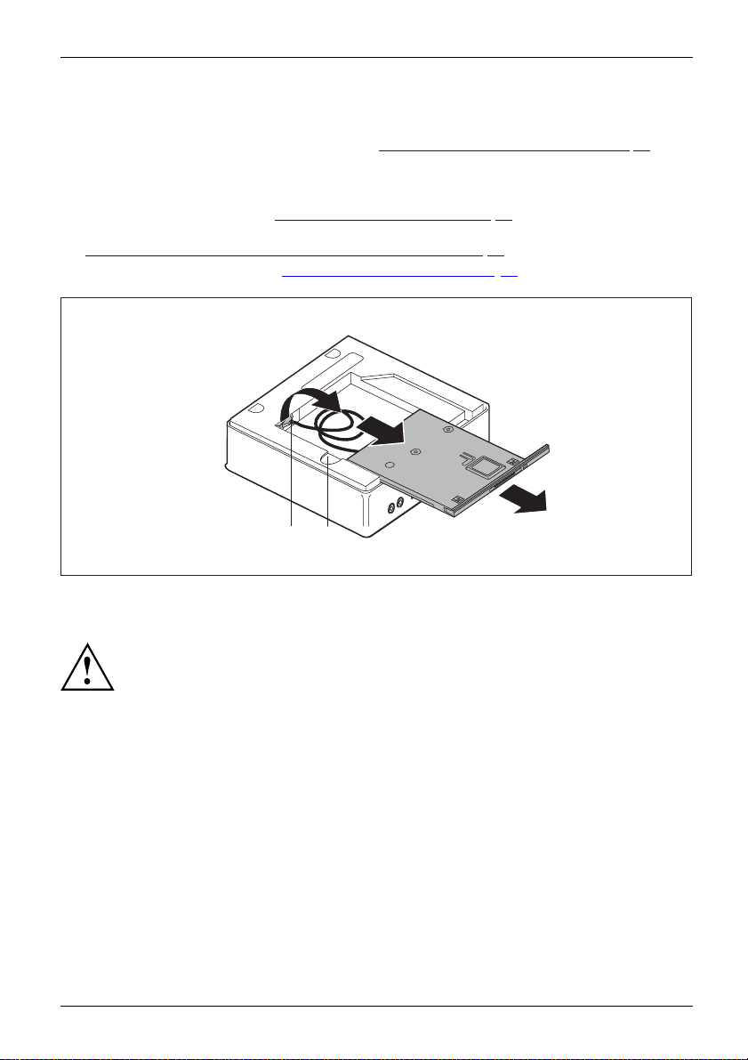
System expansions
Removing the SmartCard reader/palm sensor
• The top casing cover has been removed (see "Removing the top casing cov er", Page 63).
Removing the reader/sensor
► Remove the dri ve cage (see "Removing the drive cage", Page 65).
► Remove the reader/sensor lead from the mainboard (see graphic on slots in Section
Overview of the drive bays and drives in your device", Page 60).
"
► Reinstall the drive cage (see "
care that no cables or leads become trapped.
Installing the drive cage", Page 66). Take
2
1
3
a
b
► Press and hold the unlocking mechanism (b) and carefully push the reader/sensor slightly in the
direction of the arrow (1) until the reader/sensor and casing contacts and cables are accessible.
Ensure that you do not pull strongly on attached leads.
► Fully fee
cage (2)
► Lift the reader/sensor out of the drive bay (3).
Fujitsu 75
d the reader/sensor lead and plug (c) through the opening in the drive
out of the interior of the casing.
Page 80

System expansions
d
c
4
4
► Detach the drive plate from the drive (c) as shown (4).
► Fasten the drive plate (d) to the drive cage.
If you want to install a bla nking cover
► Install the blanking plate (see "If you want to install a blanking cover", Page 72).
If you wa nt to install an optical drive
► Insert the optical drive and associated lead (see "Installing a drive", Page 68).
76 Fujitsu
Page 81

System expansions
Removingandinstallingthe2.5
"harddisk
Removing the 2.5" hard disk
• The top c asing cover and the drive cage have been removed and the data and pow er
supply cables detached from the hard disk and mainboard (see "
casing cover", Page 63 and "Removing the drive cage", Page 65).
1
► Press the EasyChange rails mounted on the hard disk together slightly (1) and pull the
hard disk out of the drive cage in the direction of the arrow (2).
Removing the top
1
2
3
► Release the die EasyChange rails from the hard disk (3).
u do not want to remove or install any other components, replace the drive cage and
► If yo
op casing cover (see "
the t
er", Page 64). Take care that no cables or leads become trapped.
cov
Fujitsu 77
Installing the drive cage", Page 66 and "Securing the top casing
3
Page 82

System expansions
Installing a 2.5" hard disk
• The top casing cover and drive cage have been removed (see "Removing the top
casing cover", Page 63 and "Removing the drive cage", Page 65).
1
► Secure the EasyChange rails to the side of the hard disk drive (3) by inserting the pins
of the EasyChange rail into the corresponding holes in the hard disk.
1
2
► Slide the hard disk with the EasyChange rails fitted into the drive cage in the direction
of the arrow (2). Ensure that the label on the hard disk is facing upwards.
78 Fujitsu
Page 83

System expansions
► Attach the leads to the hard disk and onto the mainboard (see "Removing the drive cage",
Page 65).
You can find information on pin allocation on the mainboard in Section "Overview of the
drive ba ys and drives in your device", Page 60 and in your ma inboard manual.
► If you do not want to remove or install any other components, replace the drive cage and
the top casing cov er (see "
Installing the drive cage", Page 66 and "Securing the top casing
cover", Page 64). Take care that no cables or leads become trapped.
Fujitsu 79
Page 84

System expansions
Removing and installing the fan
You first need to remove the fan to be able to remove and install the
M.2 module and/or the lithium battery.
Removing the fan
• The top casing cover and drive cage have been removed (see "Removing the top
casing cover", Page 63 and "Removing the drive cage", Page 65).
► Disconnect the fan c ables from the mainboard.
a
1
1
a
► To release the fan attachm ent, keep the locking lugs (a) pressed in the direction of the arrow (1).
2
► Lift the fan out of the casing (2).
80 Fujitsu
Page 85

System expansions
Installing the fan
• The top casing cover and drive cage have b een removed (see "Removing the top
casing cover", Page 63 and "Removing the drive cage", Page 65).
1
► Place the fan in its installation position in the casing (1).
a
a
► Make sure that the locking lugs (a) re-engage.
► Connect the fan leads to the mainboard.
► If you do not want to remove or install any other components, replace the drive cage and
the top casing cov er (see "
cover", Page 64). Take care that no cables or leads become trapped.
Fujitsu 81
Installing the drive cage", Page 66 and "Securing the top casing
Page 86

System expansions
Inserting and removing the M.2 m
odule
Removing the M.2 module
• The top casing cover and drive cage have been removed (see "Removing the top
casing cover", Page 63 and "Removing the drive cage", Page 65).
• The fan has been removed (see "
► Undo the screw (1).
► Pull the M.2 module (b) slightly at an angle in the direction of the arrow (2) and out
of the slot (a) on th e mainboard and remove it from the casing.
► Reinstall the fan (see "
► If you do not want to remove or install any other components, replace the drive cage and
the top casing cover (see "
cover", Page 64). Take care that no cables or leads become trapped.
Installing the fan", Page 81).
Removing the fan", P age 80).
1
a
a
Installing the drive cage", Page 66 and "Securing the top casing
2
b
82 Fujitsu
Page 87

System expansions
Installing the M.2 module
• The top casing cover and drive cage have b een removed (see "Removing the top
casing cover", Page 63 and "Removing the drive cage", Page 65).
• The fan has been removed (see "
► Insert the M.2 module (b) at a slight angle in the direction of the arrow
(1) into the slot (a) on the mainboard.
► Secure the M.2 module onto the mainb oard with the screw (2).
► Reinstall the fan (see "
► If you do not want to remove or install any other components, replace the drive cage and
the top casing cov er (see "
cover", Page 64). Take care that no cables or leads become trapped.
Installing the fan", Page 81).
Removing the fan", P age 80).
2
a
1
b
a
Installing the drive cage", Page 66 and "Securing the top casing
Fujitsu 83
Page 88

System expansions
Replacing the lithium battery
In order to permanently save the system information, a lithium battery is installed to provide
the CMOS-memory with a current. A corresponding error message notifies the user when the
charge is too low or the battery is empty. The lithium battery must then be replaced.
Incorrect replacement of the lithium battery may lead to a risk of explosion!
The lithium battery may be replaced only with an identical battery or with
a type recommended by the manufacturer.
Do not dispose of lithium batteries with household waste. They must be disposed
of in accordance with l oca l regulations concerning special waste.
Make sure that you observe the correct polarity when replacing the lithium
battery. The plus pole must be on the top!
Lithiumbattery,Replacing,Replacing,Re placing,lithiumbatteryBattery
The lithium battery holder exists in different designs that function in the same way.
► Remove the top casing cover and drive cage (see "
Page 63 and "Removing the drive cage", Page 65).
► Remove the fan (see "
Removing the fan", Page 80).
Removing the top casing cover",
2
1
► Press the catch in the direction of the arrow (1).
The battery jumps out of the holder slightly.
► Remove the battery (2).
► Push the new lithium battery of the identical type into the holder (3) and
press it down until it engages.
► Reinstall the fan (see "
► If you do not want to remove or install any other components, replace the drive cage and
the top casing cover (see "
cover", Page 64). Take care that no cables or leads become trapped.
Installing the fan", Page 81).
Installing the drive cage", Page 66 and "Securing the top casing
3
84 Fujitsu
Page 89

System expansions
Removingandattachingthetopc
You need to remove the top casing cover if you want to remove or install the following components:
• Memory modules
asing cover
Removing the bottom casing cover
► Turnthedeviceover.
► If you are using a locking bracket and a padlock to protect the device, remove the lock
and open the locking bracket (see "
or
► If you are using a locking bracket and a Kensington Lock cable to protect the device,
remove the Kensington Lock cable and open the locking bracket (see "
Security Lock", Page 49 and "Using a locking bracket", Page 50).
2
Using a locking bracket", Page 50).
Using the
3
1
► Push the release on the rear side of the device in the direction of the arrow (1) while at the
same time sliding the bottom casing cover in the direction of the arrow (2).
► Lift the bottom casing cover off the device (3).
Fujitsu 85
Page 90

System expansions
Securing the bottom casing cover
1
2
► Place the bottom casing cover on the device (1).
► Slide the bottom casing cover in the direction o f the arrow (2) until it engages noticeably.
► If you are using a locking b racke t and a padlock to protect the device, close the locking
bracket and fasten the lock (see "
or
► If you are usin
close the lock
bracket", Pa
g a locking bracket and a Kensington Lock cable to protect the device,
ing bracket and fasten the Kensington Lock cable (see "
ge 50 and "Using the Security Lock", Page 49).
► Position the device the correct way up again.
Using a locking bracket", Page 50).
Using a locking
Installing and removing memory expansion
ule
emory
ansion
ansion
Memorymod
MainmemoryRemovingm
Systemexp
Systemexp
Please obs
The devic
installe
Only use m
see chap
Never u
Make su
You must open the service cover to remove or install the memory module.
The following description is identical for both memory modules.
86 Fujitsu
erve the safety information in chapter "
Important notes", Page 13.
e must not be connected to the power supply when memory modules are
d or removed, see "
Prepare to remove components", Page 62.
emory extensions that have been approved for your device,
ter "
Technical data", Page 89.
se force when installing or removing a memory extension.
re that foreign objects do not fall into the memory extension compartment.
Page 91

Open the service cover
System expansions
1
► Slide the clip in the direction of the arrow (1) and hold it there.
► Pull the cover on the tab in the direction of the arrow (2) and away from the casing.
2
Removing memory modules
3
1
1
2
► Carefully push the two mounting clips outwards (1).
MemoryexpansionMemorymodule
The memory module snaps upwards (2).
► Pull the memory module out of its slot in the direction of the arrow (3).
Fujitsu 87
Page 92

System expansions
Installing a memory module
2
1
a
► Insert the memory module with the contacts and the recess (a) facing the slot (1).
MemoryexpansionMemorymodule
► Carefully push the memory mod ule downwards until you feel it click into place (2).
Close the service cover
2
► Insert the catches of the cover in the associated recesses on the casing (2).
► Fold the cover in the direction of the arrow (2).
1
1
Finish component removal
► Connect the previously disconnecte d cables to the device again.
88 Fujitsu
Page 93

Technical data
Technical data
Electrical data
Safety standards complied with: IEC 60950-1, EN 60950-1, UL 60950-1
CSA 22.2 No.60950-1
Protection class: II
Rated voltage range 100 – 240 V
Rated frequency 50 – 60 Hz (AC)
Max. rated current 1.5 – 0.8 A
Dimensions
Width/depth/height: ESPRIMO Q 95x:
Weight
in basic configuration: approx. 1.8 kg / 4.0 lbs
Ambient conditions
Environment class 3K2
Environment class 2K2
Temperature
Operation (3K2) 15℃ to 35°C / 59°F to 95°F
Transportation (2K2) -25℃ to 60℃ / -13F to 140°F
The formation of condensation is not permitted while the device is in operation !
Clearance required to ensure adequate ventilation:
without air vents
with air vents
186 mm x 191 mm x 59 mm /
7.32” x 7.49” x 2 .30”
ESPRIMO Q55x:
185 mm x 190 mm x 54 mm /
7.28” x 7.48” x 2 .13”
DIN E N 60721-3-3
DIN E N 60721-3-2
min. 10 mm / 0.39 inch
min. 200 m m / 7.87 inches (exception: underside
in ve rtical operating position, see "
the device", Page 18)
Setting up
The data sheets of these devices contains further technical data. The data sheets
can be found on our website "
Fujitsu 89
http://www.fujitsu.com/fts/".
Page 94

Index
Index
A
Alphanumeric keypa d 39
Anti-theft protection 49
Audio output 32
B
Battery 84
BIOS Setup Utility
calling 44
exiting 45
operating 45
settings 44
Button,
ON/OFF switch 39
C
CD/DVD
emergency removal 43
Components
installing/removing 58
Configuration, BIOS Setup Utility 44
Connect
PS/2 device 34
Connect PS/2 device 34
Connecting
USB keyboard 33
Connecting a USB mouse 33
Contents of delivery 15
Ctrl+Alt+Del 40
Cursor keys 39
D
Data protection 46
Device
Ports 32
setting up 18
Switching on 37
Device drivers,
serial interface 33
Device,
switching off 37
transporting 13–14
upgrades 58
Devices,
connecting 33–34
Disposal 14
Drive cage
installing 66
removing 65
Drivers & Utilities DVD 14
E
Emergency removal, CD/DVD 43
Energy saving 14
Ergonomic
Workstation 18
External devices
Ports 32
External devices,
connecting 33–34
F
Function keys 39
G
Getting started 15
H
Handling
data carriers 41
Hardware configuration 44
I
Important notes 13
Installing,
software 35–36
switching on for the first time 35
K
Keyboard 39
Cursor keys 39
Keyboard port 32
keyboard shortcuts 40
Keyboard shortcuts 39
Keyboard,
alphanumeric keypad 39
function keys 39
numeric keypad 39
Keys 39
Ctrl 40
Ctrl+Alt+Del 40
90 Fujitsu
Page 95

Index
Keys,
Alt Gr 40
Control 40
Ctrl key 40
cursor keys 39
Enter 39
Enter key 39
menu key 40
Num Lock 40
Return 39
shift 40
shift key 40
Start key 40
L
LAN port 32
Lead-sealing 52
Lead-sealing chain 52
Lead-sealing wire 52
Line out 32
Lithium battery,
replacing 84
Locking bracket 51
M
Main memory
see Adding memory 86
Mechanical safeguard
Kensington Lock cable 49
Lead-sealing 52
Locking bracket 51
Padlock clamp 51
Security lock 49
Memory expansion
installing 88
removing 87
Memory module
important notes 86
installing 88
removing 87
Monitor
connecting 33
Switching on 37
Monitor port
DVI-D 32
Monitor,
switching off 37
N
Note
safety 13
Notes
important 13
Numeric keypad 39
O
ON/OFF switch 39
Optical drive 41
Overview
Device 7
P
Packaging 15
Packaging,
unpacking 15
Padlock clamp 51
Password protection 46
Ports 9, 32
Power cable
connection 30
Preparing for first use, overview 15
Preparing for operation 30
Preparing for use,
overview 15
Property protection 46
R
Recycling 14
Removing by hand, CD/D VD 43
Removing memory
see Adding memory 86
Replacing,
lithium battery 84
Replacing, lithium battery 84
Retransportation 13–14
S
Safety information 13
Security functions
SystemLock 46
Security functions,
SmartCard 46
Security Lock 49
Security measures 46
Serial interface 32–33
Serial interface,
connecting devices 33
settings 33
Servicing 58
Setup
see BIOS Setup Utility 44
Software,
installing 35–36
Fujitsu 91
Page 96

Index
System configuration 44
System expansion 58, 86
see Adding memory 86
System settings, BIOS Setup Utility 44
System unit, see Device 14
T
Transportation 13–14
U
Universal Serial Bus 32
Upgrades,
device 58
USB devices,
connecting 34
USB port 33
connecting keybo a rd 33
USB port,
connecting devices 34
User Documentation DVD 14
Using th e Kensington Lock Cable 49
W
Workstation 18
92 Fujitsu
 Loading...