

Page 1

CA92344-1879-04
FUJITSU PSWITCH 2048T
FUJITSU PSWITCH 2048P
FUJITSU PSWITCH 4032P
User’s Guide
Network Management
December 2018
Page 2

FUJITSU PSWITCH User’s Guide
2 December/2018
Copyright and Trademarks
Copyright 2018 FUJITSU LIMITED All rights reserved.
Delivery subject to availability; right of technical modifications reserved.
All hardware and software names used are trademarks of their respective
manufacturers.
– The contents of this manual may be revised without prior notice.
– Fujitsu assumes no liability for damages to third party copyrights or other rights
arising from the use of any information in this manual.
– No part of this manual may be reproduced in any form without the prior written
permission of Fujitsu.
Microsoft, Windows, Windows Server, and Hyper V are trademarks or registered
trademarks of Microsoft Corporation in the USA and other countries.
Intel and Xeon are trademarks or registered trademarks of Intel Corporation or its
subsidiaries in the USA and other countries.
Page 3

User’s Guide FUJITSU PSWITCH
December/2018 3
1. High Risk Activity
The Customer acknowledges and agrees that the Product is designed, developed
and manufactured as contemplated for general use, including without limitation,
general office use, personal use, household use, and ordinary industrial use, but is
not designed, developed and manufactured as contemplated for use
accompanying fatal risks or dangers that, unless extremely high safety is secured,
could lead directly to death, personal injury, severe physical damage or other loss
(hereinafter "High Safety Required Use"), including without limitation, nuclear
reaction control in nuclear facility, aircraft flight control, air traffic control, mass
transport control, medical life support system, missile launch control in weapon
system.
The Customer, shall not use the Product without securing the sufficient safety
required for the High Safety Required Use. In addition, Fujitsu (or other affiliate's
name) shall not be liable against the Customer and/or any third party for any
claims or damages arising in connection with the High Safety Required Use of the
Product.
Collecting and Recycling used products
We collect and recycle our products which discharged from our corporate customer
for a fee.
For collecting and recycling of this product, refer to the following Fujitsu website.
URL:
http://www.fujitsu.com/global/about/environment/society/recycleinfo/index.html
Page 4

FUJITSU PSWITCH User’s Guide
4 December/2018
Contents
1 Product Overview 6
1.1. Front View .................................................................................................6
1.2. Rear View ..................................................................................................7
1.3. LED Identification .....................................................................................8
1.3.1. Front LEDs .....................................................................................................8
1.3.2. Rear LEDs ....................................................................................................11
1.4. System Specification ...............................................................................12
2 Getting Started with Configuration 14
2.1. Mounting.................................................................................................14
2.1.1. Rack Mounting ............................................................................................14
2.1.2. Attachment of Power Supply Unit ................................................................19
2.1.3. Inserting of SFP modules .............................................................................19
2.1.4. Connection to a Power Source ......................................................................20
2.1.5. Startup confirmation ...................................................................................21
2.2. Connecting to the Console of the Switch ................................................22
2.3. Accessing Management Port ..................................................................23
2.4. Initial Configuration of the switch .........................................................24
2.4.1. Checking version and system information ...................................................24
2.4.2. Setting the System Clock of the Switch .........................................................24
2.4.3. Enabling/Disabling Posts .............................................................................25
2.4.4. 1G SFP module ............................................................................................26
2.4.5. Firmware Update .........................................................................................26
2.4.6. Backup and Restore Configuration ...............................................................27
2.5. System Logging .......................................................................................27
2.6. How to collect diagnostic information ...................................................29
2.7. POST Control............................................................................................29
3 Software Feature 31
3.1. Functional Overview ...............................................................................31
3.1.1. Switch Management ....................................................................................31
3.1.2. Layer 2 Switching ........................................................................................50
3.1.3. Multicast .....................................................................................................90
3.1.4. DHCP (Dynamic Host Configuration Protocol) ..............................................98
3.1.5. Security & AAA ........................................................................................... 101
3.1.6. System Utility ............................................................................................ 109
Page 5

User’s Guide FUJITSU PSWITCH
December/2018 5
3.1.7. QoS (Quality of Service) ............................................................................. 112
3.1.8. Data Center and Virtualization ................................................................... 113
3.1.9. Layer 3 Servise .......................................................................................... 119
3.2. Operation Samples ............................................................................... 143
3.2.1. VLAN setting .............................................................................................. 143
3.2.2. Link aggregation ....................................................................................... 144
3.2.3. VPC ............................................................................................................ 145
3.2.4. Packet Filtering Function ........................................................................... 146
3.2.5. STP ............................................................................................................ 146
3.2.6. Port mirroring ............................................................................................ 147
3.2.7. LLDP function ............................................................................................ 147
3.2.8. SNMP agent function ................................................................................. 147
3.2.9. EHM .......................................................................................................... 148
3.2.10. LDAP ....................................................................................................... 148
3.3. Switch Parameters ................................................................................ 149
3.4. Software Feature List ............................................................................ 151
3.5. Software Feature Combination Matrix ................................................. 153
3.6. Management Information Base (MIB) ................................................. 155
4 Maintenance 157
4.1. Preparation ........................................................................................... 157
4.2. How to Replace the Switch (FRU: Field-Replaceable Unit※) .............. 158
4.3. How to Replace FAN Unit ...................................................................... 166
4.4. How to Replace Power Unit(CRU: Customer Replaceable Unit※) ........ 167
4.5. Battery Power ....................................................................................... 169
4.6. How to Replace Battery (FRU: Field-Replaceable Unit※) ................... 170
4.7. Transitions of Device Temperature ....................................................... 176
5 Product Specification 178
6 Hardware Specification 179
7 Externally Licensed Components 183
Page 6

FUJITSU PSWITCH User’s Guide
6 December/2018
1 Product Overview
The FUJITSU PSWITCH has three different models depending on their port type. The
FUJITSU PSWITCH 2048T is a model with forty-eight 10GbE BASE-T ports and six
40GbE QSFP ports. The FUJITSU PSWITCH 2048P is a model with forty-eight 10GbE
SFP+ ports and six 40GbE QSFP ports. The FUJITSU PSWITCH 4032P is a model with
thirty-two 40GbE QSFP ports.
1.1. Front View
FUJITSU PSWITCH 2048T
Figure 1-1: Front View (FUJITSU PSWITCH 2048T)
FUJITSU PSWITCH 2048P
Figure 1-2: Front View (FUJITSU PSWITCH 2048P)
Page 7
User’s Guide FUJITSU PSWITCH
December/2018 7
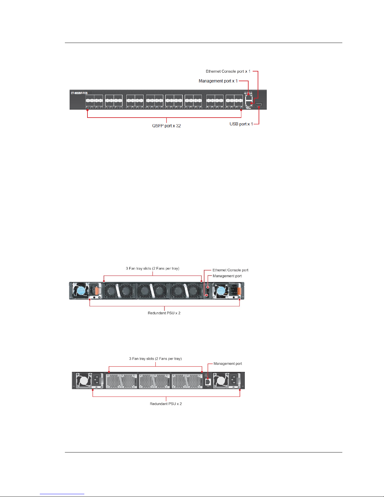
FUJITSU PSWITCH 4032P
Figure 1-3: Front View (FUJITSU PSWITCH 4032P)
The micro USB console port and the reset button on the front side of
FUJITSU PSWITCH 2048T are not intended to be used by customer. Please
do not use those interfaces. In FUJITSU PSWITCH 2048T, a seal which is the
same color(black) as the main body of the switch is pasted to cover those
ports.
1.2. Rear View
FUJITSU PSWITCH 2048T
Figure 1-4: Rear View (FUJITSU PSWITCH 2048T)
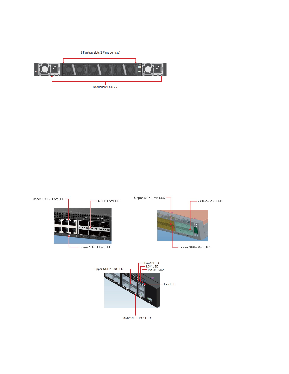
FUJITSU PSWITCH 2048P
Figure 1-5: Rear View (FUJITSU PSWITCH 2048P)
V
Page 8
FUJITSU PSWITCH User’s Guide
8 December/2018
FUJITSU PSWITCH 2048P
Figure 1-6: Rear View (FUJITSU PSWITCH 4032P)
The two power supply units mounted on this switch are designed to provide
1+1 redundancy, and hot-pluggable. The three fan trays (2 fans per tray) on
the rear side are not redundant and not hot-pluggable.
1.3. LED Identification
1.3.1. Front LEDs
Figure 1-7: Front LED Identification (Top Left: FUJITSU PSWITCH 2048T, Top Right: FUJITSU
PSWITCH 2048P, Bottom: FUJITSU PSWITCH 4032P)
I
Page 9

User’s Guide FUJITSU PSWITCH
December/2018 9
FUJITSU PSWITCH 2048T/P
LED
LED status
Condition
System LED
Off
Power is off
Solid Green
Normal operation
Blinking Green
Booting in progress
Solid Yellow
Major faults, the faults are traffic affecting
Blinking Yellow
Minor faults, the faults are not traffic affecting
Power LED
Off
Power is disconnected
Solid Green
Operating normally (Dual or Single Supply)
Solid Yellow
POST in progress
Blinking Yellow
One of Power Supplier is failed
Fan LED
Solid Green
FAN operating normally
Solid yellow
FAN is failed including incompatible airflow direction
Located LED
Off
No power or the locator function is disabled.
Blinking Blue
The locator function is enabled
10Gbase-T
Port LEDs
Off
No link (Link LED)
Solid Green
A valid 10Gbps link (Link LED)
Solid Yellow
A valid 1Gbps link (Link LED)
Blinking Green
Packet transmission or reception in progress (ACT LED)
10G SFP+ slot
LEDs
Off
No link (Link LED)
Solid Green
A valid 10Gbps link (Link LED)
Solid Yellow
A valid 1Gbps link (Link LED)
Blinking Green
Packet transmission or reception in progress (ACT LED)
40G QSFP slot
LEDs
Off
No link (Link LED)
Solid Green
A valid 40Gbps link (Link LED)
Solid Amber
A valid 10Gbps link (Link LED)
Blinking Green
40G speed, Packet transmission or reception in progress
(ACT LED)
Blinking Amber
10G speed, Packet transmission or reception in progress
(ACT LED)
Table 1-1: Front LED status (FUJITSU PSWITCH 2048T/P)
Page 10

FUJITSU PSWITCH User’s Guide
10 December/2018
FUJITSU PSWITCH 4032P
LED
LED status
Condition
System LED
Off
Power is off
Solid Green
Normal operation
Blinking Green
Booting in progress
Solid Yellow
Major faults, the faults are traffic affecting
Blinking Yellow
Minor faults, the faults are not traffic affecting
Power LED
Off
Power is disconnected
Solid Green
Operating normally (Dual or Single Supply)
Solid Yellow
POST in progress
Blinking Yellow
One of Power Supplier is failed
Fan LED
Solid Green
FAN operating normally
Solid yellow
FAN is failed including incompatible airflow direction
Located LED
Off
No power or the locator function is disabled.
Blinking Blue
The locator function is enabled
40G QSFP slot
LEDs
Off
No link (Link LED)
Solid Green
A valid 10G/40Gbps link (Link LED)
Blinking Green
10G/40G speed, Packet transmission or reception in
progress (ACT LED)
Management
Port LEDs
Off
No link is established on the port
Solid Yellow
A valid link at 10/100Mbps is established on the port
(Link LED)
Solid Green
A valid link at 1000Mbps is established on the port
(Link LED)
Blinking Green
Activity, transmitting or receiving packet at this port
(ACT LED)
Table 1-2: Front LED status (FUJITSU PSWITCH 4032P)
FAN LED on the front panel will be yellow when one of the FAN LEDs at the
rear side fails.
I
Page 11

User’s Guide FUJITSU PSWITCH
December/2018 11
1.3.2. Rear LEDs
Figure 1-8: Rear LED Identification of Fan Tray and Power Supply
FUJITSU PSWITCH 2048T/P
LED
LED Status
Condition
Fan tray LED
Solid Green
Fan powered on at expected rotates per minute
Solid Yellow
Fan failure
Power Supply
LED
Off
No power
Solid Green
Power is ok
Solid Yellow
Power supply critical event causing a shutdown; failure
Blinking Yellow
Power supply warning events where the power supply
continues to operate
Management
Port LEDs
Off
No link is established on the port
Solid Yellow
A valid link at 10/100Mbps is established on the port
(Link LED)
Solid Green
A valid link at 1000Mbps is established on the port
(Link LED)
Blinking Green
Activity, transmitting or receiving packet at this port
(ACT LED)
Table 1-3: Rear LED status (FUJITSU PSWITCH 2048T/P)
Page 12

FUJITSU PSWITCH User’s Guide
12 December/2018
FUJITSU PSWITCH 4032P
LED
LED Status
Condition
Fan tray LED
Solid Green
Fan powered on at expected rotates per minute
Solid Yellow
Fan failure
Power Supply
LED
Off
No power
Solid Green
Power is ok
Solid Yellow
Power supply critical event causing a shutdown; failure
Blinking Yellow
Power supply warning events where the power supply
continues to operate
Table 1-4: Rear LED status (FUJITSU PSWITCH 4032P)
1.4. System Specification
System Specification
Component
Specification
Switch fabric capacity
[FUJITSU PSWITCH 2048T/P]
Non-blocking full wire speed on all packet sizes
[FUJITSU PSWITCH 4032P]
1,428 Mpps
Forwarding architecture
Store and forward or cut-through
Port packet forwarding rate
(at 64 Bytes)
59,523,809 pps (40GbE).
14,880,952 pps (10GbE).
MAC address entries
supported
96K entries.
1,000,000 seconds programable.
Default 300 seconds.
Spanning Tree Support
Support IEEE802.1d STP.
Support IEEE802.1s MSTP.
Support IEEE802.1w RSTP.
Storm Control
Rate control based on packet / byte.
Unknown unicast (DLF) packet.
Broadcast packet.
Known & unknown L2MC packets.
Known & unknown IPMC packets.
Enable individual threshold per port.
Memory type
12 MBytes buffer memory
Page 13

User’s Guide FUJITSU PSWITCH
December/2018 13
OOB port
10/100/1000Mbps, auto sensing, auto negotiation
Console port
Serial RS232 console port (RJ45)
Serial console
Provide visual feedback of the boot process to the user.
Timeout after period of inactivity.
Table 1-5: System Specification
Port Specification
FUJITSU PSWITCH 2048T/P
Component
Specification
Speed Capability
1G/10Gbps or 10/40Gbps
Full-Duplex Flow Control
Support the IEEE 802.3x PAUSE frame
Table 1-6: Port Specifications (FUJITSU PSWITCH 2048T/P)
FUJITSU PSWITCH 4032P
Component
Specification
Speed Capability
10/40Gbps
Full-Duplex Flow Control
Support the IEEE 802.3x PAUSE frame
Table 1-7: Port Specifications (FUJITSU PSWITCH 4032P)
Page 14

FUJITSU PSWITCH User’s Guide
14 December/2018
2 Getting Started with Configuration
2.1. Mounting
Install this unit in a standard 19-inch rack. Install from the back of the rack. Follow
the procedure below to install the equipment.
When carrying out maintenance support by our technical experts, prepare
with reference to the contents of Chapter 4 "Maintenance" - "4.1.
Preparation".
2.1.1. Rack Mounting
Please pay attention to the following points before installation work.
Do not place another device on the rack mounted device.
Be careful not to exceed the limit of the power supply of rackmounted
equipment.
Be careful to ensure that the rack mounted equipment is properly insulated.
2.1.1.1. Installation of L-shaped brackets and rack rails
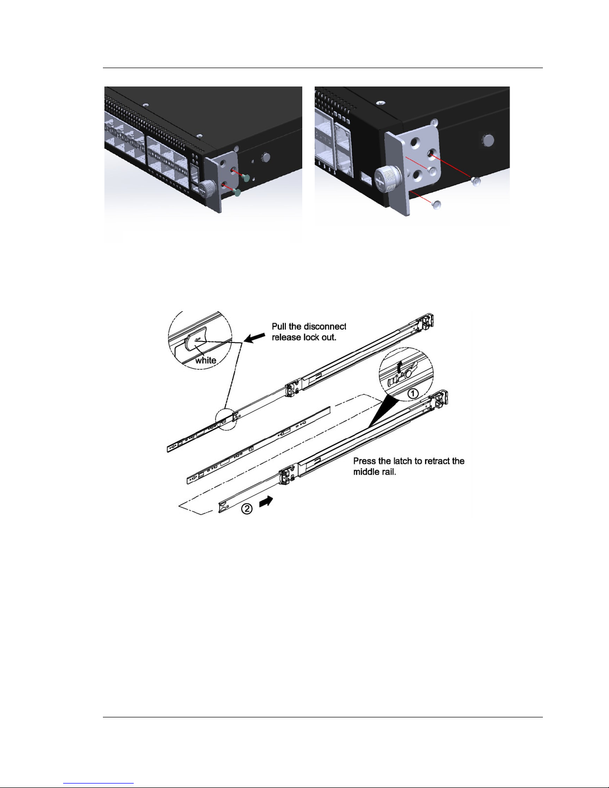
Attach the L-shaped brackets to the front of the server as shown in the figure below.
Please attach so that the L shape brackets with model name and number label
attached is on the left side of the front side of the equipment. For each L-shaped
bracket, attach it by using 2 screws for PSWITCH 2048T/P and 3 screws for PSWITCH
4032P. Release and detach the inner member from the slide. Attach the inner
member to the unit.
I
Page 15
User’s Guide FUJITSU PSWITCH
December/2018 15
Figure 2-1: Attachment of L-shaped bracket
Figure 2-2: Withdrawing the inner rail
FUJITSU PSWITCH 2048T/P
FUJITSU PSWITCH 4032P
Page 16
FUJITSU PSWITCH User’s Guide
16 December/2018
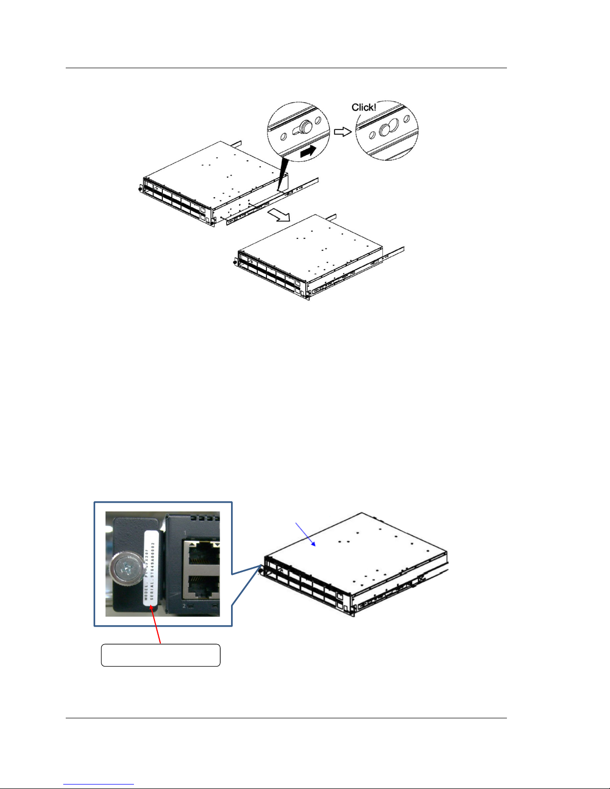
Figure 2-3: Attachment of rack rail
2.1.1.2. Rack Mounting
Insert this device from the rear side of the rack.
You can see the unit label on the L-shaped bracket from the rear side of
the rack.
Figure 2-4: Label
MODEL. PY-SWX48T
SERIAL. MAGU******
Label : on which the model name and the serial number are written.
PSWITCH
V
V
Page 17
User’s Guide FUJITSU PSWITCH
December/2018 17
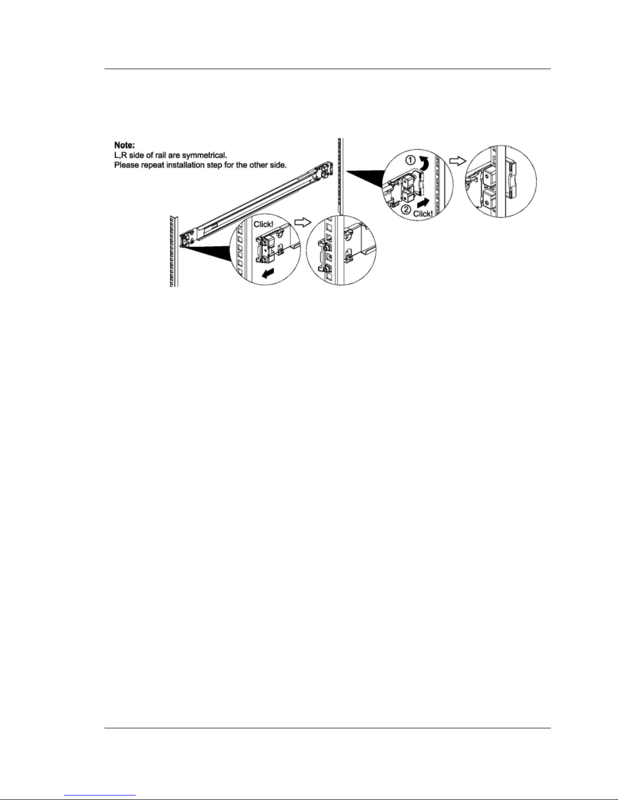
1. Attach the outer rail of the rack rail to the rack.
Figure 2-5: Attachment of outer rail to the rack
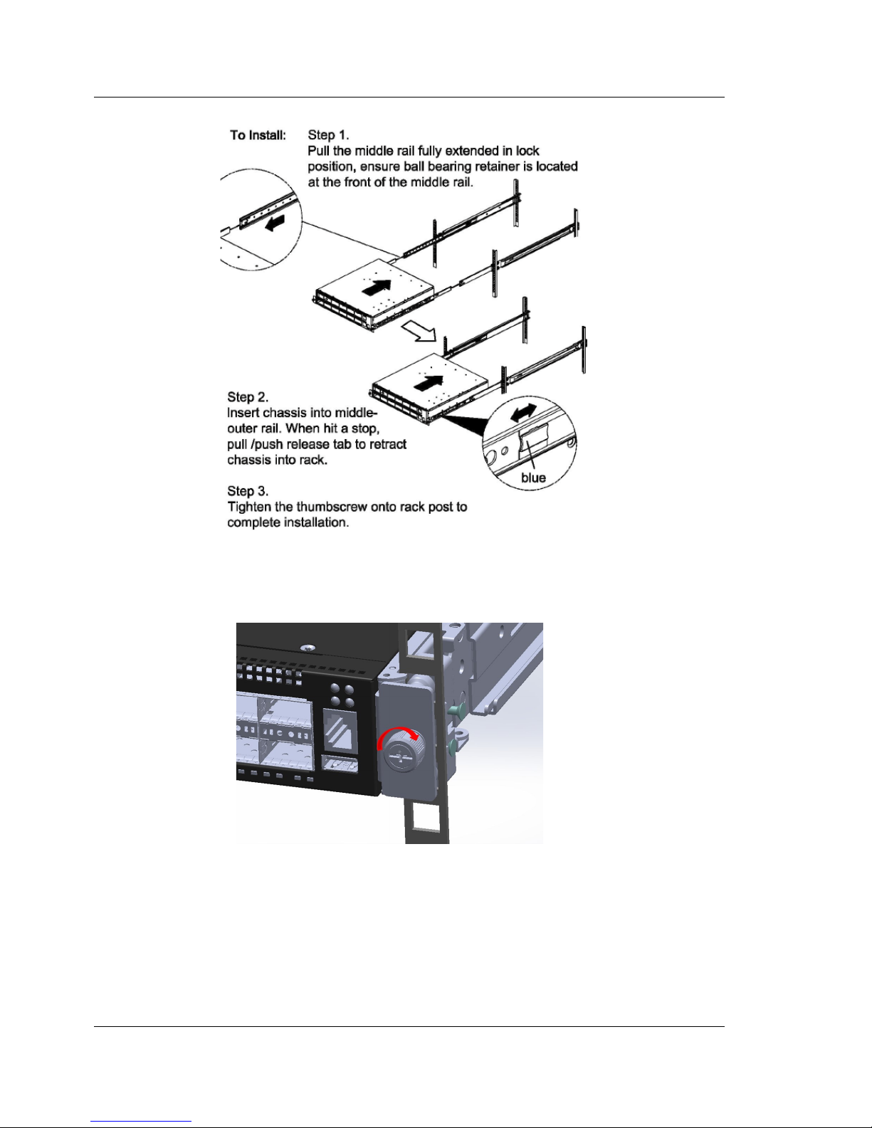
2. Insert the unit onto the rack.
To reduce the weight of the device, remove the both power supply units
form the device.
Then, insert the inner rail into the outer rail and mount the device in the rack.
V
Page 18
FUJITSU PSWITCH User’s Guide
18 December/2018
Figure 2-6: Insert the device onto the rack
Fix the bracket assembly to the frame.
Figure 2-7: Fix the bracket to the frame
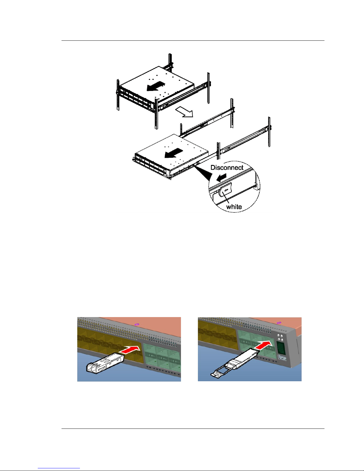
When removing the equipment from the rail, please refer to the figure below.
Page 19
User’s Guide FUJITSU PSWITCH
December/2018 19
Figure 2-8: Unmount device from rack
2.1.2. Attachment of Power Supply Unit
Please insert the both two power supply units(PSUs).
2.1.3. Inserting of SFP modules
Install the modules required for SFP+ slot and QSFP slot.
Figure 2-9: Inserting a SFP+/QSFP module into a slot
Inserting a SFP+ module
Inserting a QSFP module
Page 20
FUJITSU PSWITCH User’s Guide
20 December/2018
Please install SFP+/QSFP modules according to the following procedure.
1. Select the appropriate SFP+/QSFP module according to your requirements.
2. Refer to the above figure and insert the module so that the connector face
faces down.
3. Insert the module tightly until it is fixed.
SFP+/QSFP modules can be hot swapped. It is not necessary to turn off the
unit when inserting or removing a module. However, when inserting or
removing a module, unplug the network cable from the module
beforehand.
SFP+/QSFP modules are not included with the switch.
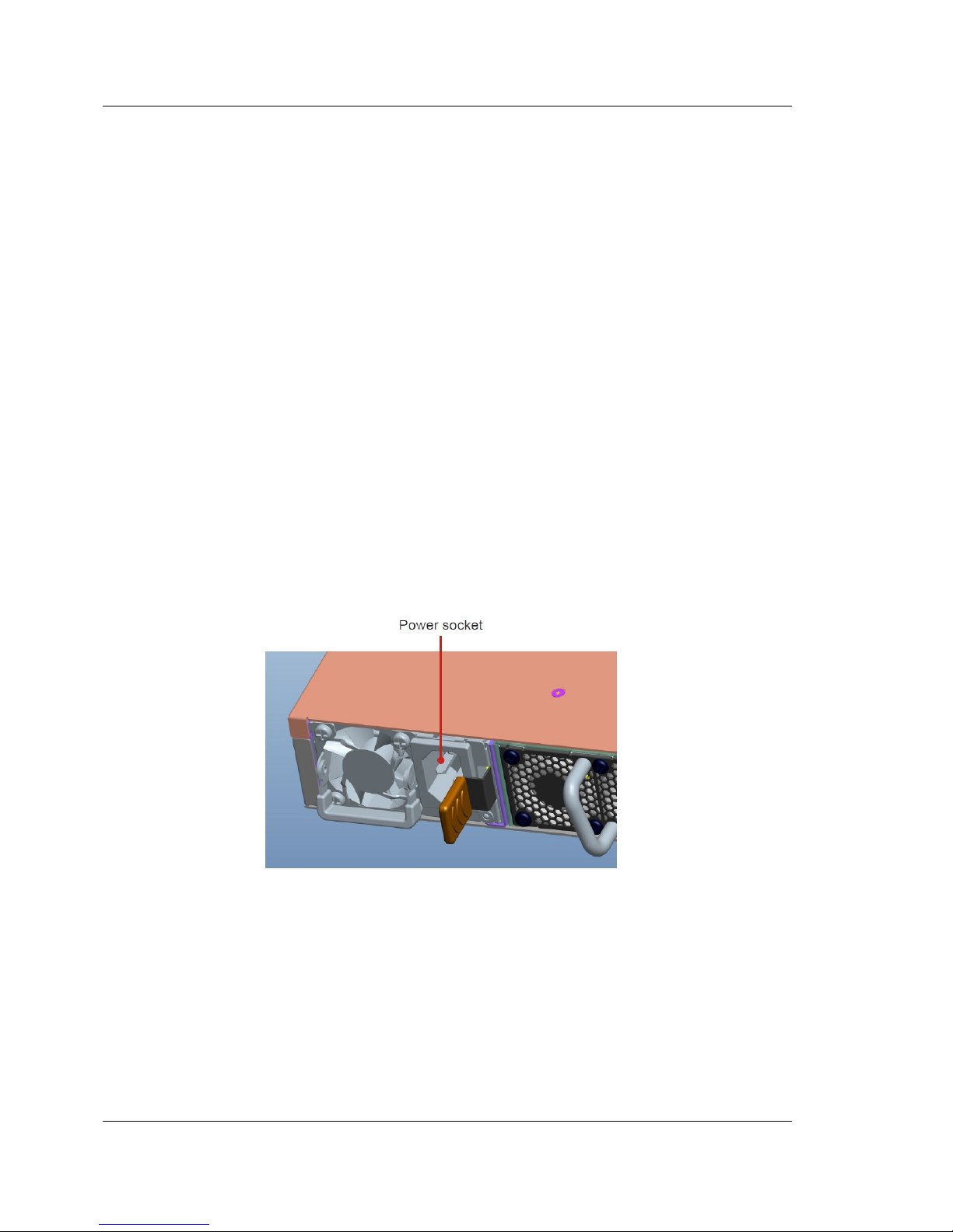
2.1.4. Connection to a Power Source
Plug the power cable’s plug into the power socket of the PSU. Plug the other end of
the cable into a grounded, 3-pin, AC power source. In the same way, connect the
other power cable into the other PSU.
Figure 2-10: Power Supply Unit
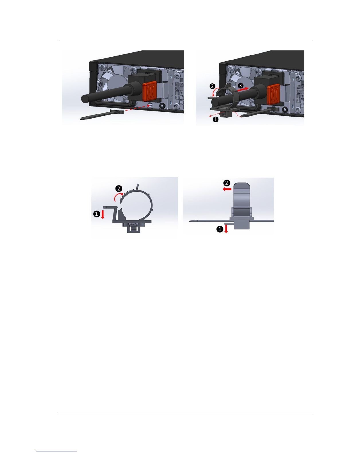
Lock the power cable as shown below.
I
I
Page 21
User’s Guide FUJITSU PSWITCH
December/2018 21
Figure 2-11: Installation of the power cable locker
Please refer to the figure below when removing the power cable locker.
Figure 2-12: How to unlock locker of Power Cable
2.1.5. Startup confirmation
First, confirm that the device started up correctly in the state of the LED of the main
unit. Make sure the SYSTEM LED, POWER LED, and FAN LED on the front of the
main unit are lit in green.
Next, connect the console to check the status of the firmware. Follow the
instructions for connecting to the switch console in the next chapter and log in to
the system with user 'admin'. You can check the version number of the current
Runtime (firmware) with the show version command. Please refer to the article
"2.4.1. Checking version and system information".
Check the firmware version number and update it if it is different from the
expected version number. Firmware update is done using FTP/TFTP server. Follow
the steps below to update the firmware.
1. Installation of fixing band
2. Installation of fixing clamp
Page 22

FUJITSU PSWITCH User’s Guide
22 December/2018
1. Configure the management port. Refer to the explanation of "2.2. Connecting
to the Console of the Switch".
2. Update the firmware using the copy command.
2.2. Connecting to the Console of the Switch
According to the following steps, you can access the console of the switch.
1. Turn on AC power of the switch to start up. It takes about 10 minutes for the
switch to be booted up.
2. Connect the switch to a console device.
Use the Ethernet console port of the switch for the connection. The
RJ-45-to-DB-9 cable supplied with the switch is available for connecting to
RS-232 serial port of a device.
3. Configure the terminal with the following settings.
Items
Value
Baud Rate
115200
Data Bit
8
Parity
none
Stop Bit
1
Flow Control
none
4. Login to the system with user admin. There is no default password.
Initially the switch does not have IP address. However, the DHCP client on the
management port is enabled by default. IP address and other network properties
are automatically assigned by DHCP. You can configure the management port
manually in the following way.
5. Check the current settings with show serviceport command.
#show serviceport
Interface Status............................... Up
IP Address..................................... 192.168.133.226
Subnet Mask.................................... 255.255.255.0
Default Gateway................................ 192.168.133.2
IPv6 Administrative Mode....................... Enabled
IPv6 Prefix is ................................ fe80::230:abff:fef4:ca6b/64
Configured IPv4 Protocol....................... DHCP
Configured IPv6 Protocol....................... None
IPv6 AutoConfig Mode........................... Disabled
Burned In MAC Address.......................... 00:30:AB:F4:CA:6B
Page 23

User’s Guide FUJITSU PSWITCH
December/2018 23
6. Disable DHCP and assign IPv4 address with serviceport command.
#serviceport protocol none
#serviceport ip <ipaddress> <netmask> [<gateway>]
In the same way, when you assign IPv6 address, use the following commands.
#serviceport protocol none
#serviceport ipv6 address <address>/<prefix-length> [eui64]
#serviceport ipv6 gateway <gateway-address>
For enabling DHCP again, enter the following command.
#serviceport protocol dhcp
If you plan to access the management port through telnet protocol, enable the
telnet with the following command, since it is disabled by default.
#ip telnet server enable
On the other hand, SSH protocol is enabled by default. It is not needed to enable
SSH at this point. For future reference, following is a set of commands to enable
SSH access.
#configure
(Config)# crypto key generate dsa
(Config)# crypto key generate rsa
(Config)# exit
#ip ssh server enable
New user account is added with the following command.
#configure
(Config)#username <username> password <password> level <privilege-level>
Finally, if you make your settings persistent, enter the following command and
save the on-memory configuration into the switch storage. This command asks you
confirmation. Press ‘y’, if you really save the configuration.
# copy system:running-config nvram:startup-config
2.3. Accessing Management Port
The management port is the dedicated port for the remote switch management.
Using the IP address assigned to the management port, you can access the switch
remotely. Telnet, SSH, SNMP, or other network management interfaces are
available with the management port.
Page 24

FUJITSU PSWITCH User’s Guide
24 December/2018
2.4. Initial Configuration of the switch
You can set up the switch in the CLI through the console or the management port
of the switch.
2.4.1. Checking version and system information
You can check the current runtime version with the show version command.
#show version
Current Runtime Version........................ 1.0.0
Current Runtime Build Time..................... Fri Jan 20 14:11:24 CST 2017
First Runtime Version.......................... 1.0.0
First Runtime Build Time....................... Fri Jan 20 14:11:24 CST 2017
Second Runtime Version......................... 1.0.0
Second Runtime Build Time...................... Fri Jan 20 14:11:24 CST 2017
Diagnostic Program Version..................... 0.1.3
ONIE Version................................... 1.0.0
Bootloader Version............................. 1.0.0
You can check the current system information with the show sysinfo command.
#show sysinfo
System Description............................. Fujitsu ET-7648BRA-FOS, 0.1.17, Linux 3.5.7+
System Name.................................... ET-7648BRA-FOS
System Location................................
System Contact.................................
System Object ID............................... 1.3.6.1.4.1.4413
System Up Time................................. 0 days 4 hrs 12 mins 40 secs
Current SNTP Synchronized Time................. SNTP Client Mode Is Disabled
2.4.2. Setting the System Clock of the Switch
The time stamp is recoded in the system logs and other system resources based on
the system clock to indicate when a certain event takes place. Setting correct time
stamp is important for maintenance and support. There are two ways to set up the
time stamp – You can simply set up the clock manually, or if you have a SNTP
(Simple Network Time Protocol) server, you can setup the system clock
synchronizing with your SNTP server.
If you set up the system clock manually, a set of time zone commands are used.
The following example set up the system time, 3:02 PM and the date, January 30,
2017 with the clock set command, and then set the time zone, UTC +9 hours and
the zone name Japan Standard Time (JST), with the clock timezone command.
#configure
(Config)# clock timezone +9 zone JST
Page 25

User’s Guide FUJITSU PSWITCH
December/2018 25
(Config)# clock set 15:02:00
(Config)# clock set 01/30/2017
You can check the result of the setting with the show clock command.
#show clock detail
15:02:05 JST(UTC+9:00) Jan 30 2017
No time source
Time zone:
Acronym is JST
Offset is UTC+9:00
Summertime:
Summer time is disabled
If you set up the system clock to synchronize with a SNTP server, use the sntp
server command to specify the location of the server as in the example below.
After setting up the timezone, you enable the SNTP client on the switch in unicast
mode.
#configure
(Config)#sntp server time-a.nist.gov
(Config)#clock timezone +9
(Config)#sntp client mode unicast
You can check the result of the setting with the show sntp command and the
show clock command.
(Routing) #show sntp
Last Update Time: Jan 30 07:42:23 2017
Last Unicast Attempt Time: Jan 30 07:43:28 2017
Last Attempt Status: Success
(Routing) #show clock
16:47:22 (UTC+9:00) Jan 30 2017
Time source is SNTP
2.4.3. Enabling/Disabling Posts
In the initial state, all the network ports of the switch are enabled. To disable the
ports, use “shutdown” command. In the following example, ports 0/1-0/2
are disabled.
#configure
(Config)#interface 0/1-0/2
(Interface 0/1-0/2)#shutdown
(Interface 0/1-0/2)#exit
All the ports are disabled at once by using the following command.
#configure
(Config)#shutdown all
(Config)#exit
Page 26

FUJITSU PSWITCH User’s Guide
26 December/2018
To enable the ports again, use “no shutdown” command. In the following example,
ports 0/1-0/2 are enabled.
#configure
(Config)#interface 0/1-0/2
(Interface 0/1-0/2)#no shutdown
(Interface 0/1-0/2)#exit
In the same way, all the ports are enabled at once by using the following
command.
#configure
(Config)#no shutdown all
(Config)#exit
2.4.4. 1G SFP module
When 1G SFP module is used in a 10G SFP+ port it is needed to specify the port
speed manually, since the port is 10G fixed speed by default. Following is an
example to setup 1G port speed for the port 0/1 and 0/2.
#configure
(Config)#interface 0/1-0/2
(Interface 0/1-0/2)#speed auto 1000
(Interface 0/1-0/2)#exit
(Config)#exit
2.4.5. Firmware Update
In order to download the firmware image into the switch, a TFTP server is necessary
outside of the switch. In the following example, assume that IP address of the TFTP
server is 192.168.1.10, and the name of the firmware image is ‘fjtor-runtime’.
Before start updating firmware, the TFTP server must be correctly configured and
the communication between the TFTP server and the switch must be established.
As in the following example, download the firmware image from the TFTP server by
copy command, and then reboot the system.
# copy tftp://192.168.1.10/fjtor-runtime system:all-runtime
# reboot runtime
For details on the copy command, refer to “CLI Command Reference” – “8.System
Utility Commands” – “8.8.System Utility and Clear Commands” – “8.8.11.copy”.
The configuration of the switch stored in the storage of the switch is maintained
even after firmware update. After the firmware update, you can check the
firmware’s version with ‘show version’ command.
Page 27

User’s Guide FUJITSU PSWITCH
December/2018 27
2.4.6. Backup and Restore Configuration
The backup and restoration of the switch configuration is done with the copy
command. This switch firmware has a capability to maintain three configurations
in the permanent storage. The names of the three configurations are the
‘first-config’, ‘second-config’, and ‘third-config’. The configuration copied to the
‘startup-config’ becomes effective after reboot.
If you back up the current configuration to a server, use the copy command as in
the following example. The current -- startup-config, is copied to the file named
‘startup-config.backup’ in the server with IP address 192.168.1.10.
#copy nvram:startup-config tftp://192.168.1.10/startup-config.bkup
In the same way, you back up the second configuration with the following
command.
#copy nvram:second-config tftp://192.168.1.10/second-config.bkup
The restoration of the configuration file is a reverse operation of the backup. If you
restore the ‘startup-config.bkup’ file above into the switch, use the following
command, and reload the configuration or reboot the switch.
#copy tftp://192.168.1.10/startup-config.bkup nvram:startup-config
#reload configuration
The configuration file is checked at the download to the switch, and if it contains
any format or command error, it would not be saved in the configuration.
2.5. System Logging
The following command displays the current configuration of the logging.
#show logging
Logging Client Local Port : 514
Logging Client Source Interface : (not configured)
CLI Command Logging : enabled
Console Logging : enabled
Console Logging Severity Filter : error
Buffered Logging : enabled
Buffered Logging Severity Filter : info
Persistent Logging : enabled
Persistent Logging Severity Filter : info
Syslog Logging : enabled
Log Messages Received : 195
Log Messages Dropped : 0
Log Messages Relayed : 0
Page 28

FUJITSU PSWITCH User’s Guide
28 December/2018
In this switch, console logging, buffered logging and persistent logging are
enabled by default. If an event occurs, depending on its severity, some
correspondent system log entry is displayed on your console and recoded into a
buffer on memory. The entries saved in the buffer will be flashed over power-off/on
or reboot of the switch. The persistent logging function saves the logs in the
storage of the switch. So, it makes possible that the logs can be kept even over
power off/on or reboot of the switch.
The persistent logging is disabled by the following command.
#configure
(Config)#no logging persistent
To enable persistent logging again, use the following command. The parameter is
the level of the logging severity.
#configure
(Config)#logging persistent ?
<severitylevel> Enter Logging Severity Level (emergency|0, alert|1,
critical|2, error|3, warning|4, notice|5, info|6,
debug|7).
(Config)#logging persistent 6
In addition, you can also save the system log into a remote host. In this case,
system logging is needed to be enabled. And a logging host is needed to be
configured for logging and registered to the switch. For the setting, see “FUJITSU
PSWITCH CLI Command Reference” – “8. System Utility Commands” – “8.13. Logging
Commands” – “8.13.9. logging host”.
If you want to include all the CLI operations on the switch, enable CLI logging with
the following command.
#configure
(Config)#logging cli-command
The following command displays the system log entries in the buffer.
#show logging buffered
The following command displays the system log entries on the switch storage if the
persistent logging is enabled.
#show logging persistent
You can send the system log out of the switch to remote host by the following
command.
#copy nvram:persistent-log tftp://192.168.1.10/persistent-log.txt
Page 29

User’s Guide FUJITSU PSWITCH
December/2018 29
2.6. How to collect diagnostic information
When a problem occurs in the system, the diagnostic information is required for
the investigating of the problem. It is necessary to collect appropriate diagnostic
information. You should report your issue with the diagnostic information when
you open a case.
show tech-support command collects the information you need.
#show tech-support
This command displays the result on the terminal screen. As an alternative, you
can output the result in a file, and retrieve it out of the switch with the copy
command.
#show tech-support file
File TechSupport created successfully.
#copy nvram:tech-support tftp://192.168.1.10/tech-support.txt
Mode........................................... TFTP
Set Server IP.................................. 192.168.1.10
Path........................................... ./
Filename....................................... tech-support.txt
Data Type...................................... TechSupport
Management access will be blocked for the duration of the transfer
Are you sure you want to start? (y/n) y
File transfer in progress. Management access will be blocked for the duration of the transfer. please
wait...
File transfer operation completed successfully.
2.7. POST Control
Power On Self-Test (POST) runs during system boot in order to check the health
status of the system. In some case, you may feel that POST takes long time to
complete in the system initialization procedure. If you want to reduce booting time,
if you are using console, you can type CTRL-C to skip the current test item or you
can type CTRL-X to skip the current and all following test items.
If you want to skip some of the test items in POST, use following operations. Then
the specified items will not be tested in the next boot.
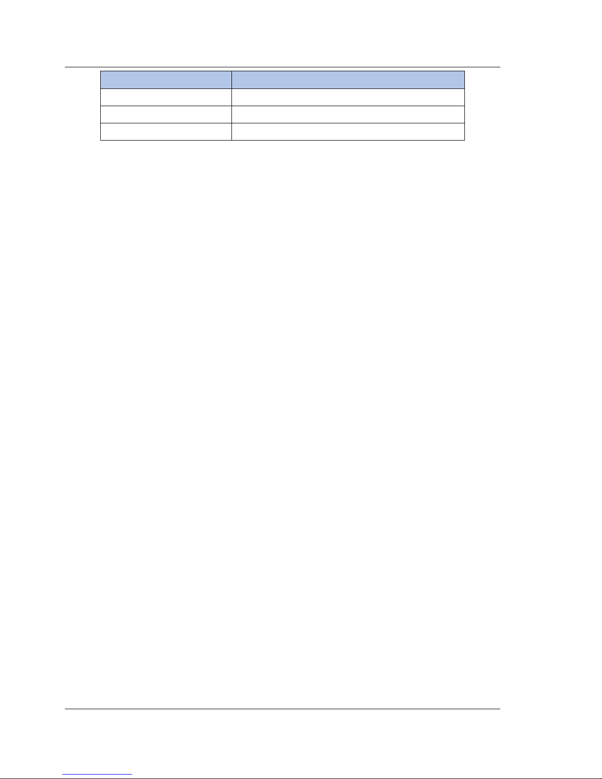
The POST test items are shown in the table below.
Page 30
FUJITSU PSWITCH User’s Guide
30 December/2018
Item
Definition
Basic POST tests
Basic test items like CPU test, SSD test, etc.
MAC loopback test
MAC loopback test
PHY loopback test
PHY loopback test
With show post command, you can check the currently enabled POST test item.
(Config)#show post
Basic POST tests............................... ON
MAC loopback test.............................. ON
PHY loopback test.............................. ON
With post command, you can control the POST test items. Tests which consume
time to run are MAC loopback test and PHY loopback test. These tests can be
skipped with the following command.
With no post command, disable the MAC loopback test.
(Config)#no post maclb
With no post command, disable the PHY loopback test.
(Config)#no post phylb
Also, you can enable only Basic POST tests with post basic command.
(Config)#post basic
With copy command, copy the settings to startup-config.
(Config)#copy system:running-config nvram:startup-config
The test items which you disabled will be skipped in the next boot. Reboot the
switch.
(Config)#reboot runtime
Page 31

User’s Guide FUJITSU PSWITCH
December/2018 31
3 Software Feature
The major features of this switch’s software are introduced in this chapter. The complete
set of software function is listed up in the section ‘3.4. Software Feature List’.
3.1. Functional Overview
3.1.1. Switch Management
This switch supports the following protocols for management.
Command Line Interface (CLI) -
Simple Network Management Protocol (SNMP) -
Network Configuration Protocol (NETCONF) -
Open vSwitch Database (OVSDB) -
The switch has three management interfaces – console port, management port,
and inbound network interface. If the management port or the network interface is
properly connected to the network, remote management of the switch is available
through these port or interface.
3.1.1.1. Command Line Interface (CLI)
The command-line interface (CLI) is a text-based way to manage and monitor the
system. You can access the CLI by using a direct serial connection or by using a
remote logical connection with telnet or SSH.
Default User Login
To login CLI engine, the default user name is “admin” and password is zero-string.
3.1.1.2. SNMP (Simple Network Manageffment Protocol)
The SNMP component provides a machine-to-machine interface for the product
family. This includes the ability to configure the network device, view settings and
statistics, and upload or download code or configuration images. The agent
Page 32

FUJITSU PSWITCH User’s Guide
32 December/2018
includes a get-bulk command to reduce network management traffic when
retrieving a sequence of Management Information Base (MIB) variables and an
elaborate set of error codes for improved reporting to the network control station.
The extensible and advanced design of the SNMP component makes adding
remote manageability to networked devices undemanding. The agent allows a
network control station to retrieve reports from the networked device.
These reports are based upon the defined objects in the MIB. The agent queries,
reports, and sets MIB variables based upon directions from the network control
station or upon preset conditions.
The SNMP agent can accept multi-requests from different managers, and send
response one by one. When SNMP agent receives first request and reply it
immediately, then serves next request packets.
3.1.1.2.1. Supported versions
The SNMP agent supports the SNMPv1, SNMPv2c, or SNMPv3 protocols.
SNMP version 3 (SNMPv3) adds security and remote configuration enhancements
to SNMP. The software has the ability to configure SNMP server, users, and traps for
SNMPv3. Any user can connect to the switch using the SNMPv3 protocol, but for
authentication and encryption, you need to configure a new user profile.
3.1.1.2.2. MIB
The SNMP agent supports adding any standard SMIv1 or SMIv2 MIB to the agent.
This includes standard RFC MIBs as well as customer-defined MIBs. For FUJITSU
PSWITCH products, a private MIB is provided . It contains configuration and
statistics reporting objects for features supported by these products that are not
covered by standard RFCs.
3.1.1.2.3. SNMP Alarms and Trap Logs
The system logs events with severity codes and timestamps. The events are sent as
SNMP traps to a trap recipient list. You can configure SNMP groups and users that
can manage traps that the SNMP agent generates.
3.1.1.3. RMON (Remote Monitoring)
RMON is a base technology used by network management applications to manage
Page 33

User’s Guide FUJITSU PSWITCH
December/2018 33
a network. Troubleshooting and network planning can be accomplished through
the network management applications.
The network monitor monitors traffic on a network and records selected portions of
the network traffic and statistics. The collected traffic and statistics are retrieved
using SNMP and CLI. The data collected is defined in the RMON MIB, RFC 2819.
A device that supports gathering and reporting the RMON data is referred to as an
RMON probe or RMON Agent. An RMON probe provides RMON data to an RMON
Manager for analysis and presentation to the user. An RMON probe may be
embedded in a supported RMON groups as follows:
Statistics, History, Alarm and Event of RFC 2819. -
All groups of RFC 3273. -
All groups of RFC 3434. -
3.1.1.4. NETCONF (Network Configuration Protocol)
The NETCONF protocol provides a small set of low-level operations to manage
device configurations and retrieve device state information. The base protocol
provides operations to retrieve, configure, copy, and delete configuration
datastores. The switch supports “running” and “start-up” configuration to be get or
modified.
The syntax and XML encoding of the protocol operations are formally defined in
the XML schema in RFC4741 Appendix B.
The configuration can be defined in multiple formats, such as XML and text. For
text format, configuration statements are formatted as ASCII text, using the
newline character, tabs and other white space, braces, and square brackets to
indicate the hierarchical relationships between the statements. This is the format
used in configuration files stored on the switch and displayed by the CLI “show
running-config” command.
Currently we only support text format. All configurations - either in response of
<get-config> or in request of <edit-config> - are in text format, they are exactly the
same as CLI statements used in CLI.
SSH is the widely used protocol for NETCONF sessions. The default SSH port for
NETCONF is 830. Only support SSHv2 transport protocol at present.
3.1.1.4.1. NETCONF Operations
The NETCONF protocol provides a set of operations to manage and retrieve switch
Page 34

FUJITSU PSWITCH User’s Guide
34 December/2018
configuration.
The following table provides a list of protocol operations supported by the switch.
Operation
Description
Get-config
Retrieve all or part of the running or startup configuration.
get
Retrieve running configuration and device state information.
edit-config
Load all or part of a specified configuration to the running or
startup configuration.
copy-config
Replace the target running or startup configuration with a
source running or startup configuration.
delete-config
Delete startup configuration.
lock
Lock the running configuration to prevent other users (via
another NETCONF session) from changing it.
unlock
Release a locked running configuration.
close-session
Request graceful termination of a NETCONF session.
kill-session
Force the termination of a NETCONF session.
3.1.1.4.2. NETCONF Tag Elements and Values
Following are examples of the NETCONF protocol operations with tag elements and
values.
<get-config>
Usage :
Response from the switch:
<rpc message-id="201" xmlns="urn:ietf:params:xml:ns:netconf:base:1.0">
<get-config>
<source>
<running/>
</source>
<filter type="subtree">
<config-text/>
</filter>
</get-config>
</rpc>
<rpc-reply message-id="201" xmlns="urn:ietf:params:xml:ns:netconf:base:1.0">
<data >
<config-text >
<!-- Configration text… -->
</config-text >
</data >
</rpc-reply>
Page 35
User’s Guide FUJITSU PSWITCH
December/2018 35
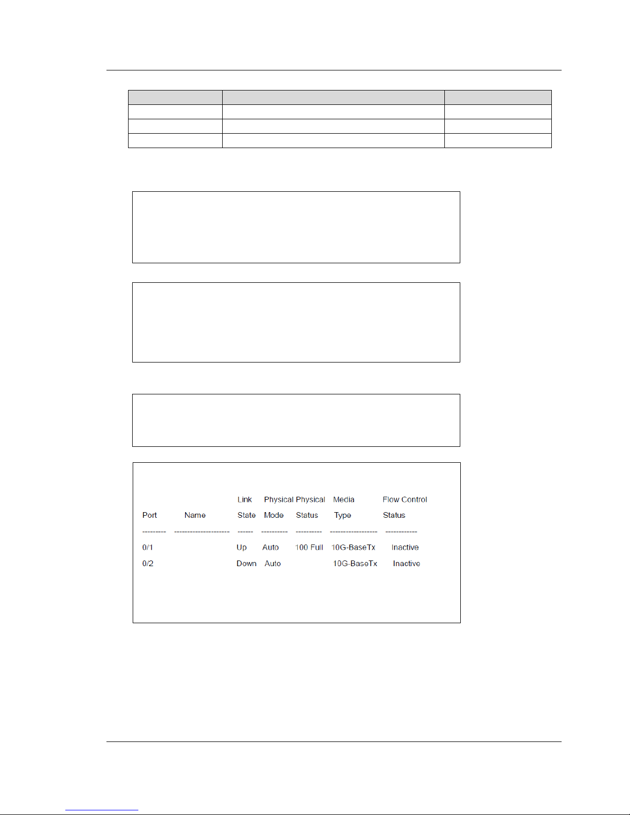
Supported tag elements and values:
Tag Element
Description
Value
source
The configration text you want to retrieve.
running or startup
filter
The filter type.
subtree
config-text
Contains the configuration in CLI format.
<get>
Usage :
Response from the switch:
Usage :
Response from the switch:
<rpc-reply message-id="201" xmlns="urn:ietf:params:xml:ns:netconf:base:1.0">
<data>
<config-text >
<!-- Configration text -->
</config-text >
</data >
</rpc-reply>
<rpc message-id="201" xmlns="urn:ietf:params:xml:ns:netconf:base:1.0">
<get>
<show-command>show interfaces status all </show-command>
</get->
</rpc>
<rpc-reply message-id="201" xmlns="urn:ietf:params:xml:ns:netconf:base:1.0">
<data >
<config-text >
</config-text >
</data >
</rpc-reply>
<rpc message-id="201" xmlns="urn:ietf:params:xml:ns:netconf:base:1.0">
<get>
<filter type="subtree">
<config-text/>
</filter>
</get->
</rpc>
Page 36

FUJITSU PSWITCH User’s Guide
36 December/2018
Supported tag elements and values:
Tag Element
Description
Value
filter
The filter type.
subtree
show-command
Contains the CLI show command
and the command must be valid
and complete. Now switch
supports only one command to
display information.
This tag element cannot be used
with other tag elements, and it
should be used above.
config-text
Configuration in CLI format.
<edit-conifg>
Usage :
Response from the switch:
Usage :
<rpc message-id="201" xmlns="urn:ietf:params:xml:ns:netconf:base:1.0">
<get-config>
<target >
<running/>
</target>
<default-operation>merge</default-operation>
<error-option>continue-on-error</error-option>
<config-text>ip telnet server enable
</config-text>
<edit-config>
</rpc>
<rpc-reply message-id="201" xmlns="urn:ietf:params:xml:ns:netconf:base:1.0">
<ok/>
</rpc-reply>
<rpc message-id="201" xmlns="urn:ietf:params:xml:ns:netconf:base:1.0">
<edit-config>
<target >
<running/>
</target>
<default-operation>merge</default-operation>
<error-option>continue-on-error</error-option>
<config-text>ip telnet server enable
snmp-server port 0
netconf maxsessions 20
hostname abc
</config-text>
<edit-config>
</rpc>
Page 37

User’s Guide FUJITSU PSWITCH
December/2018 37
Response from the switch:
Supported tag elements and values:
Tag Element
Description
Value
target
The configuration text you want to
edit.
running or startup
default-opefation
Set the default operation for the
„edit-config“ request.
merge: The new
configuration is merged
with the target
configuration at the
correcponding level.
This value is only for
„running“ configuration.
replace: The new
configuration replaces
the target
configuration.
If there is no
„default-operation“ valu
e, the default value will
be „merge“ and only for
„running“ configuration.
error-option
Set the option to handle
configuration error.
continue-on-error:
Continue to process
configuration data on
error. The error-option
support only
„continue-on-error“ mod
e.
config-text
Configuration in CLI format. Switch
not allows any show command in
<rpc-reply message-id="201" xmlns="urn:ietf:params:xml:ns:netconf:base:1.0">
<rpc-error>
<error-type>application</error-type>
<error-tag>operation-failed</error-tag>
<error-severity>error</error-severity>
<error-message> Some error or warning occur, please check below
message…
ip telnet server enable
snmp-server port 0
Couldn’t set the SNMP server port number.
netconf maxsessions 20
Invalid MAX-session value.
hostname abc
</error-message>
</rpc-errro>
</rpc-reply>
Page 38

FUJITSU PSWITCH User’s Guide
38 December/2018
<edit-config> operation.
error-message
If any error happend after execute
CLI commands, switch will
response <rpc-error> with
<error-message> tag element.
And the <error-message> will
include all execution error
information in Cli format.
<copy-config>
Usage :
Response from the switch:
Supported tag elements and values:
Tag Element
Description
Value
target
Configuraiton that needs to be
changed.
running or startup
source
Source configuration
running or startup
<delete-config>
Usage :
Response from the switch:
<rpc message-id="201" xmlns="urn:ietf:params:xml:ns:netconf:base:1.0">
<copy-config>
<target >
<startup/>
</target>
<source>
<running/>
</source>
</copy-config>
</rpc>
<rpc-reply message-id="201" xmlns="urn:ietf:params:xml:ns:netconf:base:1.0">
<ok/>
</rpc-reply>
<rpc-reply message-id="201" xmlns="urn:ietf:params:xml:ns:netconf:base:1.0">
<ok/>
</rpc-reply>
<rpc message-id="201" xmlns="urn:ietf:params:xml:ns:netconf:base:1.0">
<delete-config>
<target >
<startup/>
</target>
</delete-config>
</rpc>
Page 39
User’s Guide FUJITSU PSWITCH
December/2018 39
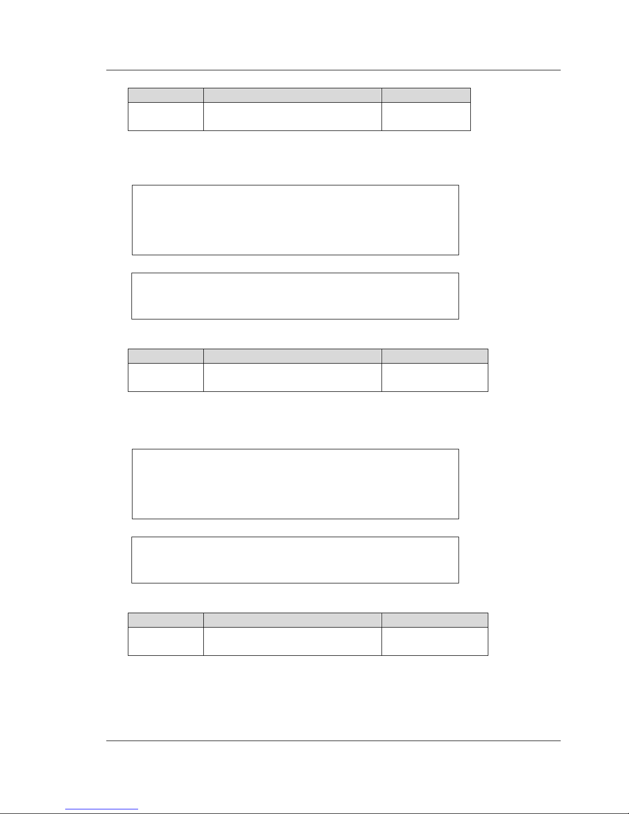
Supported tag elements and values:
Tag Element
Description
Value
target
Configuraiton that needs to be
deleted.
startup
<lock>
Usage :
Response from the switch:
Supported tag elements and values:
Tag Element
Description
Value
target
Configuraiton that needs to be
locked.
running or startup
<unlock>
Usage :
Response from the switch:
Supported tag elements and values:
Tag Element
Description
Value
target
Configuraiton that needs to be
unlocked.
running or startup
<rpc-reply message-id="201" xmlns="urn:ietf:params:xml:ns:netconf:base:1.0">
<ok/>
</rpc-reply>
<rpc message-id="201" xmlns="urn:ietf:params:xml:ns:netconf:base:1.0">
<lock>
<target >
<startup/>
</target>
</lock>
</rpc>
<rpc message-id="201" xmlns="urn:ietf:params:xml:ns:netconf:base:1.0">
<unlock>
<target >
<startup/>
</target>
</unlock>
</rpc>
<rpc-reply message-id="201" xmlns="urn:ietf:params:xml:ns:netconf:base:1.0">
<ok/>
</rpc-reply>
Page 40
FUJITSU PSWITCH User’s Guide
40 December/2018
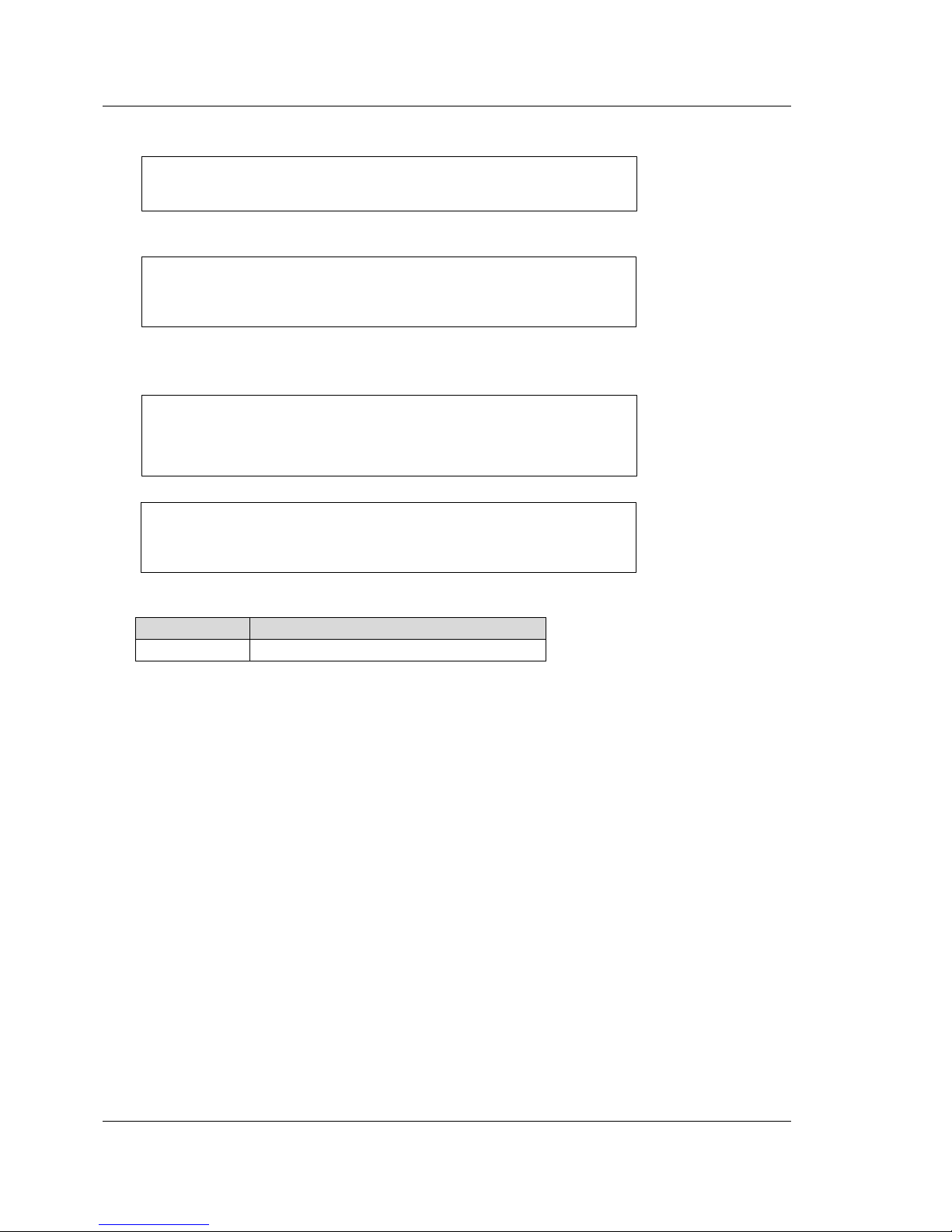
<close-session>
Usage :
Response from the switch:
<kill-session>
Usage :
Response from the switch:
Supported tag elements and values:
Tag Element
Description
session-id
ID number of the session to be killed
3.1.1.5. OVSDB (Open vSwitch Database)
OVSDB is the Open vSwitch Database management protocol. This is light database,
user can define the database schema, and it would use the Json RPC to work
between the client and server. User can use the client application to send the
request to server. Server would send the response after process request. OVSDB
define the some action can use. Most be used is the transact and monitor. User and
use the transact action to set the ovsdb database and use the monitor to display
the database information. This database application usually used to maintain
database that schema is follow the Open vSwitch or VTEP.
The software provides the OVSDB server but not used all VTEP schema, because
some action is not support by hardware designed of this switch, if provide the
standard schema would happen the user confuse. In the next section would
description this modify schema. In the other hand, Manager can use the OVSDB
client application (example: ovsdb-clent, vtep-clt) to connect the server. They can
set the entry that it is match the schema. Manager can used the dump command
<rpc-reply message-id="201" xmlns="urn:ietf:params:xml:ns:netconf:base:1.0">
<ok/>
</rpc-reply>
<rpc message-id="201" xmlns="urn:ietf:params:xml:ns:netconf:base:1.0">
<kill-session>
<session-id>3</session-id>
</kill-session>
</rpc>
<rpc-reply message-id="201" xmlns="urn:ietf:params:xml:ns:netconf:base:1.0">
<ok/>
</rpc-reply>
<rpc message-id="201" xmlns="urn:ietf:params:xml:ns:netconf:base:1.0">
<close-session/>
</rpc>
Page 41

User’s Guide FUJITSU PSWITCH
December/2018 41
to know the database status by OVSDB client application. And the switch would set
configure after manager send the request to the OVSDB server and this request is
valid.
OVSDB services include OVSDB server, and VTEP service. While enabling OVSDB
services, system starts OVSDB server, and VTEP service. And initialize server
connection method, also physical switch, and physical port table of VTEP schema. It
will take a few seconds. VTEP service monitors and converts configuration of VTEP
schema in OVSDB server into switch’s VXLAN component.
The switch in hardware VTEP mode, all physical and trunk port are available for
OVSDB management.
The switch must configure default VTEP source IP address for OVSDB management.
Network manager can configure hardware VTEP through OVSDB client application
or switch CLI interface.
3.1.1.5.1. Schema Format
Hardware_vtep database schema
DCVPN switch which support OVSDB hardware_vtep database schema can be
managed by network virtualization controller using OVSDB protocol.
The Hardware_vtep database schema designs according to OVSDB protocol.
Management through OVSDB hardware_vtep database, the controller can have
clear relationship of mapping physical to logical switch.
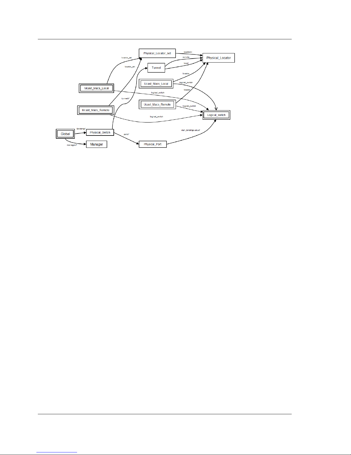
Table relationships
The following diagram shows the relationship among supported tables in the
database.
Tables that are part of the ‘‘root set’’ are shown with double borders. Each edge
leads from the table that contains it and maps to the table that its value represents.
Edges are labeled with their column names, followed by a constraint on the
number of allowed values: ? for zero or one, * for zero or more. + for one or more.
Page 42
FUJITSU PSWITCH User’s Guide
42 December/2018
Global Table
This table gives top-level view of VXLAN and OVSDB management configuration for
the switch.
Column:
switches: The physical switch. This column maps to a row of physical switch table.
Group: Database Configuration
managers: Set of database clients. Each of column maps to a row of manager table.
Manager Table
This table maintains connection configuration, and status to database clients.
Column:
target: Connection method for managers. Supported methods are list below.
ssl:ip[:port]
The server use ssl transport protocol assigned specific ip address, and optional ssl port
(default 6640) to connect to client.
tcp:ip[:port]
The server use tcp transport protocol assigned specific ip address, and optional tcp port
(default 6640) to connect to client.
pssl:[port][:ip]
The server use ssl transport protocol assigned optional specific ip address, and optional
ssl port (default 6640) to listen ssl connection.
ptcp:[port][:ip]
The server use tcp transport protocol assigned optional specific ip address, and
Page 43

User’s Guide FUJITSU PSWITCH
December/2018 43
optional tcp port (default 6640) to listen tcp connection.
Group: Database Configuration
max_backoff: Number of milliseconds the switch retries next connection to client.
inactivity_probe: Number of milliseconds the switch sends inactivity probe message to
client. A value of 0 means probe is disabled.
Group: Status
is_connected:
true: If connection is established. Otherwise is false.
status : last_error
Only exist if an error occurred, it describes last error statement.
status : state
The state of connection:
VOID: Connection is disabled.
BACKOFF: Attempting to reconnect at an increasing period.
CONNECTING: Attempting to connect.
ACTIVE: Connected, remote host responsive.
IDLE: Connection is idle. Waiting for response.
status : sec_since_connect
The amount of seconds since this manager last successfully connected to database.
status : sec_since_disconnect
The amount of seconds since this manager last disconnected from database.
status : locks_held
The list of the names of OVSDB locks that the connection holds.
status : locks_waiting
The list of the names of OVSDB locks that the connection is currently waiting to acquire.
status : locks_lost
The list of the names of OVSDB locks that the connection has had stolen by another
OVSDB client.
status : n_connections
Number of active connections, if more than one, connects to server configured passive
connection method.
Group: Connection Parameters
Other_config : dscp
Specify the DSCP field in IP header for network traffic between the manager and the
database server, when connection is established.
Physical_Switch Table
This table maintains switch’s configuration in the view of network virtualize
controller.
Column:
ports: The physical ports within the switch. Each of column maps to rows of physical port
table.
Page 44

FUJITSU PSWITCH User’s Guide
44 December/2018
tunnels: Tunnels created by this switch as instructed by the NVC. Each of column maps to
rows of tunnel table.
Group: Network Status
management_ips: The switch management IPv4 or IPv6 addresses.
tunnel_ips: The switch VTEP IPv4 addresses.
Group: Identification.
name: Symbolic name for the switch. It’s the switch host name.
description: An extended description for the switch. It’s the CLI login banner.
Physical_Port Table
This table maintains switch’s port and VLAN binding configuration.
Column:
van_bindings: Identifies VLAN on the physical port is bound to logical switch.
Group: Identification.
name: Symbolic name for the physical port. The port name must be switch physical or
trunk port name.
description: An extended description for the physical port.
Tunnel Table
This table maintains tunnels created by physical_switch. Multiple logical switches
utilize tunnel specified by local and remote tunnel end-points. If a tunnel does not
added to any logical switch, this row will be removed from tunnel table.
Column:
local: Tunnel end-point local to the physical switch. This column maps to a row of
physical_locator.
remote: Tunnel end-point remote to the physical switch. This column maps to a row of
physical_locator.
Logical_Switch Table
This table maintains logical VXLAN switch.
Column:
local: Tunnel end-point local to the physical switch. This column maps to a row of
physical_locator.
remote: Tunnel end-point remote to the physical switch. This column maps to a row of
physical_locator.
Page 45

User’s Guide FUJITSU PSWITCH
December/2018 45
Group: Per Logical_switch Tunnel Key.
tunnel_key: This value is VXLAN VNI.
Group: Identification.
name: Symbolic name for the logical switch.
description: An extended description for the switch.
Ucast_Macs_Local Table
This table maintains unicast MAC addresses on physical ports by switch.
Column:
MAC: A MAC address that has been learned by this switch.
logical_switch: This column map to a row of logical switch table.
locator: Local VTEP. This column maps to a row of physical locator table.
ipaddr: The IP address to which this MAC corresponds.
Ucast_Macs_Remote Table
This table maintains unicast MAC addresses learned by network virtualize
controller.
Column:
MAC: A MAC address that has been learned by the NVC.
logical_switch: This column map to a row of logical switch table.
locator: Hypervisor, or emote VTEP. This column maps to a row of physical locator table.
ipaddr: The IP address to which this MAC corresponds.
Mcast_Macs_Local Table
This table maintains multicast MAC addresses learned on physical ports by switch.
Column:
MAC: This switch does not support multicast packet forwarding. Hence, only reserved
address “unknown-dst” is meaningful for BUM packets.
logical_switch: This column map to a row of logical switch table.
Locator_set: The physical locator set contain one or more local VTEP.
ipaddr: The IP address to which this MAC corresponds.
Mcast_Macs_Remote Table
This table maintains multicast MAC addresses learned by network virtualize
Page 46

FUJITSU PSWITCH User’s Guide
46 December/2018
controller.
Column:
MAC: This switch does not support multicast packet forwarding. Hence, only reserved
address “unknown-dst” is meaningful for BUM packets.
logical_switch: This column map to a row of logical switch table.
Locator_set: The physical locator set contain one or more local VTEP.
ipaddr: The IP address to which this MAC corresponds.
Physical_Locator_Set Table
This table includes a set of one or more physical locators.
Column:
locators: Set of 1 or more physical locators. Each of entry maps to a row of physical locator
table.
Physical_Locator Table
This table includes local and remote VTEP IP addresses.
Column:
encapsulation_type: Must be “vxlan_over_ipv4”.
dst_ip: VTEP IPv4 address.
Supported configurable Tables
The following columns of each table are supported to configure hardware VTEP
from OVSDB client application.
Table
Column
Physical_Switch
name
description
Physical_Port
description
vlan_bindings
Logical_Switch
name
description
tunnel_key
Page 47

User’s Guide FUJITSU PSWITCH
December/2018 47
Ucast_Macs_Remote
MAC
logical_switch
locator
ipaddr
Mcast_Macs_Remote
MAC
logical_switch
locator
ipaddr
Physical_Locator_Set
locators
Physical_Locator
encapsulation_type
dest_ip
vtep.schema
{
"name": "hardware_vtep",
"cksum": "58544667 7319",
"tables": {
"Global": {
"columns": {
"managers": {
"type": {"key": {"type": "uuid",
"refTable": "Manager"},
"min": 0, "max": "unlimited"}},
"switches": {
"type": {"key": {"type": "uuid", "refTable": "Physical_Switch"},
"min": 0, "max": "unlimited"}}
},
"maxRows": 1,
"isRoot": true},
"Physical_Switch": {
"columns": {
"ports": {
"type": {"key": {"type": "uuid", "refTable": "Physical_Port"},
"min": 0, "max": "unlimited"}},
"name": {"type": {"key": {"type": "string", "minLength": 1, "maxLength": 64}}},
"description": {"type": {"key": {"type": "string", "maxLength": 2000}}},
"management_ips": {
"type": {"key": {"type": "string"}, "min": 0, "max": "unlimited"}},
"tunnel_ips": {
"type": {"key": {"type": "string"}, "min": 0, "max": 1}},
"tunnels": {
"type": {"key": {"type": "uuid", "refTable": "Tunnel"},
"min": 0, "max": "unlimited"}}},
"maxRows": 1,
"indexes": [["name"]]},
"Physical_Port": {
"columns": {
"name": {"type": {"key": {"type": "string", "minLength": 1, "maxLength": 60}}},
"description": {"type": {"key": {"type": "string", "maxLength": 64}}},
"vlan_bindings": {
"type": {"key": {"type": "integer",
"minInteger": 1, "maxInteger": 4093},
"value": {"type": "uuid", "refTable": "Logical_Switch"},
"min": 0, "max": 1}}},
"maxRows": 142},
"Tunnel": {
Page 48

FUJITSU PSWITCH User’s Guide
48 December/2018
"columns": {
"local": {
"type": {"key": {"type": "uuid",
"refTable": "Physical_Locator"}}},
"remote": {
"type": {"key": {"type": "uuid",
"refTable": "Physical_Locator"}}}}},
"Logical_Switch": {
"columns": {
"name": {"type": {"key": {"type": "string", "minLength": 1, "maxLength": 32}}},
"description": {"type": {"key": {"type": "string", "maxLength": 64}}},
"tunnel_key": {"type": {"key": {"type": "integer", "minInteger": 1, "maxInteger": 16777214}, "min": 0, "max": 1}}},
"maxRows": 1024,
"isRoot": true,
"indexes": [["name"]]},
"Ucast_Macs_Local": {
"columns": {
"MAC": {"type": "string"},
"logical_switch": {
"type": {"key": {"type": "uuid",
"refTable": "Logical_Switch"}}},
"locator": {
"type": {"key": {"type": "uuid",
"refTable": "Physical_Locator"}}},
"ipaddr": {"type": "string"}},
"isRoot": true,
"maxRows": 32768},
"Ucast_Macs_Remote": {
"columns": {
"MAC": {"type": "string"},
"logical_switch": {
"type": {"key": {"type": "uuid",
"refTable": "Logical_Switch"}}},
"locator": {
"type": {"key": {"type": "uuid",
"refTable": "Physical_Locator"}}},
"ipaddr": {"type": "string"}},
"isRoot": true,
"maxRows": 32768},
"Mcast_Macs_Local": {
"columns": {
"MAC": {"type": "string"},
"logical_switch": {
"type": {"key": {"type": "uuid",
"refTable": "Logical_Switch"}}},
"locator_set": {
"type": {"key": {"type": "uuid",
"refTable": "Physical_Locator_Set"}}},
"ipaddr": {"type": "string"}},
"isRoot": true},
"Mcast_Macs_Remote": {
"columns": {
"MAC": {"type": "string"},
"logical_switch": {
"type": {"key": {"type": "uuid",
"refTable": "Logical_Switch"}}},
"locator_set": {
"type": {"key": {"type": "uuid",
"refTable": "Physical_Locator_Set"}}},
"ipaddr": {"type": "string"}},
"isRoot": true},
"Physical_Locator_Set": {
"columns": {
"locators": {
"type": {"key": {"type": "uuid", "refTable": "Physical_Locator"},
"min": 1, "max": 512},
"mutable": false}}},
"Physical_Locator": {
"columns": {
"encapsulation_type": {
"type": {
"key": {
"enum": ["set", ["vxlan_over_ipv4"]],
"type": "string"}},
"mutable": false},
"dst_ip": {"type": "string", "mutable": false}},
Page 49

User’s Guide FUJITSU PSWITCH
December/2018 49
"indexes": [["encapsulation_type", "dst_ip"]],
"maxRows": 513},
"Manager": {
"columns": {
"target": {"type": "string"},
"max_backoff": {
"type": {"key": {"type": "integer",
"minInteger": 1000},
"min": 0, "max": 1}},
"inactivity_probe": {
"type": {"key": "integer", "min": 0, "max": 1}},
"other_config": {
"type": {"key": "string", "value": "string", "min": 0, "max": "unlimited"}},
"is_connected": {
"type": "boolean",
"ephemeral": true},
"status": {
"type": {"key": "string", "value": "string", "min": 0, "max": "unlimited"},
"ephemeral": true}},
"indexes": [["target"]],
"isRoot": false}},
"version": "1.3.0"}
3.1.1.6. Configuration Management
The switch provides a set of configuration management operations. The
configuration of the currently running system is known as the ‘running-config’.
Changes you make to the configuration while the switch is operating are
immediately reflected to the running-config. Because these changes are temporary
in memory, rebooting the system or reloading a configuration deletes such
changes. You need to save the changes to make them permanent by CLI command
(copy).
The ‘startup-config’ is one of the permanent configurations saved in the storage.
This configuration is used at the startup of the switch. The switch has a capability
to store three different configurations in the permanent storage. They are called as
the ‘first-config’, ‘second-config’, and ‘third-config’. The startup config represents
one of these three configurations specified by CLI command (bootselect).
The configuration can be initialized to the factory default by CLI command (clear
config).
3.1.1.7. Firmware Upgrade
The firmware is upgraded (or downgraded) by CLI command (copy). Upgrading
firmware means downloading a new firmware image to the switch and rebooting
the system. The switch has FTP, TFTP, SFTP and SCP client functions. A server
running at least one of these services are required to download the image.
The system has a capability to have two firmware images in the switch storage. You
can specify which image you update with the argument to the copy command. The
Page 50

FUJITSU PSWITCH User’s Guide
50 December/2018
image to be loaded in the next reboot is set up by CLI command (bootselect).
The system checks if the firmware image is correct after it has been downloaded. If
the image CRC check fails, the image file is dropped. This check prevents the fail
runtime image from causing the switch crash.
3.1.1.8. System and CLI logging
The system logs events taken place in the switch. The system logs can be stored on
memory, on the switch storage, or on the device outside of the switch depending
on the setting. The system log is configured by CLI command (logging).
3.1.1.9. Auto Discovery
If network management application supports the Auto Discovery feature, the
software discovers and identifies the switch and automatically set up the switch
with pre-defined parameters to the application. This feature reduces the initial
effort of introducing the switch in to network.
3.1.1.10. Other functions
There are many other various management functions available on the switch. You
can make use of common CLI commands like ping, and traceroute.
The system has a built-in sFlow agent that can monitor network traffic on each port
and generate sFlow data to a sFlow collector. sFlow helps to provide visibility into
network activity, which enables effective management and control of network
resources.
3.1.2. Layer 2 Switching
3.1.2.1. Jumbo Frames
The Jumbo Frames technology is employed in certain situations to reduce the task
load on a server CPU and to transmit large amounts of data efficiently. The Jumbo
Frames Technology predominantly appears where certain applications would
benefit from using a larger frame size (for example, Network File System (NFS)).
The larger frame size eliminates some of the need for fragmentation, leading to
greater throughput. The increase in throughput is particularly valuable on data
Page 51
User’s Guide FUJITSU PSWITCH
December/2018 51
center servers where the larger frame size increases efficiency of the system and
allows processing of more requests.
3.1.2.2. Flow Control
Flow control enables lower speed switches to communicate with higher speed
switches by requesting that the higher speed switch refrains from sending packets.
Transmissions are temporarily halted to prevent buffer overflows. This feature is
typically used with iSCSI disk arrays.
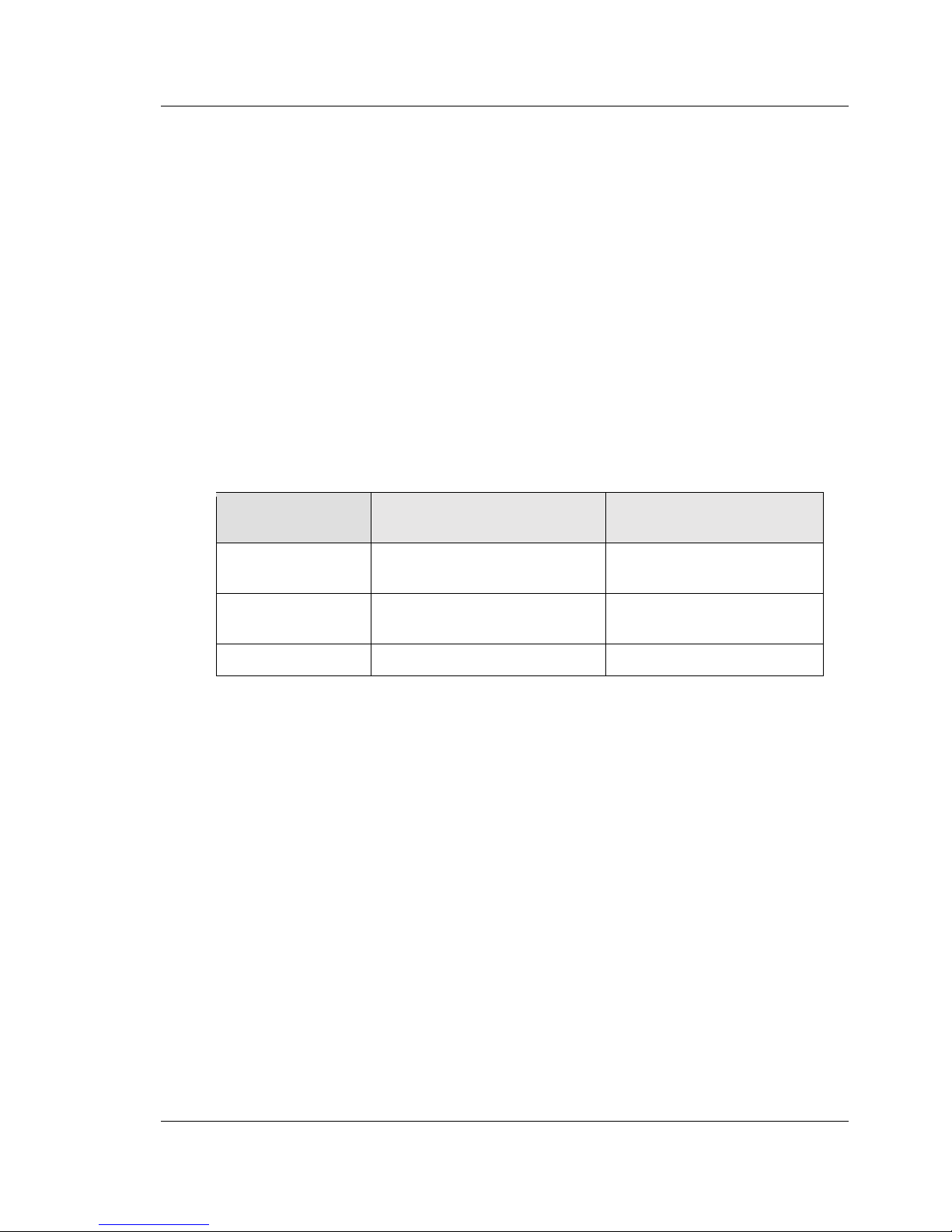
This feature enables you to configure the switch to use symmetric, asymmetric or
no flow control. Asymmetric flow control allows the switch to respond to received
PAUSE frames, but the port cannot generate PAUSE frames. Symmetric flow control
allows the switch to both respond to, and generates MAC control PAUSE frames.
With no flow control, neither responding nor generating to the PAUSE frame is
done.
Response to
received PAUSE frames
Generation of
PAUSE frames
Symmetric
Flow Control
Enabled
Enabled
Asymmetric
Flow Control
Enabled
Disabled
No Flow Control
Disabled
Disabled
Table 3-1: Flow Control
802.3x Flow control, the MAC control PAUSE operation allows traffic from one
device to be throttled for a specified period of time and is defined for devices that
are directly connected. A device that wishes to inhibit transmission of data frames
from another device on the LAN transmits a PAUSE frame as defined in the IEEE
specification.
When Symmetric flow control is enabled, the ports asserts back pressure to the
MAC, the MAC will respond by generating PAUSE frames, and the partner device
will respond by stopping packet transmission to avoid packet loss. The ports are
also capable of throttling the transmit rate in response to the PAUSE frames
received from peer. When transmission of symmetric flow control frames is enabled,
the entire switch is placed in ingress drop mode. When in ingress drop mode, the
switch will behave like any other ingress buffered switch and exhibit head of line
blocking during times of congestion.
Page 52
FUJITSU PSWITCH User’s Guide
52 December/2018
3.1.2.3. Port Locator
The port locator identify ports that have network cabling errors and/or cabling
complications (mis-wiring) by providing a command that blinks a single interface’s
LED or the LEDs of multiple interfaces and turns off all other interface LEDs so that
the mis-wired interface can be easily identified.
In this TOR switch, one LED for link and a second for activity, only the link LED is used for
the port locator function. The other details refer the table below.
Port LED
Port-Locator
One or more Port-Locator Enable
Port-Locator is disable
on all interface
Enabled Port
Disabled Port
ACT LED
Off
Off
Normal mode
(Refer to "1.3 LED
Identification")
Link LED
Link-status-up:
Blinking Green
Link-status-up:
Solid Green
Link-status-down: Off
Link-status-down: Off
Table 3-2: Port-Locator
3.1.2.4. MAC Address Tables
3.1.2.4.1. Forwarding, Aging, Learning
Forwarding, Aging, and Learning are considered to be one component with three
related functions. Those functions are summarized as follows:
Forwarding
Forwarding occurs when a frame is processed completely by either the bridge
function or the routing function. At layer 2, frames are forwarded according to their
MAC address type, which is either unicast or multicast. A unicast frame is forwarded
in accordance with the address entry in the networking device’s address tables or
filtering database. The frame is forwarded to the port associated with the unicast
address in the address entry. Multicast frames are forwarded in accordance with
their address entry in the switch filtering database. If no entry exists, the frame is
forwarded to all ports in the associated VLAN.
Aging
An address aging time-out parameter based on the 802.1D specification is
included in the networking device. This parameter is a persistent input and output
Page 53

User’s Guide FUJITSU PSWITCH
December/2018 53
parameter and represents time in seconds. Aging is controlled by microcode. An
address aging time-out parameter is user configurable. The parameter minimum
and maximum values may be bounded by networking device implementation.
Learning
Learning and managing MAC addresses is according to the IEEE 802-1D-1998 and
802-1Q-1998 standards. This software supports Independent VLAN Learning (IVL).
All learning takes place in the underlying device. The forwarding database is
populated from messages received from the platform.
Independent VLAN Learning
Independent VLAN Learning (IVL) allows unicast address-to-port mappings to be
created based on a MAC Address in conjunction with a VLAN ID.
This arrangement associates the MAC Address only with the VLAN on which the
frame was received. Therefore, frames are forwarded based on their unicast
destination address as well as their VLAN membership. This configuration affords
multiple occurrences of an address in the forwarding database. Each address
associates with a unique VLAN. Care must be taken in the administration of
networks, as multiple instances of a MAC address, each on a different VLAN, can
quickly eat up address entries.
Each VLAN is associated with its own forwarding database. Hence the number of
forwarding databases equals the number of VLANs supported.
The MAC address stored is supplemented by a 2-byte VLAN ID. The first 2 bytes of a
forwarding database entry contain the VLAN ID associated, and the next 6 bytes
contain the MAC address. There is a one-to-one relationship between VLAN ID and
FID (forwarding database ID)
3.1.2.4.2. Static and Dynamic MAC Address Tables
You can add static entries to the switch’s MAC address table and configure the
aging time for entries in the dynamic MAC address table. Currently static entries
could be added by Port Security and EVB VDP components. You can also search for
entries in the dynamic table based on several different criteria.
3.1.2.4.3. Static MAC Filtering
Static MAC Filtering allows you to add a number of unicast or multicast MAC
addresses directly to the forwarding database. This is typically a small number
relative to the total size of the database. Associated with each static MAC address is
Page 54

FUJITSU PSWITCH User’s Guide
54 December/2018
a set of source ports, a set of destination ports and VLAN information.
Any packet with a particular static MAC address in a particular VLAN is admitted
only if the ingress port is in the set of source ports; otherwise, the packet is
dropped. On the egress side, the packet, if admitted, is sent out of all the ports that
are in the set of destination ports.
Upon ingress, each packet's destination MAC address is compared against the
forwarding database. If the address is not in the table, the packet is flooded to all
members of the VLAN. If the address is in the table, then it is checked to see if it
has been defined as a filter. If the MAC address is not defined as a filter, then the
packet is forwarded to destination port.
If the specific destination MAC address is defined as a filter, then the ingress port
number is compared to the set of source ports listed for the address. If the port of
ingress is not in the set of source ports, then the packet is immediately discarded.
If the ingress port is a member of the set of source ports, then the packet is
admitted.
At the egress port, if the destination port number is in the set of destination ports,
the packet is transmitted. If the destination port is not in the set of destination
ports, then the packet is discarded.
Static entries are never aged and can only be removed by user command. The
number of static mac filters supported on the system is different for MAC filters
where source ports are configured and MAC filters where destination ports are
configured.
For current this platforms, you can configure the following combinations:
Unicast MAC and source port -
Multicast MAC and source port -
Multicast MAC and destination port (only) -
Multicast MAC and source ports and destination ports -
3.1.2.4.4. Port Security
Port Security allows a network administrator to secure the network by locking down
allowable MAC addresses on a given port. Packets with a matching source MAC
address (secure packets) are forwarded. All other packets (unsecure packets) are
restricted.
Fujitsu Port Security implements two traffic filtering methods:
Dynamic Locking:
Page 55

User’s Guide FUJITSU PSWITCH
December/2018 55
The user specifies the maximum number of dynamic MAC addresses that can be
learned on a port. The Maximum number of MAC addresses is
platform-dependent and is given in the software release notes. After the limit
is reached, additional MAC addresses are not learned. Only frames with an
allowable source MAC address are forwarded.
Static Locking:
The user manually specifies a list of static MAC addresses for a port.
Dynamically locked addresses can be converted to statically locked addresses.
Dynamic locking implements a 'first arrival' mechanism for Port Security. The user
specifies how many addresses can be learned on the locked port. If the limit has
not been reached, then a packet with an unknown source MAC address is learned
and forwarded normally. Once the limit is reached, no more addresses are learned
on the port. Any packets with source MAC addresses that were not already learned
are discarded. Note that the user can effectively disable dynamic locking by setting
the number of allowable dynamic entries to zero.
Static locking allows the user to specify a list of MAC addresses that are allowed on
a port. The behavior of packets is the same as for dynamic locking: only packets
with an allowable source MAC address can be forwarded. Note that the user is
allowed to take all of the dynamically locked MAC addresses on a port and move
them to a static state.
Port Security helps secure the network by preventing unknown devices from
forwarding packets into the network. The user can lock down a port, and only a
specified number of addresses can be learned on that port. For instance, if the
users want to ensure that only a single device can be active on a port, they can set
the number of allowable dynamic addresses to one. After the MAC address of the
first device is learned, no other devices are allowed to forward frames into the
network.
When link goes down on a port, all of the dynamically locked addresses are 'freed'.
That is, when link is restored, that port can once again learn addresses up to the
user specified limit.
If the users know the specific MAC address (or addresses) that exists off of a
particular port, they can specify those addresses as allowable. By setting the
number of allowable dynamic entries to zero, only packets with a source MAC
address matching a MAC address in the static list can be forwarded.
A dynamically locked MAC address is eligible to be aged out if another packet with
that MAC address is not seen within the age-out time. Dynamically locked MAC
addresses are also eligible to be relearned on another port if a station movement
occurs. Statically locked MAC addresses are not eligible for aging. If a packet comes
in on a port with a MAC address that is statically locked on another port, then that
Page 56

FUJITSU PSWITCH User’s Guide
56 December/2018
packet is discarded.
Port Security sticky mode can converted dynamically locked addresses to statically
locked addresses. If the limit of statically locked MAC addresses is less than the
number of dynamically locked MAC addresses, then the addresses that are
converted are done so on a first arrival basis (that is, the first 'X' addresses are
converted, where 'X' is the number of remaining statically locked MAC addresses).
3.1.2.5. LAG (Link Aggregation) or Port Channel
Trunking, which is also called Port Channels or Link Aggregation, is initiated and
maintained by the periodic exchanges of Link Aggregation Control PDUs (LACPDUs).
When LACP is enabled for a physical interface, LACPDUs must not be dropped for
any reason. Conversely, when LACP is disabled for the physical interface LACPDUs
must be dropped.
From a system perspective, a LAG is treated as a physical port. A LAG and a physical
port use the same configuration parameters for administrative enable/disable, port
priority, and path cost.
A LAG failure of one or more of the links does not stop traffic in any manner. Upon
failure, the flows mapped to a link are dynamically reassigned to the remaining
links of the LAG. Similarly when links are added to a LAG, the conversations may
need to be shifted to a new link member. Before any relocation of a conversation,
the system ensures reordered frames do not exist.
The LAG component supports a feature whereby a LAG acquires ports upon create.
The ports are placed in the discarding state in hardware and transmit only LACPDUs.
Acquired ports are not available for configuration.
The platform can support up to 48 ports in a LAG.
3.1.2.5.1. Static LAGs
A static LAG is no different from a dynamically configured LAG. All the requirements
for the member ports hold true. [Member ports must be physical, same speed, and
so on] The only difference is this LAG has an additional parameter 'static' which
makes this LAG not require a partner system to be able to aggregate it's member
ports.
A static LAG does not transmit or process received LACPDUs, that is, the member
ports do not transmit LACPDUs and all the LACPDUs it may receive are dropped. A
dropped counter is maintained to count the number of such PDUs.
Page 57

User’s Guide FUJITSU PSWITCH
December/2018 57
Configured members are added to the LAG (active participation) immediately if the
LAG is configured to be static. There is no wait time before we add the port to the
LAG.
A LAG can be either static or dynamic not both. It cannot have some members
participate in the protocol while other members not participate.
3.1.2.5.2. Dynamic LAGs
Dynamic configuration is supported using the IEEE 802.3ad standard, which is
known as Link Aggregation Control Protocol (LACP).
One advantage of LACP is that the protocol enables the switch to confirm that the
external switch is also configured for link aggregation. When using static
configuration, a cabling or configuration mistake involving the local switch or the
external switch could go undetected and thus cause undesirable network behavior.
Both static and dynamic LAGs (via LACP) can detect physical link failures within the
LAG and continue forwarding traffic through the other connected links within that
same LAG. LACP can also detect switch or port failures that do not result in loss of
link.
3.1.2.5.3. LAG Interaction with Other Features
From a system perspective, a LAG is treated just as a physical port, with the same
configuration parameters for administrative enable/disable, spanning tree port
priority, and path cost as any other physical port.
LAGs and VLANs
When members are added to a LAG, they are removed from all existing VLAN
membership. When members are removed from a LAG, the members rejoin the
VLANs that they were previously members of as per the configuration file.
The LAG interface can be a member of a VLAN complying with IEEE 802.1Q.
LAGs and STP
Spanning tree does not maintain state for members of a LAG. Though spanning
tree does maintain state for the LAG interface. As far as STP is concerned members
of a LAG do not exist. (Internally, the STP state of the LAG interface is replicated for
the member links.)
When members are deleted from a LAG they become normal links and spanning
tree maintains their state information.
Page 58

FUJITSU PSWITCH User’s Guide
58 December/2018
Statistics
Statistics are maintained for all LAG interfaces.
3.1.2.5.4. LAG Hashing Algorithm
The purpose of link aggregation is to increase bandwidth between two switches. It
is achieved by aggregating multiple ports in one logical group. A common problem
of port channels is the possibility of changing packets order in particular TCP
session. The resolution of this problem is correct selection of physical port within
port channel for transmitting the packet to keep original packets order.
To perform this selection, a hash function is used. This function can take several
packet fields as input, and produce a specific destination port number within a port
channel as output. It is possible to use several hashing functions to improve
bandwidth usage efficiently.
The hashing algorithm is configurable for each LAG. The types of LAG algorithms
available may vary depending upon platform capabilities. Typically, an
administrator is able to choose from hash algorithms utilizing the following
attributes of a packet to determine the outgoing port:
Source MAC, VLAN, EtherType, and incoming port associated with the packet.
Source IP and Source TCP/UDP fields of the packet.
Destination MAC, VLAN, EtherType, and incoming port associated with the
packet.
Destination IP and Destination TCP/UDP Port fields of the packet.
Source/Destination MAC, VLAN, EtherType, and incoming port associated with
the packet.
Source/Destination IP and Source/Destination TCP/UDP Port fields of the packet.
3.1.2.5.5. Dynamic LAG Limits
The Dynamic LAG Limits feature allows you to make the number of dynamic ports
the limiting factor, rather than number of dynamic LAG interfaces. The maximum
number of dynamic ports per LAG is as many LAGs as the user wants to create. In
other words, instead of having a limit for 8 dynamic LAGs with eight ports each,
there is a restriction for (8 × 8 = 64) ports that can be configured as members of a
dynamic LAG, and the user can choose to configure 8 × 8, 32 × 2, or any other
combination.
Page 59

User’s Guide FUJITSU PSWITCH
December/2018 59
3.1.2.5.6. Preboot Execution Environment support
The switch allows the LAG fallback to a single port active while the LAG without
receiving LACP PDUs in the timeout period. This feature can provide to switch
connection to a connected device and establish a connection to PXE boot download
image and booting process. When booting process of a connected device
completes, it may fully formed an LACP Port-Channel.
In other case, the switch LAG form success, but part member port form failure these
port state is “Block”.
Preboot execution environment (PXE) limitations
LAG must be “Dynamic” mode -
LAG member port must be “Disable” STP mode, but LAG interface doesn’t care. -
LAG must be not VPC interface and VPC peer-link -
3.1.2.6. VPC (Virtual Port Channel) or Multi Chassis LAG
Like standard LAGs, virtual port channels (VPCs) allow one or more Ethernet links
to be aggregated together to increase speed and provide redundancy. VPCs are
also known as multi-chassis or multi-switch link aggregation groups (MLAGs). With
standard LAGs, the aggregated links must be on the same physical device, but VPCs
do not share that requirement. The VPC feature allows links on two different
switches to pair with links on a partner device. The partner device is unaware that
it is pairing with two different devices to form a port channel.
Figure 3-1: VPC Topology
The components in the figure – VPC Topology are as follows:
SW1
SW2
L3 Network
P4
S4
Peer Link
P2
P3
S2
S3
P1
S1
Virtual Link
VPC
LAG
VPC Unaware
LAG Partner
Page 60

FUJITSU PSWITCH User’s Guide
60 December/2018
VPC switches: VPC-aware switches. No more than two VPC-aware switches can pair
to form one end of the LAG. In Figure 3-1 VPC Topology, SW1 and SW2 are VPC peer
switches. These two switches form a logical end point for the VPC.
VPC interfaces: Port channels (LAGs) on VPC-aware switches that are configured as
VPCs. VPC functionality is a property of port channels. The administrator can
configure multiple instances of VPC interfaces on the two VPC switches. The switch
supports 63 instances of VPC interfaces. Port-channel functionality like min-links
and the maximum number of ports supported per LAG applies to VPC interfaces
too.
VPC member ports: Ports on both VPC switches that are part of the VPC interface
(P1 on SW1 and S1 on SW2)
Non redundant ports: (Non-VPC) ports on either switches that are not part of the
VPC (ports P4 and S4). VLANs cannot be shared between VPC interfaces and
non-redundant ports.
VPC peer link: A link between the two VPC peer switches (ports P2, P3, S2, S3). This
link is used to carry:
Keep-alive packets between the two peer switches. The keep-alive protocol is
used to elect the Primary and the Secondary switch.
PDUs and LACPDUs between the Secondary and Primary VPC devices.
Control messages such as VPC member port related events, FDB/MFDB entries,
configuration details. In addition to supporting best-effort delivery of these
messages, The switch supports both Synchronous Reliable Control Message
Delivery and Asynchronous Reliable Control Message Delivery mechanisms. If
the message is received by the peer, it sends an ACK back to the calling VPC
component to acknowledge receipt of the message. The VPC application will try
three times every second until an ACK is received. If an ACK is not received at the
end of all the attempts, an error is reported back to the calling component.
Data traffic over the peer's VPC member ports, when the member ports of the
VPC interface are all down on this device.
The switch supports peer failure fast detection, which enables detecting a peer
failure in 1 second when DCPDP is enabled.
Only one peer-link can be configured per device. The peer-link is crucial for
the operation of the VPC component. A port channel must be configured as
the peer-link. VLANs configured on VPC interfaces must be configured on
the peer-link as well.
VPC Dual Control Plane Detection link: A virtual link that is used to advertise the
dual control plane detection protocol (DCPDP) packets between the two VPC
switches (ports P4, S4). This protocol is optional. The protocol indicates the
I
Page 61

User’s Guide FUJITSU PSWITCH
December/2018 61
presence of the peer switch in the network. The DCPDP protocol should not be
configured on VPC interfaces. The DCPDP packet transmission interval and
reception timeout duration are configurable.
The two switches that form the VPC pair (primary/secondary) must support
the same set of features and have equal capacity (for example, number of
FDB entries supported and number of ports). Additionally, the peer
switches that form the VPC pair must run the same firmware version.
3.1.2.6.1. VPC Enhance Mode
The switch supports VPC enhance mode that non-VPC port can connect to other
switch port. The topology in figure.
Figure 3-2: VPC Enhance Mode
3.1.2.6.2. Fast-Failover
The switch supports configuration of a unique VPC MAC address and VPC system
priority, which enable fast-failover in the event a primary switch failure. The
secondary switch advertises these VPC values—instead of the switch MAC address
and system priority— in LACP PDUs sent on VPC member ports. The secondary switch
also uses the VPC MAC address in the designated bridge ID field in STP BPDUs sent
on VPC member ports. For non-redundant ports, the secondary switch uses the
switch MAC address and system priority values in LACPDUs and STP BPDUs.
In the case of a primary switch failure, traffic disruption is limited to the time
required for the partner devices that are dual-attached to the MLAG domain to
detect the link down on the primary device and redistribute the traffic using the
I
SW1
SW2
P4
S4
Peer Link
P2
P3
S2
S3
P1
S1
VPC
LAG
VPC Unaware
LAG Partner
Non-LAG
device
Non-LAG
device
Page 62

FUJITSU PSWITCH User’s Guide
62 December/2018
links connected to the secondary device.
3.1.2.6.3. VPC Limitations
The implementation of the VPC feature is proprietary and is not based on any
standards. The following constraints apply:
The administrator must configure the VPC peers identically.
VPC peer-link transmit data traffic
- In Non-Enhance mode: Data traffic over the VPC peer-link, when the
member ports of the VPC interface are all down on this device.
- In Enhance mode: Data traffic over the VPC peer-link with Non-VPC member
port.
VPC Configuration Limitations
- The VPC interface and peer link must be a port-channel interface, and
port-channel must be dynamic.
- When VPC global status is “Disabled” then peer-link member port admin
state is “Disabled”, on the contrary VPC global status is “Enabled” then
peer-link member port admin state is “Enabled”.
- VPC interface member admin status will “Disable” when port-channel
interface configuration as VPC interface. VPC interface member admin
status will “Enable” when VPC peer-link interface link up.
3.1.2.7. Virtual LAN (IEEE 802.1Q)
802.1Q VLAN is an implementation of the Virtual Local Area Network, specification
802.1Q. Operating at layer 2 of the OSI model, the VLAN is a means of parsing a
single network into logical user groups or organizations as if they physically resided
on a dedicated LAN segment of their own. The VLAN identifier is part of the 802.1Q
tag, which is added to an Ethernet frame by an 802.1Q-compliant switch. Devices
recognizing 802.1Q-tagged frames maintain appropriate tables to track VLANs. The
first 3 bits of the 802.1Q tag are used by 802.1p to establish priority for the packet.
Switch supports 802.1Q VLANs. As such, ports may simultaneously belong to
multiple VLANs. VLANs allow a network to be logically segmented without regard
to the physical locations of devices in the network. Each VLAN has a unique
number, called the VLAN ID. In a tagged frame, the VLAN is identified by the VLAN
ID in the tag. In an untagged frame, the VLAN identifier is the Port VLAN ID (PVID)
specified for the port that received the frame.
VLAN tagging is required when a single port supports multiple devices that are
members of different VLANs. For example, a single port might be connected to an
Page 63

User’s Guide FUJITSU PSWITCH
December/2018 63
IP phone, a PC, and a printer (the PC and printer are connected via ports on the IP
phone). IP phones are typically configured to use a tagged VLAN for voice traffic,
while the PC and printers typically use the untagged VLAN.
3.1.2.7.1. Port Based VLAN
The feature allows incoming untagged packets to be assigned to a VLAN and
classifies traffic based on the Port VLAN ID.
3.1.2.7.2. MAC Based VLAN
The feature allows incoming untagged or priority tagged packets to be assigned to
a VLAN and classifies traffic based on source MAC address of packets. For untagged
packet, the priority will be set to 0(zero). The MAC to VLAN configurations are
shared across all ports of the device.
3.1.2.7.3. Protocol Based VLAN
The feature allows incoming untagged packets to be assigned to a VLAN.
Protocol-based VLAN classifies traffic based on protocol of the packet and the
ingress port. This feature only support on physical port interface.
3.1.2.7.4. IP Subnet Based VLAN
The feature allows incoming untagged packets to be assigned to a VLAN and
classifies traffic based on source IP address of packets.
3.1.2.7.5. VLAN Ingress Filtering
When ingress filtering is on, the frame is dropped if the port is not a member of the
VLAN identified by the VLAN ID in the tag. If ingress filtering is off, all tagged
frames are forwarded. The port decides whether to forward or drop the frame when
the port receives the frame.
3.1.2.7.6. Switchport Modes
In addition to configuring port VLAN memberships and tagging behavior using
legacy CLI commands, the administrator can configure a switch port as a trunk port
or access port. The switchport mode feature helps to minimize the potential for
Page 64

FUJITSU PSWITCH User’s Guide
64 December/2018
configuration errors and makes VLAN configuration easier by reducing the amount
of commands needed for port configuration.
Administrator can configure each port to be in one of the following modes:
Access — Access ports are intended to connect end-stations to the system,
especially when the end stations are incapable of generating VLAN tags. Access
ports support a single VLAN (the PVID). Packets received untagged are processed
as if they are tagged with the access port PVID. Packets received that are tagged
with the PVID are also processed. Packets received that are tagged with a VLAN
other than the PVID are dropped.
Trunk — Trunk-mode ports are intended for switch-to-switch links. Trunk ports
can receive both tagged and untagged packets. Tagged packets received on a
trunk port are forwarded on the VLAN contained in the tag if the trunk port is a
member of the VLAN. Untagged packets received on a trunk port are forwarded
on the native VLAN. Packets received on another interface belonging to the
native VLAN are transmitted untagged on a trunk port.
General — General ports can act like access or trunk ports or a hybrid of both.
When a port is in General mode, all VLAN features are configurable. When
ingress filtering is on, the frame is dropped if the port is not a member of the
VLAN identified by the VLAN ID in the tag. If ingress filtering is off, all tagged
frames are forwarded. The port decides whether to forward or drop the frame
when the port receives the frame.
3.1.2.7.7. Protected Ports
The protected ports feature can be used to prevent ports from forwarding traffic to
each other, even if they are on the same VLAN. This feature only support on
physical port interface.
3.1.2.7.8. Double VLAN (DVLAN) Tunneling
This feature allows service providers to create Virtual Metropolitan Area Networks
(VMANs). With double-VLAN tagging, service providers can pass VLAN traffic from
one customer domain to another through a metro core in a simple and
cost-effective manner. The use of an additional tag on VLAN traffic differentiates
between customers in a Metropolitan Area Network (MAN) while preserving the
VLAN identification of the customer’s domain.
With the introduction of this second tag, the feature expands VLAN space to send
traffic. In short, every frame that is transmitted from an interface has a
double-VLAN tag attached, while every packet that is received from an interface
Page 65
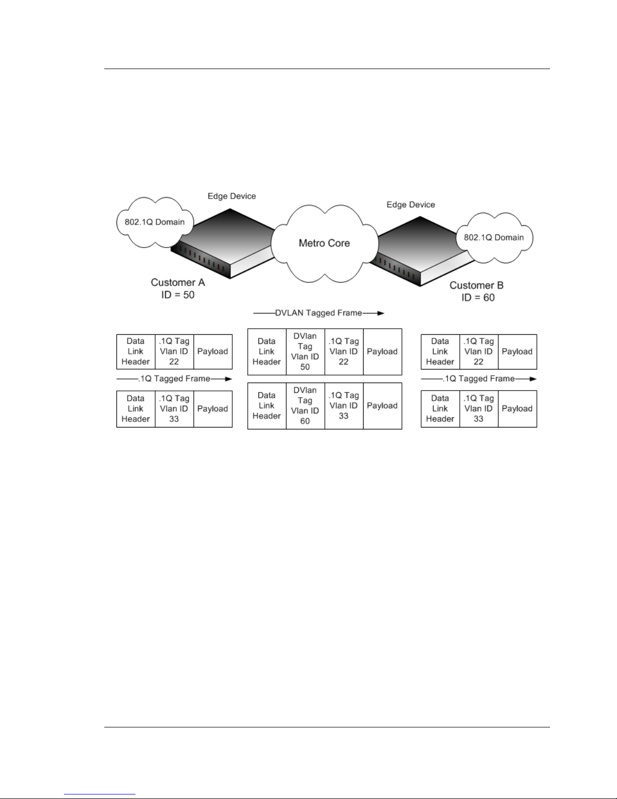
User’s Guide FUJITSU PSWITCH
December/2018 65
has a tag removed.
In Figure 3-3, two customers share the same metro core. The service provider
assigns each customer a unique ID so that the provider can distinguish between
the two customers and apply different rules to each. When the configurable
EtherType is assigned to something different than the 802.1Q (0x8100) EtherType,
it allows the traffic to have added security from misconfiguration while exiting the
metro core.
Figure 3-3: Double VLAN
3.1.2.7.9. Private VLANs
The Private VLANs feature separates a regular VLAN domain into two or more
subdomains. Each subdomain is defined (or represented) by a primary VLAN and a
secondary VLAN. A private VLAN can have multiple VLAN pairs with each pair
identifying a subdomain.
3.1.2.7.10. GARP (Generic Attribute Registration Protocol)
GARP is a protocol that provides a generic framework to register and de-register
attribute value. GARP allows devices to register membership in VLANs (by using
GVRP) or multicast groups (by using GMRP). This feature only support on physical
port interface and LAG.
Page 66

FUJITSU PSWITCH User’s Guide
66 December/2018
3.1.2.7.11. GVRP (GARP VLAN Registration Protocol)
GVRP is a protocol that defines that a GARP Application provides the VLAN
registration service. GVRP-enabled switches exchange VLAN configuration
information, which allows GVRP to provide dynamic VLAN configuration. This is
achieved by using GARP to propagate VLAN ID attributes. This feature only support
on physical port interface and LAG.
3.1.2.7.12. GMRP (GARP Multicast Registration Protocol)
GMRP is a protocol that defines that a GARP Application provides the group
membership registration service. Like IGMP snooping, GMRP helps control the
flooding of multicast packets. GMRP-enabled switches dynamically register and
de-register group membership information with the MAC networking devices
attached to the same segment. GMRP also allows group membership information
to propagate across all networking devices. This is achieved by using GARP to
propagate attributes. This feature only support on physical port interface and LAG.
3.1.2.7.13. MRP (Multicast Registration Protocol)
MRP replaces the Generic Attribute Registration Protocol (GARP) functionality. MRP
is a protocol that provides a generic framework to register and de-register attribute
value. MRP allows devices to register membership in VLANs (by using MVRP) or
MAC address (by using MMRP). This feature only support on physical port interface
and LAG.
3.1.2.7.14. MVRP (Multiple VLAN Registration Protocol)
MVRP replaces the GARP VLAN Registration Protocol (GVRP) functionality. MVRP is a
protocol that defines that a MRP Application provides the VLAN registration service.
MVRP-enabled switches exchange VLAN configuration information, which allows
MVRP to provide dynamic VLAN configuration. This is achieved by using MRP to
propagate VLAN ID attributes. This feature only support on physical port interface
and LAG.
3.1.2.7.15. MMRP (Multiple MAC Registration Protocol)
MMRP replaces the GARP Multicast Registration Protocol (GMRP) functionality.
Page 67

User’s Guide FUJITSU PSWITCH
December/2018 67
MMRP is a protocol that defines that a MRP Application provides the group
membership or individual MAC registration service. Like IGMP snooping, MMRP
helps control the flooding of multicast packets. MMRP-enabled switches
dynamically register and de-register group membership information with the MAC
networking devices attached to the same segment. MMRP also allows group
membership information or individual MAC information to propagate across all
networking devices. This is achieved by using MRP to propagate attributes. This
feature only support on physical port interface and LAG.
3.1.2.8. STP (Spanning Tree Protocol)
Spanning Tree Protocol (STP) is a layer 2 protocol that provides a tree topology for
switches on a bridged LAN. STP allows a network to have redundant paths without
the risk of network loops. STP uses the spanning-tree algorithm to provide a single
path between end stations on a network.
The switches (bridges) that participate in the spanning tree elect a switch to be the
root bridge for the spanning tree. The root bridge is the switch with the lowest
bridge ID, which is computed from the unique identifier of the bridge and its
configurable priority number. When two switches have an equal bridge ID value,
the switch with the lowest MAC address is the root bridge.
After the root bridge is elected, each switch finds the lowest-cost path to the root
bridge. The port that connects the switch to the lowest-cost path is the root port on
the switch. The switches in the spanning tree also determine which ports have the
lowest-path cost for each segment. These ports are the designated ports. Only the
root ports and designated ports are placed in a forwarding state to send and
receive traffic. All other ports are put into a blocked state to prevent redundant
paths that might cause loops.
To determine the root path costs and maintain topology information, switches that
participate in the spanning tree use Bridge Protocol Data Units (BPDUs) to
exchange information.
3.1.2.8.1. STP (Spanning Tree Protocol)
Spanning Tree Protocol (IEEE 802.1D) is a standard requirement of Layer 2 switches
that allows bridges to automatically prevent and resolve L2 forwarding loops. The
STP feature supports a variety of per-port settings including path cost, priority
settings, Port Fast mode, STP Root Guard, Loop Guard, TCN Guard, and Auto Edge.
These settings are also configurable per-LAG.
Page 68

FUJITSU PSWITCH User’s Guide
68 December/2018
3.1.2.8.2. RSTP (Rapid Spanning Tree Protocol)
Rapid Spanning Tree Protocol (RSTP) detects and uses network topologies to
enable faster spanning tree convergence after a topology change, without creating
forwarding loops. The port settings supported by STP are also supported by RSTP.
3.1.2.8.3. MSTP (Multiple Spanning Tree Protocol)
Multiple Spanning Tree (MSTP) operation maps VLANs to spanning tree instances.
Packets assigned to various VLANs are transmitted along different paths within
MSTP Regions (MST Regions). Regions are one or more interconnected MSTP
bridges with identical MSTP settings. The MSTP standard lets administrators assign
VLAN traffic to unique paths.
3.1.2.8.4. MSTP in the Network
In the following diagram of a small 802.1D bridged network, STP is necessary to
create an environment with full connectivity and without loops.
Figure 3-4: STP in a Small Bridged Network
Assume that Switch A is elected to be the Root Bridge, and Port 1 on Switch B and
Switch C are calculated to be the root ports for those bridges, Port 2 on Switch B
and Switch C would be placed into the Blocking state. This creates a loop-free
topology. End stations in VLAN 10 can talk to other devices in VLAN 10, and end
Page 69
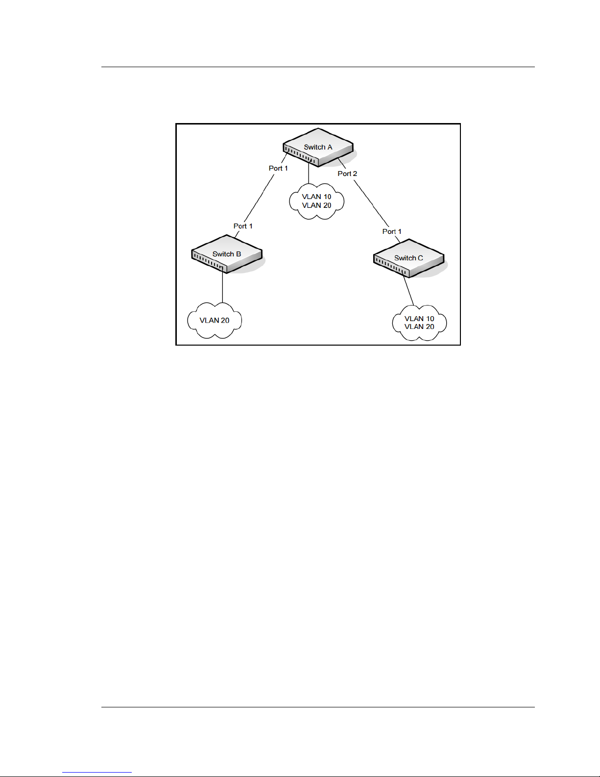
User’s Guide FUJITSU PSWITCH
December/2018 69
stations in VLAN 20 have a single path to communicate with other VLAN 20
devices.
The following Figure 3-5 shows the logical single STP network topology.
Figure 3-5: Single STP Topology
For VLAN 10 this single STP topology is fine and presents no limitations or
inefficiencies. On the other hand, VLAN 20's traffic pattern is inefficient. All frames
from Switch B will have to traverse a path through Switch A before arriving at
Switch C. If the Port 2 on Switch B and Switch C could be used, these inefficiencies
could be eliminated. MSTP does just that, by allowing the configuration of MSTIs
based upon a VLAN or groups of VLANs. In this simple case, VLAN 10 could be
associated with Multiple Spanning Tree Instance (MSTI)1 with an active topology
similar to Figure 3-5 and VLAN 20 could be associated with MSTI 2 where Port 1 on
both Switch A and Switch B begin discarding and all others forwarding. This simple
modification creates an active topology with a better distribution of network traffic
and an increase in available bandwidth.
Page 70
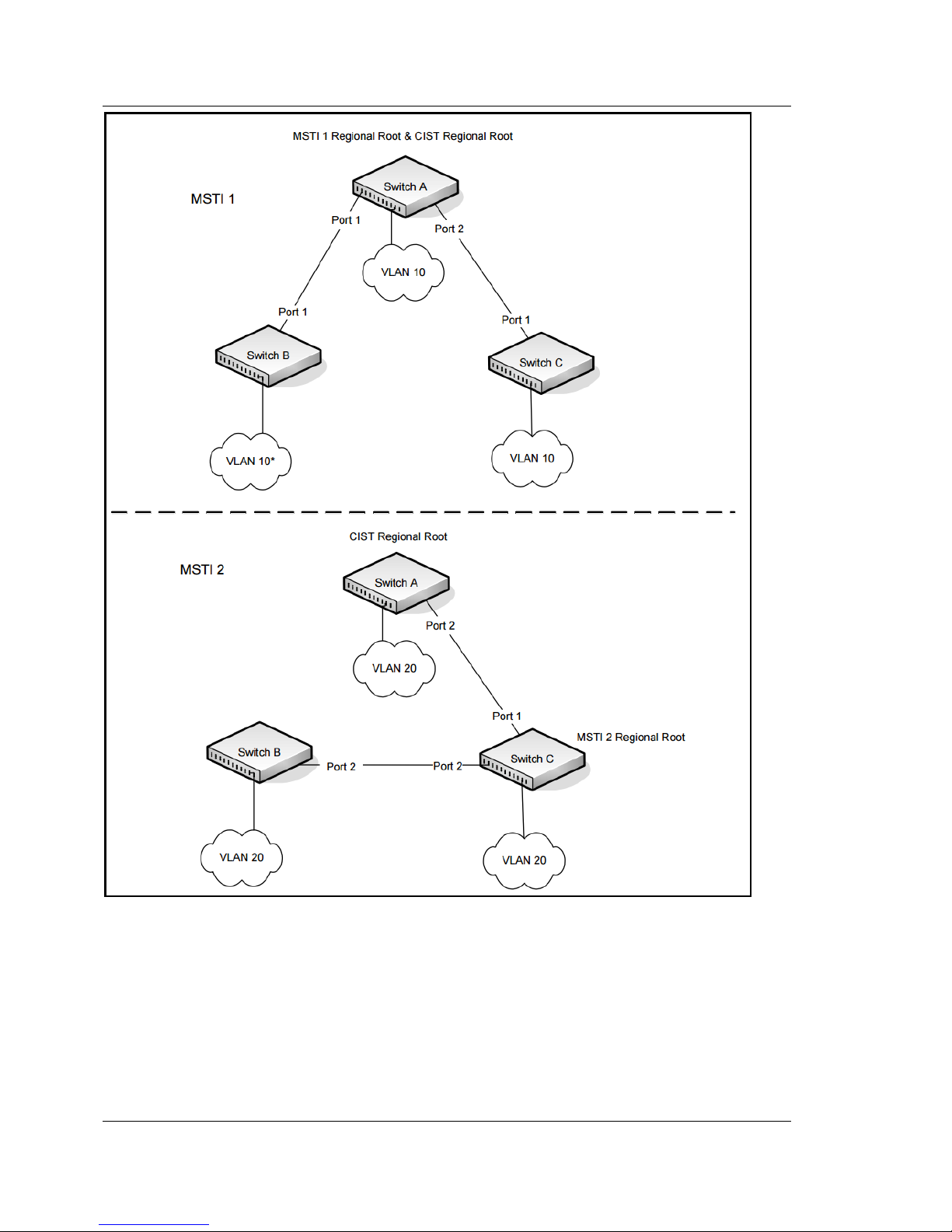
FUJITSU PSWITCH User’s Guide
70 December/2018
Figure 3-6: Logical MSTP Environment
For MSTP to correctly establish the different MSTIs as above, some additional
changes are required. For example, the configuration would have to be the same
on each and every bridge. That means that Switch B would have to add VLAN 10 to
its list of supported VLANs (shown in Figure 3-6 with a *). This is necessary with
MSTP to allow the formation of Regions made up of all switches that exchange the
same MST Configuration Identifier. It is within only these MST Regions that
multiple instances can exist. It will also allow the election of Regional Root Bridges
Page 71

User’s Guide FUJITSU PSWITCH
December/2018 71
for each instance. One common and internal spanning tree (CIST) Regional Root for
the CIST and an MSTI Regional Root Bridge per instance will enable the possibility
of alternate paths through each Region. Above Switch A is elected as both the MSTI
1 Regional Root and the CIST Regional Root Bridge, and after adjusting the Bridge
Priority on Switch C in MSTI 2, it would be elected as the MSTI 2 Regional Root.
To further illustrate the full connectivity in an MSTP active topology, the following
rules apply:
1. Each Bridge or LAN is in only one Region.
2. Every frame is associated with only one VID.
3. Frames are allocated either to the IST or MSTI within any given Region.
4. The internal spanning tree (IST) and each MSTI provides full and simple
connectivity between all LANs and Bridges in a Region.
5. All Bridges within a Region reach a consistent agreement as to which ports
interconnect that Region to a different Region and label those as Boundary
Ports.
6. At the Boundary Ports, frames allocated to the CIST or MSTIs are forwarded or
not forwarded alike.
7. The CIST provides full and simple connectivity between all LANs and Bridges in
the network.
3.1.2.8.5. Classic STP, Multiple STP, and Rapid STP
Classic STP provides a single path between end stations, avoiding and eliminating
loops. Multiple Spanning Tree Protocol(MSTP) is specified in IEEE 802.1s and
supports multiple instances of Spanning Tree to efficiently channel VLAN traffic
over different interfaces. Each instance of the Spanning Tree behaves in the
manner specified in IEEE 802.1w, Rapid Spanning Tree (RSTP), with slight
modifications in the working but not the end effect (chief among the effects, is the
rapid transitioning of the port to Forwarding).
The difference between the RSTP and the traditional STP (IEEE 802.1D) is the
ability to configure and recognize full-duplex connectivity and ports which are
connected to end stations, resulting in rapid transitioning of the port to the
Forwarding state and the suppression of Topology Change Notifications.
MSTP is compatible to both RSTP and STP. It behaves appropriately to STP and RSTP
bridges. A MSTP bridge can be configured to behave entirely as a RSTP bridge or a
STP bridge.
Page 72

FUJITSU PSWITCH User’s Guide
72 December/2018
3.1.2.8.6. Edge Port
The Edge Port feature reduces the STP convergence time by allowing ports that are
connected to end devices (such as a desktop computer, printer, or file server) to
transition to the forwarding state without going through the listening and learning
states.
3.1.2.8.7. BPDU (Bridge Protocol Data Unit) Guard
The STP BPDU guard allows network administrator to enforce the STP domain
borders and keep the active topology be consistent and predictable. The switches
behind the edge ports that have STP BPDU guard enabled are not able to influence
the overall STP topology. At the reception of BPDUs, the BPDU guard operation
disables the port that is configured with this option and transitions the port into
disable state. This would lead to administrative disable of the port.
3.1.2.8.8. Loop Guard
The Loop Guard feature is an enhancement of the Multiple Spanning Tree Protocol.
Loop guard protects a network from forwarding loops induced by BPDU packet loss.
The reasons for failing to receive packets are numerous, including heavy traffic,
software problems, incorrect configuration, and unidirectional link failure. It can be
configured to prevent a blocked port from transitioning to the forwarding state
when the port stops receiving BPDUs for some reason (such as a unidirectional link
failure). When a non-designated port no longer receives BPDUs, the spanning-tree
algorithm considers that this link is loop free and begins transitioning the link from
blocking to forwarding. Once in forwarding state, the link may create a loop in the
network.
Enabling loop guard prevents such accidental loops. When a port is no longer
receiving BPDUs and the max age timer expires; the port is moved to a
loop-inconsistent blocking state. In the loop-inconsistent blocking state, traffic is
not forwarded so the port behaves as if it is in the blocking state. The port will
remain in this state until it receives a BPDU. It will then transition through the
normal spanning tree states based on the information in the received BPDU.
Loop Guard should be configured only on non-designated ports. These
include ports in alternate or backup roles. Root ports and designated ports
should not have loop guard enabled so that they can forward traffic
I
Page 73

User’s Guide FUJITSU PSWITCH
December/2018 73
3.1.2.8.9. Root Guard
Enabling root guard on a port ensures that the port does not become a root port or
a blocked port. When a switch is elected as the root bridge, all ports are designated
ports unless two or more ports of the root bridge are connected together. If the
switch receives superior STP BPDUs on a root-guard enabled port, the root guard
feature moves this port to a root-inconsistent STP state, which is effectively equal
to a listening state. No traffic is forwarded across this port. In this way, the root
guard feature enforces the position of the root bridge.
When the STP mode is MSTP, the port may be a designated port in one MSTI and an
alternate port in the CIST, etc. Root guard is a per-port (not a per-port per instance
command) configuration, so all the MSTP instances this port participates in should
not be in a root role.
3.1.2.8.10. BPDU Filtering
STP BPDU filtering applies to all operational edge ports. Edge Port in an
operational state is supposed to be connected to hosts that typically drop BPDUs. If
an operational edge port receives a BPDU, it immediately loses its operational
status. In that case, if BPDU filtering is enabled on this port then it drops the
BPDUs received on this port.
Ports that have the Edge Port feature enabled continue to transmit BPDUs. The
BPDU filtering feature prevents ports configured as edge ports from sending
BPDUs.
If BPDU filtering is configured globally on the switch, the feature is automatically
enabled on all operational ports where the Edge Port feature is enabled. These
ports are typically connected to hosts that drop BPDUs. However, if an operational
edge port receives a BPDU, the BPDU filtering feature disables the Edge Port
feature and allows the port to participate in the spanning-tree calculation.
Enabling BPDU filtering on a specific port prevents the port from sending BPDUs
and allows the port to drop any BPDUs it receives.
3.1.2.8.11. BPDU Flooding
STP BPDU flooding feature applies to the STP disabled switch. To enable BPDU
flooding on a port, STP should be disabled on the switch administratively. When
this feature is enabled on the switch, it floods all the ports with the BPDU flood
feature enabled on it. It only works on STP, RSTP or MSTP mode.
Page 74

FUJITSU PSWITCH User’s Guide
74 December/2018
3.1.2.8.12. PVRSTP and PVSTP
PVRSTP is the IEEE 802.1w (RSTP) standard implemented per VLAN. A single
instance of rapid spanning tree (RSTP) runs on each configured VLAN. Each RSTP
instance on a VLAN has a root switch. PVSTP is the IEEE 802.1D (STP) standard
implemented per VLAN.
In other words, with PVSTP/PVRSTP, each configured VLAN runs an independent
instance of PVST/PRVST. Each PVSTP/PVRSTP instance elects a root bridge
independent of the other. This means there are as many root bridges in the region
as there are VLANs configured for PVSTP/PVRSTP.
The difference between STP and PVSTP/PVRSTP is primarily in the way the protocol
maps spanning tree instances to VLANs: PVSTP/PVRSTP creates a spanning tree
instance for every VLAN, whereas STP maps all VLANs to one instance.
PVSTP is equivalent to the Cisco PVST+ protocol, and the two protocols can
interoperate. Similarly, PVRSTP is equivalent to Cisco's RPVST+, and these two
protocols can interoperate.
Enabling PVSTP or PVRSTP on a switch disables other spanning tree modes on the
switch.
The switch running PVSTP/PVRSTP transmits IEEE spanning tree BPDUs along with
SSTP BPDUs. The SSTP BPDUs are transmitted as untagged packets on an access or
native VLAN and transmitted as tagged packets on other VLANs.
If the switch running PVSTP/PVRSTP receives an IEEE spanning tree BPDU, then the
switch will include the BPDU in an access VLAN or native VLAN instance.
PVSTP/PVRSTP behavior is as follows:
Access Ports — If the port is configured as access port, then the port sends IEEE
spanning tree BPDUs. For an access port, normal IEEE BPDUs will be received and
sent, though PVSTP or PVRSTP is enabled on the switch. BPDUs received on the
access port will be associated with the CST instance.
Trunk Ports —If the port is configured as a trunk port, then the port sends IEEE
spanning tree BPDUs and SSTP BPDUs on the native VLAN. For other VLANs, the
port transmits SSTP BPDUs as tagged packets with the respective VLANs. If the
trunk port receives IEEE spanning tree BPDUs, then the received BPDUs are
consumed and processed by the instance that is mapped to the native VLAN. The
SSTP BPDUs are processed by instances to which the respective VLANs are mapped.
If the native VLAN on an IEEE 802.1Q trunk is VLAN 1:
Page 75

User’s Guide FUJITSU PSWITCH
December/2018 75
VLAN 1 STP BPDUs are sent to the IEEE STP MAC address (0180.c200.0000),
untagged.
VLAN 1 STP BPDUs are also sent to the SSTP MAC address, untagged.
Non-VLAN 1 STP BPDUs are sent to the SSTP MAC address (also called the Shared
Spanning Tree Protocol [SSTP] MAC address, 0100.0ccc.cccd), tagged with a
corresponding IEEE 802.1Q VLAN tag.
If the native VLAN on an IEEE 802.1Q trunk is not VLAN 1:
VLAN 1 STP BPDUs are sent to the SSTP MAC address, tagged with a
corresponding IEEE 802.1Q VLAN tag.
VLAN 1 STP BPDUs are also sent to the IEEE STP MAC address on the Native VLAN
of the IEEE 802.1Q trunk, untagged.
Non-VLAN 1 STP BPDUs are sent to the SSTP MAC address, tagged with a
corresponding IEEE 802.1Q VLAN tag
If the switch that is running a standard IEEE spanning tree protocol (STP, RSTP, or
MSTP), and it receives the SSTP format BPDUs, the switch does not treat them as
standard BPDUs. Hence, the received SSTP-formatted BPDUs are flooded on all the
ports of the corresponding VLAN. The SSTP BPDUs are multicast over the region.
The interoperation between a switch that runs a standard IEEE spanning tree
protocol and a switch that runs PVSTP/PVRSTP is achieved using CIST. In other words,
to communicate with each other, a switch running the standard IEEE spanning tree
protocol uses its CIST, and a switch running PVSTP/PVRSTP uses an access VLAN or
native VLAN instance.
3.1.2.8.13. STP Fast-Uplink
The PVSTP/PVRSTP FastUplink feature is used for quick selection of a port with the
lowest cost when the root port fails. In other words, the FastUplink feature is used
to reduce convergence time when a link fails. This feature is similar to Cisco’s
UplinkFast feature. When the primary link fails, FastUplink creates an alternate
path immediately. Since the ports that apply FastUplink do not have to wait for
normal convergence time, this will speed up the transition from the failed primary
link to the backup link (the port in a blocking state).
3.1.2.9. Loop Protection
Loop protection is used in LAN to detect any loop and then protect against it. The
loop is detected by sending out Loop Detect Frame (LDF) at each port and to see
Page 76

FUJITSU PSWITCH User’s Guide
76 December/2018
whether we receive those sent LDFs. If a loop is detected on a physical port or LAG
interface, it means a LDF which was sent from the switch is received by itself; some
port(s) will be blocked to cut the detected loop for a period of time, and recovery to
normal when loop cases disappear.
To enhance the loop protection efficiency, we will reserve a dedicated buffer queue
to handle LDF packets. This feature can ensure that our mechanism can work in
extreme network environment.
3.1.2.10. Link Dependency (Link down relay and Backup port)
Link dependency allows the link status of specified ports to be dependent on the
link status of other ports. Consequently, if a port that is depended on by other ports
loses link, the dependent ports are inactive (Link Down Relay) or active (Backup
Port) so that the dependent ports links are brought down or up respectively.
User can form a link dependency group by upstream, downstream, and group
action. Upstream/Downstream is a group of interfaces, the interface could be a
physical port or a port-channel.
When group action is DOWN (Link Down Relay), behavior of upstream/downstream
will like below:
When all upstream ports link down, downstream ports will become inactive -
When one of upstream port link up, downstream ports will become active -
When group action is UP (Backup Port), behavior of upstream/downstream will like
below:
When all upstream ports link down, downstream ports will become active -
When one of upstream port link up, downstream ports will become inactive -
Active/inactive is different from admin enabled/disabled. If a port is admin enabled,
an inactive setting will cause the port link down. If one port is admin disabled,
whether active or inactive setting cannot change the link status. Group status can
control the link dependency work or not. If some ports link down or link up by link
dependency rules, disable the group will recover the port status to original.
Link dependency has a few limitations:
This function is provided in normal mode only. (not in EHM mode)
Upstream/Downstream supports physical port and port-channel, but not
port-channel member.
Each port (physical port/ port-channel) can only participate in one group, and it
cannot exist in both upstream and downstream at the same time
Page 77

User’s Guide FUJITSU PSWITCH
December/2018 77
Port-channel can’t be modified and deleted if it exists in any link dependency
group
Normal port can’t be added to any port-channel if it exists in link dependency
group
3.1.2.10.1. FDB Update
When an upstream port is link down, entries learned by link down port in
Forwarding Database (FDB) will be copied and modified, and then assign to
downstream port. This action also applies to downstream port when upstream port
is link up. Furthermore, this feature also send some dummy Ethernet frames from
backup port to notify its network. The Ethernet frame only contains source MAC
address, which is a MAC address of a device learned from other interfaces except
interfaces that participated in the group, and destination MAC address with
broadcast address (FF:FF:FF:FF:FF:FF).
This feature has two limitations:
This feature only works with Backup Port group. Configuring this feature on Link
Down Relay group won’t take effect and considered as disabled.
This feature only supports one-to-one Backup Port group. Configuring this
feature on the group that has more than one port in upstream or more than one
port in downstream won’t take effect and considered as disabled.
3.1.2.10.2. Upstream threshold
If the link down ports of upstream reaches the threshold, i.e. link up upstream
ports are less than 11%, all upstream ports will be shut down. To restore the
upstream ports, users need to issue “no shutdown” to each upstream port in the
link dependency group. This feature has a limitation:
Upstream threshold only works with Backup Port group. Configuring this feature
on Link Down Relay group won’t take effect and considered as disabled.
3.1.2.11. Port Mirroring
Port mirroring monitors and mirrors network traffic by forwarding copies of
incoming and outgoing packets from up to four source ports to a monitoring port.
The switch supports up to four monitor sessions. Port mirroring, RSPAN, and VLAN
mirroring can be configured at the same time on the switch using different
sessions IDs and in any combinations. Any two sessions cannot be identical.
Page 78

FUJITSU PSWITCH User’s Guide
78 December/2018
Multiple mirroring sessions are supported for all types of mirroring.
A given interface can be used as a source interface for different sessions. For
example a mirroring session can be created with source interface as port A and
destination interface as port B. Another session can be created with source
interface as port A and destination interface as port C. An interface cannot be
configured as a destination interface for more than one session.
Traffic to and from the CPU can also be mirrored by specifying the CPU as the source
interface.
An IP/MAC access-list can be attached to any mirroring session or to all sessions at
the same time.
3.1.2.11.1. RSPAN (Remote Switched Port Analyzer)
Along with the physical source ports, the network traffic received/transmitted on a
VLAN can be monitored. A port mirroring session is operationally active if and only
if both a destination (probe) port and at least one source port or VLAN is
configured. If neither is true, the session is inactive. The switch supports remote
port mirroring and VLAN mirroring. Traffic from/to all the physical ports which are
members of that particular VLAN is mirrored.
The source for a port mirroring session can be either physical ports or VLAN.
Up to four RSPAN sessions can be configured on the switch and up to four RSPAN
VLANs are supported. An RSPAN VLAN cannot be configured for more than one
session at the same time. To configure four RSPAN mirroring sessions, you must
configure four RSPAN VLANs.
3.1.2.12. LLDP (Link Layer Discovery Protocol)
The IEEE 802.1AB standard defines the Link Layer Discovery Protocol (LLDP). The
protocol allows stations residing on an 802 LAN to advertise major capabilities,
physical descriptions, and management information to physically adjacent devices,
allowing a network management system (NMS) to access and display this
information.
The standard is designed to be extensible, providing for the optional exchange of
organizational specific information and data related to other IEEE standards. The
initial implementation supports only the required basic management set of type
length values (TLVs).
I
Page 79

User’s Guide FUJITSU PSWITCH
December/2018 79
The LLDP component transmit and receive functions can be enabled/disabled
separately per physical port. By default, both transmit and receive functions are
disabled on all ports.
Both local and remote data may be displayed by the user interface and retrieved
using SNMP as defined in the LLDP MIB definitions.
3.1.2.13. UDLD (Unidirectional Link Detection)
The UDLD feature detects unidirectional links to physical ports. UDLD must be
enabled on the both sides of the link in order to detect a unidirectional link. The
UDLD protocol operates by exchanging packets containing information about
neighboring devices. The purpose of the UDLD feature is to detect and avoid
unidirectional links. A unidirectional link is a forwarding anomaly in a Layer 2
communication channel in which a bidirectional link stops passing traffic in one
direction.
3.1.2.13.1. UDLD Modes
The UDLD supports two modes: normal and aggressive.
In normal mode, a port's state is classified as undetermined if an anomaly exists.
An anomaly might be the absence of its own information in received UDLD
messages or the failure to receive UDLD messages. An undetermined state has no
effect on the operation of the port. The port is not disabled and continues
operating.
When operating in UDLD normal mode, a port will be put into a disabled state
(D-Disable) only in the following situations:
The UDLD PDU received from a partner does not have its own details (echo).
When there is a loopback, and information sent out on a port is received back
exactly as it was sent.
When operating in UDLD aggressive mode, a port is put into a disabled state for
the same reasons that it occurs in normal mode. Additionally, a port in UDLD
aggressive mode can be disabled if the port does not receive any UDLD echo
packets even after bidirectional connection was established. If a bidirectional link
is established, and packets suddenly stop coming from partner device, the UDLD
aggressive-mode port assumes that link has become unidirectional.
Page 80
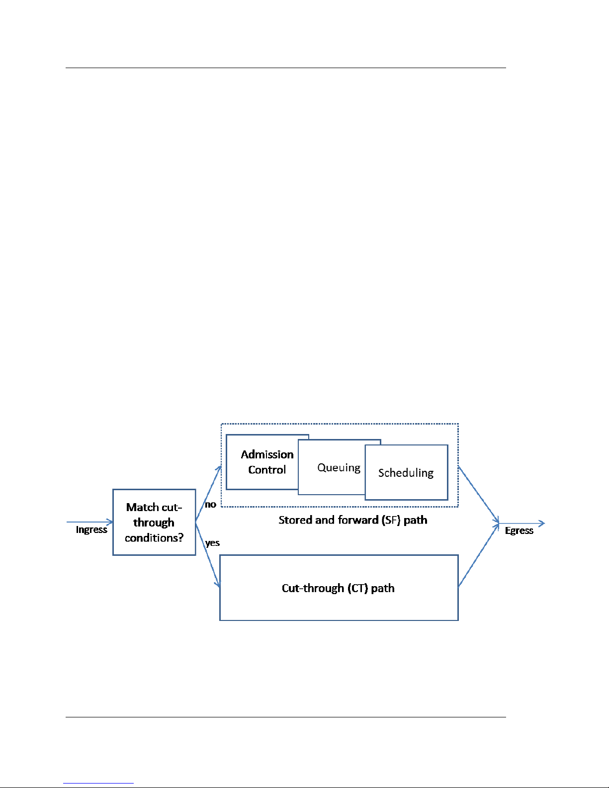
FUJITSU PSWITCH User’s Guide
80 December/2018
3.1.2.13.2. UDLD and LAG Interfaces
UDLD is supported on individual physical ports that are members of a LAG. If any of
the aggregated links becomes unidirectional, UDLD detects it and disables the
individual link, but not the entire LAG. This improves the fault tolerance of the LAG.
3.1.2.14. Cut-Through Mode
Switch supports both store-and-forward (SF) and cut-through (CT) modes. In SF
mode, an entire incoming packet is written into the buffer before it is evaluated for
acceptance. The packet is held in the buffer until the scheduler selects that
particular egress port’s queue. In CT mode, the packet is scheduled through the
cut-through path before it has been completely received. SF mode is used in most
applications while CT mode is used in latency-sensitive applications. The primary
benefit of CT mode, compared with SF, is low latency.
While CT mode is enabled, CT eligibility is evaluated on every incoming packet,
depending on its source, destination, and other existing conditions based on the
flow. There are conditions that must be checked before allowing packets to be
marked for cut-through. If a port is in CT mode but CT mode evaluation fails, the
packet is treated as an SF packet and the port automatically reverts to CT mode
again when the CT packet evaluation or check test passes.
Figure 3-7: Cut-Through Mode
In CT mode, the control path does not pass through the Admission, Queuing, or
Scheduling blocks as it does in SF mode. Packets are not enqueued or scheduled,
and not stored in the packet buffer. Packet transmission starts for that egress port
Page 81
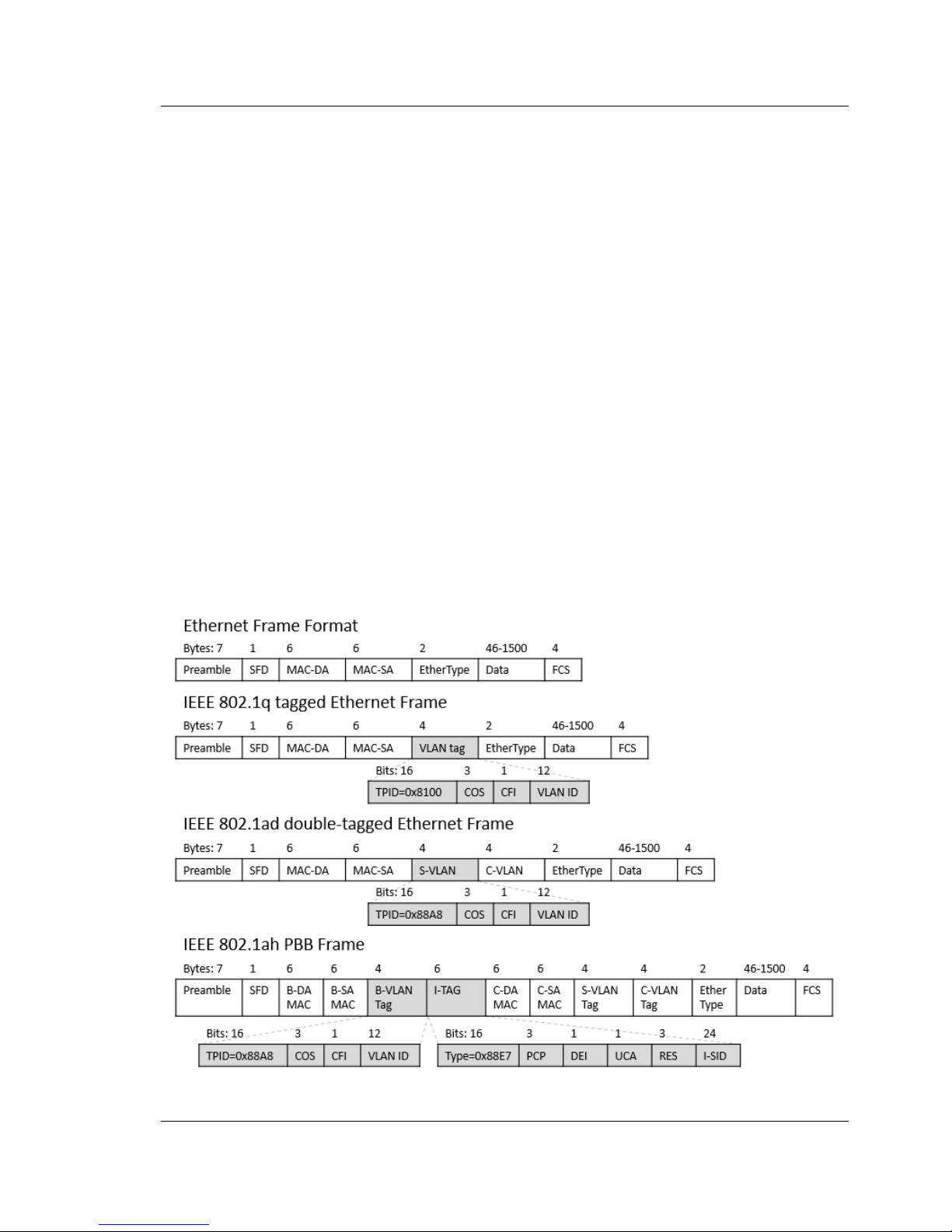
User’s Guide FUJITSU PSWITCH
December/2018 81
immediately on the next available time.
3.1.2.15. Provider Backbone Bridging (IEEE 802.1ah)
Provider Backbone Bridging (PBB), also called MAC-in-MAC, supports larger
networks by encapsulating frames in the network. By hiding the MAC addresses, it
enables scalability of the backbone network.
The PBB of this product supports the followings:
IB Component
Customer network port matching S tag, C tag, or any frames
Point-to-point connection
One backbone MAC address
Since multicast is not supported, PBB networks can not have more than three BEBs
that use the same I-SID.
3.1.2.15.1. Frame Encapsulation
A comparison between each type of Ethernet frames:
Figure 3-8: Comparison between each type of Ethernet frame
Page 82

FUJITSU PSWITCH User’s Guide
82 December/2018
Please note that the first VLAN tag in a PBB frame does not use TPID 0x8100 in its
VLAN tag. The Device that switches PBB frames must be configured to recognize
the TPID 0x88A8 VLAN tag.
In the backbone network, all customer frames are encapsulated in the backbone
edge bridge (BEB) and forwarded to another BEB device. The device that switches
the PBB frame of the backbone network is the backbone core bridge (BCB). The
way to encapsulate a frame with PBB header is shown below.
Ethernet Frame
Description
B-DA
Destination MAC address of the backbone network
B-SA
Source MAC address of backbone network
B-tag
802.1ad service VLAN tag in the backbone network, TPID 0x88A8
I-tag
802.1ah service identifier tag, TPID 0x88E7
C-DA
Destination MAC address from customer network
C-SA
Source MAC address from customer network
S-tag
802.1ad service VLAN tag, TPID 0x88A8 (optional)
C-tag
802.1q customer VLAN tag, TPID 0x8100 (optional)
Payload
data
Table 3-3: Frame Encapsulation
The B-tag assignment is determined by the I-tag, and the I-tag assignment is
determined by the customer frame received. This product provides several options
for mapping customer frames to service instances.
BCB devices do not need to be PBB compliant. As B-tag has the same TPID as S-tag,
as long as the device supports TPID 0x88A8 VLAN tag transfer, the encapsulated
frame can be handled as Q-in-Q frame and forwarded to the destination. In order
for the device to act as a BCB, the device enables the VMAN as the primary VLAN
tag with the Double VLAN tunneling feature in order for the device to recognize the
B-tag and forward frames correctly.
3.1.2.15.2. I-domain
The I-domain is similar to the I-component described in IEEE 802.1ah. Create a
virtual network in the switch and manage the FDB table on the customer network.
This virtual network is bridged to the B-domain so that it is encapsulated and
forwarded to the backbone network. This domain is assigned a service instance
identifier (I-SID).
This domain also manages a table of C-MAC mappings to B-MAC. Users can set
static entries and decide how to map these C-MACs. Aging time is the same as
filtering database entries. When the table is full, you can not add new entries and
Page 83

User’s Guide FUJITSU PSWITCH
December/2018 83
you must wait for old entries to expire.
When an unknown unicast, multicast, broadcast MAC is received, the frame can be
encapsulated with a specific backbone MAC address. However, this address can not
be multicast or broadcast address. Because of this limitation, a PBB network can
not have more than three BEBs contain the same I-SID.
All interfaces contained in this domain are treated as Customer Network Ports
(CNP). Each CNP can provide the following services:
Port based services:
All received frames are mapped to I-SID. All tags are saved in the frame.
S-Tag Service:
The incoming frame with the set S tag is mapped to the I-SID, and the S tag in
the frame is saved. Multiple tags can be mapped to the same I-SID.
C-Tag Service:
The incoming frame with the set C tag is mapped to the I-SID, and the C tag in
the frame is saved. Multiple tags can be mapped to the same I-SID.
3.1.2.15.3. B-domain
The B-domain is similar to the B-component described in IEEE 802.1ah. This
domain faces the backbone network and learns and transfers PBB frames. When a
PBB frame has a known I-SID by this switch, it is decapsulated and forwarded to
the corresponding I-domain. A B-tag is assigned to this domain.
All interfaces contained in this domain are treated as provider network ports (PNP).
For all interfaces in the B-domain, the MTU (Maximum Transmission Unit) must be
set 22 bytes larger than the MTU of the I-domain interface.
For example:
Figure 3-9: I-domain and B-domain MTU configuration example
3.1.2.15.4. Traffic Engineering
Traffic engineering enables traffic engineering mode to provide more predictable
network traffic. There is no loop prevention in the traffic engineering environment.
Instead, this function discards all non-unicast and unknown unicast frames on the
Page 84

FUJITSU PSWITCH User’s Guide
84 December/2018
B-domain interface that faces the backbone network. It also disables both MAC
learning and Spanning Tree Protocol. For users to enable this feature, SPBM must
be disabled.
This equipment can not operate as a BCB in the traffic engineering network. Only
point-to-point BEB connection is supported.
3.1.2.16. Shortest Path Bridging MAC (IEEE 802.1aq)
The shortest path bridging MAC (SPBM) allows multiple shortest path transfers in
mesh Ethernet network context using multiple equal cost paths. It is designed to
replace STP in the backbone network. SPBM does not put the port in the discard
state, it uses all available ports and uses the same filtering database as the Layer 3
protocol update routing table.
The SPBM needs to be deployed in the provider backbone bridge network. The
results calculated by IS-IS apply to B-VLAN filtering database. Broadcast, unknown
unicast and multicast are not allowed on this network. In order to enable this
function, PBB-TE must be disabled.
Since multicasting within the SPBM network is not supported, the SPBM network
can not have more than two BEBs that use the same I-SID.
3.1.2.16.1. IS-IS (Intermediate System to Intermediate System)
Intermediate System to Intermediate System (IS-IS) is a link-state routing protocol
used for SPB. IS-IS has been extended to carry the necessary Ethernet address,
VLAN, and service membership information introduced by the SPB.
When used for SPB, there is no IP dependency on IS-IS. IS-IS also supports
multi-topology (MT) and logical instances for easy virtualization of link-state
protocols.
3.1.2.16.2. SPB extension
The IS-IS extended for SPB is called ISIS-SPB. SPB extensions are additional to IS-IS
and do not preclude other IS-IS protocols that are used at the same time. ISIS-SPB
supports only point-to-point links.
ISIS-SPB updates the link-state database using the regular IS-IS procedure. IS-IS
communicates between ISIS-SPB switches using SPB Hello PDUs and link state
PDUs (LSPs).
Page 85
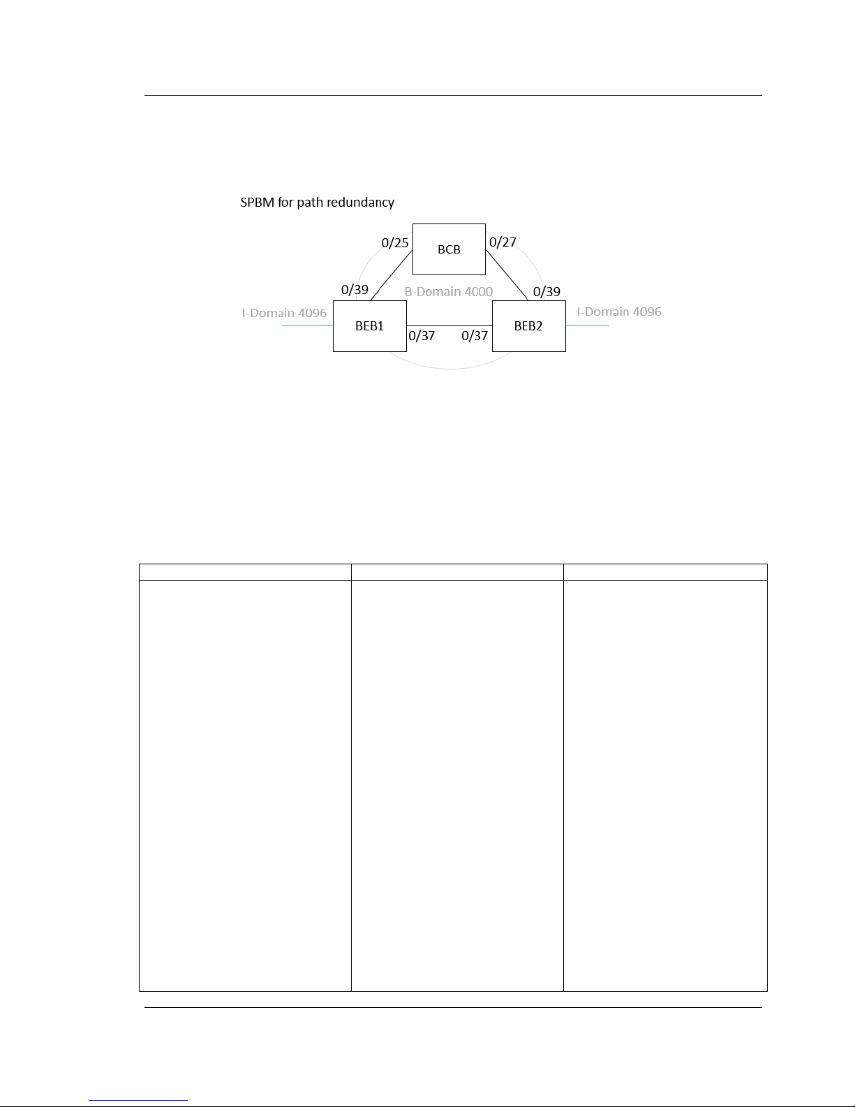
User’s Guide FUJITSU PSWITCH
December/2018 85
Spanning tree protocol is disabled while SPBM is running. VLANs used by SPBM are
loop free, but VLANs not used by SPBM may cause loops in the topology.
Here is an example of using SPBM for path redundancy.
Figure 3-10: SPBM for path redundancy
In Figure 3-10, the link between BEB 1 and BEB 2 has the lowest cost. SPBM uses
this link to forward traffic from I-Domain 4096. When this link goes down, the
SPBM recalculates for topology change and selects another link to the BCB to
forward traffic. In this example, the BCB is configured to pass only VLAN 4000
traffic to prevent loops.
The following is an example setting for each switch.
BEB1
BEB2
BCB
hostname "BEB1"
vlan database
vlan 256,4000
exit
configure
interface 0/37
isis enable
isis spbm
exit
interface 0/39
isis enable
isis spbm
exit
mim backbone-source-mac
00:00:00:11:11:11
mim b-domain 4000
interface 0/37
interface 0/39
exit
mim i-domain 10000
interface 0/1 match dot1ad 256
bridge 4000
flooding-mac
00:00:00:22:22:22
exit
router isis
hostname "BEB2"
vlan database
vlan 256,4000
exit
configure
interface 0/37
isis enable
isis spbm
exit
interface 0/39
isis enable
isis spbm
exit
mim backbone-source-mac
00:00:00:22:22:22
mim b-domain 4000
interface 0/37
interface 0/39
exit
mim i-domain 10000
interface 0/1 match dot1ad 256
bridge 4000
flooding-mac
00:00:00:11:11:11
exit
router isis
hostname "BCB"
vlan database
vlan 4000
exit
configure
dvlan-tunnel ethertype vMAN
primary-tpid
interface 0/25
switchport mode trunk
switchport trunk allowed vlan
4000
isis enable
isis spbm
exit
interface 0/27
switchport mode trunk
switchport trunk allowed vlan
4000
isis enable
isis spbm
exit
router isis
spbm
spbm b-vid 4000 ect 1
enable
exit
Page 86

FUJITSU PSWITCH User’s Guide
86 December/2018
spbm
spbm b-vid 4000 ect 1
enable
exit
exit
spbm
spbm b-vid 4000 ect 1
enable
exit
exit
exit
3.1.2.17. EHM (End Host Mode)
Fujitsu introduced a further operation mode is called End Host Mode (EHM) . This
mode provides a very simple way of establishing connections and administering
the switch.
EHM have following feature:
EHM does not interfere with the customer STP domain nor does it introduce data
loops. It has no STP implemented and also avoids loops inherently with disabled
switching between uplink ports.
EHM does not burden additional effort for LAG deployment. With the new
introduced technology "Pinning", there is no LAG to the upstream (customer)
switch required anymore, but available as an option.
EHM does not burden additional effort for VLAN administration. With "
Automatic VLAN uplink Synchronization " (AVS), VLAN administration is greatly
automated.
These characteristics mean that the switch are very easy and secure for integration
in any data center networking environment. There are just two easy steps to
integrate:
1. Simply connect the switch with the upstream network. No STP, LAG and VLAN
configuration is required.
2. On the switch downlink ports, assign VLANs for the servers (i.e. on the downlink
port only). Assigned VLANs will be automatically synchronized with the
appropriate uplink port (connection to the upstream customer switch).
3.1.2.17.1. Enable EHM
EHM and normal switch mode can coexist at the same time. To enable EHM, users
need to add uplink port(s) and downlink port(s) into a Pin Group. EHM behavior
will start automatically after pin group is formed, and no need to reboot system.
Each port in pin group will follow the EHM behavior, which will be described as
below.
Users should avoid following configurations work together with EHM:
STP (should be disabled on all EHM ports) -
Page 87
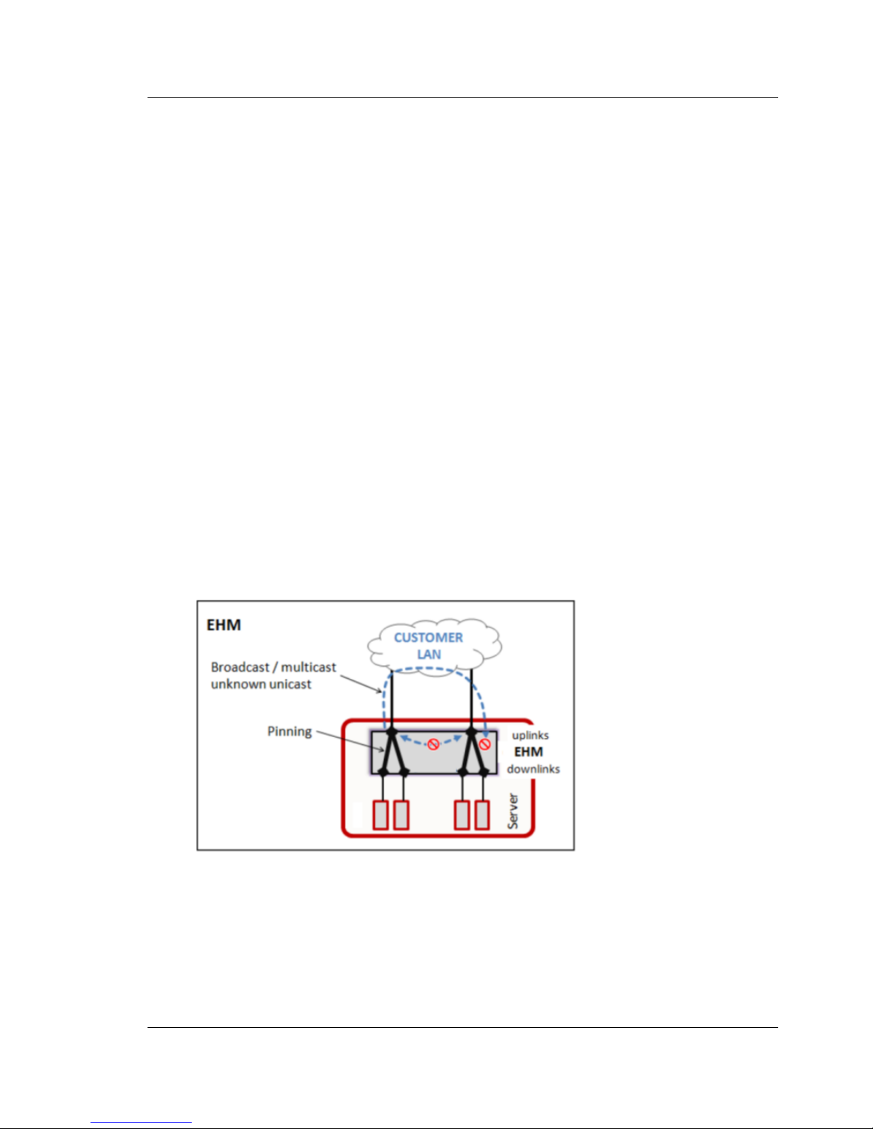
User’s Guide FUJITSU PSWITCH
December/2018 87
Link Dependency -
Loop Protection -
GVRP -
Double VLAN -
L3 routing interface -
IGMP snooping -
Multicast routing -
3.1.2.17.2. Pin Group
In EHM, users can configure Pin Group by manual. A pin group includes uplink port
and down link port. Once pin group is created, pinning process will start
automatically. The Pin Group has following feature:
Traffic cannot pass through between interfaces of EHM and normal switch mode.
Downlink ports are pinned only to uplink ports of the same pin group
Each interfaces can only be part of a single pin group
Packet switching between downlink ports is possible even when pinning is
enabled
Data loops are avoided with disabled switching between uplink ports.
Uplink port will filter traffic from downlink port returning on its uplink ports.
Mac-address learning on uplink ports is disabled.
Figure 3-11: End Host Mode
3.1.2.17.3. Pinning
Pinning is a new feature introduced in EHM. It will automatically pins server ports
(downlink ports) to dedicated uplink ports within the same pin group. That means
Page 88
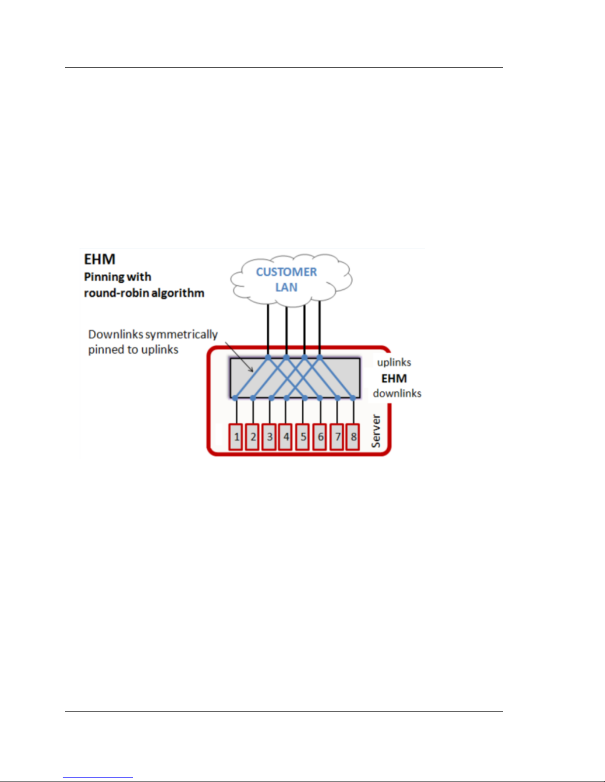
FUJITSU PSWITCH User’s Guide
88 December/2018
all traffic from servers is sent through its dedicated pinned uplink port to the
customer network.
3.1.2.17.4. Pinning process
Within a pin group, downlink ports are pinned to uplink ports automatically with
round-robin algorithm.
Round-robin means, when the first "up" downlink is pinned to an available uplink,
the next "up" downlink is pinned to the next available uplink and so forth; this
leads to a symmetrical allocation of downlink ports to uplink ports.
Figure 3-12: Pinning process
The following conditions must match in order to successfully get a downlink port
pinned to an uplink port:
1. Downlink port and uplink port must have link status "up" and must belong to
the same pin-group.
2. The uplink port must house ALL VLANs of the downlink port.
If the uplink port chosen by the round-robin algorithm does not host all VLANs
configured on the downlink port, pinning process searches for another appropriate
uplink port. If no appropriate uplink port is available, the downlink is not pinned.
In that case, the downlink port status remains "up" but no traffic flow is possible to
any uplink port.
Only uplink ports with the highest priority are used for pinning. Other uplink ports
with a lower priority are never used for pinning. Uplink port priorities:
Page 89

User’s Guide FUJITSU PSWITCH
December/2018 89
LAG > 40GE > 10GE > 1GE > 100MB
3.1.2.17.5. Re-pinning process
Within a pin group, the re-pinning process will re-run whole pinning process. Some
dummy Ethernet frames will be send by the new pinned interface to refresh the
MAC address table of the upstream switch. The Ethernet frame only contains source
MAC address, which are MAC address learned on downlink ports, and destination
MAC address with broadcast address (FF:FF:FF:FF:FF:FF).
The re-pinning process is triggered by the following events:
An uplink port link status change -
An uplink port VLAN configuration change -
3.1.2.17.6. Re-pinning timer
While the first available uplink port gets pinned immediately, if an additional
uplink port changes its state from down to up, re-pinning process waits per default
10 seconds to pin downlink ports to it. This timer is user configurable.
3.1.2.17.7. Link down relay
In a pin group, if there is no uplink port with link status “up”, link down relay
feature will shut down all downlink ports of that pin group.
3.1.2.17.8. Internal network
Within a pin group, internal network is used to realize traffic switching between
downlink ports. If users turn off pinning function on downlink ports, the ports will
join into internal network automatically.
3.1.2.17.9. AVS (Auto VLAN uplink Synchronization)
AVS automatically synchronizes the VLAN configuration of the uplink ports with the
VLAN configuration of the downlink ports. This feature is user configurable. With
AVS, only downlink ports need to be configured with a VLAN id. All remaining VLAN
configuration tasks are automated.
VLAN creation and assignment: A VLAN is automatically created and configured
on the pinned uplink port.
Page 90

FUJITSU PSWITCH User’s Guide
90 December/2018
VLAN pruning: A VLAN is automatically pruned from an uplink port in case it is
not assigned to any of its pinned downlink ports.
VLAN deletion: A VLAN is automatically deleted in case it is not configured on
any downlink port.
These tasks listed above are triggered by the following events:
VLAN configuration change on downlink
Link status change on uplink port
AVS activation
3.1.2.17.10. Pin States
Downlink ports have following possible states:
Pin State
Meaning
Pinned
Downlink port is successfully pinned to an uplink port.
Not pinned
VLAN configuration mismtch: Uplink port does not host all VLANs
configured on the downlink port.
Idle
With link state „down“: Pinning process waits for downlink port
„up“ status.
With link state „up“: Pinning process is waiting for the re-pinning timer
to expire.
Pinning
Pinning in progress
Disable
Pinning is administratively disabled with port command „no
pinning“ (used for internal metwork).
Do not wire uplink port and downlink in a same Pin Group because it may
cause network loop.
When LAG interface is set as uplink and/or downlink in a Pin Group, it is
recommended that each LAG member port is also set as uplink and/or
downlink in the Pin Group.
3.1.3. Multicast
3.1.3.1. IGMP Snooping
Internet Group Management Protocol (IGMP) Snooping is a feature that allows a
switch to forward multicast traffic intelligently on the switch. Multicast IP traffic is
traffic that is destined to a host group. Host groups are identified by class D IP
addresses, which range from 224.0.0.0 to 239.255.255.255. Based on the IGMP
I
I
Page 91

User’s Guide FUJITSU PSWITCH
December/2018 91
query and report messages, the switch forwards traffic only to the ports that
request the multicast traffic. This prevents the switch from broadcasting the traffic
to all ports and possibly affecting network performance.
Special attention should be brought to the IP address range 224.0.0.1 through
224.0.0.255, which is reserved for routing protocols and other low-level topology
discovery or maintenance protocols. For example, the address 224.0.0.1 is the all
hosts address, and 224.0.0.2 indicates all routers on this subnet.
3.1.3.2. MLD snooping
In IPv6, Multicast Listener Discover (MLD) snooping performs functions similar to
IGMP snooping in IPv4. With MLD snooping, IPv6 multicast data is selectively
forwarded to a list of ports that want to receive the data, instead of being flooded
to all ports in a VLAN. This list is constructed by snooping IPv6 multicast control
packets.
The switch can snoop on both MLDv1 and MLDv2 protocol packets and bridge IPv6
multicast data based on destination IPv6 Multicast MAC Addresses. The switch can
be configured to perform MLD Snooping and IGMP Snooping simultaneously.
3.1.3.3. Snooping querier
The IGMP/MLD Snooping Querier is an extension to the IGMP/MLD Snooping feature.
It enhances the switch capability to simulate an IGMP/MLD router in a Layer 2
network, thus removing the need to have an IGMP/MLD Router in a Layer 2
network to collect the Multicast group membership information. The querier
functionality is a small subset of the IGMP/MLD router functionality.
3.1.3.4. MRoutes (Multicast Static Routes)
The IP Multicast Static Route (MRoute) feature allows multicast paths to diverge
from the unicast paths.
3.1.3.5. IGMP (Internet Group Management Protocol) v2/v3
Internet Group Management Protocol (IGMP) is the multicast group membership
discovery protocol used for IPv4 multicast groups. Three versions of IGMP exist.
Versions one and two are widely deployed. Since IGMP is used between end
systems (often desktops) and the multicast router, the version of IGMP required
depends on the end-user operating system being supported. Any implementation
Page 92

FUJITSU PSWITCH User’s Guide
92 December/2018
of IGMP must support all earlier versions.
The following list describes the basic operation of IGMP, common to all versions. A
multicast router can act as both an IGMP host and an IGMP router and as a result
can respond to its own IGMP messages. The software implementation of IGMPv3
supports the multicast router portion of the protocol (that is, not the host portion).
It is backward compatible with IGMPv1 and IGMPv2.
One router periodically broadcasts IGMP Query messages onto the network.
Hosts respond to the Query messages by sending IGMP Report messages
indicating their group memberships.
All routers receive the Report messages and note the memberships of hosts on
the network.
If a router does not receive a Report message for a particular group for a period
of time, the router assumes there are no more members of the group on the
network.
All IGMP messages are raw IP data grams and are sent to multicast group
addresses, with a time to leave (TTL) of 1. Since raw IP does not provide reliable
transport, some messages are sent multiple times to aid reliability.
3.1.3.6. MLD (Multicast Listener Discovery) v1/v2
Multicast Listener Discovery (MLD) protocol enables IPv6 routers to discover the
presence of multicast listeners, the nodes who wish to receive the multicast data
packets on its directly attached interfaces. On IPv6 multicast routers, MLD replaces
the functionality performed by IGMP on IPv4 networks.
MLD discovers which multicast addresses are of interest to its neighboring nodes
and provides this information to the active multicast routing protocol that makes
decisions on the flow of multicast data packets.
The software implementation of MLD v2 supports only the multicast router portion
of the protocol and not the listener portion. It is backward-compatible with MLD v1.
3.1.3.7. DVMRP (Distance Vector Multicast Routing Protocol)
Distance Vector Multicast Routing Protocol (DVMRP) is a dense mode multicast
protocol and is most appropriate for use in networks where bandwidth is relatively
plentiful and there is at least one multicast group member in each subnet. DVMRP
assumes that all hosts are part of a multicast group until it is informed of multicast
group changes. When the dense-mode multicast router is informed of a group
membership change, the multicast delivery tree is pruned. DVMRP uses a
Page 93

User’s Guide FUJITSU PSWITCH
December/2018 93
distributed routing algorithm to build per-source-group multicast trees. It is also
called Broadcast and Prune Multicasting protocol. It dynamically generates
per-source-group multicast trees using Reverse Path Multicasting. Trees are
calculated and updated dynamically to track membership of individual groups.
The DVMRP protocol operates as follows:
1. The first message for any (source, group) pair is forwarded to the entire
multicast network, with respect to the packet’s time-to-live (TTL).
2. TTL restricts the area to be flooded by the message.
3. Any leaf router that does not have members on directly attached subnetworks
sends back prune messages to the upstream router.
4. The branch that transmitted a prune message is deleted from the delivery tree.
DVMRP transmits two types of messages:
Protocol messages:
These include Probe messages, Prune messages, Graft messages and Graft
Acknowledgements, and so on, which are sent as multicast packets. Most
protocol messages are addressed to ALL-DVMRP-ROUTERS.
Routing messages:
These are unicast messages used to exchange routing information. They are
typically sent by a neighboring router when it is restarted, has lost its routing
information, or has come up from a down state. They are also transmitted
when a graft is sent in response to a new member’s subscription to an existing
group, or when a new group is subscribed.
When messages arrive, the reverse path to the source of the message is discovered
by examining the routing table. If the message arrived on the interface that would
be used to transmit the message back to the source, the message is transmitted to
downstream routers. Otherwise, the message is not on the optimal delivery tree, so
the packet is dropped. In this way, loops and duplicates are filtered. DVMRP
discovers its neighbors by periodically sending probe messages with a TTL of one
(1). These probe messages contain the list of neighboring DVMRP routers from
which a probe has been received. With this, a two-way neighbor relationship is
established.
When two different routers are connected to the same multi-access network, there
is a possibility of getting duplicate packets. To avoid getting duplicate packets,
nominate a Designated Forwarder (DF) for each network. The router with the least
metric is the designated forwarder. In case of a tie, the router with the lower IP
address is the designated forwarder. Once a designated forwarder is elected, the
multicast trees are built. If the destination group of a packet exists in the local
database and the router on which the packet arrived is the designated forwarder,
then that interface is added to the downstream interface list.
Page 94

FUJITSU PSWITCH User’s Guide
94 December/2018
The edge routers remove interfaces with no group members from their multicast
trees. If all the downstream interfaces are removed, the router sends a prune
message to its upstream neighbors. Every prune message has a lifetime, after
which the interface is joined back onto the delivery tree. If the unwanted
datagrams still appear, the prune is initiated again. If a host joins a previously
pruned branch of a tree, the DVMRP routers use graft messages to cancel the
previous prunes.
Limitations
This software DVMRP does not support DVMRP tunnels. -
This software supports only the IPv4 version of DVMRP. -
This software DVMRP does not support DMVRP netmask capability. -
3.1.3.8. PIM-DM (Protocol Independent Multicast — Dense Mode)
Protocol Independent Multicast (PIM) protocols are not dependent on any
particular unicast routing protocols to construct forwarding information for
multicast packets, although unicast information is needed for forwarding packets.
The Dense Mode (DM) version of PIM is most appropriate for networks with
relatively plentiful bandwidth and with at least one multicast member in each
subnet.
PIM-DM assumes that all hosts are part of a multicast group and forwards packets
to hosts until informed that group membership has changed. A group membership
change results in the multicast delivery tree being pruned.
The PIM-DM protocol operates as follows:
1. The first message for any (source, group) pair is forwarded to the entire
multicast network, with respect to the time-to-live (TTL) value in the packet.
2. TTL restricts the area flooded by the packet.
3. All leaf routers with no members in a directly attached subnet send prune
messages to the upstream router.
4. Any branch for which a prune message is received is deleted from the delivery
tree.
PIM-DM uses Reverse Path Forwarding (RPF), which is the fundamental concept in
multicast routing that enables routers to correctly forward multicast messages
down the distribution tree. RPF makes use of the existing unicast routing table to
determine the upstream and downstream neighbors and build a source-based
shortest-path distribution tree. A router forwards a multicast message only if the
multicast message is received on the upstream interface. This RPF check helps to
guarantee that the distribution tree is loop-free.
Page 95

User’s Guide FUJITSU PSWITCH
December/2018 95
The multicast messages contain the source and group information so that
downstream routers can build up their multicast forwarding tables. If the source
goes inactive, the tree is torn down. Multicast messages arriving at a router over
the proper receiving interface (that is, the interface that provides the shortest path
back to the source) are forwarded on all downstream interfaces until unnecessary
branches of the tree are explicitly pruned. In addition to the prune messages,
PIM-DM uses graft messages and assert messages. Graft messages are used when
a new host wants to join a group, and assert messages are used to shut off
duplicate flows.
To minimize the repeated flooding of datagrams and the subsequent pruning
associated with a particular (S, G) pair, PIM-DM uses a State Refresh message. This
message is sent by the router(s) directly connected to the Source and is propagated
throughout the network. When received by a router on its RPF interface, the State
Refresh message causes an existing prune state to be refreshed. These State
Refresh messages are generated periodically by the router directly attached to the
Source.
Routing must be enabled on the switch and the applicable interfaces before
PIM-DM becomes enabled and operational. The switch supports PIM-DM Version 2.
The PIM-DM feature supports distributing both IPv4 and IPv6 routes.
3.1.3.9. PIM-SM (Protocol Independent Multicast — Sparse Mode)
As with PIM-DM, PIM-SM is not dependent on any particular unicast routing
protocols to construct the forwarding information it uses for multicast packets,
although unicast information is needed for actual forwarding. The Sparse Mode
(SM) version of PIM is most appropriate for networks with relatively limited
bandwidth and where group membership is widely distributed across regions.
Sparse mode protocols begin with the assumption that few routers in the network
is involved in any given multicast path. Sparse mode routers minimize network
traffic by adding branches to the tree only when explicitly requested to do so.
Therefore, sparse mode protocols such as PIM-SM are better suited to WANs than
are dense mode protocols.
PIM-SM uses the following concepts:
Rendezvous Point (RP):
The root of a shared distribution tree down which all multicast traffic flows.
Designated Router (DR):
Responsible for sending join messages to the RP for group members and for
Page 96

FUJITSU PSWITCH User’s Guide
96 December/2018
sending register messages to the RP for sources.
PIM-SM uses shared trees by default and implements source-based trees for
efficiency. PIM-SM assumes that none of the hosts want multicast traffic unless
they specifically ask for it. It creates a shared distribution tree centered on a
defined RP from which source traffic is relayed to the receivers. Senders first send
the multicast data to the RP, which, in turn, sends the data down the shared tree to
the receivers. Shared trees centered on an RP do not necessarily provide the
shortest or optimal path. In such cases, PIM-SM provides a means to switch to more
efficient source-specific trees.
As soon as an active source sends a packet to its DR, the DR is responsible for
registering the source with the RP and requesting that the RP build a tree back to
that DR. The DR encapsulates the multicast data from the source in a Register
message and unicasts that data to the RP.
PIM-SM uses the explicit join model whereby hosts wishing to receive multicast
packets send PIM join messages to the RP using the DR. When a DR gets a
membership indication for a new group, it looks up the RP associated with the
group and sends a join message to the RP.
Upon reception of the first data packet, the DR at the receiver's end automatically
switches to the source's shortest path tree by initiating a PIM Join towards the
source. After sending the PIM Join (as said above), the DR also prunes the RP tree
by initiating a PIM Prune message towards the RP. This ensures that the multicast
data flows only on the source's shortest path tree and does not flow down the
shared RP tree.
An RP that is configured as Candidate (C-RP) for a particular multicast group range
sends periodic C-RP advertisements to the BSR. PIM-SM allows only one interface to
be configured as C-RP on a router to elect RP. It supports up to a maximum of 20
C-RPs for an interface.
The PIM-SM feature supports distributing both IPv4 and IPv6 routes. For
information about the PIM-SM Bootstrap Router (BSR) mechanism, see
draft-ietf-pim-sm-bsr-05.
3.1.3.9.1. PIM Hello Interval Tuning
The ip pim hello-interval command controls the interval that a PIM hello packet is
transmitted out each PIM-enabled interface.
The PIM hello packets are used to discover PIM neighbors and to determine the
Designated Router (DR) on each network segment. The default interval for the PIM
hello packets to be sent is 30 seconds. A PIM neighbor is considered down after
Page 97

User’s Guide FUJITSU PSWITCH
December/2018 97
three consecutive missed messages. Therefore, it could take 90 seconds for the DR
to failover. If the query interval is lowered to 1 second, then the DR failover time is
reduced to 3 seconds. A too-low value for the hello message interval is not
recommended, as it would be taxing on the CPU.
3.1.3.9.2. PIM Join/Prune Interval Tuning
PIM-SM sends periodic Join/Prune messages to its upstream (RPF) routers to keep
the multicast channel alive. This value may need to be turned down (using the ip
pim join-prune interval command) in scenarios to help faster PIM-SM convergence.
Keep in mind that this would be taxing on the CPU.
3.1.3.9.3. Multicast Traffic Recovery Time
In general, the multicast traffic recovery time is dominated by the time required to
reconstruct the unicast routing table. If possible, the unicast routing protocol
parameters should be tuned to allow rapid detection of topology changes and
prompt updating of the routing table. PIM generally generates a high control load
during the recovery time, and this is directly proportional to the number of
multicast route entries (mostly receivers) that need to be recovered.
3.1.3.9.4. Source Specific Multicast (PIM-SSM)
Protocol Independent Multicast─Source Specific Multicast (PIM-SSM) is a subset of
PIM-SM and is used for one-to-many multicast routing applications, such as audio
or video broadcasts. PIM-SSM does not use shared trees. PIM-SSM defines a
"channel" identified by an (S,G) pair. S is a specific source address and G is
multicast destination address in the SSM range. Channel subscriptions are
supported using an group management protocol such as IGMPv3 or MLDv2. Default
SSM group address is 232.0.0.0/8 for IPv4 multicast and ff3x::/32(exclude ff30, ff31
and ff35) for IPv6 multicast. Both RP and SSM configuration can coexist on a single
router, but it should not configure in the same group address.
Page 98

FUJITSU PSWITCH User’s Guide
98 December/2018
3.1.4. DHCP (Dynamic Host Configuration Protocol)
3.1.4.1. DHCP Client
The DHCP client is a UDP protocol that allows devices to obtain stateful DHCP
information such as the IP address, etc. and stateless DHCP information such as
DNS servers, TFTP servers, etc. from the DHCP server. The DHCP client allows the
user to enable on the network port, service port, as well as host and routing
interfaces.
IPv4
DHCPv4 client is implemented based on the RFC 2131 standard, “Dynamic Host
Configuration Protocol”. Refer to RFC 2131 for more protocol details.
DHCPv4 client identifier (Option 61) allows the DHCPv4 server to be configured to
provide an IP address to a switch based on its MAC address or an ID entered into
the system. This value is expected to be unique for all clients in an administrative
domain. This option allows the system to move from one part of the network to
another while maintaining the same IP address. This option is optional and can be
specified while configuring the DHCP on the interfaces.
IPv6
DHCPv6 client interactions are described by RFC 3315. The DHCPv6 client can
configuration of IPv6 global address auto-configuration on the network port,
service port, as well as host and routing interfaces.
3.1.4.2. DHCP Snooping
DHCP snooping is a security feature that monitors DHCP messages between DHCP
clients and DHCP servers to filter harmful DHCP messages and build a bindings
database. Bindings database entries consist of MAC address、IP address、VLAN ID
and client port.
DHCP messages can build and maintain DHCP snooping bindings database (Only
for clients on untrusted port). The network administrator also can enter static
binding entry into the DHCP snooping bindings database.
For valid client messages, DHCP snooping compares the source MAC address to the
DHCP client hardware address. When there is a mismatch, DHCP snooping drops
the packet. This is a configurable option.
Page 99

User’s Guide FUJITSU PSWITCH
December/2018 99
To prevent DHCP packets from being used as a DoS attack when DHCP snooping
enabled, the DHCP snooping enforces a rate limit for DHCP packets received on
interface. DHCP snooping monitors the receive rate on each interface separately. If
the receive rate exceeds a configurable limit, DHCP snooping brings down the
interface.
The DHCP client allows the user to enable on the network port, service port, as well
as host and routing interfaces.
IPv4
DHCPv4 snooping creates a tentative binding from DHCPv4 DISCOVER and REQUEST
messages. Tentative bindings tie a client to a port (the port where the DHCP client
message was received). Tentative bindings are completed when DHCPv4 snooping
learns the client's IP address from a DHCPv4 server on a trusted port.
DHCPv4 snooping removes bindings in response to DECLINE and RELEASE from a
DHCPv4 client and NACK from a DHCPv4 server. The DHCPv4 snooping ignores the
ACK messages sent as replies to DHCP Inform messages received on trusted ports
from DHCPv4 servers.
For RELEASE and DECLINE messages from the DHCPv4 client, the DHCPv4 snooping
compares the receive interface and VLAN with the client's interface and VLAN in the
bindings database. If the interfaces do not match, the application drops the
message.
IPv6
DHCPv6 snooping works only with DHCPv6 stateful server.
DHCPv6 snooping creates a tentative binding from SOLICIT, and REQUEST messages.
Tentative bindings tie a client to a port (the port where the DHCP client message
was received). Tentative bindings are completed when DHCPv6 Snooping learns
the client's IP address from a REPLY message from a DHCPv6 server on a trusted
port.
DHCPv6 snooping removes bindings for RELEASE and DECLINE from a DHCPv6 client
and RECONFIGURE message received from a DHCPv6 client. The DHCPv6 snooping
ignores REPLY messages that are sent in response to CONFIRM messages received
on trusted ports from DHCPv6 servers.
For DECLINE messages from the DHCPv6 client and RECONFIGURE messages from
the DHCPv6 server, the application compares the receive interface and VLAN with
the client's interface and VLAN in the bindings database. If the interfaces do not
match, the application drops the message.
Page 100

FUJITSU PSWITCH User’s Guide
100 December/2018
3.1.4.3. DHCP Relay
The DHCP relay agent is a network device used for communication between DHCP
client and server when they are placed in different subnets and to complete the
DHCP protocol operation.
IPv4
Use IP Helper to implement DHCPv4 relay. Please refer to “3.1.9.19. UDP Relay/IP
Helper” for detail description.
IPv6
DHCPv6 relay agents listen for the DHCPv6 messages that are broadcast on the
local subnet and route them to a DHCPv6 server on a different subnet.
3.1.4.4. DHCP L2 Relay
This feature only supported IPv4. Such a device, a L3 relay agent, is generally a
router that has IP interfaces on both the client and server subnets and can route
between them. However in a L2 switched networks there may be one or more
infrastructure devices (such as a switch) in between the client and the L3 relay
agent; and so some of the client device information required by the L3 relay agent
may not be visible to it. In this case, a L2 Relay agent can be used to add the
further information that the L3 relay agent and DHCP server may need to complete
the task required by the network administrator.
The DHCP relay agent's role was expanded by RFC 3046, which specifies the DHCP
relay agent information option, more commonly referred to as DHCP option-82.
The relay agent may add this option to packets it relays from clients to servers, and
must remove this option from packets it relays from servers to clients. The relay
agent information option defines two sub-options with defined meanings,
circuit-id and remote-id, to carry information that the relay agent may know about
the circuit or attachment point of the client, and about the client's identity. The
format of these sub-options is implementation-specific. These sub-options may be
used by the DHCP server to affect how it treats the client, and also may be used by
the relay agent to limit broadcast replies to the specific circuit or attachment point
of the client. The circuit-id added is the port number for the client requests. The
configuration of the options is based on the service VLAN ID.
 Loading...