

Page 1

0
PSN 900 Plus Palm Vein Identification
Device (PVID) Operating Manual
Version:1.0.0
Copyright belongs to Jiangsu Fujitsu Telecommunications Technology Co., Ltd.
Copyright reserved, can’t change, copy or print without permission, offenders must
be investigated.
Page 2

1
C o n t e n t s
Chapter1 Specifications ........................................................................ 2
Chapter2 Structure Diagram ................................................................. 3
Chapter3 How to Put Hand ................................................................... 4
Chapter4 Operating Instructions ........................................................... 8
Chapter5 Output Protocol ................................................................... 33
Chapter6 Trobuleshooting .................................................................. 34
Page 3

2
Chapter1 Specifications
PSN 900 Plus PVID Specifications and Parameters Table:
No. Item Specifications
1 Dimension(L)*(W)*(H) mm 302mm*132mm*38mm
2 Material ABS
3 Colour Black
4 Weight Less than 2kg
5 Touch screen 5.0 inches (resolution: 800 * 480)
6 Types of supported RF cards Mifare S50/S70/Desfire, ID / HID(optional)
7 Memory Capacity 4GB
8 Speaker 1*1W
9 USB2.0 Interface 1
10 Communication Interface
Electric lock / Exit Button/ Alarm
Wiegand 26/34,Corporate 1000,CSN32 (connected with access
controller, Max 50m)
LAN(10/100M)
11 Power DC: 12V/1.5A (DC 12V±5%)
12
Operating
Environment
Temperature
Humidity
0℃ ~ 50℃; relative humidity: 30 ~80%, No condensation
Note: The product is only suitable for indoor installation
Lighting
Environment
Enrollment Authentication
Natural light (sunlight) <2000Lux <3000Lux
Fluorescent lamp light <2000Lux <3000Lux
halogen light
<500Lux <700Lux
13 Work Mode
Palm Vein (1:N) Note: These three
modes support
separate card swiping.
PIN Code+Palm Vein (1:1)
Group + Palm Vein (1:G)
Card + Palm Vein (1:1)
14
False Reject Rate (FRR) <0.01% Note:According to ISO/IEC19795 algorithm
False Accept Rate (FAR) <0.00001%Note:According to ISO/IEC19795 algorithm
15 User Capacity
Max users
1000 IDs (1:N Mode)
40,000 IDs (1:1 Mode, extensible)
>500 IDs 1:1 Mode (recommended)
<500 IDs 1:N Mode (recommended)
16
Authentication
Speed
1: N Mode <2.5s (<500IDs)
1: 1 Mode <1s
17 Event Log Records in the last 6 months
Page 4
3
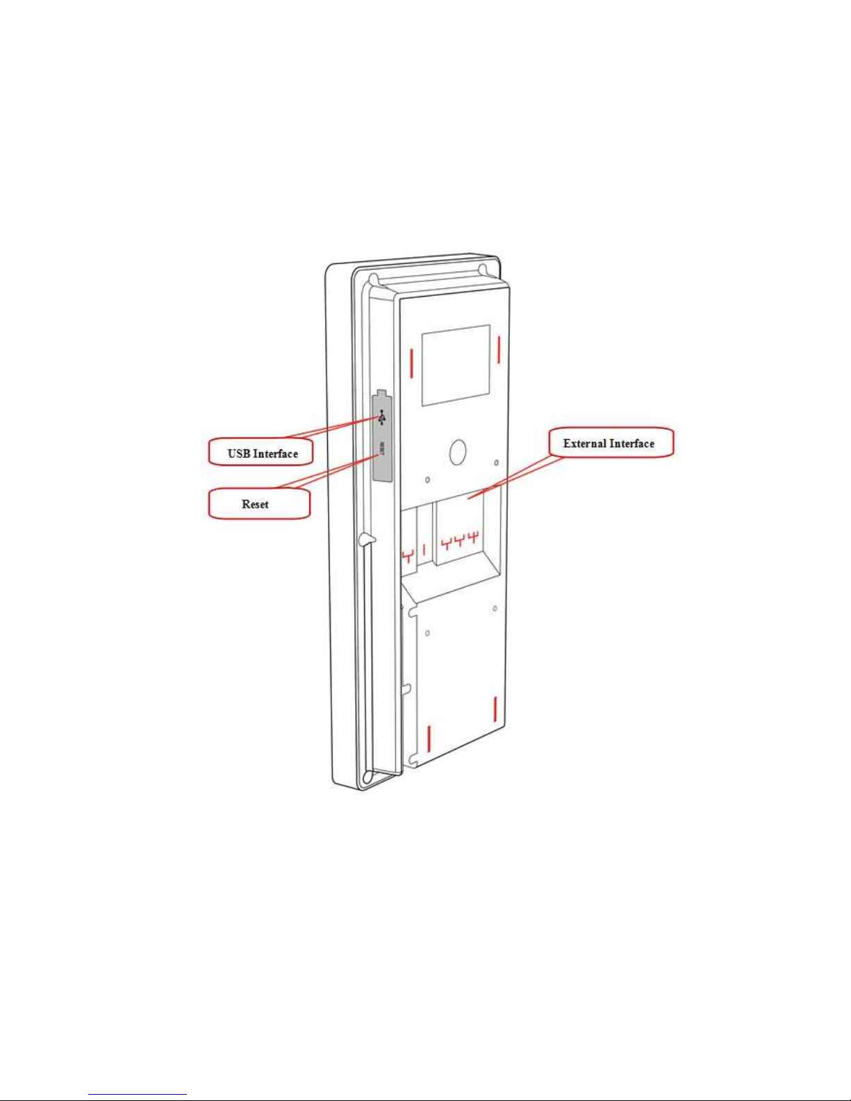
Chapter2 Structure Diagram
PSN 900 Plus PVID structure diagram:
Page 5
4
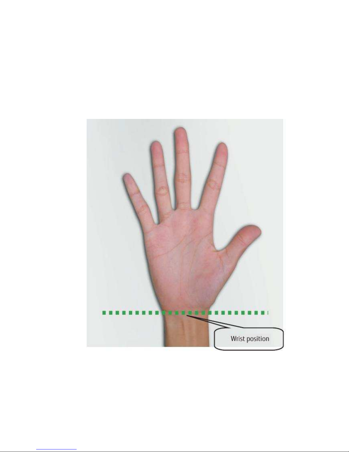
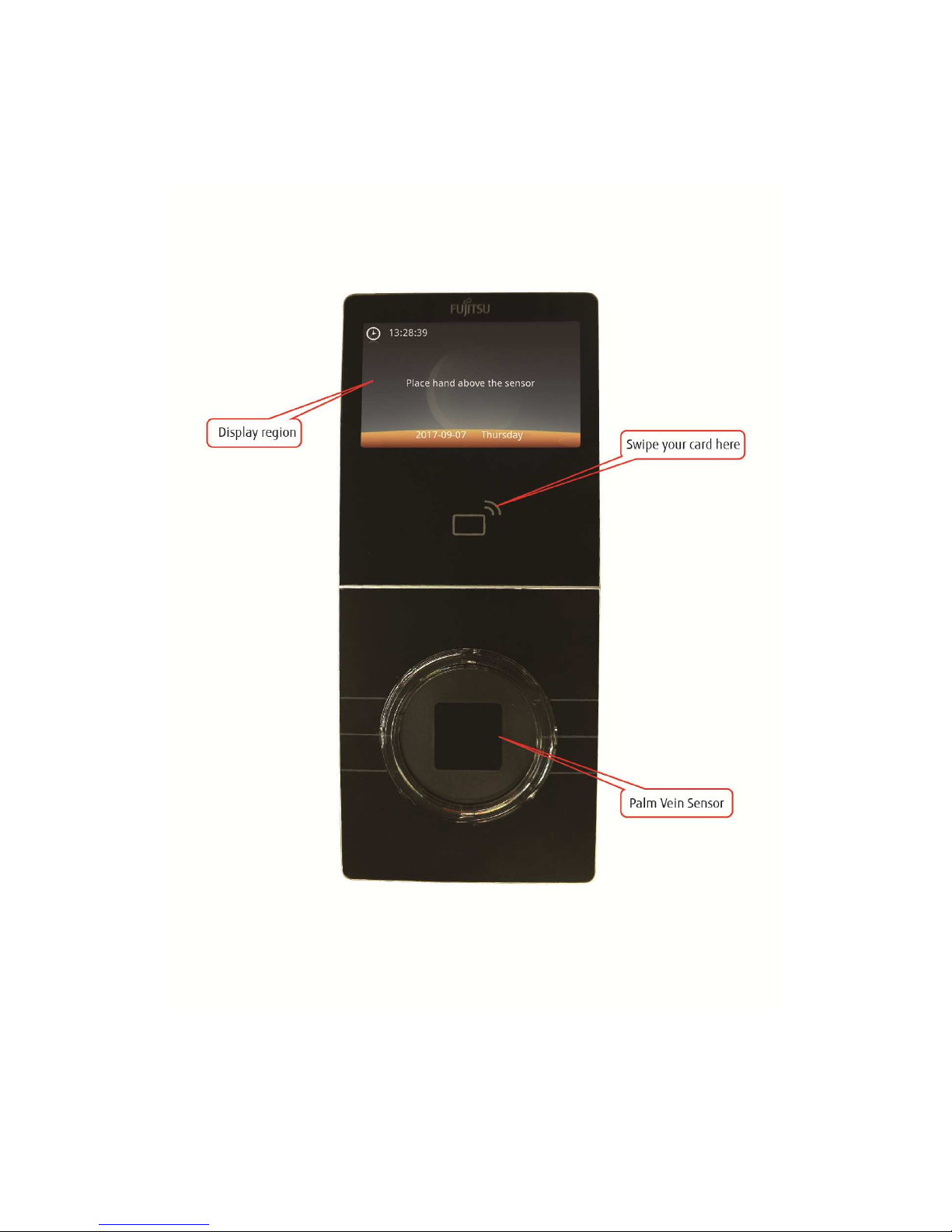
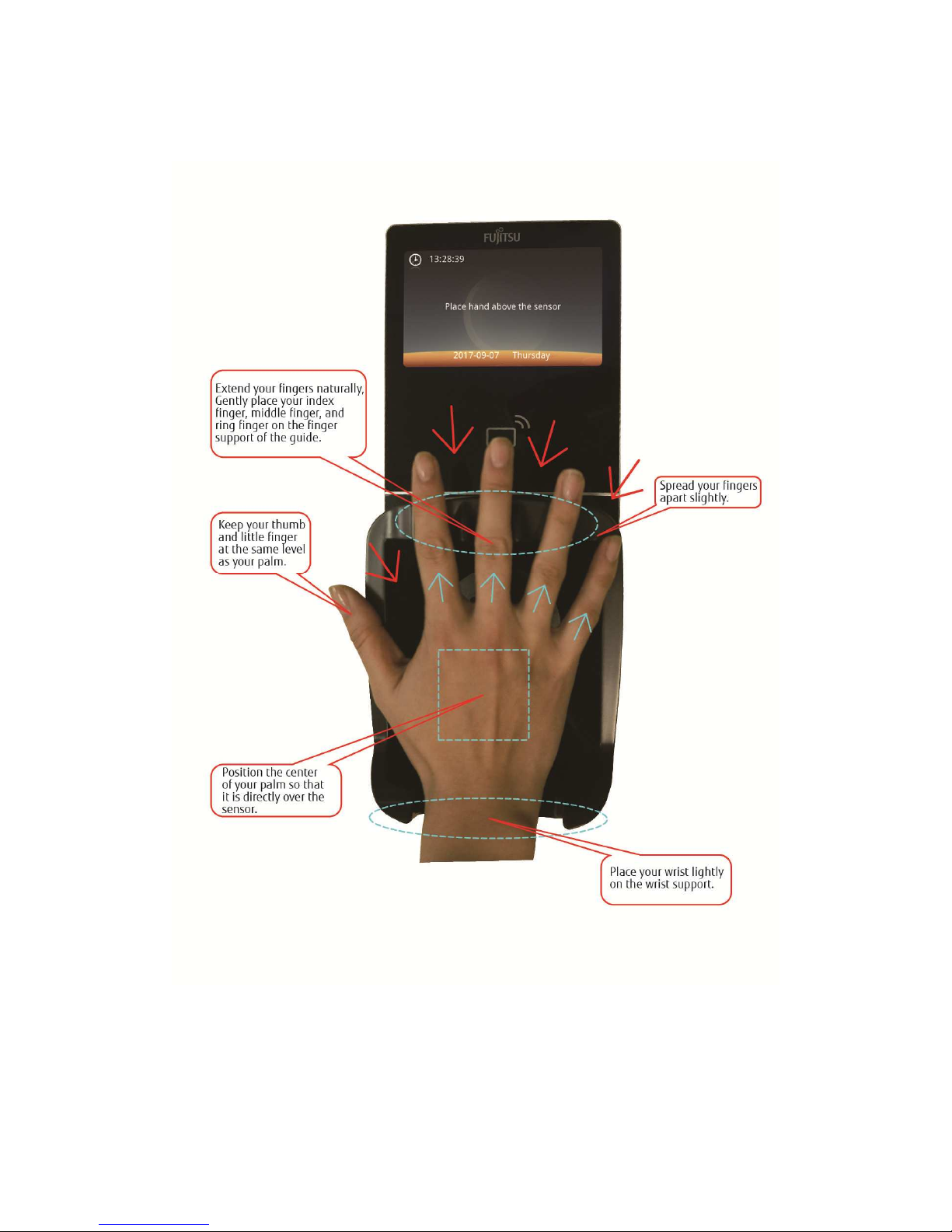
Chapter3 How to Put Hand
Diagram of putting hand:
Page 6
5
Page 7
6
Page 8

7
Note::::
1. Recognition accuracy rate is affected by enrolled palm vein templates.
If the enrolled template is not precise enough (incorrect hand position
or hand bent), even put hands in correct way when verifying, it would
misjudge.
Be sure to use the black palm guide for enrollment.
2. In particular, if it is not prompted to remove the hand, please make
sure not to remove the wrist from the Wrist-support during the
enrollment process.
3. When using the transparent circle to do identification or verification:
Since there is no palm guide, except put hands accordance with the
specification requirements strictly, to keep the distance from the palm
to the sensor should be 40 ~ 60mm; if it prompts to adjust the palm
location repeatedly, this means that you did not mastered skills to put
hands yet, please replace the circle with a palm guide..
4. In the following cases, your enrolled palm vein templates may be
incorrect, authentication errors(false reject) may repeated occur:
1) Hand wrapped with bandage.
2) Hands are unclean, wet or injured.
5. Please keep the sensor surface clean. If dirty, just wipe it gently with
dry and soft clean cloth; don’t clean the sensor surface by water or
organic solvents.
6. Recommend installing the product indoors, cannot be exposed to direct
sunlight.
Page 9
8
Chapter4 Operating Instructions
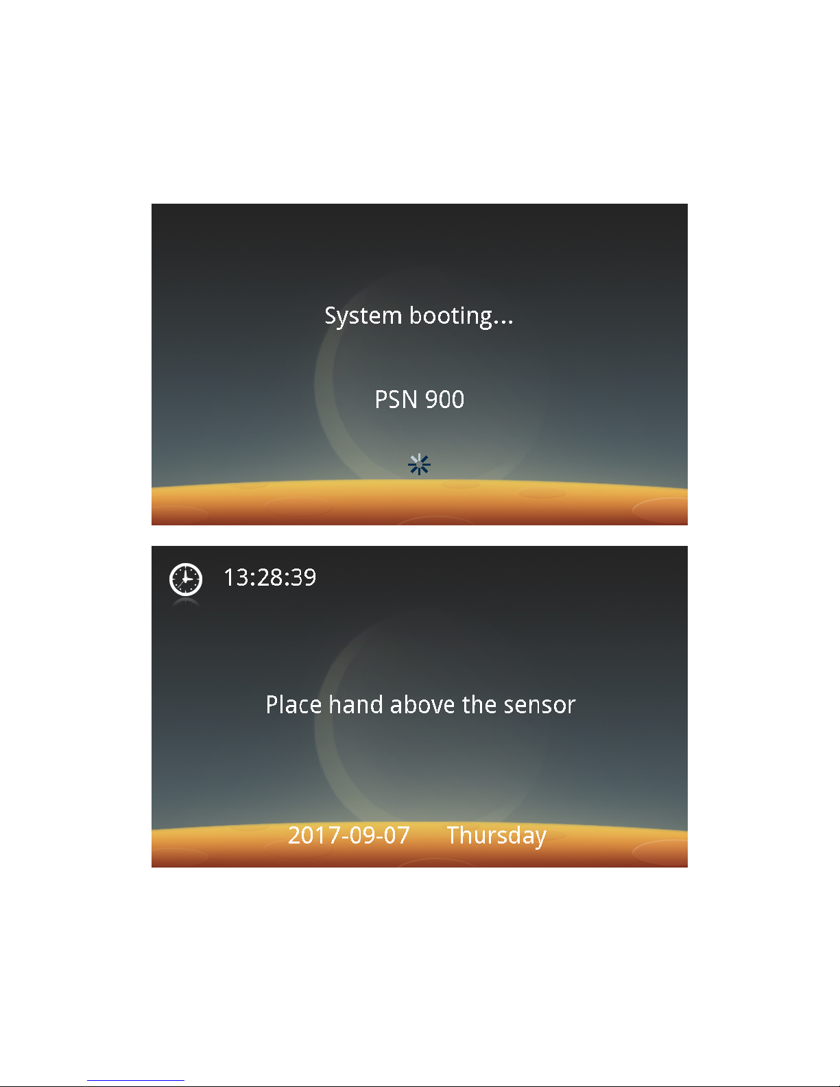
Step 1: Plug in the connection terminals of the power adapter. Turn on the
power supply.The Palm Vein Identification Device boots up and the following
screen appears:
After the boot-up is completed, the idle screen appears.
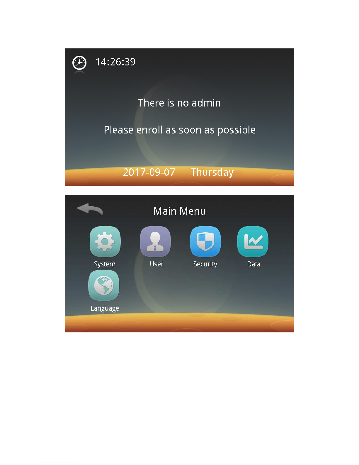
Step 2: Click the touch screen and then the Management button to enter the
following screen. If no system user is registered as an administrator, it will prompt
that an administrator should be registered duly.
Note: A maximum of 10 administrators can be registered.
Page 10
9
Then enter the main menu screen as follows:
Step 3: Click "Manage" to enter the system settings screen. Click "Work mode"
to enter the screen for selecting a work mode – Palm Vein, Card + Palm Vein, PIN
Code + Palm Vein, or Group No. + Palm Vein mode. Select the work mode to be
used, and then you can register an administrator or user.
1. Palm Vein
2. Card + Palm Vein (recommended)
3. PIN Code + Palm Vein
4. Group No. + Palm Vein
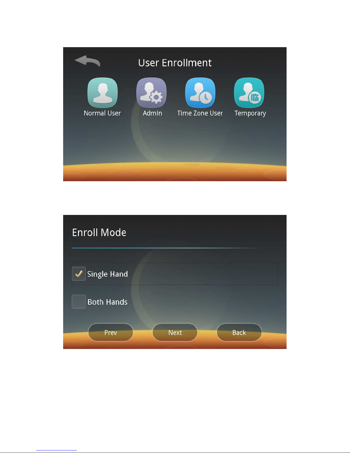
Step 4: After the work mode is selected, click the Back button to enter the
Main Menu screen. Click "User" and "Enroll" in sequence to enter the following user
Page 11
10
registration screen:
Step 5: Select the permissions of the registered user. For example, click
"Admin" to enter the administrator registration process; enter the following
registration mode screen, and then you can select the Single-Hand Registration or
Both-Hands Registration depending on your need.
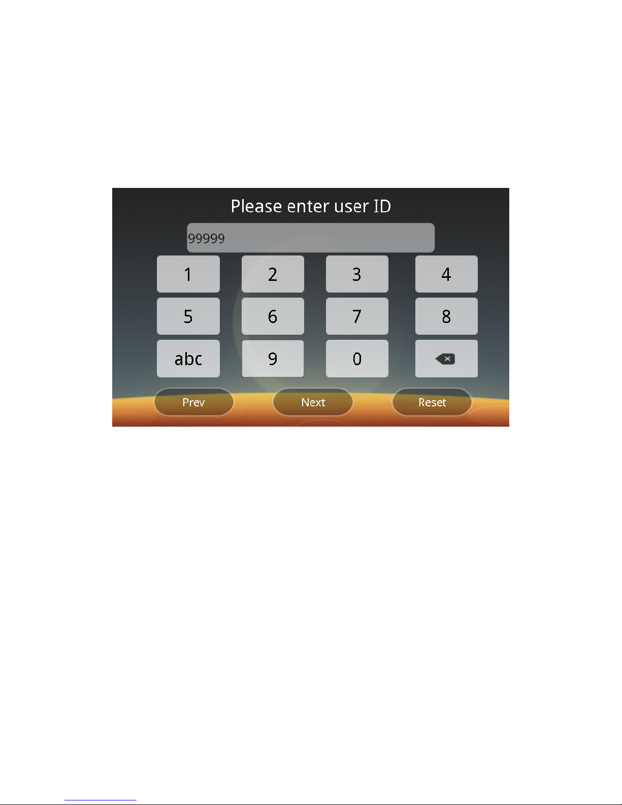
Click the Next button to enter the User ID Settings screen:
1. Input ID settings by touching keys.
ID setting rules: Up to 20 characters, consisting of letters, numbers, or
alphanumeric characters, where letters are not case sensitive.
Note: When assigning a user ID, if there is the same number ID, the user
stored in the management system will cover that stored in the device.
2. If the selected work mode is the PIN Code + Palm Vein mode, the PIN code
Page 12
11
should be set before setting an ID.
PIN code setting rules: Up to 6 characters consisting of numbers, letters or
alphanumeric characters.
3. If the selected work mode is the Group No. + Palm Vein mode, you should
use the PalmPass network management system at the same time to set the
grouping information.
Group setting rules: represented by A/B/C/D + one 1-digit number or one
1-digit number.Users are assigned to different groups.
Click the "Next" button to enter the "Please select the door access control
number type" interface. Set the output door access control number by selecting the
"ID digital part" or "User-defined":
Door access control number setting rules: Up to 10 characters all consisting of
numbers, which can be automatically the numeral part of a user ID or be
customized as required but cannot begin with 0.
Step 6: After the user ID is entered, click the Next button to register a normal
user, administrator, time zone user or temporary user by following screen prompts.
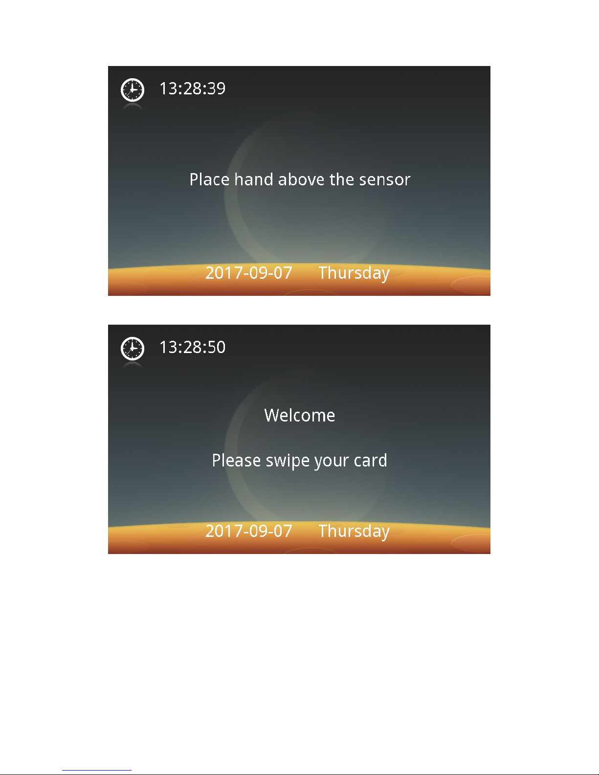
Step 7: Authentication
After different work modes have been registered, different screens for waiting
for Identification or Verification will appear as shown in the figure below. When the
administrator needs to do management, just click on the idle screen, and when the
Management button appears, the administrator can put a hand for authentication.
1. When you are registered in the Palm Vein mode, the idle screen is as
follows:
Page 13
12
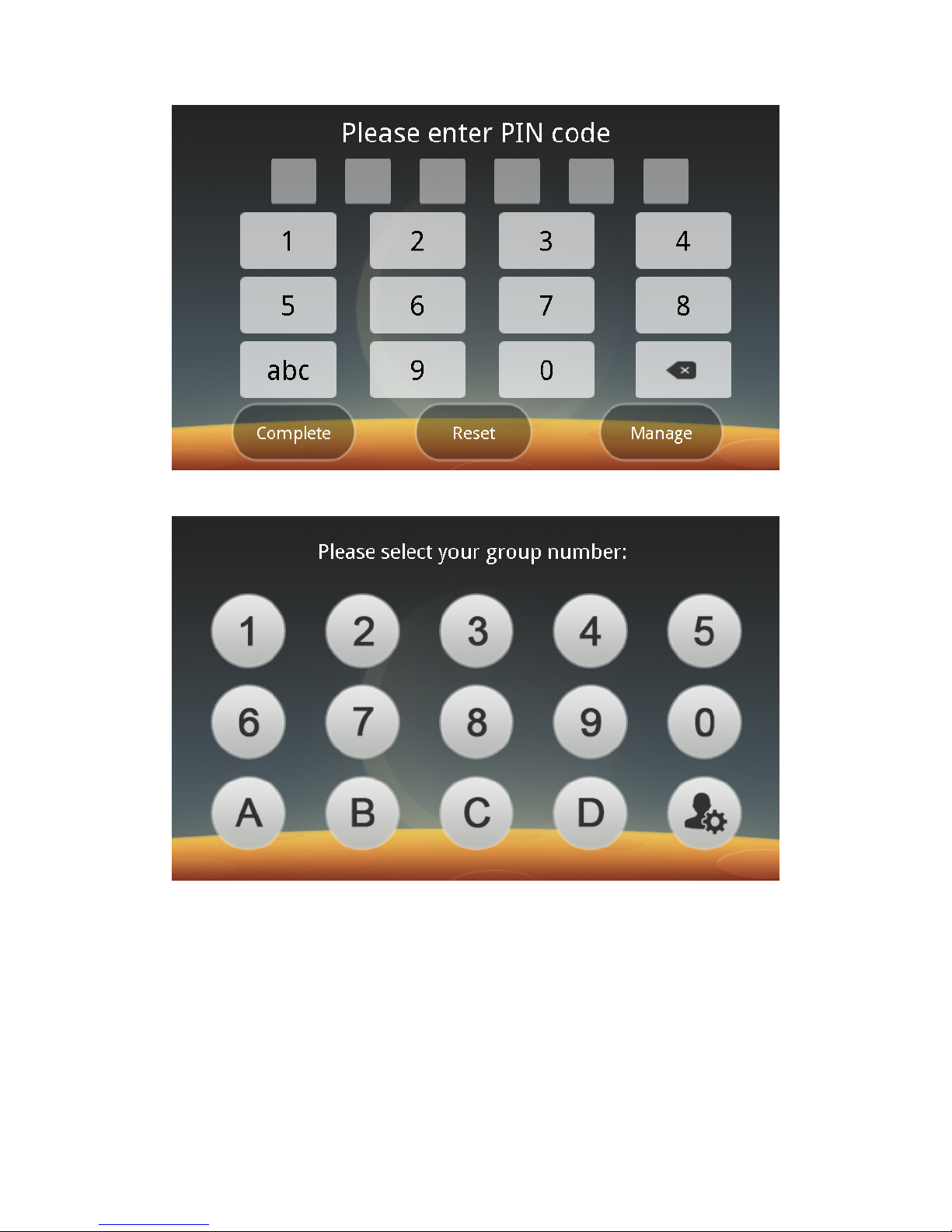
2. When you are registered in the Card + Palm Vein mode, the idle screen is
as follows:
3. When you are registered in the PIN Code + Palm Vein mode, the idle screen
is as follows:
Page 14
13
4. When you are registered in the Group No. + Palm Vein mode, the idle
screen is as follows:
Note: During recognition in different modes, there are acoustic prompts no
matter whether the card swiping or recognition is successful or not.
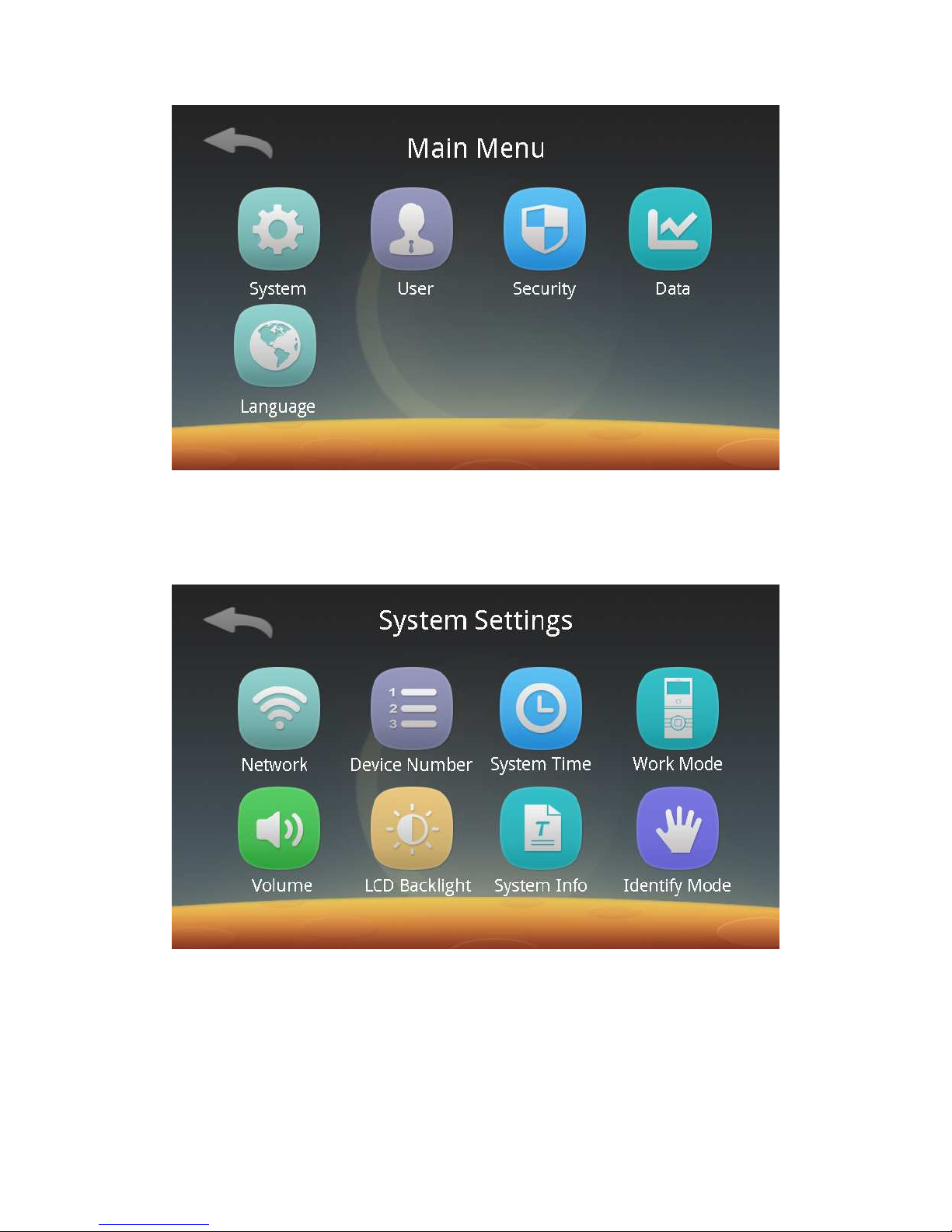
Step 8: Management
Click on the Management button in the idle screen. After the administration is
authenticated, you can enter the Main Menu screen:
Page 15
14
1. System Management:
Click the System Management button to enter the following settings screen.
You can set the network communication, device number, system time, work mode,
system volume and LCD backlight respectively, check system settings, and select a
identify mode.
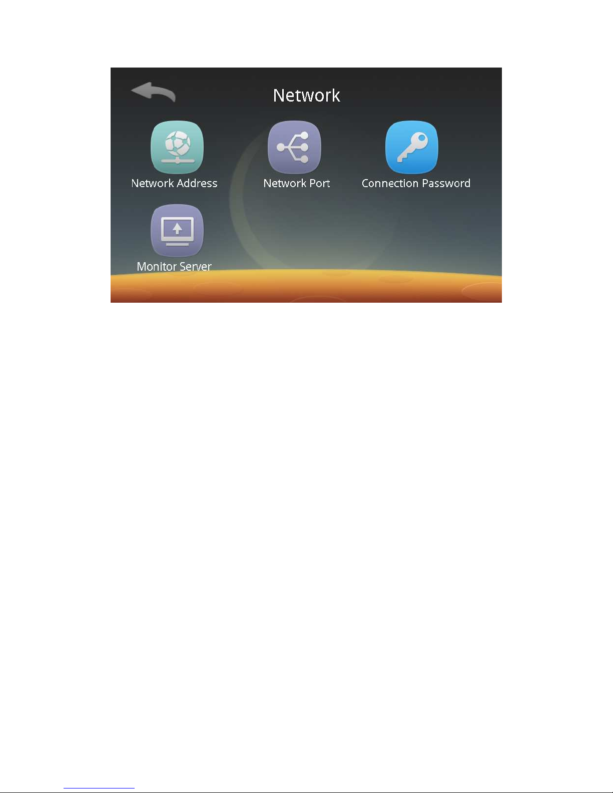
1) Network communication:
Click the Network button to enter the following screen:
Page 16
15
You can follow screen prompts to set the network address, network port
number and connection password respectively. A device can be managed remotely
only when the same access password is set for the PalmPass Network Management
System and the device. The device's default settings:
Network address:
IP Address: 192.168.3.100
Subnet Mask: 255.255.255.0
Gateway: 192.168.3.1
Network Port: 7777
Connection Password: 123456
Monitoring server: Turn on or off the function switch. Enter the server
address.
2) Device Number:
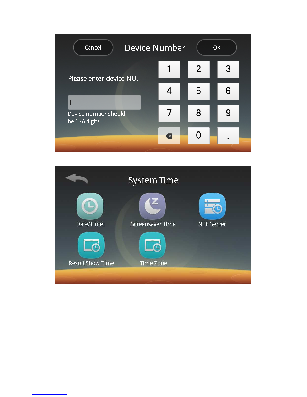
Click the Device Number button to enter the device number setting screen. The
default device number is "1".
Page 17
16
3) System Time:
Click the System Time button to enter the following screen:
You can follow screen prompts to set the date / time, screensaver time, NTP
server, result show time and time zone respectively.
ⅰ. Date / Time: Set the date and time of the device.
ⅱ. Screensaver Time: Set whether the system sleeps. When the system sleeps,
the screen backlight is turned off. The system can wake up when you click on the
screen.
ⅲ. NTP Server: Turn on or off the function switch. Enter the server address. By
default, the time is synchronized with the server time every day.
iv. Result Show Time: Range 0 ~ 10s, set according to needs.
Page 18
17
v. Time Zone: Set the time zone of the terminal, which is GMT + 08:00 (Beijing
time) by default.
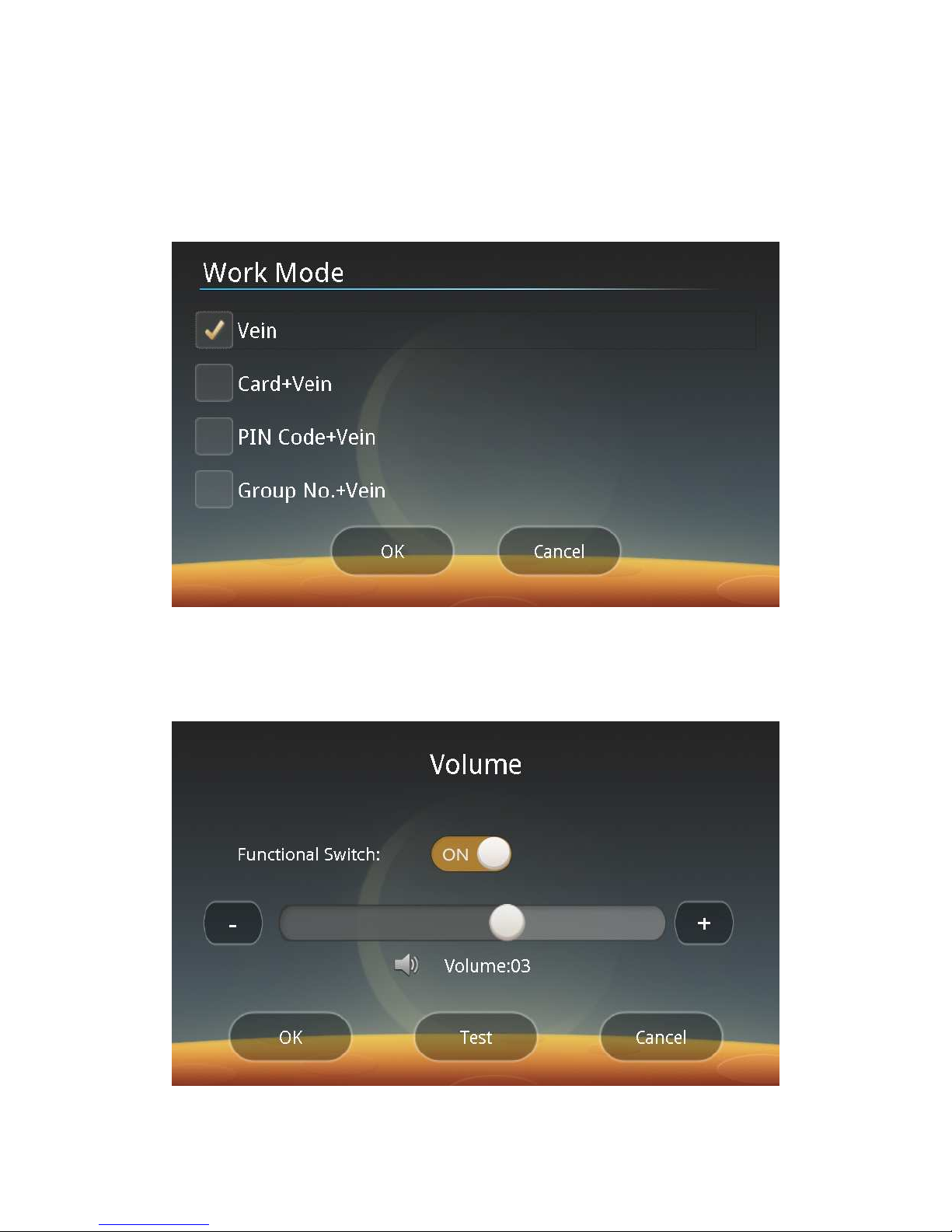
4) Work Mode:
Click the Work Mode button to enter the following screen:
You can follow screen prompts to select the Palm Vein, Card + Palm Vein, PIN
Code + Palm Vein or Group No. + Palm Vein mode depending on your need.
5) System Volume:
Click the Volume button to enter the following screen:
You can follow screen prompts to choose to enable or disable the beep
Page 19
18
depending on your need. If it is enabled, you can click the "+" or "-" button or drag
the slider to increase or decrease the volume. You can carry out audition by clicking
the test button. If the System Beeps is disabled or the beep volume is 0, there will
be no beeps during card swiping, recognition or local alarms.
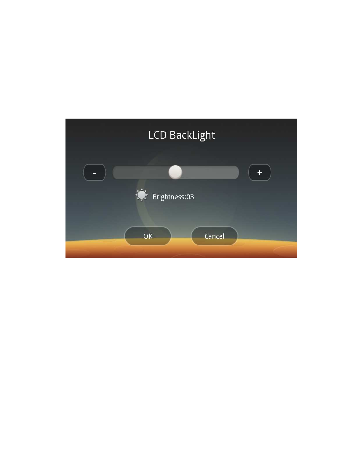
6) Screen Backlight:
Click the LCD Backlight button to enter the following screen:
You can follow screen prompts to click the "+" or "-" button or drag the slider to
increase or decrease the screen brightness, which is recommended to be 03 or less.
The default brightness of the screen backlight is 03.
7) System Information:
You can click the System Info button to check system settings.
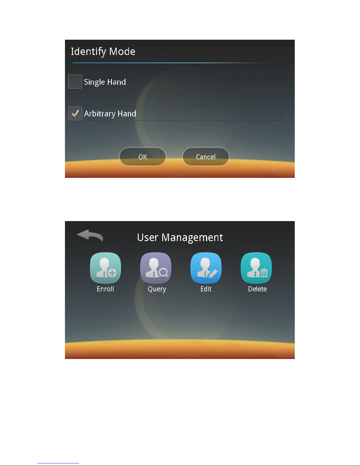
8)Identify Mode
Click the Identify Mode button to enter the following screen. You can select the
Single-Hand Recognition or Arbitrary-Hand Recognition.
Page 20
19
Single-Hand Recognition: During recognition, the hand is compared with the
registered palm first.
Arbitrary -Hand Recognition: Any registered palm can be recognized.
2. User Management:
Click the User Management button to enter the following screen:
You can follow screen prompts to enroll, query, edit and delete users.
1) User Enrollment:
Click “Enroll”. Repeat Step 4, 5 and 6 to register users with different
permissions.
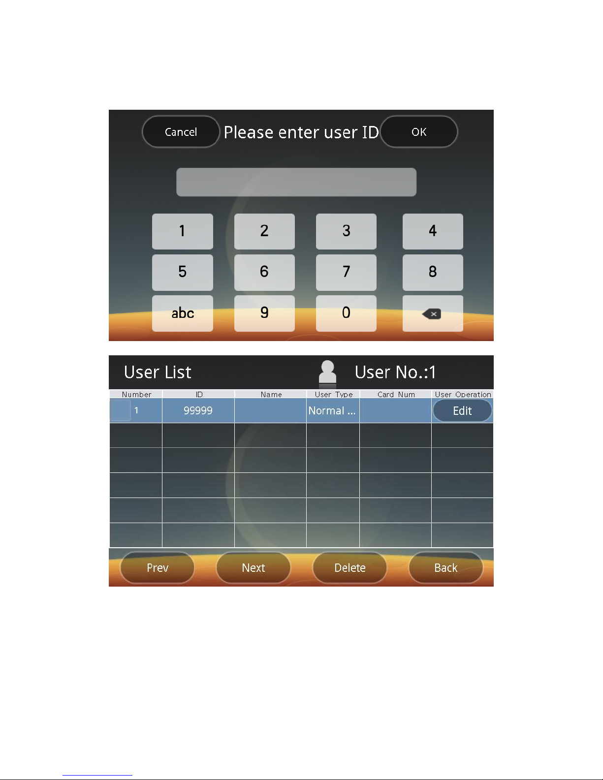
2) Query Users:
You can click “Query” to browse registered users through Precise Search or
Listing.
Page 21
20
ⅰ) Click "Exact Search" to enter the following screen:
Enter a user ID for precise search.
ⅱ) Click "List Mode" to enter the following screen:
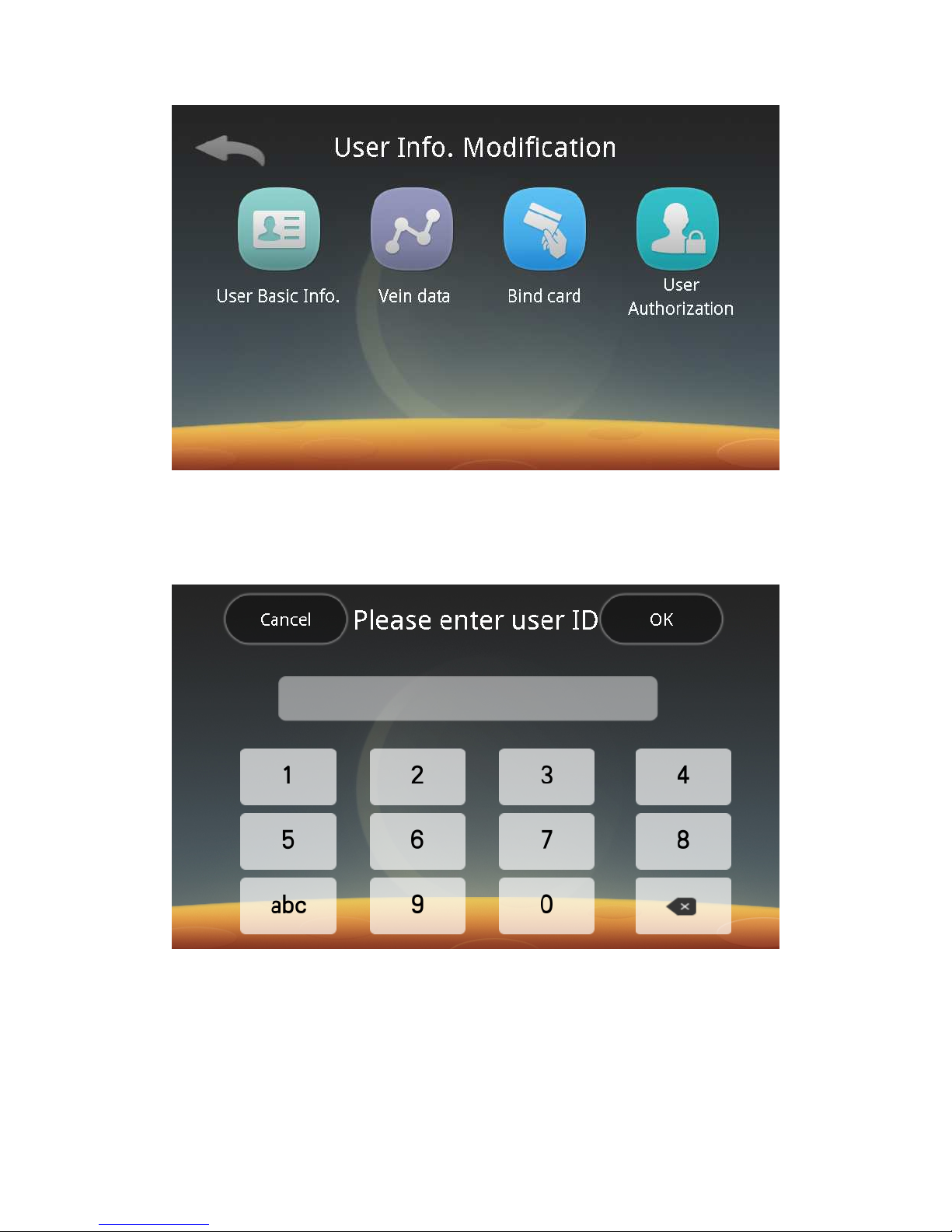
Click the Edit button in the User Operation screen, and then you can enter the
user information editing screen:
Page 22
21
You can follow screen prompts to edit the user’s basic information, vein data
and permissions. When you switch to the Card + Palm Vein mode, you can assign a
card to the user by card swiping.
3) Edit a user:
Click on "Edit" to enter the following interface:
Follow screen prompts to input a user ID and click the Next button to enter the
user information editing screen. You can edit the user’s information with the above
steps.
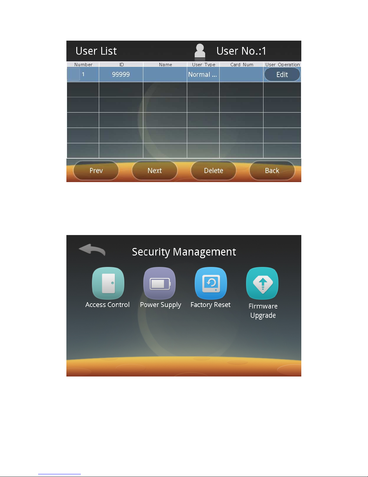
4) Delete Users:
Click the Delete Users button to enter the following screen:
Page 23
22
Follow screen prompts to select users and click the Delete button, and then
the users can be deleted.
3. Security Management:
Click the Security button to enter the following screen, and then you can set
access control options, power supply, restore factory settings and upgrade software
respectively.
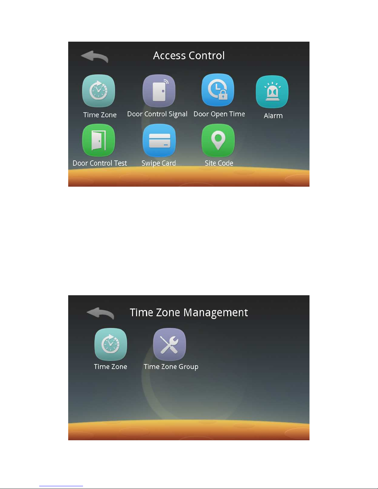
1) Set Access Control:
Click the Access Control button to enter the following screen:
Page 24
23
In this interface, you can carry out time zone management, door access
control signal settings, door open time, alarm settings and door control test, swipe
card reading and Site Code operation.
ⅰ. Time Zone Management:
Click on Time Zone to enter the following interface, and then you can carry out
the oppeartions of Time Zone Information Management and Ttime Zone Group
Management.
Notes:
a.To register a time zone user, you must first set a time zone and a time zone
group. A time zone user has permissions only within the valid time zone.
b.A maximum of 20 time zone and 20 time zone groups can be set.
Page 25
24
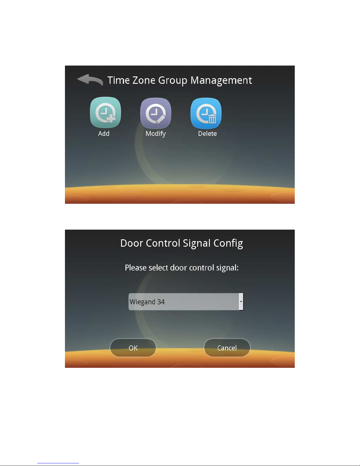
Click on time zone or Time Zone Group Management to enter the following
interfaces respectively, and then you can add, modify and delete time zone and
time zone groups.
ⅱ. Door Control Signal Settings:
Click the Door Control Signal button to enter the following screen:
Follow screen prompts to select an appropriate item:
◆ To be connected to the door controller, select “Wiegand 26” , “Wiegand 34”,
CORP 1K(Corporate 1000) or CSN32;
◆ If an electric lock is connected, select Electric Lock Output.
◆ To be used for work check-in without output, select “No output”.
ⅲ. Door Open Time:
Page 26
25
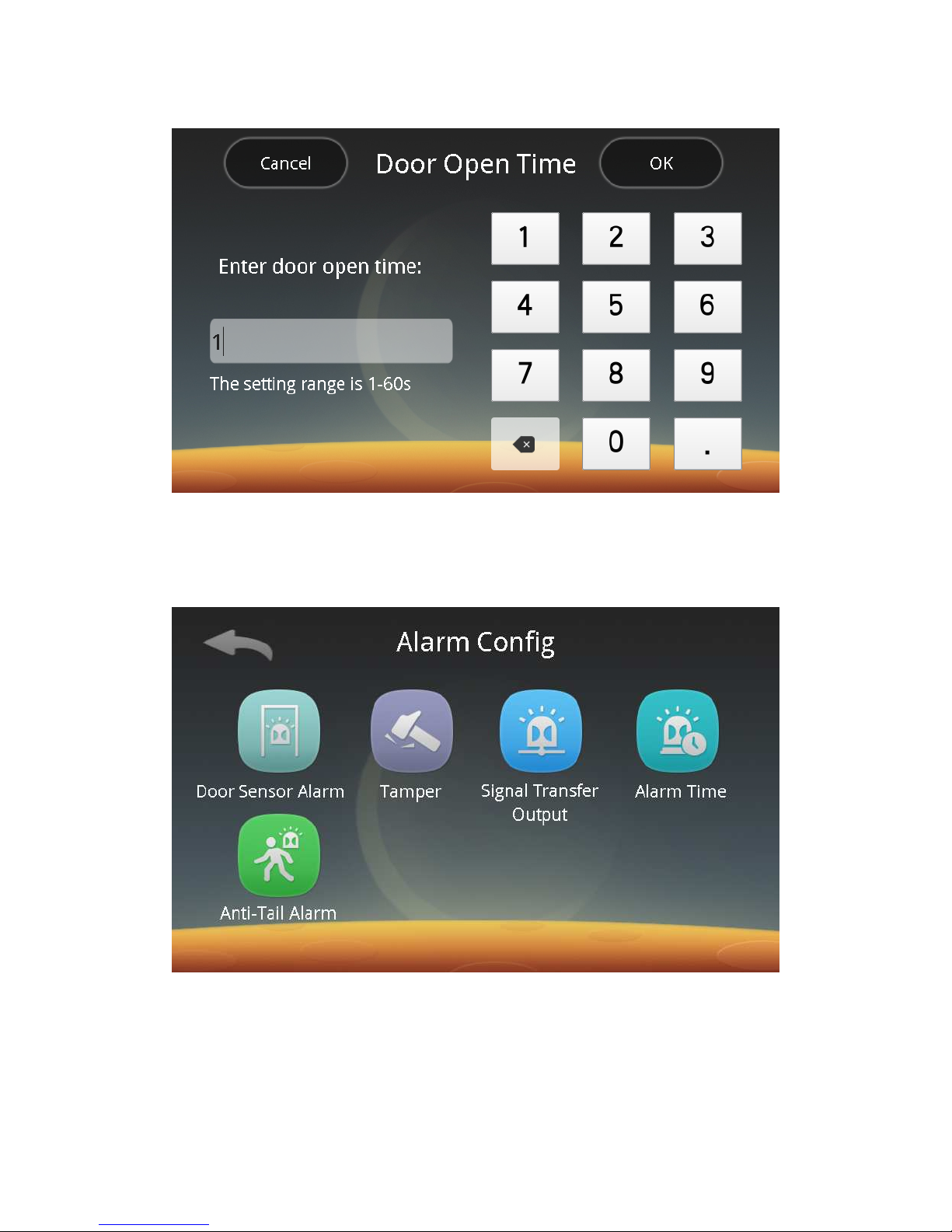
Click the Door Open Time button to enter the following screen:
Follow screen prompts to enter the door open time in a range of 1 ~ 60s.
Note: This function is limited to the case of connecting to the electric lock
directly.
ⅳ. Alarm Settings:
Click the Alarm button to enter the following screen:
You can follow screen prompts to carry out settings of the Door Sensor Alarm,
Tamper Alarm, Alarm Signal Output, Alarm Time, and Anti-Tali Alarm.
ⅰ. Door Sensor Alarm:
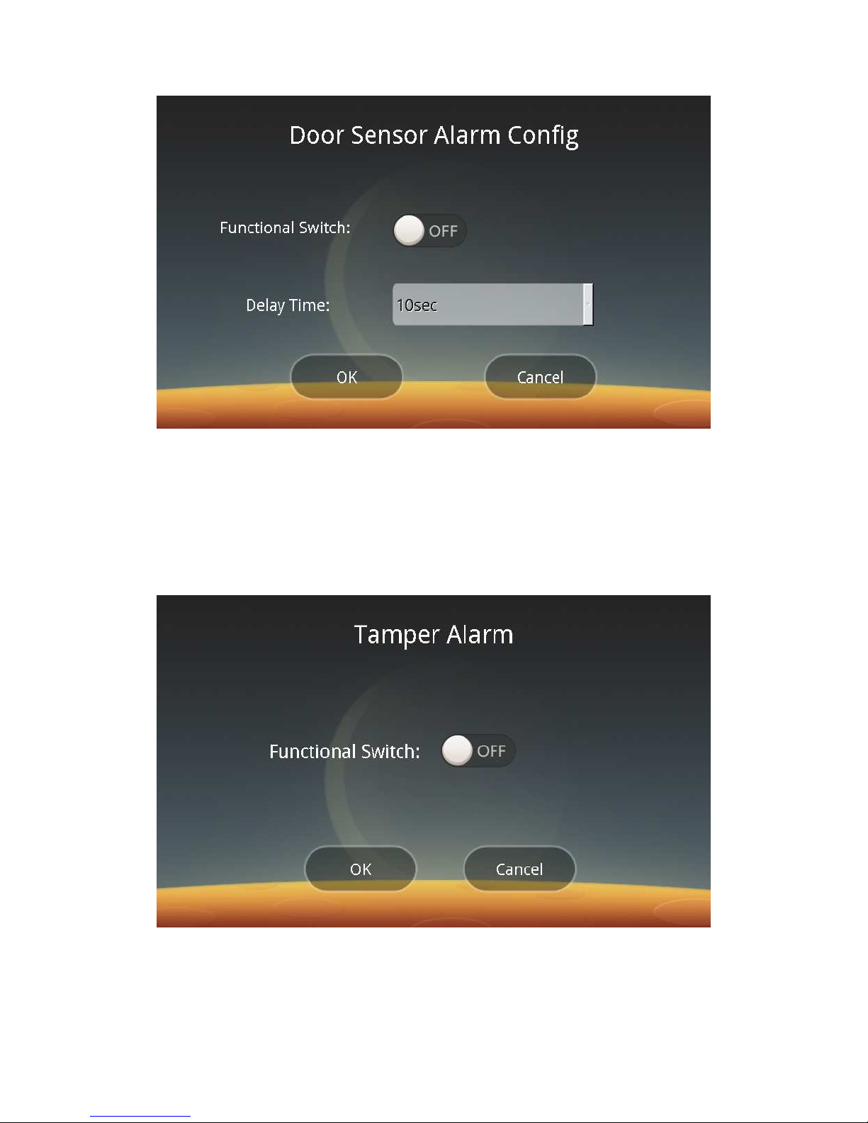
Click the Door Sensor Alarm button to enter the following screen:
Page 27
26
In this screen, you can choose to enable or disable the Door Sensor Alarm
function and set the alarm delay time.
Note: This function is limited to the case of connecting to the electric lock
directly with the door sensor having been connected.
ⅱ. Tamper Alarm:
Click the Tamper button to enter the following screen. You can choose to
enable or disable the Tamper alarm function. If the tamper alarm is enabled, when
the device is dismantled, the device itself or the external alarm will issue an alarm.
ⅲ. Alarm Signal Output:
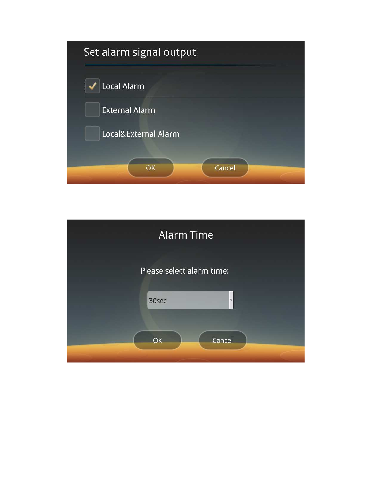
Click the Signal Transfer Output button to enter the following screen, and then
you can select “Local Alarm” or “External Alarm”.
Page 28
27
ⅳ. Alarm Time:
Click the Alarm Time button to enter the following screen, and then you can
choose the alarm duration.
Note: This function is valid only when the alarm is enabled.
ⅴ. Anti-Tail Alarm:
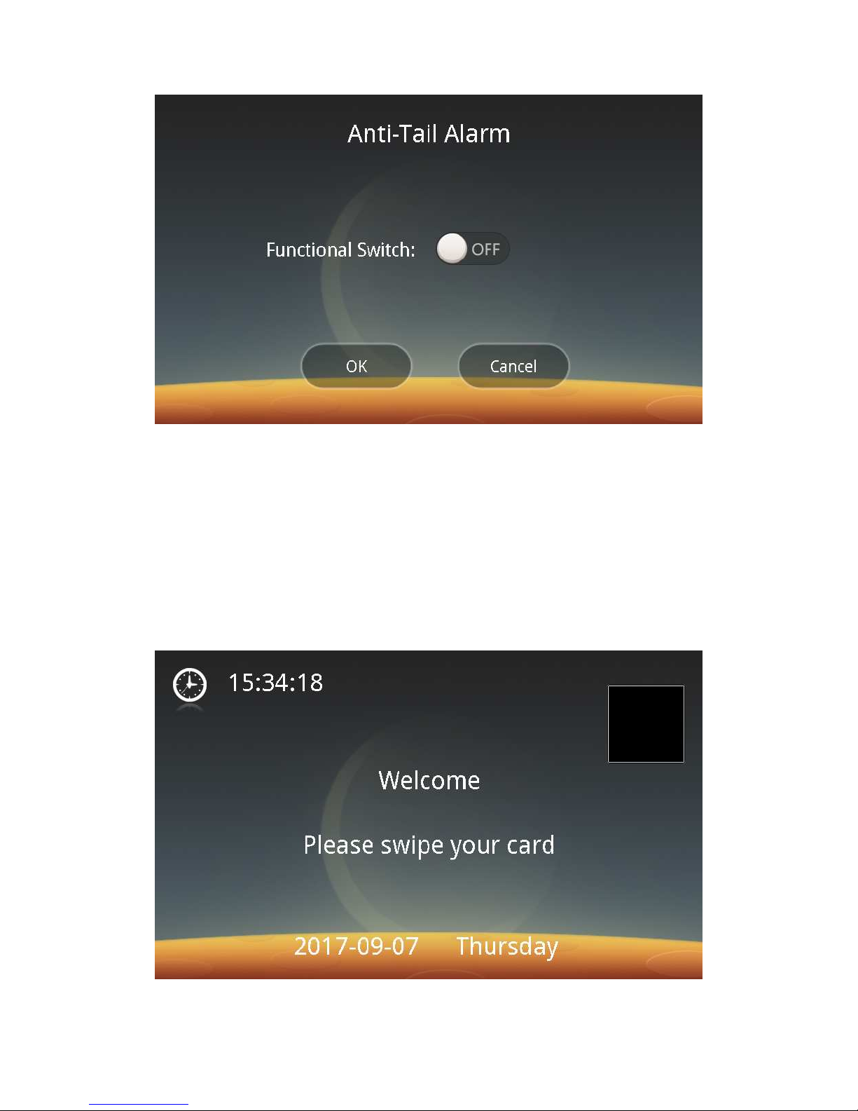
Click the Anti-Tail Alarm button to enter the following screen:
Page 29
28
You can choose to enable or disable the anti-tail alarm function. If it is
enabled, when being dogged or menaced, you can click on the top right area of the
screen (the top right square area, as shown in the figure below), the system will
issue an alarm.
Notes:
a.In order to ensure the safety of the dogged or menaced person, when this
function is enabled, an external alarm must be selected and connected properly.
b.Even if the device is in the sleep state (black screen) or idle state, when
you click the area shown in the figure, an alarm will be issued.
c.The square shown in the figure is used for marking the specified area and
is not visible actually.
ⅵ. The Door Opening Test
Page 30
29
See Chapter5 Output Protocol.
ⅶ. Background card reading:
Click the Swipe Card to enter the background card reading switch. If the
function switch is turned on, the direct swiping mode can also be supported in the
palm vein mode, group No. mode or PIN code + palm vein mode.
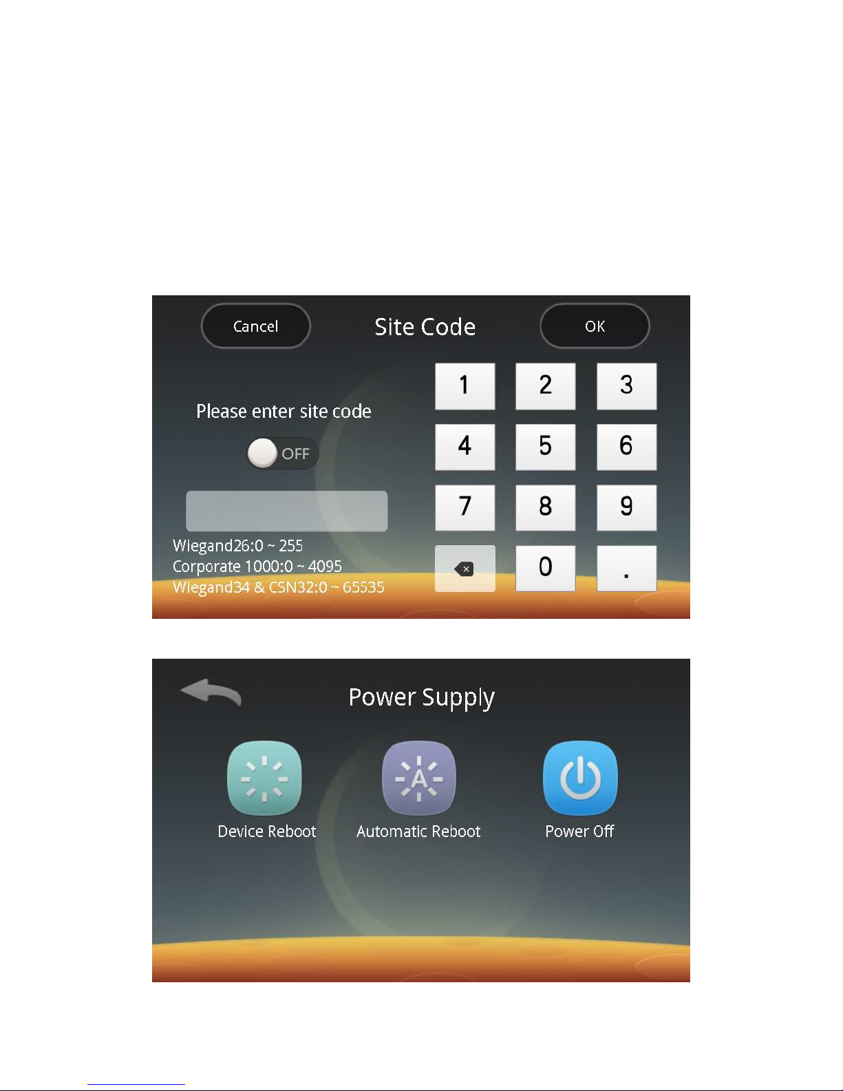
ⅷ. Site Code:
Click the Site Code button to enter the following Site Code setting interface.
Follow the prompts to carry out Site Code settings. See Chapter5 Output Protocol for
details.
2) Power Supply Management:
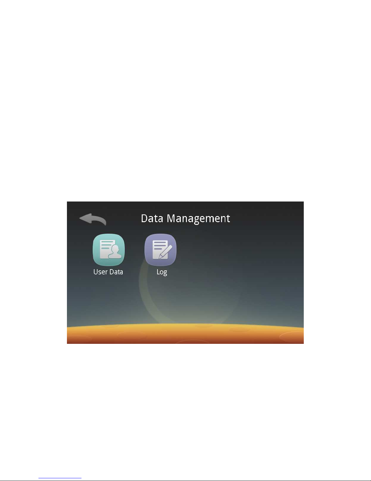
Click the Power Supply button to enter the following screen:
Page 31
30
Click on "Device Reboot" to reboot the device. Click "Automatic Reboot" to
complete the corresponding settings. The device will reboot at the set time. Click
"Power Off", and then the device will be turned off.
3) Restore Factory Settings:
Click the Factory Reset, and then the factory settings of the device will be
restored.
Note: This operation will erase all data and restore to the factory state, please
do it cautiously.
4) Upgrade Firmware:
Insert the U disk stored with the upgrade package into the device and click
"Upgrade Firmware", and then the software can be upgraded.
Upgrade package file format: up010000.tar.gz, where 010000 represents the
version number 01.00.00.
Note: You can upgrade Firmware either with the U disk or remotely through
the PalmPass Network Management System.
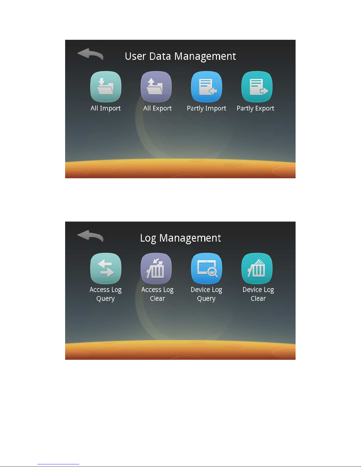
4. Data Management:
Click the Data button to enter the following screen, and then you can manage
user data and records respectively.
1) User Data Management:
Click the User Data button to enter the following interface:
Page 32
31
Follow screen prompts to insert a U disk, and then you can export all or part of
users of the device to the U disk or import all or part of users from a U disk.
2) Records Management:
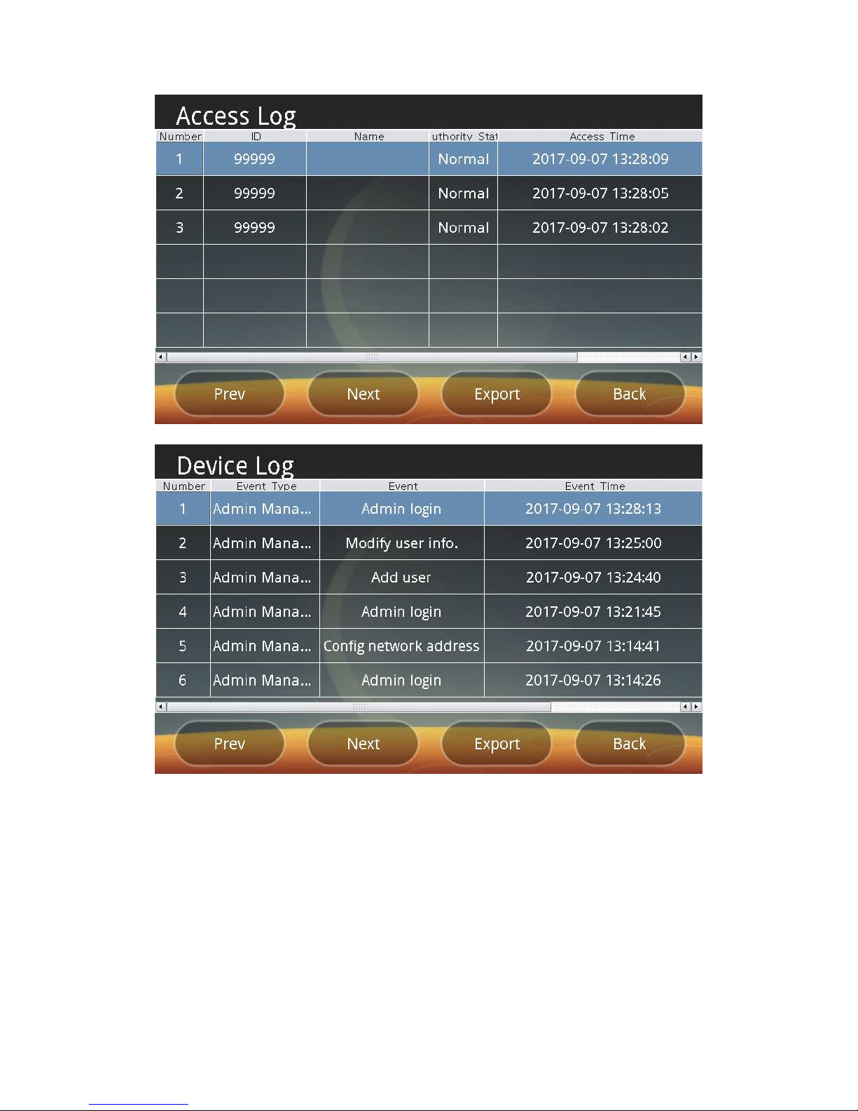
Click the Log button to enter the following screen, and then you can browse
and clear access records as well as the device’s records.
ⅰ. Browse access records and the device’s records:
Click “Access Log Query” and “Device Log Query” respectively to enter the
following screen, and then you can browse access records and the device’s records
respectively or export access records and the device’s records respectively to a U
disk.
Page 33
32
ⅱ. Clear access records and the device’s records:
Click “Access Log Clear” and “Device Log Clear” respectively to enter the
following screen, and then you can clear all of the access records and the device’s
records respectively. Please do this operation cautiously.
Page 34

33
Chapter5 Output Protocol
1. Wiegand port
The device is compatible with the Wiegand 26/34 output format. The contents
of the protocol are as follows:
1) “Site Code” is disabled
The Card + Palm Vein mode (1: 1 verification)
i. IC card: If the hexadecimal card number of an M1 S50 registration card is
74C3CAFB, then:
a) When it is outputted in the Wiegand 26 output format, the last 3 bytes of
the card number will be output, i.e., C3CAFB
b) When it is outputted in the Wiegand 34 output format, the last 4 bytes of
the card number will be output, i.e., 74C3CAFB
ii. For an ID card, the first 10 digits of the card number shown on the back of
the card will be read. The Wiegand output format is the same as that of the IC card.
The Palm Vein mode (1: N Identification)
In this mode, the door access control number is the output number. See
step5 in "Operation instructions" for the door access control number setting
rules.
The Pin Code + Palm Vein mode (1: 1 Verification)
The output method of this mode is the same as that of the Palm Vein
mode.
2) “Site Code” is enabled
If the hexadecimal card number of a registration card is 74C3CAFB and the
Site Code is set to be 200 (decimal), then:
a) If the output format is Wiegand 26, the last two bytes of the output Site
Code and card number is C8CAFB.
b) If the output format is Wiegand 34, the last two bytes of the output Site
Code and card number is 00C8CAFB.
c) If Corporate 1k is selected, the Site Code and card number will be output.
d) If CSN 32 is selected, the last two bytes of the Site Code and the card
number will be output without a parity bit: 00C8CAFB
2. Electric lock and exit switch ports
The device can be connected directly to the electric lock and exit switch. See
Wiring Instructions for the connection method.
3. Alarm / Doorbell ports
The device can be connected to an external alarm or doorbell. See Wiring
Instructions for the connection method.
4. The Door Opening Test function
If the device is connected to the door controller, the number sent for the
door-opening test is "1000000". A valid number "1000000" need to be registered on
the door controller before the door-opening test is carried out. If the device is
connected to the electric lock, the door can be opened directly.
Page 35

34
Chapter6 Trobuleshooting
Faults and causes:
1. If the screen prompts "Sensor initialization failed", please contact the supplier
to handle it.
2. Errors occur repeatedly during recognition: The registered palm vein sample is
probably inaccurate. Please re-register it. In addition, be sure to use the black
bracket to register a palm vein sample.
3. When the transparent aperture is used during recognition or authentication, if
you are prompted repeatedly to adjust the position of your palm: It shows that
you do not master the hand placement skill well enough, and you are
suggested to use a palm guide support instead.
4. Registration failure: Please check whether the ambient lighting meets the
requirements, the sensor surface is dirty, the palm is clean and the palm is
placed correctly.
5. The device is connected to the door controller where the recognition is
successful but the door cannot be opened: Please check whether you have
been registered as a valid user for the door controller and have the permission
to open the door. The administrator should enter the Set Access Options of the
Security Management to carry out the Door Opening Test before determining
whether it is due to a door controller or device fault.
6. Card swiping error: Please check whether the card swiping position is correct,
whether the card is an M1 S50 card or ID card and whether it has been
registered.
 Loading...