

Page 1

AN706-00044-1v0-E
32-BIT MICROCONTROLLER
MB9B100A/MB9B300A/MB9B400A/MB9B500A Series
FM3 family inverter solution
GUI User Manual
TM
ARM and Cortex-M3 are the trademarks of ARM Limited in the EU and other countries.
Page 2

AN706-00044-1v0-E
All Rights Reserved.
The contents of this document are subject to change without notice. Customers are advised to consult with
FUJITSU sales representatives before ordering.
The information, such as descriptions of function and application circuit examples, in this document are
presented solely for the purpose of reference to show examples of operations and uses of Fujitsu
semiconductor device; Fujitsu does not warrant proper operation of the device with respect to use based on
such information. When you develop equipment incorporating the device based on such information, you
must assume any responsibility arising out of such use of the information. Fujitsu assumes no liability for
any damages whatsoever arising out of the use of the information.
Any information in this document, including descriptions of function and schematic diagrams, shall not be
construed as license of the use or exercise of any intellectual property right, such as patent right or
copyright, or any other right of Fujitsu or any third party or does Fujitsu warrant non-infringement of any
third-party’s intellectual property right or other right by using such information. Fujitsu assumes no liability
for any infringement of the intellectual property rights or other rights of third parties which would result from
the use of information contained herein.
The products described in this document are designed, developed and manufactured as contemplated for
general use, including without limitation, ordinary industrial use, general office use, personal use, and
household use, but are not designed, developed and manufactured as contemplated (1) for use
accompanying fatal risks or dangers that, unless extremely high safety is secured, could have a serious
effect to the public, and could lead directly to death, personal injury, severe physical damage or other loss
(i.e., nuclear reaction control in nuclear facility, aircraft flight control, air traffic control, mass transport
control, medical life support system, missile launch control in weapon system), or (2) for use requiring
extremely high reliability (i.e., submersible repeater and artificial satellite).
Please note that Fujitsu will not be liable against you and/or any third party for any claims or damages
arising in connection with above-mentioned uses of the products.
Any semiconductor devices have an inherent chance of failure. You must protect against injury, damage or
loss from such failures by incorporating safety design measures into your facility and equipment such as
redundancy, fire protection, and prevention of over-current levels and other abnormal operating conditions.
If any products described in this document represent goods or technologies subject to certain restrictions on
export under the Foreign Exchange and Foreign Trade Law of Japan, the prior authorization by Japanese
government will be required for export of those products from Japan.
The company names and brand names herein are the trademarks or registered trademarks of their
respective owners.
Copyright© 2011 FUJITSU SEMICONDUCTOR LIMITED all rights reserved
1
Page 3

Revision History
Rev Date Remark
1.0 Jul. 14, 2011 First Edition
AN706-00044-1v0-E
2
Page 4

AN706-00044-1v0-E
Table of Contents
Revision History.................................................................................................................... 2
Table of Contents.................................................................................................................. 3
1 Introduction.................................................................................................................... 4
2 System requirements.....................................................................................................5
2.1 Supported Operating Systems: ..............................................................................5
2.2 Supported software environment............................................................................5
3 Install GUI...................................................................................................................... 6
4 Simply install steps about the communication Driver..................................................... 7
4.1 To install FTDI driver in Windows XP......................................................................7
4.2 To install FTDI driver in Windows 7 ........................................................................ 7
5 How to use the GUI .......................................................................................................8
5.1 Overview ................................................................................................................8
5.2 PC Connection with the hardware .......................................................................... 8
5.3 GUI Startup.............................................................................................................9
5.4 GUI software windows’ name and function........................................................... 10
5.4.1 Inverter Platform software introduce.............................................................. 10
5.4.2 Main window ................................................................................................. 11
5.4.3 Function/parameter settings window ............................................................. 13
5.4.4 Signal selection window ................................................................................ 17
5.4.5 Graphic window............................................................................................. 19
5.4.6 Variable window ............................................................................................23
5.4.7 Constant window ........................................................................................... 24
5.5 Example of total operating Procedure ..................................................................25
5.5.1 Hardware preparation.................................................................................... 25
5.5.2 GUI software operating step.......................................................................... 25
6 Appendix...................................................................................................................... 34
6.1 Particular Install steps about the communication Driver .......................................34
6.1.1 To install FTDI device in Windows XP........................................................... 34
6.1.2 FTDI Drivers Installation guide for Windows 7............................................... 42
6.2 Motor parameter item ........................................................................................... 55
3
Page 5

AN706-00044-1v0-E
1 Introduction
This user manual describes how to use FUJITSU’S FM3 Inverter Platform GUI.
In Chapter 2, it explains system requirements for the GUI software.
In Chapter 3, it explains how to install the GUI software.
In Chapter 4, it explains how to install the communication driver (FTDI).
In Chapter 5, it explains how to use the GUI.
4
Page 6

AN706-00044-1v0-E
2 System requirements
The GUI software supported environment on PC
2.1 Supported Operating Systems:
Windows Server 2003, Windows Server 2008, Windows Vista, Windows XP, Windows 7
1. Microsoft Windows XP Service Pack 2 or Service Pack 3
Minimum of 192 MB of RAM (384 MB preferred)
At least a 1 GHz processor (1.6 GHz preferred)
2. Microsoft Windows Vista or Windows Vista SP1
Minimum of 768 MB of RAM (1 GB preferred)
At least a 1.6 GHz processor (2.2 GHz preferred)
3. Microsoft Windows Server 2003 Service Pack 2 or Windows Server 2008
Minimum of 768 MB of RAM (1 GB preferred)
At least a 1.6 GHz processor (2.2 GHz preferred)
2.2 Supported software environment.
Microsof
Note: This software is necessary.
t.NET Framework 2.0(over this version preferred)
5
Page 7

AN706-00044-1v0-E
3 Install GUI
Install the GUI software in your PC
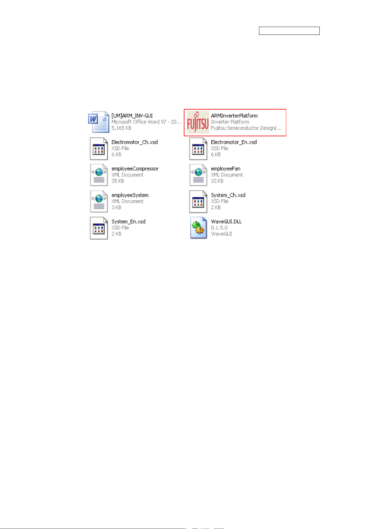
This FUJITSU’S FM3 Inverter Platform GUI is given by compressed file, please copy and
unzip the “FUJITSU’S FM3 Inverter platform GUI.zip” file to your PC. Then, you will find 10
files in the “FUJITSU’S FM3 Inverter platform GUI” folder.
Table 3-1: GUI files
File name Remarks
1 ARMInverterPlatform.exe the Software Executable file
2 Electromotor_Ch.xsd
3 Electromotor_En.xsd
4 System_Ch.xsd
5 System_En.xsd
6 employeeCompressor.xml
7 employeeFan.xml
8 employeeSystem.xml
9 WaveGUI.DLL wave widget dynamic link libraries
10 [UM]ARM_INV-GUI.doc User manual
Parameter type file
the palm parameter database
(Configuration file)
6
Page 8

AN706-00044-1v0-E
4 Simply install steps about the communication Driver
A simply install steps for the FTDI.
4.1 To install FTDI driver in Windows XP
Simply install steps:
1. Connect the FTDI device (board) to a USB port on the PC.
2. New Hardware Wizard will launch.
3. Select "Install from a list or specific location (Advanced)".
4. Select "Search for the best driver in these locations" and enter the file path in the
combo-box.
5. Install the “ftd2xxx.dll”file in the PC.
6. The same way to install the “ftserui2.dll” file in the PC.
The particular install steps, please refer Chapter 6.1.1
To install FTDI driver in Windows 7
4.2
1. Connect the FTDI device (board) to a USB port on the PC.
2. Open Control Panel, select Hardware and Setting, Device Manager, and Other
Devices, then click right button on the mouse, select Update Driver Software, select
the second option to browse manually, select address of drivers have been saved
and finally install the “ftd2xxx.dll ”in the PC.
3. The same way to install the “ftserui2.dll” file in the PC.
The particular install steps, please refer Chapter 6.1.2
7
Page 9
AN706-00044-1v0-E
5 How to use the GUI
Introduce the GUI software
5.1 Overview
This GUI use to cooperate with the FUJITSU’S FM3 inverter platform, customer can use this
GUI to:
1. Real-time control the motor and PFC module function;
2. Real-time setting the motor functions and parameters;
3. Real-time observation of motor running state, used variables and current waveform
shape.
4. Real-time observation of system information, and so on.
It’s means that the GUI is ordered to help customer debug the inverter platform and motor
rotation.
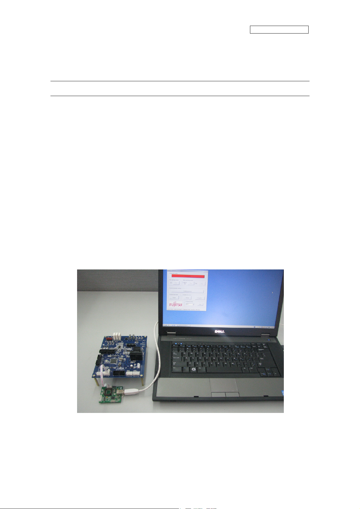
5.2 PC Connection with the hardware
The ha
USB port. Please refer Figure 5-1: Connect
rdware need to use Serial Port connected FTDI, and FTDI connects with PC use
Figure 5-1: Connection
8
Page 10
AN706-00044-1v0-E
5.3 GUI Startup
Open the folder; double click the “ARMInverterPlatform.exe” to run the software, as Figure
5.2.
Figure 5-2: GUI files
9
Page 11
5.4 GUI software windows’ name and function
AN706-00044-1v0-E
5.4.1
Inverter Platform software introduce.
- Name: Platform
- Function: language setting, contain all function windows, and so on.
Figure 5-3: Inverter Platform
10
Page 12
AN706-00044-1v0-E
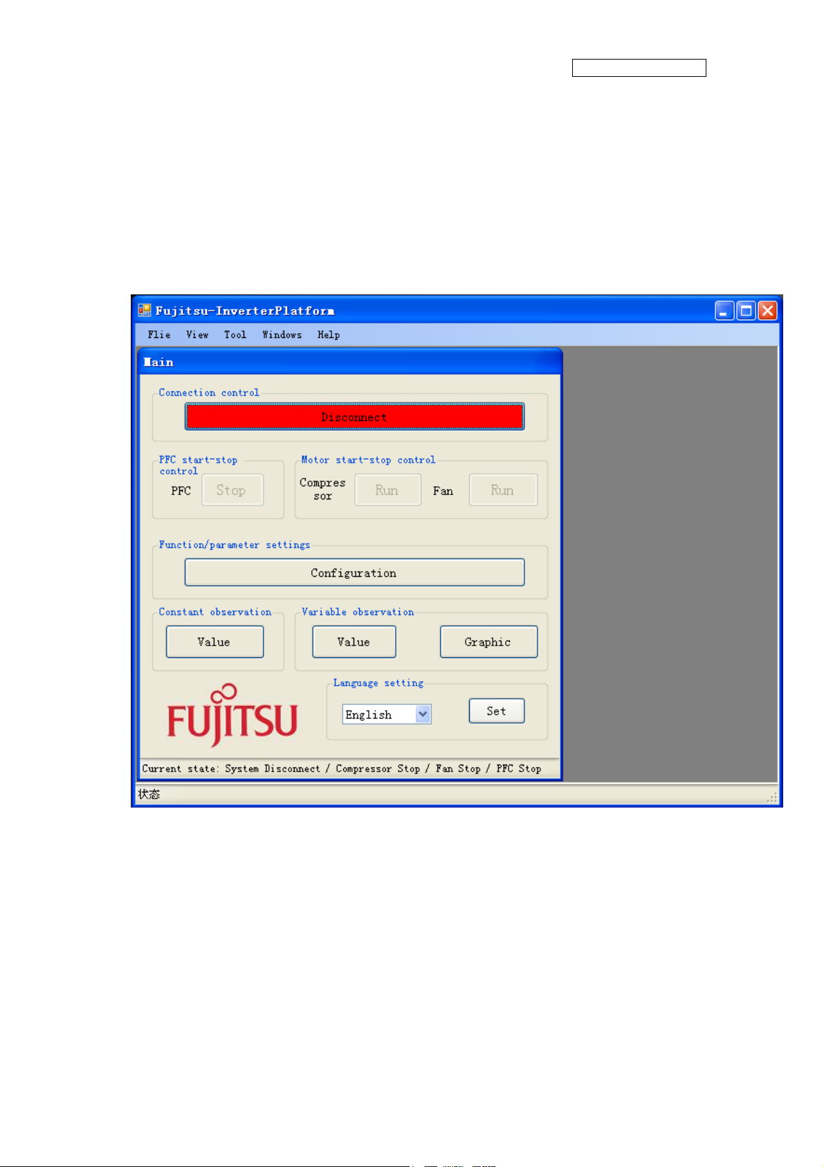
5.4.2 Main window
- Name : Main window
- Function: connect control, start/stop control, function/parameter setting,
Constant/variable observation, language setting, and current state.
1
6
Figure 5-4: main window
Table 5-1: main window function
Name of button Specification
1 Connect
3
5
Init the FTDI and Connect with MCU
4
8
9
10
2 PFC start-stop control
3 Compressor start-stop control
4 Fan start-stop control
5 Function/Parameter setting
11
Operate PFC module function start / stop
Operate compressor start/stop
Operate fan start / stop
Set motor function and parameter.
If the button is pushed, the configuration window opens.
(See Chapter 4.4.2)
Page 13

6 Constant observation
7 Variable observation
8 Graphic
9 Language setting
AN706-00044-1v0-E
Observe system state, motor state, motor parameter, and so on.
If the button is pushed, the constant window opens.
(See Chapter 4.4.6)
Observe measure value with variable.
If the button is pushed, the variable window opens.
(See Chapter4.4.5)
Observe measure value with wave.
If the button is pushed, Figure4-3 of the graphic window opens.
(See Chapter 4.4.4)
Set system language Chinese or English
10 System current state
Show the current state: connect, PFC, compressor, Fan
- Notice:
- The hardware cannot be mounted Fan motor. So the function is ignored.
- The hardware is mounted PFC function. And the firmware control PFC function
automatically. So, GUI cannot control the PFC function.
(If you push green PFC function button in running compressor, the function is ignored.
After that, if you push red PFC function button again, the compressor stops.)
12
Page 14
AN706-00044-1v0-E
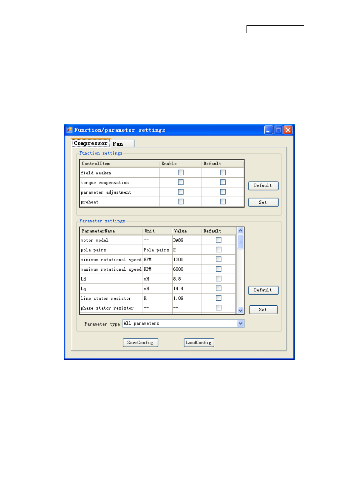
5.4.3
- Name : function/parameter settings window
- Function: motor selection, motor function setting and comeback default,
Function/parameter settings window
motor parameter setting and comeback default, save config file, load config file.
1
2
3
5
Figure 5-5: setting window
6
4
13
Page 15

AN706-00044-1v0-E
Table 5-2: setting window function
Name of area Specification
1 Motor selection Select which motor need to set, compressor / fan
2 Motor function set Function set
3 Motor parameter set Parameter set
4 Parameter type selection Selection motor parameter type
5 Config file save and load Save and load config file
6 Set and default button Set/default the parameter and function to hardware
- Notice:
- The hardware cannot be mounted Fan motor. So the function is ignored.
- Some parameters cannot change the value. (In that case, the parameter is exist as a
constant value in the firmware.)
14
Page 16
AN706-00044-1v0-E
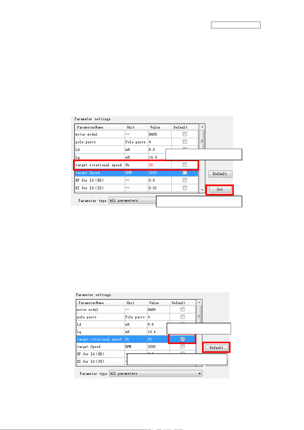
- How to ope
Open this window and you can see the default parameters values.
If you want to change the value, after connecting to the board,
(1) Select the parameter
(2) Change the value directly (and the changed value becomes red)
(3) Push “set” button on the right.
(4) Be sent the value to MCU and set it.
ration of “Function/parameter settings window”
Selected and changed value
Set button for parameter setting
If you want to change the default value, after connecting to the board,
(1) Select the parameter
(2) Check “default” button (and fill the checking symbol in the box)
(3) Push “default” button on the right.
(4) Be sent the default value to MCU and set it.
The default values are saved on the configuration files.
You can change the default value to load the configuration file.
Checked default box
Default button for parameter setting
15
Page 17
AN706-00044-1v0-E
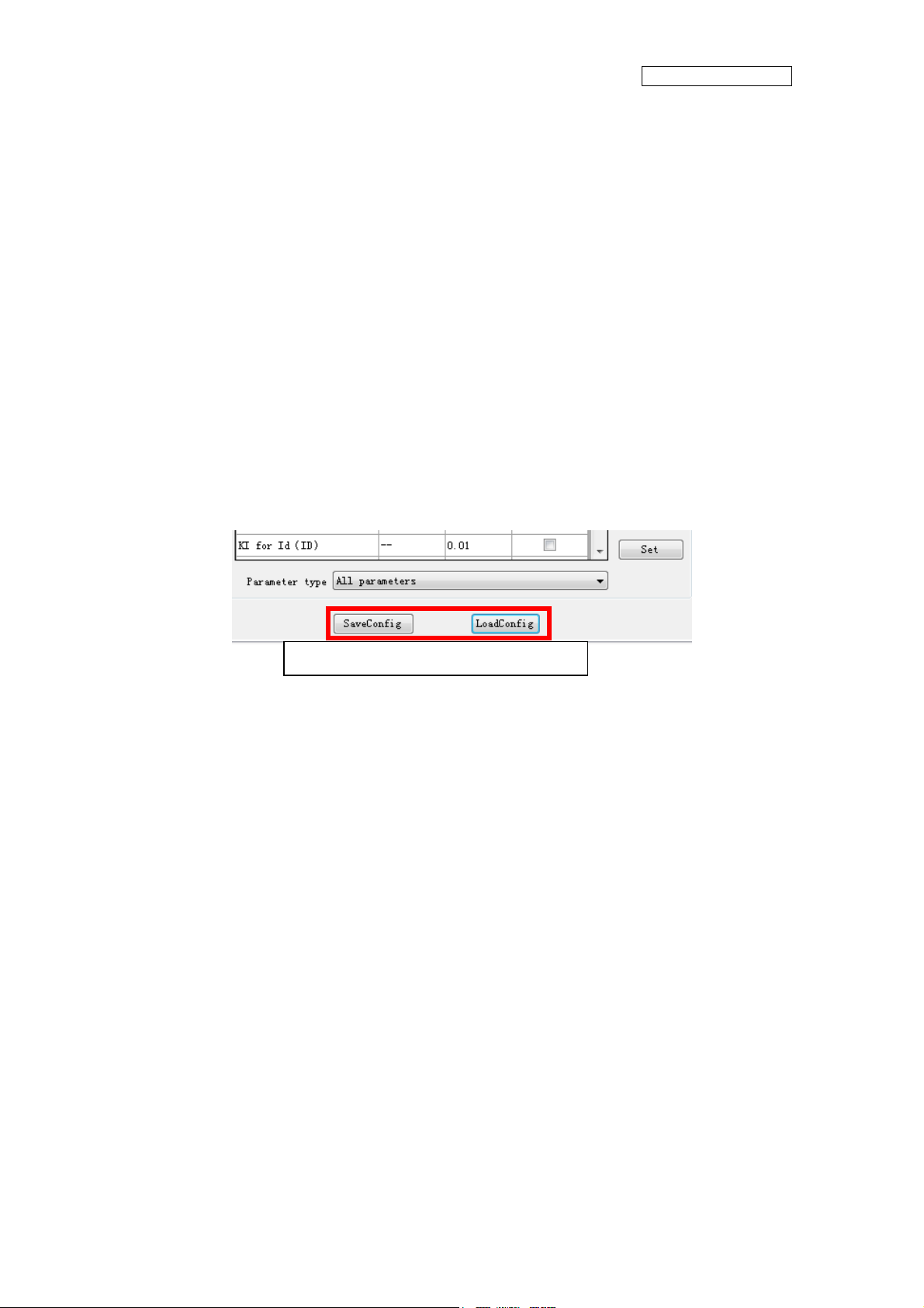
If you want to save the setting value, after
parameters,
(1) Push “saveconfig” button under the window.
(2) Select the saving folder and name the .aip file
(3) Push save button and the configuration file is saved.
If you want to load the configuration file, after connecting to the board,
(1) Push “loadconfig” button under the window.
(2) Select the loaded .aip file
(3) Push open button and the configuration file is loaded.
Saveconfig and Loadconfig button
connecting to the board and setting some
Some p
maximum or minimum value automatically.
arameters can be set as an over-range value, but the firmware can modify as a
16
Page 18

AN706-00044-1v0-E
5.4.4
- Name : select signal window
- Function: signal page selection, signal selection, signal type select, selected signal
shown and some button
Signal selection window
1
2
3
4
Figure 5-6: select signal window
5
17
Page 19

Table 5-3: select signal function
Name of area Specification
AN706-00044-1v0-E
1 Signal page selection
2 Available signals
3 Selected signal type
4 selected signals
5 Operation button
Select the signal page
Select the signal
(most 4 signals in wave, most 10signals in variable )
Select the signal type
Show the selected signals
Set / cancel. If the button is selected,
Figure4.4-5 of the graphic window opens. (See Chapter 4.4.4)
- Notice:
- This window can select compressor contents. System and Fun contents cannot be
selected.
- How to operate Signal selection window
Please refer the chapter “Example of total operating Procedure”
18
Page 20

AN706-00044-1v0-E
5.4.5 Graphic
- Name : wave observer window
- Function: window name set, real-time drawing the wave, showing the selection
signal name, setting the wave station, run/pause set, save/load wave data, current
state.
window
1
2
4
3
Figure 5-7: wave observer window
5
6
7
19
Page 21

AN706-00044-1v0-E
Table 5-4: wave observer function
Name of area Description
1 Form name Custom the name of this wave window.
2 Show wave Draw the wave of signal needing to show.
3 Waveform name Shown the waveform name, it’s come from select signal
4 Select signal
5 Wave setting
6 Other function Pause/run and save/load wave data.
7 System current state Show the current state: connect, PFC, compressor, Fan
Select the signal to show the wave If the button is clicked, the signal
selection window opens. (See Chapter4.4.3)
Select waveform; set waveform color; set the X-grid, Y-grid;
waveform up, down, left, right move; and all setting reset.
- Notice:
- This window can select compressor contents. System and Fun contents cannot be
selected.
- Wave save and load function are not prepared.
- How to operate Signal selection window
Please refer the chapter “Example of total operating Procedure”, too
You can select the data to show the waveform.
The selected parameters are defined wave A through wave D in order.
After selecting, the waveforms are shown the window. As a default, each reference lines
are defined as follows;
20
Page 22

Reference line of Wave A
Reference line of Wave B
Reference line of Wave C
Reference line of Wave D
AN706-00044-1v0-E
ou can change the waveform color each other.
Y
Select the waveform you want to change at the select wave menu.
Then, choose Wave Color button and select the color you want to change.
21
Page 23

AN706-00044-1v0-E
Also, you ca
Select the waveform you want to adjust at the selectwave menu, and push the up / down
arrow button, so the waveform can be adjusted.
You can adjust the X and Y grid unit each other.
Set the value in the X and Y gird box directly, you can set them.
When you select one waveform, you can see the unit under the window. But when you
select over two waveforms, you cannot see it. If you want to confirm the unit, please select
n adjust the waveform position each other.
one wave by select wave pull-down menu and you can see the unit on the right of Y-grid
box.
22
Page 24

AN706-00044-1v0-E
5.4.6 V
- Name:variable observation window.
- Function: show the signal value, select signal.
ariable window
1
2
Figure 5-8: variable observation window
Table 5-5: variable observation function
Name of area Specification
1 Variable value Show the value form hardware
2 Select signal button Into select the signal window
- Notice:
- This window can select compressor contents. System and Fun contents cannot be
selected.
23
Page 25

AN706-00044-1v0-E
5.4.7 Const
- Name : Constant observation window
- Function: show the signal value; select signal.
ant window
1
2
Figure 5-9: Constant observation window
Table 5-6: Constant observation function
Name of area Specification
1 Select page Select need to show page
2 Parameter constant Show the constant about parameter
- Notice:
- This window can be shown compressor contents. Fun contents cannot be shown.
24
Page 26

AN706-00044-1v0-E
5.5 Example of total operating Procedure
This chapter introduces the operating method of GUI.
5.5.1 Hardware preparation
Before operating GUI, prepare hardware according to the following procedure.
1. Install the FTDI driver (Only once)
2. Prepare the hardware environment
3. Connect the wires among the hardware board, FTDI device, PC and so on.
4. Turn on the Hardware power.
5.5.2 GUI software operating step
The following part is an example of GUI operating method.
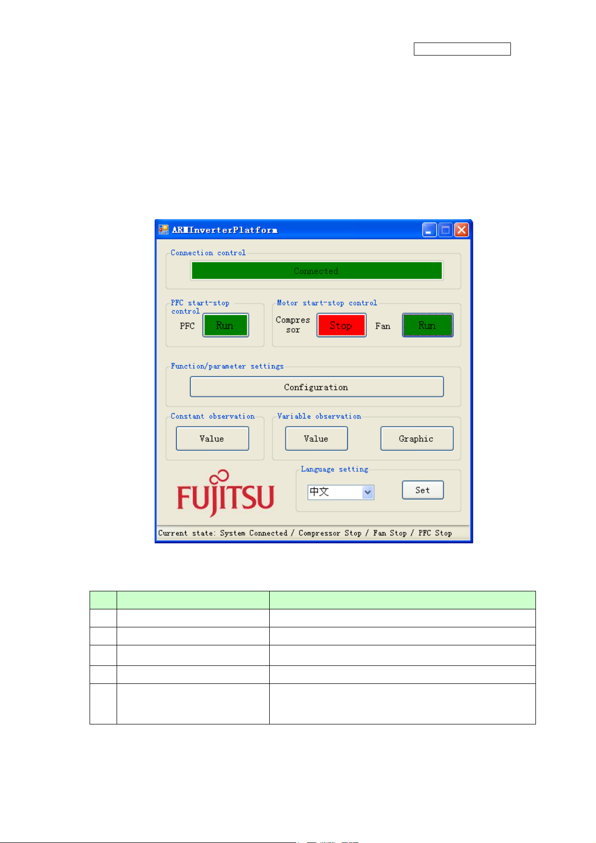
(1) PC and hardware communication Connect:
First, click Connect button in Main Window to connect PC with hardware (1 in
5-10). If connection succeeds, the color of Connect button changes from red to
green. The button text changes from Disconnect to Connected.
Figure
25
Page 27

1
AN706-00044-1v0-E
Figure 5-10: operation: connect
26
Page 28

AN706-00044-1v0-E
Start running the motor
(2)
Next, click Compressor Start-stop Control button in Main Window to start the
motor (1 in the
Control button changes from green to red. The button text changes from Run to
Stop.
Figure 5-11). If succeeds, the color of Compressor Start-stop
1
Figure 5-11: operation: run compressor
27
Page 29

AN706-00044-1v0-E
(3) Set the motor function/parameter
To set the function/parameter of motor, click Function/Parameter Setting button in
Main Window (1 in
displayed.
Figure 5-12), and the Configuration Window in Figure4.5-4 is
1
Figure 5-12: operation: open configuration window
The following example shows the operation of changing motor speed.
Select Compressor tab in Function/parameter Settings window (1 in
Figure 5-13).
To change the motor speed, select All Parameters or Motor Running Parameter in
Parameter type (2 in
Input the speed value to be changed in Value cell (3 in
button and the value is changed (4 in
Figure 5-13). Find Target Speed in Parameter Name column.
Figure 5-13). Then, click Set
Figure 5-13).
28
Page 30

1
AN706-00044-1v0-E
3
2
Figure 5-13: operation: set compressor parameter
4
29
Page 31

(4) Show the wave
AN706-00044-1v0-E
To display the waveform, click Graphic button in Main Window (1 in
the Graphic Window in
Figure 5-15 is displayed.
1
Figure 5-14), and
Figure 5-14: operation: open the wave window
30
Page 32

AN706-00044-1v0-E
1
Figure 5-15: operation: open the select signal window
Click Select Signal button (1 in
and the Signal Selection Window in
Figure 5-15) to select the signal for waveform display,
Figure 5-16is displayed.
The following example shows the waveform display of U, V, and W phase current.
Select Compressor tab in Signal Selection Window (1 in
Current signal or All signals in Signal type (2 in
Figure 5-16). Check the Selection
checkboxes of U-current, V-current, and W-current (3 in
make sure that the signal is selected (4 in
in
Figure 5-16). The Graphic Window of Figure 5-17 is displayed and the waveform
Figure 5-16). After that, click OK button (5
Figure 5-16). Select
Figure 5-16). At this time,
can be observed in real time.
31
Page 33

1
AN706-00044-1v0-E
3
4 5
Figure 5-16: operation: select signal
32
Page 34

AN706-00044-1v0-E
Figure 5-17: operation: draw the waveform
33
Page 35

AN706-00044-1v0-E
6 Appendix
6.1 Particular Install steps about the communication Driver
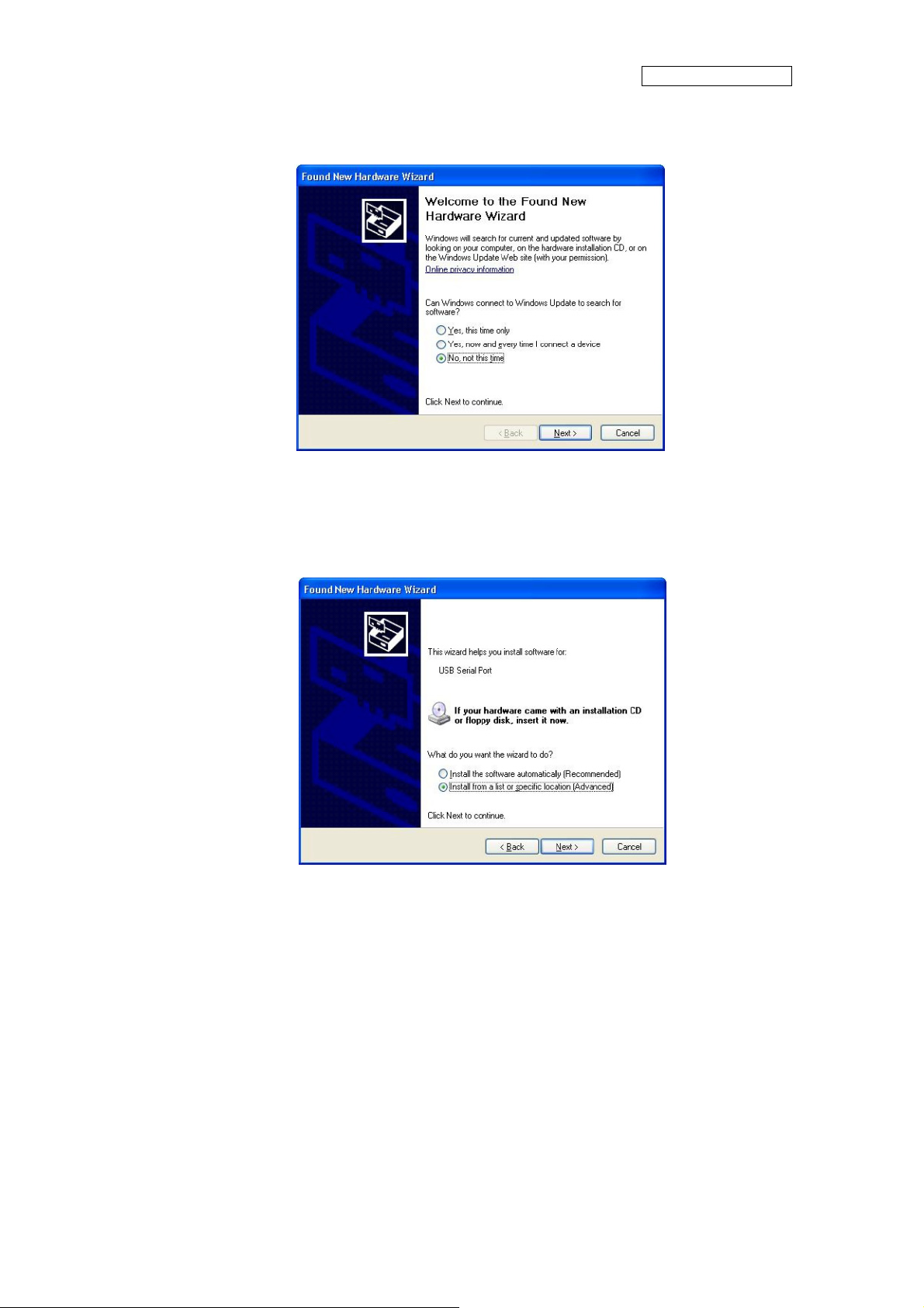
6.1.1 To install FTDI device in Windows XP
- Copy and unzip the FTDI driver on the PC.
- Connect the device to spare USB port on the PC. If the device is based on the
FT2232, the Microsoft composite device driver is automatically loaded in the
background. Once the composite driver has been installed Windows Found New
Hardware Wizard will launch. If there is no available Internet connection or
Windows XP SP 2 is configured to ask before connecting to Windows Update, the
screen shown in Figure 3-1 is displayed. Select "No, not this time" from the options
available and then click "Next" to proceed with the installation. If there is an
available Internet connection, Windows XP will silently connect to the Windows
Update website and install any suitable driver it finds for the device in preference to
the driver manually selected.
Figure 6-1
- Select "Install from a list or specific location (Advanced)" as shown in Figure 3-2
below and then click "Next".
34
Page 36

Figure 6-2
AN706-00044-1v0-E
- Select "Search for the best driver in these locations" and enter the file path in the
combo-box ("¥CDM 2.02.04" in Figure 2.3 below) or browse to it by clicking the
browse button. Once the file path has been entered in the box, click next to
proceed.
Figure 6-3
- If Windows XP is configured to warn when unsigned (non-WHQL certified) drivers
are about to be installed, the message dialogue shown in Figure 3-4 will be
displayed unless installing a Microsoft WHQL certified driver. Click on "Continue
35
Page 37

AN706-00044-1v0-E
Anyway" to continue with the installation. If Windows XP is configured to ignore file
signature warnings, no message will appear.
Figure 6-4 warning
- The screen shown in Figure 3-5 will be displayed as Windows XP copies the
required driver files.
Figure 6-5
- Windows should then display a message indicating that the installation was
successful (Figure 3-6). Click "Finish" to complete the installation for the first port
of the device.
36
Page 38

Figure 6-6
AN706-00044-1v0-E
- If the device is based on the FT2232, the Found New Hardware Wizard will continue
by installing the USB Serial Converter driver for the second port of the FT2232
device. The procedure for installing the second port is identical to that for installing
the first port from the first screen of the Found New Hardware Wizard. This is done
automatically if the driver is Microsoft WHQL certified. If the device is not based on
the FT2232, the COM port emulation driver is loaded as indicated in the following
steps.
- The Found New Hardware Wizard will launch automatically to install the COM port
emulation drivers. As above, select "No, not this time" From the options and click
"Next" to proceed with the installation (Figure 3-7).
37
Page 39
AN706-00044-1v0-E
Figure 6-7
- Select "Install from a list or specific location (Advanced)" as shown in Figure 2.8
below and then click "Next".
Figure 6-8
- Select "Search for the best driver in these locations" and enter the file path in the
combo-box ("¥CDM 2.02.04" in figure 3-9 below) or browse to it by clicking the
browse button. Once the file path has been entered in the box, click next to
proceed.
38
Page 40

Figure 6-9
AN706-00044-1v0-E
- If Windows XP is configured to warn when unsigned (non-WHQL certified) drivers
are about to be installed, the message dialogue shown in Figure 3-10 will be
displayed unless installing a Microsoft WHQL certified driver. Click on "Continue
Anyway" to continue with the installation. If Windows XP is configured to ignore file
signature warnings, no message will appear.
Figure 6-10 warning
- The screen shown in Figure 3-11 will be displayed as Windows XP copies the
required driver files.
39
Page 41

Figure 6-11
AN706-00044-1v0-E
- Windows should then display a message indicating that the installation was
successful (Figure 3-12). Click "Finish" to complete the installation for the first port
of the device.
Figure 6-12
- If the device is based on the FT2232, the second port must also be installed. The
procedure for installing the second port is identical to that for installing the first port
from the first screen of the Found New Hardware Wizard for the USB Serial Port
device. If the driver is Microsoft WHQL certified, this is done automatically.
40
Page 42
AN706-00044-1v0-E
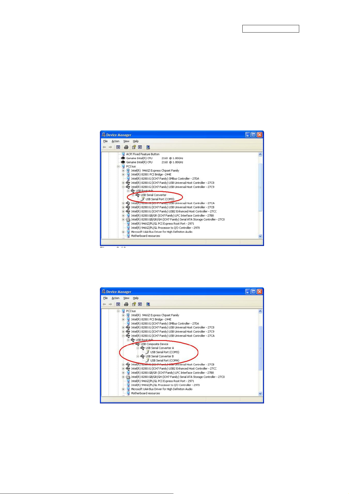
- Open the Device Manager (located in "Control Panel¥System" then select the
"Hardware" tab and click "Device Manger") and select "View > Devices by
Connection", the device appears as a "USB Serial Converter" with an additional
COM port with the label "USB Serial Port" (Figure 3-13). If the device is based on
the FT2232, two ports will be available from a composite USB device.
Figure 6-13
In the case of the FT2232, port A of the FT2232 will be installed as COMX and port B
-
will be installed as COMX+1 where COMX is the first available COM port number.
Figure 6-14
41
Page 43

AN706-00044-1v0-E
6.1.2
FTDI Drivers Installation guide for Windows 7
- Connect the device to a spare USB port on your PC.
- If there is an available Internet connection, Windows 7 will silently connect to the
Windows Update website and install any suitable driver it finds for the device. If the
automatic installation takes place there is no need to continue with the procedure
outlined below. If no suitable driver is automatically found then the following
procedure should be followed. Press the Windows start button to bring up the start
menu and select “Control Panel”.
Figure 6-15
- From the Control Panel window select Hardware and Sound.
42
Page 44

AN706-00044-1v0-E
Figure 6-16
- t the next screen select Device Manager:
A
Figure 6-17
- In the Device Manager window there will be a device under Other Devices with a
yellow w
arning symbol to indicate a problem ie no driver installed. The text next to
this device will depend on the device attached. In this example the device was a
TTL232R device.
43
Page 45

Figure 6-18
AN706-00044-1v0-E
- Right click on the other device (TTL232R in this example) to bring up a menu as
shown below.
Figure 6-19
From the displayed menu select “Update Driver Software…” This then displays the
option for an automatic search or a manual search.
44
Page 46

AN706-00044-1v0-E
Figure 6-20
45
Page 47

Select the second option to browse manually.
-
AN706-00044-1v0-E
Figure 6-21
- In the address box put the exact location where the drivers have been saved to. This
may be on a CD or in a folder on the PC. It is not necessarily the exact same
location as shown in the screenshot. The drivers could have been saved anyw
of the users choosing. After entering the address select “NEXT” to start the
installation.
here
46
Page 48

AN706-00044-1v0-E
Figure 6-22
- When the installation has finished a completion screen is displayed.
47
Page 49

AN706-00044-1v0-E
Figure 6-23
- Press Close button to close this window and go back to the Device Manager
Window.
48
Page 50

AN706-00044-1v0-E
Figure 6-24
The Device Manager will still show a device under Other Devices but in addition to this there
is a new entry under Universal Serial Bus Controllers indicated in the screenshot above as
the USB Serial Converter. This indicates the bus layer of the driver is installed. Installing the
Virtual Com Port layer of the driver is almost a repeat of the last few steps.
- Right click on the other device (TTL232R in this example) to bring up a menu as
shown below.
49
Page 51

AN706-00044-1v0-E
Figure 6-25
- From the displayed menu select “Update Driver Software…” This then displays the
option for an automatic search or a manual search.
50
Page 52

AN706-00044-1v0-E
Figure 6-26
- Select the second option to browse manually.
Figure 6-27
51
Page 53

AN706-00044-1v0-E
In the address box put
the exact location where the drivers have been saved to. This may be
on a CD or in a folder on the PC. It is not necessarily the exact same location as shown in
the screenshot. The drivers could have been saved anywhere of the users choosing.
- After entering the address select “NEXT” to start the installation.
Figure 6-28
52
Page 54

AN706-00044-1v0-E
- When the installation is finished a completion screen is displayed.
Figure 6-29
- Note this screen also displays the COM port assigned to the device. Press Close
button to close this window and go back to the Device Manager Window.
53
Page 55

AN706-00044-1v0-E
Figure 6-30
This time the Device Manager does not have a TTL232R entry under Other Devices but
does show entries under Universal Serial Bus Controllers and Ports (COM & LPT). The
above screen shot displays a correct installation. The device is now ready to use on COM3.
NOTE: Not all devices will install to COM3. The COM port allocation is determined by the
installation wizard on the basis of the next free com port as designated in the PC registry.
54
Page 56

AN706-00044-1v0-E
6.2 Motor parameter item
Table 6-1: motor parameter
Motor parameter name Unit Init Value
compressor model - DA89
pole pairs Pole pairs 2
Ld mh 8.8
Lq mh 14.4
target rotational speed Hz 30
target Speed RPM 1800
KP for Id(KD) - 0.8
KI for Id(ID) - 0.01
KP for Iq(KQ) - 0.8
KI for Iq(IQ) - 0.01
KP for Ω(KS) - 1.2
KI for Ω(IS) - 0.02
minimum rotational speed RPM 1200
maximum rotational speed RPM 6000
d PI max output -
q PI max output -
speed PI max output -
d PI min output -
q PI min output -
speed PI min output -
- End -
55
 Loading...