

Page 1

FUJITSU SEMICONDUCTOR
SUPPORT SYSTEM
SS01-71042-2E
DSU-FR EMULATOR
DSU-FR CABLE
SMALL CABLE For DSU3
MB2198-201
OPERATION MANUAL
Page 2

PREFACE
Thank you for purchasing the DSR-FR cable small cable for DSU3 (MB2198-201, referred to as
"small cable") for the DSU-FR emulator.
The DSR-FR cable small cable for DSU3 is used to connect the DSU-FR emulator (MB2198-01, referred to as "emulator") and the DSU-FR cable (MB2198-10) to a user system.That uses Fujitsu FR
family micro controller (DSU3 Interface loading) to a user system.
This manual explains the handling of the DSR-FR cable small cable for DSU3 for the DSU-FR emulator.
Before using the MB2198-201, be sure to read this manual.
Consult the Sales Department or the Support Department of Fujitsu Limited for mass-produced
MCUs and evaluation MCUs.
■ Handling and use
The handling and use of this product and notes regarding safety are included in the hardware manual
of the DSU-FR emulator and DSR-FR cable operation manual.
Follow the instructions in "DSR-FR EMULATOR MB2198-01 HARDWARE MANUAL"and
"DSR-FR EMULATOR DSR-FR CABLE MB2198-10 OPERATION MANUAL"for the use of this
product.
■ Caution of the products described in this document
The following precautions apply to the product described in this manual.
CAUTION
Cuts
Damage
The wrong use of a device will give an injury and may cause malfunction
on customers system.
This product has parts with sharp points that are exposed.
Do not touch edge of the product with your bare hands.
Please unite correctly the camfering portion of an emu lator interf ace connector , and
the camfering portion of a user system connector.If it mist akes, th ere is a po ssibi lity
of becoming the cause of failure of an emulator system and a user system.
i
Page 3

• The contents of this document are subject to change without notice.Customers are advised to consult with
FUJITSU sales representatives before ordering.
• The information, such as descriptions of function and application circuit examples, in this document are presented solely for the purpose of reference to show examples of operations and uses of FUJITSU semiconductor device; FUJITSU
does not warrant proper operation of the device with respect to use based on such information. When you develop
equipment incorporating the device based on such information, you must assume any responsibility arising out of such
use of the information. FUJITSU assumes no liability for any damages whatsoever arising out of the use of the information.
• Any information in this document, including descriptions of function and schematic diagrams, shall not be construed
as license of the use or exercise of any intellectual property right, such as patent right or copyright, or any other right
of FUJITSU or any third party or does FUJITSU warrant non-infringement of any third-party’s intellectual property
right or other right by using such information. FUJITSU assumes no liability f or any infringement of the intell ectual
property rights or other rights of third parties which would result from the use of information contained herein.
• The products described in this document are designed, developed and manufactured as contemplated for general use,
including without limitation, ordinary industrial use, general office use, personal use, and household use, but are not
designed, developed and manufactured as contemplated (1) for use accompanying fatal risks or dangers that, unless
extremely high safety is secured, could have a serious effect to the public, and could lead directly to death, personal
injury, severe physical damage or other loss (i.e., nuclear reaction control in nuclear facility, aircraft flight control, air
traffic control, mass transport control, medical life support system, missile launch control in weapon system), or (2)
for use requiring extremely high reliability (i.e., submersible repeater and artificial satellite).
Please note that FUJITSU will not be liable against you and/or any third party for any claims or damages arising in
connection with above-mentioned uses of the products.
• Any semiconductor devices have an inherent chance of failure. You must protect against injury, damage or loss from
such failures by incorporating safety design measures into your facility and equipment such as redundancy, fire protection, and prevention of over-current levels and other abnormal operating conditions.
• If any products described in this document represent goods or technologies subject to certain restrictions on export under the Foreign Exchange and Foreign Trade Law of Japan, the prior authorization by Japanese government will be
required for export of those products from Japan.
©2006 FUJITSU LIMITED Printed in Japan
ii
Page 4

1. Checking the Delivered Product
Before using the DSU-FR cable small cable for DSU3, confirm that the following components are
included in the box:
• Small cable*
• Emulator interface connector *
• Operation manual (Japanese version) :1
• Operation manual (English version, this manual) :1
*1 : Small cable is mounted on user system connector (Type:SICA2P20S (Tokyo Eletech Corpo-
ration).
*2 : It is the connector (Type:SICA2P20HD (Tokyo Eletech Corporation) mounted on a user sys-
tem.
This connector can be purchased separately (Type:SICA2P20HD05 (Tokyo Eletech Corpora-
tion, Five-piece on) ).
This product is used by combining with an optional " DSU-FR EMULATOR (MB2198-01) " (sold
separately) and DSU-FR CABLE (Type:MB2198-10) .
Consult the Sales Department or the Support Department of Fujitsu Limited fo r Evaluation MCUs.
2. Handling Precautions
The Small cable is precision-manufactured to improve dimensional accuracy and to ensure reliable
contact. The header is therefore sensitive to mechanical shock. To ensure correct use of the header
in the proper environment, observe the following points regarding its insertion and removal:
1
2
:1
:1
• T o av oid placing stress on the Emulator interface connector mounted on the user system board
during connecting the small cable.
1
Page 5

3. Notes on Designing
■ Restrictions of PC board for the user sy stem
Once the small cable is connected to the user system, the heights of parts mounted in the space
around the small cable are restricted.
The PC board of the user system must be designed with due consideration given to this restriction.
73.0 mm
45.0 mm
2.7 mm
9.0 mm
Approximately
0.5 mm
6.0 mm *
31.0 mm
( TOP VIEW )
70.0 mm *
DSR-FR CABLE
USER SYSTEM
( SIDE VIEW )
* : The height differs slightly depending on how the connector are engaged.
Figure 1 Small Cable Dimensions
2
Page 6

■ EMULATOR INTERFACE CONNECTOR footprint design notes
Figure 2 shows the recommended dimensions of the Emulator interface connector footprint mounted
on the PC board of the user system.
The PC board of the user system must be designed with due consideration given to this footprint.
For more information, contact the Tokyo Eletech Corporation.
5.75 mm
4.5 mm
0.5 mm
0.25 mm
2.0 mm
6.0 mm
1.4 mm
+ 0.1
φ0.8 0 mm
Positioning hole
*
7.1 mm
Positioning hole
+ 0.1
φ0.8 0 mm
*
*:The positioning hole (two places) of a connector is prepared on a PC board.
Figure 2 Recommended Dimensions of the F ootprint fo r Mounting the EMULATOR INTERF A CECONNECT OR
3
Page 7

4. Procedure for Connecting the DSU-FR CABLE
■ Connection
Please remove the cable (FPC cable or flat cable) connected to the DSU-FR cable before using this
product.
The case where a small cable is connected, please pull out a movable piece (white portion) with the
FPC cable connector bottom, and push in a plug and a movable piece for a small cable.
MOVABLE PIECE
FPC CABLE CONNECTOR
■ Disconnection
SMALL CABLE
Figure 3 Connecting Small Cable and DSR-FR Cable
The case where a small cable is removed, please pull out a movable piece (white portion) with the
FPC cable connector bottom, and push in removal and a movable piece for a small cable.
4
Page 8

5. Procedure for Connecting the User System
■ Connection
Before using the DSU cable small cable for DSU3,this product is appended mount the supplied Emulation interface connector on the user system.
T o connect the small cable to the user s ystem, match the position of the Camfering portion of an emulator interface connector mounted on the user system with the position of the Camfering portion of
the user system connector mounted in the small cable is united and then insert it perpendicularly (see
Figure4) .
CAMFERING
PORTION
■ Disconnection
USER SYSTEM CONNECTOR
EMULATOR INTERFA C E CONNECTOR
USER SYSTEM
Figure 4 Connecting Small Cable and User System
To remove the small cable, please draw out a user system connector perpendicularly from an emulator interface connector for load not to join the emulator interface connector mounted on the user
system.
5
Page 9
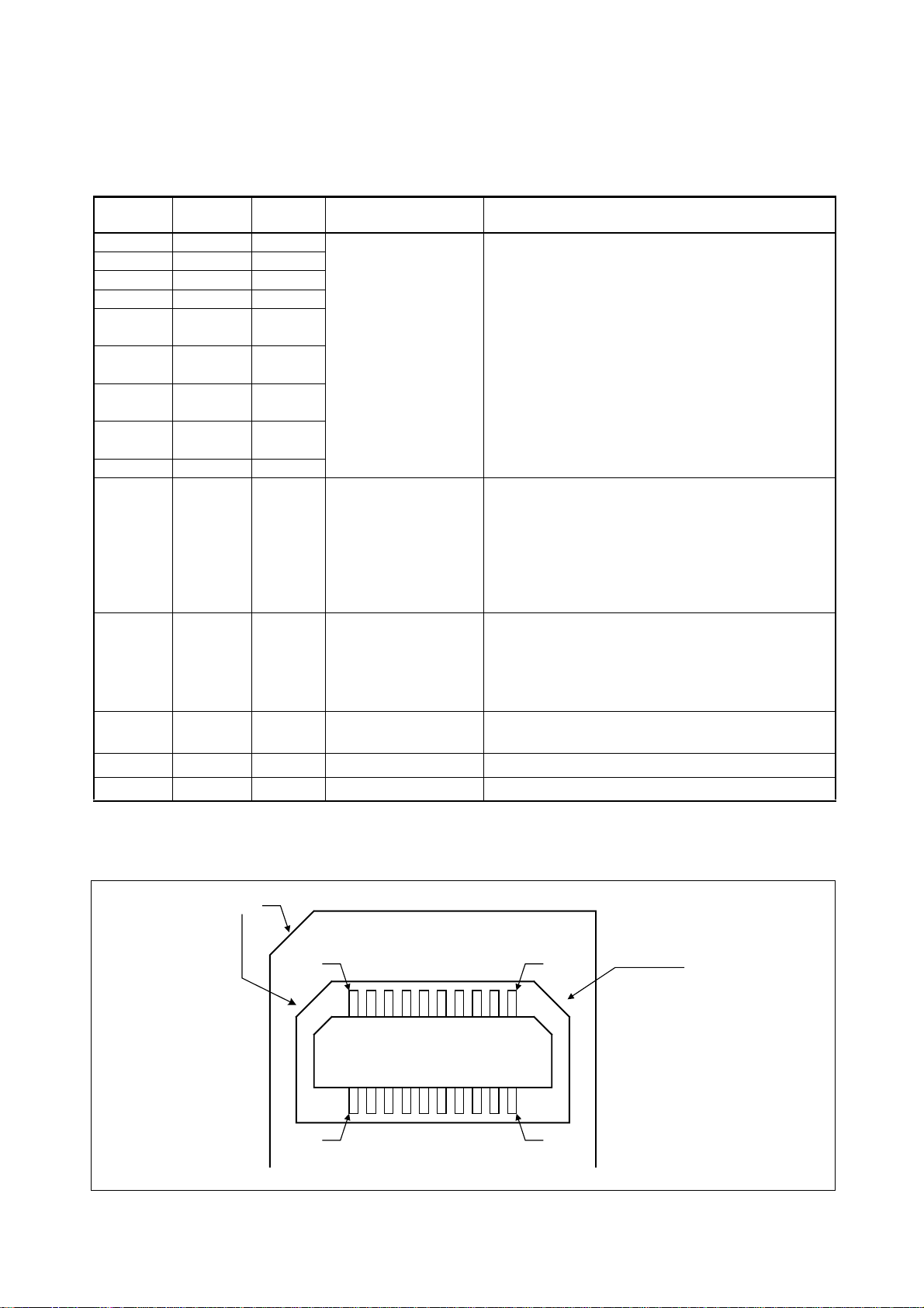
6. User System Connector Pin Assignment
■ Pin assignment
Table 1 User System Connector Pin Assignment
PIN No. PIN name
20 ICLK Input
18 ICS[0] Input
17 ICS[1] Input
16 ICS[2] Input
14 ICD[0]
13 ICD[1]
12 ICD[2]
11 ICD[3]
10 BREAK Output
7 INITX Output Evaluation MCU reset
6 xRSTIN Input User system reset
4
UVcc*
9,15,19 GND - GND
1,2,3,5,8 N.C. - -
Input /
output
Input and
output
Input and
output
Input and
output
Input and
output
Input
Function Description
Emulator control
• Connects with the same name of Evaluation MCU.
• Maximum wiring length is 50 mm.
• Connects with the reset pin of Evaluation MCU.
• Separate wiring between evaluation MCU reset pins-
from the reset output circuit on a user system at thetime of emulator use.
• Effective with the "L" output.
• Open drain output.10 kΩ pull-up resistance built-in
using the UV
• Connects with the reset output circuit of a user system.
• Effective in the "L" input.
(V
(V
User system power supply
• Connects with the external I/O power supply of Evaluation MCU.(0 V to +5.5 V / 100 mA less)
• Connects with the V
• Since it is intact, it opens.
CC pin.(VOL = +0.4 V max, IOL = 12 mA)
IH = +1.7 V min, IIH = −10 µA)
IL = +0.8 V max, IIL = 10 µA)
SS pin (0 V) of Evaluation MCU.
*:When Evaluation MCU is a single power supply, please connect with a V
supplies, connect with an external I/O power supply.
CAMFERING
PORTION
1PIN
2 PIN
Figure 5 User System Connector Form
6
CC pin, and in the case of two or more power
19 PIN
CAMFERING
PORTION
20 PIN
Page 10

SS01-71042-2E
FUJITSU SEMICONDUCTOR • SUPPORT SYSTEM
DSU-FR EMULATOR
DSU-FR CABLE SMALL CABLE For DSU3
MB2198-201
OPERATION MANUAL
February 2006 the second edition
Published FUJITSU LIMITED Electronic Devices
Edited Business Promotion Dept.
Page 11

 Loading...