

Page 1

FUJITSU SEMICONDUCTOR
SUPPORT SYSTEM
F2MC-16 Family EMULATOR
SS01-71045-1E
QFP-100P PROBE HEADER
MB2147-583
OPERATION MANUAL
Page 2
PREFACE
Thank you for purchasing th e QFP -10 0P *1 probe header (MB2147-583) for the F2MC*2 -16 familyemulator.
The QFP-100P probe header is used to connect the F
the F
Fujitsu F
This manual explains the handling of the QFP-100 P probe head er for the F
Before using the MB2147-583, be sure to read this manual.
Consult the Sales representatives or the Support representatives of Fujitsu Limited for mass-produced MCUs and evaluation MCUs.
*1 : The lead pitch of PACKAGE (FPT-100P-M06) is 0.65 mm and the body size is 14 mm × 20
*2 : F
*3 : re ferred to as "em ul ator"
*4 : referred to as "adapter board"
■ Handling and use
The handling and use of this product and no tes regard ing safety are i ncluded in the hard ware manual
of the F
2
2
MC-16L/16LX emulator PGA -299P adapt er boar d (MB214 7-20*4) to a user system. That uses
2
MC *1 -16LX microcontroller MB90940 series (QFP-100P).
MC-16L/16LX emulator (MB2147-01*3)and
2
MC-16 family emulator.
mm. Using the product safely.
2
MC is the abbreviation used for FUJITSU Flexible Microcontroller.
2
MC-16 family emulator.
Follow the instructions in for the use of this product.
2
• F
MC-16L/16LX EMULATOR
MB2147-01 HARDWARE MANUAL
2
• F
MC-16L/16LX EMULATOR PGA-299P ADAPTER BOARD
MB2147-20 HARDWARE MANUAL
■ Caution of the products described in this document
The following precautions apply to the product described in this manual.
The wrong use of a device will give an injury and may cause malfunction on cus-
CAUTION
Cuts
tomers system.
This product has parts with sharp points that are exposed.
Do not touch edge of the product with your bare hands.
When connect the header board to the user system, correctly position the index
Damage
mark (▲) on the NQPACK mounted on the user system with the index mark (▲)
on the header board, otherwise the emulator system and user system might be
damaged.
Damage
When mounting a mass production MCU, correctly position pin 1, otherwise the
mass production MCU and user system might be damag ed.
Page 3

• The contents of this document are subject to change without notice.
Customers are advised to consult with FUJITSU sales representatives before ordering.
• The informati on, such as descriptions of function and application circuit examples, in this document are presented solely for the purpose of reference to show examples of op erations an d uses of FUJITS U semi conducto r devi ce; FUJITSU
does not warrant proper operation of the device with respect to use based on such information. When you develop
equipment incorporating the device based on such information, you must assume any responsibility arising out of such
use of the information. FUJITSU assumes no liab ility for any damages whatsoever arising out of the use of the information.
• Any information in this document, including descriptions of function and schematic diagrams, shall not be construed
as license of the use or exercise of any intellectual property right, such a s pa ten t ri ght or c op yri gh t , or any o the r ri gh t
of FUJITSU or any third party or does FUJITSU warrant non-infringement of any third-party’s intellectual property
right or other right by using such information. FUJITS U assumes no liabil ity for any infringeme nt of the intellectual
property rights or other rights of third parties which would result from the use of information contained herein.
• The products described in this document are designed, developed and manufactured as contemplated for general use,
including without limitation, ordinary industr ial use, genera l office use, personal u se, and household use, b ut are not
designed, developed and manufactured as contemplated (1) for use accompanying fatal risks or dangers that, unless
extremely high safety is secured, could have a serious effect to the public, and could lead directly to death, personal
injury, severe physical damag e or other loss (i.e., nuclear reac tion cont rol in nuclear facility, aircraft flight control, air
traffic control, mass transport control, medical life support system, missile launch control in weapon system), or (2)
for use requiring extremely high reliability (i.e., submersible repeater and artificial satellite).
Please note that FUJITSU will not be liable against you and/or any third party for any claims or damages arising in
connection with above-mentioned uses of the products.
• Any semiconductor devices have an inherent chance of failure. You must protect against injury, damage or loss from
such failures by incorporating safety design measures into y our facility and equ ipment such as redundan cy, fire protection, and prevention of over-current levels and other abnormal operating conditions.
• If any products described in thi s document represen t goods or technol ogies subject to certa in restriction s on export under the Foreign Exchange and Foreign Trade Law of Japan, the prior authorization by Japanese government will be
required for e x por t of th os e pro du c ts fr om J a pan .
©2005 FUJITSU LIMITED Printed in Japan
Page 4

1. Checking the Delivered Product
Before using the QFP-100P probe h eader, confirm that the following components are included in the
box:
• QFP-100P Probe Header
• Screws for securing header board (M2 × 10 mm, 0.4 mm pitch) : 4
• Washer : 4
• NQPACK100RB179
• HQPACK100RB179
• Operation manual (Japanese version) : 1
• Operation manual (English version, this manual) : 1
*1 : Referred to as "header board". Header board is mounted on the YQPACK100RB179 (Tokyo
Eletech Corporation), referred to as “YQPACK”.
*2 : IC socket manufactured by Tokyo Eletech Corporation, referred to as “NQPACK”, and sup-
plied with a special screwdriver and 3 guide pins. A socket offering higher reliability,
NQPACK100RB179-SL (T okyo Eletech Co rporation, so ld separate ly), can be used by making
an IC socket mounting hole on the user system board. For more information, contact Tokyo
Eletech Corporation.
*3 : IC Socket cover manufactured by Tokyo Eletech Corporation, r eferred to as “HQPACK”, with
4 screws for securing HQPACK (M2 × 6 mm, 0.4 mm pitch).
*1
*2
*3
: 1
: 1
: 1
This product is used as an emulator system by combining with an optional emulator and adapter
board.
Consult the Sales Department or the Support Department of Fujitsu Limited for the adapter or the
emulator of this product.
2. Handling Precautions
The header board is precision-manufactured to improve dimensional accuracy and to ens ure reliable
contact. The header is therefore sensitive to mechanical shock. To ensure correct use of the header
in the proper environment, observe the following points regarding its insertion and removal:
• To avoid placi ng stress on the NQPACK mo unted on the user sys tem board during connect ing
the header board.
1
Page 5
3. Notes on Designing
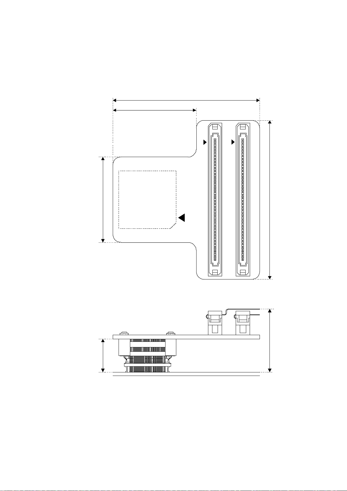
■ Restrictions of PC board for the user system
Once the header board is connected to the user system, the heights of parts mounted in the space
around the header board are restricted.
The PC board of the user system must be designed with du e consideration given to this rest riction
(Figure 1).
40.0 mm
77.0 mm
50.0 mm
CN1
12
CN2
PROBE CABLE CN B2
99 100
12
CN3
PROBE CABLE CN B1
99 100
80.0 mm
Approximately
30.0 mm *
Approximately
13.0 mm *
* : The height differs slightly de pending on how the YQPA CK and the NQPACK are en-
gaged.
Figure 1 Header board dimensions
2
Page 6

■ MCU footprint design notes
Figure 2 shows the recommended dimensions of the NQPACK footprint mounted on the PC board
of the user system.
The PC board of the user system must be designed with due consideration given to this footprint as
well as to the mass production MCU.
For more information, contact the Tokyo Eletech Corporation.
No.1 Pin
0.65
7.0
0.35
6.0
φ 3.2*
UNIT : mm
19.8
2
3 - φ 1.0*
1
2.4
13.8 2.4
*1 : It is a position of hole (φ1.0) for the guide pin to fit position when NQPACK is mounted.
When the guide pin is not used, it is not necessary to puncture it.
*2 : It is a fixation of screw hole(φ3.2) for IC socket made when NQPACK100RB179-
SL(Tokyo Eletech Corporation, sold separately) is mounted.
When the NQPACK100RB179-SL is not used, it is not necessary.
Figure 2 Recommended dimensions of the footprint for mounting the NQPACK
3
Page 7

4. Procedure for Connecting the User System
Before using the QFP-100P probe header, mount the supplied NQPACK on the user system.
The header board is used combining the adapter board. To connect the header board to the adapter
board, use the flat cable (2 lines) supplied by the emulator sold separately. Refer to the hardware
manuals of the adapter board about the way to connect.
■ Connecting
1. To connect the header board to the user system, match the index mark (▲) on the NQPACKmounted on the user system with the index mark (▲) on the header board and then insert it (See
Figure 3) . The pin of YQPACK is thin and easy to bent. Insert NQPACK after confirm that thep
in of YQPACK is not bent.
2. Insert each screw for securing header board in each of the four drilled holes on the header
board(See Figure 4).
To tighten the screws, use the special screwdriver supplied with the NQPACK to finally tightenthe four screws in sequence. Tightening the screws too tight might result in a defective contact.
Probe cable connector B2
YQPACK
(It arranges at the back)
-
Probe cable connector B1
100RB
TET
NQPACK Index (▲)
User System
Header board Index (▲)
Figure 3 Index Position
4
Page 8
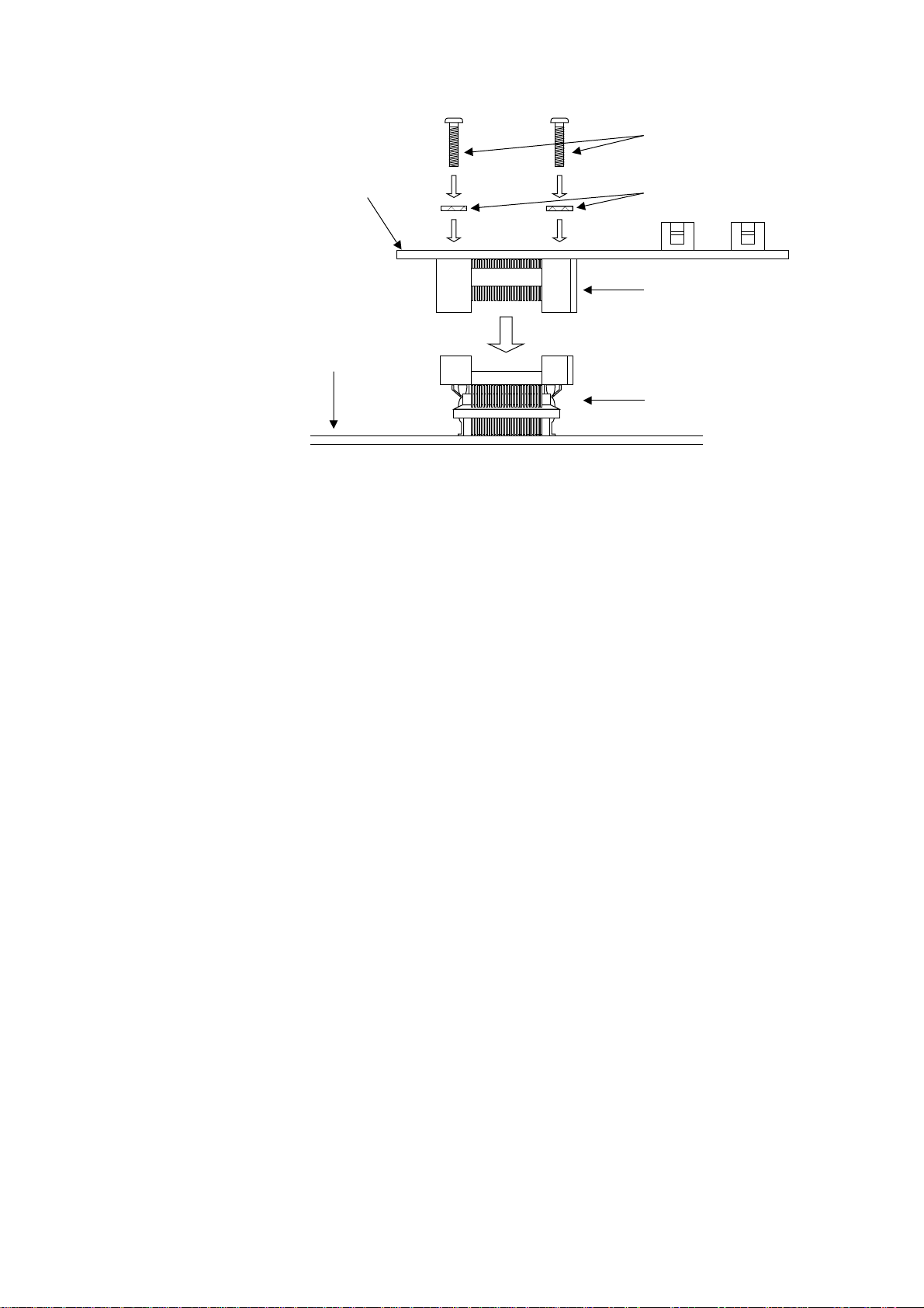
■ Disconnection
Screws for securing
header board
Header board
Washer
YQPACK
User system
NQPACK
Figure 4 Header board connection
To disconnect the header board from the user syst em, remove all four screws, and then pull the header board straight out of the socket
5
Page 9

5. Mounting Mass Production MCUs
To mount a mass production MCU on the user system, use the supplied HQPACK (See Figure 5).
■ Mounting
1. To mount a mass production MCU on the user system, match the index mark (▲) on the NQPACK mounted on the user system with the index mark (●) on the mass production MCU.
2. Confirm that the mass production MCU is correctly mounted on the NQPACK. Next, insert the
HQPACK into a NQPACK.
The pin of HQPACK is thin and easy to bent. Insert NQPACK after confirm that the pin of HQPACK is not bent.
3. Insert each screw for securing HQPACK in each of the four drilled holes on the HQPACK (See
Figure 5).
To tighten the screws, use the special screwdriver supplied with the NQPACK to finally tighten
the four screws in sequence. Tightening the screws too tight might result in a defective contact.
Screws for securing HQPACK
■ Disconnection
HQPACK
Mass production MCU
User system
NQPACK
Figure 5 Mounting a mass production MCU
To remove the HQPACK, remove all four screws, and pull out the HQPACK vertically.
6
Page 10

6. Connector Pin Assignment
The signal of Evaluation MCU with which it was carried on the adapter board is connected to YQPACK(the same assignments as product ion MCU) via the probe cable connector( B1,B2) on a header
board.
An adapter board and a header board are connected to an emulator main part by the attached flat cable (It is used standard 2 or two long.)connector.
Please check the hardware manual of an emulator or an adap ter board ab out reference of the c onnection method.
■ Pin Assignment
Tables 1 and 2 list the pin assignments among the flat cable connector, the evaluation MCU on the
adapter board, and the production MCU.
For details on the names of signal conductors of the evaluation MCU, refer to the hardware manual
for the adapter board.
Comments in the tables are given below.
*1 : Co nnected to the main power supply of the evaluation MCU.
*2 : Conn ected to the mai n power suppl y (Vcc) of the prod uction MCU. The connection pin num-
bers are 15 and 90.
*3 : Connected to the ground of the evaluation MCU.
*4 : Connected to the ground (Vss) of the production MCU. The connection pin numbers are 16,
44 and 91.
- : Unconnected pin (left open).
7
Page 11

Table 1 Pin assignment of the probe cable connector B1
Probe cable-
Connector
Pin
Numbers
100 *3 *4 99 *3 *4
98 *3 *4 97 80 42
96 208 43 95 148 41
94 259 40 93 *3 *4
92 79 39 91 207 38
90 147 37 89 258 35
88 78 36 87 206 34
86 *3 *4 85 77 32
84 146 33 83 160 49
82 223
80 26
78 94 74 77 269 72
76 219 73 75 95 71
74 *3 *4 73 33 63
72 *1 *2 71 169 62
70 226 58 69 *3 *4
68 275 57 67 34 56
66 105 55 65 167
64 224
62 *3 *4 61 225 60
60 274 64 59 32 61
58 104 59 57 *3 *4
56 170 47 55 106 46
54 227 17 53 163 65
52 *3 *4 51 162 70
50 *3 *4 49 96 68
48 220 69 47 270 67
46 100 66 45 *3 *4
44 97
42 164
40 98
38 *3 *4 37 222 76
36 23
34 165
32 276 45 31 107 24
30 108 23 29 277 21
28 172 22 27 109 20
26 *3 *4 25 173 18
24 229 19 23 228 *2
22 130 12 21 *3 *4
20 292 11 19 193 10
18 131 9 17 194 7
16 247 8 15 132 6
14 *3 *4 13 *3 *4
12 293 5 11 61 4
10 248 3 9 *3 *4
8 133 2 7 195 1
6 62 100 5 63 98
4 134 99 3 294 97
2 *3 *4 1 *3 *4
Evaluation
MCU
Pin Numbers
Production
MCU
Pin Numbers
⎯
⎯
⎯
⎯
⎯
⎯
⎯
⎯
Probe cable-
Connector
Pin
Numbers
81 *3 *4
79 268
63 35 48
43 221
41 273
39 271
35 99 75
33 *3 *4
Evaluation
MCU
Pin Numbers
Production
MCU
Pin Numbers
⎯
⎯
⎯
⎯
⎯
8
Page 12

Table 2 Pin assignment of the probe cable connector B2
Probe cable-
Connector
Pin
Numbers
100 *3 *4 99 *3 *4
98
96 *3 *4 95 217 14
94 267 13 93 *3 *4
92 149 25 91 81 26
90 260 27 89 82 29
88 209 28 87 83
86 *3 *4 85 87
84 218
82 263
80 153
78 8
76 *1 *2 75 84
74 *3 *4 73 272
72 5 31 71 168
70 103
68 166
66 *3 *4 65 210
64 151
62 *3 *4 61 158
60 6
58 92
56 266
54 91
52 215
50 *3 *4 49 88
48 16
46 264
44 213
42 14
40 203
38 *3 *4 37 202
36 299
34 201
32 141
30 110 51 29 230 53
28 278 52 27 262 54
26 *3 *4 25 140 93
24 *3 *4 23 200 92
22 *1 *2 21 *3 *4
20 252 77 19 199 78
18 71 79 17 70 81
16 138 80 15 251 82
14 *3 *4 13 198 84
12 296 83 11 137 85
10 136 86 9 *3 *4
8 197 87 7 295 88
6 250 89 5 64 95
4 135 94 3 196 96
2 *3 *4 1 *3 *4
Evaluation
MCU
Pin Numbers
⎯ ⎯
Production
MCU
Pin Numbers
⎯
⎯
⎯
⎯
⎯
⎯
⎯
⎯
⎯
⎯
⎯
⎯
⎯
⎯
⎯
⎯
⎯
⎯
⎯
⎯
Probe cable-
Connector
Pin
Numbers
97 159 50
83 212
81 *3 *4
79 86
77 150 30
69 *3 *4
67 7
63 261
59 216
57 *3 *4
55 157
53 156
51 155
47 15
45 *3 *4
43 154
41 255
39 143
35 142
33 *3 *4
31 101
Evaluation
MCU
Pin Numbers
Production
MCU
Pin Numbers
⎯
⎯
⎯
⎯
⎯
⎯
⎯
⎯
⎯
⎯
⎯
⎯
⎯
⎯
⎯
⎯
⎯
⎯
⎯
⎯
⎯
⎯
⎯
9
Page 13

SS01-71045-1E
FUJITSU SEMICONDUCTOR • SUPPORT SYSTEM
2
F
MC-16 Family EMULATOR
QFP-100P PROBE HEADER
MB2147-583
OPERATION MANUAL
May 2005 the first edition
Published FUJITSU LIMITED Electronic Devices
Edited Business Promotion Dept.
Page 14

 Loading...