

Page 1

FUJITSU SEMICONDUCTOR
CONTROLLER MANUAL
F2MC-16L/16LX EMULATOR
CM42-00412-1E
MB2147-01
HARDWARE MANUAL
Page 2

Page 3

F2MC-16L/16LX EMULATOR
MB2147-01
HARDWARE MANUAL
FUJITSU LIMITED
Page 4

Page 5

PREFACE
■ Using the product safely
This manual provides important information on using this product safely. Read this manual
carefully before using the product to ensure correct use. In particular, carefully read "Safety
Precautions" in this Preface before using the product so that you understand the requirements
for safe use of the product.
After reading this manual, keep it handy for reference.
■ Objectives and intended readers
The MB2147-01 is a development support tool used to develop and evaluate application
products that use the Fujitsu F
This manual is intended for the engineers who use the MB2147-01 (called the "emulator unit" in
this manual) to develop F
how to handle and connect the emulator unit.
■ Guarantee and liability
The specifications of this product may be changed without prior notice. The publisher assumes
no responsibility for any effect or incident resulting from the operation of this product.
2
MC-16L/16LX microcontroller.
2
MC-16L and F2MC-16LX application products. The manual explains
■ Trademark
2
F
MC is the abbreviation of FUJITSU Flexible Microcontroller.
Other system and product names in this manual are trademarks of respective companies or
organizations.
The symbols
TM
and ® are sometimes omitted in this manual.
i
Page 6
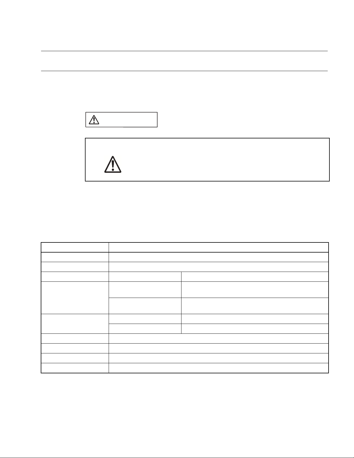
■ Safety precautions
The table below lists important precautions contained in this manual and the pages on which
they occur.
Before using the product, read these pages so that you fully understand the requirements for
safe use of the product.
This symbol indicates that incorrect use of the product may result in death
WARNING
Warning Description Page
or serious injury to the user.
Electric shock
Plug
No disassembly
Do not touch the inside of a connector port. Doing so may result in electric
shock or device problems.
If the product emits excessive heat, smoke, an offensive smell, or an
unusual noise, turn off power immediately. Then, disconnect the power
plug from the outlet. If smoke was detected, make sure that no more smoke
is coming from the product. Then, contact our sales or support department
to request that the product be repaired. Do not attempt to repair the product
by yourself. Otherwise, personal injury, damage to the product, or other
property damage may result. Using such a product without having it
properly repaired may result in fire or electric shock.
If water or other liquid, a metallic object, or other foreign matter enters the
product, immediately turn off power, and disconnect the power plug from
the outlet. Then, consult with our sales or support department. Using the
product under such abnormal conditions may result in device problems,
fire, or electric shock.
Disconnect the power plug during electrical storms. Using the product
during an electrical storm may result in damage to the product or fire.
Do not open the product case. Do not modify the product without
permission. Doing so may result in device problems, fire, or electric shock.
16
15
15
16
16
No moisture
ii
Do not use the product near water such as near a bath or shower. Doing so
may result in device problems, fire, or electric shock.
16
Page 7
This symbol indicates that incorrect use of the product may result in death
WARNING
Warning Description Page
or serious injury to the user.
Prohibition
Do not touch the product with wet hands. Doing so may result in electric
shock.
Do not place the product in a location exposed to excessive moisture or
dust or in a poorly ventilated location. Do not place the product near an
open flame. Doing so may result in device problems, fire, or electric shock.
Do not block the product ventilation holes. Doing so may cause generation
of excessive heat, possibly resulting in a fire.
Do not insert metallic, combustible, or other objects or allow them to drop
into the product through a ventilation hole or other opening. Doing so may
result in device problems, fire, or electric shock.
Do not use a voltage other than the indicated value of supply voltage. Do
not connect power cable together with too many plugs to an outlet. Doing
so may result in fire or electric shock.
The product must not be scratched, modified, forcibly bent, pulled, twisted,
or exposed to heat. Do not place heavy objects on the product. Doing so
may result in device problems, fire, or electric shock.
Do not use the product if it has a fault, damage, or sever wires in the cable.
Doing so may result in fire or electric shock.
17
17
17, 19
17
17
17
19
iii
Page 8
This symbol indicates that incorrect use of the product may result in minor
CAUTION
Warning Description Page
or moderate injury to the user, in damage to the product and any devices
connected to it, or in the destruction of data and other software resources
or other property.
Plug
Prohibition
Disconnect the power plug before moving the product. Disconnect all other
connected cables. Exercise caution when working near cables on the floor.
Damage to a cable may result in fire or electric shock. A falling device may
result in injury.
If the product is not to be used for an extended period, disconnect the
power plug. Doing so may result in fire or electric shock.
Do not place the product in a location exposed to shock or a location that is
not level or stable. Doing so may result in device problems or the product
falling over or falling on the floor.
Do not grasp the cable when unplugging the power plug and cable. Always
grasp the power plug or connector itself. Pulling the cable may expose
conductors or sever wires in it, possibly resulting in device problems, fire,
or electric shock.
Do not place the product in a location, such as near a speaker or television
tuner, where it is exposed to an electromagnetic field. Doing so may result
in device problems.
Make sure that power to the product is turned off and the power plug is
disconnected from outlets before connecting or disconnecting cables,
removing or mounting boards, handling switches or jumpers, or mounting
parts (unless such an operation uses USB cables for plug-and-play
devices). Doing so may result in device problems or electric shock.
18
18
18
18, 19,
25, 26,
27, 28,
29, 30,
31, 32
18
19
To prevent device damage by electrostatic discharge, do not touch, and do
not let any object contact pins of connectors or other parts of the product.
Before handling the product, be sure to discharge static electricity from
your body by touching a metallic object, such as doorknob. Doing so may
result in device problems.
Do not apply any shock to this product. Doing so may result in device
problems.
Do not expose the product to direct sunlight, and do not place it where it is
hot and humid. Do not allow condensation to form on the product.
Do not store the product in a dusty location. Doing so may result in device
problems.
Do not store the product where it is exposed for a long time to relatively
strong electric or magnetic fields. Because the product uses many
electronic components, problems may result.
19
20
20
20
20
iv
Page 9
This symbol indicates that incorrect use of the product may result in minor
CAUTION
Warning Description Page
or moderate injury to the user, in damage to the product and any devices
connected to it, or in the destruction of data and other software resources
or other property.
Prohibition
Make sure that power to the product is turned off and the power plug is
disconnected from outlet before removing or mounting boards. Doing so
may result in device problems or electric shock.
When mounting a board, make sure that it is mounted in the proper
direction. Doing so may result in device problems.
Do not apply pressure on one part of a board when mounting the board.
Attempt to distribute equal pressure on the entire board. Doing so may
result in damage to the board.
Make sure that power to the product is turned off and the power plug is
disconnected from outlets before connecting or disconnecting cables.
Doing so may result in device problems or electric shock.
Make sure that power to the product is turned off and the power plug is
disconnected from outlets before connecting or disconnecting cables
(unless such an operation uses USB cables for plug-and-play devices).
Doing so may result in device problems or electric shock.
Make sure that power to the product is turned off and the power plug is
disconnected from outlets before mounting the evaluation MCU. Doing so
may result in device problems or electric shock.
Make sure that power to the product is turned off and the power plug is
disconnected from outlets before mounting crystal unit or handling switches
or jumpers. Doing so may result in device problems or electric shock.
23
23
23
25, 26, 27,
28, 29, 31,
32
30
34
35
Make sure that power to the product is turned off and the power plug is
disconnected from outlets before handling jumpers. Doing so may result in
device problems or electric shock.
Make sure that power to the product is turned off and the power plug is
disconnected from outlets before handling switches. Doing so may result in
device problems or electric shock.
Follow the procedure described in the manual to turn on the product. Doing
so may result in device problems.
After power is turned on to the product, do not move the system, or apply
any shock or vibration to it. Doing so may result in device problems.
Follow the procedure described in the manual to turn off the product. Doing
so may result in device problems.
38, 40
41, 42
47
47
49
v
Page 10
This symbol indicates that incorrect use of the product may result in minor
CAUTION
Warning Description Page
or moderate injury to the user, in damage to the product and any devices
connected to it, or in the destruction of data and other software resources
or other property.
Attention
Caution
To re-transport the product, use the package used at the delivery, and pack
them as it was packed. Doing so may result in damage to the product.
Insert the power plug so that the connection is secure. Doing so may result
in device problems or fire.
Use the product according to its specifications. Doing so may result in
device problems.
2
18, 32
5
vi
Page 11

■ Organization of this Manual
This manual consists of three chapters. Be sure to read the manual before using the emulator.
CHAPTER 1 "PRODUCT HANDLING AND SPECIFICATIONS"
This chapter gives an overview, including specifications, and explains how to handle the
emulator.
Before using the emulator, be sure to read this chapter and check the packed components of
the emulator.
CHAPTER 2 "CONNECTING THE EMULATOR"
This chapter explains how to connect the emulator.
Read this chapter before turning on the emulator.
CHAPTER 3 "OPERATING THE EMULATOR"
This chapter explains basic operations of the emulator.
Read this chapter before turning on the emulator.
■ Related manuals
Also read the following manuals:
• Hardware Manual of the evaluation MCU used
• Adapter Board Hardware Manual
• Operation Manual of the probe cable used
• Operation Manual of the probe header used
• Softune Workbench Operation Manual
vii
Page 12

• The contents of this document are subject to change without notice. Customers are advised to consult
with FUJITSU sales representatives before ordering.
• The information and circuit diagrams in this document are presented as examples of semiconductor
device applications, and are not intended to be incorporated in devices for actual use. Also, FUJITSU is
unable to assume responsibility for infringement of any patent rights or other rights of third parties
arising from the use of this information or circuit diagrams.
• The products described in this document are designed, developed and manufactured as contemplated
for general use, including without limitation, ordinary industrial use, general office use, personal use, and
household use, but are not designed, developed and manufactured as contemplated (1) for use
accompanying fatal risks or dangers that, unless extremely high safety is secured, could have a serious
effect to the public, and could lead directly to death, personal injury, severe physical damage or other
loss (i.e., nuclear reaction control in nuclear facility, aircraft flight control, air traffic control, mass
transport control, medical life support system, missile launch control in weapon system), or (2) for use
requiring extremely high reliability (i.e., submersible repeater and artificial satellite).
Please note that Fujitsu will not be liable against you and/or any third party for any claims or damages
arising in connection with above-mentioned uses of the products.
• Any semiconductor devices have an inherent chance of failure. You must protect against injury, damage
or loss from such failures by incorporating safety design measures into your facility and equipment such
as redundancy, fire protection, and prevention of over-current levels and other abnormal operating
conditions.
• If any products described in this document represent goods or technologies subject to certain
restrictions on export under the Foreign Exchange and Foreign Trade Law of Japan, the prior
authorization by Japanese government will be required for export of those products from Japan.
©2002 FUJITSU LIMITED Printed in Japan
viii
Page 13

CONTENTS
CHAPTER 1 PRODUCT HANDLING AND SPECIFICATIONS ......................................... 1
1.1 Checking Packed Components ............................................................................................................. 2
1.2 Appearance and Part Names ................................................................................................................ 3
1.3 General Specifications ........................................................................................................................... 5
1.4 RS-232C Port Specifications ................................................................................................................. 6
1.5 USB Port Specifications ......................................................................................................................... 7
1.6 LAN Port Specifications ......................................................................................................................... 8
1.7 External Trigger Input Terminal Specifications ...................................................................................... 9
1.8 Program Execution Output Terminal Specifications ............................................................................ 10
1.9 Power-On Debug Specifications .......................................................................................................... 11
1.10 Options ................................................................................................................................................ 13
1.11 Precautions about Possible Problems ................................................................................................. 15
1.12 Precautions on Handling the Product .................................................................................................. 16
1.13 Precautions on Use ............................................................................................................................. 19
CHAPTER 2 CONNECTING THE EMULATOR ............................................................... 21
2.1 System Configuration .......................................................................................................................... 22
2.2 Connecting an Adapter Board ............................................................................................................. 23
2.3 Connecting the User System ............................................................................................................... 24
2.4 Connecting a Probe ............................................................................................................................. 28
2.5 Connecting a Host Machine ................................................................................................................. 30
2.6 Connecting Test Equipment ................................................................................................................ 31
2.7 Connecting the AC Adapter ................................................................................................................. 32
CHAPTER 3 OPERATING THE EMULATOR .................................................................. 33
3.1 Mounting an Evaluation MCU .............................................................................................................. 34
3.2 Clock Supply ........................................................................................................................................ 35
3.3 Emulator-dedicated Power Supply Switching ...................................................................................... 38
3.4 User Port Power Supply Switching ...................................................................................................... 40
3.5 Switching the C Pin Setting ................................................................................................................. 41
3.6 User Data Bus Switching ..................................................................................................................... 42
3.7 Using the Setting Switches .................................................................................................................. 44
3.8 Power-On Sequence ........................................................................................................................... 47
3.9 Power-Off Sequence ........................................................................................................................... 49
ix
Page 14

x
Page 15

CHAPTER 1 PRODUCT HANDLING AND
SPECIFICATIONS
This chapter gives an overview, including specifications, and explains how to handle
the emulator.
Before using the emulator, be sure to read this chapter and check the product
information.
1.1 "Checking Packed Components"
1.2 "Appearance and Part Names"
1.3 "General Specifications"
1.4 "RS-232C Port Specifications"
1.5 "USB Port Specifications"
1.6 "LAN Port Specifications"
1.7 "External Trigger Input Terminal Specifications"
1.8 "Program Execution Output Terminal Specifications"
1.9 "Power-On Debug Specifications"
1.10 "Options"
1.11 "Precautions about Possible Problems"
1.12 "Precautions on Handling the Emulator"
1.13 "Precautions on Use"
1
Page 16
CHAPTER 1 PRODUCT HANDLING AND SPECIFICATIONS
1.1 Checking Packed Components
Before using the emulator unit, check the packed components to make sure that all
components are included.
■ Checking packed components
CAUTION
Attention
Before using the emulator unit, make sure that the packed components include the following:
• Emulator unit: 1 unit
• AC adapter: 1 unit
• AC cord: 1 cord
• Flat cable 1 (standard length): 2 cables
• Flat cable 2 (long): 2 cables
• Hardware manuals (in Japanese and English [this manual]): one in each language
Note:
The AC cord and AC adapter are packed in the same box.
To re-transport the product, use the package used at the delivery, and
pack them as it was packed. Doing so may result in damage to the
product.
2
Page 17
1.2 Appearance and Part Names
1.2 Appearance and Part Names
This section gives the names of all parts of the emulator unit.
■ Appearance and Part Names
Figure 1.2-1 "Top view of the emulator unit" to Figure 1.2-3 "Rear view of the emulator unit"
show the exterior of the emulator unit and give the names of all of its parts.
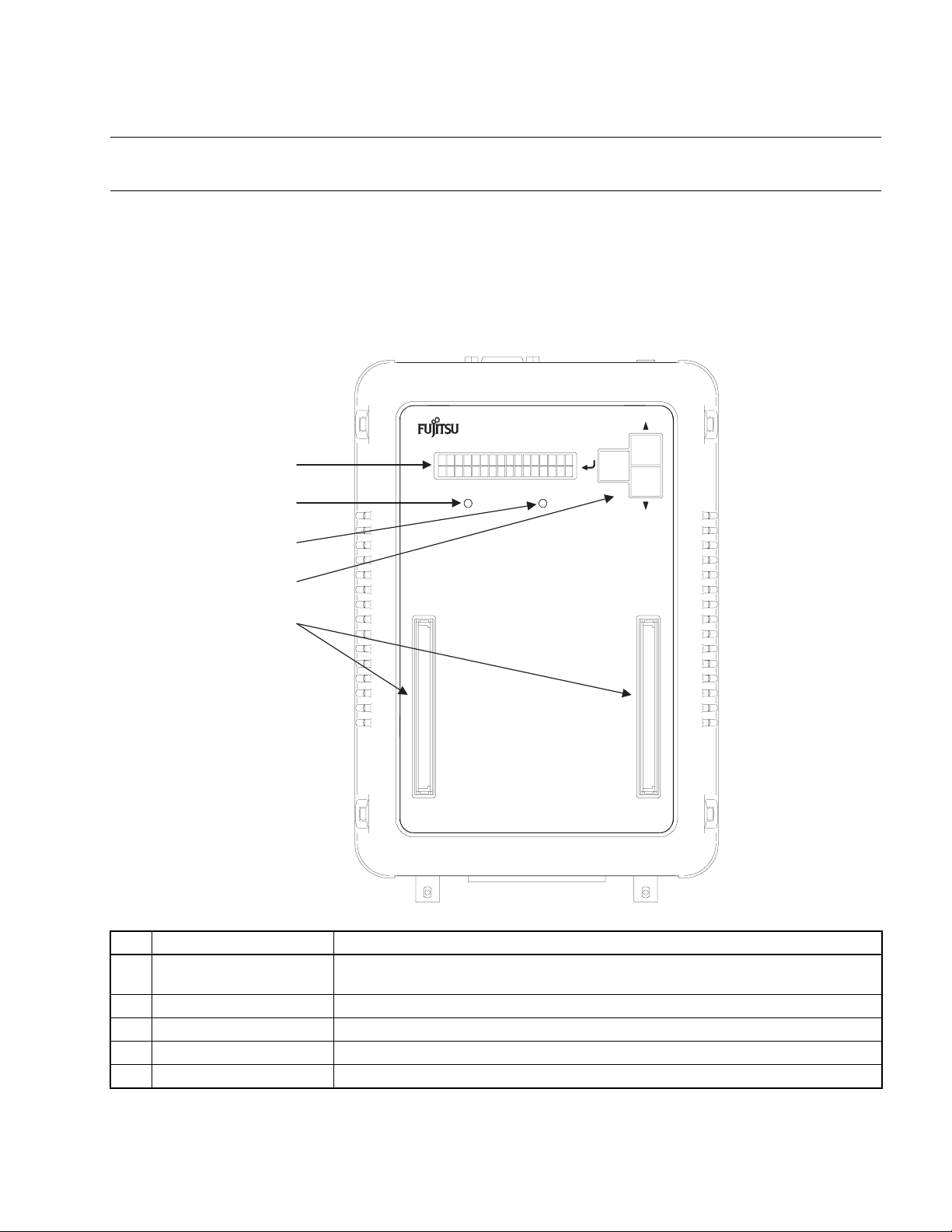
Figure 1.2-1 Top view of the emulator unit
MB2147-01
F2MC-16 SERIES EMULATOR
(1)
(2)
POWER UVCC
(3)
(4)
(5)
No. Name Description
(1) Status indicator LCD
(2) POWER LED Goes on when emulator power is supplied.
(3) UVCC LED Goes on when user system power (UV
(4) Setting switches Used to change settings and the information displayed on the status indicator LCD.
(5) Adapter board connector Connects to an adapter board (option).
*1: For information on the type of information displayed on the status indicator LCD and how to use the setting
switches, see Section
*2: If the evaluation MCU has a dual source power supply, this LED goes on when both power supplies are turned on.
3.7
Displays different kinds of information, including setting values, communication status,
and operating status.
"Using the Setting Switches."
(*1)
) is supplied.
CC
(*2)
(*1)
3
Page 18
CHAPTER 1 PRODUCT HANDLING AND SPECIFICATIONS
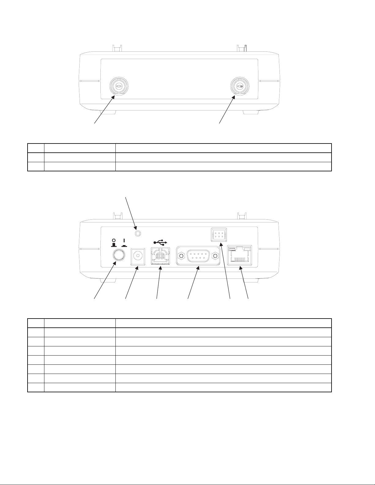
Figure 1.2-2 Front view of the emulator unit
TRIG EMUL
(1)
(2)
No. Name Description
(1) TRIG terminal Used to input external trigger signals.
(2) EMUL terminal Outputs a program execution signal.
Figure 1.2-3 Rear view of the emulator unit
(1)
DC IN
RESET
SERIAL
POWER
(2) (3) (4) (5) (6) (7)
LAN
No. Name Description
(1) RESET switch Resets the emulator.
(2) POWER switch Turns on the emulator.
(3) DC inlet Connects to the AC adapter provided as an accessory.
(4) USB connector Connects to a USB cable.
(5) RS-232C connector Connects to an RS-232C cable.
(6) TEST terminal Connects to a cable used for product testing. Do not use this terminal.
(7) LAN connector Connects to a LAN cable.
4
Page 19
1.3 General Specifications
This section covers the general specifications of the emulator.
■ General specifications
CAUTION
1.3 General Specifications
Caution
device problems.
Table 1.3-1 "General specifications" lists the general specifications of the emulator.
The following names used in this manual have the following definitions:
• Emulator: Emulator unit + adapter board
• Emulator system: Emulator unit + adapter board + probe
Table 1.3-1 General specifications
Item Specification
2
Use the product according to its specifications. Doing so may result in
Name F
Model name MB2147-01
Emulator power supply Power supply input +16 V 2.5 A (supplied using a special AC adapter)
Evaluation MCU power
supply
Operating frequency
Temperature +5 to +35 degrees Celsius
MC-16L/16LX Emulator
Emulator interface power
supply output
User system power supply
input
High-speed I/F 8 KHz to 33 MHz
Conventional interface 8 KHz to 20 MHz
+3.3 V or +5.0 V (supplied from the emulator)
+1.8 V to +5.5 V
supply supported: Supplied from the user system)
(*1)
10 mA or less
(*3)
(*3)
(*2)
(Dual source power
Humidity 20 to 80% (No condensation)
External dimensions 148(W) x 210(D) mm x 44(H) (excluding protruding sections and rubber feet)
Weight 700 g
*1: The upper and lower voltage limits depend on the evaluation MCU used.
For more information, contact the Fujitsu Sales Dept. or Support Dept.
*2: The current consumption of the evaluation MCU is excluded.
*3: The upper and lower frequency limits depend on the evaluation MCU used. The upper and lower frequency limits may
depend on the operating voltage, even if the same evaluation MCU is used. For more information, contact the Fujitsu
Sales Dept. or Support Dept.
5
Page 20
CHAPTER 1 PRODUCT HANDLING AND SPECIFICATIONS
1.4 RS-232C Port Specifications
The emulator includes an RS-232C port.
■ RS-232C port specifications
Table 1.4-1 "RS-232C port specifications" lists the RS-232C port specifications, and Figure 1.41 "Pin assignment of the RS-232C connector" shows the pin assignment of the RS-232C
connector.
For information on Interlink cable connection, see Section 1.10 "Options".
Table 1.4-1 RS-232C port specifications
Item Description
Connector shape D-sub 9 pins (male)
Signal definition DTE (same as the signal definition for personal computers)
Baud rate
(*1)
9600, 19.2 K, 115.2 K [bps]
Data bit length 8 bits
Start bit length 1 bit
Stop bit length 1 bit
Parity bit None
X control None
*1: Baud rates depend on the emulator debugger specifications.
For details, see the Softune Workbench Operation Manual.
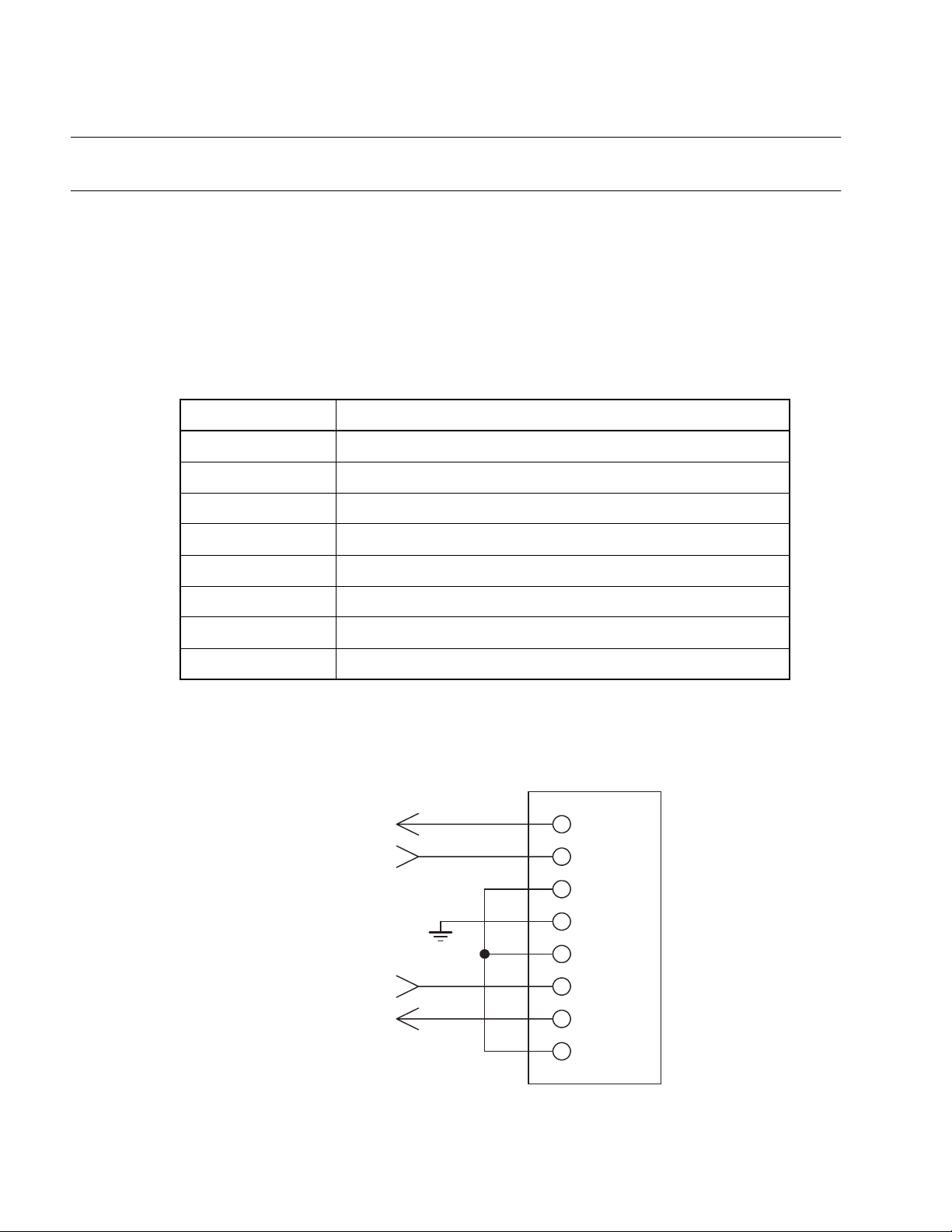
Figure 1.4-1 Pin assignment of the RS-232C connector
RS-232C connector
CTS
To internal emulator circuit
GND
8 (CTS)
7 (RTS)RTS
6 (DSR)
5 (GND)
4 (DTR)
3 (TXD)TXD
RXD
Note: The emulator uses pin assignments that do not use some
signal lines, as shown above.
6
2 (RXD)
1 (DCD)
Page 21

1.5 USB Port Specifications
The emulator includes a USB port.
■ USB port specifications
Table 1.5-1 "USB port specifications" lists the USB port specifications.
Table 1.5-1 USB port specifications
Item Description
Standard compliance USB 1.1
Communication mode Full Speed Bulk Transfer
Data transfer rate 12 Mbps
Connector shape Series B
1.5 USB Port Specifications
Power supply Self Powered
7
Page 22

CHAPTER 1 PRODUCT HANDLING AND SPECIFICATIONS
1.6 LAN Port Specifications
The emulator includes a LAN port.
■ LAN port specifications
Table 1.6-1 "LAN port specifications" lists the LAN port specifications.
Table 1.6-1 LAN port specifications
Item Description
Standard compliance IEEE 802.3
Communication mode TCP/IP
Data transfer rate 10 Mbps/100 Mbps
Connector shape Series B
IP address Variable
Port address Variable
Ethernet address Global: Fixed address (registered in IEEE)
Local: Variable address
8
Page 23

1.7 External Trigger Input Terminal Specifications
1.7 External Trigger Input Terminal Specifications
The emulator has a TRIG terminal for input of external trigger signals.
■ External trigger input terminal specifications
External trigger input is a function (external trigger break function) that is used to input a break
signal from external test equipment, such as a logic analyzer connected to the emulator, to the
evaluation MCU on the emulator.
Table 1.7-1 "External trigger input terminal specifications" lists the external trigger input terminal
specifications, and Figure 1.7-1 "Configuration of the peripheral circuit for the external trigger
input terminal" shows the corresponding peripheral circuit configuration.
Table 1.7-1 External trigger input terminal specifications
Terminal name Input or output Description
TRIG Input Used to input external trigger signals.
This terminal is used for break function control.
The active signal triggered by a transition from level L
to H or that by a transition from level H to L can be
selected.
A break occurs at detection of the selected active
signal that is input.
Figure 1.7-1 Configuration of the peripheral circuit for the external trigger input terminal
To internal emulator circuit
■ Precautions on use
Before using the external trigger function, read the following explanation on break slip so that
you understand its characteristics.
❍ Break slip
A trigger signal input via the external trigger input terminal is encoded in the emulator internal
circuit into the emulator interface command code. The signal is then transmitted to the
evaluation MCU in the emulator system. The emulator interface has lower clock frequency than
that the evaluation MCU (the ratio of these clock frequencies depends on the evaluation MCU
used). Therefore, a relatively large break slip (in a range of dozens to hundreds of machine
clock pulses) occurs between trigger signal input and the associated break operation of the
evaluation MCU.
74LVC244
=3.3V)
(V
cc
TRIG terminal
BNC connector
100 KΩ
GND GNDGND
9
Page 24

CHAPTER 1 PRODUCT HANDLING AND SPECIFICATIONS
1.8 Program Execution Output Terminal Specifications
The emulator has an EMUL terminal that outputs program execution signals.
■ Program execution output terminal specifications
A program execution signal is output continuously while a user program is being executed.
Table 1.8-1 "Program execution output terminal specifications" lists the program execution
output terminal specifications, and Figure 1.8-1 "Configuration of the peripheral circuit for the
program execution output terminal" shows the corresponding peripheral circuit configuration.
Table 1.8-1 Program execution output terminal specifications
Terminal name Input or output Description
EMUL Output Outputs user program execution signals.
An Level-H signal is output continuously while a user
program is being executed.
Figure 1.8-1 Configuration of the peripheral circuit for the program execution output terminal
74LVC244
(V
=3.3V)
cc
From internal emulator circuit
33 Ω
EMUL terminal
BNC connector
GNDGND
10
Page 25

1.9 Power-On Debug Specifications
1.9 Power-On Debug Specifications
The emulator has a power-on debug function that executes a program immediately
after power is turned on to the evaluation MCU.
■ Power-on debug specifications
The power-on debug function
after the power-on sequence by using the PLEV pin
This function must be preset before it can be used.
For details about presetting the function, see the Softune Workbench Operation Manual.
*1: The power-on debug function is enabled if supported by the evaluation MCU.
Before using the function, consult the Fujitsu Sales Dept. or Support Dept.
Sales Department or the Support Department of Fujitsu Limited.
*2: The PLEV pin name may depend on the evaluation MCU used.
Before using the function, consult the Fujitsu Sales Dept. or Support Dept.
(*1)
verifies the processing of an executed program immediately
(*2)
of the evaluation MCU.
■ Operational flow
Figure 1.9-1 "Flow of the power-on debug operation" shows the flow of the power-on debug
operation.
Figure 1.9-1 Flow of the power-on debug operation
· Enabling of power-on debug
· Setting of the power-off detection level
Execution of a program
User system powered off
(detection of power-off)
UVCC LED is off
No
No
User system powered on?
UVCC LED goes onYes
Operation stabilizing
time elapsed?
Yes
Execution of a program.
11
Page 26

CHAPTER 1 PRODUCT HANDLING AND SPECIFICATIONS
■ Operation outline
Figure 1.9-2 "Timing chart of the power-on debug operation" is a timing chart of the power-on
debug operation.
❍ Operation timing
Detection of power-off:
Power-off status of user system power supply voltage (UV
) is detected.
CC
When the user power supply voltage becomes equal to or less than the power-off detection
level, the emulator outputs an L-level signal to the PLEV pin of the evaluation MCU to stop
the MCU and prevent its malfunction.
(See (1) in Figure 1.9-2 "Timing chart of the power-on debug operation".)
Detection of power-on:
The power-on status of user system power supply voltage (UV
) is detected.
CC
Power-on of the user power supply (UVcc) is detected.
The function checks that a voltage higher than the power-off detection level is held for the
operation stabilization time (about 2 ms) of the evaluation MCU after the voltage is detected
as being higher than the power-off detection level.
(See (2) in Figure 1.9-2 "Timing chart of the power-on debug operation".)
After the operation stabilization time, the emulator outputs an H-level signal to the PLEV pin
of the evaluation MCU and releases the user reset input for program execution.
(See (3) in Figure 1.9-2 "Timing chart of the power-on debug operation".)
Figure 1.9-2 Timing chart of the power-on debug operation
(1)
(2)
UV
Power-off detection level
PLEV
Notes:
Setting of the power-off detection level must take the characteristics of the user power
supply (UV
If using the power-on debug function, generally set the voltage about 5% above the minimum
operation assurance voltage of the evaluation MCU. If not using the power-on debug
function, set the voltage to the minimum operation assurance voltage of the evaluation MCU.
While the PLEV pin level is low, the emulator functions (trace, event, and other) are disabled
because the evaluation MCU blocks the emulator connection to prevent the emulator from
malfunctioning.
CC
(3)
Operation stabilization
time (2 ms)
) into consideration.
CC
12
Page 27

1.10 Options
1.10 Options
A variety of options are available for the emulator. Purchase options separately as
necessary.
■ Options
The emulator unit cannot be used independently. Table 1.10-1 "Options" lists options for the
emulator. As required, purchase options to build an emulator system suitable for the evaluation
MCU used.
Table 1.10-1 Options
Name Model name
(*4)
(*4)
(*6)
(*3)
(*1)
(*2)
(*3)
(*4)(*5)
MB90Vxxx
MB2147-xx
MB2132-xxx
MB2147-xxx
-
-
-
-
Evaluation MCU
Adapter board
Probe cable
Probe header\
RS-232C cable
USB cable
LAN cable
BNC cable
*1: The model name depends on the evaluation MCU used. For more information, contact the
Fujitsu Sales Dept. or Support Dept.
*2: The adapter board is an interface board that connects the user system to the emulator
unit.
Purchase an adapter board that is compatible with the evaluation MCU used. Contact the
Fujitsu Sales Dept. or Support Dept. for information on selecting a suitable adapter board.
For information on how to handle and use an adapter board, and for related safety
precautions, see the Adapter Board Hardware Manual.
*3: The probe cable is an FPC cable that connects the user system to the emulator.
The probe header is a board that uses a flat cable to connect the user system to the
emulator.
Purchase a probe cable and header that are compatible with package of the regularproduction MCU being used. Contact the Fujitsu Sales Dept. or Support Dept. for
information on how to select a suitable probe cable and probe header.
For information on how to handle and use a probe cable and probe header, and for
related safety precautions, see the respective operation manuals.
*4: Use an RS-232C, USB, or LAN cable for the communication interface. Prepare a cable
that is compatible with both the emulator and the host machine used.
*5: Prepare an RS-232C cable by selecting a cross (interlink) type cable.
Figure 1.10-1 "Interlink cable wiring" shows interlink cable wiring.
*6: A BNC cable is required only if the TRIG or EMUL terminal in the emulator is used.
In a BNC cable is required, prepare one with an impedance of 50 ohms and a maximum
length of 2 meters.
Prepare a BNC cable that is compatible with both the emulator and the device connected
to the emulator.
13
Page 28

CHAPTER 1 PRODUCT HANDLING AND SPECIFICATIONS
Figure 1.10-1 Interlink cable wiring
Personal computer side
D-sub 9-pin
female connector
(DCD) 1
(RXD) 2
(TXD) 3
(DTR) 4
(GND) 5
(DSR) 6
(RTS) 7
(CTS) 8
(RI) 9
SHELL SHELL
Emulator side
D-sub 9-pin
female connector
1 (DCD)
2 (RXD)
3 (TXD)
4 (DTR)
5 (GND)
6 (DSR)
7 (RTS)
8 (CTS)
9 (RI)
14
Page 29

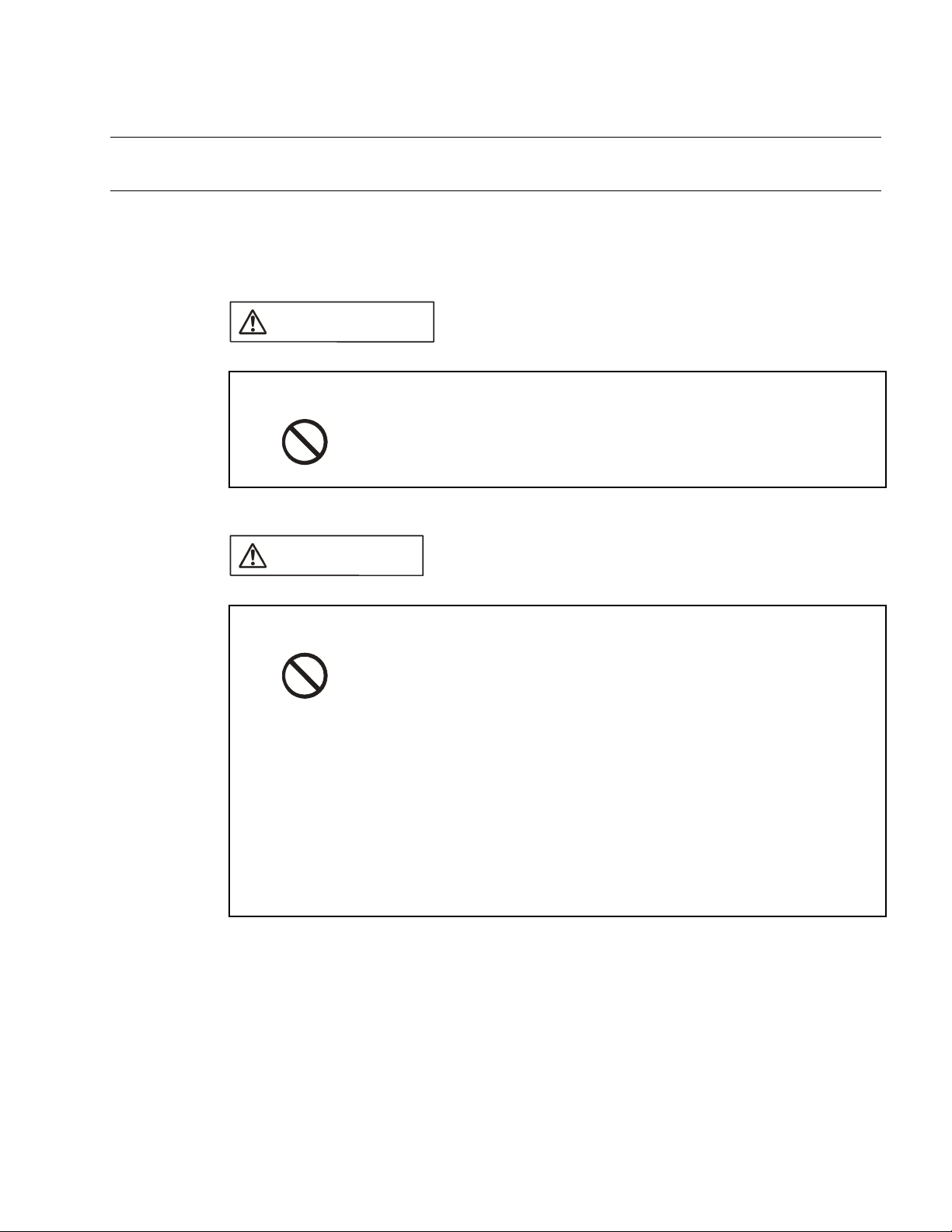
1.11 Precautions about Possible Problems
1.11 Precautions about Possible Problems
If a problem occurs during use of the emulator, take action as described below.
■ Precautions about possible problems
WARNING
Plug
If the product emits excessive heat, smoke, an offensive smell, or an
unusual noise, turn off power immediately. Then, disconnect the power
plug from the outlet. If smoke was detected, make sure that no more
smoke is coming from the product. Then, contact our sales or support
department to request that the product be repaired. Do not attempt to
repair the product by yourself. Otherwise, personal injury, damage to
the product, or other property damage may result. Using such a
product without having it properly repaired may result in fire or electric
shock.
If water or other liquid, a metallic object, or other foreign matter enters
the product, immediately turn off power, and disconnect the power plug
from the outlet. Then, consult with our sales or support department.
Using the product under such abnormal conditions may result in device
problems, fire, or electric shock.
15
Page 30

CHAPTER 1 PRODUCT HANDLING AND SPECIFICATIONS
1.12 Precautions on Handling the Product
Follow the precautions described below when handling the emulator.
■ Precautions on handling the product
WARNING
Electric shock
Plug
No disassembly
No moisture
Do not touch the inside of a connector port. Doing so may result in
electric shock or device problems.
Disconnect the power plug during electrical storms. Using the product
during an electrical storm may result in damage to the product or fire.
Do not open the product case. Do not modify the product without
permission. Doing so may result in device problems, fire, or electric
shock.
Do not use the product near water such as near a bath or shower.
Doing so may result in device problems, fire, or electric shock.
16
Page 31

WARNING
1.12 Precautions on Handling the Product
Prohibition
Do not touch the product with wet hands. Doing so may result in
electric shock.
Do not place the product in a location exposed to excessive moisture
or dust or in a poorly ventilated location. Do not place the product near
an open flame. Doing so may result in device problems, fire, or electric
shock.
Do not block the product ventilation holes. Doing so may cause
generation of excessive heat, possibly resulting in a fire.
Do not insert metallic, combustible, or other objects or allow them to
drop into the product through a ventilation hole or other opening. Doing
so may result in device problems, fire, or electric shock.
Do not use a voltage other than the indicated value of supply voltage.
Do not connect power cable together with too many plugs to an outlet.
Doing so may result in fire or electric shock.
The product must not be scratched, modified, forcibly bent, pulled,
twisted, or exposed to heat. Do not place heavy objects on the
product. Doing so may result in device problems, fire, or electric shock.
17
Page 32

CHAPTER 1 PRODUCT HANDLING AND SPECIFICATIONS
CAUTION
Plug
Prohibition
Attention
Disconnect the power plug before moving the product. Disconnect all
other connected cables. Exercise caution when working near cables
on the floor. Damage to a cable may result in fire or electric shock. A
falling device may result in injury.
If the product is not to be used for an extended period, disconnect the
power plug. Doing so may result in fire or electric shock.
Do not place the product in a location exposed to shock or a location
that is not level or stable. Doing so may result in device problems or
the product falling over or falling on the floor.
Do not grasp the cable when unplugging the power plug and cable.
Always grasp the power plug or connector itself. Pulling the cable may
expose conductors or sever wires in it, possibly resulting in device
problems, fire, or electric shock.
Do not place the product in a location, such as near a speaker or
television tuner, where it is exposed to an electromagnetic field. Doing
so may result in device problems.
Insert the power plug so that the connection is secure. Doing so may
result in device problems or fire.
18
Page 33
1.13 Precautions on Use
Follow the precautions described below when using the emulator.
■ Precautions on use
WARNING
1.13 Precautions on Use
Prohibition
CAUTION
Prohibition
Do not use the product if it has a fault, damage, or sever wires in the
cable. Doing so may result in fire or electric shock.
Do not block the product ventilation holes. Doing so may cause
generation of excessive heat, possibly resulting in a fire.
Make sure that power to the product is turned off and the power plug is
disconnected from outlets before connecting or disconnecting cables,
removing or mounting boards, handling switches or jumpers, or
mounting parts (unless such an operation uses USB cables for plugand-play devices). Doing so may result in device problems or electric
shock.
Do not grasp the cable when unplugging the power plug and cable.
Always grasp the power plug or connector itself. Pulling the cable may
expose conductors or sever wires in it, possibly resulting in device
problems, fire, or electric shock.
To prevent device damage by electrostatic discharge, do not touch,
and do not let any object contact pins of connectors or other parts of
the product. Before handling the product, be sure to discharge static
electricity from your body by touching a metallic object, such as
doorknob. Doing so may result in device problems.
Note:
Follow the instructions in this manual to set up and use the emulator.
19
Page 34

CHAPTER 1 PRODUCT HANDLING AND SPECIFICATIONS
■ Precautions on storage
CAUTION
Prohibition
Table 1.13-1 "Standard temperatures and relative humidity levels of emulator operation and
storage" lists the standard temperatures and relative humidity levels of emulator operation and
storage.
Table 1.13-1 Standard temperatures and relative humidity levels of emulator operation
and storage
Operation +5 to +35 degrees Celsius 30 to 80% (without condensation)
Storage 0 to +70 degrees Celsius 20 to 90% (without condensation)
Do not apply any shock to this product. Doing so may result in device
problems.
Do not expose the product to direct sunlight, and do not place it where
it is hot and humid. Do not allow condensation to form on the product.
Do not store the product in a dusty location. Doing so may result in
device problems.
Do not store the product where it is exposed for a long time to
relatively strong electric or magnetic fields. Because the product uses
many electronic components, problems may result.
Temperature Relative humidity
20
Page 35

CHAPTER 2 CONNECTING THE EMULATOR
This chapter explains how to connect the emulator. Read this chapter before turning
on the emulator.
2.1 "System Configuration"
2.2 "Connecting an Adapter Board"
2.3 "Connecting the User System"
2.4 "Connecting a Probe"
2.5 "Connecting a Host Machine"
2.6 "Connecting Test Equipment"
2.7 "Connecting the AC Adapter"
21
Page 36

CHAPTER 2 CONNECTING THE EMULATOR
2.1 System Configuration
The emulator is designed to be connected to and controlled by a host machine. The
host machine uses emulator debugger software to control the emulator. See the
Softune Workbench Operation Manual for information on how to use the software.
■ System configuration
Figure 2.1-1 "System configuration" shows the emulator system configuration.
Figure 2.1-1 System configuration
Emulator system
Emulator
(3)
Host machine User system
Emulator unit
(1) (2)
(4)
Test equipment
(e.g., logic analyzer)
(1) Adapter board
(*1)
(2) Probe
Probe cable
(*1)
(3) RS-232C cable
(4) BNC cable
(*1)
, flat cable, or flat cable + probe header
(*1)
, USB cable
(*1)
, or LAN cable
(*1)
(*1)
*1: To be prepared separately
22
Page 37

2.2 Connecting an Adapter Board
2.2 Connecting an Adapter Board
Insert an adapter board (option) into the adapter board connector at the top of the
emulator unit, as shown in Figure 2.2-1 "Connecting the adapter board".
■ Connecting an adapter board
CAUTION
Prohibition
Adapter board
Make sure that power to the product is turned off and the power plug is
disconnected from outlet before removing or mounting boards. Doing
so may result in device problems or electric shock.
When mounting a board, make sure that it is mounted in the proper
direction. Doing so may result in device problems.
Do not apply pressure on one part of a board when mounting the
board. Attempt to distribute equal pressure on the entire board. Doing
so may result in damage to the board.
Figure 2.2-1 Connecting the adapter board
Emulator unit
POWER
UVCC
F MC-16 SERIES EMULATOR
2
MB2147-01
23
Page 38

CHAPTER 2 CONNECTING THE EMULATOR
2.3 Connecting the User System
Connect a probe to the user system.
■ Connecting the user system
Connect a probe to the user system.
The method of connecting a probe to the user system depends on the probe configuration.
Table 2.3-1 "Probe configurations" summarizes the applicable probe configurations.
Table 2.3-1 Probe configurations
Cable used Probe configuration Connection to user system
Probe cable Probe cable Insert the connector
Flat cable Flat cable and probe
header
(*1)
of the probe cable header
into the appropriate connector
system.
Insert the connector
appropriate connector
(*1)
of the probe header into the
(*1)
of the user system.
(*1)
of the user
Flat cable Connect the connector of the flat cable to the
connector of the user system.
*1: The shape of the header connector depends on the model of header.
Example: IC socket and NQPACK connector
Note:
Before connecting the adapter board to the user system using a probe, remove the regularproduction MCU from the user system.
24
Page 39

■ Connecting (using a probe cable) to the user system
CAUTION
2.3 Connecting the User System
Prohibition
With a probe cable compatible with the package of the regular-production MCU being used,
connect the cable to the appropriate connector of the user system, as shown in Figure 2.3-1
"Connecting (using a probe cable) to the user system".
For more information on how to connect the connector of the probe cable header, see the
operation manual of the probe cable used.
Figure 2.3-1 Connecting (using a probe cable) to the user system
Make sure that power to the product is turned off and the power plug is
disconnected from outlets before connecting or disconnecting cables.
Doing so may result in device problems or electric shock.
Do not grasp the cable when unplugging the power plug and cable.
Always grasp the power plug or connector itself. Pulling the cable may
expose conductors or sever wires in it, possibly resulting in device
problems, fire, or electric shock.
Probe cable
User system
25
Page 40

CHAPTER 2 CONNECTING THE EMULATOR
■ Connecting (using flat cables and a probe header) to the user system
CAUTION
Prohibition
disconnected from outlets before connecting or disconnecting cables.
Doing so may result in device problems or electric shock.
Do not grasp the cable when unplugging the power plug and cable.
Always grasp the power plug or connector itself. Pulling the cable may
expose conductors or sever wires in it, possibly resulting in device
problems, fire, or electric shock.
With a probe header compatible with the package of the regular-production MCU being used,
connect the probe header to the appropriate connector of the user system, as shown in Figure
2.3-2 "Connecting (using flat cables and a probe header) to the user system".
For more information on how to connect the connector of the probe header, see the operation
manual of the probe header used.
Figure 2.3-2 Connecting (using flat cables and a probe header) to the user system
Make sure that power to the product is turned off and the power plug is
Flat cables
PROBE CN B2PROBE CN1 B1
Probe header
Eject locks
User system
To connect a flat cable, push its connector into the connector of the probe header until the eject locks on
both sides of the flat cable connector lock.
To disconnect a flat cable, pinch the eject locks on both sides of the flat cable connector until the flat cable
unlocks, and pull out the connector.
26
Page 41

■ Connecting (using flat cables) to the user system
CAUTION
2.3 Connecting the User System
Prohibition
If connectors that are mates of probe connectors B1 and B2 of the adapter board are mounted
in the user system, the user system can be connected to the adapter board via flat cables.
For the interface specifications of probe connector B1 and B2, see the Adapter Board Hardware
Manual.
Connect flat cables to the probe connector B1 and B2 in the user system, as shown in Figure
2.3-3 "Connecting (using flat cables) to the user system".
Figure 2.3-3 Connecting (using flat cables) to the user system
Make sure that power to the product is turned off and the power plug is
disconnected from outlets before connecting or disconnecting cables.
Doing so may result in device problems or electric shock.
Do not grasp the cable when unplugging the power plug and cable.
Always grasp the power plug or connector itself. Pulling the cable may
expose conductors or sever wires in it, possibly resulting in device
problems, fire, or electric shock.
Flat cables Eject locks
PROBE CN B2PROBE CN B1
User system
To connect a flat cable, push its connector into probe connector B1 or B2 until the eject locks on
both sides of the flat cable connector lock.
To disconnect a flat cable, pinch the eject locks on both sides of the flat cable connector until
the flat cable unlocks, and pull out the connector.
27
Page 42

CHAPTER 2 CONNECTING THE EMULATOR
2.4 Connecting a Probe
Connect a probe to the adapter board.
■ Connecting a probe
Note:
The adapter board has two pairs of probe connectors. Do not use both pairs at the same
time. Use only one of these pairs according to the configuration of the probe used.
■ Connecting a probe (using a probe cable)
CAUTION
Prohibition
Connect a probe cable to probe connectors A1 and A2 on the adapter board, as shown in
Figure 2.4-1 "Connecting a probe (using a probe cable)".
Figure 2.4-1 Connecting a probe (using a probe cable)
PROBE CN A2PROBE CN A1
PROBE CN B2PROBE CN B1
Adapter board
Make sure that power to the product is turned off and the power plug is
disconnected from outlets before connecting or disconnecting cables.
Doing so may result in device problems or electric shock.
Do not grasp the cable when unplugging the power plug and cable.
Always grasp the power plug or connector itself. Pulling the cable may
expose conductors or sever wires in it, possibly resulting in device
problems, fire, or electric shock.
Probe cable
28
Page 43

■ Connecting a probe (using flat cables)
CAUTION
2.4 Connecting a Probe
Prohibition
Connect flat cables to probe connectors B1 and B2 on the adapter board, as shown in Figure
2.4-2 "Connecting a probe (using flat cables)".
Figure 2.4-2 Connecting a probe (using flat cables)
Adapter board
PROBE CN A2PROBE CN A1
PROBE CN B2PROBE CN B1
Make sure that power to the product is turned off and the power plug is
disconnected from outlets before connecting or disconnecting cables.
Doing so may result in device problems or electric shock.
Do not grasp the cable when unplugging the power plug and cable.
Always grasp the power plug or connector itself. Pulling the cable may
expose conductors or sever wires in it, possibly resulting in device
problems, fire, or electric shock.
Flat cables
Eject locks
To connect a flat cable, push its connector into probe connector B1 or B2 until the eject locks
on both sides of the flat cable connector lock.
To disconnect a flat cable, pinch the eject locks on both sides of the flat cable connector until
the flat cable unlocks, and pull out the connector.
29
Page 44

CHAPTER 2 CONNECTING THE EMULATOR
2.5 Connecting a Host Machine
Connect a host machine to the emulator by using an RS-232C, USB, or LAN cable, as
shown in Figure 2.5-1 "Connecting a host machine".
For a Plug & Play connection with a USB cable to a host machine, power on all
relevant equipment, and then insert the USB cable plug for the host machine into the
appropriate host machine socket.
■ Connecting a host machine
CAUTION
Prohibition
Make sure that power to the product is turned off and the power plug is
disconnected from outlets before connecting or disconnecting cables
(unless such an operation uses USB cables for plug-and-play devices).
Doing so may result in device problems or electric shock.
Do not grasp the cable when unplugging the power plug and cable.
Always grasp the power plug or connector itself. Pulling the cable may
expose conductors or sever wires in it, possibly resulting in device
problems, fire, or electric shock.
Figure 2.5-1 Connecting a host machine
30
USB cable
RS-232C cable
LAN cable
Note:
Connect only one RS-232C, USB, or LAN cable between a host machine and the emulator.
Connecting multiple communication cables between them may result in abnormal operation.
Page 45

2.6 Connecting Test Equipment
2.6 Connecting Test Equipment
Connect test equipment to the emulator, as shown in Figure 2.6-1 "Connecting test
equipment", only if the external trigger input and program execution functions of the
emulator are to be used. If these functions are not used, do not connect the TRIG and
EMUL terminals.
■ Connecting test equipment
CAUTION
Prohibition
Make sure that power to the product is turned off and the power plug is
disconnected from outlets before connecting or disconnecting cables.
Doing so may result in device problems or electric shock.
Do not grasp the cable when unplugging the power plug and cable.
Always grasp the power plug or connector itself. Pulling the cable may
expose conductors or sever wires in it, possibly resulting in device
problems, fire, or electric shock.
Figure 2.6-1 Connecting test equipment
BNC cable
31
Page 46
CHAPTER 2 CONNECTING THE EMULATOR
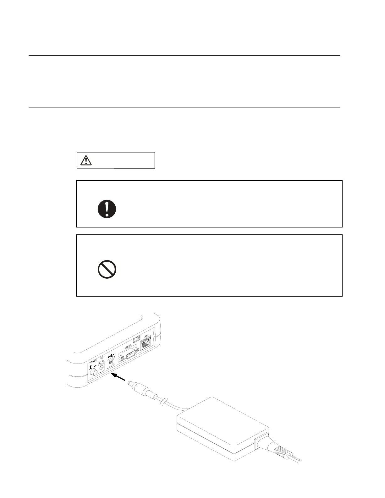
2.7 Connecting the AC Adapter
Connect the AC adapter to the emulator, as shown in Figure 2.7-1 "Connecting the AC
adapter".
First, insert the AC cord into the AC adapter. Next, connect the AC adapter to the
emulator. Lastly, insert the AC plug into an AC outlet.
■ Connecting the AC adapter
CAUTION
Attention
Prohibition
Insert the power plug so that the connection is secure. Doing so may
result in device problems or fire.
Make sure that power to the product is turned off and the power plug is
disconnected from outlets before connecting or disconnecting cables.
Doing so may result in device problems or electric shock.
Do not grasp the cable when unplugging the power plug and cable.
Always grasp the power plug or connector itself. Pulling the cable may
expose conductors or sever wires in it, possibly resulting in device
problems, fire, or electric shock.
Figure 2.7-1 Connecting the AC adapter
32
Page 47

CHAPTER 3 OPERATING THE EMULATOR
This chapter explains basic operations of the emulator. Read this chapter before
turning on the emulator.
For details about the adapter board, see the Adapter Board Hardware Manual.
3.1 "Mounting an Evaluation MCU"
3.2 "Clock Supply"
3.3 "Emulator-dedicated Power Supply Switching"
3.4 "User Port Power Supply Switching"
3.5 "Switching the C Pin Setting"
3.6 "User Data Bus Switching"
3.7 "Using the Setting Switches"
3.8 "Power-On Sequence"
3.9 "Power-Off Sequence"
33
Page 48

CHAPTER 3 OPERATING THE EMULATOR
3.1 Mounting an Evaluation MCU
Mount an evaluation MCU on the emulator.
■ Mounting an evaluation MCU
CAUTION
Prohibition
Pull the lever of an IC socket for an evaluation MCU on the emulator, and mount the evaluation
MCU while aligning the pin No. 1 index mark ( or ) of the evaluation MCU with that ( )
of the IC socket.
After mounting the evaluation MCU, push the lever of the IC socket back to its original position.
Figure 3.1-1 Mounting an evaluation MCU
Evaluation MCU
Make sure that power to the product is turned off and the power plug is
disconnected from outlets before mounting the evaluation MCU. Doing
so may result in device problems or electric shock.
Pin No. 1 index mark
34
Evaluation MCU
IC socket for the evaluation MCU IC socket for the evaluation MCU
(Top view) (Side view)
Page 49

3.2 Clock Supply
This section explains clock supply to the evaluation MCU.
■ Clock supply
CAUTION
3.2 Clock Supply
Prohibition
The emulator supplies clock pulses to the evaluation MCU.
Figure 3.2-1 "Mounting a crystal unit" shows how to mount a crystal unit in IC sockets for a
crystal unit on the emulator. Figure 3.2-2 "Configuration of peripheral circuits for the clock
circuit" shows the configuration of peripheral circuits for the clock circuit. Figure 3.2-3 "Examples
of jumper settings for subclock selection" shows examples of jumper settings for subclock
selection. Table 3.2-1 "Settings for main clock selection" lists settings of main clock selection
switches. Table 3.2-2 "Settings for subclock selection" lists settings for subclock selection.
Make sure that power to the product is turned off and the power plug is
disconnected from outlets before mounting crystal unit or handling
switches or jumpers. Doing so may result in device problems or
electric shock.
Figure 3.2-1 Mounting a crystal unit
MAIN XTAL
35
Page 50

CHAPTER 3 OPERATING THE EMULATOR
Figure 3.2-2 Configuration of peripheral circuits for the clock circuit
FC SEL
X0
X1
PA1/X0A
PA2/X1A
Evaluation MCU
MAIN XTAL
1
2
3
4
8
7
6
5
GNDGND
390 KΩ
32.768 KHz
33 pF/50 V 10 pF/50 V
1
2
3
4
5
6
7
8
SUB XTAL
CBA
X0
X1
PA1/X0A
PA2/X1A
X0A
X1A
GND GND
Figure 3.2-3 Examples of jumper settings for subclock selection
SUB XTAL
AB
X1A
X0A
C
SUB XTAL SUB XTAL
X1A
X0A
ABC
ABC
(a) (b) (c)
X1A
X0A
36
Page 51

Table 3.2-1 Settings for main clock selection
Main clock source
Clock area OFF OFF
User system ON ON
Table 3.2-2 Settings for subclock selection
3.2 Clock Supply
FC SEL setting
12
Subclock
Pin corresponding to
Availability
Available Clock area PGA
Not
available
*1: Clock oscillation with a crystal unit mounted in the user system is not supported.
*2: In the table, PGA299 and PGA256 indicate different adapter boards, which are:
PGA299: Adapter board for the PGA-299P
PGA256: Adapter board for the PGA-256P
The correspondence between subclock signals (X0A and X1A) and pin numbers on the evaluation MCU depends on the
evaluation MCU used. Check the correspondence before making settings.
For more information on the correspondence between subclock signals and pin numbers on the evaluation MCU,
contact the Fujitsu Sales Dept. or Support Dept.
Source
(*1)
the evaluation MCU
X1A: Pin No. 267
299
X0A: Pin No. 217
X1A: Pin No. 217
X0A: Pin No. 267
PGA
X1A: Pin No. 51
256
X0A: Pin No. 176
X1A: Pin No. 176
X0A: Pin No. 51
-
FC SEL
setting
34
(*2)
OFF OFF X1A:B connected to X1A:C
(a) in Figure 3.2-3
OFF OFF X1A:B connected to X0A:B
(b) in Figure 3.2-3
OFF OFF X1A:B connected to X1A:C
(a) in Figure 3.2-3
OFF OFF X1A:B connected to X0A:B
(b) in Figure 3.2-3
ON ON X1A:A connected to X1A:B
(c) in Figure 3.2-3
SUB XTAL setting
X0A:B connected to X0A:C
(a) in Figure 3.2-3
X1A:C connected to X0A:C
(b) in Figure 3.2-3
X0A:B connected to X0A:C
(a) in Figure 3.2-3
X1A:C connected to X0A:C
(b) in Figure 3.2-3
X0A:A connected to X0A:B
(c) in Figure 3.2-3
Note:
To supply the main clock signal from the user system, add an oscillation circuit to the user
system and have the main clock supplied via a CMOS buffer.
37
Page 52

CHAPTER 3 OPERATING THE EMULATOR
3.3 Emulator-dedicated Power Supply Switching
According to whether the emulator-dedicated power supply on the evaluation MCU is
available to be used, set switching of the emulator-dedicated power supply.
■ Switching of the emulator-dedicated power supply
CAUTION
Prohibition
Using the emulator-dedicated power supply switching jumper on the emulator, set the tool
interface power supply on the evaluation MCU to operate with the user power supply (UV
or the development tool power supply (+5 V).
On an evaluation MCU that has a emulator-dedicated power supply, the development tool
power supply must supply power to the evaluation MCU as a tool interface power supply.
Set the development tool power supply (+5 V) on such an evaluation MCU. On an evaluation
MCU that does not have a emulator-dedicated power supply, set the user power supply
(UV
1).
CC
For details about an evaluation MCU with a emulator-dedicated power supply, see the
Evaluation MCU Hardware Manual of the relevant product, or contact the Fujitsu Sales Dept. or
Support Dept.
Figure 3.3-1 "Emulator-dedicated power supply switching jumper" shows the emulatordedicated power supply switching jumper. Table 3.3-1 "Settings of the emulator-dedicated
power supply switching jumper" lists the settings of the jumper.
Make sure that power to the product is turned off and the power plug is
disconnected from outlets before handling jumpers. Doing so may
result in device problems or electric shock.
CC
1)
38
Figure 3.3-1 Emulator-dedicated power supply switching jumper
VCC SEL
P0V
P1V
*1
*2
*3
CBA
TOOL VCC
*1: Emulator-dedicated power supply switching jumper
*2: Power supply switching jumper of user port 0 (For details, see
Section 3.4 "User Port Power Supply Switching.")
*3: Power supply switching jumper of user port 1 (For details, see
Section 3.4 "User Port Power Supply Switching.")
Page 53

3.3 Emulator-dedicated Power Supply Switching
Table 3.3-1 Settings of the emulator-dedicated power supply switching jumper
Emulator-dedicated power supply pin Setting of VCC SEL (S1)
Available TOOL VCC: B-C connected (+5 V)
Not available TOOL VCC: A-B connected (UV
CC
1)
39
Page 54

CHAPTER 3 OPERATING THE EMULATOR
3.4 User Port Power Supply Switching
Select a user port power supply for the evaluation MCU.
■ Switching of the user port power supply
CAUTION
Prohibition
On the emulator, use the jumper for switching the user port power supply to set the reference
voltage of the user data bus probing circuit.
The user data bus for which the reference voltage is set corresponds to user ports 0 and 1. Set
the user port reference voltage for each port power supply source.
For details on the user data bus probing circuit, see Section 3.6 "User Data Bus Switching."
UV
1: Main power supply for the evaluation MCU
CC
UVCC2: Secondary power supply for the evaluation MCU
Table 3.4-1 "Settings of the jumper for switching the user port power supply" lists settings of the
jumper for switching the user port power supply.
Table 3.4-1 Settings of the jumper for switching the user port power supply
User system
power supply
source
Jumper for selecting user port 0 power
supply (P0V)
Make sure that power to the product is turned off and the power plug is
disconnected from outlets before handling jumpers. Doing so may
result in device problems or electric shock.
VCC SEL setting
Jumper for selecting user port 1 power
(*1)
supply (P1V)
(*1)
Single source A connected to B (UVCC1 setting) A connected to B (UVCC1 setting)
Jumper connection on target power supply
(*2)
Dual source
*1: See Figure 3.3-1 "Emulator-dedicated power supply switching jumper" for positions of the jumper for
switching the user port power supply.
*2: Set a jumper connection to select the VCC that corresponds to a user port power supply.
Example: User port 0 power supply is UV
Jumper for selecting user port 0 power supply (P0V): Connect A to B (UV
Jumper for selecting user port 1 power supply (P1V): Connect B to C (UV
40
side
A connected to B
(UV
1 setting)
CC
B connected to C
(UVCC2 setting)
1, and user port 1 power supply is UVCC2:
CC
Jumper connection on target power supply
(*2)
side
A connected to B
(UVCC1 setting)
1 setting).
CC
2 setting).
CC
B connected to C
(UVCC2 setting)
Page 55

3.5 Switching the C Pin Setting
3.5 Switching the C Pin Setting
Set the setting of the C-pin selection switch according to whether the evaluation MCU
has the C-pin.
■ Switching the C-pin setting
CAUTION
Prohibition
On the emulator, use the C-pin selection switch to set the C-pin setting.
Figure 3.5-1 "Configuration of the peripheral circuit for C-pin selection switch" shows the
configuration of the peripheral circuit for the C-pin selection switch. Table 3.5-1 "Settings of the
C-pin selection switch" lists the switch settings.
Figure 3.5-1 Configuration of the peripheral circuit for C-pin selection switch
Evaluation MCU
Make sure that power to the product is turned off and the power plug is
disconnected from outlets before handling switches. Doing so may
result in device problems or electric shock.
FC SEL
1
2
3
4
5
6
7
8
P70P70/C
0.1 µF/50 V
GND
Table 3.5-1 Settings of the C-pin selection switch
FC SEL setting
C-pin
56
Available OFF ON
Not available ON OFF
41
Page 56

CHAPTER 3 OPERATING THE EMULATOR
3.6 User Data Bus Switching
Set the setting of the user data bus selection switch.
■ Switching of the user data bus
CAUTION
Prohibition
If probing target pins (P00 to P07 and P10 to P17) have special specifications, such as for highvoltage ports, the user data bus probing circuit must be set to the disconnected status.
When the external bus of the evaluation MCU is not used, the disconnected status is the
recommended setting for the user data bus probing circuit.
Using the user data bus selection switch on the emulator, set the user data bus probing circuit
to the connected or disconnected status.
Figure 3.6-1 "Configuration of the peripheral circuit for the user data bus selection switch"
shows the configuration of the peripheral circuit for the user data bus selection switch. Table
3.6-1 "Settings of user data bus selection switch" lists switch settings.
Table 3.6-1 Settings of user data bus selection switch
Probing target pin 12345678
P00 to P07
(P0 SENSE setting)
Connected ON ON ON ON ON ON ON ON
Disconnected OFF OFF OFF OFF OFF OFF OFF OFF
Make sure that power to the product is turned off and the power plug is
disconnected from outlets before handling switches. Doing so may
result in device problems or electric shock.
P10 to P17
(P1 SENSE setting)
Note:
42
Connected ON ON ON ON ON ON ON ON
Disconnected OFF OFF OFF OFF OFF OFF OFF OFF
This circuit has a function equivalent to that of a pull-up circuit with high resistance.
If all buses in the evaluation MCU and user system are in the Hi-Z state, about 3.0 V
appears on the user data bus.
Page 57

3.6 User Data Bus Switching
Figure 3.6-1 Configuration of the peripheral circuit for the user data bus selection switch
P0[7:0]
To internal
emulator
circuit
Evaluation MCU
OUT
OUT
Adapter board
P1[7:0]
Probe connector
74CBTD3384MAX901
IN+
+
-
IN+
+
-
B
74CBTD3384MAX901
B
A
xOE
A
xOE
P0 SENSE
GND
P1 SENSE
GND
To probe
74CBTD3384 DC characteristic
Input current (Iin)
MAX901 DC characteristic
Input current (Iin)
1 µA
10 µA
43
Page 58

CHAPTER 3 OPERATING THE EMULATOR
3.7 Using the Setting Switches
This section explains how to use the setting switches and the display on the status
indicator LCD.
■ Functions of the setting switches
The setting switches can be used to change the information displayed on the status indicator
LCD (called "LCD" in the rest of this manual) and change LAN parameters displayed on the
LCD.
This section explains the menu displayed on the LCD and how to use the setting switches with
by selecting from the menu. For details about use of the switches and information displayed on
the LCD in menu selection mode or normal operation mode, see the Softune Workbench
Operation Manual.
Table 3.7-1 "Functions of the setting switches" lists the functions of the setting switches.
Table 3.7-1 Functions of the setting switches
Key name Marking created by
silk screen printing
ENTER key
Up/Down key
/
Information displayed
on LCD
Initial screen for emulator Changes the screen to the menu.
Menu Changes display to the submenu of
the selected item.
LAN parameter Sets the column (position) to be
changed.
Sets a new value (numeric value).
Selection/Confirmation Sets a selected item or terminates
display after confirmation.
Menu Scrolls display upward or downward.
LAN parameter Moves the cursor upward, downward,
to the left, or to the right.
LAN parameter Increments or decrements the value
(numeric value) to be changed.
Function
44
Page 59

■ Using switches to change parameter values
The following procedure applies to using the setting switches to change parameter values:
1. Display parameters on the LCD. Use the Up or Down key to move the blinking cursor ( ) to
the column (position) of the value to be changed.
2. Click the ENTER key to set the column (position) of the value to be changed. The cursor
changes its form to "_" (underscore).
3. Use the Up or Down key to increment or decrement the defined value (numeric value) to the
desired value (numeric value).
4. Click the ENTER key to confirm the new value (numeric value) to be set.
5. Change all values (numeric values) of the parameters to be modified. After that, use the Up
or Down key to move the cursor to the location immediately to the right of "[OK]," and click
the ENTER key to end the parameter value change operation.
■ Using switches for selection or confirmation
The following procedure applies to using the setting switches for selection and confirmation:
• For selection
Use the Up or Down key to move the cursor to the location immediately to the right of an
item or command (e.g., [Yes] or [No]) to select the item or command, and click the ENTER
key.
3.7 Using the Setting Switches
• For confirmation
Move the cursor to the location immediately to the right of [OK], and click the ENTER key.
45
Page 60

CHAPTER 3 OPERATING THE EMULATOR
■ Display configuration
Figure 3.7-1 "Menu configuration" shows the menu configuration.
Figure 3.7-1 Menu configuration
Fujitsu Emulator
Loader Mode Now.
---- MENU ----
1. LAN
---- LAN ----
1. IP Address
---- LAN ----
2. Subnet Mask
---- LAN ----
3. MAC Address
---- LAN ---
4. Port Address
---- LAN ----
5. Exit
---- MENU ----
2. USB
192.168.000.001
OK
255.255.255.000
OK
xxxxxxxxxxxx
OK
05001
OK
Parameter Save?
YES NO
TOP MENU RETURN?
OK CANCEL
ffffffffffff
OK
• This is the initial screen for the emulator.
This screen appears first when the emulator is in the factory
default that is set before shipment. The information displayed
on this screen depend on the firmware registration status.
• This is the initial menu screen displayed and the LAN
information menu.
• This screen displays an IP address and enables users to
change it.
• This screen displays a subnet mask and enables users to
change it.
• This screen displays a MAC address.
The MAC address specific to the emulator is displayed.
• This screen displays a port address and enables users to
change it.
• This screen enables users to save changed LAN parameter
values.
• This screen enables users to select to end the display of the
LAN information menu.
• This screen is reserved for displaying the USB information
menu.
---- MENU ----
3. Loader Mode
---- MENU ----
4. Information
- INFORMATION -
1. Version
- Information -
2. Other
---- OTHER ----
1. KEY CLICK
---- OTHER ----
1. EXIT
- Information -
2. EXIT
---- MENU ----
5. EXIT
Loader Mode OK?
OK CANCEL
LOADER:VxxLxxRxx
CMN :VxxLxxRxx
DEPEN1:VxxLxxRxx
DEPEN2:VxxLxxRxx
DEPEN3:VxxLxxRxx
CMNSUB:VxxLxxRxx
-- KEY CLICK - ON OFF
• This screen displays the loader information menu.
Select [OK] to enable loading.
• This screen displays the information menu.
• This screen displays version information.
Use the Up and Down keys to scroll the version information on
the screen.
To return to a higher-level screen, press the ENTER key.
• This screen displays other settings and enables users to
change them.
• This screen enables users to turn on and off the clicking sound
generated when a setting switch is clicked.
• This screen is used to end the display of other settings.
• This screen is used to end the display of the information menu.
• This screen is used to end the display of the menu.
46
Page 61

3.8 Power-On Sequence
3.8 Power-On Sequence
After making all necessary connections and settings, power on the host machine,
emulator, and user system in this sequence.
For the first use of the emulator after shipment, the emulator must be initialized
(monitor loading) before the power-on sequence of the user system.
■ Power-on sequence
CAUTION
Prohibition
Figure 3.8-1 "Power-on sequence" shows the sequence of power-on operations. Perform the
power-on operations in this sequence after making all necessary connections and settings.
To turn on the emulator, push the POWER switch on the back panel of the emulator (see Figure
1.2-3 "Rear view of the emulator unit" for the location of the POWER switch). The POWER
switch is then locked in the ON position (pushed in).
For the first use of the emulator after shipment, the emulator must be initialized (monitor
loading) before the power-on sequence of the user system. For information on how to initialize
it, see the Softune Workbench Operation Manual.
Follow the procedure described in the manual to turn on the product.
Doing so may result in device problems.
After power is turned on to the product, do not move the system, or
apply any shock or vibration to it. Doing so may result in device
problems.
47
Page 62

CHAPTER 3 OPERATING THE EMULATOR
Figure 3.8-1 Power-on sequence
Turn on the host machine (if necessary).
Has the emulator been initialized?
Turn on the user system.
Turn on the emulator.
POWER LED goes on.
No
Yes
Initialize the emulator.
Press the RESET switch on the emulator.
Note:
If the emulator has been sent to a factory for repair, the emulator is
returned in the factory default (same as that at initial shipment). In this
event, initialize the emulator before using it.
48
Page 63

3.9 Power-Off Sequence
3.9 Power-Off Sequence
Power off the user system, emulator, and host machine in this sequence.
■ Power-off sequence
CAUTION
Prohibition
Figure 3.9-1 "Power-off sequence" shows the sequence of power-off operations. Perform the
power-off operations in this sequence.
To turn off the emulator power, push the POWER switch on the back panel of the emulator (see
Figure 1.2-3 "Rear view of the emulator unit" for the location of the POWER switch). The
POWER switch then returns to the OFF position (protruding).
Follow the procedure described in the manual to turn off the product.
Doing so may result in device problems.
Figure 3.9-1 Power-off sequence
Turn off the user system.
Turn off the emulator.
Turn off the host machine (if necessary).
49
Page 64

CHAPTER 3 OPERATING THE EMULATOR
50
Page 65

CM42-00412-1E
FUJITSU SEMICONDUCTOR • CONTROLLER MANUAL
F2MC-16L/16LX EMULATOR
MB2147-01
HARDWARE MANUAL
July 2002 the first edition
Published
Edited Technical Information Dept.
FUJITSU LIMITED
Electronic Devices
Page 66

 Loading...