

Page 1

FUJITSU SEMICONDUCTOR
SUPPORT SYSTEM
SS01-26008-1E
F2MC Series
F2MC-8FX STARTER KIT (ver. 5V)
MB2146-401-03
SETUP GUIDE
Page 2
PREFACE
Thank you for purchasing the F2MC * Series F2MC-8FX Starter Kit (ver. 5V) (Model : MB2146-40103, referred to as "Starter Kit" in this manual).
This product is a starter kit for F2MC-8FX MB95FV100-103 ( ver. 5V), which comes with MB2 146-
2
MC Series BGM Adapter, referred to as "BGM Adapter"), MB2146-303 (F2MC-8FX Family
09 (F
MCU Board for MB95FV100-103 , referred to as "MCU Boar d"), MB2146-401 (F
Evaluatio n Board, r eferred to as "Evaluation Board"), and F
sional Pack.
This manual explains how to use the St arter Kit. Be sure to read this man ual before using the product.
For mass production/evaluation MCUs for this product, consult our Sales or Support representatives.
* : F2MC is the abbreviation used for FUJITSU Flexible Microcontroller.
■ Handling and use
Handling and use of this product and notes regarding its safe use are described in the manuals for
products bundled with the Starter Kit.
Follow the instructions in the manuals to use this product.
Keep this manual at hand so that you can refer to it anytime during use of this product.
■ Caution of the products described in this document
The following precautions apply to the product described in this manual.
2
2
MC-8L/8FX Family SOFTUNE Profes-
MC-8FX Family
WARNING
Electric shock,
Damage
Electric shock,
Damage
Indicates a potentially hazardous situation which, if not avoided appropriately,
could result in death or serious injury and/or a fault in the user’s system.
Before performing any operation described in this manual, turn off all the power
supplies to the system. Performing such an operation with the power on may
cause an electric shock or device fault.
Once the product has been turned on, do not touch any metal part of it.
Doing so may cause an electric shock or device fault.
Page 3
CAUTION
Cuts, Damage
Cuts
Indicates a potentially hazardous situation which, if not avoided appropriately, may
result in minor or moderate injury and/or damage to the product or the equipment
to which the product is connected, to software resources such as data, or to other
properties.
Before moving the product, be sure to turn off all the power supplies and unplug the
cables. Watch your steps when carrying the product. Do not use the product at an
unstable location such as a place exposed to strong vibration or a sloping surface.
Doing so may let the product fall, resulting in an injury or fault.
The product has some sharp-pointed or edged parts inevitably exposed, such as
jumper plugs. Use meticulous care in handling the product not to get injured with
such pointed parts.
Damage
Damage
Damage
Damage
Damage
Damage
Neither put anything on or apply shock to the product. Once the product has been
powered, do not carry it. Doing either may cause a fault due to a load or shock.
Since the product contains many electronic components, keep it away from direct
sunlight, high temperature, and high humidity to prevent condensation. Do not use
or store the product where it is exposed to much dust or a strong magnetic or elec
tric field for an extended period of time.
An adverse operating or storage environment can cause a fault.
Use the product within the ranges of its general specifications.
Please see the item of "Specification" that has been described to the manual of
each product for the range of the specification.
Operating it outside the range of any general specification may cause a fault.
To prevent electrostatic breakdown, do not let your finger or an object touch any
metal part of the connector. Before handling the product, touch a metal object (such
as a door knob) to discharge static electricity from your body.
When turning the power on or off, follow the relevant procedure described in this
document. Before turning the power on, in particular, be sure to finish making all the
required connections. To set up and use the product, follow the instructions given
in this document.
Using the product incorrectly or inappropriately may cause a fault.
Before plugging or unplugging any cable for this product, be sure to turn the power
supply off. When unplugging the cable, remove it while holding the connector with
out pulling the cable itself. Pulling the cable itself or bending it may expose or disconnect the cable core, resulting in a fault.
-
-
Damage
Damage
Although the MCU socket is structured not to accept an evaluation MCU in a wrong
orientation or position, pay due attention to the mounting orientation when mounting
the evaluation MCU. Forcing the evaluation MCU to be inserted in a wrong orienta
tion can damage the pins of the evaluation MCU and the accidental insertion prevention mechanism of the socket, resulting in a fault.
When stored, the product should be kept in its packaging box as it has no housing.
Re-transporting the product may damage it to cause a fault. Keep the packaging
materials used for shipment of the product and use them when re-transporting it.
-
Page 4

• The contents of this document are subject to change without notice.
Customers are advised to consult with FUJITSU sales representatives before ordering.
• The information, such as descri ptions of function an d application circuit examples, in this document are presented solely for the purpose of reference to show examples of op erations an d uses of FUJITS U semi conducto r devi ce; FUJITSU
does not warrant proper operation of the device with respect to use based on such information. When you develop
equipment incorporating the device based on such information, you must assume any responsibility arising out of such
use of the information. FUJITSU assumes no liab ility for any damages whatsoever arising out of the use of the information.
• Any information in this document, including descriptions of function and schematic diagrams, shall not be construed
as license of the use or exercise of any intellectual property right, such a s pa ten t ri ght or c op yri gh t , or any o the r ri gh t
of FUJITSU or any third party or does FUJITSU warrant non-infringement of any third-party’s intellectual property
right or other right by using such information. FUJITS U assumes no liabil ity for any infringeme nt of the intellectual
property rights or other rights of third parties which would result from the use of information contained herein.
• The products described in this document are designed, developed and manufactured as contemplated for general use,
including without limitation, ordinary industr ial use, genera l office use, personal u se, and household use, b ut are not
designed, developed and manufactured as contemplated (1) for use accompanying fatal risks or dangers that, unless
extremely high safety is secured, could have a serious effect to the public, and could lead directly to death, personal
injury, severe physical damag e or other loss (i.e., nu clear reac tion control in nuclear facility, aircraft flight control, air
traffic control, mass transport control, medical life support system, missile launch control in weapon system), or (2)
for use requiring extremely high reliability (i.e., submersible repeater and artificial satellite).
Please note that FUJITSU will not be liable against you and/or any third party for any claims or damages arising in
connection with above-mentioned uses of the products.
• Any semiconductor devices have an inherent chance of failure. You must protect agains t injury, da mage or loss from
such failures by incorporating safety design measures into y our facility and equ ipment such as redundan cy, fire protection, and prevention of over-current levels and other abnormal operating conditions.
• If any products described in th is document represen t goods or techno logies subjec t to certain restricti ons on export under the Foreign Exchange and Foreign Trade Law of Japan, the prior authorization by Japanese government will be
required for e x por t of th os e pro du c ts fr om J a pan .
©2005 FUJITSU LIMITED Printed in Japan
Page 5

www
Contents
1. Checking the Delivered Product ........................................................................1
2. Handling Precautions........................................................................................ 1
3. Feature... .. .............. .. ............. .. .............. .. ............. .. .............. .. ............. .. ............ 2
4. Hardware Setu p ............. ............. .. ............. .. .............. .. ............. .. .............. .. ......2
4.1 Configuration of each product............................................................................................... 3
4.2 Connection of each product ...................................................................................................5
5. Software Setup.................................................................................................. 9
5.1 Installation of software.......................................................................................................... 9
5.2 Operation of S
OFTUNE
...........................................................................................................13
iii
Page 6
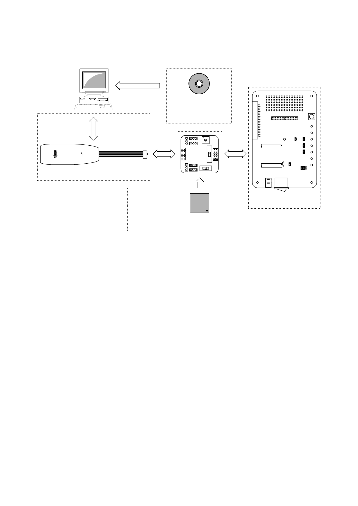
1. Checking the Delivered Product
Host machine This version is limited to 45 days
Before using the product, make sure that the following components are included:
MB2146-09
F2MC-8L/8FX Family
Professional Pack
S
OFTUNE
Trial Version
(S
OFTUNE
USB Cable Connector
(BGM Adapter enclosure)
MB2146-09
(BGM Adapter)
MB95FV100-103
(mounting at the MCU Board back )
MB2146-303
(MCU Board)
• MB2146-09
• MB2146-303
• MB2146-401
2
MC-8L/8FX Family : 1
• F
S
OFTUNE
*1
*2
*3
Professional Pack Trial Version *
4
• Setup Guide (Japanese version) : 1
• Setup Guide (English version, this manual) : 1
The inside of a dashed line is the package
of this product.
)
MB2146-401
(Evaluation Board)
: 1
: 1
: 1
*1 : To use the BGM Adapter, connect it to the host machine and USB cable. The USB cable is
enclosed by the BGM Adapter.
*2 : MB95FV100-103 is implemented in the MCU Board.
To use the MCU Board, connect it to the BGM Adapter and the Evaluation Board.
*3 : To use the Evaluation Board, connect it to the MCU Board. AC Adapter is enclosed by the
evaluation board
*4 : To use the S
, install it in your host machine.
OFTUNE
The duration of this version is limited to 45 days.
MB2146-401-01 is used as a starter kit for F2MC-8FX MB95FV100-103 (ver. 5V) by combining
with the bundled products.
For details about this product, consult our Sales or Support representatives.
2. Handling Precautions
The Starter Kit can be used in connection with its bundled products. To ensure correct use of this
product in a proper environment, observe the following guideline:
• Follow the instructions described in each manual for the bundled product to use this product.
1
Page 7

3. Feature
The F2MC-8FX starter kit is the best for a performance and functional evaluation, and a check of
operation before including F
header board, continuation use also of the evaluation with a user's system can be carried out.
Below, the feature of the BGM debugger for F2MC-8FX is shown.
4. Hardware Setup
In the hardware setup procedure, you configure an d connect t he hardware pro ducts. Thi s chapter includes the configuring and connecting procedure for each product in order. Check the contents and
complete the hardware setup.
2
MC-8FX in a user's system.By carrying out add iti on al purchase of the
• Microcomputer operation voltage It corresponds to +2.7V to +5.5V.
(The maximum and minimum of m icrocomputer oper ation voltage and freq uency of operatio n
differs with each MCU. refer to the documents (a data sheet, hardware manual, etc.) of each
device relation for th e frequency of MCU of operation.)
• Compact development environment, a light and small BGM Adapter.
• Since a monitor program is performed in exclusive memory space, it does not consume user
memory space.
• Continuation execution, step execution, a command b reak, a data br eak, sequ ential break cor
respondence
• Command trace is possible (a maximum of 16 branches).
• It connects with a host machine by the USB interface.
-
• Configuration of each product
- Configuring MCU Board
- Configuring Evaluation Board
• Connection of each product
- Connecting MCU Board and Evaluation Board
- Connecting BGM Adapter
- Connecting oscillators
- Connecting AC Adapter
2
Page 8
4.1 Configuration of each product
This section describes how to configure the MCU Board and the Evaluation Board.
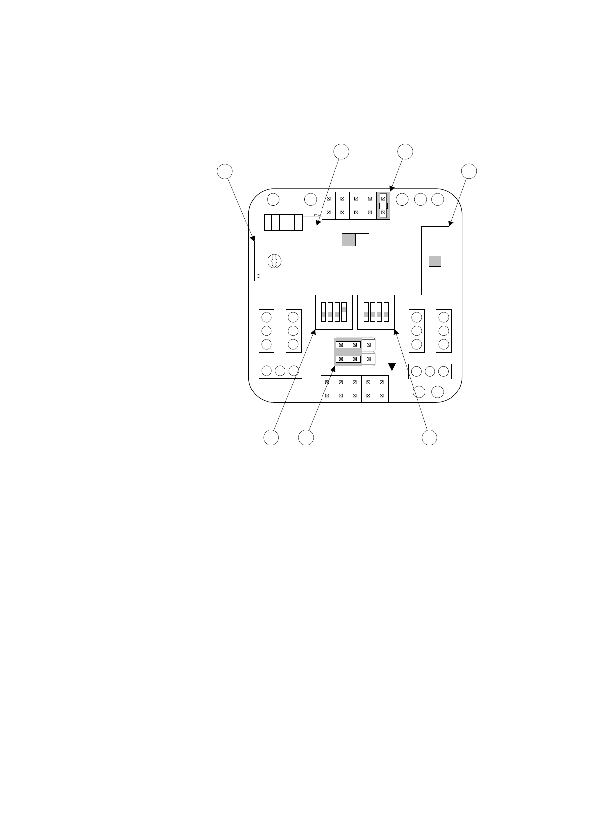
■ Configuring MCU Board
Set the following switches on the MCU Board, referring to "Figure 1 MCU Boar d Configuration".
2
3
GNDVCC
LVD1
LVD4
LVD3
LVD0
LVD2
8
9
7
A
6
B
5
C
4
D
3
E
2
F
1
0
CLK
CLK S.V.
APB8CX0X1X0A
PRODUCT SELECT
5
SUB CLOCK
BGM
ADAPTER
7
ON ON
1 2 3 4 1 2 3 4
C B A
1
4
3V5V
LVD2OFFLVD1
X1A
1
2
MAIN CLOCK
6
LVD2 detection voltage selection jumper plug
➀
Set the value to "LVD0".
Voltage selector swi tch
➁
Set the value to "5V".
Product selector switch
➂
Rotate the center tab to position the pointer for the corresponding number:
For 100-pin package, set the value to "0".
For 80-pin package, set the value to "1".
For 64-pin package, set the value to "2".
For 48-pin package, set the value to "3".
For none of the above, check on the settings in the MCU Board manual.
LVD selector switch
➃
Set the value to "OFF".
Miscellaneous switches
➄
Set "C" to "ON".
Set "CLK" to "OFF" if you use subclock, or "ON" if you don’t.
Set the other switches to "OFF" (to the side of numeral letters).
Clock input selector switch
➅
Set all to "OFF" (to the side of numeral letters)".
Subclock selector jumper plug
➆
Set all the values to the side of "B-C".
Figure 1 MCU Board Configuration
3
Page 9
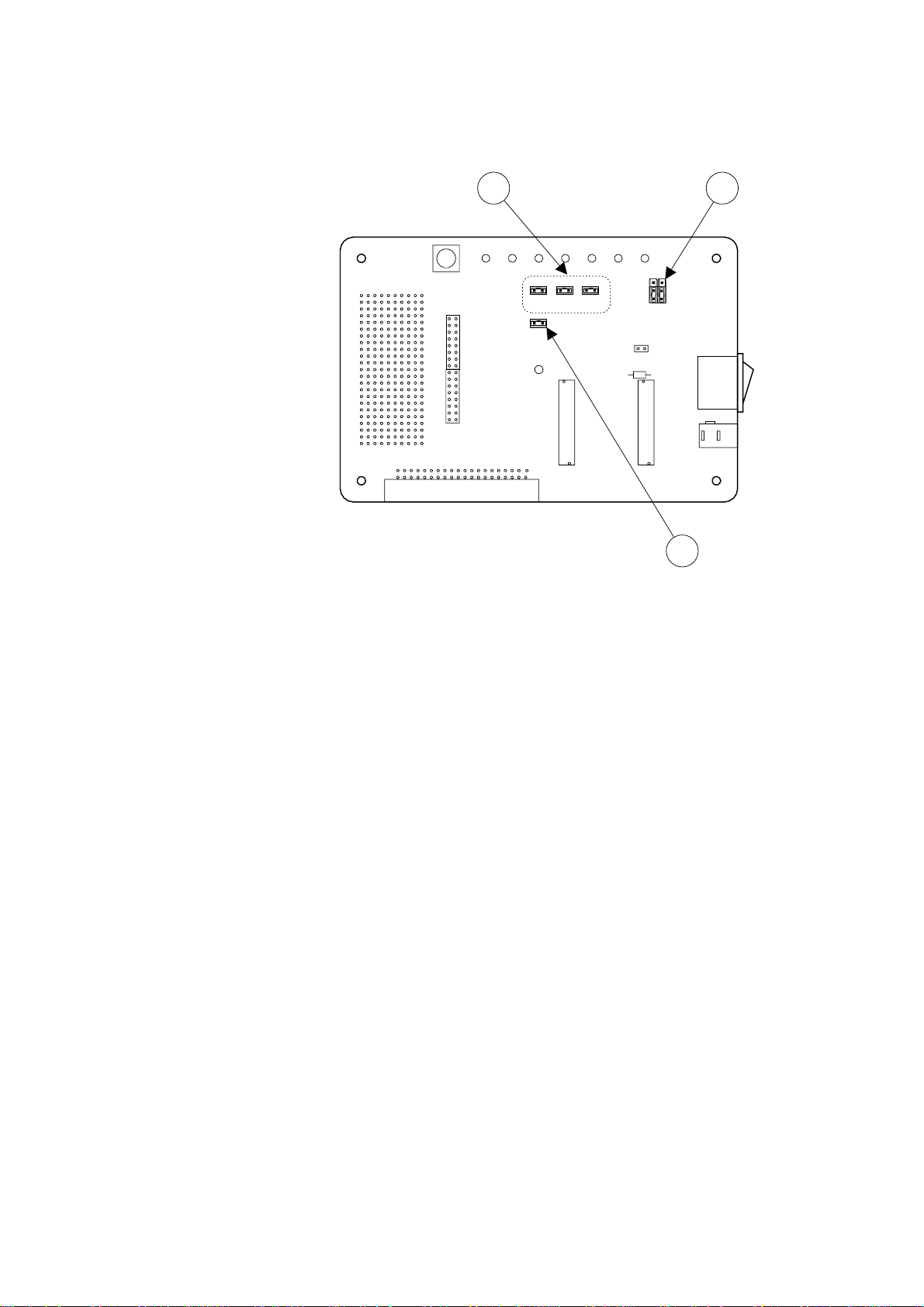
■ Configuring Evaluation Board
Set the following switches on the Evaluation Board, referring to "Figure 2 Evaluation Board Configurarion".
SW1
JP1
JP2
CN4
5V/3.3V Power supply selector jumper plug
➀
Set the value to the side of "+5V".
Analog power supply jumper plug
➁
Insert jumper plug for all the switches.
MOD selector jumper plug
➂
Insert jumper plug.
2
JP7
JP8
JP6 JP5
1
2
CN2
119
120
+3.3V
JP3 JP4
+5V
CN3
1
2
CN1
119
120
1
SW2
PJ1
3
Figure 2 Evaluation Board Configuration
4
Page 10

4.2 Connection of each product
This section describes how to co nnect the MCU Board, the Evaluation Board, and the BGM Adapter .
This section also describes how to mount the crystal oscillator on the MCU Board, and how to plug
the AC adapter into the Evaluation Board.
■ Connecting MCU Board and Evaluation Board
Connect the MCU Board and the Eva luation Board, r eferring to "Fi gure 3 Connectio n of MCU
Board and Evaluation Board". Each board has an index to avoid the reve rse m oun ting. Lo ok at the
index position to connect the boards.
Evaluation Board
SW1
JP1
Index
CN4
JP2
(Backside mounting)
120
119
120
119
CN2
CN1
2
1
2
1
MCU Board
PJ1
SW2
(Backside mounting)
Figure 3 Connection of MCU Board and Evaluation Board
CN3
JP7
JP6 JP5
JP3 JP4
+5V
Index
+3.3V
5
Page 11

■ Connecting BGM Adapter
Connect the BGM Adapter and the MCU Board, referring to "Figure 4 Connection of BGM Adapt er". The BGM Adapter and the MCU Bo ard h a ve an index mark (for pin 1) on it s connect o rs. Align
the index mark on both sides.
Plug a USB cable into the BGM Adapter (the cable is bundled with the BGM Adapter).
Make sure that POWER-SW on the Evaluation Board is set to OFF (to the side of " ") before plugging the cable.
Plug into BGM Adapter
USB cable
(Bundled with BGM Adapter)
MB2146-09
BGM Adapter
MCU Board
Index mark
Evaluation Board
JP2
CN4
PJ1
SW2
Power-SW
SW1
JP1
JP7
JP6 JP5
JP3 JP4
CN3
+3.3V
+5V
Figure 4 Connection of BGM Adapter
6
Page 12

■ Connecting oscillators
Plug crystal/ceramic oscillators into the crystal oscillator mounting sockets (one for the main clock
and the other for the subclock) on the MCU Board (See "Figure 5 Connection of oscillators") .
You can see one crystal oscillator mounting socket for main clock and the other for subc lock on the
MCU Board. Mount a crystal or ceramic oscillator and a capacitor on the MCU Board.
GND
VCC
LVD4
LVD3
LVD1
LVD0
LVD2
8
9
7
A
6
B
5
C
4
D
3
E
2
F
1
0
CLK
CLK S.V.
APB8CX0X1X0A
PRODUCT SELECT
ADAPTER
ON ON
1 2 3 4 1 2 3 4
SUB CLOCK
BGM
C B A
2
Crystal oscillator mounting socket for main clock
➀
Mount a crystal oscillator used as "main clock".
Crystal oscillator mounting socket for subclock
➁
Mount a crystal oscillator used as "subclock".
If you disable the subclock, set the "CLK" switch to "ON".
3V5V
LVD2OFFLVD1
X1A
1
2
MAIN CLOCK
1
GND
Crystal oscillator mounting socket
Figure 5 Connection of oscillators
Capacitor mounting socketCapacitor mounting socket
Ceramic
oscillator
Crystal
oscillator
7
Page 13

■ Connecting AC Adapter
Connect the AC Adapter and the Evaluation Board, referring t o "Figur e 6 Connection of AC Adapter". The AC Adapter (bundled with the Evaluation Board) is plugged into t he PJ1 on Evaluation
Board and the AC 100V Power Supply.
MB2146-09
Evaluation Board
CN4
JP2
JP1
CN3
+5V
JP7
JP6 JP5
JP3 JP4
SW1
+3.3V
BGM Adapter
Plug into Evaluation Board
Figure 6 Connection of AC Adapter
PJ1
SW2
AC Adapter
8
Page 14

5. Software Setup
In the software setup procedure, you install and operate the software applications.
This chapter includes the installing and operating procedure for each software in order. Check the
contents and complete the software setup.
• Installation of software
- Installing S
- Installing USB driver
- Installing sample program
• Operation of S
- Starting S
- Starting Debugging
- Initializing MCU
- Running the program
- Aborting the program
- Ending Debugging
- Exiting S
5.1 Installation of software
This section describes how to install S
how to install the sample program.
OFTUNE
OFTUNE
OFTUNE
OFTUNE
Workbench
Workbench
OFTUNE
and the USB driver in your host machine, as well as
■ Installing S
OFTUNE
Follow the instruction described in "F2MC-8L/8FX Family 8-bit Microcontroller S
bench Installation Guide" to install S
■ Installing USB driver
Plug a USB cable connected to BGM Adapter into your host machine. After you connect the host
machine and the BGM Adapter, the [Found New Hardware Wizard] window appears. Follow the in
struction below to install the USB driver.
In a few seconds after the above dialog is displayed, the [Welcome to the Found New Hardware Wizard] screen appears. Click [Next] to install the device driver.
OFTUNE
in your host machine.
OFTUNE
Work-
-
9
Page 15

The [Install New Hardware Device Drivers] screen appears.
Click [Search for a suitable driver for my device (recommended)], and then click [Next] to search
for a suitable driver for your device.
The [Locate Driver Files] screen appears.
Check [Specify a location], and then click [Next] to specify the location for the driver.
10
A file location dialog appears.
Select "SiUSBdB.INF" in the "\Drivers" folder (under a directory where S
click [Open] to specify the driver.
OFTUNE
is installed), and
Page 16

In the [Copy manufacturer’s files fro m] bo x, make sure t hat t he "\Dri vers" folder (und er a di rectory
where SOFTUNE
The [Driver Files Search Results] screen appears.
Click [Next] to start installing the driver.
is installed) is selected, and click [OK].
The [Completing the Found New Hardware Wizard] screen appears.
Now that the USB driver installation has completed, click [Finish] to exit the Wizard.
11
Page 17

■ Installing sample program
Copy only a folder named "\fsg" und er "\MAN UAL\Fi rs tStepGu id e" in S
ple" folder under a directory where S
All the data in the "\fsg" folder is set to "read-only". Open th e folder’s properties, and deselect the
[Read Only] checkbox, and click [OK].
OFTUNE
is installed.
OFTUNE
CD into the "\sam-
In the [Confirm Attribute Change] dialog, check [Apply Changes to this folder, sub-folders, and
files], and click [OK] to confirm the attribute change.
Note : This software application uses the relo ad ti me r, so it c an not b e us ed in 4 8- pi n pa ck age or le ss , wh ich
does not implement the reload timer. When using this software, set 64-pin package or more in the prod
uct selector switch on MCU Board.
-
12
Page 18

5.2 Operation of
This section describes how to start S
OFTUNE
S
OFTUNE
Workbench and operate it using the sample program.
■ Starting S
OFTUNE
Workbench
Start S
[Open Workspace].
OFTUNE
and configure the S
OFTUNE
development environment. From the [File] menu, click
In a file location dialog, select the "\sample\fsg\8fx_sample" folder under a directory where S
is installed, and specify "fsg_sample.wsp", then click [Open].
OFTUNE
13
Page 19

Select and right-click "e mu_dbg.su p" under the "Debug" fol der, then cli ck [Change Set tings] t o start
the setup wizard.
14
Page 20

The setup wizard is started. Click [Next].
In [Debug Type], specify [Emulator Debugger], and click [Next].
In [ICE Type], specify [MB2146-09], and click [Next].
15
Page 21

In [Device Name], specify [USB], and click [Next].
In [Output Frequency], set the frequency of oscillator connected to MCU Board, and click [Next].
The [Batch file] setting is not required. Click [Next].
16
Page 22

Check [Auto-load when starting debug], and specify "fsg_sample.prc" in [After] under [Specification batch file before/after load], then click [Next].
Check [Select All], and click [Next].
Click [Finish] to complete the setup of S
OFTUNE
development environment.
17
Page 23

■ Starting Debugging
<Turning Evaluation Board on>
Before starting debugging, turn the Evaluation Board on. Push POWER-SW on the Board to ON (to
the side of " | ") to turn it on (See "Connecting BGM Adapter" for information about POWER-SW) .
After the Evaluation Board is turned on, click [Start debug] from the [Debug] menu to start debugging.
When you start debugging, the sample program is automatically loaded.
18
Page 24

■ Initializing MCU
Initialize MCU. To do so, click the Reset button on the task bar.
Reset bu tton
19
Page 25

■ Running the program
You can run the program by clicking the "execution-related buttons" on the task bar.
You can also set a breakpoint by clicking the " " mark in the Source window.
[Execution-related buttons]
[Go]
[Step In]
[Step Over]
[Step Out]
[Run Until Cursor]
Source window
20
Breakpoint
Page 26

■ Aborting the program
After you have run the program, you can stop it by clicking the Abort button on the task bar.
Abort button
21
Page 27

■ Ending Debugging
To end debugging, click [End debug] from the [Debug] menu.
<Turning Evaluation Board off>
After you have finished debugging, turn the Evaluation Board off for safety. Push POWER-SW on
the Board to OFF (to the side of "
tion about POWER-SW.)
") to turn it off. (See "Connecting BGM Adapter" for informa-
22
Page 28

■ Exiting S
OFTUNE
Workbench
To exit S
OFTUNE
Workbench, click [Exit] from the [File] menu.
23
Page 29

SS01-26008-1E
FUJITSU SEMICONDUCTOR • SUPPORT SYSTEM
2
MC Series
F
2
F
MC-8FX STARTER KIT (ver. 5V)
MB2146-401-03
SETUP GUIDE
March 2005 the first edition
Published FUJITSU LIMITED Electronic Devices
Edited Business Promotion Dept.
Page 30

 Loading...