

Page 1

FUJITSU SEMICONDUCTOR
CONTROLLER MANUAL
HARDWARE MANUAL
CM42-00411-2E
F2MC-16L/16LX
EMULATION POD
MB2145-507
Page 2

Page 3

F2MC-16L/16LX
EMULATION POD
MB2145-507
HARDWARE MANUAL
FUJITSU LIMITED
Page 4

Page 5

PREFACE
■ Using the Emulation Pod Safely
This manual contains important information regarding the safe use of the MB2145-507
emulation pod.
Be sure to read this manual before using the MB2145-507 emulation pod and use the emulation
pod only as described in this manual.
Read "Safety Warnings" at the beginning of this manual and make a careful safety check before
using the emulation pod.
Store this manual in a convenient place so that you can refer to it at any time while you are
using the emulation pod.
■ Objectives and intended readers
The MB2145-507 emulation pod is a development support tool for developing and evaluating
application products that use Fujitsu 16-bit microcontrollers, F
devices.
This manual explains how to handle and connect the MB2145-507 emulation pod. It is intended
for engineers who use the MB2145-507 emulation pod (hereafter "emulation pod") to develop
application products that use the F
2
MC-16L/16LX/16F series devices.
2
MC-16L/16LX/16F series
■ Product Environment
The emulation pod operates properly at a temperature of 5 to 45 and a humidity of 30% to
80%. Do not use in high-temperature and high-humidity environments or in any environment
where condensation will form.
Do not put heavy objects on the emulation pod. Since the cabinet is made of plastic, it may
break.
When power is turned on, keep the emulation pod away from items that can short-circuit or fire.
Keep the emulation pod on as level a surface as possible. Do not operate the emulation pod in
a location subject to severe vibration, dust, or explosive gases.
If the emulation pod is not used in the correct environment as described above, injury to the
user and nearby persons or damage to the emulation pod or other property may result.
Packing materials used to ship the emulation pod can be reused to transport the emulation pod
in the case of a failure. If possible, keep the packing materials.
■ Trademark
2
F
MC is the abbreviation of FUJITSU Flexible Microcontroller.
Other system and product names in this manual are trademarks of respective companies or
organizations.
The symbols
TM
and ® are sometimes omitted in this manual.
i
Page 6
■ Safety Warnings
Important warnings items are given on the following pages.
Before using the emulation pod, read each warning and make a safety check.
Indicates that improper use may cause death or severe injury.
WARNING
Warning Description Page
Plug
Electric shock
If an abnormal condition such as heat, smoke, unusual odor, or unusual
noise occurs, immediately turn off the power and disconnect the power plug
from the receptacle.
When the smoke has disappeared, ask the distributor to repair the
emulation pod. Never make repairs yourself, since it is very dangerous.
Using the emulation pod in an abnormal state may cause a fire or electric
shock.
If water or other liquid, a metallic object, or other foreign substance gets
inside the emulation pod, immediately turn off the power and disconnect
the power plug from the receptacle.
Next, contact the distributor.
Using the emulation pod in an abnormal state may cause a failure, fire, or
electric shock.
If you hear thunder, disconnect the power plug from the receptacle. Using
the emulation pod during a thunderstorm can damage the emulation pod or
cause a fire.
Before connecting or disconnecting cables, turn off the power to the
emulation pod and connected devices, and disconnect the power plug from
the receptacle.
Failure to do so may cause an electric shock.
Do not put your fingers in the connector inlet.
Putting your fingers in the connector inlet can result in an electric shock or
failure.
8
8
9
9
9
No disassembly
No moisture
ii
Never open the emulation pod case. Do not modify the emulation pod
without permission.
Opening the case or modifying the emulation pod may cause a failure, fire,
or electric shock.
Do not use the emulation pod in a wet area such as a bathroom or shower
room.
Using the emulation pod in a wet area may cause a failure, fire, or electric
shock.
9
9
Page 7
Indicates that improper use may cause death or severe injury.
WARNING
Warning Description Page
Prohibition
Do not touch the emulation pod with wet hands.
Doing so may cause an electric shock.
Do not put the emulation pod in a location with a lot of moisture, dust, or
soot or in a location with poor ventilation. Do not place the emulation pod
near an open flame.
Doing so may cause a failure, fire, or electric shock.
Do not insert or drop any metallic, combustible, or other object through a
ventilation or other type of opening in the emulation pod.
Doing so may cause a failure, fire, or electric shock.
Do not use a voltage other than the indicated power voltage. Do not
connect the power cord in a daisy chain.
Doing so may cause a fire or electric shock.
Do not damage or alter any cables.
Putting a heavy object on a cable, or pulling, forcibly bending, distorting, or
heating a cable may damage the cable and cause a fire or electric shock.
10
10
10
10
10
iii
Page 8
Indicates that improper use may cause minor or moderate injury, or may
CAUTION
Warning Description Page
damage the emulation pod, connected equipment, data or other software
resources, or other property.
Plug
Prohibition
Before moving the emulation pod, disconnect the power plug from the
receptacle.
Also, disconnect all other cables.
Watch where you step during work.
Damaging a cable may cause a fire or electric shock. A falling device may
cause injury.
If the emulation pod will not used for a long time, for safety reasons,
disconnect the power plug from the receptacle.
Failure to do so may cause a fire or electric shock.
Do not put the emulation pod in a location subject to severe vibration or in a
location that is not level or stable. Doing so may cause a failure or cause
the emulation pod to fall.
Do not put the emulation pod in a location near a speaker or television
tuner or in any location subject to a magnetic or electric field. Doing so may
cause a failure.
When disconnecting the power plug or a cable, hold the power plug or
connector itself. Do not pull on the cable.
Pulling on a cable may cause the core wire to be exposed or cut, resulting
in a failure, fire, or electric shock.
To prevent damage from static electricity, do not let a finger or object
contact a connector pin.
10
10
11
11
11, 12
12
Do not block the emulation pod's ventilation openings.
Blocking ventilation openings causes heat to accumulate and may cause a
fire.
Do not subject the emulation pod to a shock.
Doing so may cause a failure.
Do not place the emulation pod in direct sunlight, in a high-temperature or
high-humidity environment, or in an environment in which condensation can
form.
Do not store the emulation pod in a dusty location.
Doing so may cause a failure.
Because the emulation pod uses many electronic parts, do not store it in a
location subject to strong electric or magnetic fields for a long period.
Doing so may cause a failure.
Before connecting or disconnecting a cable, turn off the power.
Failure to do so may cause an electric shock.
11, 12
13
13
13
13
17, 19,
20
iv
Page 9
Indicates that improper use may cause minor or moderate injury, or may
CAUTION
Warning Description Page
damage the emulation pod, connected equipment, data or other software
resources, or other property.
Prohibition
When disconnecting a cable, hold the cable by the connector case. Do not
pull on the cable.
Doing so may break a wire in the cable.
Before mounting the evaluation MCU, turn off the power.
Failure to do so may cause an electric shock.
Before operating the clock switch, turn off the power.
Failure to do so may cause an electric shock.
Before setting the jumper switch for the power supply, turn off the power.
Failure to do so may cause an electric shock.
Before setting the jumper switch for the C-pin circuit connection, turn off the
power.
Failure to do so may cause an electric shock.
When turning on the power, follow the procedure described in the manual.
Failure to do so may cause a device failure.
After the emulation pod power is turned on, do not turn off and turn on the
user system power.
Doing so cause a device failure.
When power is on, do not carry the emulation pod, or subject it to shock or
vibration.
Doing so may cause a device failure.
17, 19, 20
22
23
25
27
28
28
28
Attention
Caution
When turning off the power, follow the procedure described in the manual.
Failure to do so may cause a device failure.
Insert the power plug firmly in the receptacle.
Failure to do so may cause a failure or a fire.
The device can be damaged during transport. Store the packing materials
used to ship the emulation pod and use them if you need to transport it.
Using the emulation pod at an ambient temperature or humidity outside the
specified range may cause a device failure. Always use the emulation pod
within the specified temperature and humidity range.
29
11
2
6
v
Page 10

■ Configuration of This Manual
This manual consists of two chapters.
Read the manual completely before using the emulation pod.
CHAPTER 1 "PRODUCT HANDLING AND SPECIFICATIONS"
This chapter explains handling of the emulation pod and gives its specifications.
Before using the emulation pod, be sure to read this chapter and check that the product and
accessories are complete.
CHAPTER 2 "CONNECTING AND SETTINGS"
This chapter explains how to connect the emulation pod and to set switches and describes
the power-on and power-off sequences.
Read this chapter before turning power on.
An appendix contains the specification for the emulator interface in the user system.
■ Related Manuals
Also refer to the following manuals:
2
• F
MC-16L/16LX/16/16H/16F Emulator Debugger Manual Windows Edition
2
MC-16L/16LX/16/16H/16F Emulator Debugger Installation Guide
• F
• The contents of this document are subject to change without notice. Customers are advised to consult
with FUJITSU sales representatives before ordering.
• The information and circuit diagrams in this document are presented as examples of semiconductor
device applications, and are not intended to be incorporated in devices for actual use. Also, FUJITSU is
unable to assume responsibility for infringement of any patent rights or other rights of third parties
arising from the use of this information or circuit diagrams.
• The products described in this document are designed, developed and manufactured as contemplated
for general use, including without limitation, ordinary industrial use, general office use, personal use, and
household use, but are not designed, developed and manufactured as contemplated (1) for use
accompanying fatal risks or dangers that, unless extremely high safety is secured, could have a serious
effect to the public, and could lead directly to death, personal injury, severe physical damage or other
loss (i.e., nuclear reaction control in nuclear facility, aircraft flight control, air traffic control, mass
transport control, medical life support system, missile launch control in weapon system), or (2) for use
requiring extremely high reliability (i.e., submersible repeater and artificial satellite).
Please note that Fujitsu will not be liable against you and/or any third party for any claims or damages
arising in connection with above-mentioned uses of the products.
• Any semiconductor devices have an inherent chance of failure. You must protect against injury, damage
or loss from such failures by incorporating safety design measures into your facility and equipment such
as redundancy, fire protection, and prevention of over-current levels and other abnormal operating
conditions.
• If any products described in this document represent goods or technologies subject to certain
restrictions on export under the Foreign Exchange and Foreign Trade Law of Japan, the prior
authorization by Japanese government will be required for export of those products from Japan.
©2002 FUJITSU LIMITED Printed in Japan
vi
Page 11

CONTENTS
CHAPTER 1 PRODUCT HANDLING AND SPECIFICATIONS ......................................... 1
1.1 Checking the Components .................................................................................................................... 2
1.2 Drawings of Emulation Pod and Names of Parts ................................................................................... 3
1.3 General Specifications ........................................................................................................................... 6
1.4 Optional Products .................................................................................................................................. 7
1.5 Note on Errors ....................................................................................................................................... 8
1.6 Notes on Handling the Emulation Pod ................................................................................................... 9
1.7 Notes on Use ....................................................................................................................................... 12
CHAPTER 2 CONNECTION AND SETTINGS ................................................................. 15
2.1 System Configuration .......................................................................................................................... 16
2.2 Connecting the 2140 Main Unit ........................................................................................................... 17
2.3 Connecting the Probe Cable ................................................................................................................ 19
2.4 Connecting the External Probe ............................................................................................................ 20
2.5 Mounting the Evaluation MCU ............................................................................................................. 22
2.6 Supplying a Clock to the Evaluation MCU ........................................................................................... 23
2.7 Emulator-specific Power Supply .......................................................................................................... 25
2.8 Switching the C-pin Circuit Connection ............................................................................................... 27
2.9 Power-on Sequence ............................................................................................................................ 28
2.10 Power-off Sequence ............................................................................................................................ 29
APPENDIX ............................................................................................................................ 31
APPENDIX A Differences between the Emulation Pod and a Regular Production MCU .............................. 32
vii
Page 12

viii
Page 13

CHAPTER 1 PRODUCT HANDLING AND
SPECIFICATIONS
This chapter explains the handling of the emulation pod and gives its specifications.
Before using the emulation pod, read this chapter and check that the product and
accessories are complete.
1.1 "Checking the Components"
1.2 "Drawings of Emulation Pod and Names of Parts"
1.3 "General Specifications"
1.4 "Optional Products"
1.5 "Note on Errors"
1.6 "Notes on Handling the Emulation Pod"
1.7 "Notes on Use"
1
Page 14
CHAPTER 1 PRODUCT HANDLING AND SPECIFICATIONS
1.1 Checking the Components
Before using the emulation pod, make sure that no component is missing.
■ Checking the Components
CAUTION
Caution
Before using the emulation pod, check that the following component has been provided.
• Emulation pod main unit: 1
The device can be damaged during transport. Store the packing
materials used to ship the emulation pod and use them if you need to
transport it.
2
Page 15
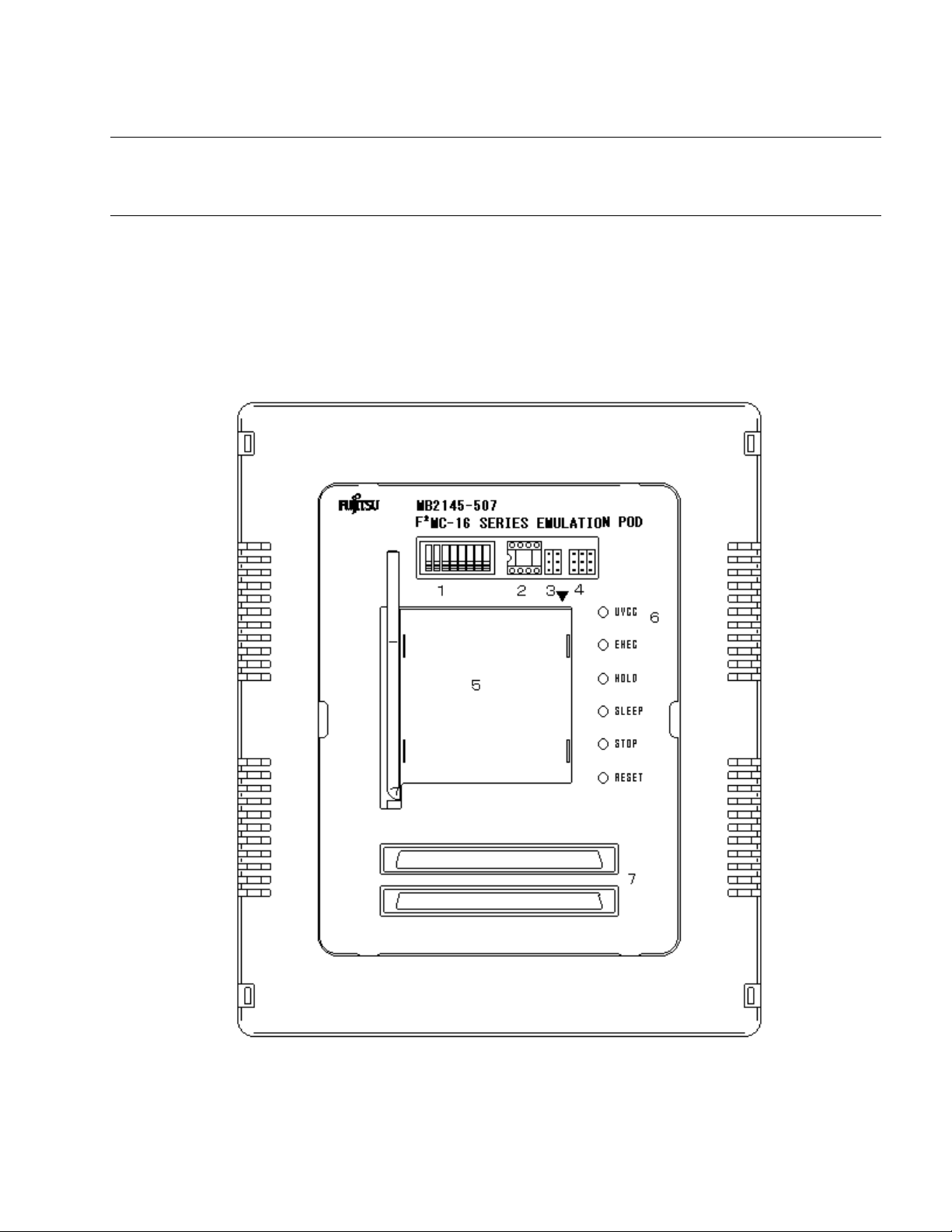
1.2 Drawings of Emulation Pod and Names of Parts
1.2 Drawings of Emulation Pod and Names of Parts
This section gives the names of the emulation pod parts. For information on
connection and settings, see Chapter 2, "Connection and Settings."
■ Views of Emulation Pod and Names of Parts
Figure 1.2-1 "Appearance of emulation pod [Front view]" to Figure 1.2-3 shows views of the
emulation and names of parts of its various parts.
Figure 1.2-1 Appearance of emulation pod (Top view)
3
Page 16

CHAPTER 1 PRODUCT HANDLING AND SPECIFICATIONS
No. Part Description
1 Switches Clock/C-pin toggle switch.
2 Crystal oscillator
mounting socket
3 Secondary clock
supply jumper
4 Power source jumper Jumper for changing the power source.
5 MCU mounting socket IC socket for mounting the evaluation MCU.
6 UVCC LED LED indicating the status of the evaluation MCU power.
EXEC LED Lights during program execution.
HOLD LED Lights in the hold state.
SLEEP LED Lights in the sleep state.
STOP LED Lights in the stop state.
RESET LED Lights in the reset state.
7 Probe connector Connector for connecting the probe cable.
IC socket for mounting the crystal oscillator.
Jumper setting for switching connections for secondary
clocks and terminals X0A and X1A.
Lights when the user system power is from 1.8 V to 5.5 V.
4
Page 17

1.2 Drawings of Emulation Pod and Names of Parts
Figure 1.2-2 Appearance of emulation pod (Front view)
No. Name Description
1 Expansion connector Connector for connecting an accessory.
2 External probe connector Connector for connecting the external probe.
Figure 1.2-3 Appearance of emulation pod (Rear view)
No. Name Description
1 Main unit interface cable
connector
Connector for connecting the main unit interface
cable.
5
Page 18

CHAPTER 1 PRODUCT HANDLING AND SPECIFICATIONS
1.3 General Specifications
Table 1.3-1 "General specifications" lists the general specifications of the emulation
pod.
■ General Specifications of the Emulation Pod
CAUTION
Caution
Table 1.3-1 General specifications
Item Specification
Name F
Model MB2145-507
Power Emulator power Voltage: +5V 5%
Operating frequency 8 KHz to 20 MHz
Operating temperature 5 to 35
Operating humidity 30% to 80% (no condensation)
Using the emulation pod at an ambient temperature or humidity
outside the specified range may cause a device failure. Always use the
emulation pod within the specified temperature and humidity range.
2
MC-16L/16LX/16F emulation pod
User system
power
Voltage: +1.8 V to 5.5 V
Current consumption: 40 mA (maximum)
(*1)
(machine clock frequency)
(*1)
(*2)
Cabinet dimensions 158 mm (W) x 126 mm (D) x 38 mm (H)
Weight 500 g
*1: The upper limit and lower limit depend on the evaluation MCU used.
For details, contact the Fujitsu sales division.
*2: Current consumption for the evaluation MCU is not included.
6
Page 19

1.4 Optional Products
1.4 Optional Products
Optional products for the emulation pod are listed in Table 1.4-1 "Optional products".
Purchase these as necessary.
■ Optional Products
Table 1.4-1 Optional products
Name Model
2140 main unit MB2141A
Probe cable -
External probe MB2142-11
Evaluation MCU MB90Vxxx
(*1)
(*2)
*1: The model differs according to the package.
For details, contact the Fujitsu sales division.
*2: The model differs according to the evaluation MCU used.
For details, contact the Fujitsu sales division.
7
Page 20

CHAPTER 1 PRODUCT HANDLING AND SPECIFICATIONS
1.5 Note on Errors
If an error occurs while you are using the emulation pod, read the warning below.
■ Note on Errors
WARNING
If an abnormal condition such as heat, smoke, unusual odor, or
Plug
unusual noise occurs, immediately turn off the power and disconnect
the power plug from the receptacle.
When the smoke has disappeared, ask the distributor to repair the
emulation pod. Never make repairs yourself, since it is very
dangerous.
Using the emulation pod in an abnormal state may cause a fire or
electric shock.
If water or other liquid, a metallic object, or other foreign substance
gets inside the emulation pod, immediately turn off the power and
disconnect the power plug from the receptacle.
Next, contact the distributor.
Using the emulation pod in an abnormal state may cause a failure, fire,
or electric shock.
8
Page 21

1.6 Notes on Handling the Emulation Pod
1.6 Notes on Handling the Emulation Pod
When handling the product, observe the precautions below.
■ Notes on Handling the Emulation Pod
WARNING
Electric shock
Plug
No disassembly
Before connecting or disconnecting cables, turn off the power to the
emulation pod and connected devices, and disconnect the power plug
from the receptacle.
Failure to do so may cause an electric shock.
Do not put your fingers in the connector inlet.
Putting your fingers in the connector inlet can result in an electric
shock or failure.
If you hear thunder, disconnect the power plug from the receptacle.
Using the emulation pod during a thunderstorm can damage the
emulation pod or cause a fire.
Never open the emulation pod case. Do not modify the emulation pod
without permission.
Opening the case or modifying the emulation pod may cause a failure,
fire, or electric shock.
No moisture
Do not use the emulation pod in a wet area such as a bathroom or
shower room.
Using the emulation pod in a wet area may cause a failure, fire, or
electric shock.
9
Page 22

CHAPTER 1 PRODUCT HANDLING AND SPECIFICATIONS
WARNING
Prohibition
Do not touch the emulation pod with wet hands.
Doing so may cause an electric shock.
Do not put the emulation pod in a location with a lot of moisture, dust,
or soot or in a location with poor ventilation. Do not place the emulation
pod near an open flame.
Doing so may cause a failure, fire, or electric shock.
Do not insert or drop any metallic, combustible, or other object through
a ventilation or other type of opening in the emulation pod.
Doing so may cause a failure, fire, or electric shock.
Do not use a voltage other than the indicated power voltage. Do not
connect the power cord in a daisy chain.
Doing so may cause a fire or electric shock.
Do not damage or alter any cables.
Putting a heavy object on a cable, or pulling, forcibly bending,
distorting, or heating a cable may damage the cable and cause a fire
or electric shock.
10
CAUTION
Plug
Before moving the emulation pod, disconnect the power plug from the
receptacle.
Also, disconnect all other cables.
Watch where you step during work.
Damaging a cable may cause a fire or electric shock. A falling device
may cause injury.
If the emulation pod will not used for a long time, for safety reasons,
disconnect the power plug from the receptacle.
Failure to do so may cause a fire or electric shock.
Page 23

CAUTION
1.6 Notes on Handling the Emulation Pod
Prohibition
Attention
Do not block the emulation pod's ventilation openings.
Blocking ventilation openings causes heat to accumulate and may
cause a fire.
Do not put the emulation pod in a location subject to severe vibration
or in a location that is not level or stable.
Doing so may cause a failure or cause the emulation pod to fall.
When disconnecting the power plug or a cable, hold the power plug or
connector itself. Do not pull on the cable.
Pulling on a cable may cause the core wire to be exposed or cut,
resulting in a failure, fire, or electric shock.
Do not put the emulation pod in a location near a speaker or television
tuner or in any location subject to a magnetic or electric field.
Doing so may cause a failure.
Insert the power plug firmly in the receptacle.
Failure to do so may cause a failure or a fire.
11
Page 24

CHAPTER 1 PRODUCT HANDLING AND SPECIFICATIONS
1.7 Notes on Use
When using the emulation pod, observe the precautions below.
■ Notes on Use
CAUTION
Prohibition
Note:
Observe setting procedures and other procedures on using the emulation pod contained in
this manual.
When disconnecting the power plug or a cable, hold the power plug or
connector itself. Do not pull on the cable.
Pulling on a cable may cause the core wire to be exposed or cut,
resulting in a failure, fire, or electric shock.
To prevent damage from static electricity, do not let a finger or object
contact a connector pin.
Do not block the emulation pod's ventilation openings.
Blocking ventilation openings causes heat to accumulate and may
cause a fire.
12
Page 25

■ Notes on Storing
1.7 Notes on Use
CAUTION
Prohibition
Table 1.7-1 "Ambient operating and storage temperature and humidity" shows the ambient
operating and storage temperature and humidity.
Table 1.7-1 Ambient operating and storage temperature and humidity
Do not subject the emulation pod to a shock.
Doing so may cause a failure.
Do not place the emulation pod in direct sunlight, in a high-temperature
or high-humidity environment, or in an environment in which
condensation can form.
Do not store the emulation pod in a dusty location.
Doing so may cause a failure.
Because the emulation pod uses many electronic parts, do not store it
in a location subject to strong electric or magnetic fields for a long
period.
Doing so may cause a failure.
Temperature Humidity
During operation 5 to 35 30% to 80% (no condensation)
In storage -20 to 70 20% to 90% (no condensation)
13
Page 26

CHAPTER 1 PRODUCT HANDLING AND SPECIFICATIONS
14
Page 27

CHAPTER 2 CONNECTION AND SETTINGS
This chapter explains how to connect the emulation pod and set switches. It also
describes power-on and power-off sequences.
Read this chapter before turning the power on.
2.1 "System Configuration"
2.2 "Connecting the 2140 Main Unit"
2.3 "Connecting the Probe Cable"
2.4 "Connecting the External Probe"
2.5 "Mounting the Evaluation MCU"
2.6 "Supplying a Clock to the Evaluation MCU"
2.7 "Emulator-specific Power Supply"
2.8 "Switching the C-pin Circuit Connection"
2.9 "Power-on Sequence"
2.10 "Power-off Sequence"
15
Page 28

CHAPTER 2 CONNECTION AND SETTINGS
2.1 System Configuration
The emulation pod is designed to be connected a host machine, from which the
emulation pod will be controlled.
■ System Configuration
Figure 2.1-1 "System configuration" shows the emulation pod system configuration.
Figure 2.1-1 System configuration
Host machine
*1: RS232C cable
*2: Main unit interface cable
*3: Probe cable
*4: External probe
(*1)
(*2)
Emulation pod
(*3) (*4)
User system
2140
Main unit
16
Page 29

2.2 Connecting the 2140 Main Unit
2.2 Connecting the 2140 Main Unit
Connect the three main unit interface cables to the main unit interface cable
connectors on the back of the emulation pod as shown in Figure 2.2-1 "Connecting the
2140 main unit".
■ Connecting the 2140 Main Unit
CAUTION
Prohibition
Before connecting or disconnecting a cable, turn off the power.
Failure to do so may cause an electric shock.
When disconnecting a cable, hold the cable by the connector case. Do
not pull on the cable.
Doing so may break s wire in the cable.
17
Page 30

CHAPTER 2 CONNECTION AND SETTINGS
Figure 2.2-1 Connecting the 2140 main unit
18
Page 31

2.3 Connecting the Probe Cable
2.3 Connecting the Probe Cable
Connect the probe cable to the probe cable connector on the top of the emulation pod
as shown in Figure 2.3-1 "Connecting the probe cable".
■ Connecting the Probe Cable
CAUTION
Prohibition
Before connecting or disconnecting a cable, turn off the power.
Failure to do so may cause an electric shock.
When disconnecting a cable, hold the cable by the connector case. Do
not pull on the cable.
Doing so may break s wire in the cable.
Figure 2.3-1 Connecting the probe cable
19
Page 32

CHAPTER 2 CONNECTION AND SETTINGS
2.4 Connecting the External Probe
Connect the external probe to the external probe connector on the front of the
emulation pod.
■ Connecting the External Probe
CAUTION
Prohibition
Before connecting or disconnecting a cable, turn off the power.
Failure to do so may cause an electric shock.
When disconnecting a cable, hold the cable by the connector case. Do
not pull on the cable.
Doing so may break s wire in the cable.
Figure 2.4-1 Connecting the external probe
20
Page 33

2.4 Connecting the External Probe
Table 2.4-1 External probe data
Color External probe data Color External probe data
Black CH0 (channel 0 input) Green CH5 (channel 5 input)
Brown CH1 (channel 1 input) Blue CH6 (channel 6 input)
Red CH2 (channel 2 input) Purple CH7 (channel 7 input)
Orange CH3 (channel 3 input Gray CK (external clock input)
Yellow CH4 (channel 4 input) Black GND (ground)
Notes:
• To connect the external probe to the user system, check the signal name indicated on the
label on the external probe and connect it to the user system with a test clip.
• The connection of the test clip and signal line is not strong. Do not add stress by pulling on
the external probe.
• Firmly connect the connector that connects the external probe to the emulation pod.
21
Page 34

CHAPTER 2 CONNECTION AND SETTINGS
2.5 Mounting the Evaluation MCU
Mount the evaluation MCU in the evaluation MCU IC socket on the top of the emulation
pod as shown in Figure 2.5-1 "Mounting the Evaluation MCU".
■ Mounting the Evaluation MCU
CAUTION
Prohibition
Before mounting the evaluation MCU, turn off the power.
Failure to do so may cause an electric shock.
Figure 2.5-1 Mounting the evaluation MCU
22
Page 35

2.6 Supplying a Clock to the Evaluation MCU
2.6 Supplying a Clock to the Evaluation MCU
Select the clock to be supplied to the evaluation MCU using the clock switch and
secondary clock supply jumper on the top of the emulation pod as shown in Figure
2.6-1 "Clock peripheral circuit" and Table 2.6-1 "Clock switching method".
■ Supplying a Clock to the Evaluation MCU
CAUTION
Prohibition
Before operating the clock switch, turn off the power.
Failure to do so may cause an electric shock.
Figure 2.6-1 Clock peripheral circuit
23
Page 36

CHAPTER 2 CONNECTION AND SETTINGS
Figure 2.6-2 Crystal mounting example
Table 2.6-1 Clock switching method
Clock supply method SW1 setting S1 setting
Main clock Secondary clock 1 2 3 4
Crystal area Yes OFF OFF OFF OFF B1-C1, B2-C2 shorted
No OFF OFF ON ON A1-B1, A2-B2 shorted
User system Yes ON ON OFF OFF B1-C1, B2-C2 shorted
No ON ON ON ON A1-B1, A2-B2 shorted
Note:
Oscillation by mounting crystals on the user system is not supported.
To supply a clock from the user system, provide an oscillation circuit in the user system.
Include a buffer such as the CMOS buffer in the circuit, then supply the clock via the buffer.
24
Page 37

2.7 Emulator-specific Power Supply
2.7 Emulator-specific Power Supply
Set the jumper switch (S2) as follow by the function of the evaluation MCU.
1. Emulator-specific power supply switching
The setting of the emulator power supply switch depends on the power supply
function of the tool interface of each evaluation MCU.
■ Switching the Emulator Power Supply
Follow the precautions described below when setting of the emulator power supply switch.
CAUTION
Prohibition
■ Jumper Switch (S2) Configuration
Set the emulator-specific power supply switch according to the function of the evaluation MCU
and target board.
S2
(1) UVCC1
(2) UVCC1
(3) UVCC1
A B C
UVCC2 [Fixed] Jumper switch for the function extension
UVCC2 [Fixed] Jumper switch for the function extension
+5V [Selected] Jumper switch for switching the emulator-specific
Before setting the jumper switch for the power supply, turn off the
power.
Failure to do so may cause an electric shock.
(A-B shorted)
(A-B shorted)
power supply
*: UVCC1 (A-B shorted): MCU power supply
+5V (B-C shorted): Development tool power supply
1. Reserved [setting of (1) and (2)]
These jumper switches are reserved for the function extension.
These switches short-circuit on the A-B side.
2. Emulator-specific power supply switching [setting of (3)]
On the evaluation MCU, select the user system power supply (UVCC1) or the development tool power
supply (+5V) as the tool interface power supply to the development tool by setting the jumper switch for
switching the emulator-specific power supply.
If the evaluation MCU has a emulator-specific power supply pin, the development tool power supply (+5V)
must be connected as the tool interface.
For information on the emulator-specific power supply pin of an evaluation MCU, see the
hardware manual of each product.
25
Page 38

CHAPTER 2 CONNECTION AND SETTINGS
■ Switching the Emulator-specific Power Supply Pin [Setting of (3)]
If the evaluation MCU has not a emulator-specific power supply pin, set the jumper switch for
the user system power supply [UVCC1 (A-B shorted)]. Otherwise, set the jumper switch for the
development tool power supply [+5V (B-C shorted)].
Emulator-specific power supply circuit pin S2 setting
A-B shorted
No
Yes
ABC
(3) UVCC1 +5V
B-C shorted
ABC
(3) UVCC1 +5V
26
Page 39

2.8 Switching the C-pin Circuit Connection
2.8 Switching the C-pin Circuit Connection
Set the jumper switch for the C-pin circuit connection according to whether there is a
C-pin on the evaluation MCU.
■ Switching the C-pin
CAUTION
Prohibition
Set the C-pin switch depending on whether there is a C-pin on the evaluation MCU. Make the
setting according to Table 2.8-1 "Jumper switch for setting the C-pin circuit connection".
Figure 2.8-1 Jumper switch and C-pin circuit connection
Before setting the jumper switch for the C-pin circuit connection, turn
off the power.
Failure to do so may cause an electric shock.
Table 2.8-1 Jumper switch for setting the C-pin circuit connection
SW1 setting
C-pin function
56
Yes OFF ON
No ON OFF
27
Page 40

CHAPTER 2 CONNECTION AND SETTINGS
2.9 Power-on Sequence
When all connections and settings have been completed, turn on the power of the host
machine, emulation pod, and user system in this sequence.
■ Power-on Sequence
CAUTION
Prohibition
Turn on the power after completing all connections and settings in the sequence shown in
Figure 2.9-1 "Power-on sequence".
When turning on the power, follow the procedure described in the
manual.
Failure to do so may cause a device failure.
After the emulation pod power is turned on, do not turn off and turn on
the user system power.
Doing so may cause a device failure.
When power is on, do not carry the emulation pod, or subject it to
shock or vibration.
Doing so may cause a device failure.
Figure 2.9-1 Power-on sequence
Turn on the power to the host machine.
28
Turn on the power to the emulation pod.
Turn on the power to the user system.
To turn on the power of the emulation pod, press the power switch on the rear of the 2140 main
unit toward the "I" side.
Page 41

2.10 Power-off Sequence
2.10 Power-off Sequence
Turn off the power of the user system, emulation pod, and host machine in this
sequence.
■ Power-off Sequence
CAUTION
Prohibition
Turn off the power using the sequence shown in 2.10-1 "Power-off sequence".
When turning off the power, follow the procedure described in the
manual.
Failure to do so may cause a device failure.
Figure 2.10-1 Power-off sequence
Turn off the power to the user system.
Turn off the power to the emulation pod.
Turn off the power to the host machine.
To turn off the power of the emulation pod, press the power switch on the rear of the 2140 main
unit toward the "0" side.
29
Page 42

CHAPTER 2 CONNECTION AND SETTINGS
30
Page 43

APPENDIX
This appendix explains the differences between the emulation pod and a production
MCU.
APPENDIX A "Differences between the Emulation Pod and a Regular
Production MCU"
31
Page 44

APPENDIX A Differences between the Emulation Pod and a Regular Production MCU
APPENDIX A Differences between the Emulation Pod and a
Regular Production MCU
When the emulation pod is used, a buffer circuit is added to some pins for control of
the evaluation MCU. This produces electrical characteristic different from a regular
production MCU.
■ Differences between the Emulation Pod and a Regular Production MCU
Figure A-1 Buffer circuit
32
Page 45

APPENDIX A Differences between the Emulation Pod and a Regular Production MCU
■ Pins to which a Buffer Circuit is Added
Table A-1 "Pins to which a buffer circuit is added" shows the pins to which a buffer circuit is
added.
Table A-1 Pins to which a buffer circuit is added
Evaluation MCU pin name Evaluation MCU pin name
P00 P10
P01 P11
P02 P12
P03 P13
P04 P14
P05 P15
P06 P16
P07 P17
The pin names listed in the table are the pin names of the evaluation MCU.
For the relationship to the actual MCU, contact the Fujitsu sales division.
33
Page 46

APPENDIX A Differences between the Emulation Pod and a Regular Production MCU
34
Page 47

CM42-00411-2E
FUJITSU SEMICONDUCTOR • CONTROLLER MANUAL
F2MC-16L/16LX/16F
EMULATION POD
MB2145-507
HARDWARE MANUAL
April 2002 the second edition
Published
Edited Technical Information Dept.
FUJITSU LIMITED
Electronic Devices
Page 48

 Loading...