

Page 1

MAA3182FC SERIES
MAF3364FC SERIES
MAG3091FC, MAG3182FC SERIES
DISK DRIVES
FIBRE CHANNEL INTERFACE SPECIFICATIONS
C141-E054-02EN
Page 2

FOR SAFE OPERATION
Handling of This manual
This manual contains important information for using this product. Read thoroughly before
using the product. Use this product only after thoroughly reading and understanding
especially the section “Important Alert Items” in this manual. Keep this manual handy, and
keep it carefully.
FUJITSU makes every effort to prevent users and bystanders from being injured or from
suffering damange to their property. Use the product according to this manual.
Functional Limitations
There may be certain functional limitations concerning the specifications and functions of the
products covered by this manual depending on the equipment version, especially concerning
the following functions.
Versions in which there functions can be used will be communicated through
“ENGINEERING CHANGE REQUEST/NOTICE”, issued by Fujitsu.
Function Equipment Version Which Supports These Functions
Equipment
Version No.
EPROM
Version No.
Standard INQUIRY Data Product
Revision (ASCII)
READ RAM Command
WRITE RAM
Command
These commands cannot be used in the current version.
(Proceed to the Copyright Page)
C141-E054-02EN i
Page 3

Related Standards
Specifications and functions of products covered by this manual comply with the following
standards.
Standard (Text) No. Name Enacting
NCITS TR-19 FIBRE CHANNEL PRIVATE LOOP
ANSI X3. 230-1994 FIBRE CHANNEL PHYSICAL AND
ANSI X3. 297-1996 FIBRE CHANNEL PHYSICAL AND
ANSI X3. 272-199x FIBRE CHANNEL ARBITRATED
ANSI X3. 269-199x FIBRE CHANNEL PROTOCOL FOR
SCSI DIRECT ATTACH (FC-PLDA)
SIGNALING INTERFACE (FC-PH)
SIGNALING INTERFACE-2 (FC-PH-2)
LOOP (FC-AL)
SCSI (SCSI-FCP)
Organization
American National
Standards Institute
(ANSI)
American National
Standards Institute
(ANSI)
American National
Standards Institute
(ANSI)
American National
Standards Institute
(ANSI)
American National
Standards Institute
(ANSI)
All Rights Reserved, Copyright 1999 Fujitsu, Limited
C141-E054-02ENii
Page 4

REVISION RECORD
Edition Date
published
01 April, 1998
02 May, 1999
Revised contents
Specification No.: C141-E054-**EN
The contents of this manual is subject to
change without prior notice.
All Rights Reserved.
Copyright 1999
FUJITSU LIMITED
C141-E054-02EN iii
Page 5

This page is intentionally left blank.
Page 6

This manual explains concerning the MAA3182FC (hereinafter described as MAA31xxFC),
MAF3364FC (hereinafter described as MAF33xxFC), MAG3091FC, MAG3182FC
(hereinafter described as MAG3xxxFC) series 3.5 inch hard disk drives with internal Fibre
channel controller.
The purpose of this manual is to provide the specifications and functions of Fibre channel (FC)
for use of these magnetic disk drives incorporated into user systems, and to present the
information necessary for creating host system software. This manual is written for users who
have a basic knowledge of hard disk drives and their use in computer systems.
The composition of manuals related to these disk drives and the range of subjects covered in
this manual are shown in “Manual Organization,” provided on a subsequent page. Please use
these other manuals along with this manual as necessary.
Composition and Contents of This Manual
This manual is composed of the six chapters shown below, a glossary and a list of
abbreviations.
Chapter 1 Fibre Channel Interface
PREFACE
This chapter describes the topology, physical and electrical requirements, interface protocol,
and other operations of the Fibre channel (FC) interface which connects the MAA31xxFC,
MAF33xxFC, MAG3xxxFC.
Chapter 2 Command Processing
This chapter describes the basic logical specifications related to Fibre channel processing.
Chapter 3 Data Buffer Management
This chapter describes the data buffer configuration, data transfer processing functions and
cache operations.
Chapter 4 Command Specifications
This chapter describes detailed command specifications and how to use them.
Chapter 5 Sense Data and Error Recovery Methods
This chapter describes the configuration and contents of sense data which report to the host
system when an error occurs, etc., key information necessary for error recovery, recommended
procedures for error recovery to be executed through host system software and retry
processing.
Chapter 6 Disk Media Management
This chapter describes the procedure for initializing the disk media, methods of treating media
defects and data recovery methods.
C141-E054-02EN v
Page 7

Glossary
The glossary explains technical terms which are necessary to the reader’s understanding when
reading this manual.
List of Abbreviations
This list shows the full spelling of abbreviations used in this manual.
The model name of disk drives covered by this manual differs in its ending suffix (Note 1)
depending on its device type (three types), the electrical conditions of the Fibre channel
interface used to connect the disk drive to the host system and its capacity and data format at
the time it was shipped, but in this manual, except in cases where models need to be especially
distinguished, a representative model name (Note 2) is used. In addition, these disk drives are
called Intelligent Disk Drive (IDD), “drive” or “device” in this manual.
Note 1: Model Name
M AF 3 364 FC
Interface type FC: Fibre Channel
Formatted capacity (100 MB units)
Warning Indications
The following warning indications are shown in this manual to prevent the user and other
nearby persons or property from being injured or damaged.
IMPORTANT
In the text, the alert signal is centered, followed below by the indented message. A wider line
space precedes and follows the alert message to show where the alert message begins and
ends. The following is an example:
(Example)
Before moving the drive, remove the optical disk cartridge to avoid
head or disk damage
Disk size 3: 3.5 inch
Type AA: 1.6 inch height, 7,200 rpm
AF: 1.6 inch height, 10,000 rpm
AG: 1 inch height, 10,000 rpm
This indicates information that could help the user use the product more
efficiently.
IMPORTAMT
vi C141-E054-02EN
Page 8

Requesting for User’s Comments
Please use the User’s Comment Form attached to the end of this manual to identify user
comments including error, inaccurate and misleading information of this manual. Contact to
your Fujitsu representative for additional comment forms if required.
C141-E054-02EN vii
Page 9

This page is intentionally left blank.
viii C141-E054-02EN
Page 10

Manual Organization
Product Manual
Interface Specifications
(This Manual)
Maintenance Manual
1. Outline
2. Specifications
3. Data Format
4. Installation Conditions
5. Installation Procedure
6. Diagnosis and Maintenance
1. Fibre Channel Interface
2. Command Processing
3. Data Buffer Management
4. Command Specifications
5. Sense Data and Error Recovery Methods
6. Disk Media Management
1. Specifications and Equipment Configuration
2. Maintenance and Diagnosis
3. Troubleshooting
4. Removal and Replacement Procedures
5. Operating Theory
C141-E054-02EN ix
Page 11

This page is intentionally left blank.
Page 12

CONTENTS
page
CHAPTER 1 FIBRE CHANNEL INTERFACE ............................................................ 1-1
1.1 Topologies in Fibre Channel Interface........................................................................... 1-2
1.1.1 Node/Port....................................................................................................................... 1-3
1.1.2 Link................................................................................................................................ 1-3
1.1.3 Arbitrated Loop.............................................................................................................. 1-3
1.1.4 Port Bypass Circuit (BC)................................................................................................ 1-3
1.1.5 Encoding & Decoding.................................................................................................... 1-4
1.1.6 Buffer-to-buffer frame transfer....................................................................................... 1-4
1.2 Information Transmitted on the Loop ................................................................ ............ 1-5
1.2.1 Ordered Sets (Refer to FC-PH, Section 11.4).................................................................1-6
1.2.1.1 Primitive Signals................................................................ ............................................1-6
1.2.1.2 Frame Delimiters................................................................ ............................................1-6
1.2.1.3 Primitive Sequence......................................................................................................... 1-6
1.2.2 Frame Structure (Refer to FC-PH, Chapter 17).............................................................. 1-7
1.3 Physical Requirements, Electrical Requirements........................................................... 1-10
1.3.1 Interface connector......................................................................................................... 1-10
1.3.2 Signal function in SFF8045 mode.................................................................................. 1-12
1.3.3 Signal function in SFF8067 mode.................................................................................. 1-17
1.4 Drive Operation on the Loop ......................................................................................... 1-18
1.4.1 Loop Initialization.......................................................................................................... 1-18
1.4.2 Arbitration...................................................................................................................... 1-23
1.4.3 Communication between Initiator and Target................................................................ 1-24
1.5 Ordered Sets (Refer to FC-PH, Section 11.4 and FC-AL, Chapter 6) ............................ 1-26
1.6 Basic Link Service ......................................................................................................... 1-27
1.6.1 Abort Sequence (ABTS) ................................................................................................ 1-29
1.6.2 Basic Access (BA_ACC) ............................................................................................... 1-30
1.6.3 Basic Reject (BA_RJT)................................................................ ..................................1-31
1.7 Extended Link Service................................................................................................... 1-32
1.7.1 Port Login (PLOGI/PLOGI_ACC)................................................................................. 1-34
1.7.1.1 Port/Node Name format .................................................................................................1-35
1.7.1.2 Common Service Parameter........................................................................................... 1-36
1.7.1.3 Class 3 Service Parameter.............................................................................................. 1-38
C141-E054-02EN xi
Page 13

1.7.2 Port Logout (LOGO/LOGO_ACC)................................................................................ 1-40
1.7.3 Process Login (PRLI/PRLI_ACC)................................................................................. 1-41
1.7.3.1 Service Parameter pages.................................................................................................1-42
1.7.3.2 Service Parameter Response pages................................................................................. 1-43
1.7.4 Process Logout (PRLO/PRLO_ACC)............................................................................ 1-45
1.7.4.1 Logout Parameter pages.................................................................................................1-46
1.7.4.2 Logout Parameter Response pages................................................................................. 1-47
1.7.5 Port Discovery (PDISC/PDISC_ACC)........................................................................... 1-48
1.7.6 Discover Address (ADISC/ADISC_ACC)................................................................ ..... 1-49
1.7.7 Reinstate Recovery Qualifier (RRQ/RRQ_ACC)........................................................... 1-50
1.7.8 Read Link Error Status Block (RLS/RLS_ACC) ........................................................... 1-51
1.7.9 Third Party Process Logout (TRRLO/TRRLO_ACC) ................................................... 1-52
1.7.9.1 Logout Parameter pages.................................................................................................1-53
1.7.10 Link Service Reject (LS_RJT) ....................................................................................... 1-54
1.8 Extended Link Service (Loop Initialization).................................................................. 1-56
1.8.1 Loop Initialization Select Master (LISM) ...................................................................... 1-57
1.8.2 Assign AL_PA frame (LIFA, LIPA, LIHA, LISA) ........................................................ 1-58
1.8.3 Position Map Information (LIRP, LILP)........................................................................1-59
1.9 FC-4 Device Data................................................................ ...........................................1-60
1.9.1 FCP CMND ................................................................................................................... 1-60
1.9.1.1 Control Field (FCP_CNTL) ........................................................................................... 1-62
1.9.1.2 Command Descriptor Block................................................................ ........................... 1-63
1.9.2 FCP XFER RDY................................................................ ............................................1-64
1.9.3 FCP DATA .................................................................................................................... 1-66
1.9.4 FCP RSP ........................................................................................................................1-69
1.9.4.1 FCP Status...................................................................................................................... 1-71
1.9.4.2 FCP Response Information ............................................................................................ 1-71
1.9.4.3 FCP Sense Information ..................................................................................................1-72
1.10 Errors on Loop (Refer to FP-PH, Section 29.9) ............................................................. 1-73
1.11 Enclosure Service Interface (ESI)................................................................................... 1-75
1.11.1 Mode deifinition process................................................................................................ 1-75
1.11.2 Discovery phase................................................................ .............................................1-76
1.11.3 COMMAND phase........................................................................................................ 1-77
1.11.4 READ/WRITE phase..................................................................................................... 1-78
1.11.5 SES sense codes............................................................................................................. 1-78
1.12 Public Loop.................................................................................................................... 1-79
xii C141-E054-02EN
Page 14

1.13 Dual Loop ......................................................................................................................1-80
CHAPTER 2 COMMAND PROCESSING................................................................ ..... 2-1
2.1 Command Format .......................................................................................................... 2-1
2.2 Status Byte..................................................................................................................... 2-6
2.3 Outline of Command Processing.................................................................................... 2-8
2.3.1 Single commands................................................................ ...........................................2-8
2.3.2 Command link................................................................................................................ 2-14
2.4 Command Queuing Function................................................................ ......................... 2-15
2.4.1 Untagged queuing.......................................................................................................... 2-15
2.4.2 Tagged queuing.............................................................................................................. 2-15
2.5 UNIT ATTENTION Condition...................................................................................... 2-17
2.5.1 Generation of the UNIT ATTENTION condition .......................................................... 2-17
2.5.2 Response and Release Condition at UNIT ATTENTION Condition Hold State............2-17
2.5.3 UNIT ATTENTION condition multiple hold.................................................................2-18
2.6 Sense Data Hold State................................................................ ....................................2-19
2.7 Command Processing Exceptions.................................................................................. 2-19
2.7.1 Overlapping commands ................................................................................................. 2-19
2.7.2 Illegal LUN specification............................................................................................... 2-20
2.7.3 Reserved operation code ................................................................................................ 2-20
2.7.4 Command processing in the not ready state................................................................... 2-20
2.7.5 Error recovery processing .............................................................................................. 2-22
2.7.6 Reset processing............................................................................................................. 2-23
2.7.7 Fatal hardware errors...................................................................................................... 2-26
2.8 Data Block Addressing .................................................................................................. 2-27
2.8.1 Definition of data space.................................................................................................. 2-27
2.8.2 Logical block addressing................................................................................................ 2-29
CHAPTER 3 DATA BUFFER MANAGEMENT........................................................... 3-1
3.1 Data Buffer ....................................................................................................................3-1
3.1.1 Data buffer configuration and basic operation ............................................................... 3-1
3.1.2 Operation mode setting.................................................................................................. 3-5
3.2 Look-Ahead Cache Feature............................................................................................ 3-7
3.2.1 Caching operation.......................................................................................................... 3-7
3.2.2 Caching parameters........................................................................................................ 3-9
C141-E054-02EN xiii
Page 15

3.2.3 Look-Ahead operation, Look-Ahead volume................................................................. 3-10
3.3 Write Cache.................................................................................................................... 3-11
CHAPTER 4 COMMAND SPECIFICATIONS............................................................. 4-1
4.1 Control/Sense Commands.............................................................................................. 4-1
4.1.1 TEST UNIT READY (00)..............................................................................................4-1
4.1.2 INQUIRY (12) ..............................................................................................................4-2
4.1.3 READ CAPACITY (25) ................................................................................................ 4-10
4.1.4 MODE SELECT (15) .................................................................................................... 4-12
4.1.5 MODE SELECT EXTENDED (55) .............................................................................. 4-61
4.1.6 MODE SENSE (1A) ..................................................................................................... 4-63
4.1.7 MODE SENSE EXTENDED (5A) ................................................................................4-69
4.1.8 REZERO UNIT (01) .....................................................................................................4-71
4.1.9 START/STOP UNIT (1B) ............................................................................................. 4-71
4.1.10 RESERVE (16) .............................................................................................................4-73
4.1.11 RESERVE EXTENDED (56)......................................................................................... 4-75
4.1.12 RELEASE (17) .............................................................................................................. 4-77
4.1.13 RELEASE EXTENDED (57)......................................................................................... 4-78
4.1.14 REQUEST SENSE (03)................................................................................................. 4-79
4.2 Data Access Commands................................................................ .................................4-81
4.2.1 READ (08) .................................................................................................................... 4-81
4.2.2 READ EXTENDED (28) .............................................................................................. 4-82
4.2.3 WRITE (0A) .................................................................................................................. 4-83
4.2.4 WRITE EXTENDED (2A) ............................................................................................ 4-85
4.2.5 WRITE AND VERIFY (2E) ......................................................................................... 4-86
4.2.6 VERIFY (2F) ................................................................................................................ 4-87
4.2.7 SEEK (0B) .................................................................................................................... 4-89
4.2.8 SEEK EXTENDED (2B) ............................................................................................... 4-90
4.2.9 SYNCHRONIZE CACHE (35) ..................................................................................... 4-91
4.3 Format Commands......................................................................................................... 4-92
4.3.1 FORMAT UNIT (04) .................................................................................................... 4-92
4.3.2 REASSIGN BLOCKS (07)............................................................................................ 4-103
4.3.3 READ DEFECT DATA (37).......................................................................................... 4-107
4.4 Maintenance, Diagnostic Commands................................................................ ............. 4-112
4.4.1 SEND DIAGNOSTIC (1D)............................................................................................ 4-112
xiv C141-E054-02EN
Page 16

4.4.2 RECEIVE DIAGNOSTIC RESULTS (1C).................................................................... 4-118
4.4.3 WRITE BUFFER (3B)................................................................................................... 4-122
4.4.4 READ BUFFER (3C)..................................................................................................... 4-127
4.4.5 READ LONG (3E) ........................................................................................................ 4-131
4.4.6 WRITE LONG (3F) ...................................................................................................... 4-133
CHAPTER 5 SENSE DATA AND ERROR RECOVERY METHODS....................... 5-1
5.1 Sense Data................................................................ ......................................................5-1
5.1.1 Sense data format........................................................................................................... 5-1
5.1.2 Sense data basic information.......................................................................................... 5-3
5.1.3 Sense data additional information.................................................................................. 5-9
5.2 INIT Error Recovery Methods (Recommended)............................................................ 5-10
5.2.1 Termination status analysis and error recovery methods................................................ 5-10
5.2.2 Sense data analysis and error recovery methods ............................................................ 5-12
5.2.3 Error logging.................................................................................................................. 5-19
5.3 Disk Drive Error Recovery Processing........................................................................... 5-20
5.3.1 Error states and retry processing procedures.................................................................. 5-20
5.3.2 Auto alternate block allocation processing..................................................................... 5-21
5.3.3 Error recovery processing control ................................................................ .................. 5-22
CHAPTER 6 DISK MEDIA MANAGEMENT.............................................................. 6-1
6.1 Defect Management .......................................................................................................6-1
6.2 Disk Media Initialization................................................................................................ 6-4
6.2.1 Initialization during installation ..................................................................................... 6-4
6.2.2 Re-initialization................................................................ ..............................................6-5
6.3 Data Block Verification Methods (Recommended) ....................................................... 6-7
6.4 Alternate Block Allocation Processing........................................................................... 6-9
Glossary......................................................................................................................................GL-1
Abbreviations ............................................................................................................................. AB-1
Index............................................................................................................................................ IN-1
C141-E054-02EN xv
Page 17

FIGURES
Pages
1.1 Example of FC-AL connection ...................................................................................... 1-2
1.2 Port Bypass Circuit ........................................................................................................ 1-3
1.3 Buffer to Buffer Data Transfer ................................................................ ....................... 1-4
1.4 Format of Ordered Sets ..................................................................................................1-6
1.5 Frame Format................................................................................................................. 1-7
1.6 Examples of Exchange................................................................................................... 1-9
1.7 SCA2 type interface connector (IDD)............................................................................ 1-10
1.8 Locations of connectors ................................................................................................. 1-11
1.9 Fibre Channel output circuit........................................................................................... 1-16
1.10 Fibre Channel input circuit............................................................................................. 1-16
1.11 Process for selecting Loop master.................................................................................. 1-21
1.12 Loop Master Operation ..................................................................................................1-22
1.13 Command Transfer......................................................................................................... 1-24
1.14 Transfer Ready (X_RDY), Response Transfer (RSP) .................................................... 1-24
1.15 Write Data Transfer........................................................................................................ 1-25
1.16 Read Data Transfer......................................................................................................... 1-25
1.17 Data Transfer Protocol ................................................................................................... 1-75
1.18 Discovery (DISCOV.) process flow................................................................ ............... 1-76
1.19 COMMAND, WRITE phase.......................................................................................... 1-77
1.20 Byte/Bit alignment in ESI.............................................................................................. 1-78
1.21 READ phase................................................................................................................... 1-78
1.22 Public Loop Configuration............................................................................................. 1-79
1.23 General Public Loop Initialization sequence.................................................................. 1-80
2.1 6-Byte CDB Basic Format ............................................................................................. 2-2
2.2 10-Byte CDB Basic Format ........................................................................................... 2-2
2.3 Supported Status Bytes .................................................................................................. 2-6
2.4 General read data transfer sequence ................................................................ ............... 2-8
2.5 General write data transfer sequence..............................................................................2-9
2.6 Combination of SOF and EOF Primitives Used for transferring frames ........................ 2-11
2.7 Example of Establishing Logical Connections Between the INIT and IDD................... 2-12
2.8 Loop initialization after establishing connections with the INIT, and subsequent
processing ...................................................................................................................... 2-13
2.9 TARGET RESET Outline Sequence.............................................................................. 2-24
xvi C141-E054-02EN
Page 18

2.10 Data space configuration................................................................................................ 2-28
3.1 Data buffer configuration (in the case of 4 cache segments)................................ .......... 3-2
3.2 Example of data buffer operation during read................................................................ 3-3
3.3 Example of data buffer operation during write............................................................... 3-4
3.4 Parameters for controlling reconnection timing ............................................................. 3-5
3.5 Cache control parameters............................................................................................... 3-9
4.1 Standard INQUIRY data ................................................................................................ 4-3
4.2 VPD Information: VPD identifier list............................................................................. 4-7
4.3 VPD Information: device serial No................................................................................4-8
4.4 VPD Information: operation mode................................................................................. 4-9
4.5 READ CAPACITY data................................................................................................. 4-11
4.6 MODE SELECT parameter structure............................................................................. 4-14
4.7 MODE SELECT command (Group 0) parameter configuration .................................... 4-16
4.8 MODE SELECT parameters: read/write error recovery parameters............................... 4-21
4.9 MODE SELECT parameters: disconnect/reconnect parameters..................................... 4-29
4.10 MODE SELECT parameters: format parameters............................................................ 4-34
4.11 MODE SELECT parameters: drive parameters.............................................................. 4-38
4.12 MODE SELECT parameters: verify error recovery parameters ..................................... 4-41
4.13 MODE SELECT parameters: caching parameters.......................................................... 4-43
4.14 MODE SELECT parameters: control mode parameters................................................. 4-48
4.15 MODE SELECT parameters: additional error recovery parameters............................... 4-59
4.16 MODE SELECT EXTENDED command (Group 2) parameter configuration............... 4-62
4.17 MODE SENSE command (Group 0) parameter configuration....................................... 4-66
4.18 MODE SENSE EXTENDED command (Group 2) parameter configuration................. 4-70
4.19 FORMAT UNIT command parameter list configuration ............................................... 4-95
4.20 Defect descriptor: Byte distance from index format....................................................... 4-98
4.21 Defect descriptor: physical sector address format .......................................................... 4-99
4.22 REASSIGN BLOCK command: defect data list configuration...................................... 4-104
4.23 READ DEFECT DATA command: defect data configuration....................................... 4-108
4.24 SEND DIAGNOSTIC command: parameter list configuration...................................... 4-115
4.25 SEND DIAGNOSTIC parameters: page code list .......................................................... 4-116
4.26 SEND DIAGNOSTIC parameters: logical/physical address conversion........................4-116
4.27 RECEIVE DIAGNOSTIC RESULTS command: Response data configuration ............4-119
4.28 RECEIVE DIAGNOSTIC RESULTS response data: page code list.............................. 4-120
4.29 RECEIVE DIAGNOSTIC RESULTS response data: logical/physical address conversion .. 4-120
4.30 WRITE BUFFER command: buffer data (Mode = 000, 001) ........................................ 4-123
C141-E054-02EN xvii
Page 19

4.31 READ BUFFER command: buffer data (Mode = 000, 001).......................................... 4-128
4.32 READ BUFFER command: buffer descriptor................................................................ 4-130
5.1 Expanded sense data format........................................................................................... 5-2
5.2 Sense key inherent information...................................................................................... 5-4
5.3 Analysis of the termination status.................................................................................. 5-10
xviii C141-E054-02EN
Page 20

TABLES
1.1 Data category on the Loop............................................................................................. 1-5
1.2 Frame header format ...................................................................................................... 1-7
1.3 FC-SCA connector: CN1 .............................................................................................. 1-11
1.4 Charge supply to the drive ............................................................................................. 1-12
1.5 Characteristics of Fault LED out signal.......................................................................... 1-12
1.6 Definition of motor start/mated control..........................................................................1-13
1.7 Electric requirement for input control. ................................................................ ........... 1-13
1.8 Electric requirement for SEL_n inputs...........................................................................1-14
1.9 Arbitrated loop physical address (AL_PA) values ......................................................... 1-15
1.10 Output Characteristics of -Parallel ESI................................................................ ........... 1-17
1.11 AL_PA value/priority..................................................................................................... 1-19
1.12 LIP sequences ................................................................................................................ 1-20
1.13 Ordered Sets Specification............................................................................................. 1-26
1.14 Basic Link Data Specification................................................................ ........................ 1-27
1.15 Extended Link Data Specification.................................................................................. 1-32
1.16 Detail errors and action ..................................................................................................1-73
1.17 Actions by recipient .......................................................................................................1-74
1.18 COMMAND bytes definition......................................................................................... 1-77
1.19 ASC/ASCQ defined for ESI conditions ......................................................................... 1-78
1.20 Transmitting and receiving of frames at the interface .................................................... 1-80
2.1 Sense data in not ready state .......................................................................................... 2-21
2.2 Outline of disk drive error recovery processing ............................................................. 2-23
2.3 Comparison between FC and SCSI about definition...................................................... 2-23
2.4 Reset processing during write ........................................................................................ 2-26
4.1 Combination of error recovery flags .............................................................................. 4-25
4.2 MODE SENSE Data Type Specifications...................................................................... 4-65
4.3 FORMAT UNIT command defect processing................................................................ 4-101
4.4 Error recovery control flags during the self-diagnosis test ............................................ 4-113
5.1 Sense key ....................................................................................................................... 5-5
5.2 Sense and subsense codes .............................................................................................. 5-6
5.3 Sense data error classification ................................................................ ........................ 5-13
5.4 Error recovery processing procedures............................................................................ 5-15
5.5 Disk drive errors and number of retries.......................................................................... 5-24
C141-E054-02EN xix
Page 21

This page is intentionally left blank.
Page 22

CHAPTER 1 FIBRE CHANNEL INTERFACE
1.1 Topologies in Fibre Channel Interface
1.2 Information Transmitted on the Loop
1.3 Physical Requirements, Electrical Requirements
1.4 Drive Operation on the Loop
1.5 Ordered Sets (Refer to FC-PH, Section 11.4 and FC-AL, Chapter 6)
1.6 Basic Link Service
1.7 Extended Link Service
1.8 Extended Link Service (Loop initialization)
1.9 FC-4 Device Data
1.10 Errors on Loop (Refer to FP-PH, Section 29.9)
1.11 Enclosure Service Interface (ESI)
1.12 Public Loop
1.13 Dual Loop
This chapter describes the topology, physical and electrical requirements, interface protocol and
operation of the fibre channel interface.
C141-E054-02EN 1 - 1
Page 23
1.1 Topologies in Fibre Channel Interface
Three kind of topologies are defined in ANSI standards. (Arbitrated Loop, Fabric and Point-toPoint)
The drive only supports one of them, which is Arbitrated Loop (FC-AL).
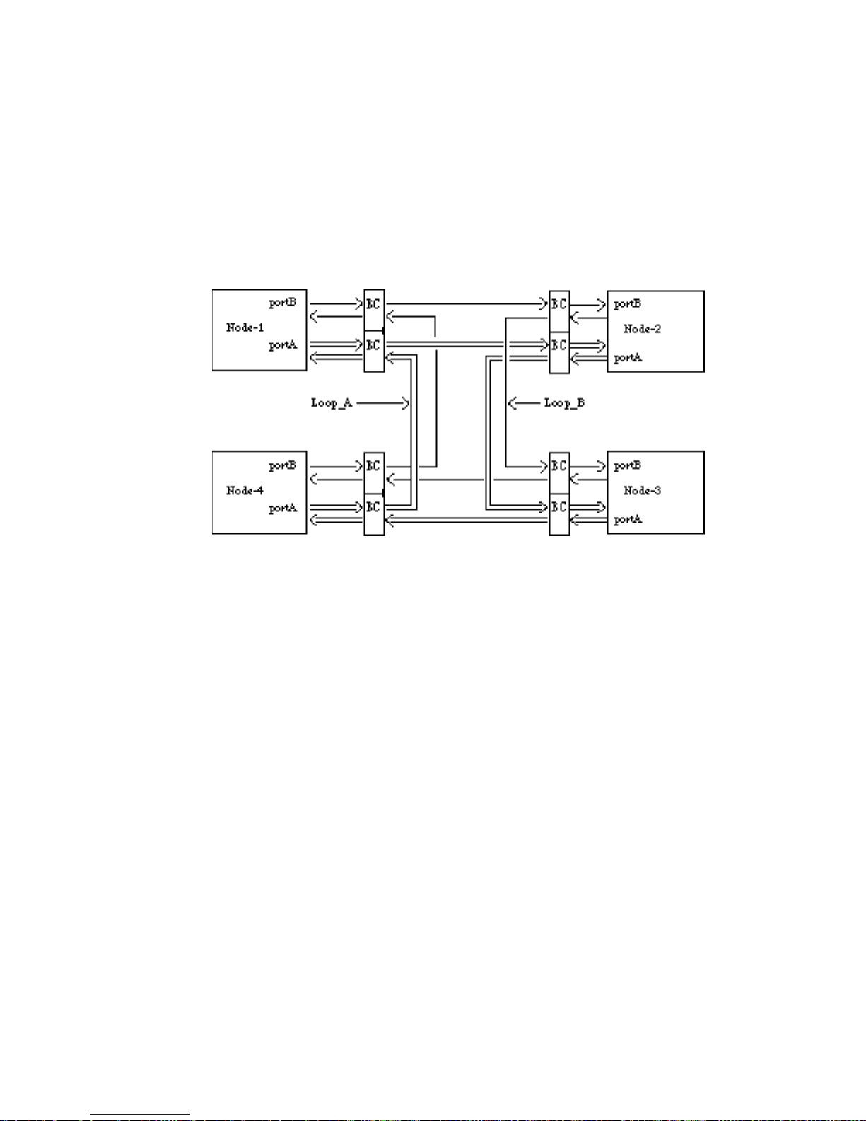
Figure 1.1 shows the example of connection for disk drives in FC-AL.
Figure 1.1 Example of FC-AL connection
BC are port bypass circuits on the back plane commonly, where Node mean the Target or
initiator.
Each Loop signal is transmitted by one-way direction and made of electrical wires called
“link”.
Each node is connected to the loop vial the port which the node owns. Each port consists of
the receiver which receives information from the loop and the transmitter which sends
information.
In this example, each node has two ports building two independent loops. Information is
propagated between the nodes on the loop through serial signals.
This section describes the Node, Port, BC and link forming the above diagram and the signals
propagated on the link.
C141-E054-02EN1 - 2
Page 24
1.1.1 Node/Port
②
①
Any device connected to Fibre Channel topology is called “node”.
In the application of this drive, the drive itself and the initiator are the nodes.
Each node has at least one port to connect other nodes and the port is called N_port.
Especially, in FC-AL, the port is called “NL_Port” where “NL” stands for node loop.
The drive provides two ports and each port is connected to each FC-AL.
See Figure 1.1.
1.1.2 Link
Each port provides both Receiver and Transmitter.
The drive uses electrical wires (differential signal) to receive or transmit the information.
This pair of wires is called a “link”.
See Figure 1.1.
1.1.3 Arbitrated Loop
Arbitrated loops are defined as “private loop” or “public loop”.
Private loop has no FL_port (for fabric loop) and all nodes are NL_ports.
If there is a FL_port which is managing the loop, the loop is called a public.
This can connect up to 126 active NL_port and one FL_port to the same loop.
And the NL_ports use arbitration to establish a Initiator-Target connections.
See Figure 1.1.
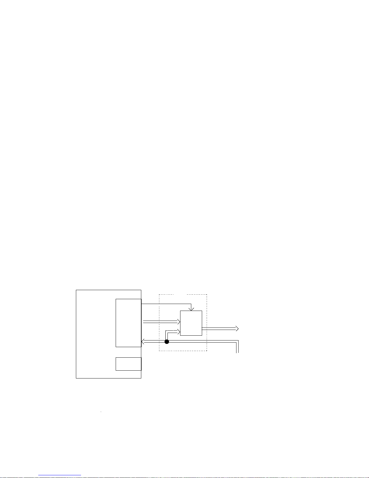
1.1.4 Port Bypass Circuit (BC)
Port bypass circuit is to bypass the drive if it cannot provide loop services.
For example, by removing the drive, unable to obtain valid data, or by any special condition.
The port bypass circuit is located external to the drive. (for example, on the back plane)
Figure 1.2 shows the relationship between the drive and the circuit.
Port_B
Select
AL-4/FC
drive
Output
Input
Port_A
Note
Select function is performed by “-EN port bypass A” and “-EN port bypass B”.
① Regular route (Bypass circuit off) ② Via bypass (Bypass circuit
BC
M
U
X
To next port
From previous port
Figure 1.2 Port Bypass Circuit
C141-E054-02EN 1 - 3
Page 25
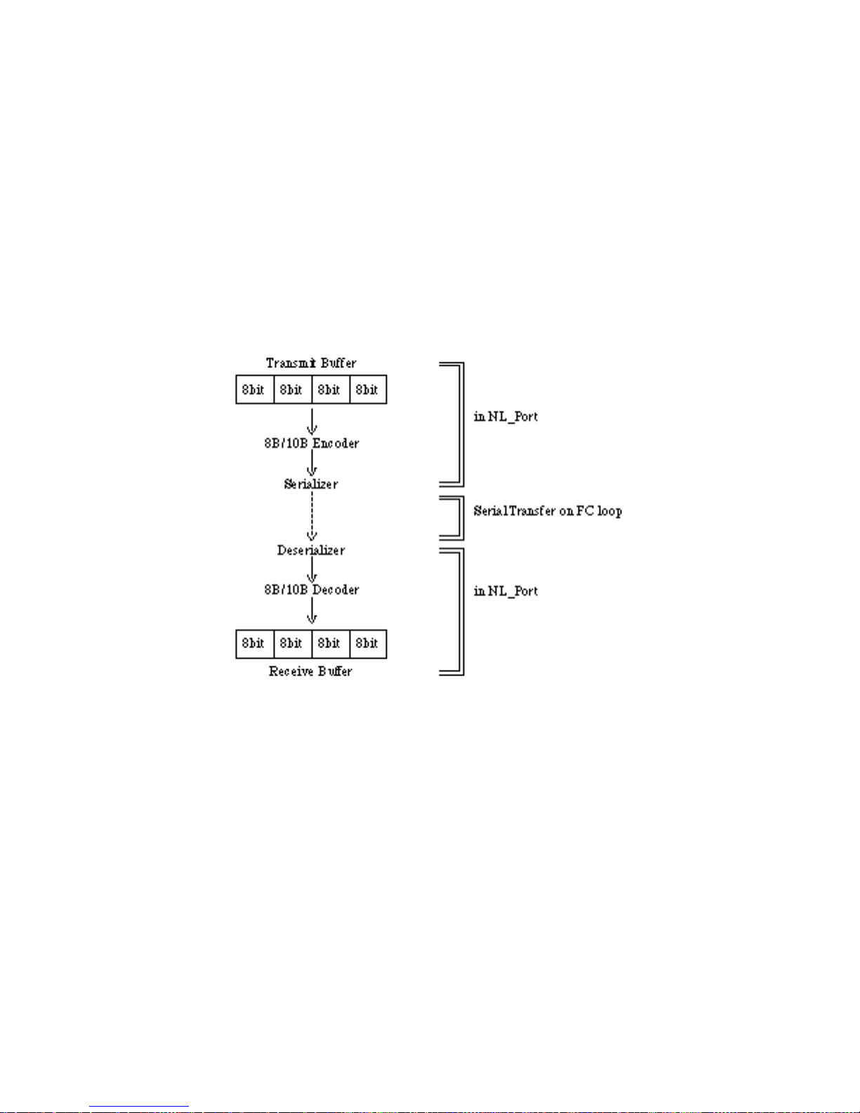
1.1.5 Encoding & Decoding
On FC-AL, the data is encoded prior to transmission and should be decoded when receiving.
The 10-bit character consists of 1,024 data space with 13-bit data mapped 1 control character.
This method is called 8B/10B encoding.
And to prevent too many same signal (ones or zeros), 10-bit character has an option to balance
total numbers of ones or zeros.
This balancing is called “running disparity”.
1.1.6 Buffer-to-buffer frame transfer
As shown in Figure 1.3, data transmission occurs from an output buffer in the node part to an
input buffer in the node port.
The basic unit of buffer-to-buffer transfer is the frame.
Figure 1.3 Buffer to Buffer Data Transfer
C141-E054-02EN1 - 4
Page 26

1.2 Information Transmitted on the Loop
Since information is exchanged between the ports through serial signals, both loop control
information and information at user level are defined in frame format.
The information on the loop is categorized into two groups.
One is “ordered sets” and the other is called “frame”.
Ordered sets consist of four 10-bit character to control port circuit mainly.
And the frame consists of FC-4 Device Data for SCSI protocol and Link Data to control Fibre
Channel layer.
The communication between the ports is done by using the frame defined in FC-PH.
The frame has the port address of source and destination, frame control information and user
protocol (SCSI-Command, data and etc.) information.
Table 1.1 shows category of the data on the loop.
Table 1.1 Data category on the Loop
Data Example
Ordered Sets
Frame Delimiters
Primitive Signals
Primitive Sequence
–SOF, EOF
–Idle, R_RDY, OPN, CLS
–LIP, LPE, LPB
Frame
Link Data
Basic Link Service
Extended Link Service
–ABTS, BA_ACC, BA_RJT
–PLOGI, PRLI, PDISC, LISM
FC-4 Device Data
Command Frame
Data Frame
Transfer-ready Frame
Response Frame
–FCP_CMND_IU
–FCP_DATA_IU
–FCP_XFER_RDY_IU
–FCP_RSP_IU
Note
a) Ordered Sets is mainly used for control of port circuit.
b) FC-4 Device Data is used for implementation SCSI protocol.
c) Link Data is used for transmission and response for port control data.
This section explains the “Ordered Sets” and “Frame” propagated on the loop.
C141-E054-02EN 1 - 5
Page 27

1.2.1 Ordered Sets (Refer to FC-PH, Section 11.4)
There are three kind of Ordered Sets.
(1) –Primitive signals
(2) –Frame delimiters
(3) –Primitive sequence
which consist of four 10 bit character combination.
Each ordered set has string of data shown in Figure 1.4.
The K28.5 special character is always used as the first character of all ordered sets.
Figure 1.4 Format of Ordered Sets
1.2.1.1 Primitive Signals
Primitive Signals have a control function to indicate status of the drive or to perform
some operation to the port being connected.
Primitive Signals are recognized when one ordered set is detected.
A minimum of six Primitive Signals must be transmitted between each frame.
The name and the function of Primitive Signals is below.
a) Idle ; to indicate the port can transmit or receive the frame
b) R_RDY ; to indicate the port has an area for receiving the frame
c) ARBx ; to request the right to use the loop. x = AL_PA of the requesting
port
d) ARB (FO) ; to request the right (= lowest priority) to use the loop
e) OPN ; to inform the transmission of the frame to the destination port
f) CLS : to inform the release of the loop
1.2.1.2 Frame Delimiters
Frame Delimiters mark the beginning and end of frames.
They are called Start-of-frame (SOF) delimiters and End-of-frame (EOF) delimiters.
1.2.1.3 Primitive Sequence
Primitive Sequence is a control function and requires to be detected.
The name and the function of Primitive sequence is below.
a) LPB ; When received, the drive enables the port bypass circuit and bypasses
b) LPE ; When received, the drive disables the port bypass circuit and connects to
the loop.
the loop.
C141-E054-02EN1 - 6
Page 28

1.2.2 Frame Structure (Refer to FC-PH, Chapter 17)
A frame format is shown in Figure 1.5.
4
SOFfill words
1word count
24
Header
0-2048+64 (optional header)
PayloadFrame
0-5286
4
4
1
1
min24byte count
fill wordsEOFCRC
min6
Figure 1.5 Frame Format
a) SOF ; Start of frame indicates the beginning of the frame.
b) Frame Header ; Used as link control, drive protocol transfer and detect error condition.
The frame header format is listed in Table 1.2.
Table 1.2 Frame header format
word/byte 0 (bits 31 – 24) 1 (bits 23 – 16) 2 (bits 15 – 08) 3 (bits 07 – 00)
0 R_CTL D_ID
1 reserved S_ID
2 TYPE F_CTL
3 SEQ_ID DF_CTL SEQ_CNT
4 OX_ID RX_ID
5 OFFSET
R_CTL ; Routing Control to categorize the frame.
D_ID ; Destination Identifier, N_port address to which the frame is being sent.
S_ID ; Source Identifier, N_port address originating the frame.
TYPE ; Data Structure Type, identifies the frame protocol.
F_CTL ; Frame Control information
SEQ_ID ; Sequence Identifier, uniquely identifies frames in a non-streamed sequence.
DF_CTL ; Data Field Control, specifies the optional headers in the payload.
This field is not supported by the drive and used as 00h.
SEQ_CNT ; Sequence Count, identifies the order of the frames.
OX_ID ; Originator Exchange Identifier, assigned by the originator of an exchange.
This value is similar to Queue Tag in SCSI and must be unique for a
pair between the intiator and the drive.
RX_ID ; Responder Exchange Identifier, generated by the responder for a exchange.
OFFSET ; Defines the relative displacement of the first byte of the payload from
the base address of the command.
c) Payload ; Data field, must be multiple of four bytes.
–If the frame is FC-4 Device Data, the payload has SCSI CDB,
Read/Write Data or status/sense information.
–If the frame is Link Data, the payload has control information for the
drive or the response data to the initiator.
d) CRC ; Calculates without including SOF and EOF delimiters.
e) EOF ; End of frame indicates the end of a frame.
C141-E054-02EN 1 - 7
Page 29

(1) Link Data
Link Data is used when the initiator transmit control code to the target or when the
target responsds to the iniator.
Link Data supported by the drive are listed below.
1. Basic link service
a) Abort Sequence
b) Basic_Accept
c) Basic_Reject
ABTS ; SCSI-2 Abort Tag
BA_ACC; accept response to the abor
BA_RJT ; reject response to the abort
2. Extended link service
a) N_Port login
PLOGI ; declare the initiator access the
target
b) Logout
LOGO ; declare the initiator finished
accessing the target
c) Process Login
PRLI ; PRLI is send by the initiator
to a target to establish the
SCSI FCP operating features.
d) Process Logout
PRLO ; declare the initiator finished
accessing the target
e) Port Discovery
PDISC ; issued by the initiator to
verify the address of the target
after Loop initialization
f) Address Discovery
g) Reinstate Recovery Qualifier
ADISC ; same as PDISC
RRQ ; issued by the initiator after
processing ABTS
h) Read Link Status
RLS ; Request Link Error Status
Block
i) Third-Party Process Layout
TPRLO ; declare the initiator finished
accessing the target
j) Accept
ACC ; response to the Link service
received
k) Link Service Reject
LS_RJT ; reject to the Link service
received.
l) Loop Initialization Select Master
m) Loop Initialization Fabric Assigned
n) Loop Initialization Previously
LISM ; see 1.4.1 Loop Initialization
LIFA ; see 1.4.1 Loop Initialization
LIPA ; see 1.4.1 Loop Initialization
Acquired
o) Loop Initialization Hard Assigned
p) Loop Initialization Soft Assigned
q) Loop Initialization Report Position
r) Loop Initialization Loop Position
LIHA ; see 1.4.1 Loop Initialization
LISA ; see 1.4.1 Loop Initialization
LIRP ; see 1.4.1 Loop Initialization
LILP ; see 1.4.1 Loop Initialization
C141-E054-02EN1 - 8
Page 30
(2) FC-4 Device Data
Exchanges consist of two or more frame sequences between the initator and the target.
Exchanges starts from command frame by the initiator and ends at response frame by
the target.
Four FC-4 Device Data (FCP_CMND_IU, FCP_XFER_RDY_IU, FCP_DATA_IU,
FCP_RSP_IU) are used to implement SCSI protocol. Figure 1.6 explains the
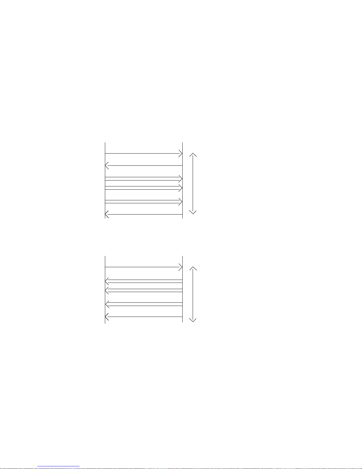
examples of Exchanges in case of SCSI write/read operation.
a) SCSI write operation
Target (drive)Initiator
1)
2)
3)
FCP_CMND_IU (WT)
FCP_XFER_RDY_IU
FCP_DATA_IU (Write)
:
FCP_RSP_IU4)
b) SCSI read operation
1)
3)
FCP_CMND_IU (RD)
FCP_DATA_IU (Read)
:
FCP_RSP_IU4)
Exchange ; from command frame to response frame
Target (drive)Initiator
Exchange ; from command frame to response frame
1) FCP_CMND_IU ; includes SCSI command and the control information
2) FCP_XFER_RDY_IU ; permits the data transmission from the initiator to the drive
3) FCP_Data_IU ; Read or Write data between the initiator and the drive
4) FCP_RSP_IU ; Used by the drive to report status/sense data to the initiator
Figure 1.6 Examples of Exchange
C141-E054-02EN 1 - 9
Page 31

1.3 Physical Requirements, Electrical Requirements
ESD contact
1.3.1 Interface connector
The connector for the fibre channel loop bus is an unshielded SCA-2 connector conforming to
SCSI-3 type which has two 20-pin rows spaced 1.27 mm (0.05 inch) apart. Figure 1.7 shows
the fibre channel connector. See Section 1.3.2, 1.3.3 for signal assignments on the connector.
Figure 1.7 SCA2 type interface connector (IDD)
C141-E054-02EN1 - 10
Page 32

Figure 1.8 Locations of connectors
Pin
Pin
Pin 2
Pin 1
Table 1.3 FC-SCA connector: CN1
Pin No. Signal Signal Pin No.
01 –EN bypass port A +12V charge 21
02 +12V GND 22
03 +12V GND 23
04 +12V +PortA_in 24
05 –Parallel ESI –PortA_in 25
06 –Drive present GND 26
07 Active LED out +PortB_in 27
08 –Spindle sync –PortB_in 28
09 Start_1/Mated GND 29
10 Start_2/Mated +PortA_out 30
11 –EN bypass port B –PortA_out 31
12* SEL_6 –DSK_WR GND 32
13* SEL_5 –DSK_RD +PortB-out 33
14* SEL_4 –ENCL_ACK –PortB-out 34
15* SEL_3 D(3) GND 35
16 Fault LED out SEL_2 D(2) 36*
17 N.C SEL_1 D(1) 37*
18 N.C SEL_0 D(0) 38*
19 +5V N.C 39
20 +5V +5V charge 40
Note: *1) Signal names in the right column of the table are those in parallel ESI operation.
C141-E054-02EN 1 - 11
Page 33

1.3.2 Signal function in SFF8045 mode
(1) +12V charge, +5V charge
These signals are used to precharge of the internal circuits to avoid excessive surge current
while hot plugging is being operated.
Before power voltage pins (+12V and +5V) make contact, these precharge pins mate early.
Precharge control circuits are external to the drive.
The voltage provided to the precharge signals are defined in Table 1.4.
Table 1.4 Charge supply to the drive
Charge Signal Range of power supply
+12V charge 12V +5%, –12% 6 Amps 1 Amps
+5V charge 5V +5%, –17% 6 Amps 1 Amps
(2) Fault LED out
The drive starts, and this signal lights when it detects internal failure.
The Fault LED out signal is an open-collector output.
The LED and the current limiting register are external to the drive.
See Table 1.5.
LED off
LED on IOL > 30mA 0 < VOL <0.5V
Max Surge to the drive Max Continuous
after charge complete
required the drive
Table 1.5 Characteristics of Fault LED out signal
State Current Output Voltage
–100µA <IOH < 100µA
(3) Active LED out
The signal indicates that the drive starts and is active.
Two alternative indication pattern is defined in SFF-8045 Specification Rev 3.7.
One is “hot plug implementation” for the drives in hot plugged environments.
The other is “legacy implementation” where the compatibility with previous SCSI indication
system is required.
C141-E054-02EN1 - 12
Page 34

The drive supports hot plug implementation described below. [TBD]
a) The Active LED out signal does not light if the drive is not connected.
b) The Active LED out signal blinks for approximately 0.5 sec. intervals when the drive is
spinning. It turns to light when the drive is ready.
c) The Active LED out signal blinks for approximately 0.5 sec. intervals when the drive is
spin-down. It is turned off when the drive is not ready.
d) The Active LED out signal is turned off when the SCSI command is received by the drive
and during processing. And it changed to blink when the command processing is
completed.
(4) Start_1/Mated, Start_2/Mated
These signals controls the method to start the drive’s motor as described Table 1.6.
Also the signals are used to indicate to the drive that the drive has been mated to a backplane.
Table 1.6 Definition of motor start/mated control
Start_2/
Mated
open
Start_1/
Mated
open
Function
Drive is not mated to a backplane. The drive’s motor does NOT spin
up.
open
ground
Drive is mated to a backplane. The drive’s motor spins up when the
drive receives SCSI start command after a mating deskew time has
passed.
ground
open
Drive is mated to a backplane. The drive’s motor spins up after a
delay after a mating deskew time has passed.
ground
ground
Drive is mated to a backplane. The drive’s motor spins up
immediately after a mating deskew time has passed.
The mating deskew time is minimum 250 msec.
A 10 KΩ pull up register to 5V for each signal is asserted on the drive.
The open and ground states should be controlled as in Table 1.7.
Table 1.7 Electric requirement for input control
State Current Voltage
open
20 µA <IIH < 20 µA
2.2V <VIH < 5.25V
ground 0 <IIL <–20 mA –0.5V <VIL <0.7V
(5) –Parallel ESI
This signal in SFF8045 mode is not supported by the drive.
C141-E054-02EN 1 - 13
Page 35

(6) SEL_0, _1, _2, _3, _4, _5, _6
These seven SEL lines are provided for the binary value of the loop identifier by the
backplane.
This identifier is name AL_PA and is used for 126 unique value except 00h.
These ID signals are tested by the drive when powered on.
SEL_6 is the most significant bit and SEL_0 is the elast significant bit.
Electric requirement for the signals is listed in Table 1.8.
These signals with high state have approximately 10KΩ register on the backplane.
Table 1.8 Electric requirement for SEL_n inputs
State Current Voltage
high
low
–20 µA <IIH < 20 µA
–20 µA <IIL < 20 µA
2.2V <VIH < 5.25V
–0.5V <VIL <0.7V
SEL. ID = (SEL_6, SEL_5, SEL_4, SEL_3, SEL_2, SEL_1, SEL_0)
C141-E054-02EN1 - 14
Page 36

Table 1.9 Arbitrated loop physical address (AL_PA) values
AL_PA
(hex)
SEL ID
(hex)
AL_PA
(hex)
SEL ID
(hex)
AL_PA
(hex)
SEL ID
(hex)
EF 00 A3 2B 4D 56
E8 01 9F 2C 4C 57
E4 02 9E 2D 4B 58
E2 03 9D 2E 4A 59
E1 04 9B 2F 49 5A
E0 05 98 30 47 5B
DC 06 97 31 46 5C
DA 07 90 32 45 5D
D9 08 8F 33 43 5E
D6 09 88 34 3C 5F
D5 0A 84 35 3A 60
D4 0B 82 36 39 61
D3 0C 81 37 36 62
D2 0D 80 38 35 63
D1 0E 7C 39 34 64
CE 0F 7A 3A 33 65
CD 10 79 3B 32 66
CC 11 76 3C 31 67
CB 12 75 3D 2E 68
CA 13 74 3E 2D 69
C9 14 73 3F 2C 6A
C7 15 72 40 2B 6B
C6 16 71 41 2A 6C
C5 17 6E 42 29 6D
C3 18 6D 43 27 6E
BC 19 6C 44 26 6F
BA 1A 6B 45 25 70
B9 1B 6A 46 23 71
B6 1C 69 47 1F 72
B5 1D 67 48 1E 73
B4 1E 66 49 1D 74
B3 1F 65 4A 1B 75
B2 20 63 4B 18 76
B1 21 5C 4C 17 77
AE 22 5A 4D 10 78
AD 23 59 4E 0F 79
AC 24 56 4F 08 7A
AB 25 55 50 04 7B
AA 26 54 51 02 7C
A9 27 53 52 01 7D
A7 28 52 53
A6 29 51 54
A5 2A 4E 55
C141-E054-02EN 1 - 15
Page 37

(7) Port out (+Port A_out, +Port B_out)
Port out signals are output by the drive.
These signals are differential copper with a termination of 75 Ω and there is a termination of
150 Ω to output ECL signal label on the loop .
The output circuit is shown in Figure 1.9.
Comparable
to VSC7125
Figure 1.9 Fibre Channel output circuit
(8) Port in (+Port A_in, +Port B_in)
These signals are differential copper with 150 Ω termination and are AC coupled with
capacitors.
The input circuit is shown in Figure 1.10.
(9) A, B
These Enable Port Bypass Circuit (PBC) by a bypass signals, which is located external to the
drive.
The functional diagram of these signals is described in Section 1.1.4.
When the drive asserts this signal (low), the Port bypass circuit bypasses the drive which is
connected.
This signal is asserted when;
+Port in
outside of
the drive
–Port in
0.001uF
0.001uF
RX
150 Ω
RY
Figure 1.10 Fibre Channel input circuit
a) detecting of the Loop Port Bypass primitive sequence
b) being removed of the drive from the loop
c) loss of receive clock
d) loss of transmission clock
e) detecting hardware error within the drive
Comparable
to VSC7125
This signal is negated when the drive detects a Loop Port Enable primitive sequence.
C141-E054-02EN1 - 16
Page 38

(10) –Drive present ; This signal connected to the ground.
1.3.3 Signal function in SFF8067 mode
(1) –Parallel ESI
–Parallel ESI signal is used to request the enclosure to provide the SEL_x (x = 0-6) addressing
signals and to request ESI block Read/Write operation.
Table 1.9 defines electronic characteristics of this signal.
Table 1.10 Output Characteristics of –Parallel ESI
State Current Drive Available Output Voltage
high
–100 µA <IOH < 100 µA
0< VOH <5.25V
low IOL >1.6 mA 0< VOL <0.5V
Table 1.10 shows how –Parallel ESI signal is used in the Enclosure Service Interface.
(2) –DSK_WR, DSK_RD, ENCL_ACK, D(3), D(2), D(1), D(0)
The SEL_x (x = 0-6) signals change into communication control signals when –Parallel ESI
signal is asserted.
C141-E054-02EN 1 - 17
Page 39

1.4 Drive Operation on the Loop
This section describes the following as the operations which the drive is required to perform at
FC level:
– Loop initialization
– Arbitration
– Communication between the initiator and target
1.4.1 Loop Initialization
(1) Process Outline
Loop Initialization is a process for the purpose listed below.
– To obtain Arbitrated Loop Physical Address (AL_PA) because the drive has no valid
address when powered on.
– To indicate the error on the loop to the other NL_ports.
– To reset particular drive by the initiator.
And the trigger to start Loop Initialization is called LIP.
Loop Initialization is occurred as follows.
a) The drive is powered on.
b) The drive (or all NL_Ports if powered on simultaneously) requests to start Loop Initialization.
; see 1.4.1(3) (LIP)
c) Select loop master (responsible for processing Loop Initialization)
; see 1.4.1(4) (LISM)
d) Each NL_ports on the loop starts the process for obtaining AL_PA.
; see 1.4.4(5) (LIFA/LIPA/LIHA/LISA)
e) Each NL_Ports obtains unique AL_PA and Loop Initialization is terminated.
C141-E054-02EN1 - 18
Page 40

(2) AL_PA
This sub-section describes the addresses (AL_PA) used on the loop.
AL_PA is a 8-bit character and when encoded to 10 bits, AL_PA has an equal number of ones
or zeros to maintain neutral running disparity.
Table 1.11 shows the AL_PA values and the priority used on the loop.
Details of AL_PA is described in Table 1.9.
Values (hex) Priority & Use
00 Highest priority and assigned for FL_port.
01-EF 126 valid NL_Port address
F0 Has no priority and used for fairness algorithm and for Loop
Table 1.11 AL_PA value/priority
The drive does not assume the existence of this value on the loop.
(because of assuming private loop)
01 (highest priority) < ===== > EF (Lowest priority)
Initialization process
F1-F6 not used
F7, F8 reserved for Loop initialization
others not used
Most common method for the disk drive will be to have the backpanel provide a hard assigned
address.
If the drive failed to obtain a hard assigned address, the drive would obtain the address by soft
assigned method. For details, refer to sub-section (5).
C141-E054-02EN 1 - 19
Page 41

(3) LIP (Loop Initialization on Primitive)
Loop Initialization is generated by sending any LIPs in Table 1.12.
The NL_Port which received a LIP then transmit the LIP to the next port on the loop.
This cycle terminates when the NL_Port that started the initialization process receives the LIP.
Table 1.12 LIP sequences
LIP type Use Description
LIP (F7, F7)
LIP (F7, AL_PS)
Initializing
Loop
LIP (AL_PD, AL_PS) Reset the port The source port (AL_PS) requests to reset the
LIP (F8, AL_PS) Loop failure The NL_Port has detected an input failure
LIP (F8, F7) Loop failure The NL_Port has detected an input failure and
Note:
*1: The drive can issue the LIP.
*2: The drive receives the LIP but does NOT issue LIP (AL_PD, AL_PS).
(4) LISM (Loop Initialization Select Master)
This sub-section describes a process to select the loop master to which the function for
proceeding with each process of Loop Initialization is given.
A NL_Port requests to obtain AL_PA *1
*2
destination port (AL_PD).
The selected port performs to reset after loop
initialization.
*1
AL_PS is the AL_PA of the source port.
*1
the port could not obtain an AL_PA.
Selecting the loop master proceeds as follows. (Figure 1.11)
Figure 1.11 shows the example that three ports exist on the loop and each port has an unique
Port Name which algebraic relationship is n+2>n+1>n.
Steps [1] through [6] are for selecting a port with the smallest unique port name of those
assigned at manufacture, as the loop master.
Steps [8] and [9] are for confirming that the port, which became the loop master by steps [1]
through [6], has become the loop master again.
C141-E054-02EN1 - 20
Page 42

Step Port Name n n+1 n+2
[1] Transmits LISM with its own port
name to the next port.
[2] Receives LISM from the upper
loop port.
LISM (n+2) LISM (n) LISM (n+1)
[3] Compares the port name with its
own port name and transmits
LISM with lower port name.
[4] Receives LISM from the upper
loop port.
LISM (n+1) LISM (n) LISM (n)
[5] Compares the port name with its
own port name and transmits
LISM with lower port name.
[6] Receives LISM from the upper
loop port.
LISM (n) LISM (n) LISM (n)
LISM (n) LISM (n+1) LISM (n+2)
LISM (n) LISM (n) LISM (n+1)
LISM (n) LISM (n) LISM (n)
[7] Compares the port name with its
own port name and if they are the
same, the port becomes loop
master.
[8] Loop master transmits ARB (F0)
ans waits for the ARB (F0) comes
back.
[9] Loop master checks ARB (F0)
ARB (F0)
Note:
The value is assigned to each port uniquely in production.
Figure 1.11 Process for selecting Loop master
<non loop master><non loop master><loop master>
ARB (F0)
C141-E054-02EN 1 - 21
Page 43

(5) LIFA/LIPA/LIHA/LISA
This sub-section describes a process for each port to obtain AL_PA.
Figure 1.12 shows the process for non loop master to obtain unique AL_PA after ending a
process for selecting the loop master.
Loop Master
LIFA
LIPA
LIHA
LISA
LIRP
Other NL_Port on the loop
; LIFA is used to gather all fabric-assigned AL_PAs.
; LIPA is used to gather all previously-acquired AL_PAs.
The drive attempts to obtain same AL_PA if the drive
obtained the AL_PA in previous initilization.
; LIHA is used to gather all hard assigned AL_PAs.
The drive attempts to obtain AL_PA if it failed to obtain
AL_PA in LIPA.
The drive always attempts to obtain AL_PA when
a) powered on or
b) receiving LIP (AL_PD, AL-PS)
The drive always attempts to obtain same AL_PA.
; LISA is used to assign any remaining AL_PA bits.
The drive attempts to obtain AL_PA if it failed up to
LIHA.
If the drive fails to obtain AL_PA in LISA, then the drive
<== Each NL_Port obtains unique AL_PA here.
<== LIRP and LILP may be caused by the loop master to
confirm the location and address on the loop.
LILP
; LIRP is used to record the relative positions on the loop.
; LILP is used to inform all NL_Ports of their relative
positions on the loop from the loop master.
CLS
Figure 1.12 Loop Master Operation
The abbreviation in this section is below.
LIFA ; Loop Initialization Fabric Assigned
LIPA ; Loop Initialization Previously Acquired
LIHA ; Loop Initialization Hard Assigned
LISA ; Loop Initialization Soft Assigned
LIRP ; Loop Initialization Report Position
LILP ; Loop Initialization Loop Position
C141-E054-02EN1 - 22
Page 44

1.4.2 Arbitration
For information to be exchanged between the ports connected to a loop, generally the two
ports (send side and receive side) must occupy the loop (placed in point-to-point connection
state).
Arbitration is a process to win access right on the loop and must be done before
communicating with another port.
When the arbitration is finished, only a pair of a initiator and a target can communicate each
other on the loop.
The drive supports the method called “Access fairness”.
The process on the port supporting fairness movement is below.
a) If two or more ports request to arbitrate, the port with the highest priority (the port with
smallest AL_PA value) wins the arbitration.
b) The port once won the arbitration cannot participate in the arbitration until other port wins
the arbitration and release the loop.
This method protects that the same port uses the loop consecutively.
C141-E054-02EN 1 - 23
Page 45

1.4.3 Communication between Initiator and Target
This section shows the figure of the protocol using FC-4 Device Data on Fibre Channel layer.
The following procedures are followed to send FC-4 device data.
- Issue ARB by which the source of FC-4 device data asserts the occupation of the loop.
- After occupying the loop, the source issues “Open” to the destination.
- The receiving station responds by R_RDY by the count by which it can receive FC-4 device data.
- The sending station sends FC-4 device data.
- The sending station sends CLS to terminate the occupation of the loop.
A description of each FC-4 device data follows.
(1) Command Transfer
TargetInitiator
ARBx
OPN
R_RDY
FCP_CMND_IU
CLS
When the initiator issues FCP_CMND_IU:
Figure 1.13 Command Transfer
(2) Transfer Ready (X_RDY), Response Transfer (RSP)
TargetInitiator
ARBx
OPN
R_RDY
FCP_XFER_RDY_IU or
FCP_RSP_IU
When the target issues FCP_XFER_RDY_IU
or FCP_RSP_IU
CLS
Figure 1.14 Transfer Ready (X_RDY), Response Transfer (RSP)
C141-E054-02EN1 - 24
Page 46

(3) Write Data Transfer
TargetInitiator
FCP_Data_IU
(4) Read Data Transfer
ARBx
OPN
R_RDY
R_RDY
R_RDY
R_RDY
Write Data 1
R_RDY
Write Data 3
Write Data 4
CLS
Figure 1.15 Write Data Transfer
When the target recognizes the sending of
write data
ARBx
OPN
R_RDY
Read Data 1
R_RDY
Read Data 2
R_RDY
:
Read Data n
CLS
TargetInitiator
When the targetsends read data:
Figure 1.16 Read Data Transfer
C141-E054-02EN 1 - 25
Page 47

1.5 Ordered Sets (Refer to FC-PH, Section 11.4 and FC-AL, Chapter 6)
Table 1.13 shows the Ordered Sets specification.
This section describes handling of the Ordered Sets of this drive.
Table 1.13 Ordered Sets Specification
No. Frame Delimiters Symbol The drive can;
01
SOF Connect Class 1
02
SOF Initiate Class 1
03
SOF Normal Class 1
04
SOF Initiate Class 2
05
SOF Normal Class 2
06
SOF Initiate Class 3
07
SOF Normal Class 3
08
SOF Initialize Loop
09
EOF Terminate
10
EOF Disconnect-Terminate
11
EOF Abort
12
EOF normal
13
EOF Disconnect-Terminate-
SOFc1
SOFi1
SOFn1
SOFi2
SOFn2
SOFi3
SOFn3
SOFil
EOFt
EOFdt
EOFa
EOFn
EOFdti
receive only (discard)
receive only (discard)
receive only (discard)
receive only (discard)
receive only (discard)
receive or transmit
receive or transmit
receive or transmit
receive or transmit
receive only (discard)
receive only (discard)
receive or transmit
receive only (discard)
Invalid
14
EOF Normal-Invalid
EOFni
receive only (discard)
No. Primitive Signals
01
Idle
02
Receiver_Read
03
Arbitrate
04
Arbitrate
05
Open full-duplex
06
Open half-duplex
07
Open broadcast replicate
08
Open selective replicate
09
Slotted Loop – transfer
10
Slotted Loop – isoch
11
Slotted Loop – asynch
12
Close
13
Mark
Idle
R_RDY
ARBx
ARB (F0)
OPNyx
OPNyy
OPNfr
OPNyr
SLPyx
SLPyf
SLPff
CLS
MRKtx
receive or transmit
receive or transmit
receive or transmit
receive or transmit
receive only
receive or transmit
receive only (discard)
receive only (discard)
receive only (discard)
receive only (discard)
receive only (discard)
receive or transmit
receive only (discard)
No. Primitive Sequences
01
Offline
02
Not_Operational
03
Link_Reset
04
Link_Reset_Response
05
Loop Initialization
06
Loop Initialization
07
Loop Initialization
08
Loop Initialization
09
Loop Initialization
10
Loop Port Enable
11
Loop Port Enable all
12
Loop Port Bypass
OLS
NOS
LR
LRR
LIP (F7, F7)
LIP (F7, x)
LIP (F8, F7)
LIP (F8, x)
LIPyx
LPEyx
LPEfx
LPByx
receive only (discard)
receive only (discard)
receive only (discard)
receive only (discard)
receive or transmit
receive or transmit
receive or transmit
receive or transmit
receive only
receive only
receive only (discard)
receive only
C141-E054-02EN1 - 26
Page 48

1.6 Basic Link Service
This section defines handling of the link service of this drive and handling of each frame.
Table 1.14 shows the Link Data specification
No. Basic Link Service Symbol The drive can;
01
No Operation
02
Abort Sequence
03
Basic Accept
04
Basic Reject
Table 1.14 Basic Link Data Specification
NOP
ABTS
BA_ACC
BA_RJT
receive only (discard)
receive only
transmit if only the drive received ABTS
transmit if only the drive received ABTS
C141-E054-02EN 1 - 27
Page 49

The Basic Link Services supported by this drive are the Abort Sequence (ABTS) and its
responses, Basic Accept (BA_ACC) and Basic Reject (BA_RJT). Other Basic Link Services
are discarded.
The header field of the Basic Link Service is defined below.
Word 0 1 2 3 Byte
Header0<R_CTL>
8x
1 Reserve <S_ID>
2 <TYPE>
00
3 <SEQ_ID><DF_CTL> <SEQ_CNT>
4 <OX_ID> <RX_ID>
5 <Parameter>
<D_ID>
<F_CTL>
(1) R_CTL.. (Routing Control)
The high order four bits (8h) represent Basic
Link Service, and the low order four bits each
Basic Link Service.
(2) D_ID.. (Destination Identifier)
• Address of the drive which receives ABTS.
• Address of the initiator for a response to
ABTS.
(3) S_ID.. (Source Identifier)
• Address of the initiator which sends
ABTS.
• Address of the drive for a response to
ABTS.
(4) Type
The Basic Link Service uses 00h.
(5) F_CTL.. (Frame Control)
• Set 09000000h for the transmission of
ABTS.
(Originator of Exchange, Last Data Frame
of Sequence, Transfer Sequence Initiative)
• Set 99000000h for a response to ABTS.
(Responder of Exchange, Last Sequence of
Exchange)
(6) SEQ_ID.. (Sequence Identifier)
The drive does not check this item. For a
response to ABTS, respond with the same
SEQ_ID as received.
(7) DF_CTL.. (Data Field Control)
Set 00h because no optional header is used.
(8) SEQ_CNT.. (Sequence Count)
Set 0000h to indicate the first frame of a
sequence.
C141-E054-02EN1 - 28
Page 50

1.6.1 Abort Sequence (ABTS)
(9) OX_ID.. (Originator Exchange Identifier)
• Assigned for the initiator to begin the
exchange of ABTS.
• For a response to ABTS, respond with the
same OX_ID as received.
(10) RX_ID.. (Responder Identifier)
Set FFFFh to indicate that RX_ID is unused.
(11) Parameter
Unused in the Basic Link Service.
ABTS
0 1 2 3 Byte
Word
Header0<R_CTL>
81 ××
1 Reserve
00 ××
2 <TYPE>
00 09
3 <SEQ_ID
>
××
4
×× ×× FF FF
5
00 00 00 00
FC-PH 21.2.2
<SOF>
<DF_CTL>
00 00 00
<CRC>
<EOF>
<D_ID>
×× ××
<S_ID>
×× ××
<F_CTL>
00 00
<SEQ_CNT>
<RX_ID><OX_ID>
The initiator issues an Abort Sequence (ABTS) to
abort one SCSI Exchange (SCSI CMD) or FC
Exchange (one link service). For the header field,
refer to Section 1.6, "Basic Link Service."
As shown in the figure for the Abort Sequence
frame, this ABTS frame has no payload. The
ABTS frame has a value of 81h in R_CTL of the
header.
C141-E054-02EN 1 - 29
Page 51

1.6.2 Basic Access (BA_ACC)
BA_ACC
0 1 2 3 Byte
Word
Header0<R_CTL>
84 ××
1 Reserve
00 ××
2 <TYPE>
00 99
3 <SEQ_ID
>
××
4
×× ×× FF FF
5
00 00 00 00
Payload
0 00 00 00 00
1
×× ×× ×× ××
2 Low SEQ_CNT High SEQ_CNT
FC-PH 21.2.3
<SOF>
<D_ID>
<S_ID>
<F_CTL>
<DF_CTL>
00 00 00
<OX_ID>
FC-PH T.58
OX_ID RX_ID
<CRC>
<EOF>
×× ××
×× ××
00 00
<SEQ_CNT>
<RX_ID>
Reserve
The drive responds with BA_ACC to the initiator
when the received ABTS frame is correct.
The payload field of the BA_ACC frame is
described below. For the header field, refer to
Section 1.6, "Basic Link Service."
Word xx/ and byte y of the payload are represented
by [PL:Wxx/By].
(1) SEQ_ID Valid.. (Routing Control)
[PL:W00/B0]
00h: Indicates that the SEQ_ID of last sequence
of word 0/byte 2 is invalid.
(2) Last SEQ_ID.. (SEQ_ID of last sequence)
[PL:W00/B1]
00h: Invalid according to the setting in (1).
(3) OX_ID.. (Originator Exchange Identifier)
[PL:W01/B0-1]
Same value as OX_ID received for ABTS.
(4) RX_ID.. (Originator Exchange Identifier)
[PL:W01/B2-3]
Same value as RX_ID received for ABTS.
(FFFFh)
C141-E054-02EN1 - 30
Page 52

1.6.3 Basic Reject (BA_RJT)
BA_RJT
0 1 2 3 Byte
<SOF>
<R_CTL>
85 ××
Reserve
00 ××
<TYPE>
00 99
<SEQ_ID
>
××
<OX_ID>
×× ×× FF FF
00 00 00 00
Reserve T.59
FC-PH 21.2.4
<D_ID>
×× ××
<S_ID>
×× ××
<F_CTL>
<DF_CTL>
00 00
<SEQ_CNT>
00 00 00
FC_PH F.57
T.60
Reason
Explanation
<CRC>
<EOF>
Vendor
The drive responds with BA_RJT to the initiator
when RX_ID of the received ABTS frame is not
FFFFh.
The payload field of the BA_RJT frame is
described below. For the header field, refer to
Section 1.6, "Basic Link Service."
Word xx/ and byte y of the payload are represented
by [PL:Wxx/By].
(1) Reason Coded [PL:W00/B1]
03h: Logical error code returned when RX_ID
of ABTS is not FFFFh.
(2) Reason Explanation [PL:W00/B2]
03h: Code of invalid OX_ID-RX_ID
combination.
(3) Vender Unique (PL:W00/B3]
00h: Not supported by the drive.
C141-E054-02EN 1 - 31
Page 53

1.7 Extended Link Service
Table 1.15 Extended Link Data Specification
No. Extended Link Service Symbol The drive can;
01
N_Port Login
02
Logout
03
Process Login
04
Process Logout
05
Read Link Status
06
Reinstate Recovery Qualifier
07
Port Discovery
08
Address Discovery
09
Third-Party Process Logout
10
Accept
11
Link Service Reject
The Extended Link Services supported by this drive are the Link Service Command and its
responses, Accept (ACC) and Link Service Reject (LS_RJT).
The header field of the Extended Link Service is defined below.
PLOGI
LOGO
PRLI
PRLO
RLS
RRQ
PDISC
ADISC
TPRLO
ACC
LS_RJT
receive only
receive or transmit
receive only
receive or transmit
receive only
receive only
receive only
receive only
receive only
transmit if only received Extended Link
transmit if only received Extended Link
Service was illegal or has fails.
Word 0 1 2 3 Byte
Header0<R_CTL>
2x
1 <S_ID>
2 <TYPE>
01
3 <SEQ_ID><DF_CTL> <SEQ_CNT>
4 <OX_ID> <RX_ID>
5 <Parameter>
<D_ID>
<F_CTL>
(1) R_CTL.. (Routing Control)
The high order four bits (2h) represent
Extended Link Service, and the low order four
bits each Extended Link Service.
(2) D_ID.. (Destination Identifier)
• Destination address for the frame.
(3) S_ID.. (Source Identifier)
• Source address for the frame.
(4) Type
The Extended Link Service uses 01h.
(5) F_CTL.. (Frame Control)
• Set 290000h for the Extended Link Service
Command.
(Originator of Exchange, First Sequence of
Exchange, Last Data Frame of Sequence,
Transfer Sequence Initiative)
• Set 990000h for a response to the
Extended Link Service Command.
(Responder of Exchange, Last Sequence of
Exchange)
C141-E054-02EN1 - 32
Page 54

(6) SEQ_ID.. (Sequence Identifier)
• The drive does not check this item.
• The drive responds with FFh.
(7) DF_CTL.. (Data Field Control)
Set 00h because no optional header is used.
(8) SEQ_CNT.. (Sequence Count)
• The drive does not check this item.
• The drive responds with 0000h.
(9) OX_ID.. (Originator Exchange Identifier)
• The drive responds with OX_ID received
from the initiator.
(10) RX_ID.. (Responder Identifier)
Set FFFFh to indicate that RX_ID is unused.
(11) Parameter
Unused in the Extended Link Service.
C141-E054-02EN 1 - 33
Page 55

1.7.1 Port Login (PLOGI/PLOGI_ACC)
0 1 2 3 0 1 2 3 Byte
Word
Header0<R_CTL>
22 ××
1 Reserve
00 ××
2 <TYPE>
01 29
3
×× 00 00 00 FF 00 00 00
4
×× ×× FF FF ×× ×× FF FF
5
00 00 00 00 00 00 00 00
Payload
0 03 00 00 00 02 00 00 00
1 FC-PH Ver.
FC-PH T.100.
2 Common feature BB Rev. Data
Total Conc.
Sequence
~
~
~
~
~
~
~
~
~
~
~
~
~
~
FC-PH F.61: Common Service Parameter
FC-PH F.62: Class3 Service Parameter
<D_ID>
×× ××
<S_ID>
×× ××
<F_CTL>
00 00
<SEQ_CNT> <DF_CTL><DF_CTL><SEQ_ID>
<RX_ID><OX_ID>
FC-PH T.71
FC-PH F.61
BB Credit
field size
RO by Inf.
category
E_D_TOV
N_Port_Name (8 Byte) Port_Name (8 Byte)
Node_Name (8 Byte) Node_Name (8 Byte)
Class1 Service Parm.
FC-PH F.62 (16 Byte)
Class2 Service Parm.
FC-PH F.62 (16 Byte)
Class3 Service Parm.
FC-PH F.62 (16 Byte)
Reserve (16 Byte) Reserve (16 Byte)
Vendor (16 Byte)
Version Level
<CRC> <CRC>
FC-PH 21.4.7 FC-PH 21.4.7
~~~
~~~
~~~
~~~
~~~
~~~
~~~
<R_CTL>
Reserve
<TYPE>
~
~
~
~
~
~
~
<SOF><SOF>
23 ××
00 ××
01 99
FC-PH T.72
FC-PH F.61
Common Service Parm.
(Same as PLOGI)
Class1 Service Parm. (16 Byte)
Class2 Service Parm. (16 Byte)
Class3 Service Parm. (16 Byte)
Vendor (16 Byte)
Version Level
<EOF><EOF>
<D_ID>
×× ××
<S_ID>
×× ××
<F_CTL>
00 00
<SEQ_CNT>
<RX_ID><OX_ID>
The initiator issues PLOGI to establish the
connection with the drive by notifying the drive of
the service parameter. The drive responds with
PLOGI_ACC when the frame of the received
PLOGI is correct.
The payload field of the PLOGI/PLOGI_ACC
frame is described below. For the header field, refer
to Section 1.7, "Extended Link Service."
Word xx/ and byte y of the payload are represented
by [PL:Wxx/By].
(1) LS_Command code [PL/W00/B0]
03h: Indicates PLOGI.
~
~
~
~
~
~
~
~
~
~
~
~
~
~
02h: Indicates PLOGI_ACC.
• The drive responds with LS_RJT(0Bh,
00h) when this field is an unsupported
Link Service code.
(2) Common Service Parameter [PL:W01-04]
For details, refer to "1.7.1.2 Common Service
Parameter."
(3) N_Port Name [PL:W05-06]
N_Port Name is used to specify two or more
ports which a device has. In PLOGI, the N_Port
Name of the initiator is entered and the drive
saves the N_Port Name of the initiator.
In PLOGI_ACC, the N_Port Name of the drive
is entered. For details, refer to "1.7.1.1 Port
Name/Node Name."
(4) Node Name [PL:W07-08]
Node Name is used to specify a device. In
PLOGI, the N_Port Name of the initiator is
entered and the drive saves the N_Port Name of
the initiator.
In PLOGI_ACC, the Node Name of the drive is
entered. For details, refer to "1.7.1.1 Port
Name/Node Name."
C141-E054-02EN1 - 34
Page 56

1.7.1.1 Port/Node Name format
(5) Class 1 Service Parameters [PL:W09-12]
This drive does not check Class 1 Service
Parameter.
(6) Class 2 Service Parameters [PL:W13-16]
This drive does not check Class 2 Service
Parameter.
(7) Class 3 Service Parameters [PL:W17-20]
For details, refer to "xxx Class 3 Service
Parameters."
(8) Vender Version Level [PL:W25-28]
This field is vender-unique.
bit 7 6 5 4 3 2 1 0
WD Byte
1 0 NAA (Name Address Authority)
= h ’2’
1
= h ‘00’
2 (MSB)
3
2 0 (LSB)
1 (MSB)
2
3 (LSB)
24bit IEEE Conpany_ID
= h ‘00000E’
24bit Conpany assigned value
Port Number
(1) Name Address Authority (NAA) [bit63-60]
2h: Denotes the format of IEEE Extended.
(2) Port Number [bit59-56]
0h: Device Node name
1h: Port A of the device
2h: Port B of the device
(3) Company_ID [bit47-24]
Value registered in IEEE, denoting the
company which has supplied the device.
(4) Company Assigned value [bit23-00]
Unique value assigned to each device.
C141-E054-02EN 1 - 35
Page 57

1.7.1.2 Common Service Parameter
= h ‘20’
= h ‘20’
bit 7 6 5 4 3 2 1 0
WD Byte
FC-PH Version (High)
1 0
FC-PH Version (Low)
1
2 (MSB)
3 no-check (LSB)
2 0 Contin
1 h ‘00’Reserved
2 0
3 256 ≤ Field size ≤ Check if the field size is a multiple of 4 byte in 2112. (LSB)
3 0 h ‘00’ Reserved
1 Total Concullent Sequences
2 (MSB)
3 =h‘0002’/no-check (LSB)
4 0 (MSB)
1
2
3 =h‘000007D0’ (1ms × 2000=2sec)/no-check (LSB)
Buffer-to-Buffer Credit
Common features (Word 2/Byte 0-1)
Random
Valid
Increasing
Relative
Offset
Offset
=1
=0
Buffer-to-Buffer Rcv Data Field Size (Word 2/Byte 2-3)
Reserved0Reserved0Reserved0Reserved
≠ 0
Relative Offset by Information Category
Point to Point
E_D_TOV
Vendor
Version
Ignorance
(=0)
N_Port/
F_Port
=0
Alternate
BB Credit
Reserved0Reserved0Reserved
Management
=1
(MSB)
0
(1) Highest version supported [PL:W01/B0]
Latest version number of FC-PH supported by
the device.
09h: Denotes FC-PH version 4.3.
• The drive responds with LS_RJT (03h,
0Fh) when (this field) < 09h.
• For ACC, the drive responds with 09h.
(2) Lowest version supported [PL:W01/B1]
Lowest version number of FC-PH supported by
the devic e.
09h: Denotes FC-PH version 4.3.
• The drive responds with LS_RJT (03h,
0Fh) when (this field) < 09h.
• For ACC, the drive responds with 09h.
(3) Buffer-to-buffer Credit [PL:W01/B2-3]
• The drive does not check this field and
operates assuming that Buffer to buffer
Credit is zero.
• For ACC, the drive responds with 0000h.
(4) Common features [PL:W02/B0-1]
a) 1b:Continuously Increasing Offset
[B0/bit7]
• The drive responds with LS_RJT (03h,
0Fh) when (this bit) = 0b.
• For ACC, the drive responds with 1b.
b) 0b: Random Relative Offset [B0/bit6]
• The drive does not check this bit and
does not support this function.
• For ACC, the drive responds with 0b.
c) 0b: Valid Vendor Version [B0/bit5]
• The drive does not check this bit and
does not support this function.
• For ACC, the drive responds with 0b.
d) 0b: N_Port/F_Port [B0/bit4]
• The drive responds with LS_RJT (03h,
0Fh) when (this bit) = 1.
• For ACC, the drive responds with 0b.
e) 1b: Alternate BB_Credit Management
[B0/bit3]
C141-E054-02EN1 - 36
Page 58

• The drive responds with LS_RJT (03h,
0Bh) when (this bit) = 0.
• For ACC, the drive responds with 1b.
(5) Buffer-to-buffer Receive Size [PL:W02/B2-3]
• The drive responds with LS_RJT (03h,
07h) when 256 = < (this field) = < 2112
not a multiple of 4.
• The drive responds with the value of the
receive data field size of class 3 parameter
of PLOG1 by ACC.
(6) Total Concurrent Sequence [PL:W03/B1]
• The drive does not check this field.
• For ACC, the drive responds with FFh.
(7) Relative Offset by category [PL:W03/B2-3]
• The drive does not check this field.
• For ACC, the drive responds with 0002h.
(This indicates that Information Category is
Solicited data when bit 1 = 1.)
(8) Point-to-point E_D_TOV value [PL:W04/B0-3]
This field is significant for point-to-point
connection and invalid for loop connection.
• The drive does not check this field.
C141-E054-02EN 1 - 37
Page 59

1.7.1.3 Class 3 Service Parameter
bit 7 6 5 4 3 2 1 0
WD Byte
Service Options (Word 17/Byte 0-1)
17 0 Class
18 0 ACK_0/ACK_N capable
19 0 h ‘00’ Reserved
20 0 h ‘00’ Reserved
Intermix
Validity
= 1
1 h ‘00’ Reserved
Initiator Control (Word 17/Byte 2-3)
2 Sequencial Initiator
X_ID reassignment
= 00
3 Initiator Data
compression History
buffer size
= 00
Recipient Control (Word 18/Byte 0-1)
Ignorance (=00)
1 Data
Complition
capable
=0
Receive data field size (Word 2/Byte 2-3)
2 0
Reserved0Reserved0Reserved0Reserved
3 256 ≤ Field size ≤ Check if the field size is a multiple of 4 byte in 2112. (LSB)
1 Concurrent Sequences ≠ 0
2 (MSB)
3 (LSB)
1 Open Sequences per Exchange ≠ 0
23h ‘0000’ Reserved
Stacked Connect
Mode
Requests
Ignorance
Ignorance (=00)
(=0)
Initial Responder
Process Associator
= 00
b ‘000000’ Reserved
X_ID
interlock
Ignorance
(=00)
Data compression
History buffer size
=00
N_Port End-to-end Credit
Ignorance (= h ‘0000’)
Sequential
Delivery
Ignorance
(=0)
Sequence Initiator
ACK_O/ACK_N capable
Ignorance (= 00)
Error Policy Supported
=00
b ‘000000’ Reserved
(MSB)
Dedicated
Simplex
Ignorance
(=0)
0
Reserved
Camp-on
Ignorance
(=0)
ACK
generation
assistance
Ignorance
(=0)
Categories per Sequence
=00 (one)
Buffered
Class1
Ignorance
(=0)
Initiator
Data comp
capable
Ignorance
(=0)
(1) Service Options [PL:W17/B0-1]
a) 1b: Class Validity [B0/bit7]
• The drive responds with LS_RJT(03h,
01h) when (this bit) = 0b.
• For ACC, the drive responds with 1b.
b) Intermix Mode [B0/bit6]
• This field is invalid for Class 3 and the
drive ignores it.
c) Stacked Connect Request [B0/bit5-4]
• This field is invalid for Class 3 and the
drive ignores it.
d) Sequential Delivery [B0/bit3]
• This field is invalid for Class 3 and the
drive ignores it.
e) Dedicated Simplex [B0/bit2]
• This field is invalid for Class 3 and the
drive ignores it.
f) Camp-On [B0/bit1]
• This field is invalid for Class 3 and the
drive ignores it.
g) Buffered Class 1 [B0/bit0]
• This field is invalid for Class 3 and the
drive ignores it.
(2) Initiator Control [PL:W17/B2-3]
a) 00b: Sequence Initiator X_ID reassignment
[B2/bit7-6]
• The drive does not check this field.
b) 00b: Initial Responder Process Associator
[B2/bit5-4]
• The drive responds with LS_RJT(03h,
03h) when (this bit) ≠ ‚00b.
c) Sequence Initiator ACK_O/ACK_N
capable [B2/bit3-2]
• This field is invalid for Class 3 and the
drive ignores it.
C141-E054-02EN1 - 38
Page 60

d) ACK generation assistance [B2/bit1]
• This field is invalid for Class 3 and the
drive ignores it.
e) 0b: Initiator Data compression capable
[B2/bit0]
• The drive does not check this field.
f) 00b: Initiator Data compression History
buffer size [B3/bit7-6]
• The drive does not check this field.
(3) Recipient Control [PL:W18/B0-1]
a) ACK_O/ACK_N capable [B0/bit7-6]
• - This field is invalid for Class 3 and
the drive ignores it.
b) X_ID interlock [B0/bit5]
• This field is invalid for Class 3 and the
drive ignores it.
c) 00b: Error Policy Support [B0/bit4-3]
• The drive supports Discaed Policy only
and responds with LS_RJT(03h, 01h)
when (this bit) ≠‚00b.
d) 00b: Categories per Sequence [B0/bit1-0]
• The drive does not check this field but
supports only one category per
sequence.
e) 0b: Data compression capable [B1/bit7]
• The drive does not check this field and
does not support this function.
f) 00b: Data compression History buffer size
[B1/bit6-5]
• The drive does not check this field and
does not support this function.
(4) Receive data field Size [PL:W18/B2-3]
• The drive responds with LS_RJT (03h,
07h) when 256 = < (this field) = < 2112
not a multiple of 4.
• The drive responds with the value of the
receive data field size of class 3 parameter
of PLOG1 by ACC.
C141-E054-02EN 1 - 39
Page 61

1.7.2 Port Logout (LOGO/LOGO_ACC)
<SEQ_CNT>
<DF_CTL>
<SEQ_ID>
<DF_CTL>
<SEQ_CNT>
(5) Concurrent Sequence [PL:W19/B1]
• The drive responds with LS_RJT (03h,
09h) when (this field) = 0.
(6) N_Port End-to-end Credit [PL:W19/B2-3]
• This field is invalid for Class 3 and the
drive ignores it.
(7) Open Sequence per Exchange [PL:W20/B1]
• The drive responds with LS_RJT (03h,
01h) when (this field) = 0.
• For ACC, the drive responds with 01h.
0 1 2 3 0 1 2 3 Byte
Word
Header0<R_CTL>
22 ××
1 Reserve
00 ××
2 <TYPE>
01 29
3
×× 00 00 00 FF 00 00 00
4
×× ×× FF FF ×× ×× FF FF
5
00 00 00 00 00 00 00 00
Payload
0 05 00 00 00 02
1 Reserve N_Port ID
2
<D_ID>
×× ××
<S_ID>
×× ××
<F_CTL>
00 00
<RX_ID><OX_ID>
FC- PH T.73 FC- PH T.74
Port_Name
<CRC> <CRC>
FC-PH 21.4.8 FC-PH 21.4.8
<R_CTL>
23 ××
Reserve
00 ××
<TYPE>
01 99
Page
00 00 00
<SOF><SOF>
<EOF><EOF>
<D_ID>
×× ××
<S_ID>
×× ××
<F_CTL>
00 00
<RX_ID><OX_ID>
The initiator issues LOGI to establish the
connection with the drive by notifying the drive of
the service parameter. The drive responds with
LOGI_ACC when the frame of the received LOGI
is correct.
The drive responds with LOGO when notifying the
initiator that login has not been completed.
The payload field of the LOGO/LOGO_ACC
frame is described below. For the header field, refer
to Section 1.7, "Extended Link Service."
Word xx and byte y of the payload are represented
by [PL:Wxx/By].
(1) LS_Command code [PL/W00/B0]
05h: Indicates LOG O.
02h: Indicates LOGO_ACC.
• The drive responds with LS_RJT(0Bh,
00h) when this field is an unsupported
Link Service code.
(2) N_Port Identifier [PL:W01//B1-3]
The value of S_ID of the frame header is used.
(3) Port Name [PL:W02W03]
Unique 8-byte value for the port which has
issued LOGO.
C141-E054-02EN1 - 40
Page 62

1.7.3 Process Login (PRLI/PRLI_ACC)
<SEQ_CNT>
<SEQ_ID>
<SEQ_CNT>
<SEQ_ID>
0 1 2 3 0 1 2 3 Byte
Word
Header0<R_CTL>
22 ××
1 Reserve
00 ××
2 <TYPE>
01 29
3
×× 00 00 00 FF 00 00 00
4
×× ×× FF FF ×× ×× FF FF
5
00 00 00 00 00 00 00 00
Payload
0
20
1
Note 1 Reserve Reserve Note 1 Reserve T.118 Reserve
2 Original Process Associator T.118 ··PRLI Accept response code
3 Responder Process Associator
4 Service Parameters
FC-PH T.115: Service Parameter pages
FC-PH T.117: Service Parameter Response pages
<D_ID>
×× ××
<S_ID>
×× ××
<F_CTL>
00 00
<RX_ID><OX_ID>
FC- PH2 T.114
Page
length
10 00 14 02
FC- PH2 T.115
<CRC> <CRC>
FC-PH-2 21.11 FC-PH-2 21.11
<R_CTL>
Reserve
<TYPE>
23 ××
00 ××
01 99
Other: PRLI Service
Param.
(Same as T.115)
<SOF><SOF>
FC- PH2 T.116
Page
length
10 00 14
FC- PH2 T.117
<EOF><EOF>
<D_ID>
×× ××
<S_ID>
×× ××
<F_CTL>
00 00
<RX_ID><OX_ID>
Payload lengthPayload length
The initiator issues PRLI to the drive to establish
an operating environment. The drive responds with
PLOGI_ACC when the frame of the received
PLOGI is correct.
The payload field of the PRLI/PRLI_ACC frame is
described below. For the header field, refer to
Section 1.7, "Extended Link Service."
Word xx and byte y of the payload are represented
by [PL:Wxx/By].
(1) LS_Command code [PL/W00/B0]
20h: Indicates PRLI.
02h: Indicates PRLI_ACC.
• The drive responds with LS_RJT(0Bh,
00h) when this field is an unsupported
Link Service code.
(2) Page Length [PL:W00/B1]
10h: Service Parameter page length (in bytes) of
PRLI or Service Parameter Response page
length (in bytes) of PRLI_ACC.
• The drive responds with LS_RJT(03h,
00h) when (this field) ≠‚10h.
• For ACC, the drive responds with 10h.
(3) Payload Length [PL:W00/B2-3]
14h: Payload length (20 bytes) of PRLI or
Payload length (20 bytes) of PRLI_ACC.
• The drive responds with LS_RJT(03h,
00h) when (this field) ≠‚14h.
• For ACC, the drive responds with 14h.
(4) Service Parameter pages [PL:W01-04]
Forms the payload of PRLI. For details, refer to
"1.7.3.1 Service Parameter pages."
(5) Service Parameter Response pages [PL:W01-
04]
Forms the payload of PRLI_ACC. For details,
refer to "1.7.3.2 Service Parameter Response
pages."
C141-E054-02EN 1 - 41
Page 63

1.7.3.1 Service Parameter pages
bit 7 6 5 4 3 2 1 0
WD Byte
1 0 Type Code
= h ‘08’
1 Type Code Extension
= h ‘00’
2 Orig Proc
3 Reserved
2 0 (MSB)
1
2
3 (LSB)
3 0 (MSB)
1
2
3 (LSB)
4 0 Reserved
1 Reserved
2 Reserved
3 Reserved
Assc Valid
= b ‘0’
= b ‘0’
Res Proc
Establish
Assc Valid
Image Pair
= b ‘0’
Originator Process Associator
Responder Process Associator
Data
Initiator
Overlay
Function
Allow
= b ‘0’
= b ‘1’
Target
Function
= b ‘0’
Reserved
= b ‘00000’
= h ‘00’
= h ‘00’
= h ‘00’
= h ‘00’
CMD/Data
Mix
Allowed
= b ‘0’
Data/RSP
Mix
Allowed
= b ‘0’
RD
XFR_RDY
Disable
= b ‘1’
WT
XFR_RDY
Disable
= b ‘0’
These pages are used by PRLI.
(1) Type Code [PL:W01/B0]
08h: Denotes SCSI FCP process.
• The drive responds with LS_RJT(03h,
0Fh) when (this field)•‚08h.
(2) Type Code Extension [PL:W01/B1]
00h: Not used by SCSI FCP.
• The drive responds with LS_RJT(03h,
0Fh) when (this field)•‚00h.
(3) Originator Process Associator Validity
[PL:W01/B2/bit7]
0b: The drive neither supports nor checks this
bit.
(4) Responder Process Asscociator Validity
[PL:W01/B2/bit6]
0b: The drive neither supports nor checks this
bit.
(5) Establish Image Pair [PL:W01/B2/bit5]
1b: The drive establish connection with the
initiator.
0b: The drive responds with ACC but does not
establish connection with the initiator.
(6) Originator Process Associator [PL:W02]
0000h: The drive neither supports nor checks
this field.
(7) Responder Process Associator [PL:W03]
0000h: The drive neither supports nor checks
this field.
(8) Service Parameters [PL:W04]
a) 0b: Data Overlay Allow [B3/bit6]
• The drive neither supports nor checks
this field.
b) 1b: Initiator Function [B3/bit5]
• The drive does not check this bit and
operates assuming that 1b has been
specified.
C141-E054-02EN1 - 42
Page 64

1.7.3.2 Service Parameter Response pages
c) 0b: Target Function [B3/bit4]
• The drive does not check this bit.
d) 0b: Command/Data Mix Allowed [B3/bit3]
• The drive neither supports nor checks
this bit.
e) 0b: Data/Response Mix Allowed [B3/bit2]
• The drive neither supports nor checks
this bit.
f) 1b: Read Transfer Ready Disable [B3/bit1]
• The drive does not check this bit and
operates assuming that 1b has been
specified.
g) 0b: Write Transfer Ready Disable [B3/bit0]
• The drive does not check this bit and
operates assuming that 0b has been
specified.
bit 7 6 5 4 3 2 1 0
WD Byte
1 0 Type Code
= h ‘08’
1 Type Code Extension
= h ‘00’
2 Orig Proc
3 Reserved
2 0 (MSB)
1
2
3 (LSB)
3 0 (MSB)
1
2
3 (LSB)
4 0 Reserved
1 Reserved
2 Reserved
3 Reserved
Assc Valid
= b ‘0’
= b ‘0’
Res Proc
Establish
Assc Valid
Image Pair
= b ‘0’
Originator Process Associator
Responder Process Associator
Data
Initiator
Overlay
Function
Allow
= b ‘0’
= b ‘0’
Response Code
Target
Function
= b ‘1’
= h ‘00’
= h ‘00’
= h ‘00’
= h ‘00’
CMD/Data
Mix
Allowed
= b ‘0’
Data/RSP
Mix
Allowed
= b ‘0’
RD
XFR_RDY
Disable
= b ‘1’
WT
XFR_RDY
Disable
= b ‘0’
These pages are used by PRLI_ACC.
(1) Type Code [PL:W01/B0]
08h: Denotes SCSI FCP process.
• The drive responds with 08h by ACC.
(2) Type Code Extension [PL:W01/B1]
00h: Not used by SCSI FCP.
• The drive responds with 00h by ACC.
(3) Originator Process Associator Validity
[PL:W01/B2/bit7]
0b: The drive neither supports nor checks this
bit.
(4) Responder Process Asscociator Validity
[PL:W01/B2/bit6]
0b: The drive does not support this bit and
responds with 0b by ACC.
(5) Establish Image Pair [PL:W01/B2/bit5]
1b: The drive establish connection with the
initiator.
0b: The drive responds with ACC but does not
establish connection with the initiator.
C141-E054-02EN 1 - 43
Page 65

• The drive responds with the value
specified by PRLI.
(6) Response Code [PL:W01/B2/bit3-0]
1h: Request executed.
• The drive responds with 1h by ACC when
PRLI is executed.
(7) Originator Process Associator [PL:W02]
0000h: The drive does not support this field and
responds with 0000h by ACC.
(8) Responder Process Associator [PL:W03]
0000h: The drive does not support this field and
responds with 0000h by ACC.
(9) Service Parameters [PL:W04]
a) 0b: Data Overlay Allow [B3/bit6]
• The drive does not support this field
and responds with 0b by ACC.
b) 0b: Initiator Function [B3/bit5]
• The drive responds with 0b by ACC.
c) 1b: Target Function [B3/bit4]
• The drive responds with 1b by ACC.
d) 0b: Command/Data Mix Allowed [B3/bit3]
• The drive does not support this bit and
responds with 0b by ACC.
e) 0b: Data/Response Mix Allowed [B3/bit2]
• The drive does not support this bit and
responds with 0b by ACC.
f) 1b: Read Transfer Ready Disable [B3/bit1]
• The drive responds with 1b by ACC.
g) 0b: Write Transfer Ready Disable [B3/bit0]
• The drive responds with 0b by ACC.
C141-E054-02EN1 - 44
Page 66

1.7.4 Process Logout (PRLO/PRLO_ACC)
<SEQ_CNT>
<SEQ_ID>
<SEQ_CNT>
<SEQ_ID>
0 1 2 3 0 1 2 3 Byte
Word
Header0<R_CTL>
22 ××
1 Reserve
00 ××
2 <TYPE>
01 29
3
×× 00 00 00 FF 00 00 00
4
×× ×× FF FF ×× ×× FF FF
5
00 00 00 00 00 00 00 00
Payload
0
21
1
Note 1 Reserve Reserve Note 1 Reserve T.123 Reserve
2 Original Process Associator T.123 ··PRLO Accept response code
3 Responder Process Associator
4 Reserve
FC-PH T.120: Logout Parameter pages
FC-PH T.122: Logout Parameter Response pages
<D_ID>
×× ××
<S_ID>
×× ××
<F_CTL>
00 00
<RX_ID><OX_ID>
FC- PH2 T.119
Page
length
10 00 14 02
FC- PH2 T.120
<CRC> <CRC>
FC-PH-2 21.12 FC-PH-2 21.12
<R_CTL>
Reserve
<TYPE>
23 ××
00 ××
01 99
FC- PH2 T.122
Other: PRLO Service
Param.
(Same as T.120)
<SOF><SOF>
FC- PH2 T.121
Page
length
10 00 14
<EOF><EOF>
<D_ID>
×× ××
<S_ID>
×× ××
<F_CTL>
00 00
<RX_ID><OX_ID>
Payload lengthPayload length
The initiator issues PRL0 to the drive to cancel the
established login. The drive responds with
PRLO_ACC when the frame of the received PRLO
is correct.
The payload field of the PRLO/PRLO_ACC frame
is described below. For the header field, refer to
Section 1.7, "Extended Link Service."
Word xx and byte y of the payload are represented
by [PL:Wxx/By].
(1) LS_Command code [PL/W00/B0]
21h: Indic ates PRLO.
02h: Indicates PRLO_ACC.
• The drive responds with LS_RJT(0Bh,
00h) when this field is an unsupported
Link Service code.
(2) Page Length [PL:W00/B1]
10h: Logout Parameter page length (in bytes) of
PRLO or Logout Parameter Response page
length (in bytes) of PRLO_ACC.
• The drive responds with LS_RJT(03h,
00h) when (this field) ≠‚10h.
• For ACC, the drive responds with 10h.
(3) Payload Length [PL:W00/B2-3]
14h: Payload length (20 bytes) of PRLO or
Payload length (20 bytes) of PRLO_ACC.
• The drive responds with LS_RJT(03h,
00h) when (this field) ≠‚14h.
• For ACC, the drive responds with 14h.
(4) Logout Parameter pages [PL:W01-04]
Forms the payload of PRLO. For details, refer
to "1.7.4.1 Logout Parameter pages."
(5) Logout Parameter Response pages [PL:W01-04]
Forms the payload of PRLI_ACC. For details,
refer to "1.7.4.2 Logout Parameter Response
pages."
C141-E054-02EN 1 - 45
Page 67

1.7.4.1 Logout Parameter pages
bit 7 6 5 4 3 2 1 0
WD Byte
1 0 Type Code
= h ‘00’
1 Type Code Extension
= h ‘00’
2 Orig Proc
3 Reserved
2 0 (MSB)
1
2
3 (LSB)
3 0 (MSB)
1
2
3 (LSB)
4 0 Reserved
1 Reserved
2 Reserved
3 Reserved
Assc Valid
= b ‘0’
Res Proc
Assc Valid
= b ‘0’
Originator Process Associator
Responder Process Associator
= h ‘00’
= h ‘00’
= h ‘00’
= h ‘00’
= h ‘00’
Reerved
= b ‘000000’
These pages are used by PRLO.
(1) Type Code [PL:W01/B0]
00h: The drive neither supports nor checks this
field.
(2) Type Code Extension [PL:W01/B1]
00h: The drive neither supports nor checks this
field.
(3) Originator Process Associator Validity
[PL:W01/B2/bit7]
0b: The drive neither supports nor checks this
bit.
(4) Responder Process Asscociator Validity
[PL:W01/B2/bit6]
0b: The drive neither supports nor checks this
bit.
(5) Originator Process Associator [PL:W02]
0000h: The drive neither supports nor checks
this field.
(6) Responder Process Associator [PL:W03]
0000h: The drive neither supports nor checks
this field.
C141-E054-02EN1 - 46
Page 68

1.7.4.2 Logout Parameter Response pages
bit 7 6 5 4 3 2 1 0
WD Byte
1 0 Type Code
= h ‘00’
1 Type Code Extension
= h ‘00’
2 Orig Proc
3 Reserved
2 0 (MSB)
1
2
3 (LSB)
3 0 (MSB)
1
2
3 (LSB)
4 0 Reserved
1 Reserved
2 Reserved
3 Reserved
Assc Valid
= b ‘0’
Res Proc
Reserved
Assc Valid
= b ‘0’
= b ‘00’
Originator Process Associator
Responder Process Associator
Response Code
= h ‘00’
= h ‘00’
= h ‘00’
= h ‘00’
= h ‘00’
These pages are used by PRLO_ACC.
(1) Type Code [PL:W01/B0]
00h: The drive neither supports nor checks this
field.
• The drive responds with 00h by ACC.
(2) Type Code Extension [PL:W01/B1]
00h: The drive neither supports nor checks this
field.
• The drive responds with 00h by ACC.
(3) Originator Process Associator Validity
[PL:W01/B2/bit 7]
0b: The drive does not support this bit and
responds with 0b by ACC.
(4) Responder Process Asscociator Validity
[PL:W01/B2/bit6]
0b: The drive does not support this bit and
responds with 0b by ACC.
(5) Response Code [PL:W01/B2/bit3-0]
1h: Request executed.
• The drive responds with 1h by ACC when
PRLO is executed.
(6) Originator Process Associator [PL:W02]
0000h: The drive does not support this field and
responds with 0000h by ACC.
(7) Responder Process Associator [PL:W03]
0000h: The drive does not support this field and
responds with 0000h by ACC.
C141-E054-02EN 1 - 47
Page 69

1.7.5 Port Discovery (PDISC/PDISC_ACC)
0 1 2 3 0 1 2 3 Byte
Word
Header0<R_CTL>
22 ××
1 Reserve
00 ××
2 <TYPE>
01 29
3
×× 00 00 00 FF 00 00 00
4
×× ×× FF FF ×× ×× FF FF
5
00 00 00 00 00 00 00 00
Payload
0 50 00 00 00 02 00 00 00
1 FC-PH Ver.
FC-PH T.100.
2 Common feature BB Rev. Data
3 Total Conc.
Sequence
4 E_D_TOV
~
~
~
~
~
~
~
~
~
~
~
~
~
~
~
~
Same payload as ACC of PLOGI /PLOGI
FC-PH F.61: Common Service Parameter
FC-PH F.62: Class3 Service Parameter
<D_ID>
×× ××
<S_ID>
×× ××
<F_CTL>
00 00
<SEQ_CNT>
<RX_ID><OX_ID>
FC-PH T.71
BB Credit
FC-PH F.61
field size
RO by Inf.
category
N_Port_Name (8 Byte) Port_Name (8 Byte)
Node_Name (8 Byte) Node_Name (8 Byte)
Class1 Service Parm.
FC-PH F.62 (16 Byte)
Class2 Service Parm.
FC-PH F.62 (16 Byte)
Class3 Service Parm.
FC-PH F.62 (16 Byte)
Reserve (16 Byte) Reserve (16 Byte)
Vendor (16 Byte)
Version Level
<CRC> <CRC>
~~~
~~~
~~~
~~~
~~~
~~~
~~~
~~~
<R_CTL>
Reserve
<TYPE>
~
~
~
~
~
~
~
~
<SOF><SOF>
23 ××
00 ××
01 99
<SEQ_ID><SEQ_ID>
FC-PH T.72
FC-PH F.61
Common Service Parm.
(Same as PLOGI)
Class1 Service Parm. (16 Byte)
Class2 Service Parm. (16 Byte)
Class3 Service Parm. (16 Byte)
Vendor (16 Byte)
Version Level
<EOF><EOF>
<D_ID>
×× ××
<S_ID>
×× ××
<F_CTL>
00 00
<SEQ_CNT>
The initiator issues PDISC to the drive to check if
the drive address has changed immediately after
initialization. The drive responds with
PDISC_ACC when the frame of the received
PDISC is correct.
The payload field of the PDISC/PDISC_ACC
frame is described below. For the header field, refer
<RX_ID><OX_ID>
to Section 1.7, "Extended Link Service."
Word xx and byte y of the payload are represented
by [PL:Wxx/By].
(1) LS_Command code [PL/W00/B0]
50h: Indicates PDISC.
02h: Indicates PDISC_ACC.
~
~
~
~
~
~
~
~
~
~
~
~
~
~
~
~
• The drive responds with LS_RJT(0Bh,
00h) when this field is an unsupported
Link Service code.
The structures of other parts of the payload are
exactly the same as PLOGI and PLOGI_ACC.
If N_Port_Name or Node_Name of PDISC
received by the drive is different from the
previously logged in value, the drive responds with
LOGO.
The checking method for the payload of PDISC
received by the drive and the response to the
detection of an error in the check are the same as
the case of PDISC.
C141-E054-02EN1 - 48
Page 70

1.7.6 Discover Address (ADISC/ADISC_ACC)
<SEQ_CNT>
<SEQ_ID>
<SEQ_CNT>
<SEQ_ID>
0 1 2 3 0 1 2 3 Byte
Word
Header0<R_CTL>
22 ××
1 Reserve
00 ××
2 <TYPE>
01 29
3
×× 00 00 00 FF 00 00 00
4
×× ×× FF FF ×× ×× FF FF
5
00 00 00 00 00 00 00 00
Payload
0 52 00 00 00 02 00 00 00
1
Reserve Hard Address of Originator Reserve Hard Address of Originator
2
3
4
5
6 N_Port ID of Originator N_Port ID of Responder
<D_ID>
×× ××
<S_ID>
×× ××
<F_CTL>
00 00
<RX_ID><OX_ID>
FC- PH2 T.147
Port name of
Originator
Node name of
Originator
<CRC> <CRC>
FC-PH-2 21.19.2 FC-PH-2 21.19.2
<R_CTL>
Reserve
<TYPE>
23 ××
00 ××
01 99
<SOF><SOF>
FC- PH2 T.148
Port name of
Responder
Node name of
Responder
<EOF><EOF>
<D_ID>
×× ××
<S_ID>
×× ××
<F_CTL>
00 00
<RX_ID><OX_ID>
The initiator issues ADISC to the drive to check if
the drive address has changed immediately after
initialization. The drive responds with
ADISC_ACC when the frame of the received
ADISC is correct.
The payload field of the ADISC/ADISC_ACC
frame is described below. For the header field, refer
to Section 1.7, "Extended Link Service."
Word xx and byte y of the payload are represented
by [PL:Wxx/By].
(1) LS_Command code [PL/W00/B0]
52h: Indicates ADISC.
02h: Indicates ADISC_ACC.
• The drive responds with LS_RJT(0Bh,
00h) when this field is an unsupported
Link Service code.
(2) Hard Address of Originator [PL:W01/B1-3]
• For ADISC, the initiator sets the address
set by the SEL signal in the low order 8
bits.
• For ADISC_ACC, the drive sets the
address set by the SEL signal in the low
order 8 bits.
(3) Port name [PL:W02-03]
• For ADISC, Port_name of the initiator is
set in Port name of Originator.
• For ADISC_ACC, Port_name of the drive
is set in Port name of Responder.
(4) Node name [PL:W04-05]
• For ADISC, Node_name of the initiator is
set in Node name of Originator.
• For ADISC_ACC, Node_name of the drive
is set in Node name of Responder.
(5) N_Port ID [PL:06]
• For ADISC, Port_ID of the initiator is set
in N_Port ID of Originator.
• For ADISC_ACC, Port_ID of the drive is
set in N_Port ID of Responder.
C141-E054-02EN 1 - 49
Page 71

1.7.7 Reinstate Recovery Qualifier (RRQ/RRQ_ACC)
<SEQ_CNT>
<SEQ_ID>
<SEQ_CNT>
<SEQ_ID>
0 1 2 3 0 1 2 3 Byte
Word
Header0<R_CTL>
22 ××
1 Reserve
00 ××
2 <TYPE>
01 29
3
×× 00 00 00 FF 00 00 00
4
×× ×× FF FF ×× ×× FF FF
5
00 00 00 00 00 00 00 00
Payload
0 12 00 00 00 02 00 00 00
1 Reserve00Originator S_ID
2 OX_ID RX_ID
3
4
5
6
7
8
9
10
<D_ID>
×× ××
<S_ID>
×× ××
<F_CTL>
00 00
<RX_ID><OX_ID>
FC- PH T.85
Association (32 Byte)
Header
<CRC> <CRC>
FC-PH-2 21.4.14 FC-PH-2 21.4.14
<R_CTL>
Reserve
<TYPE>
<SOF><SOF>
23 ××
00 ××
01 99
FC- PH T.86
<EOF><EOF>
<D_ID>
×× ××
<S_ID>
×× ××
<F_CTL>
00 00
The initiator issues RRQ to the drive to notify the
drive of reuse of Recovery Qualifier (S_ID, D_ID,
OX_ID, RX_ID, SEQ_CNT) aborted by ABTS.
The drive responds with RRQ_ACC when the
frame of the received RRQ is correct.
The payload field of the RRQ/RRQ_ACC frame is
<RX_ID><OX_ID>
described below. For the header field, refer to
Section 1.7, "Extended Link Service."
Word xx and byte y of the payload are represented
by [PL:Wxx/By].
(1) LS_Command code [PL/W00/B0]
12h: Indicates RRQ.
02h: Indicates RRQ_ACC.
• The drive responds with LS_RJT(0Bh,
00h) when this field is an unsupported
Link Service code.
(2) Originator S_ID [PL:W01/B1-3]
N_Port_ID of the initiator is set.
(3) OX_ID [PL:W02/B0-1]
OX_ID of Exchange aborted when the initiator
previously issued ABTS.
(4) RX_ID [PL:W02/B2-3]
FFFFh: RX_ID of Exchange aborted when the
initiator previously issued ABTS.
(5) Association Header [PL:W03-10]
The drive neither supports nor checks this field.
C141-E054-02EN1 - 50
Page 72

1.7.8 Read Link Error Status Block (RLS/RLS_ACC)
<SEQ_CNT>
<SEQ_ID>
<SEQ_CNT>
<SEQ_ID>
0 1 2 3 0 1 2 3 Byte
Word
Header0<R_CTL>
22 ××
1 Reserve
00 ××
2 <TYPE>
01 29
3
×× 00 00 00 FF 00 00 00
4
×× ×× FF FF ×× ×× FF FF
5
00 00 00 00 00 00 00 00
Payload
0 0F 00 00 00 02 00 00 00
1 Reserve00Port Identifier
2
3
4
5
6
<D_ID>
×× ××
<S_ID>
×× ××
<F_CTL>
00 00
<RX_ID><OX_ID>
FC- PH T.79
<CRC> <CRC>
FC-PH 21.4.11 FC-PH 21.4.11
<R_CTL>
Reserve
<TYPE>
23 ××
00 ××
01 99
FC-PH F.83
Link Error Status
Block (24Byte)
<SOF><SOF>
FC- PH T.80
<EOF><EOF>
<D_ID>
×× ××
<S_ID>
×× ××
<F_CTL>
00 00
<RX_ID><OX_ID>
The initiator issues RLS to the drive when
requesting the drive for Fibre Channel link error
information. The drive responds with Link Error
Status Block by RLS_ACC when the frame of the
received RLS is correct.
The payload field of the RLS/RLS_ACC frame is
described below. For the header field, refer to
Section 1.7, "Extended Link Service."
Word xx and byte y of the payload are represented
by [PL:Wxx/By].
(1) LS_Command code [PL/W00/B0]
0Fh: Indicates RLS.
02h: Indicates RLS_ACC.
• The drive responds with LS_RJT(0Bh,
00h) when this field is an unsupported
Link Service code.
(2) Port Identifier [PL:W01/B1-3]
Specifies the port of Link Error Status Block
which the drive should respond with.
0: Link Error Status Block concerning the
port which has received RLS.
1: Link Error Status Block concerning Port A.
2: Link Error Status Block concerning Port B.
The drive responds with LS_RJT(03h, 1Fh)
when this field is any value other than the
above.
(3) Link Error Status Block [PL:W01-06]
This field is used by ACC of the drive.
a) Link Failure Count [PL:W01]
The drive counts the number of times when
synchronization is not achieved for a
minimum of R_T_TOV (100ms) and enters
it in this field.
b) Loss of Synchronization Count [PL:W02]
The drive counts the number of times when
loss of synchronization is detected and
enters it in this field.
c) Loss of Signal Count (PL:W03)
The drive does not support this field and
responds with all zeros.
C141-E054-02EN 1 - 51
Page 73

d) Primitive Sequence Protocol Error
<SEQ_CNT>
<SEQ_ID>
<SEQ_CNT>
<SEQ_ID>
(PL:W04)
The drive does not support this field and
responds with all zeros.
e) Invalid Transmission Word (PL:W05)
The drive does not support this field and
responds with all zeros.
f) Invalid CRC Count [PL:W06]
The drive does not support this field and
responds with all zeros.
1.7.9 Third Party Process Logout (TPRLO/TPRLO_ACC)
0 1 2 3 0 1 2 3 Byte
Word
Header0<R_CTL>
22 ××
1 Reserve
00 ××
2 <TYPE>
01 29
3
×× 00 00 00 FF 00 00 00
4
×× ×× FF FF ×× ×× FF FF
5
00 00 00 00 00 00 00 00
Payload
0
24
1
2
3
4
5
FC-PH2 T.150: Logout Parameter Pages
<D_ID>
×× ××
<S_ID>
×× ××
<F_CTL>
00 00
<RX_ID><OX_ID>
FC- PH2 T.149
Page
Payload length
length
×× ×× ×× 02 00 00 00
FC-PH2 T.150
Logout Parameter
Page
(max. 20Byte)
<CRC> <CRC>
FC-PH-2 21.19.3 FC-PH-2 21.19.3
<R_CTL>
Reserve
<TYPE>
23 ××
00 ××
01 99
FC-PH2 T.150
Logout Parameter
Page
(max. 20Byte)
<SOF><SOF>
FC- PH2 T.151
<EOF><EOF>
<D_ID>
×× ××
<S_ID>
×× ××
<F_CTL>
00 00
The initiator issues TPRLO to the drive to cancel
the established login specified by Third Party
Originator N_Port ID. The drive responds with
TPRLO_ACC when the frame of the received
TPRLO is correct.
The payload field of the TPRLO/TPRLO_ACC
<RX_ID><OX_ID>
frame is described below. For the header field, refer
to Section 1.7, "Extended Link Service."
Word xx and byte y of the payload are represented
by [PL:Wxx/By].
(1) LS_Command code [PL/W00/B0]
24h: Indicates TPRLO.
02h: Indicates TPRLO_ACC.
• The drive responds with LS_RJT(0Bh,
00h) when this field is an unsupported
Link Service code.
(2) Page Length [PL:W00/B1]
10h: Logout Parameter page length (in bytes) of
TPRLO or Logout Parameter Response page
length (in bytes) of TPRLO_ACC.
• The drive responds with LS_RJT(03h,
00h) when (this field) ≠‚10h.
• For ACC, the drive responds with 10h.
(3) Payload Length [PL:W00/B2-3]
18h: Payload length (24 bytes) of TPRLO or
Payload length (24 bytes) of TPRLO_ACC.
• The drive responds with LS_RJT(03h,
00h) when (this field) ≠‚18h.
C141-E054-02EN1 - 52
Page 74

1.7.9.1 Logout Parameter pages
• For ACC, the drive responds with 18h.
(4) Logout Parameter pages [PL:W01-05]
Forms the payload of TPRLO. For details, refer
to "1.7.9.1 Logout Parameter pages."
bit 7 6 5 4 3 2 1 0
WD Byte
1 0 Type Code
= h ‘08’
1 Type Code Extension
= h ‘00’
2 3rd Party
3 Reserved
2 0 Reserved
1 (MSB)
2 Third Party Originator N_Port ID
3 (LSB)
3 0 (MSB)
1
2
3 (LSB)
4 0 (MSB)
1
2
3 (LSB)
5 0 (MSB)
•
•
3 (LSB)
Orig
Port_ID
Validity
= b ‘1’
3rd Party
Orig Proc
Assc Valid
= b ‘0’
Res Proc
Global
Assc Valid
Proc Assc
Valid
= b ‘0’
= b ‘0’
= h ‘00’
= h ‘00’
Third Party Originator Process Associator
Third Party Responder Process Associator
Reserved
= h ‘00000000’
Reserved
= h ‘0’
These pages are used by TPRLO/TPRLO_ACC.
(1) Type Code [PL:W01/B0]
08h: Indicates SCSI FCP process.
The drive responds with LS_RJT(03h, 00h)
when (this field) ≠‚08h.
(2) Type Code Extension [PL:W01/B1]
00h: Not used by SCSI FCP. (the drive ignores
this field)
(3) Third Party Originator N_Port ID Validity
[PL:W01/B2/bit7]
1b: Indicates that Third Party Originator N_Port
ID is valid.
• The drive responds with LS_RJT(03h,
00h) when (this field) ≠‚1b.
• For ACC, the drive responds with 1b.
(4) Third Party Originator Process Associator
Validity [PL:W01/B2/bit6]
0b: The drive neither supports nor checks this
bit.
(5) Responder Process Associator Validity
[PL:W01/B2/bit5]
0b: The drive neither supports nor checks this
bit.
(6) Global Process Logout [PL:W01/B2/bit4]
0b: The drive neither supports nor checks this
bit.
(7) Third Party Originator N_Port ID
[PL:W02/B1-3]
AL_PA of the originator is entered in the low
order 8 bits.
(8) Third Party Originator Process Associator
[PL:W03]
C141-E054-02EN 1 - 53
Page 75

1.7.10 Link Service Reject (LS_RJT)
0000h: The drive neither supports nor checks
this field.
(9) Third Party Responder Process Associator
[PL:W04]
0000h: The drive neither supports nor checks
this field.
0 1 2 3 Byte
Word
Header0<R_CTL>
23 ××
1 Reserve
00 ××
2 <TYPE>
01 29
3 <SEQ_ID
>
FF
4
×× ×× FF FF
5
00 00 00 00
Payload
0 01 00 00 00
1 Reserve00FC-PH
FC-PH 21.5.2
<SOF>
<D_ID>
<S_ID>
<F_CTL>
00 00 00
FC_PH F.58
T.90 T.91
<CRC>
<EOF>
×× ××
×× ××
00 00
<SEQ_CNT>
<RX_ID><DX_ID>
Vender
Responds with LS_RJT when rejecting the
received Extended Link Service frame.
The payload field of the LS_RJT frame is
described below. For the header field, refer to
Section 1.7, "Extended Link Service."
Word xx and byte y of the payload are represented
by [PL:Wxx/By].
(1) LS_Command code [PL/W00/B0]
00
01h: Indicates LS_RJT.
(2) Reason Code [PL:W01/B1]
The Reason Code which the drive responds
with is entered.
• 03h: Logical Error
• 0Bh: Command not support
(3) Reason Explanation [PL:W01/B2]
The Reason Explanation Code which the drive
responds with is entered.
01h: Service Parm error- Option.
• PLOGI (PL:W17/B0): Error in Class
Validity field.
• PLOGI (PL:W18/B0): Error in Error
Policy Support field.
• PLOGI (PL:W20/B1): Error in Open
Sequence per Exchange field.
03h: Service Parm error- Initiator Control
• PLOGI (PL:W17/B2): Error in Initial
Responder Process Associator field.
07h: Service Parm error- Rec Data Field Size
• PLOGI (PL:W02/B2-3): Error in Buffer-to-
buffer Receive Size field.
• PLOGI (PL:W18/B2-3): Error in Receive
data field Size field.
0Bh: Command not support
• PLOGI (PL:W02/B0): Error in Alternate
BB_Credit Management field.
0Fh: Invalid Common Service Parameter
C141-E054-02EN1 - 54
Page 76

• PLOGI (PL:W01/B0-1): Error in
Highest/Lowest version supported field.
• PLOGI (PL:W02/B0): Error in
Continuously Increasing Offset field.
• PLOGI (PL:W02/B0): Error in
N_Port/F_Port field.
1Fh: Invalid N_Port Identifier
• RLS (PL:W01/B1-3): Port Identifier
(4) Link Error Status Block [PL:W01-06]
This field is used by ACC of the drive.
a) Link Failure Count [PL:W01]
The drive counts the number of times when
synchronization is not achieved for a
minimum of R_T_TOV (100ms) and enters
it in this field.
C141-E054-02EN 1 - 55
Page 77

1.8 Extended Link Service (Loop Initialization)
Listed below are the frames used by Loop Initialization in the Extended Link Service
supported by this drive.
1. LISM frame: Used for selecting Loop Master.
2. LIFA, LIPA, LIHA, LISA frame: Used to assign AL_PA in Loop Initialization.
3. LIRP, LILP frame: Used for collection and notification of connection information for the
initiator and drive connected on the loop.
The header field of Extended Link Service is defined below.
Word 0 1 2 3 Byte
Header0<R_CTL>
22
1 Reserve <S_ID>
2 <TYPE>
01
3 <SEQ_ID><DF_CTL> <SEQ_CNT>
4 <OX_ID> <RX_ID>
5 <Parameter>
Note) xxxxxx = ‘000000’···FL_Port or ‘0000EF’···NL_Port
<D_ID>
<F_CTL>
(1) R_CTL.. (Routing Control)
The high order 4 bits (2h) represent Extended
Link Service, and the low order 4 bits (2h)
Initialization frame.
(2) D_ID.. (Destination Identifier)
0000EFh: In the case of NL_Port
000000h: In the case of FL_Port
(3) S_ID.. (Source Identifier)
0000EFh: In the case of NL_Port
000000h: In the case of FL_Port
(4) Type
01h is used for Extended Link Service.
(5) F_CTL.. (Frame Control)
• 380000h is set for Initialization frame of
Extended Link Service.
(6) SEQ_ID.. (Sequence Identifier)
• The drive does not check this item.
• The drive responds with 00h.
(7) DF_CNTL.. (Data Field Control)
Set 00h because no Optional Header is used.
(8) SEQ_CNT.. (Sequence Count)
• The drive does not check this item.
• The drive responds with 0000h.
(9) OX_ID.. (Originator Exchange Identifier)
FFFFh is set to indicate that OX_ID is unused.
(10) RX_ID.. (Responder Identifier)
FFFFh is set to indicate that RX_ID is unused.
C141-E054-02EN1 - 56
Page 78

1.8.1 Loop Initialization Select Master (LISM)
Port name
(11) Parameter
Not used by Extended Link Service.
• The drive responds with 0000h.
0 1 2 3 Byte
Word
Header
0 22
1
00
2
01 38 00 00
3
00 00 00 00
4
FF FF FF FF
5
00 00 00 00
Payload
0 11 01 00 00
1
2
3 <CRC>
4
<SOF>
Note)
×× ×× ××
Note)
×× ×× ××
(8 Byte)
<EOF>
Frame sent to determine Loop Master in
initialization.
The payload field of the LISM frame is described
below. For the header field, refer to Section 1.8,
"Extended Link Service (Loop Initialization)."
Word xx and byte y of the payload are represented
by [PL:Wxx/By].
(1) Loop Initialization Identifier [W00]
11010000h: Indicates LISM.
• The received frame will be discarded when
this field is an unsupported Link Service
code.
(2) Port Name [PL:W01-02]
8-byte Port Name is entered.
C141-E054-02EN 1 - 57
Page 79

1.8.2 Assign AL_PA frame (LIFA, LIPA, LIHA, LISA)
Frame used to assign AL_PA in initialization.
The payload field of the LIFA/LIPA/LIHA/LISA frame is described below. For the header
field, refer to Section 1.8, "Extended Link Service (Loop Initialization)."
0 1 2 3 0 1 2 3 0 1 2 3 0 1 2 3
Word
Header
0 22
1
2
3
4
5
Payload
0 11 02 00 00 11 03 00 00 11 04 00 00 11 05 00 00
1
2
3
4
<SOF>
Note)
×× ×× ×× 22
Note)
00
×× ×× ×× 00
01 38 00 00 01 38 00 00 01 38 00 00 01 38 00 00
00 00 00 00 00 00 00 00 00 00 00 00 00 00 00 00
FF FF FF FF FF FF FF FF FF FF FF FF FF FF FF FF
00 00 00 00 00 00 00 00 00 00 00 00 00 00 00 00
AL_PA bit map
(16 Byte)
<CRC> <CRC> <CRC> <CRC>
Note)
×× ×× ×× 22
Note)
×× ×× ×× 00
AL_PA bit map
(16 Byte)
<EOF><EOF>
Note) xxxxxx = ‘000000’···FL_Port or ‘0000EF’···FL_Port
Note)
×× ×× ×× 22
Note)
×× ×× ×× 00
AL_PA bit map
(16 Byte)
<SOF><SOF><SOF>
Note)
×× ×× ××
Note)
×× ×× ××
AL_PA bit map
(16 Byte)
<EOF><EOF>
Word xx and byte y of the payload are represented by [PL:Wxx/By].
(1) Loop Initialization Identifier [W00]
11020000h: Indicates LIFA.
11030000h: Indicates LIPA.
11040000h: Indicates LIHA.
11050100h: Indicates LISA (LIRP/LILP frame supported).
11050000h: Indicates LISA (LIRP/LILP frame not supported).
• The received frame will be discarded when this field is an unsupported Link Service
code.
(2) Port Name [PL:W01-04]
16-byte AL_PA bit map is entered.
C141-E054-02EN1 - 58
Page 80

1.8.3 Position Map Information (LIRP, LILP)
0 1 2 3 0 1 2 3 Byte
Word
Header
Payload
Note)
0 22
1
2
3
4
5
0 11 06 00 00 11 07 00 00
1
2
×× ×× ×× 22
Note)
00
×× ×× ×× 00
01 38 00 00 01 38 00 00
00 00 00 00 00 00 00 00
FF FF FF FF FF FF FF FF
00 00 00 00 00 00 00 00
AL_PA position map
(128 Byte)
~
~
<CRC> <CRC>
~~~
~
<SOF><SOF>
Note)
×× ×× ××
Note)
×× ×× ××
AL_PA position map
(128 Byte)
<EOF><EOF>
Used for collection and notification of connection
information for the initiator and drive connected on
the loop, in initialization.
The payload field of the LIRP/LILP frame is
described below. For the header field, refer to
Section 1.8, "Extended Link Service (Loop
Initialization)."
Word xx and byte y of the payload are represented
by [PL:Wxx/By].
(1) Loop Initialization Identifier [W00]
~
~
11060000h: Indicates LIRP.
11070000h: Indicates LILP.
• The received frame will be discarded when
this field is an unsupported Link Service
code.
(2) Port Name [PL:W01-02]
128-byte Position Map is entered.
C141-E054-02EN 1 - 59
Page 81

1.9 FC-4 Device Data
FC-4 Device Data indicates supported by this drive.
1.9.1 FCP CMND
The initiator issues FCP_CMND frame when it issues SCSI_Command.
The header field of the FCP CMND is defined below.
Header
0 06 ××
1
00 ××
2
08 29 00 00
3 <SEQ_ID
>
00 00 00
××
<OX_ID>
4
×× ×× FF FF
5
00 00 00 00
Payload
0 Logical Unit Number
1
2 Control Field
3
4
5
6
7 Data Length
FCP T.14/15
(CDB)
SCSI command
descriptor block
<SOF>
FCP T.13
<CRC>
<EOF>
<D_ID>
×× ××
<S_ID>
×× ××
(1) R_CTL.. (Routing Control)
06h: Indicates FCP CMND
(2) D_ID.. (Destination Identifier)
• Destination address for the frame.
(3) S_ID.. (Source Identifier)
• Source address for the frame.
(4) Type
The FCP_CMND frame uses 08h.
(5) F_CTL.. (Frame Control)
• Set 290000h for the FCP_CMD
(Response of Exchange, Last Sequence of
Exchange)
(6) SEQ_ID.. (Sequence Identifier)
• Set the optional value
(7) DF_CTL.. (Data Field Control)
Set 00h because no optional header is used.
(8) SEQ_CNT.. (Sequence Count)
• Set 0000h because it is used single frame
sequence.
(9) OX_ID.. (Originator Exchange Identifier)
• Assign an unique value from initiator to
the drive.
The drive does not check Command Over Lap.
(10) RX_ID.. (Responder Identifier)
Set FFFFh to indicate that RX_ID is unused.
(11) Parameter
Unused the parameter in the FCD_CMD and
00000000h entered.
C141-E054-02EN1 - 60
Page 82

The payload field of the FCP CMND frame is defined below.
Word
Header
0 06 ××
1
00 ××
2
08 29 00 00
3 <SEQ_ID
>
00 00 00
××
<OX_ID>
4
×× ×× FF FF
5
00 00 00 00
Payload
0 Logical Unit Number
1
2 Control Field
3
4
5
6
7 Data Length
FCP T.14/15
(CDB)
SCSI command
descriptor block
<SOF>
FCP T.13
<CRC>
<EOF>
<D_ID>
×× ××
<S_ID>
×× ××
Word xx and byte y of the payload are represented
by [PL:Wxx/By].
(1) Logical Unit Numer (FCP_LUN) [PL: WOO-
01]
All zero, this drive supports only LUN=zero
• In case of the drive is specified except for
the zero value on FCP_CMND except for
Inquiry, Request Sense CMD, the drive
responds Check Condition Status in
FCP_RSP frame.
(2) Control Field (FCP_CNTL) [PL:W02]
For details, refer to 1.9.1.1 Control Field.
(3) CDB [PL:W03-06]
SCSI CDB is entered in the field.
• The field is 16 byte length any time and
the dirive does not check an unused area of
this field occurred by SCSI Command
Type.
• If Task Management Flag set, this field is
invalid.
For details of CBD, refer to 1.9.1.2 Command
Descriptor Block.
(4) Data length (FCP_DL) [PL:W07]
Descripting the maximum data transfer
avaliable value in byte unit defined CDB in this
frame.
The drive is compared with the transfer length,
this field and data, in FCP_RSP
• FCP_DL > (data transfer length)
set FCP_RESIDE_UNDER=1
• FCP_DL > (data transfer length)
set FCP_RESIDE_OVER=1
• FCP_DL = (data transfer length)
set FCP_RESIDE_UNDER/OVER=0, 0
C141-E054-02EN 1 - 61
Page 83

1.9.1.1 Control Field (FCP_CNTL)
bit 7 6 5 4 3 2 1 0
WD Byte
2 0 Reserved
1 Reserved
2 Terminal
Clear
Task
ACA
= b ‘0’
= b ‘0’
3 Reserved
= b ‘00000’
Target
Reset
= b ‘000000’
= h ‘00’
Reserved
= b ‘00’
Task Attribute
Clear
Abort
Task Set
Task Set
RD Data WT Data
Reserved
= b ‘0’
(1) Task Atrribute [PL:W02/B1/bit2-0]
The initiator specifies the Command Queue
type.
0h: Simple Queue
1h: Head of Queue
2h: Ordered Queue
4h: ACA Queue
The drive does not support.
5h: Untagged
• The drive does not support the Untagged
command
(2) Task Management flag [PL:W02/B2]
The initiator uses to control the task.
a) Terminate TASK [B2/bit7]
0b: This drive does not support the bit,
works as 0.
b) Clear ACA [B2/bit6]
0b: This drive does not support the bit,
works as 0.
c) Target Reset [B2/bit5]
• This drive clears all commands queued
when this drive receives the Target
Reset.
• For next command that the initiator
issues the Target Reset except for
initiator in this drive, this drive
responds the UNIT ATTENTION status
in FCP_RSP frame.
d) Clear Task Set [B2/bit2]
• This drive clears all commands queued
when this drive receives the Clear Task
Set.
• For next command that the initiator
issues the Clear Task Set except for
initiator in this drive, this drive
responds the UNIT ATTENTION status
in FCP_RSP frame.
C141-E054-02EN1 - 62
Page 84

1.9.1.2 Command Descriptor Block
e) Abort Task Set [B2/bit1]
• This drive clears all Task set issued by
the initiator of commands abort-queued
when this drive receives the Abort Task
Set.
f) Read Data [B3/bit1]
• In case of the command has the Read
data (the data is transferred from drive
to initiator), 1 is set.
g) Write data [B3/bit0]
• In case of the command has the Read
data (the data is transferred from
initiator to drive), 0 is set.
bit 7 6 5 4 3 2 1 0
WD Byte
3 0 Operation Code
Group Code Command Code
1 Reserved
= h ‘00’
2 (MSB)
3
4 0
1 (LSB)
2 Reserved
= h ‘00’
3 (MSB)
5 0
1 Control Byte
Reserved
= b ‘000’
bit 7 6 5 4 3 2 1 0
WD Byte
3 0 Operation Code
Group Code Command Code
1 Reserved
= b ‘000’
2
3 (LSB)
4 0 Transfer Length
1 Control Byte
Reserved
= b ‘000’
Logical Block Address
Transfer Length
NACA Flag Link
(MSB)
Logical Block Address
NACA Flag Link
This section indicates the 6 byte and 10 byte CDB.
(1) Operation Code [PL:W03/B0]
For details of Operation Code, refer to xxxx.
The best 3 bit of Operation Code indicates the
Group Code.
0000b, Group-0, 6 byte commands
001b, Group-1, 10 byte commands
010b, Group-2, 10 byte commands
011b, Group-3, received
100b, Group-4, 16 byte commands
101b, Group-5, 12 byte commands
110b, Group-6, Vendor specific
111b, Group-7, Vendor specific
(2) Logical Block Address
It can be specified the logical block address, 21
bit on 6 byte CDB and 32 bit on 10 byte CDB.
The maximum logical block address of drive is
described on the Read Capacity Command.
(3) Transfer Length
It can be specified by 255 block using 1 byte
(in this field) in 6 byte CDB.
It can be specified by 64K-1 block using 2 byte
(in this field) in 10 byte CDB.
C141-E054-02EN 1 - 63
Page 85

1.9.2 FCP XFER RDY
In case of transferring the drive, the drive issues FCP XFER_RDY frame to the initiator.
The header field of the FCP XFER_RDY is defined below.
Word
Header
0 05 ××
1
00 ××
2
08 89 00 00
3
FF 00 00 00
<OX_ID>
4
×× ×× FF FF
5
00 00 00 00
Payload
0
1 Reserve
2 Reserve
3
(Data_RD)
Data_Relative offset
<SOF>
FCP T.16
<CRC>
<EOF>
<D_ID>
×× ××
<S_ID>
×× ××
(4) Control Byte
This field includes the following informations.
a) NACA
(Normal Auto Contingent Allegiance)
• This drive does not support this bit.
b) Flag
• This drive does not support this bit.
c) Link
• This drive does not support this bit.
(1) R_CTL.. (Routing Control)
05h: Indicates FCP XFER_RDY
(2) D_ID.. (Destination Identifier)
• Destination address for the frame.
(3) S_ID.. (Source Identifier)
• Source address for the frame.
(4) Type
SCSI FCP frame uses 08h.
(5) F_CTL.. (Frame Control)
• Set 890000h for the FCP XFER_RDY
(Originator of Exchange, First Sequence of
Exchange, Last Data frame of Sequence,
Transfer Sequence Initiative)
(6) SEQ_ID.. (Sequence Identifier)
• The drive responds FFh.
(7) DF_CTL.. (Data Field Control)
Set 00h because no optional header is used.
(8) SEQ_CNT.. (Sequence Count)
• It is responded 0000h because it is used
single frame sequence.
C141-E054-02EN1 - 64
Page 86

(9) OX_ID.. (Originator Exchange Identifier)
• The drive responds the OX_ID of FCP
CMND received from the initiator.
(10) RX_ID.. (Responder Identifier)
Set FFFFh to indicate that RX_ID is unused.
(11) Parameter
Unused the parameter in the FCP XFER_RDY
and 00000000h entered.
The payload field of the FCP XFER_RDY is defined below.
Word xx and byte y of the payload are represented
by [PL:Wxx/By].
(1) Data Relative Offset (Data_R0) [PL:W00]
For this FCP XFER frame, The drive specifies
the byte Offset value of the first WT data
sending the initiator.
The initiator describes the value of this field in
the Relative Offset of the first WT data for this
FCP XFER_RDY frame.
(2) Burst Length (BURST_LEN) [PL:W01]
The iniinator can be transferred number of WT
Data Byte for this XFER_RDY frame.The
BURST_LEN is satisfied with the following the
conditions.
BURST_LEN:
(WT Command to transfer data rest of byte
velocity)
BURST_LEN:
(Maximum Burst Size of
Disconnect/Reconnect SCSI mode page)
BURST_LEN:
(Available transferring maximum byte
velocity in FC Sequence)
C141-E054-02EN 1 - 65
Page 87

1.9.3 FCP DATA
Header
0 01 ××
1
00 ××
2
00 ××
3 <SEQ_ID
>
××
<OX_ID>
4
×× ×× FF FF
5
Payload
0
1
2
~
~
<SOF>
<D_ID>
×× ××
<S_ID>
×× ××
<F_CTL>
×× ××
<SEQ_CNT>
00 ×× ××
Relative offset
<CRC>
<EOF>
This frame is used for transferring between the
initiator and the drive.
The header field of the FCP DATA is defined
below.
(1) R_CTL.. (Routing Control)
01h: Indicates FCP DATA
(2) D_ID.. (Destination Identifier)
• Destination address for the frame.
~
~
(3) S_ID.. (Source Identifier)
• Source address for the frame.
(4) Type
SCSI FCP frame uses 08h.
C141-E054-02EN1 - 66
Page 88

(5) F_CTL.. (Frame Control)
Section F_CTL value
Write data frame (from initiator to drive)
a) not last frame of sequence
a1) with Relative Offset
a2) without Relative Offset
b) lase frame of sequence
x indicates 4 bit as below.
bit 3 when x is 1:
with Relative Offset
when x is 0:
without Relative Offset
bit 2 0, Reserved
bit 1-0 Fill Data Byte
0, 0.....0 byte of fill (4 byte
valid)
0, 1.....1 byte of fill (3 byte
valid)
1, 0.....2 byte of fill (2 byte
valid)
1, 1.....3 byte of fill (1 byte
valid)
Read Data frame (from drive to initiator)
000008h
000000h
09000xh
a) not last frame of sequence
a1) with Relative Offset 800008h
b) last frame of sequence
x indicates 4 bit as below.
bit 3 when x is 1:
with Relative Offset
bit 2 0, Reserved
bit 1-0 Fill Data Byte
0, 0.....0 byte of fill (4 byte valid)
0, 1.....1 byte of fill (3 byte valid)
1, 0.....2 byte of fill (2 byte valid)
1, 1.....3 byte of fill (1 byte valid)
C141-E054-02EN 1 - 67
88000xh
Page 89

In case of accessing media, buffer, this drive
demands that the byte velocity is a multiple of 4
byte.
This drive supports the Fill Data Byte in ......
(6) SEQ_ID.. (Sequence Identifier)
• In case of transferred Data Frame from the
initiator to the drive, the drive has the
memory of the first frame SEQ_ID of the
sequence and checks the frame SEQ_ID
belonging to the sequence.
• In case of the drive sends to the initiator
the data frame, the drive institutes 00h to
SEQ_ID in the first sequence. In case of
issuing the sequence on and after twice in
the command (exchange), SEQ_ID is used
the added value one.
(7) DF_CTL.. (Data Field Control)
Set 00h because no optional header is used.
(8) SEQ_CNT.. (Sequence Count)
• 0000h is instituted in the transferred first
data frame by the command. Whatever
used multiple sequences by transferring the
data on CMD, the drive demands that the
SEQ_CNT value is lasted in the whole
transferring data.
(9) OX_ID.. (Originator Exchange Identifier)
• The assigned value by the initiator to
FCP_CMND.
(10) RX_ID.. (Responder Identifier)
Set FFFFh to indicate that RX_ID is unused.
(11) Parameter (Relative Offset
It can be used as the Relstive Offset in FCP
Data
The drive does not check received this field of
data frame.
The drive do for the continuous added value in
this field of sending data frame.
The header field of the FCP DATA is used for transferring the defined information in the user
data, SCSI protocol.
C141-E054-02EN1 - 68
Page 90

1.9.4 FCP RSP
The drive reports the operation results of received FCP CMND by using FCP RSP frame.
The header field of the FCP RSP is defined below.
(1) R_CTL.. (Routing Control)
Header
0 07 ××
1
00 ××
2
08 98 00 00
3
FF 00 00 00
<OX_ID>
4
×× ×× FF FF
5
00 00 00 00
Payload
0
1
2
3
4
5
~
~
~
~
<SOF>
<D_ID>
×× ××
<S_ID>
×× ××
FCP T.17
Reserve
Reserve
FCP_Status
FCP T.18
Residual Count
FCP_SNS_INFO
length (n)
FCP_RSP_INFO
length (m)
FCP_Response Info.
(m Byte)
FCP_Sense Info.
(n Byte)
<CRC>
<EOF>
~
~
~
~
07h: Indicates FCP RSP frame
(2) D_ID.. (Destination Identifier)
• Destination address for the frame.
(3) S_ID.. (Source Identifier)
• Source address for the frame.
(4) Type
SCSI FCP frame uses 08h.
(5) F_CTL.. (Frame Control)
• Set 980000h for the FCP_RSP
(Responder of Exchange, last sequence of
exchange, last data frame of sequence,
transfer sequence initiative)
(6) SEQ_ID.. (Sequence Identifier)
• The drive responds FFh.
(7) DF_CTL.. (Data Field Control)
Set 00h because no optional header is used.
(8) SEQ_CNT.. (Sequence Count)
• It is responded 0000h because it is used
single frame sequence.
(9) OX_ID.. (Originator Exchange Identifier)
• The drive responds the OX_ID of FCP
CMND received from the initiator.
(10) RX_ID.. (Responder Identifier)
Set FFFFh to indicate that RX_ID is unused.
(11) Parameter
Unused the parameter in the FCP RSP and
00000000h entered.
C141-E054-02EN 1 - 69
Page 91

The payload field of the FCP RSP is defined below.
Word xx and byte y of the payload are represented
by [PL:Wxx/By].
(1) FCP Status [PL:W02]
For details, refer to 1.9.4.1 FCP Status.
(2) Residual Count (FCP_RESID) [PL:W03]
This field indicates the field byte length “FCP
Sense Information”.
(3) Length of Sense Information
(FCP_SNS_INFO) [PL:W04]
This field indicates the “FCP Sense
Information” field byte length.
This field is transferred included FCP_RSP
whatever not transferred “FCP Sense
Information” field.
(4) Length of Response Information
(FCP_SNS_INFO) [PL:W05]
This field indicates the “FCP Response
Information” field byte length.
This field value is valid 0, 4, 8 transferred
included FCP_RSP whatever not transferred
“FCP Response Information” field.
(5) FCP Response Information
This field is added to payload of FCP RSP
frame when the FCP RSP LEN VALID of “FCP
Status” is 1.
For details, 1.9.4.2 FCP Response Information.
(6) FCP Sense Information
This field is added to payload of FCP RSP
frame when the FCP RSP SNS VALID of “FCP
Status” is 1.
For details, 1.9.4.3 FCP Sense Information.
C141-E054-02EN1 - 70
Page 92

1.9.4.1 FCP Status
bit 7 6 5 4 3 2 1 0
WD Byte
2 0 Reserved
= h ‘00’
1 Reserved
= h ‘00’
2 Reserved
= b ‘0000’
3 SCSI Status
FCP
RESID
UNDER
FCP
RESID
OVER
FCP SNS
LEN
VALID
FCP RSP
LEN
VALID
(1) FCP RESID UNDER [PL:WO2/B2/bit3]
In case of
FCP_DL (FCP_CNMD) > (transferred data byte
velocity based on CDB)
Residual Counter = FCP_DL – (transferred data
byte velocity)
(2) FCP RESID OVER [PL:WO2/B2/bit2]
In case of
FCP_DL (FCP_CNMD) < (transferred data byte
velocity based on CDB)
Residual Counter = FCP_DL – (transferred data
byte velocity)
(3) FCP SNS LEN VALID [PL:WO2/B2/bit1]
When this bit is 1, the field of Length of Sense
Information (FCP_SNS_INFO) is valid and
FCP_RSP frame includes the FCP Sense
Information field.
(4) FCP RSP LEN VALID [PL:WO2/B2/bit0]
When this bit is 1, the field of Length of
Response Information (FCP_RSP_INFO) is
valid and FCP_RSP frame includes the FCP
Sense Information field.
1.9.4.2 FCP Response Information
bit 7 6 5 4 3 2 1 0
WD Byte
6 0 Reserved
7 0 Reserved
= h ‘00’
1 Reserved
= h ‘00’
2 Reserved
= h ‘00’
3 Response Code (FCP RSP CODE)
= h ‘00’
1 Reserved
= h ‘00’
2 Reserved
= h ‘00’
3 Reserved
= h ‘00’
(5) SCSI Status [PL:WO2/B2/bit0]
Refer to Section 2.2 Status Byte.
(1) Response Code (FCP RSP CODE)
[PL:W06/B3]
Supporting Response Code below.
00h: Task Management Function Complete or
No Failure.
01h: FCP DATA lingth different than Burst
Length.
02h: FCP CMND fields invalid.
03h: RO in the data frame header mismatch
with FCP XFER RDY DATA RO.
04h: Task Management Function not support.
05h: Task Management Function failed.
C141-E054-02EN 1 - 71
Page 93

1.9.4.3 FCP Sense Information
bit 7 6 5 4 3 2 1 0
WD Byte
8 0 Validity bit Error Code = h ‘70’ or h ‘71’
1 = h ‘00’
2 = b ‘0’ = b ‘0’ ILI = b ‘0’ Sense key
3 (MSB)
9 0
1
2 (LSB)
3 Additional Sense Data Length = h ‘28’
10 0 (MSB)
1
2
3 (LSB)
11 0 Additional Sense Code (ASC)
1 Additional Sense Code Qualifier (ASCQ)
2 Reserved = h ‘00’
3 SKSV
12 0 Sense key Inheret Information
1
2 FACT = b ‘0’ = b ‘0’ PORT = b ‘0’ = b ‘0’ = b ‘0’ = b ‘0’
3 CDB Operation Code
~
~
~
~
~
~
~
~
~
~
~
~
19 0
1
2
3
Information
Command Inheret Information
Detailed Information
Refer to Section 5.1 Sense Data.
~
~
~
~
C141-E054-02EN1 - 72
Page 94

1.10 Errors on Loop (Refer to FP-PH , Section 29.9)
This section describes errors which may occur on the loop and actions to be taken for them.
Table 1.16, Detail errors and action lists types of errors and actions for them by number. For
details of the actions to be taken for errors, refer to Table 1.17, Actions by recipient.
Table 1.16 Detail errors and action
Error Category Specific Error Seq Recp Action
1) Loop Failure a) Loss of signal
b) Loss of Sync > timeout period
2) Loop Errors c) Loss of Sync 11
3) Sequence timeout a) timeout during Sequence
b) timeout at end of Sequence
4) Delimiter Errors a) Class not support
b) Delimiter usage error (SOFc1 while
connected)
c) Abnormal frame termination
d) EOFa received
e) Incorrect SOF or EOF
5) Address ID Errors a) incorrect D_ID
b) incorrect S_ID
6) Frame_control Errors a) CRC
d) TYPE not support
e) Invalid Link Control
f) Invalid R_CTL
g) Invalid F_CTL
h) Invalid OX_ID
i) Invalid RX_ID
j) Invalid SEQ_ID
k) Invalid SEQ_CNT
l) Invalid DF_CTL
m) Exchange Error
n) Protocol Error
o) Incorrect length
p) Unexpected Link_Continue
q) Unexpected Link_Response
r) Login Required
s) Excessive Sequences attempted
t) Unable to Establish Exchange
u) RO out of bounds
7) Data Frame Errors c) Buffer not available – Class 3
e) missing frame error detected
12
12
9
9
2
2
1
1
1
2
2
1
2
2
2
2
2
2
2
2
2
2
2
2
2
2
2
2
2
2
1
13
Note:
The contents of Seq. Recp. Action for each error item are described for each item number
in Table 1.17, Action by recipient.
C141-E054-02EN 1 - 73
Page 95

Table 1.17 Actions by recipient
No. Action
1 Discard policy
If an invalid frame is detected, the entire invalid frame shall be discarded.
2 If a valid frame is received and a rejectable or busy condition in Class 3 is detected,
the entire frame shall be discarded.
9 Abnormally terminate Sequence
When a Sequence Recipient detects a Sequence timeout and no Data frames are being
received for the Sequence, the Recipient shall terminate the Sequence and update the
Exchange Status Block.
11 Updata LESB
The Link Error Status Block is updated to track errors not directly related to an
Exchange.
12 Perform loop failer Protocol
If a Loop failure occure, the L_Port which detects the failure shall issue LIP (F8,
AL_PS) if it has a valid AL_PA, or LIP (F8, F7) if it doesn’t.
13 Error Policy processing
When an error is detected within a Sequence, the Sequence is discarded (discard
policy)
C141-E054-02EN1 - 74
Page 96

1.11 Enclosure Service Interface (ESI)
Enclosure Service Interface provides the protocol defining the information between the
enclosure and the drive.
The drive starts to execute Enclosure Service when the drive receives “Send Diagnostic”
command or “Receive Diagnostic Result” command with Enclosure Service page specified.
a) SFF8045
Two modes in SFF8045 exist, which are Without Parallel ESI and With Parallel ESI.
SFF8045 w/o Parallel ESI only includes the function that the enclosure provides
SEL_ID defined in FC-AL to the drive.
On the other hand, SFF8045 with Parallel ESI provides an additional function
that the drive can read the status from the enclosure.
b) SFF8067
This mode covers SFF8045 function and has a purpose for diagnostics and receiving
the status of the enclosure in the next manner.
The drive receives Send Diagnostic command from the initiator.
Then the drive transmits the page specified in Send Diagnostic command to the
enclosure.
The drive receives Receive Diagnostic Result command from the initiator.
Then the drive receives the page specified in Receive Diagnostic Result
command from the enclosure.
1.11.1 Mode deifinition process
When powered on, the enclosure operates as SFF8045 w/o Parallel ESI and provides SEL_ID
to the drive.
The communication starts upon receving Receive Diagnostic Result command as described in
Figure 1.17.
Figure 1.17 Data Transfer Protocol
Detail process in DISCOV. (discovery) phase is shown in Figure 1.18.
This process is executed every time when -Parallel ESI signal is asserted.
The target of DISCOV. phase is that the drive acknowledges the enclosure can operate as SFF8067
mode.
If the enclosure cannot operate as SFF8067, the drive performs one of the following.
max 1µsmax 1µs
a) assuming that the enclosure can operate as SFF8045 w/o Parallel ESI, then transmits
sense data to the initiator. ; case 1 in Figure 1.18.
C141-E054-02EN 1 - 75
Page 97

b) assuming that the enclosure can operate as SFF8067, then transmits sense data to the
initiator. ; case 2 in Figure 1.18.
1.11.2 Discovery phase
The drive;
asserts –Parallel ESI
case 1; The drive assumes SFF8045 w/o Parallel ESI enclosure and transmits sense data (ASC
= 35, ASCQ = 01) to the initiator.
case 2; The drive assumes SFF8067 enclosure and transmits sense data (ASC = 35, ASCQ =
02) to the initiator.
Figure 1.18 Discovery (DISCOV.) process flow
The drive assumes SFF8067 enclosure and performs COMMAND and READ/WRITE phase.
C141-E054-02EN1 - 76
Page 98

1.11.3 COMMAND phase
In COMMAND phase, the drive transmits the command receiving from the initiator to the
enclosure.
Because the data bits are 4 bits width, the drive has to transmit the data even times.
(1) COMMAND Protocol
The drive communicates with the enclosure as shown in Figure 1.19.
(a) ; The drive asserts –DSK_WR and indicates to the enclosure that the valid data is on
D (0:3).
(b) ; The enclosure asserts –ENCL_ACK after receiving the data.
(c) ; The drive negates –DSK_WR and the data by –ENCL_ACK being asserted.
(d) ; The enclosure negates –ENCL_ACK by –DSK_WR being nagated.
Figure 1.19 COMMAND, WRITE phase
(2) Definition of COMMAND bytes
If the drive acknowledges the drive should issue COMMAND to the enclosure after receiving
SCSI command, then transmits the COMMAND as shown in Table 1.18.
Table 1.18 COMMAND bytes definition
byte 0 Page Code
byte 1 Reserved except bit 0 (data transfer direction in SEND
DIAG.)
byte 2 Parameter Length high byte in SEND DIAG.
byte 3 Parameter Length low byte in SEND DIAG.
COMMAND bytes length is always four bytes.
– Page code in byte 0 is defined as SES page for communicating with the enclosure.
– Bit 0 in byte 1 defines the direction of the data transfer.
0 …… from the drive to the enclosure
1 …… from the enclosure to the drive
– Parameter Length in byte 2 and byte 3 defines data length. The value “0000h” is used when
receiving the data (Receive Diagnostic Result command).
C141-E054-02EN 1 - 77
Page 99

(3) Byte/bit alignment
The COMMAND and READ/WRITE data are transfered in the following allignment. (Figure 1.20)
byte number ; #0 #1 …… #n-1 #n
byte transfer order in ESI ; 1st 2nd n-1 th n th
V
bit ; 7 6 5 4 3 2 1 0
transfer order in ESI ;
bit alignment ; D (3) D (2) D (1) D(0) D (3) D (2) D (1) D (0)
1.11.4 READ/WRITE phase
(1) READ phase
REAd phase is a process that the drive receives the information stored by the enclosure.
The protocol is shown in Figure 1.21.
1st nibble 2nd nibble
Figure 1.20 Byte/Bit alignment in ESI
(a) ; The drive asserts –DSK_RD and requests the data to the enclosure.
(b) ; The enclosure asserts –ENCL_ACK after enabling the data on D (0:3).
(c) ; The drive reads the data and negates –DSK_RD.
(d) ; The enclosure negates –ENCL_ACK by –DSK_RD being nagated.
(2) WRITE phase
The protocol is shown in Figure 1.19.
1.11.5 SES sense codes
ASC/ASCQ Definition
35h/00h Unspecified Enclosure Services Failure
35h/01h Unsupported Enclosure Function
35h/02h Enclosure Services Unavailable
35h/03h Enclosure Transfer Failure
35h/04h Enclosure Transfer Refused
min 100 µsec
Figure 1.21 READ phase
Table 1.19 ASC/ASCQ defined for ESI conditions
C141-E054-02EN1 - 78
Page 100

1.12 Public Loop
Public Loop
Public Loop
Private Loop
Public Loop
Public Loop
Public Loop
Public Loop
Public Loop
Public loop consists of the private loop through the multiple FL_Port or N_Port device
through the multiple F_Port. (Shown as Figure 1.22)
The FL_Port is the gateway to the Fabric for the Public NL_Ports on its Local Loop, allowing
NL_Ports to act as if they were N_Ports and interact with other N_Ports and NL_Ports
attached to the fabric.
It can be communicated with all devices connected with F_Port/FL_Port. (ex. NFS Client can
be communicated with SCSI Device #6 etc.)
NFS Client
SCSI Initiator
F
F
FABRIC
FL
Device
#1
Device
#2
#3
IP Host
F
Device
Device
FL
Device
Figure 1.22 Public Loop Configuration
#4
#5
#8
Device
Device
#6
#7
Device
C141-E054-02EN 1 - 79
 Loading...