

Page 1

M4099D Image Scanner
Reference Guide
Page 2

Edition
01 December, 1999 First edition
02 January, 2000 Illusts and descriptions changed about how
This equipment has been tested and found to comply with the limits for a Class A
digital device, pursuant to Part 15 of the FCC Rules. These limits are designed to
provide reasonable protection against harmful interference when the equipment is
operated in a commercial environment. This equipment generates, uses, and can
radiate radio frequency energy and, if not installed and used in accordance with the
instruction manual, may cause harmful interference to radio communications.
Operation of this equipment in a residential area is likely to cause harmful
interference in which case the user will be required to correct the interference at his
own expense.
This digital apparatus does not exceed the Class A limit for radio noise emissions
from digital apparatus set out in the Radio interference Regulations of the Canadian
Department of Communications.
Date published
Revised contents
to open the upper sheet guide assembly and
the pad (assembly) and other parts.
Procedures for Troubleshooting partially
corrected. Typos corrected.
Le pésent appareil numérique n’ément pas de bruits radioélectriques dépassant les
limites applicables aux appareils numériques de la classe A prescridtes dans le
Réglesment sur le brouillage radioélectrique dicté par le ministere des Communications du Canada.
Maschinenlärmlnformationsverordnung 3. GSGV, 18.01.1991:Der arbeisplatzbezogene Schalldruckpegel beträgt 70dB(A)oder weniger gemäß ISO 7779.
The contents of this manual may be revised without prior notice.
All Rights Reserved, Copyright © 1999, 2000 FUJITSU LIMITED.
Printed in Japan.
No part of this manual may be reproduced in any form without permission.
Page 3

Please send your comments on this manual or on Fujitsu products to the following
addresses:
North American contact:
FUJITSU COMPUTER PRODUCTS OF
AMERICA, INC.
2904 Orchard Parkway, San Jose.
California 95134-2009, U.S.A.
Phone: (1-408) 432-6333 Fax: (1-408) 894-1709
HOME PAGE: http://www.fcpa.com/
FUJITSU CANADA, INC.
2800 Matheson Boulevard East, Mississauga,
Ontario L4W 4X5, Canada
Phone: (1-905) 602-5454 Fax: (1-905) 602-5457
HOME PAGE: http://www.fujitsu.ca/
European contact:
FUJITSU EUROPE LTD.
2, Longwalk Road, Stockley Park, Uxbridge,
Middlesex UBII IAB, England
Phone: (44-181) 573-4444 Fax: (44-181) 573-2643
HOME PAGE: http://www.fujitsu-europe.com/
FUJITSU DEUTSCHLAND GmbH.
Frankfurter Ring 211, 80807 München, Germany
Phone: (49-89) 32378-0 Fax: (49-89) 32378-100
FUJITSU ITALIA S.p.A.
Via Nazario Sauro, 38, 20099 Sesto S,
Giovanni (MI), Italy
Phone: (39-2) 26294-1 Fax: (39-2) 26294-201
FUJITSU NORDIC AB
Kung Hans Väg 12, S-192 68 Sollentuna, Sweden
Phone: (46-8) 626-4500 Fax: (46-8) 626-4588
FUJITSU ICL ESPAÑA, S.A
Almagro, 40 28010 Madrid, Spain
Phone: (34-1) 581-8000 Fax: (34-1) 581-8300
FUJITSU FRANCE S.A.
1, Place des Etats-Unis, SILIC 310,
94588 Rungis cedex, France
Phone: (33-1) 4180-3880 Fax: (33-1) 4180-3866
Australian contact:
FUJITSU AUSTRALIA LTD.
Fujitsu House 2 Julius Avenue
North Ryde N.S.W. 2113, Australia
Phone: (61-2) 9776-4555 Fax: (61-2) 9776-4556
HOME PAGE: http://www.fujitsu.com.au/
Asian contact:
FUJITSU HONG KONG LTD.
10/F, Lincoln House, Taikoo Place,
979 King’s Road, Island East, Hong Kong
Phone: (852) 2827-5780 Fax: (852) 2827-4724
HOME PAGE: http://www.fujitsu.com.hk/
FUJITSU KOREA LTD.
6th Fl., Korea Financial center building,
Yoido-Dong 23-6, Young DungPo-gu, Seoul,
Republic of Korea
Phone: (82-2) 3787-6000 FaX: (82-2) 3787-6029
HOME PAGE: http://www.fujitsu.co.kr
FUJITSU COMPUTER (SINGAPORE) PTE. LTD.
20 Science Park Road, #03-01, Tele Tech Park
Singapore Science Park II,
Singapore 117674, Republic of Singapore
Phone: (65) 777-6577 Fax: (65) 771-5669
HOME PAGE: http://www.fsl.com.sg/
FUJITSU TAIWAN LTD.
8F Hung Tai Center, 168-170
Tun Hwa North Road, 1st Sec. Taipei, Taiwan, R.O.C.
Phone: (886-2) 2545-7700 Fax: (886-2) 2717-4644
FUJITSU SYSTEMS BUSINESS (MALAYSIA) BHD.
Fujitsu Plaza, 1A Jalan Tandang 204, P.O. Box 636
Jalan Sultan 46770, Petaling Jaya, Selangor Darul
Ehsan, Malaysia
Phone: (603) 7783-3888 Fax: (603) 7783-0888
FUJITSU SYSTEMS BUSINESS (THAILAND) LTD.
12th Fl., Olympia Thai Tower,
444 Rachadapisek Road, Samsennok,
Huay Kwang, Bangkok 10320, Thailand
Phone: (662) 512-6066 Fax: (662) 512-6068
FUJITSU PHILIPPINES, INC.
2nd Floor, United Life Building, A. Arnaiz,
Legaspi Village, Makati, Metro Manila, Philippines
Phone: (63-2) 812-4001 Fax: (63-2) 817-7576
FUJITSU SYSTEM INDONESIA
J1. Cideng Timur 55
Jakarta 10150, Republic of Indonesia
Phone: (62-21)344-1601 Fax: (62-21) 344-2593
FUJITSU LIMITED (JAPAN)
Computer Products Business Group
4-1-1, Kamikodanaka, Nakahara-ku, Kawasaki-shi,
Kanagawa-ken 211-8588, Japan
Phone: (81-44) 754-8347 Fax: (81-44) 754-8348
HOME PAGE: http://www.fujitsu.co.jp/hypertext/
scanner/eng/
Page 4

IMPORTANT NOTE TO USERS
READ THIS ENTIRE MANUAL BEFORE USING THIS PRODUCT.
UNEXPECTED DAMAGE MAY OCCUR IF NOT USED CORRECTLY.
While all efforts have been made to ensure the accuracy of all information in this
manual, FUJITSU assumes no liability to any party for any damage caused by
errors or omissions or by statements of any kind in this manual, its updates or
supplements, whether such errors are omissions or statements resulting from
negligence, accidents, or any other cause. FUJITSU further assumes no liability
arising from the application or use of any product or system described herein; nor
any liability for incidental or consequential damages arising from the use of this
manual. FUJITSU disclaims all warranties regarding the information contained
herein, whether expressed, implied, or statutory.
FUJITSU reserves the right to make changes to any products herein, to improve
reliability, function, or design, without further notice and without obligation.
i
Page 5

Preface
This manual explains how to use the M4099D image scanner.
This manual contains basic instructions for scanner operation, cleaning
parts replacement, adjustment and troubleshooting.
Refer to Operator’s Guide for the basic information about the M4099D.
The M4099D is very fast and highly functional image scanner developed
for volume filing, using charge-coupled device (CCD) image sensors.
This scanner features duplex scanning and high quality image, processing
with an automatic document feeder (ADF).
ii
Page 6

Conventions
Special information, such as warnings, cautions are indicated as follows:
WARNING
WARNING indicates that personal injury may result if you do not follow
procedure correctly.
CAUTION
CAUTION indicates that damage to the scanner may result if you do not follow
a procedure correctly.
The following symbols are used in this manual.
Used for general WARNING and CAUTION.
Indicates that care must be taken to avoid injury
to hands or fingers.
iii
Page 7

iv
Page 8

CONTENTS
CHAPTER 1 OPERATING INSTRUCTIONS .................................................... 1-1
CHAPTER 2 CLEANING .................................................................................. 2-1
CHAPTER 3 REPLACEMENT OF PARTS....................................................... 3-1
Units and Assemblies................................................................... 1-2
Loading Documents ..................................................................... 1-5
Inserting Documents Manually ..................................................... 1-7
Upper Transport Unit....................................................................1-8
Cleaning Tools and Roller Position............................................... 2-2
Rollers.......................................................................................... 2-3
Transport Path, Discharge Brush, and Glass Surface .................. 2-6
Sensors...................................................................................... 2-12
Front-Side Lamp ........................................................................ 2-14
Back-Side Lamp......................................................................... 2-16
Front-Side Lamp .......................................................................... 3-2
Back-Side Lamp........................................................................... 3-4
Pick Roller Unit............................................................................. 3-6
Brake Roller ................................................................................. 3-8
Pad............................................................................................. 3-11
CHAPTER 4 ADJUSTMENT............................................................................. 4-1
Improving Paper Separation......................................................... 4-2
CHAPTER 5 TROUBLESHOOTING................................................................. 5-1
Paper Jam.................................................................................... 5-2
Initial Checks................................................................................ 5-5
Messages and Actions ............................................................... 5-13
Problem Checklist ...................................................................... 5-15
Appendix .................................................................................... 5-16
v
Page 9

CHAPTER
1
OPERATING INSTRUCTIONS
OPERATING
INSTRUCTIONS
CHAPTER
CHAPTER
CHAPTER
REPLACEMENT OF PARTS
3
CHAPTER
5
4
TROUBLESHOOTING
CLEANING
2
ADJUSTMENT
CLEANING
REPLACEMENT
OF PARTS
ADJUSTMENT
TROUBLESHOOTING
Page 10

CHAPTER
1
OPERATING INSTRUCTIONS
This chapter describes how to load documents, how to insert documents
manually and how to open/close the upper transport unit.
Units and Assemblies
Loading Documents
Inserting Documents Manually
Upper T ransport Unit
1-1
Page 11

Units and Assemblies
This section shows the exterior view and assemblies of the scanner. This section also provides
names of each part and describes their functions.
■ Units
9 Guide plate
15 Stacker
12 Upper transport unit
17 Stacker extension
6 Automatic document feeder (ADF)
4 Hopper guide
5 Hopper extension
18 Stop lever
3 Hopper
16 Stacker guide
19 Check stopper
8 Pick roller unit
13 Side cover
14 Lever
10 Pad
11 Brake roller
2 Power switch
1 Operator panel
7 ADF release lever
1-2
20 Main line switch
22 Interface connectors
23 Interface connectors21 Power inlet
Page 12

No. Name Function
1 Operator panel Used to operate the scanner.
2 Power switch Used to turn power on or off.
3 Hopper Document input tray.
4 Hopper guide Used to adjust the document width.
5 Hopper extension For use with long documents.
6 Automatic document feeder (ADF) Feeds and scans documents.
7 ADF release lever Used to open the ADF.
8 Pick roller unit Picks top page in document stack.
9 Guide plate The pad is mounted on.
10 Pad Separates top page from document stack.
11 Brake roller Separates top page from document stack.
12 Upper transport unit Opens for easy access.
13 Side cover Opens to access back-side lamp.
14 Lever Used to open the upper transport unit.
15 Stacker Document exit tray.
16 Stacker guide Helps guide documents into stacker.
17 Stacker extension For use with long documents.
18 Stop lever Used to keep documents in the stacker.
19 Check stopper Adjustable stopper for shorter length documents.
20 Main line switch Controls supply of line power to the scanner.
21 Power inlet Power cable connection.
22 Interface connectors Video and RS-232C.
23 Interface connectors Two SCSIs.
1-3
Page 13

■ Assemblies
Lower sheet guide assembly
Back-side lamp unit
Lamp
Front-side lamp unit
Lamp
Guide plate
1-4
Pick roller unit
Brake roller
Pad
Page 14

Loading Documents
Load the document for reading.
Fan the sheets before setting the
document on the hopper table.
NOTE
Hold both ends and bend the
documents into an arch. Then hold
tightly and straighten them. The
center of documents swells and air is
introduced between the documents.
Stacker
Lever
Hopper guide
Hopper table
Extension
15 to 20 mm
○○○○○○○○○○○○○○○○○○○○○○○○○○○○○○○○○○○○○○○○○○○○○○○○○○○○○○○○○
Line mark
Adjust the hopper guides to the
document width. And load
documents face-up.
Lock lever
Hopper guide
Extension
NOTE
• Squeeze the lock lever to free the Hopper
guides.
• Remove paper clips and
staples. Flatten staple
holes with your finger.
• Load documents face-up.
• Stack must not exceed line mark.
• Use the extension for long documents.
• Do not mix different width documents.
1-5
Page 15

Stacker guideStacker guide
Stacker tab le
Stacker
Adjust the stacker table to the
document size.
NOTE
• Extend the stacker table and extension for
long documents (greater than A4 or LT).
• Raise the stopper for small sizes of paper
and adjust the stacker guides to the width
of the paper and push down the stacker
table to lock it.
Stopper adjustment:
○○○○○○○○○○○○○○○○○○○○○○○○○○○○○○○○○○○○○○○○○○○○○○○○○○○○○○○○○
Stopper
about 20 mm
Document
Stop lever
Check stopper
1-6
Scanned documents are stacked
in the stacker for removal.
Page 16

Inser ting Documents Manually
If the scanner is in Manual Mode, set the documents as follows:
Lift the pick roller unit until it is
held by the magnet catch.
The hopper table moves up to the
feed position.
CAUTION
Be careful not to catch your fingers or
something in the mechanism, when the
hopper table moves up.
○○○○○○○○○○○○○○○○○○○○○○○○○○○○○○○○○○○○○○○○○○○○○○○○○○○○○○○○○
Document
(face-up)
Hopper guide Guide plate
Hopper table
Place documents face-up at the
center of the hopper table.
NOTE
For information on setting
Manual feed timeout, see the
Operating Instructions in the
Operator’s Guide.
Insert the documents until the
leading edge touches the guide
plate of the hopper table. Adjust
the guides to the document width.
1-7
Page 17

Upper Transport Unit
WARNING
Before lowering down the unit, make sure that the area
between the main machine and the upper transport unit is
clear of all objects and fingers.
ACHTUNG
Bevor Sie die obere Einheit absenken, überzeugen Sie sich,
daß keine Gegenstände oder Finger eingeklemmt werden.
■ Opening the Upper Transport Unit
Lift the lever located at the right to
open the upper transport unit.
CAUTION
Make sure that the upper transport unit is
in the locked position before reaching
inside the scanner.
■ Closing the Upper Transport Unit
Lever
Upper transport unit
Lift the upper transport unit to
release the lock.
○○○○○○○○○○○○○○○○○○○○○○○○○○○○○○○○○○○○○○○○○○○○○○○○○○○○○○○○○
Lower the upper transport unit
with both hands.
NOTE
Press the upper transport unit with both
hands to secure the lock.
1-8
Page 18

CHAPTER
2
CLEANING
This chapter describes the tools and methods required to keep your
scanner clean.
Cleaning Tools and Roller Position
Rollers
Transport Path, Discharge Brush, and Glass Surface
Sensors
Front-Side Lamp
Back-side Lamp
2-1
Page 19

Cleaning Tools and Roller Position
Rollers
Tools Type No. Frequencies Remarks
Cleaning sheet CA99501-0016 Every 50,000 sheets 20 sheets/1 pack
(*)
Cleaner F2 CA99501-0014 • Front-side and 1 bottle
(*) back-side lamp
Every 100,000 sheets
• Roller
Every 100,000 sheets
Isopropyl alcohol CA99501-0013 • Discharge brush 1 bottle
or Cleaner F1 (*) Every 100,000 sheets
• Others
Every 200,000 sheets
Cotton swabs
Dry cloth
*: Contact dealer or distributer. Type No. may be different in some countries.
NOTE
When the following paper is used, it may be necessary to clean more frequently.
• Paper with smooth surface such as coated paper.
• Paper with almost all printed area.
• Paper with special coating such as carbonless paper.
2-2
Page 20

Rollers
■ Cleaning the Rollers with Cleaning Sheets
Set the hopper table guides to B4
width. Then, set the offline feed
test mode as follows:
While pressing
MENU
, turn on the
power; the LCD displays “Please
wait” then the <<MODE SELECT>>
screen appears with SETUP
blinking. Press (Õ) twice; TEST
blinks. Press
ENTER
three times;
The OFFLINE FEED TEST screen
appears with START blinking.
○○○○○○○○○○○○○○○○○○○○○○○○○○○○○○○○○○○○○○○○○○○○○○○○○○○○○○○○○
Front
Remove the protective paper from
the cleaning sheet.
Protective paper
Cleaning
sheet
Place the cleaning sheet on the
Hopper guide (left)
Cleaning sheet
hopper table by aligning it with the
hopper guide (left) with the
adhesive side up. Then press
ENTER
; the cleaning sheet is fed.
2-3
Page 21

When “Hopper empty” is
displayed, press
CANCEL
.
Place the same cleaning sheet
on the hopper table with the
adhesive side up by aligning with
the hopper guide (right). Then
Front
press
ENTER
sheet is fed.
; the cleaning
Cleaning sheet
Hopper guide (right)
When “Hopper empty” is
displayed, press
○○○○○○○○○○○○○○○○○○○○○○○○○○○○○○○○○○○○○○○○○○○○○○○○○○○○○○○○○
CANCEL
.
Remove the protective paper from a new cleaning sheet and place it with the
adhesive side face down. Then repeat steps through . After cleaning is
complete, turn the power off.
2-4
Page 22

WARNING
Wait at least 3 minutes after turning off the power before cleaning.
ACHTUNG
Warten Sie nach dem Reinigen mindestens 3 Minuten bevor Sie den
Scanner wieder anschalten.
■ Cleaning the Rollers with Dry Cloth, Isopropyl Alcohol or Cleaner F1
Rollers (hidden, upper
transport unit side)
Metal rollers (hidden,
lower transport unit side)
Pick roller unit
Brake roller (hidden)
Rollers
Open the upper transport unit.
Apply isopropyl alcohol or cleaner
F1 to cloth.
Wipe the pick roller unit, brake roller
and the upper and lower
transport unit rollers.
Metal rollers
Allow to dry.
■ Cleaning the Metal Rollers with Cleaner F2
Metal roller
WARNING
Do not use cleaner F2
on rubber rollers.
Cloth
Open the upper transport unit.
Moisten a cloth with cleaner F2.
Wipe the metal roller surfaces
(lower transport unit side) while
turning the shaft by hand.
Allow to dry.
RollersPick roller unit
Brake roller (hidden)
2-5
Page 23

WARNING
Wait at least 3 minutes after turning off the power before cleaning.
Transpor t Path,
ACHTUNG
Discharge Brush,
Warten Sie nach dem Reinigen mindestens 3 Minuten bevor Sie den
Scanner wieder anschalten.
and Glass Surface
■ Cleaning the Transport Path
Open the upper transport unit.
Wipe the transport path with a dry
cloth or soaked in isopropyl
alcohol or cleaner F1.
NOTE
Use a vacuum cleaner to remove paper dust
from the transport path.
■ Cleaning the Discharge Brush
Open the upper transport unit.
While pulling the ADF release
lever toward you, hold up the ADF
sheet guide assembly.
Release the ADF release lever
and rest the ADF sheet guide
assembly on the ADF release
lever.
CAUTION
Never close the upper transport unit in this
condition. Doing so will cause severe
damage to the scanner.
Pick roller unit
ADF release lev ers
2-6
Page 24

Slide the pick roller unit left and
remove it toward the upper right.
○○○○○○○○○○○○○○○○○○○○○○○○○○○○○○○○○○○○○○○○○○○○○○○○○○○○○○○○○
Holding the top of the guide plate,
press the guide plate down, and
lift it toward you to remove it.
Guide plate
Hopper guide
○○○○○○○○○○○○○○○○○○○○○○○○○○○○○○○○○○○○○○○○○○○○○○○○○○○○○○○○○
Turn the lever of the brake roller
upward and pull out the brake
roller upward.
Brake roller
2-7
Page 25

Wipe the discharge brush with a
Discharge brush (for pick roller unit)
dry cloth to remove dust.
Discharge brush (for brake roller)
○○○○○○○○○○○○○○○○○○○○○○○○○○○○○○○○○○○○○○○○○○○○○○○○○○○○○○○○○
Attach the brake roller until it locks.
Put the guide plate in position.
NOTE
Confirm that the guide plate is installed
correctly. If it is miss connected, it will cause
paper jams and noise by touching the hopper
table.
2-8
Page 26

Attach the pick roller unit as
shown.
CAUTION
When attaching the pick roller unit, do not
hunging down its head.
While holding the ADF sheet guide
assembly up, pull the ADF release
lever toward you then gently lower
the ADF sheet guide assembly.
Release the ADF release lever to
lock the ADF sheet guide
assembly into position.
CAUTION
Hold the ADF sheet guide assembly during
this process to avoid damage to the sensors.
Right Wrong
Close the upper transport unit.
ADF release levers
2-9
Page 27

WARNING
Wait at least 3 minutes after turning off the power before cleaning.
ACHTUNG
Warten Sie nach dem Reinigen mindestens 3 Minuten bevor Sie den
Scanner wieder anschalten.
■ Cleaning the Glass Surface (Upper sheet guide assembly)
Open the upper transport unit.
Loosen the two knurled screws at
both ends of the upper sheet
guide assembly to open the
assembly.
Knurled screws
Upper sheet guide assembly
○○○○○○○○○○○○○○○○○○○○○○○○○○○○○○○○○○○○○○○○○○○○○○○○○○○○○○○○○
Wipe both surfaces of the glass
clean with a dry cloth (or
moistened with isopropyl alcohol
or cleaner F1 as necessary).
Close the upper sheet guide
assembly and tighten the two
knurled screws.
Close the upper transport unit.
2-10
Page 28

WARNING
Wait at least 3 minutes after turning off the power before cleaning.
ACHTUNG
Warten Sie nach dem Reinigen mindestens 3 Minuten bevor Sie den
Scanner wieder anschalten.
■ Cleaning the Glass Surface (Lower sheet guide assembly)
Open the upper transport unit.
Pull down on the lower sheet
guide assembly tabs to remove it.
Glass
Tab
○○○○○○○○○○○○○○○○○○○○○○○○○○○○○○○○○○○○○○○○○○○○○○○○○○○○○○○○○
Wipe the glass clean with a dry cloth
(or moistened with isopropyl alcohol
or cleaner F1 as necessary).
Lower sheet guide assembly
Align the lower sheet guide
assembly in the guide rails and push
it back into place.
Close the upper transport unit.
2-11
Page 29

WARNING
Wait at least 3 minutes after turning off the power before cleaning.
ACHTUNG
Warten Sie nach dem Reinigen mindestens 3 Minuten bevor Sie den
Sensors
Scanner wieder anschalten.
SF2 sensor (inside)
ADF sheet guide assembly
Document width detection sensors
■ Document Width Detection Sensors
(Eight positions for upper and lower sides respectively)
(inside)
Open the upper transport unit.
Open and hold the ADF sheet
guide assembly.
ADF release lev ers
○○○○○○○○○○○○○○○○○○○○○○○○○○○○○○○○○○○○○○○○○○○○○○○○○○○○○○○○○
Document width detection sensors (upper)
Wipe the eight sensor surfaces
with a dry cloth (or moistened with
isopropyl alcohol or cleaner F1 as
necessary).
Close the ADF sheet guide
assembly.
Close the upper transport unit.
Document width detection sensors (lower)
2-12
Page 30

WARNING
Wait at least 3 minutes after turning off the power before cleaning.
ACHTUNG
Warten Sie nach dem Reinigen mindestens 3 Minuten bevor Sie den
Scanner wieder anschalten.
■ SF2 Sensors
Open the upper transport unit.
Wipe the SF2 sensors in the
transport path with a dry cloth (or
moistened with isopropyl alcohol
as necessary).
Close the upper transport unit.
■ SF3 Sensors
SF2 sensors
(located at upper and lower sides)
Open the upper transport unit.
Wipe the SF3 sensors surface
with a dry cloth or a cotton swab
(or moistened with isopropyl
alcohol as necessary).
SF3 sensors
(located at upper and lower sides)
Close the upper transport unit.
2-13
Page 31

Front-Side Lamp
WARNING
Wait at least 3 minutes after turning off the power before cleaning.
ACHTUNG
Warten Sie nach dem Reinigen mindestens 3 Minuten bevor Sie den
Scanner wieder anschalten.
Front-side Lamp unit (inside)
Open the upper transport unit.
Remove the connector of the
front-side lamp unit.
Pull out the front-side lamp unit
toward the right.
○○○○○○○○○○○○○○○○○○○○○○○○○○○○○○○○○○○○○○○○○○○○○○○○○○○○○○○○○
Rotate the lamp a half turn so that
the two terminals on each end
align with the slot on the lamp
socket and remove the lamp from
the front-side lamp unit.
Lamp
2-14
Page 32

Clean the clear portion of the
lamp with a dry cloth.
○○○○○○○○○○○○○○○○○○○○○○○○○○○○○○○○○○○○○○○○○○○○○○○○○○○○○○○○○
Install the lamp in the front-side
lamp unit. Insert the terminals of
the lamp into the socket and rotate
Clear portion
the lamp. Be sure that the clear
portion is positioned as shown left,
Front-side lamp
otherwise black stripes may appear
in the scanned image.
○○○○○○○○○○○○○○○○○○○○○○○○○○○○○○○○○○○○○○○○○○○○○○○○○○○○○○○○○
Put the front-side lamp unit into
the upper transport unit using the
two guide grooves and rails until it
locks.
Rail
Connect the lamp connector.
Close the upper transport unit.
Guide grooves (one hidden)
2-15
Page 33

Back-Side Lamp
Pull and open the side cover.
WARNING
Wait at least 3 minutes after turning off the power before cleaning.
ACHTUNG
Warten Sie nach dem Reinigen mindestens 3 Minuten bevor Sie den
Scanner wieder anschalten.
Side cover
Back-side lamp unit (inside)
Remove the connector of the
back-side lamp unit.
Pull out the back-side lamp unit
toward the right.
○○○○○○○○○○○○○○○○○○○○○○○○○○○○○○○○○○○○○○○○○○○○○○○○○○○○○○○○○
Rotate the lamp a half turn so that
the two terminals on each end
align with the slot on the lamp
socket and remove the lamp from
the back-side lamp unit.
LampRail
2-16
Page 34

Clean the clear portion of the
lamp with a dry cloth.
○○○○○○○○○○○○○○○○○○○○○○○○○○○○○○○○○○○○○○○○○○○○○○○○○○○○○○○○○
Install the lamp in the back-side
lamp unit. Insert the terminals of
the lamp into the socket and rotate
Clear portion
the lamp. Be sure that the clear
portion is positioned as shown left,
otherwise black stripes may appear
in the scanned image.
Back-side lamp
○○○○○○○○○○○○○○○○○○○○○○○○○○○○○○○○○○○○○○○○○○○○○○○○○○○○○○○○○
Re-install the lamp unit using the
two guide grooves and rails.
Connect the connector of the
back-side lamp unit.
Close the side cover securely,
otherwise the cover open error
may occur.
Guide grooves (one hidden)
Rail
2-17
Page 35

2-18
Page 36

CHAPTER
3
REPLACEMENT OF PARTS
This chapter describes how to replace parts of the scanner.
Front-Side Lamp
Back-Side Lamp
Pick Roller Unit
Brake Roller
Pad
3-1
Page 37

Front-Side Lamp
WARNING
Never replace the lamp without turning off the power.
Wait at least 3 minutes after turning off the power before touching the lamp.
ACHTUNG
Wechseln Sie niemals die Lampe ohne den Scanner auszuschalten.
Warten Sie mindestens 3 Minuten nach Ausschalten, bevor Sie die Lampe anfassen.
Front-side lamp unit (inside)
Open the upper transport unit.
Remove the connector of the
front-side lamp unit.
Pull out the front-side lamp unit
toward the right.
○○○○○○○○○○○○○○○○○○○○○○○○○○○○○○○○○○○○○○○○○○○○○○○○○○○○○○○○○
Rotate the lamp a half turn so that
the two terminals on each end
align with the slot on the lamp
socket and remove the lamp from
the front-side lamp unit.
Lamp
3-2
Page 38

Install a new lamp in the frontside lamp unit. Insert the
terminals of the lamp into the
socket and rotate the lamp.
Clear portion
Be sure that the clear portion
is positioned as shown right,
otherwise black stripes may
Front-side lamp
appear in the scanned image.
○○○○○○○○○○○○○○○○○○○○○○○○○○○○○○○○○○○○○○○○○○○○○○○○○○○○○○○○○
Put the front-side lamp unit into the
upper transport unit using the two
guide grooves and rails until it
locks.
Connect the lamp connector.
Close the upper transport unit.
Rail
Guide grooves (one hidden)
3-3
Page 39

Back-Side Lamp
WARNING
Never replace the lamp without turning off the power.
Wait at least 3 minutes after turning off the power before touching the lamp.
ACHTUNG
Wechseln Sie niemals die Lampe ohne den Scanner auszuschalten.
Warten Sie mindestens 3 Minuten nach Ausschalten, bevor Sie die Lampe anfassen.
Side cover
Back-side lamp unit (inside)
Pull and open the side cover.
Remove the connector of
the back-side lamp unit.
Pull out the back-side lamp
unit toward the right.
3-4
Page 40

Rotate the lamp a half turn so that
the two terminals on each end
align with the slot on the lamp
socket and remove the lamp from
the back-side lamp unit.
○○○○○○○○○○○○○○○○○○○○○○○○○○○○○○○○○○○○○○○○○○○○○○○○○○○○○○○○○
LampRail
Install a new lamp in the back-side
lamp unit. Insert the terminals of
the lamp into the socket and rotate
Clear portion
the lamp. Be sure that the clear
portion is positioned as shown left,
otherwise black stripes may appear
Back-side lamp
○○○○○○○○○○○○○○○○○○○○○○○○○○○○○○○○○○○○○○○○○○○○○○○○○○○○○○○○○
in the scanned image.
Install the lamp unit using the two
guide grooves and rails.
Connect the connector of the
back-side lamp unit.
Close the side cover securely,
otherwise the cover open error
may occur.
Guide grooves (one hidden)
Rail
3-5
Page 41

WARNING
Wait at least 3 minutes after turning off the power before
replacement.
ACHTUNG
Pick Roller Unit
Warten Sie mindestens 3 Minuten nach Ausschalten, bevor Sie mit dem
Austausch beginnen.
Set consumable counter when replacing the pick roller unit. (See Appendix)
ADF sheet guide assembly
Pick roller unit
ADF release levers
Open the upper transport unit.
While pulling the ADF release
lever toward you, hold up the ADF
sheet guide assembly.
Release the ADF release lever
and rest the ADF sheet guide
assembly on the ADF release
lever.
CAUTION
Never close the upper transport unit in this
condition. Doing so will cause severe
damage to the scanner.
Pick roller unit
ADF release lev ers
3-6
Page 42

Slide the pick roller unit left and
remove it toward the upper right.
○○○○○○○○○○○○○○○○○○○○○○○○○○○○○○○○○○○○○○○○○○○○○○○○○○○○○○○○○
Attach a new pick roller unit as
Right Wrong
shown.
CAUTION
When attaching a new pick roller unit, do
not hunging down its head.
While holding the ADF sheet guide
assembly up, pull the ADF release
lever toward you then gently lower
the ADF sheet guide assembly.
Release the ADF release lever to
lock the ADF sheet guide
assembly into position.
ADF release lev ers
CAUTION
Hold the ADF sheet guide assembly during
this process to avoid damage to the sensors.
Close the upper transport unit.
3-7
Page 43

WARNING
Wait at least 3 minutes after turning off the power before
replacement.
ACHTUNG
Brake Roller
Warten Sie mindestens 3 Minuten nach Ausschalten, bevor Sie
mit dem Austausch beginnen.
Set abrasion counter when replacing the brake roller. (See Appendix)
ADF sheet guide
assembly
ADF release lev ers
Brake roller (inside)
Open the upper transport unit.
While pulling the ADF release
lever toward you, hold up the ADF
sheet guide assembly.
Release the ADF release lever
and rest the ADF sheet guide
assembly on the ADF release
lever.
CAUTION
Never close the upper transport unit in this
condition, otherwise some component parts
will be damaged.
ADF release lev ers
3-8
Page 44

Holding the top of the guide plate,
press the guide plate down, and
lift it toward you to remove it.
Hopper guide
Guide plate
○○○○○○○○○○○○○○○○○○○○○○○○○○○○○○○○○○○○○○○○○○○○○○○○○○○○○○○○○
Turn the lever of the brake roller
upward and pull out the brake
roller upward.
Brake roller
○○○○○○○○○○○○○○○○○○○○○○○○○○○○○○○○○○○○○○○○○○○○○○○○○○○○○○○○○
Attach a new brake roller until it
locks.
Put the guide plate in position.
NOTE
Confirm that the guide plate is installed
correctly. If it is miss connected, it will cause
paper jams and noise by touching the hopper
table.
3-9
Page 45

While holding the ADF sheet
guide assembly up, pull the ADF
release lever toward you then
gently lower the ADF sheet guide
assembly. Release the ADF
release lever to lock the ADF
sheet guide assembly into
position.
CAUTION
Hold the ADF sheet guide assembly during
this process to avoid damage to the sensors.
Close the upper transport unit.
ADF release lev ers
3-10
Page 46

WARNING
Wait at least 3 minutes after turning off the power before
replacement.
ACHTUNG
Pad
Warten Sie mindestens 3 Minuten nach Ausschalten, bevor Sie
mit dem Austausch beginnen.
Set consumable counter when replacing the pad. (See Appendix)
ADF sheet guide assembly
Pick roller unit
Pad
Guide plate
Open the upper transport unit.
While pulling the ADF release
lever toward you, hold up the ADF
sheet guide assembly.
Release the ADF release lever
and rest the ADF sheet guide
assembly on the ADF release
lever.
CAUTION
Never close the upper transport unit in this
condition. Doing so will cause severe
damage to the scanner.
ADF release lev ers
3-11
Page 47

Holding the top of the guide plate,
press the guide plate down, and
lift it toward you to remove it.
Hopper guide
Guide plate
○○○○○○○○○○○○○○○○○○○○○○○○○○○○○○○○○○○○○○○○○○○○○○○○○○○○○○○○○
Rolled tab
Rolled tab
Pad
Pad
Press the rolled tab to remove the
pad from the guide plate.
Attach a new pad to the guide
plate.
Guide plate
Guide plate
3-12
Page 48

Put the guide plate in position.
While holding the ADF sheet
guide assembly up, pull the ADF
release lever toward you then
gently lower the ADF sheet guide
assembly. Release the ADF
release lever to lock the ADF
sheet guide assembly into
position.
CAUTION
Hold the ADF sheet guide assembly during
this process to avoid damage to the sensors.
Close the upper transport unit.
ADF release lev ers
3-13
Page 49

3-14
Page 50

CHAPTER
4
ADJUSTMENT
This chapter describes the improving paper separation.
Improving Paper Separation
4-1
Page 51

Improving Paper Separation
This section explains adjustment for making paper separation stable.
If the following errors frequently occur, make the adjustments explained below.
• Double feed
• Mis-pick
• SF2 did not detect leading edge of paper
Select “Paper Separation Level” in setup mode and adjust the braking power
of the brake roller.
Setting
Thick
Medium
Thick
Normal
Medium
Thin
Thin
Braking power
Strong
Less strong
Medium
(factory default)
Less weak
Weak
“Double feed”
frequently occurs.
Make the braking
power stronger.
“Mis-pick” or “SF2 ···”
frequently occurs.
Make the braking
power weaker.
Select “Picking Speed” in setup mode and adjust the rotational speed of the
pick roller.
Picking speed
Fast
(factory default)
Slow
“Mis-pick” frequently occurs.
Make the picking
speed slow.
4-2
NOTE
Processing of scanning in 200 dpi is reduced when the picking speed is set “Slow”.
Page 52

CHAPTER
5
TROUBLESHOOTING
This chapter describes the paper jam, initial checks, messages and
actions, and problem checklist.
Paper Jam
Initial Checks
Messages and Actions
Problem Checklist
Appendix
5-1
Page 53

Paper Jam
Ejection
Transport path
Entrance
■ Jam at Entrance
Open the upper transport unit.
While pulling the ADF release
lever toward you, hold up the ADF
sheet guide assembly.
Release the ADF release lever
and rest the ADF sheet guide
assembly on the ADF release
lever.
CAUTION
Never close the upper transport unit in this
condition. Doing so will cause severe
damage to the scanner.
ADF release levers
5-2
Page 54

Remove the jammed paper.
Jammed paper
○○○○○○○○○○○○○○○○○○○○○○○○○○○○○○○○○○○○○○○○○○○○○○○○○○○○○○○○○
While holding the ADF sheet
guide assembly up, pull the ADF
release lever toward you then
gently lower the ADF sheet guide
assembly. Release the ADF
release lever to lock the ADF
sheet guide assembly into
position.
ADF release lev ers
CAUTION
Hold the ADF sheet guide assembly during
this process to avoid damage to the sensors.
Close the upper transport unit.
5-3
Page 55

■ Jam at Transport Path
Open the upper transport unit.
Take out the jammed paper by
opening the ADF sheet guide
assembly.
Close the upper transport unit.
■ Jam at Ejection
Jammed paper
5-4
Stacker
Jammed paper
Open the upper transport unit.
Pull out the jammed paper to the
stacker side.
Close the upper transport unit.
Page 56

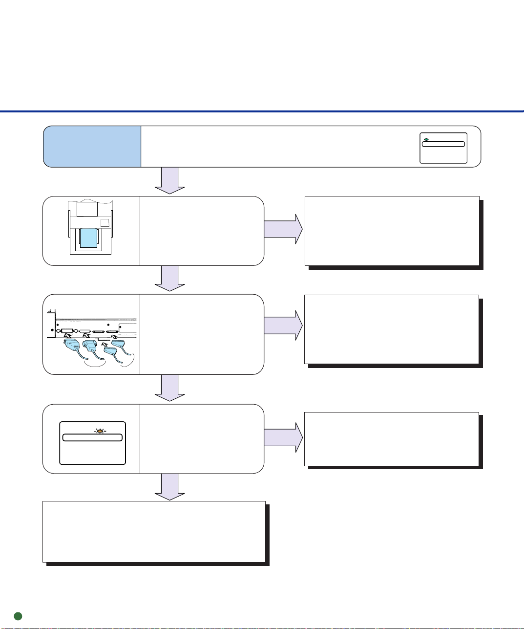
Initial Checks
If a problem occurs, check the following items before contacting a manufacturer’s authorized
service center.
Symptom1
Power cable
Power main switch
Power
switch
No power.
Is the power cable
connected correctly?
YES
Is the main line switch
on?
YES
Did you press the power
switch on the operator
panel ?
Operator panel
POWER
NO
Connect the power
cable correctly.
NO
Press the “I” side of the
main line switch.
NO
Press the power switch on
the operator panel.
YES
Contact a manufacturer’s authorized
service center.
5-5
Page 57
Symptom2
Read processing does not start.
Operator panel
POWER
Document
Interface cable
or
Operator panel
CHECK
Are the documents loaded
properly? (Straight edge,
no dogear, no bend
corners, staples)
YES
Is the interface cable
connected properly?
Or is the baud rate
correct?
(Video, RS-232C, or
SCSI interfaces)
YES
Does the CHECK lamp
blink?
NO
NO
Load the documents properly.
(See p1-5)
NO
Connect the interface cable
properly.
Or set the correct baud rate.
YES
Messages and Actions
(See p5-13)
5-6
Turn the power off and on to check if read
processing starts.
When read processing does not start, contact a
manufacturer’s authorized service center.
Page 58

Symptom3
Pictures and photographs are not read correctly.
Transport path
Lamp
Is “Photo” mode
selected?
YES
Is halftone or dithering
processing selected?
YES
Is there dirt or dust in
transport path?
YES
Is the lamp attached
correctly?
NO
NO
NO
NO
Select the “Photo” mode
(White level following off)
through the scanner setting
menu in the software.
Select a halftone or dithering
mode from the host
computer.
Clean the rollers, transport
path, glass and lamps.
(See Chapter 2)
Re-attach the lamp.
(See p2-14 to 2-17,
p3-2 to 3-5)
YES
Contact a manufacturer’s authorized
service center.
5-7
Page 59

Symptom4
Characters and lines are not read correctly.
Is “Line Art” mode
selected?
YES
Is there dirt or dust in
transport path?
Transport path
YES
Contact a manufacturer’s authorized
service center.
NO
Select “Line Art” mode from
the host computer.
NO
Clean the rollers, transport
path, glass, and lamps.
(See Chapter 2)
5-8
Page 60

Symptom5
Black stripes appear in the image of the display.
YES
Is the lamp surface
dirty?
Clean the lamp surface.
(See p2-14 to 2-17)
NO
Is the linedrawing mode
selected?
And does the text
appear on the first 3 mm
of the page?
YES
Select photo mode.
NO
YES
Is the lamp burned
out?
NO
Contact a manufacturer’s authorized
service center.
Replace the lamp.
(See p3-2 to 3-5)
5-9
Page 61

Symptom6
Action depends on the displayed message:
SF2 (SF3) did not detect leading (trailing)
edge of paper
Remove paper and clear the sensors.
Hopper empty
Set the document.
Cover open
Close the side cover.
Close the Endorser cover.
Mis-pick
Go to Symptom 7.
Pick roller unit not set
Set the pick roller unit.
Hopper overload
Reduce document stack in hopper.
The CHECK lamp blinks.
CHECK
Operator panel
Turn the power off once and
on again.
CHECK
Does the CHECK
lamp still blink?
YES
NO
5-10
End
Contact a manufacturer’s authorized
service center.
Page 62

Symptom7
Mis-pick or paper jam frequently occurs.
• Does the paper have
curled edges?
• Is the paper stack
uneven?
NO
Are pick rollers,
separation roller,
brake roller, pad or
paper path dirty?
NO
Are the pick roller unit
and brake roller in the
correct position?
NO
YES
YES
YES
Smooth out the curled paper
or reduce document stack in
hopper.
(See p1-5)
Clean the pick rollers,
separation roller, brake roller,
pad or paper path.
(See Chapter 2)
Mount the pick roller unit and
brake roller correctly.
(See p3-6 to 3-10)
Is the roller worn out?
(See Appendix)
NO
YES
Replace the roller.
5-11
Page 63

Contact a manufacturer’s authorized
service center.
5-12
Page 64

Messages and Actions
Operator panel
■ Device and Operator Actions for Temporary Errors
If a temporary error is detected in the scanner, (CHECK) lamp at the operator panel blinks.
SF2 (SF3) did not detect leading
(trailing) edge of peper
Hopper empty
Cover open
Mis-pick
Pick roller unit not set
Hopper overload
Open the upper transport unit and remove the document on the
*
transport path. Close the unit. Return the jammed or double-feed
document to the hopper and read it again.
Press the CANCEL button or issue the start command. Load
*
documents on the hopper and ENTER reading them.
Close the upper transport unit or the endorser cover. Or the side
cover.
Open the upper transport unit and remove the document on the
*
transport path. Close the unit. Return the jammed document on
the hopper and read it again.
Open the upper transport unit and correct the pick roller unit
*
setting. Close the upper transport unit. See “Pick Roller Unit
Replacement”.
*
Reduce document stack in the hopper.
*:Press
CANCEL
to reset these errors.
5-13
Page 65

■ Device and Operator Actions for Equipment Errors
If an equipment error is detected in the scanner, the (CHECK) lamp at the operator panel blinks.
Lamp Alarm: Front
Lamp Alarm: Back
Optical error: Front
Optical error: Back
Hopper over run
Paper feed error.
Clear paper path to continue
Hardware alarm
EEPROM alarm
Heater Alarm 1
Heater Alarm 2
Check if the lamp is attached correctly. Replace lamp
according to the replacement method. If turning the power on
again does not recover a scanner, contact a manufacturer’s
authorized service center.
Make sure that there is not anything on the hopper table or in
the transport path. If turning the power on again does not
recover a scanner, contact a manufacturer’s authorized
service center.
If turning the power on again does not recover the scanner,
contact a manufacturer’s authorized service center.
5-14
Page 66

Problem Checklist
Before contacting the manufacturer's authorized service center, please fill in the following items.
■ General
Model (Example) M4099D
Part number (Example) CA04315-B002
Serial number (Example) 100
Manufactured data (Example) 2000-02 (ex. Feb. 2000)
Version The version is printed on the version label located at the
Date of purchase
Symptoms
Persistent problem?
Serviced before (when and how)
■ Transport error
=
=
=
=
bottom right of the rear of the equipment. The version is
checked with the double line. This example is for A3 version.
Error message if any.
Type of document
What is your daily usage
Date of last cleaning.
Date of the consumable
replacement
■ Image error
Interface controller model
Software/application name
Can yhou send the original and
output of the sheet by facsimile?
5-15
Page 67

Appendix
Consumable counter
This scanner is equipped with an internal counter that can be used to monitor the life of
your consumable parts. It is recommended that the pick roller unit, brake roller, and pad
be replaced every 300,000 sheets or one year when scanning Xerox paper types. This
cycle will be shorter if scanning treated paper types such as carbonless paper types.
■ Setting the consumable counter
Press
“Ready”. The <<MODE SELECT>>
screen appears with SETUP blinking.
Press
screen appears (or Paper Length
Check).
Press
Consumable Counter screen appears.
Press
consumable counter is displayed in ten
thousands of sheets.
Press (↓) or (↑). The value
changes (001 to 256). Holding down
The recommended value is 030.
MENU
ENTER
ENTER
(↓) or (↑) speeds up the change.
when the LCD displays
twice. The Settings
(→)
eleven times. The
. The value of the
<<MODE SELECT>>
SETUP BROWSE
<<SETUP MODE>>
Settings
<<SETUP MODE>>
Consumable Counter
Consumable Counter
XXX 0000 sheets
Consumable Counter
XXX 0000 sheets
5-16
Page 68

When the desired value is displayed,
press
ENTER
to save the value. The
Consumable Counter screen appears.
<<SETUP MODE>>
Consumable Counter
Press
CANCEL
to the Ready screen.
twice. The LCD returns
Ready
■ Resetting the consumable counter
There is another case in which you may reset the consumable counter. If the scanner
detects a consumable life alarm which is displayed when the consumable counter
reaches the prescribed value, the LCD indicates an alarm that the consumable may be
expired. In this case, press
CANCEL
the counter after replacing the consumable.) The LCD indicates the following message:
Reset Consumable Counter?
Yes:Enter No:Cancel
Yes (Enter) : The scanner resets the consumable counter to zero.
No (Cancel) : The scanner does not reset the consumable counter. In this case,
the consumable life alarm recurs when the next sheet is fed.
to proceed the next operation (usually, you reset
5-17
Page 69

 Loading...