


 Loading...
Fujitsu M400A, M600, M200R, GP 7000F, M400R User Manual
...GP 7000F
M200, M200R, M400A, M400R, M600, M600R
Edition December 1999
Copyright and Trademarks
Copyright © Fujitsu Siemens Computers GmbH 1999.
All rights reserved.
Delivery subject to availability; right of technical modifications reserved.
All hardware and software names used are trademarks of their respective manufacturers.

1 Preface
This manual contains the operating instructions for the GranPower7000 (GP 7000F) system from Fujitsu Siemens Computers. A chapter about the connection of Siemens specific devices precedes the actual operating instructions.
U42335-J-Z775-1-76 |
1 |
2 Console connections to GP 7000F
This chapter describes connections to the M200, M200R, M400A, M400R, M600 and
M600R models of the Fujitsu Siemens Computers GP 7000F system with a view to attaching existing components of Siemens devices to Fujitsu equipment. Graphical or serial consoles can be connected.
! |
The GP 7000F systems do not support SIDATA |
(installation by customer is not allowed). |
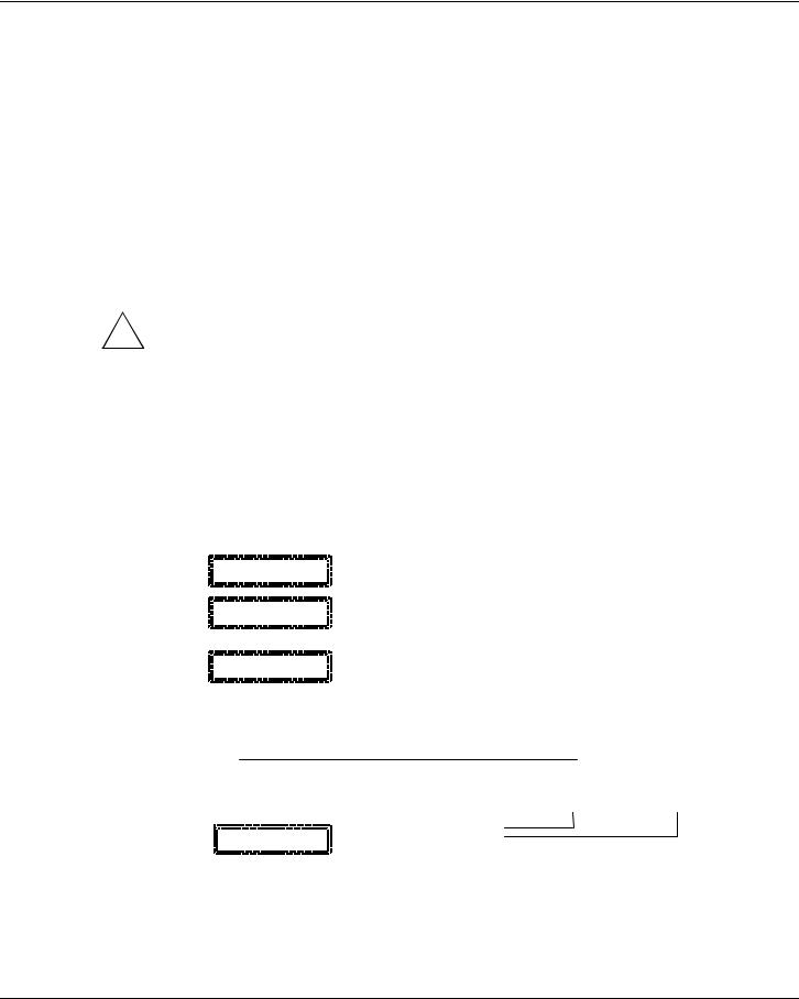
2.1 Graphical console
It is preferable to connect graphical consoles.
GP 7000F |
|
|
|
|
|
|
|
|
|
|
|
|
|
|
|
|
|
|
|
V.24 (A) |
|
|
|
|
|
|
|
|
|
|
|
||
system |
|
|
|
|
|
|
|
|
|
|
|
|
|
|
||
|
|
|
|
Teleservice |
|
|
|
|
|
|
|
|
|
|||
|
|
|
|
|
|
|
|
|
|
|
|
|
|
|
||
|
|
|
|
|
V.24 (B) |
|
|
|
|
|
|
|
|
|
||
|
|
|
|
|
preferably |
|
|
|
|
|
|
|
|
|
||
|
|
|
|
|
|
|
|
|
|
|
|
|
|
|
||
|
|
|
|
|
|
|
|
|
|
|
|
|
|
|
|
|
|
|
|
|
|
|
|
|
|
|
|
|
|
|
|
|
|
|
|
|
|
10/100 Mbit Eth |
|
|
|
|
|
|
|
|
|
|
|
|
|
|
|
|
|
|
|
|
|
|
|
|
|
|
|
|
|
|
|
|
|
|
|
|
|
|
|
|
|
|
|
|
|
|
|
|
|
|
|
|
|
|
|
|
|
|
|
|
|
|
|
|
|
|
|
|
|
|
|
|
|
|
Monitor |
|
|
|
||
|
PCI graphics |
|
|
|
|
|
|
|
|
|
|
|||||
|
|
|
|
|
|
|
|
|
|
|
|
|
|
|||
|
controller |
|
|
|
|
|
|
|
|
|
|
|
|
|
||
|
|
|
|
|
|
|
|
|
|
|
|
|
||||
|
D:GP70F-CC10 |
|
|
|
|
|
|
|
|
|
|
|
|
|
||
|
|
|
|
|
|
|
|
|
|
|
|
|
||||
|
(option) |
|
|
|
|
|
|
|
|
|
|
|
|
|
||
|
|
|
|
|
|
Keyboard |
|
|
Mouse |
|||||||
|
|
|
|
|
|
|
|
|
|
|
||||||
|
|
|
|
|
|
|
|
|||||||||
|
|
|
|
|
|
|
|
|
|
|
|
|
|
|
|
|
|
|
|
|
|
|
|
|
|
|
|
|
|
|
|
|
|
|
|
|
|
Keyboard/mouse |
|
SUNAdapt |
|
(Keyboard with trackball |
||||||||
|
|
|
|
|
|
|||||||||||
|
|
|
|
|
|
|
|
|
||||||||
|
|
|
|
|
|
|
|
|
|
|
in the 19" rack) |
|||||
|
|
|
|
|
|
|
|
|
|
|
|
|
|
|
|
|
U42335-J-Z775-1-76 |
3 |
Graphical console |
Console connections to GP 7000F |
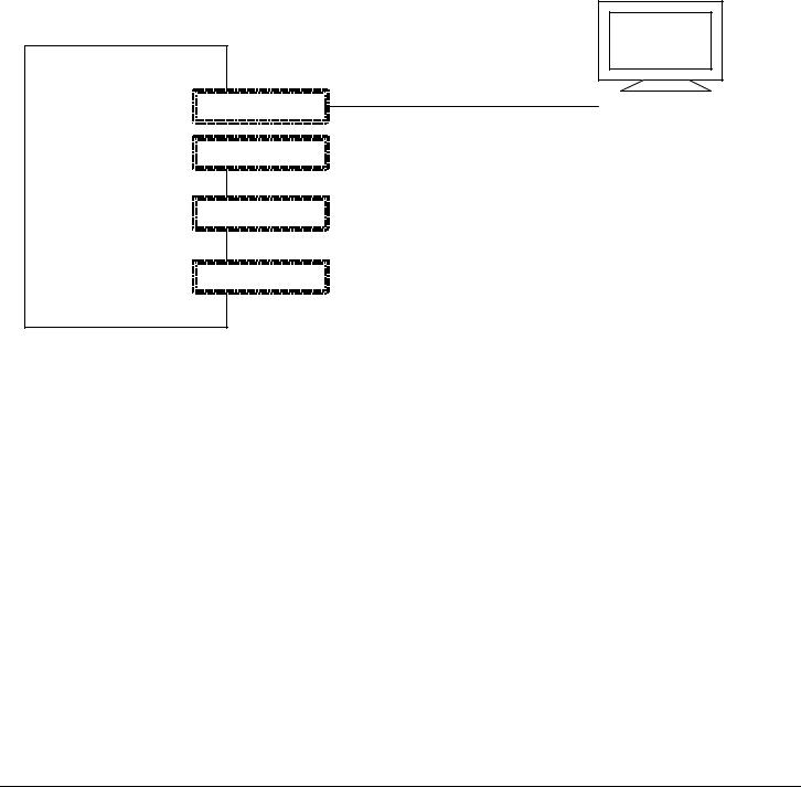
The following technical requirements must be met in order to connect graphical consoles:
–PCI graphics controller D:GP70F-CC10
The GP 7000F models can be made into a workstation or server with a graphical console by means of a PCI graphics card featuring a frame buffer.
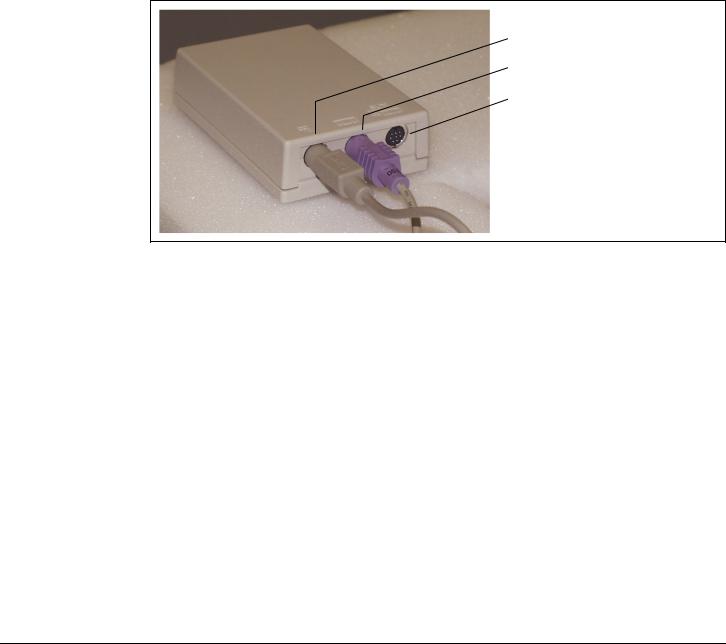
–An RM keyboard and mouse can be connected via the D:GP70F-AN10 interface converter. All models in the GP 7000F server family have a Sun-compatible keyboard/mouse interface. The adapter converts the interface signals to allow the keyboard and 3-button mouse featuring a PC-compatible interface to be connected to the server.
P S / 2 M a u s
PS/2 mouse
P S / 2 T a s t a t u r
PS/2 keyboard
S U N -
Sun keyboard/
T a s t a t u r / M a u s - mouse interface
S c h n it t s t e lle
Keyboard/mouse adapter
–Monitor (CRT or LCD)
–Keyboard
–Mouse
The same monitor, keyboard and mouse types have been released as for the Siemens systems.
4 |
U42335-J-Z775-1-76 |
Console connections to GP 7000F |
Serial console |
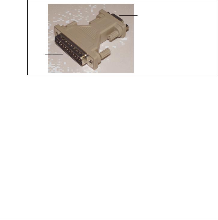
2.2 Serial console
A converter is used here to convert the 25-pin connector of the GP 7000F system to the usual 9-pin V.24/COM connector. This converter is preinstalled at the factory. A VT100 or VT200 emulation must be available for a serial console to be used.
V . 2 4 / C O M
9-pin
9 p o lig
D25s-pinu b
2 5 p o lig
25/9-pin converter
U42335-J-Z775-1-76 |
5 |
Serial console |
Console connections to GP 7000F |
2.2.1 LAN console
A Solaris PC is connected as a LAN console via an RCA (Remote Communication Adapter) attached to the V.24 console interface. Up to six servers can be attached to one RCA.
GP 7000F system
|
V.24 (A) |
|
|
|
RCA |
|
|
|
|||
|
|
|
|
|
|
|
|
|
|
|
|
LAN
V.24 (B)
console
|
|
|
|
|
|
|
|
|
10/100 Mbit Eth |
|
|
Ethernet hub |
|
|
|
|
|
|
|
|
|
|
|
|||
|
|
|
|
|
|
|
|
|
|
|
|
|
|
|
|
|
|
|
|
|
|
|
|
|
|
|
Teleservice
Keyboard/mouse
6 |
U42335-J-Z775-1-76 |
Console connections to GP 7000F |
Serial console |
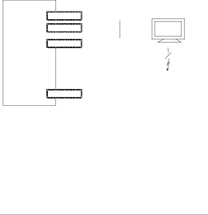
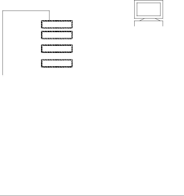
2.2.2Standard PC with terminal emulation
a)Windows 98 or NT (with NetTerm, for instance, but not with HyperTerminal)
b)LINUX (with Minicom or Seyon)
c)Solaris (cu)
GP 7000F system
PC
(NT, Windows)
|
V.24 (A) |
|
|
|
|
Teleservice |
|
|
|
|
|
|
V.24 (B) |
|
|
|
preferably |
|
|
|
|
|
10/100 Mbit Eth
Keyboard/mouse
U42335-J-Z775-1-76 |
7 |
Teleservice |
Console connections to GP 7000F |
2.2.3 TC20 or T100
Use of these terminals is intended as a migration solution only.
α console
GP 7000F
system |
|
|
V.24 (A) |
|
|
|
|
|
|
|
|
|
|
|
|
|
|||
|
|
|
|
Teleservice |
|||||
|
|
|
|
|
|
||||
|
|
|
|
V.24 (B) |
|||||
|
|
|
|
preferably |
|||||
|
|
|
|
|
|
||||
|
|
|
|
|
|
|
|
|
|
|
|
|
10/100 Mbit Eth |
|
|
|
|
||
|
|
|
|
|
|
|
|
|
|
|
|
|
|
|
|
|
|
|
|
|
|
|
Keyboard/mouse |
|
|
|
|
||
|
|
|
|
|
|
|
|
|
|
|
|
|
|
|
|
|
|
|
|
|
|
When operating with the LAN console, TC20 or T100 it is not possible to access the |
|||||||
|
i |
||||||||
|
Open Boot PROM using the BREAK signal. |
||||||||
2.3 Teleservice
The teleservice modem has to be connected via V.24 to the system board. The modem has to be ordered separately owing to national variants.
If a LAN console is used, connection of the modem is to the LAN console PC. Thus one teleservice port serves all connected servers.
8 |
U42335-J-Z775-1-76 |
P321-E102-02EN
USER'S MANUAL

IMPORTANT READING
FOR SAFE OPERATION
Handling of This Manual
This manual contains important information regarding the use and handling of this product. Read this manual thoroughly. Pay special attention to the section "Important Warnings". Use the product according to the instructions and information available in this manual.
FUJITSU makes every effort to prevent users and bystanders from being injured or from suffering from damages to their property. Use the product according to this manual.
IMPORTANT NOTE TO USERS
READ CAREFULLY ALL THROUGHOUT THIS MANUAL BEFORE USING THE PRODUCT. INCORRECT USE OF THE PRODUCT MAY CAUSE UNEXPECTED DAMAGE TO THE USERS OR BYSTANDERS.
While all efforts have been made to ensure the accuracy of all information in this manual, FUJITSU assumes no liability to any party for any damage caused by errors or omissions or by statement of any kind in this manual, its updates or supplements, whether such errors are omissions or statements resulting from negligence, accidents, or any other cause. FUJITSU further assumes no liability for incidental or consequential damages arising from the use of this manual. FUJITSU disclaims all warranties regarding the information contained herein, whether expressed, implied, or statutory.
DO NOT MAKE MECHANICAL OR ELECTRICAL MODIFICATIONS TO THE EQUIPMENT. FUJITSU LIMITED IS NOT RESPONSIBLE FOR REGULATORY COMPLIANCE OR SAFETY OF A MODIFIED FUJITSU PRODUCT.
DO NOT REPAIR OR INSTALL THE EQUIPMENT BY USERS. IT SHOULD BE PERFORMED BY A TRAINED SERVICE ENGINNER.
i
THIS PRODUCT IS NOT DESIGNED FOR USE IN ON-LINE CONTROL EQUIPMENT IN HAZARDOUS ENVIRONMENTS SUCH AS OPERATION OF NUCLEAR FACILITIES, AIRCRAFT NAVIGATION OR CONTROL, OR DIRECT LIFE SUPPORT MACHINES. HENCE, IF THESE PRODUCTS ARE USED IN SUCH HAZARDOUS ENVIRONMENTS, FUJITSU LIMITED AND SUN MICROSYSTEMS, INC. DOES NOT WARRANT THEM AT ALL.
FUJITSU reserves all the right to make changes to any products herein to improve reliability, function, or design, without further notice and without obligation.
FCC Class A Notice
This equipment has been tested and found to comply with the limits for a Class A digital device, pursuant to Part 15 of the FCC Rules. These limits are designed to provide reasonable protection against harmful interference when the equipment is operated in a commercial environment. This equipment generates, uses, and can radiate radio frequency energy and, if not installed and used in accordance with the instruction manual, may cause harmful interference to radio communications. Operation of this equipment in a residential area is likely to cause harmful interference in which case the user will be required to correct the interference at his own expense.
DOC Class A Notice
This class A digital apparatus meets all requirements of the Canadian Interference-Causing
Equipment Regulations.
Cet appareil numerique de la class A respecte toutes les exigences du Reglement sur le material brouiller du Canada.
Warning This is a Class A product of Electromagnetic Interference (EMI) standard. In a domestic environment this product may cause radio interference in which case the user may be required to take adequate measures.
VCCI/FCC label
The VCCI/FCC labels for models 200R, 400R, and the Expansion file unit (GP7B7FLxx) are affixed in the following locations:
 VCCI / FCC label
ii

 VCCI / FCC label
 VCCI / FCC label
Laser Radiation Statement (EU)
Class 1 Laser Product
TRADEMARK ACKNOWLEDGMENTS
All rights reserved. This product and related documentation are protected by copyright and distributed under licenses restricting its use, copying, distribution, and recompilation. No part of this product or related documentation may be reproduced in any form by any means without prior written authorization of Fujitsu Limited and its licensors, if any.
RESTRICTED RIGHTS LEGEND: Use, duplication, or disclosure by the United States Government is subject to the restrictions set forth in DFARS 252.227-7013 (c) (1) (ii) and FAR 52.227-19.
The product described in this book may be protected by one or more U.S. patents, foreign patents, or pending applications.
iii

TRADEMARKS
Fujitsu and the Fujitsu logo are trademarks of Fujitsu Limited.
SPARC64 is a registered trademark or trademark of SPARC International, Inc. in the United States and other countries used under license by Fujitsu Ltd. Products bearing SPARC64 trademarks comply with SPARC V9 architecture developed by SPARC International, Inc. Products bearing the SPARC trademarks are based on an architecture originally developed by Sun Microsystems, Inc. " Sun, the Sun logo, Sun Microsystems, Sun Microsystems Computer Corporation, the Sun Microsystems Computer Corporation logo, SunSoft, the SunSoft logo, Solaris, Solaris PEX, SunOS, SunLink, OpenWindows, Direct Xlib, SunSHIELD, NeWS, NeWSprint, SunInstall, DeskSet, ONC, ONC+, OpenBoot, Online DiskSuite, NFS, JumpStart, AnswerBook, the AnswerBook logo, SunDiag, ToolTalk, Sun PC, and Wabi are trademarks or registered trademarks of Sun Microsystems, Inc., in the U.S. and certain other countries.
UNIX is a registered trademark in the United States and other countries, licensed exclusively through X/Open Company Ltd.
All other product names mentioned herein are the trademarks of their respective owners.
THIS PUBLICATION IS PROVIDED "AS IS" WITHOUT WARRANTY OF ANY KIND, EITHER EXPRESS OR IMPLIED, INCLUDING, BUT NOT LIMITED TO, THE IMPLIED WARRANTIES OR MERCHANTABILITY, FITNESS FOR A PARTICULAR POURPOSE, OR NONINFRINGEMENT.
THIS PUBLICATION COULD INCLUDE TECHNICAL INACCURACIES OR TYPOGRAPHICAL ERRORS. CHANGES ARE PERIODICALLY ADDED TO THE INFORMATION HEREIN; THESE CHANGES WILL BE INCORPORATED IN NEW EDITIONS OF THE PUBLICATION. FUJITSU LIMITED MAY MAKE IMPROVEMENTS AND/OR CHANGES IN THE PRODUCT(S) AND/OR THE PROGRAM(S) DESCRIBED IN THIS PUBLICATION AT ANY TIME.
Documents produced by FUJITSU may contain technology controlled under the Foreign Exchange and Foreign Trade Control Law of Japan. The document which contains such technology should not be exported from Japan or transferred to anyone other than residents of Japan without first obtaining license from the Ministry of International Trade and Industry of Japan in accordance with the above law.
Second Edition: November 1999
This manual may be best printed on A4 size. If it is printed on 8.5" ( 11" size, adjust your printer setting in advance.
The contents of this manual may be revised without prior notice.
The contents of this manual shall not be disclosed in any way or reproduced in any media without the express written permission of Fujitsu Limited.
All Rights Reserved, Copyright (c) FUJITSU LIMITED 1999
iv

Preface
This manual explains the function, configuration, and operation of GP7000F. This manual is intended for the experienced users who have a basic knowledge of computer systems.
The structure of this manual is as follows:
Introduction to Chapters
CHAPTER 1 Product Outline
Chapter 1 describes the distinctive features of GP7000F.
CHAPTER 2 M200 Main Cabinet
Chapter 2 explains the device configuration and operation of M200 Main Cabinet.
CHAPTER 3 M200R Main Cabinet
Chapter 3 explains the device configuration and operation of M200R Main Cabinet.
CHAPTER 4 M400A Main Cabinet
Chapter 4 explains the device configuration and operation of M400A Main Cabinet.
CHAPTER 5 M400R Main Cabinet
Chapter 5 explains the device configuration and operation of M400R Main Cabinet.
CHAPTER 6 M600 Main Cabinet
Chapter 6 explains the device configuration and operation of M600 Main Cabinet.
CHAPTER 7 M600R Main Cabinet
Chapter 7 explains the device configuration and operation of M600R Main Cabinet.
CHAPTER 8 Expansion Disk Cabinet
Chapter 8 describes the distinctive features of the GP7000F external disk cabinet.
CHAPTER 9 Expansion File Unit Type-2(GP7B7FLxx)
Chapter 9 describes the distinctive features of the GP7000F rack mount expansion disk unit.
CHAPTER 10 Expansion File Unit(GP7B7FU1xx)
Chapter 10 describes the distinctive features of the GP7000F rack mount expansion disk unit.
CHAPTER 11 Input-Output Units
Chapter 11 explains the specifications of Input-Output units.
v

CHAPTER 12 External Interface
Chapter 12 explains the external interface of the main cabinet such as UPS Control Interface,
RS232C Interface, and Centronics Interface.
CHAPTER 13 RCI Setting
Chapter 13 explains the description of RCI commands to be used for managing nodes.
CHAPTER 14 Troubleshooting
Chapter 14 will help the user isolate the cause of system failures, and provides suggested solutions.
Conventions for Warning Messages
A warning message consists of a signal and statements. The signal consists of a symbol and a signal word or just a signal word.
The following are the signals and their meanings:

 CAUTION
This indicates a hazardous situation could result in minor or moderate personal injury if the user does not perform the procedure correctly. This signal also indicates that damage to the product or other property, may occur if the user does not perform the procedure correctly.
IMPORTANT
This indicates information that could help the user use the product more efficiently.
In the text, the signal is centered, followed below by the indented message. A wider line space precedes and follows the message to show where the message begins and ends. The following is an example:
(Example)
Data destruction: Do not press these buttons before installing the necessary
CAUTION
software package. Otherwise, data may be destroyed. Turn off the system in the OBP prompt state if the software package is not installed.
Attention
Please forward any comments you may have regarding this manual.
To make this manual easier for users to understand, opinions from readers are needed. Please write your opinions or requests on the "Comment Form" sheet at the back of this manual and forward it to the address provided on the sheet.
vi
vii

Important Warnings
The following are cautions found in this manual. They have been compiled here with corresponding page
references.
A hazardous situation could result in minor or moderate personal injury if the
CAUTION
user does not perform the procedure correctly. Also, damage to the product or other property may occur.
Task |
Warning |
|
|
Normal Operation |
Data destruction: Pressing the RESET switch while the |
|
system is running may destroy data. |
|
|
System Installation |
Be sure to install software packages from "Basic Software |
|
Extension" or "Enhanced Support Facility. Otherwise, above |
|
switch functions or proper messages on LCD panel are not |
|
guaranteed. |
|
|
Terminal break command |
If used improper commands at the ok prompt, the GP7000F |
|
may be destroyed. If you need to used any other commands |
|
except shown on this manual, you should well understand |
|
the function and usage of the command before using it. |
|
|
Power Off |
Be sure to eject backup tape media and any diskettes before |
|
power-off the system, if the media are installed. Other |
|
wise, the data on the media may be destroyed. |
|
|
Normal Operation |
Except in an emergency, never turn off the AC switch or |
|
disconnect the power cable wile the GP7000F main cabinet is |
|
turned on. If you do, data in the disk drive may be |
|
destroyed. |
|
|
viii
Task |
Warning |
|
|
System Installation |
Install "Basic Software Extension" or "Enhanced Support |
|
Facility"before operating the system. Without this package, |
|
incorrect front panel operations and hardware errors may cause |
|
the system to shutdown or destroy data. |
|
|
Disk Expansion Unit |
Be sure to replace the power supply fan when installing the |
Installation |
Disk Expansion Unit. Otherwise, the system will shutdown or |
|
disk units will deteriorate due to a temperature rise in the |
|
M200 main cabinet caused by insufficient cooling. |
|
|
Disk Expansion Unit |
If the installing location (slot) is not set or set |
Installation |
incorrectly, the disk drive may not be hot-swappable. |
|
Data may be destroyed as a result of inadvertently replacing |
|
the different disk drive. Be sure to set the installing |
|
location (slot) correctly. |
|
Also, while replacing or initializing NVRAM, set the |
|
installing location again. |
|
|
Normal Operation |
Do not set the AC main line switch to OFF, not disconnect |
|
the power cable or RCI cable while the GP7000F main cabinet |
|
is powered on, unless absolutely necessary. Otherwise, the |
|
data may be destroyed in the disk units. |
|
|
Normal Operation |
Do not set the AC main line switch to OFF, nor disconnect |
|
the power cable or RCI cable while the GP7000F main cabinet |
|
is powered on, unless absolutely necessary. Otherwise, the |
|
data in the disk units may be destroyed. |
|
|
Replacing Disk Drives |
When replacing the disk unit,take the following precautions. |
|
If these precautions are not observed, the disk unit or its |
|
data may be destroyed. |
|
|
Formatting Disk Drives |
Carefully proceed formatting a disk drive. Once formatting |
|
a disk drive, data on the disk never restored, if you don't |
|
have backup files. |
|
|
Handling Floppy Disks |
Do not eject a floppy disk while the access LED is on, other |
|
wise the floppy disk or the data on the diskette may be |
|
destroyed. |
|
For information on the handling method, see Table 11.2, |
|
"Handling floppy disks." |
|
|
Ejecting DAT cartridge |
Data destruction: Do not press the eject switch during an |
|
operation (when the tape LED is blinking). If the eject |
|
switch is held down for about 5 seconds or pressed 3 times |
|
within a 5 minutes period, the forced ejection function may |
|
execute and the data being written may be destroyed. |
|
|
Handling DAT cartridge |
When using the data cartridge (DAT), take the following |
|
precautions. If these precautions are not observed, the |
|
DAT unit or its data may be destroyed. |
|
|
Storing 8-mm cartridge |
When using or storing the data cartridge, take the following |
|
precautions. If these precautions are not taken, the data |
|
on 8-mm tape may be destroyed. |
|
|
Ejecting QIC cartridge |
Data destruction: Do not press the eject switch during an |
|
operation. The forced ejection function may operate and |
|
data being written may be destroyed. |
|
|
Storing QIC cartridge |
When using or storing the data cartridge, take the following |
|
precautions. If these precautions are not taken, the QIC |
|
tape unit or its data may be destroyed. |
|
|
ix
CONTENTS
|
|
|
|
|
|
|
|
CHAPTER 1 |
Product Outline |
1 |
|
|
1.1 |
Key Features |
2 |
|
1.2 |
Operator Panel |
5 |
|
1.3 |
External Interface |
8 |
|
1.4 |
Console |
10 |
|
1.5 |
Power On/Off |
11 |
|
1.6 |
Installation of Basic Software Extension or Enhanced Support Facility |
12 |
|
1.7 |
local-mac-address Property |
12 |
|
|
|
|
CHAPTER 2 |
M200 Main Cabinet |
13 |
|
|
2.1 |
Overview |
14 |
|
2.2 |
Device Configuration |
15 |
|
2.3 |
Systemboard |
19 |
|
2.4 |
Disk Units |
21 |
|
2.5 |
PCI Slots |
23 |
|
2.6 |
Installation |
23 |
|
|
|
|
i

CHAPTER 3 |
M200R Main Cabinet |
27 |
|
|
3.1 |
Overview |
28 |
|
3.2 |
Device Configuration |
29 |
|
3.3 |
Systemboard |
32 |
|
3.4 |
Disk Units |
34 |
|
3.5 |
PCI Slots |
35 |
|
3.6 |
Installation |
36 |
|
|
|
|
CHAPTER 4 |
M400A Main Cabinet |
41 |
|
|
4.1 |
Overview |
42 |
|
4.2 |
Device Configuration |
43 |
|
4.3 |
Systemboard |
46 |
|
4.4 |
Disk Units |
48 |
|
4.5 |
PCI Slots |
49 |
|
4.6 |
Installation |
50 |
|
|
|
|
CHAPTER 5 |
M400R Main Cabinet |
53 |
|
|
5.1 |
Overview |
54 |
|
5.2 |
Device Configuration |
55 |
|
5.3 |
Systemboard |
58 |
|
5.4 |
Disk Units |
60 |
|
5.5 |
PCI Slots |
61 |
|
5.6 |
Installation |
62 |
|
|
|
|
CHAPTER 6 |
M600 Main Cabinet |
67 |
|
|
6.1 |
Overview |
68 |
|
6.2 |
Device Configuration |
69 |
ii
|
|
|
|
CONTENTS |
|
|
|
6.3 |
Systemboard |
72 |
|
|
|
6.4 |
Disk Units |
75 |
|
|
|
6.5 |
PCI Slots |
75 |
|
|
|
6.6 |
Installation |
77 |
|
|
|
|
|
||
CHAPTER 7 |
M600R Main Cabinet |
81 |
|
||
|
|
7.1 |
Overview |
82 |
|
|
|
7.2 |
Device Configuration |
83 |
|
|
|
7.3 |
Systemboard |
86 |
|
|
|
7.4 |
Disk Units |
88 |
|
|
|
7.5 |
PCI Slots |
89 |
|
|
|
7.6 |
Installation |
91 |
|
|
|
|
|
||
CHAPTER 8 |
Expansion Disk Cabinet |
95 |
|
||
|
|
8.1 |
Product Outline |
96 |
|
|
|
8.2 |
Device Configuration |
97 |
|
|
|
8.3 |
Hot System Replacement |
101 |
|
|
|
8.4 |
Installation |
102 |
|
|
|
|
|
||
CHAPTER 9 |
Expansion File Unit Type-2 (GP7B7FLxx) |
105 |
|
||
|
|
9.1 |
Product Outline |
106 |
|
|
|
9.2 |
Device Configuration |
107 |
|
|
|
9.3 |
Hot System Replacement |
109 |
|
|
|
9.4 |
Installation |
110 |
|
|
|
|
|||
CHAPTER 10 Expansion File Unit (GP7B7FU1xx) |
113 |
|
|||
|
|
10.1 |
Product Outline |
114 |
|
iii

|
10.2 |
Device Configuration |
115 |
|
10.3 |
Hot System Replacement |
117 |
|
10.4 |
Installation |
118 |
|
|
|
|
CHAPTER 11 |
Input-Output Units |
121 |
|
|
11.1 |
Disk Units |
122 |
|
11.2 |
Floppy Disk Units |
123 |
|
11.3 |
CD-ROM Unit |
126 |
|
11.4 |
Tape Unit |
128 |
|
11.5 |
DAT Unit |
129 |
|
11.6 |
8-mm Tape Unit |
135 |
|
11.7 |
QIC Tape Unit |
140 |
|
|
|
|
CHAPTER 12 |
External Interfaces |
145 |
|
|
12.1 |
UPS Control Interface |
146 |
|
12.2 |
RS232C Interface |
148 |
|
12.3 |
Parallel Interface |
151 |
|
|
|
|
CHAPTER 13 |
RCI Setting |
153 |
|
|
13.1 |
Overview |
154 |
|
13.2 |
RCI Commands |
154 |
|
13.3 |
Liquid Crystal Display (LCD) Specifications |
155 |
|
|
|
|
CHAPTER 14 |
Troubleshooting |
157 |
|
|
14.1 |
Overview |
158 |
|
14.2 |
Commands at the ok prompt |
158 |
|
14.3 |
Initial Diagnosis Sequence |
159 |
iv

CONTENTS
14.4 SCF Error Messages |
160 |
v
ILLUSTRATIONS
|
|
|
|
|
|
|
|
|
Figure 1.1 |
Operator Panel (M200, M600) |
5 |
|
Figure 1.2 |
Operator Panel (M200R, M400A, M400R, M600R) |
5 |
|
Figure 2.1 |
Front View of M200 Main Cabinet |
14 |
|
Figure 2.2 |
Open View of M200 Main Cabinet |
16 |
|
Figure 2.3 |
Rear View of M200 Main Cabinet |
18 |
|
Figure 2.4 |
Systemboard Layout of M200 |
19 |
|
Figure 2.5 |
Disk Drive Bays of M200 Main Cabinet |
21 |
|
Figure 3.1 |
Front View of M200R Main Cabinet |
28 |
|
Figure 3.2 |
Open View of M200R Main Cabinet |
29 |
|
Figure 3.3 |
Rear View of M200R Main Cabinet |
31 |
|
Figure 3.4 |
Systemboard Layout of M200R |
32 |
|
Figure 4.1 |
Front View of M400A Main Cabinet |
42 |
|
Figure 4.2 |
Open View of M400A Main Cabinet |
43 |
|
Figure 4.3 |
Rear View of M400A Main Cabinet |
45 |
|
Figure 4.4 |
Systemboard Layout of M400A |
46 |
|
Figure 5.1 |
Front View of M400R Main Cabinet |
54 |
|
Figure 5.2 |
Open View of M400R Main Cabinet |
55 |
|
Figure 5.3 |
Rear View of M400R Main Cabinet |
57 |
|
Figure 5.4 |
Systemboard Layout of M400R |
58 |
|
Figure 6.1 |
Front View of M600 Main Cabinet |
68 |
vii

Figure 6.2 |
Open View of M600 Main Cabinet |
69 |
Figure 6.3 |
Rear View of M600 Main Cabinet |
71 |
Figure 6.4 |
Systemboard Layout of M600 |
72 |
Figure 6.5 |
PCI IO Board Layout of M600 |
75 |
Figure 7.1 |
Front View of M600R Main Cabinet |
82 |
Figure 7.2 |
Open View of M600R Main Cabinet |
83 |
Figure 7.3 |
Front View of M600R Main Cabinet (remove Front cover) |
84 |
Figure 7.4 |
Rear View of M600R Main Cabinet |
85 |
Figure 7.5 |
Systemboard Layout of M600R |
86 |
Figure 7.6 |
PCIBPR Board Layout of M600R |
89 |
Figure 7.7 |
PCIRSR Board Layout of M600R |
89 |
Figure 8.1 |
Front View of Expansion Disk Cabinet |
97 |
Figure 8.2 |
Drive Bays of Expansion Disk Cabinet |
98 |
Figure 8.3 |
Rear View of Expansion Disk Cabinet |
100 |
Figure 9.1 |
Front View of Expansion File Unit Type-2 |
106 |
Figure 9.2 |
Drive Bays of Expansion File Unit Type-2 |
107 |
Figure 9.3 |
Drive Bays of Expansion File Unit Type-2 |
108 |
Figure 9.4 |
Rear View of Expansion File Unit Type-2 |
108 |
Figure 10.1 |
Front View of Expansion File Unit |
114 |
Figure 10.2 |
Drive Bays of Expansion File Unit |
115 |
Figure 10.3 |
Rear View of Expansion File Unit |
116 |
Figure 11.1 |
Floppy Disk Unit Front Panel |
123 |
Figure 11.2 |
Inserting Floppy Disks |
124 |
Figure 11.3 |
CD-ROM Unit Front Panel |
126 |
Figure 11.4 |
Mark on CD-ROM Disk |
127 |
Figure 11.5 |
DAT Unit Front Panel |
130 |
Figure 11.6 |
DDS Logos |
132 |
Figure 11.7 |
DDS Media Recognition System Logo |
132 |
Figure 11.8 |
Inserting a Data Cartridge in The DAT Unit |
132 |
Figure 11.9 |
DAT Data Cartridge Write-protection Tab |
133 |
Figure 11.10 |
8-mm Tape Unit Front Panel |
136 |
Figure 11.11 |
8-mm Tape Data Cartridge |
137 |
Figure 11.12 |
Cleaning Cartridge of The 8-mm Tape Unit |
139 |
Figure 11.13 |
Cleaning Cartridge of The 8-mm Tape Unit |
139 |
Figure 11.14 |
QIC Tape Drive Front Panel |
140 |
Figure 11.15 |
QIC Data Cartridge |
142 |
viii
Loading...