

Page 1
Page 2

Page 3

SPARC Enterprise
™
M4000/M5000 Servers
Service Manual
Manual Code C120-E352-06EN
Part No. 819-7903-13
August 2009, Revision A
Page 4

Copyright 2007-2009 Sun Microsystems, Inc., 4150 Network Circle, Santa Clara, California 95054, U.S.A. All rights reserved.
FUJITSU LIMITED provided technical input and review on portions of this material.
Sun Microsystems, Inc. and Fujitsu Limited each own or control intellectual property rights relating to products and technology described in
this document, and such products, technology and this document are protected by copyright laws, patents and other intellectual property laws
and international treaties. The intellectual property rights of Sun Microsystems, Inc. and Fujitsu Limited in such products, technology and this
document include, without limitation, one or more of the United States patents listed at http://www.sun.com/patents and one or more
additional patents or patent applications in the United States or other countries.
This document and the product and technology to which it pertains are distributed under licenses restricting their use, copying, distribution,
and decompilation. No part of such product or technology, or of this document, may be reproduced in any form by any means without prior
written authorization of Fujitsu Limited and Sun Microsystems, Inc., and their applicable licensors, if any. The furnishing of this document to
you does not give you any rights or licenses, express or implied, with respect to the product or technology to which it pertains, and this
document does not contain or represent any commitment of any kind on the part of Fujitsu Limited or Sun Microsystems, Inc., or any affiliate of
either of them.
This document and the product and technology described in this document may incorporate third-party intellectual property copyrighted by
and/or licensed from suppliers to Fujitsu Limited and/or Sun Microsystems, Inc., including software and font technology.
Per the terms of the GPL or LGPL, a copy of the source code governed by the GPL or LGPL, as applicable, is available upon request by the End
User. Please contact Fujitsu Limited or Sun Microsystems, Inc.
This distribution may include materials developed by third parties.
Parts of the product may be derived from Berkeley BSD systems, licensed from the University of California. UNIX is a registered trademark
in the U.S. and in other countries, exclusively licensed through X/Open Company, Ltd.
Sun, Sun Microsystems, the Sun logo, Java, Netra, Solaris, Sun Ray, Answerbook2, docs.sun.com, OpenBoot, and Sun Fire are trademarks or
registered trademarks of Sun Microsystems, Inc., or its subsidiaries, in the U.S. and other countries.
Fujitsu and the Fujitsu logo are registered trademarks of Fujitsu Limited.
All SPARC trademarks are used under license and are registered trademarks of SPARC International, Inc. in the U.S. and other countries.
Products bearing SPARC trademarks are based upon architecture developed by Sun Microsystems, Inc.
SPARC64 is a trademark of SPARC International, Inc., used under license by Fujitsu Microelectronics, Inc. and Fujitsu Limited.
The OPEN LOOK and Sun™ Graphical User Interface was developed by Sun Microsystems, Inc. for its users and licensees. Sun acknowledges
the pioneering efforts of Xerox in researching and developing the concept of visual or graphical user interfaces for the computer industry. Sun
holds a non-exclusive license from Xerox to the Xerox Graphical User Interface, which license also covers Sun’s licensees who implement OPEN
LOOK GUIs and otherwise comply with Sun’s written license agreements.
United States Government Rights - Commercial use. U.S. Government users are subject to the standard government user license agreements of
Sun Microsystems, Inc. and Fujitsu Limited and the applicable provisions of the FAR and its supplements.
Disclaimer: The only warranties granted by Fujitsu Limited, Sun Microsystems, Inc. or any affiliate of either of them in connection with this
document or any product or technology described herein are those expressly set forth in the license agreement pursuant to which the product
or technology is provided. EXCEPT AS EXPRESSLY SET FORTH IN SUCH AGREEMENT, FUJITSU LIMITED, SUN MICROSYSTEMS, INC.
AND THEIR AFFILIATES MAKE NO REPRESENTATIONS OR WARRANTIES OF ANY KIND (EXPRESS OR IMPLIED) REGARDING SUCH
PRODUCT OR TECHNOLOGY OR THIS DOCUMENT, WHICH ARE ALL PROVIDED AS IS, AND ALL EXPRESS OR IMPLIED
CONDITIONS, REPRESENTATIONS AND WARRANTIES, INCLUDING WITHOUT LIMITATION ANY IMPLIED WARRANTY OF
MERCHANTABILITY, FITNESS FOR A PARTICULAR PURPOSE OR NON-INFRINGEMENT, ARE DISCLAIMED, EXCEPT TO THE
EXTENT THAT SUCH DISCLAIMERS ARE HELD TO BE LEGALLY INVALID. Unless otherwise expressly set forth in such agreement, to the
extent allowed by applicable law, in no event shall Fujitsu Limited, Sun Microsystems, Inc. or any of their affiliates have any liability to any
third party under any legal theory for any loss of revenues or profits, loss of use or data, or business interruptions, or for any indirect, special,
incidental or consequential damages, even if advised of the possibility of such damages.
DOCUMENTATION IS PROVIDED “AS IS” AND ALL EXPRESS OR IMPLIED CONDITIONS, REPRESENTATIONS AND WARRANTIES,
INCLUDING ANY IMPLIED WARRANTY OF MERCHANTABILITY, FITNESS FOR A PARTICULAR PURPOSE OR NON-INFRINGEMENT,
ARE DISCLAIMED, EXCEPT TO THE EXTENT THAT SUCH DISCLAIMERS ARE HELD TO BE LEGALLY INVALID.
Please
Recycle
Page 5

Copyright 2007-2009 Sun Microsystems, Inc., 4150 Network Circle, Santa Clara, California 95054, Etats-Unis. Tous droits réservés.
Entrée et revue tecnical fournies par FUJITSU LIMITED sur des parties de ce matériel.
Sun Microsystems, Inc. et Fujitsu Limited détiennent et contrôlent toutes deux des droits de propriété intellectuelle relatifs aux produits et
technologies décrits dans ce document. De même, ces produits, technologies et ce document sont protégés par des lois sur le copyright, des
brevets, d’autres lois sur la propriété intellectuelle et des traités internationaux. Les droits de propriété intellectuelle de Sun Microsystems, Inc.
et Fujitsu Limited concernant ces produits, ces technologies et ce document comprennent, sans que cette liste soit exhaustive, un ou plusieurs
des brevets déposés aux États-Unis et indiqués à l’adresse http://www.sun.com/patents de même qu’un ou plusieurs brevets ou applications
brevetées supplémentaires aux États-Unis et dans d’autres pays.
Ce document, le produit et les technologies afférents sont exclusivement distribués avec des licences qui en restreignent l’utilisation, la copie,
la distribution et la décompilation. Aucune partie de ce produit, de ces technologies ou de ce document ne peut être reproduite sous quelque
forme que ce soit, par quelque moyen que ce soit, sans l’autorisation écrite préalable de Fujitsu Limited et de Sun Microsystems, Inc., et de leurs
éventuels bailleurs de licence. Ce document, bien qu’il vous ait été fourni, ne vous confère aucun droit et aucune licence, expresses ou tacites,
concernant le produit ou la technologie auxquels il se rapporte. Par ailleurs, il ne contient ni ne représente aucun engagement, de quelque type
que ce soit, de la part de Fujitsu Limited ou de Sun Microsystems, Inc., ou des sociétés affiliées.
Ce document, et le produit et les technologies qu’il décrit, peuvent inclure des droits de propriété intellectuelle de parties tierces protégés par
copyright et/ou cédés sous licence par des fournisseurs à Fujitsu Limited et/ou Sun Microsystems, Inc., y compris des logiciels et des
technologies relatives aux polices de caractères.
Par limites du GPL ou du LGPL, une copie du code source régi par le GPL ou LGPL, comme applicable, est sur demande vers la fin utilsateur
disponible; veuillez contacter Fujitsu Limted ou Sun Microsystems, Inc.
Cette distribution peut comprendre des composants développés par des tierces parties.
Des parties de ce produit pourront être dérivées des systèmes Berkeley BSD licenciés par l’Université de Californie. UNIX est une marque
déposée aux Etats-Unis et dans d’autres pays et licenciée exclusivement par X/Open Company, Ltd.
Sun, Sun Microsystems, le logo Sun, Java, Netra, Solaris, Sun Ray, Answerbook2, docs.sun.com, OpenBoot, et Sun Fire sont des marques de
fabrique ou des marques déposées de Sun Microsystems, Inc., ou ses filiales, aux Etats-Unis et dans d’autres pays.
Fujitsu et le logo Fujitsu sont des marques déposées de Fujitsu Limited.
Toutes les marques SPARC sont utilisées sous licence et sont des marques de fabrique ou des marques déposées de SPARC International, Inc.
aux Etats-Unis et dans d’autres pays. Les produits portant les marques SPARC sont basés sur une architecture développée par Sun
Microsystems, Inc.
SPARC64 est une marques déposée de SPARC International, Inc., utilisée sous le permis par Fujitsu Microelectronics, Inc. et Fujitsu Limited.
L’interface d’utilisation graphique OPEN LOOK et Sun™ a été développée par Sun Microsystems, Inc. pour ses utilisateurs et licenciés. Sun
reconnaît les efforts de pionniers de Xerox pour la recherche et le développement du concept des interfaces d’utilisation visuelle ou graphique
pour l’industrie de l’informatique. Sun détient une license non exclusive de Xerox sur l’interface d’utilisation graphique Xerox, cette licence
couvrant également les licenciés de Sun qui mettent en place l’interface d’utilisation graphique OPEN LOOK et qui, en outre, se conforment
aux licences écrites de Sun.
Droits du gouvernement américain - logiciel commercial. Les utilisateurs du gouvernement américain sont soumis aux contrats de licence
standard de Sun Microsystems, Inc. et de Fujitsu Limited ainsi qu’aux clauses applicables stipulées dans le FAR et ses suppléments.
Avis de non-responsabilité: les seules garanties octroyées par Fujitsu Limited, Sun Microsystems, Inc. ou toute société affiliée de l’une ou l’autre
entité en rapport avec ce document ou tout produit ou toute technologie décrit(e) dans les présentes correspondent aux garanties expressément
stipulées dans le contrat de licence régissant le produit ou la technologie fourni(e). SAUF MENTION CONTRAIRE EXPRESSÉMENT
STIPULÉE DANS CE CONTRAT, FUJITSU LIMITED, SUN MICROSYSTEMS, INC. ET LES SOCIÉTÉS AFFILIÉES REJETTENT TOUTE
REPRÉSENTATION OU TOUTE GARANTIE, QUELLE QU’EN SOIT LA NATURE (EXPRESSE OU IMPLICITE) CONCERNANT CE
PRODUIT, CETTE TECHNOLOGIE OU CE DOCUMENT, LESQUELS SONT FOURNIS EN L’ÉTAT. EN OUTRE, TOUTES LES CONDITIONS,
REPRÉSENTATIONS ET GARANTIES EXPRESSES OU TACITES, Y COMPRIS NOTAMMENT TOUTE GARANTIE IMPLICITE RELATIVE À
LA QUALITÉ MARCHANDE, À L’APTITUDE À UNE UTILISATION PARTICULIÈRE OU À L’ABSENCE DE CONTREFAÇON, SONT
EXCLUES, DANS LA MESURE AUTORISÉE PAR LA LOI APPLICABLE. Sauf mention contraire expressément stipulée dans ce contrat, dans
la mesure autorisée par la loi applicable, en aucun cas Fujitsu Limited, Sun Microsystems, Inc. ou l’une de leurs filiales ne sauraient être tenues
responsables envers une quelconque partie tierce, sous quelque théorie juridique que ce soit, de tout manque à gagner ou de perte de profit,
de problèmes d’utilisation ou de perte de données, ou d’interruptions d’activités, ou de tout dommage indirect, spécial, secondaire ou
consécutif, même si ces entités ont été préalablement informées d’une telle éventualité.
LA DOCUMENTATION EST FOURNIE “EN L’ETAT” ET TOUTES AUTRES CONDITIONS, DECLARATIONS ET GARANTIES EXPRESSES
OU TACITES SONT FORMELLEMENT EXCLUES, DANS LA MESURE AUTORISEE PAR LA LOI APPLICABLE, Y COMPRIS NOTAMMENT
TOUTE GARANTIE IMPLICITE RELATIVE A LA QUALITE MARCHANDE, A L’APTITUDE A UNE UTILISATION PARTICULIERE OU A
L’ABSENCE DE CONTREFACON.
Page 6

Page 7

Contents
Preface xvii
1. Safety and Tools 1–1
1.1 Safety Precautions 1–1
1.2 System Precautions 1–2
1.2.1 Electrical Safety Precautions 1–2
1.2.2 Equipment Rack Safety Precautions 1–2
1.2.3 Filler Boards and Filler Panels 1–3
1.2.4 Handling Components 1–3
2. Fault Isolation 2–1
2.1 Determining Which Diagnostics Tools to Use 2–1
2.2 Checking the Server and System Configuration 2–4
2.2.1 Checking the Hardware Configuration and FRU Status 2–4
2.2.1.1 Checking the Hardware Configuration 2–5
2.2.2 Checking the Software and Firmware Configuration 2–6
2.2.2.1 Checking the Software Configuration 2–7
2.2.2.2 Checking the Firmware Configuration 2–7
2.2.3 Downloading the Error Log Information 2–8
2.3 Operator Panel 2–9
v
Page 8

2.4 Error Conditions 2–14
2.4.1 Predictive Self-Healing Tools 2–14
2.4.2 Monitoring Output 2–17
2.4.3 Messaging Output 2–17
2.5 LED Functions 2–18
2.6 Using the Diagnostic Commands 2–21
2.6.1 Using the showlogs Command 2–21
2.6.2 Using the fmdump Command 2–22
2.6.2.1 fmdump -V Command 2–22
2.6.2.2 fmdump -e Command 2–23
2.6.3 Using the fmadm faulty Command 2–23
2.6.3.1 fmadm repair Command 2–23
2.6.3.2 fmadm config Command 2–24
2.6.4 Using the fmstat Command 2–24
2.7 Traditional Solaris Diagnostic Commands 2–26
2.7.1 Using the iostat Command 2–27
2.7.1.1 Options 2–27
2.7.2 Using the prtdiag Command 2–28
2.7.2.1 Options 2–28
2.7.3 Using the prtconf Command 2–30
2.7.3.1 Options 2–30
2.7.4 Using the netstat Command 2–32
2.7.4.1 Options 2–33
2.7.5 Using the ping Command 2–34
2.7.5.1 Options 2–34
2.7.6 Using the ps Command 2–35
2.7.6.1 Options 2–35
2.7.7 Using the prstat Command 2–36
vi SPARC Enterprise M4000/M5000 Servers Service Manual • August 2009
Page 9

2.7.7.1 Options 2–36
2.8 Other Issues 2–37
2.8.1 Can’t Locate Boot Device 2–37
3. Periodic Maintenance 3–1
3.1 Tape Drive Unit 3–1
3.1.1 Cleaning the Tape Drive Unit 3–1
4. FRU Replacement Preparation 4–1
4.1 FRU Replacement Method 4–1
4.2 Active Replacement 4–4
4.2.1 Removing a FRU From a Domain 4–4
4.2.2 Removing and Replacing a FRU 4–5
4.2.3 Adding a FRU Into a Domain 4–5
4.2.4 Verifying Hardware Operation 4–6
4.3 Hot Replacement 4–6
4.3.1 Removing and Replacing a FRU 4–7
4.3.2 Verifying Hardware Operation 4–9
4.4 Cold Replacement (Powering the Server Off and On) 4–12
4.4.1 Powering the Server Off Using Software 4–12
4.4.2 Powering the Server On Using Software 4–13
4.4.3 Powering the Server Off Manually 4–14
4.4.4 Powering the Server On Manually 4–14
4.4.5 Verifying Hardware Operation 4–15
5. Internal Components Access 5–1
5.1 Sliding the Server In and Out to the Fan Stop 5–1
5.1.1 Sliding the Server Out of the Equipment Rack 5–2
5.1.2 Sliding the Server Into the Equipment Rack 5–4
5.2 Top Cover Remove and Replace 5–5
Contents vii
Page 10

5.2.1 Removing the Top Cover 5–5
5.2.2 Replacing the Top Cover 5–8
5.3 Fan Cover Remove and Replace 5–8
5.3.1 Removing the Fan Cover 5–8
5.3.2 Replacing the Fan Cover 5–10
6. Storage Devices Replacement 6–1
6.1 Hard Disk Drive Replacement 6–1
6.1.1 Accessing the Hard Disk Drive 6–4
6.1.2 Removing the Hard Disk Drive 6–4
6.1.3 Installing the Hard Disk Drive 6–5
6.1.4 Securing the Server 6–5
6.1.5 Accessing the Hard Disk Drive Backplane of the SPARC Enterprise
M4000 Server 6–6
6.1.6 Removing the Hard Disk Drive Backplane of the SPARC Enterprise
M4000 Server 6–6
6.1.7 Installing the Hard Disk Drive Backplane of the SPARC Enterprise
M4000 Server 6–7
6.1.8 Securing the Server 6–8
6.1.9 Accessing the Hard Disk Drive Backplane of the SPARC Enterprise
M5000 Server 6–9
6.1.10 Removing the Hard Disk Drive Backplane of the SPARC Enterprise
M5000 Server 6–10
6.1.11 Installing the Hard Disk Drive Backplane of the SPARC Enterprise
M5000 Server 6–10
6.1.12 Securing the Server 6–11
6.2 CD-RW/DVD-RW Drive Unit (DVDU) Replacement 6–12
6.2.1 Accessing the CD-RW/DVD-RW Drive Unit 6–15
6.2.2 Removing the CD-RW/DVD-RW Drive Unit 6–15
6.2.3 Installing the CD-RW/DVD-RW Drive Unit 6–16
6.2.4 Securing the Server 6–16
viii SPARC Enterprise M4000/M5000 Servers Service Manual • August 2009
Page 11

6.2.5 Accessing the CD-RW/DVD-RW Drive Backplane of the SPARC
Enterprise M4000 Server 6–17
6.2.6 Removing the CD-RW/DVD-RW Drive Backplane of the SPARC
Enterprise M4000 Server 6–17
6.2.7 Installing the CD-RW/DVD-RW Drive Backplane of the SPARC
Enterprise M4000 Server 6–18
6.2.8 Securing the Server 6–18
6.2.9 Accessing the CD-RW/DVD-RW Drive Backplane of the SPARC
Enterprise M5000 Server 6–19
6.2.10 Removing the CD-RW/DVD-RW Drive Backplane of the SPARC
Enterprise M5000 Server 6–20
6.2.11 Installing the CD-RW/DVD-RW Drive Backplane of the SPARC
Enterprise M5000 Server 6–20
6.2.12 Securing the Server 6–21
6.3 Tape Drive Unit Replacement 6–22
6.3.1 Accessing the Tape Drive Unit 6–25
6.3.2 Removing the Tape Drive Unit 6–25
6.3.3 Installing the Tape Drive Unit 6–26
6.3.4 Securing the Server 6–26
6.3.5 Accessing the Tape Drive Backplane of the SPARC Enterprise
M4000 Server 6–27
6.3.6 Removing the Tape Drive Backplane of the SPARC Enterprise
M4000 Server 6–28
6.3.7 Installing the Tape Drive Backplane of the SPARC Enterprise
M4000 Server 6–28
6.3.8 Securing the Server 6–29
6.3.9 Accessing the Tape Drive Backplane of the SPARC Enterprise
M5000 Server 6–30
6.3.10 Removing the Tape Drive Backplane of the SPARC Enterprise
M5000 Server 6–31
6.3.11 Installing the Tape Drive Backplane of the SPARC Enterprise
M5000 Server 6–31
6.3.12 Securing the Server 6–32
Contents ix
Page 12

7. Power Systems Replacement 7–1
7.1 Power Supply Unit Replacement 7–1
7.1.1 Accessing the Power Supply Unit 7–4
7.1.2 Removing the Power Supply Unit 7–4
7.1.3 Installing the Power Supply Unit 7–5
7.1.4 Securing the Server 7–5
8. I/O Unit Replacement 8–1
8.1 PCI Cassette Replacement 8–4
8.1.1 Accessing the PCI Cassette 8–5
8.1.2 Removing the PCI Cassette 8–5
8.1.3 Installing the PCI Cassette 8–6
8.1.4 Securing the Server 8–7
8.2 PCI Card Replacement 8–7
8.2.1 Removing the PCI Card 8–7
8.2.2 Installing the PCI Card 8–8
8.3 I/O Unit Replacement 8–10
8.3.1 Accessing the I/O Unit 8–10
8.3.2 Removing the I/O Unit 8–10
8.3.3 Installing the I/O Unit 8–11
8.3.4 Securing the Server 8–12
8.4 I/O Unit DC-DC Converter Replacement 8–12
8.4.1 Accessing the I/O Unit DC-DC Converter (DDC_A#0 or
DDC_B#0) 8–14
8.4.2 Removing the I/O Unit DC-DC Converter (DDC_A #0 or DDC_B
#0) 8–14
8.4.3 Installing the I/O Unit DC-DC Converter (DDC_A #0 or DDC_B
#0) 8–17
8.4.4 Securing the Server 8–21
8.4.5 Accessing the I/O Unit DC-DC Converter Riser 8–21
x SPARC Enterprise M4000/M5000 Servers Service Manual • August 2009
Page 13

8.4.6 Removing the I/O Unit DC-DC Converter Riser 8–22
8.4.7 Replacing the I/O Unit DC-DC Converter Riser 8–24
8.4.8 Securing the Server 8–24
9. XSCF Unit Replacement 9–1
9.1 XSCF Unit Replacement 9–1
9.1.1 Accessing the XSCF Unit 9–3
9.1.2 Removing the XSCF Unit 9–4
9.1.3 Installing the XSCF Unit 9–5
9.1.4 Securing the Server 9–5
10. Fan Modules Replacement 10–1
10.1 Fan Module Replacement 10–1
10.1.1 Accessing the 60-mm Fan Module 10–4
10.1.2 Removing the 60-mm Fan Module 10–5
10.1.3 Installing the 60-mm Fan Module 10–6
10.1.4 Securing the Server 10–6
10.1.5 Accessing the 172-mm Fan Module 10–7
10.1.6 Removing the 172-mm Fan Module 10–8
10.1.7 Installing the 172-mm Fan Module 10–9
10.1.8 Securing the Server 10–9
10.1.9 Accessing the 60-mm Fan Backplane 10–10
10.1.10 Removing the 60-mm Fan Backplane 10–11
10.1.11 Installing the 60-mm Fan Backplane 10–12
10.1.12 Securing the Server 10–12
10.1.13 Accessing the SPARC Enterprise M4000 172-mm Fan Backplane
10–13
10.1.14 Removing the SPARC Enterprise M4000 172-mm Fan Backplane
10–13
Contents xi
Page 14

10.1.15 Installing the SPARC Enterprise M4000 172-mm Fan Backplane
10–16
10.1.16 Securing the Server 10–16
10.1.17 Accessing the SPARC Enterprise M5000 172-mm Fan Backplane
10–17
10.1.18 Removing the SPARC Enterprise M5000 172-mm Fan Backplane
10–17
10.1.19 Installing the SPARC Enterprise M5000 172-mm Fan Backplane
10–20
10.1.20 Securing the Server 10–20
11. Memory Board Replacement 11–1
11.1 Memory Board Replacement 11–1
11.1.1 Accessing the Memory Board 11–5
11.1.2 Removing the Memory Board 11–6
11.1.3 Installing the Memory Board 11–7
11.1.4 Securing the Server 11–7
11.2 DIMM Replacement 11–8
11.2.1 Confirmation of DIMM Information 11–9
11.2.2 Memory Installation Configuration Rules 11–10
11.2.3 Installing Memory: 11–11
11.2.4 Accessing the DIMMs 11–11
11.2.5 Removing the DIMMs 11–12
11.2.6 Installing the DIMMs 11–13
11.2.7 Securing the Server 11–13
12. CPU Module Replacement 12–1
12.1 CPU Module Replacement 12–1
12.1.1 Accessing the CPU Module 12–4
12.1.2 Removing the CPU Module 12–5
12.1.3 Installing the CPU Module 12–6
xii SPARC Enterprise M4000/M5000 Servers Service Manual • August 2009
Page 15

12.1.4 Securing the Server 12–6
12.2 CPU Upgrade 12–7
12.2.1 SPARC64 VII CPU Modules Added to a New Domain 12–8
12.2.2 SPARC64 VII Processors Added to an Existing Domain 12–11
13. Motherboard Unit Replacement 13–1
13.1 Motherboard Unit Replacement 13–1
13.1.1 Accessing the SPARC Enterprise M4000 Motherboard Unit 13–4
13.1.2 Removing the SPARC Enterprise M4000 Motherboard Unit 13–5
13.1.3 Installing the SPARC Enterprise M4000 Motherboard Unit 13–6
13.1.4 Securing the Server 13–6
13.1.5 Accessing the SPARC Enterprise M5000 Motherboard Unit 13–7
13.1.6 Removing the SPARC Enterprise M5000 Motherboard Unit 13–8
13.1.7 Installing the SPARC Enterprise M5000 Motherboard Unit 13–10
13.1.8 Securing the Server 13–11
13.2 DC-DC Converter Replacement 13–12
13.2.1 Accessing the SPARC Enterprise M4000 DC-DC Converter 13–14
13.2.2 Removing the SPARC Enterprise M4000 DC-DC Converter 13–15
13.2.3 Installing the SPARC Enterprise M4000 DC-DC Converter 13–16
13.2.4 Securing the Server 13–16
13.2.5 Accessing the SPARC Enterprise M5000 DC-DC Converter 13–17
13.2.6 Removing the SPARC Enterprise M5000 DC-DC Converter 13–18
13.2.7 Installing the SPARC Enterprise M5000 DC-DC Converter 13–18
13.2.8 Securing the Server 13–18
14. Backplane Unit Replacement 14–1
14.1 Backplane Unit Replacement 14–1
14.1.1 Accessing the SPARC Enterprise M4000 Backplane Unit 14–4
14.1.2 Removing the SPARC Enterprise M4000 Backplane Unit 14–5
Contents xiii
Page 16

14.1.3 Installing the SPARC Enterprise M4000 Backplane Unit 14–7
14.1.4 Securing the Server 14–8
14.1.5 Accessing the SPARC Enterprise M5000 Backplane Unit 14–9
14.1.6 Removing the SPARC Enterprise M5000 Backplane Unit 14–10
14.1.7 Installing the SPARC Enterprise M5000 Backplane Unit 14–12
14.1.8 Securing the Server 14–12
15. Operator Panel Replacement 15–1
15.1 Operator Panel Replacement 15–1
15.2 Accessing the Operator Panel 15–4
15.2.1 Removing the Operator Panel 15–4
15.2.2 Installing the Operator Panel 15–7
15.2.3 Securing the Server 15–7
A. Components List A–1
B. Rules for System Configuration B–1
B.1 Server Configuration B–1
C. FRU List C–1
C.1 Server Overview C–1
C.2 System Boards C–3
C.2.1 Motherboard Unit C–3
C.2.2 CPU Module C–4
C.2.3 Memory Board C–5
C.3 Backplane Unit C–6
C.4 I/O Unit C–6
C.5 Power C–7
C.6 FAN Module C–8
C.7 eXtended System Control Facility Unit C–9
xiv SPARC Enterprise M4000/M5000 Servers Service Manual • August 2009
Page 17

C.8 Drives C–10
C.8.1 Hard Disk Drive C–10
C.8.2 CD-RW/DVD-RW Drive Unit (DVDU) C–11
C.8.3 Tape Drive Unit (TAPEU) C–11
D. External Interface Specifications D–1
D.1 Serial Port D–2
D.2 UPC (UPs Control) Port D–3
D.3 USB Port D–3
D.4 Connection Diagram for Serial Cable D–4
E. UPS Controller E–1
E.1 Overview E–1
E.2 Signal Cables E–1
E.3 Signal Line Configuration E–2
E.4 Power Supply Conditions E–3
E.4.1 Input circuit E–3
E.4.2 Output circuit E–4
E.5 UPS Cable E–4
E.6 UPC Connector E–5
F. Abbreviations F–1
Index Index–1
Contents xv
Page 18

xvi SPARC Enterprise M4000/M5000 Servers Service Manual • August 2009
Page 19

Preface
This manual describes how to service SPARC Enterprise™ M4000/M5000 servers. It
is written for maintenance providers who have received training under a selfmaintenance contract.
This section includes:
■ “Glossary” on page xvii
■ “Structure and Contents of This Manual” on page xviii
■ “SPARC Enterprise M4000/M5000 Servers Documentation” on page xix
■ “Text Conventions” on page xxii
■ “Prompt Notations” on page xxii
■ “Syntax of the Command-Line Interface (CLI)” on page xxiii
■ “Environment Requirements for Using This Product” on page xxiii
■ “Conventions for Alert Messages” on page xxiv
■ “Notes on Safety” on page xxv
■ “Alert Labels” on page xxviii
■ “Product Handling” on page xxix
■ “Limitations and Cautions” on page xxx
■ “Fujitsu Welcomes Your Comments” on page xxxi
Glossary
For the terms used in the “SPARC Enterprise M4000/M5000 Servers
Documentation” on page xix, refer to the SPARC Enterprise
M3000/M4000/M5000/M8000/M9000 Servers Glossary.
xvii
Page 20

Structure and Contents of This Manual
This manual is organized as described below:
■ CHAPTER 1 Safety and Tools
Describes safety and tool information.
■ CHAPTER 2 Fault Isolation
Describes overview and fault diagnosis information.
■ CHAPTER 3 Periodic Maintenance
Describes the periodic maintenance required to keep the server running
regardless of whether a problem has occurred.
■ CHAPTER 4 FRU Replacement Preparation
Describes how to prepare a field-replaceable unit (FRU) for safe removal.
■ CHAPTER 5 Internal Components Access
Describes how to access the internal components.
■ CHAPTER 6 Storage Devices Replacement
Describes how to remove and install the main storage systems.
■ CHAPTER 7 Power Systems Replacement
Describes the power supply units and how to remove and replace them.
■ CHAPTER 8 I/O Unit Replacement
Describes how to remove and install the I/O unit and PCI cassettes.
■ CHAPTER 9 XSCF Unit Replacement
Provides an overview of the unit and describes how to remove and replace it.
■ CHAPTER 10 Fan Modules Replacement
Describes how to remove and install the fan modules.
■ CHAPTER 11 Memory Board Replacement
Describes how to remove and replace memory boards and DIMMs.
■ CHAPTER 12 CPU Module Replacement
Describes how to remove and replace the CPU modules.
■ CHAPTER 13 Motherboard Unit Replacement
Describes how to remove and replace the motherboard.
■ CHAPTER 14 Backplane Unit Replacement
Describes how to remove and replace the backplane unit.
xviii SPARC Enterprise M4000/M5000 Servers Service Manual • August 2009
Page 21

■ CHAPTER 15 Operator Panel Replacement
Describes how to remove and install the operator panel.
■ APPENDIX A Components List
Shows the midrange servers nomenclature and component numbering.
■ APPENDIX B Rules for System Configuration
Shows the system configurations for the midrange servers.
■ APPENDIX C FRU List
Shows the midrange server FRUs.
■ APPENDIX D External Interface Specifications
Shows the enternal interface specifications for the midrange servers.
■ APPENDIX E UPS Controller
Shows the connection of UPC interface, which controls UPS (Uninterruptible
Power Supply).
■ APPENDIX F Abbreviations
Shows the lists that the proper names of acronyms found in this manual.
■ Index
Provides keywords and corresponding reference page numbers so that the
reader can easily search for items in this manual as necessary.
SPARC Enterprise M4000/M5000
Servers Documentation
The manuals listed below are provided for reference.
Book Titles Manual Codes
SPARC Enterprise M4000/M5000 Servers Site Planning Guide C120-H015
SPARC Enterprise Equipment Rack Mounting Guide C120-H016
SPARC Enterprise M4000/M5000 Servers Getting Started Guide C120-E345
SPARC Enterprise M4000/M5000 Servers Overview Guide C120-E346
Important Safety Information for Hardware Systems C120-E391
SPARC Enterprise M4000/M5000 Servers Safety and Compliance Guide C120-E348
External I/O Expansion Unit Safety and Compliance Guide C120-E457
Preface xix
Page 22

Book Titles Manual Codes
SPARC Enterprise M4000 Server Unpacking Guide C120-E349
SPARC Enterprise M5000 Server Unpacking Guide C120-E350
SPARC Enterprise M4000/M5000 Servers Installation Guide C120-E351
SPARC Enterprise M4000/M5000 Servers Service Manual C120-E352
External I/O Expansion Unit Installation and Service Manual C120-E329
SPARC Enterprise M3000/M4000/M5000/M8000/M9000 Servers RCI
Build Procedure
SPARC Enterprise M3000/M4000/M5000/M8000/M9000 Servers
Administration Guide
SPARC Enterprise M3000/M4000/M5000/M8000/M9000 Servers XSCF
User’s Guide
SPARC Enterprise M3000/M4000/M5000/M8000/M9000 Servers XSCF
Reference Manual
SPARC Enterprise M4000/M5000/M8000/M9000 Servers Dynamic
Reconfiguration (DR) User ’s Guide
SPARC Enterprise M4000/M5000/M8000/M9000 Servers Capacity on
Demand (COD) User’s Guide
SPARC Enterprise M3000/M4000/M5000/M8000/M9000 Servers RCI
User’s Guide Guide
SPARC Enterprise M4000/M5000 Servers Product Notes Go to the Web
External I/O Expansion Unit Product Notes C120-E456
SPARC Enterprise M3000/M4000/M5000/M8000/M9000 Servers
Glossary
SPARC Enterprise /PRIMEQUEST Common Installation Planning
Manual
C120-E361
C120-E331
C120-E332
Go to the Web
C120-E335
C120-E336
C120-E360
C120-E514
C120-H007
1. Manuals on the Web
The latest versions of all the SPARC Enterprise Series manuals are available at the
following websites.
Global Site
http://www.fujitsu.com/sparcenterprise/manual/
Japanese Site
http://primeserver.fujitsu.com/sparcenterprise/manual/
xx SPARC Enterprise M4000/M5000 Servers Service Manual • August 2009
Page 23

Note – Product Notes are available on the website only. Please check for the most
recent update on your product.
2. Documentation CD
For the Documentation CD, please contact your local sales representative.
■ SPARC Enterprise M4000/M5000 Servers Documentation CD (C120-E365)
3. Manual on the Enhanced Support Facility x.x CD-ROM disk
■ Remote maintenance service
Book Title Manual Code
Enhanced Support Facility User's Guide for REMCS C112-B067
4. Manual (man page) Provided in system
XSCF man page
Note – The man page can be referenced on the XSCF Shell, and it provides the same
content as the SPARC Enterprise M3000/M4000/M5000/M8000/M9000 Servers XSCF
Reference Manual.
5. Sun Microsystems Software (for Solaris OS, etc.) Related Manuals
http://docs.sun.com
6. Information on Using the RCI function
The manual does not contain an explanation of the RCI build procedure. For
information on using the RCI function, refer to the SPARC Enterprise
M3000/M4000/M5000/M8000/M9000 Servers RCI Build Procedure and SPARC
Enterprise M3000/M4000/M5000/M8000/M9000 Servers RCI User’s Guide provided
on the website.
Preface xxi
Page 24

Text Conventions
This manual uses the following fonts and symbols to express specific types of
information.
Fonts/symbols Meaning Example
AaBbCc123 What you type, when contrasted
with on-screen computer output.
This font represents the example of
command input in the frame.
AaBbCc123 The names of commands, files, and
directories; on-screen computer
output.
This font represents the example of
command output in the frame.
Italic Indicates the name of a reference
manual
" " Indicates names of chapters,
sections, items, buttons, or menus
XSCF> adduser jsmith
XSCF> showuser -p
User Name: jsmith
Privileges: useradm
auditadm
See the SPARC Enterprise
M3000/M4000/M5000/M8000/M9000
Servers XSCF User’s Guide.
See Chapter 2, "Fault Installation."
Prompt Notations
The following prompt notations are used in this manual.
Shell Prompt Notations
XSCF XSCF>
C shell machine-name%
C shell super user machine-name#
Bourne shell and Korn shell $
Bourne shell and Korn shell
super user
OpenBoot™ PROM ok
xxii SPARC Enterprise M4000/M5000 Servers Service Manual • August 2009
#
Page 25
Syntax of the Command-Line Interface
(CLI)
The command syntax is as follows:
■ A variable that requires input of a value must be enclosed in <>.
■ An optional element must be enclosed in [ ].
■ A group of options for an optional keyword must be enclosed in [ ] and delimited
by |.
■ A group of options for a mandatory keyword must be enclosed in {} and
delimited by |.
■ The command syntax is shown in a box.
Example:
XSCF> showuser -a
Environment Requirements for Using
This Product
This product is a computer that is intended to be used in a computer room.
For details on the operational environment, see the SPARC Enterprise M4000/M5000
Servers Site Planning Guide.
Preface xxiii
Page 26

Conventions for Alert Messages
This manual uses the following conventions to show alert messages, which are
intended to prevent injury to the user or bystanders as well as property damage, and
important messages that are useful to the user.
WARNING:
This indicates a hazardous situation that could result in death or serious personal
injury (potential hazard) if the user does not perform the procedure correctly.
CAUTION:
This indicates a hazardous situation that could result in minor or moderate personal
injury if the user does not perform the procedure correctly. This signal also indicates
that damage to the product or other property may occur if the user does not perform
the procedure correctly.
IMPORTANT:
This indicates information that could help the user to use the product more
effectively.
Alert messages in the text
An alert message in the text consists of a signal indicating an alert level followed by
an alert statement. Alert messages are indented to distinguish them from regular
text. Also, a space of one line precedes and follows an alert statement.
WARNING:
The tasks listed below for this product and optional product provided by Fujitsu
should be performed only by authorized service personnel.
The user must not perform these tasks. Incorrect operation of these tasks may cause
electric shock, injury, or fire.
■ Installation and reinstallation of all components
■ Removal of front, rear, or side covers
■ Mounting/unmounting of optional internal devices
■ Connecting/disconnecting of external interface cables
■ Maintenance (repair and regular diagnosis and maintenance)
Also, important alert messages are shown in “Important Alert Messages” on
page xxv.
xxiv SPARC Enterprise M4000/M5000 Servers Service Manual • August 2009
Page 27
Notes on Safety
Important Alert Messages
This manual provides the following important alert signals:
Caution – The WARNING signal indicates a dangerous situation could result in
death or serious injury if the user does not perform the procedure correctly.
Tas k War nin g
Normal
operation
Electric shock, fire
Do not damage, break, or modify the power cords. Cord damage may
cause electric shock or fire.
Preface xxv
Page 28
Caution – The CAUTION signal indicates a hazardous situation could result in
minor or moderate personal injury if the user does not perform the procedure
correctly. This signal also indicates that damage to the product or other property
may occur if the user does not perform the procedure correctly.
Task Warning
Normal
operation
Equipment damage
Be sure to follow the precautions below when installing the main unit.
Otherwise, the equipment may be damaged.
• Do not block ventilation slits.
• Avoid installing the equipment in a place exposed to direct sunlight or
near equipment that becomes extremely hot.
• Avoid installing the equipment in a dusty place or a place directly
exposed to corrosive gas or salty air.
• Avoid installing the equipment in a place exposed to strong vibration.
Also, install the equipment on a level surface so that it is stable.
• The equipment can be grounded using shared grounding. However, the
grounding method varies with the building where it is installed. Be sure
to confirm the related standards to ground the equipment correctly.
• Do not run any cable beneath any equipment. Also, prevent cables from
becoming taut. Never disconnect any power cord from the equipment
while power is being supplied to the equipment.
• Do not place anything on top of the main unit. Do not use the main unit
as a workspace.
• Avoid exposing the equipment to rapid changes in the ambient
temperature, such as a rapid increase during transport in winter. A rapid
increase in the ambient temperature causes moisture to condense in the
equipment. Use the equipment only after the difference between its
temperature and the ambient temperature is negligible.
• Avoid installing the equipment near a copy machine, air conditioner, or
welding machine, which is noisy.
• Take preventive action to minimize static electricity at the installation
location. Note that static electricity is easily generated in some carpets
and can cause the equipment to malfunction.
• Confirm that the power supply voltage and frequency during operation
match the rated values indicated on the equipment.
• Do not insert any object into an opening in the equipment. Components
inside the equipment use high voltage. Conductive foreign matter, such
as a metal object, inserted into the equipment, may cause a short circuit
between components, resulting in fire, electric shock, or equipment
damage.
• For maintenance of the equipment, contact your authorized service
personnel.
xxvi SPARC Enterprise M4000/M5000 Servers Service Manual • August 2009
Page 29

Task Warning
Normal
operation
Data destruction
Confirm the items listed below before turning off the power. Otherwise,
data may be destroyed.
• All applications have completed processing.
• No user is using the equipment.
• When the main unit power is turned off, the POWER LED on the
operation panel is turned off. Be sure to confirm that the POWER LED is
off before turning off the main power (uninterruptible power supply
[UPS], power distribution box, etc.).
If necessary, back up files before turning off the system power.
Data destruction
Do not forcibly stop a domain that is operating normally. Otherwise, data
may be destroyed.
Data destruction
Do not disconnect the power cord from the AC power input while power
is being supplied. Otherwise, data stored on hard disk units may be
destroyed.
Preface xxvii
Page 30
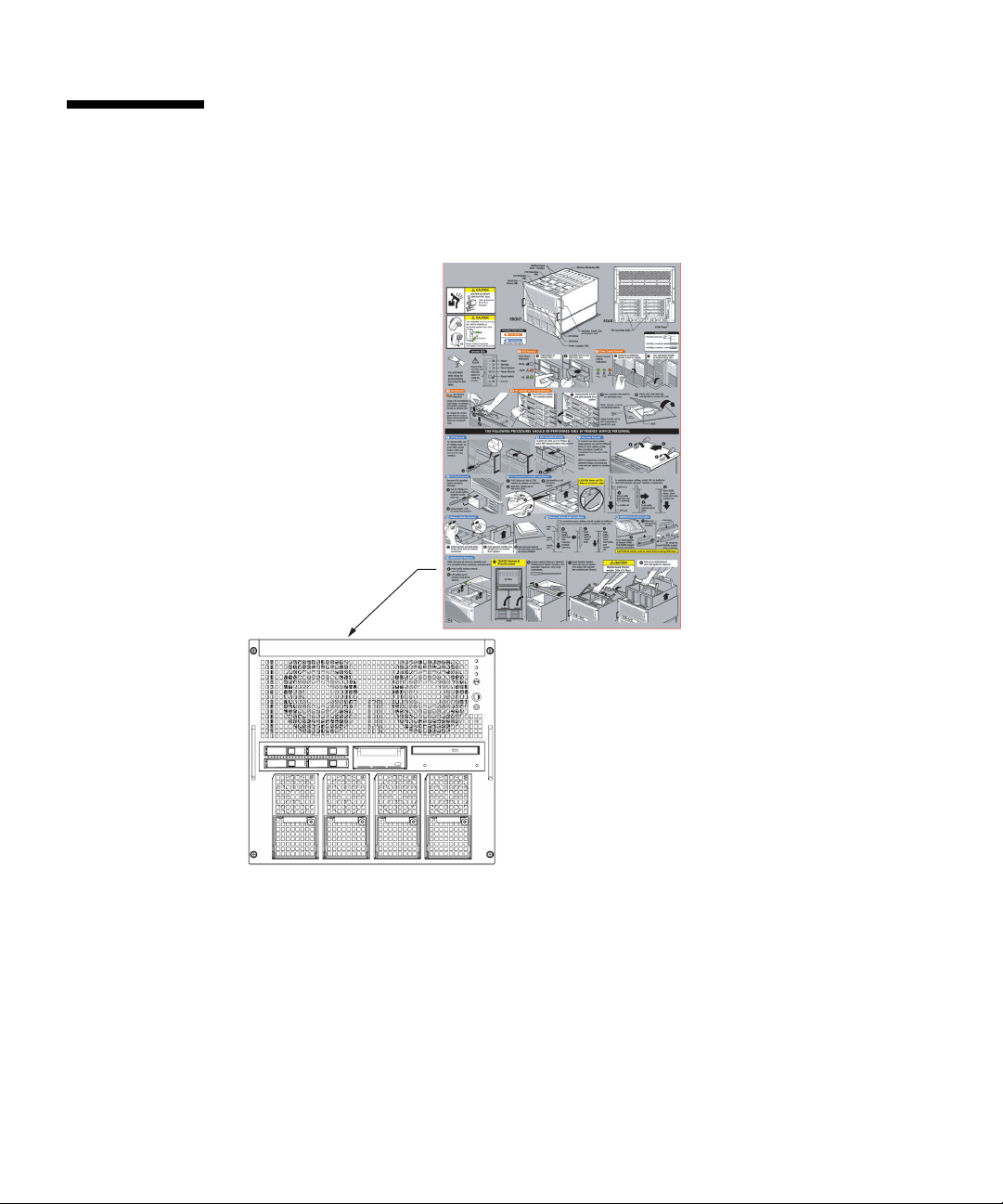
Alert Labels
FF2 (Front View)
The followings are labels attached to this product:
■ Never peel off the labels.
xxviii SPARC Enterprise M4000/M5000 Servers Service Manual • August 2009
Page 31

Product Handling
Maintenance
Caution – Certain tasks in this manual should only be performed by a certified
service engineer. User must not perform these tasks. Incorrect operation of these
tasks may cause electric shock, injury, or fire.
■ Installation and reinstallation of all components, and initial settings
■ Removal of front, rear, or side covers
■ Mounting/de-mounting of optional internal devices
■ Plugging or unplugging of external interface cards
■ Maintenance and inspections (repairing, and regular diagnosis and maintenance)
Caution – The following tasks regarding this product and the optional products
provided from Fujitsu should only be performed by a certified service engineer.
Users must not perform these tasks. Incorrect operation of these tasks may cause
malfunction.
■ Unpacking optional adapters and such packages delivered to the users
■ Plugging or unplugging of external interface cards
Remodeling/Rebuilding
Caution – Any modification and/or recycling of this product and its components
may be carried out only by a certified service engineer and must not be done by the
customer under any circumstances. Otherwise, electric shock, injury or fire may
result.
Preface xxix
Page 32

Emission of Laser Beam (Invisible)
Caution – The main unit contains modules that generate invisible laser radiation.
Laser beams are generated while the equipment is operating, even if an optical cable
is disconnected or a cover is removed. Do not look at any light-emitting part directly
or through an optical apparatus (e.g., magnifying glass, microscope).
Limitations and Cautions
Power Control and Operator Panel Mode Switch
When you use the remote power control utilizing the RCI function or the automatic power
control system (referred to below as APCS), you can disable this remote power control or the
APCS by switching to Service mode on the operator panel.
Disabling these features ensures that you do not unintentionally switch the system power on
or off during maintenance. Note system power off with the APCS cannot be disabled with
the mode switch. Therefore, be sure to turn off automatic power control via APCS before
starting maintenance.
If you switch the mode while using the RCI or the automatic power control, the system
power is controlled as follows.
Function Mode switch
Locked Service
RCI Remote power-on/power-off
operations are enabled.
Automatic
power control
To use the RCI function, see the SPARC Enterprise M3000/M4000/M5000/M8000/M9000
Servers RCI Build Procedure and the SPARC Enterprise
M3000/M4000/M5000/M8000/M9000 Servers RCI User’s Guide which are available on the
website of manuals.
To use the APCS, see the Enhanced Support Facility User's Guide for Machine
Administration Automatic Power Control Function (Supplement Edition).
xxx SPARC Enterprise M4000/M5000 Servers Service Manual • August 2009
Automatic power-on/power-off
operations are enabled.
Remote power-on/power-off
operations are disabled.
Automatic power-on is disabled,
but power-off remains enabled.
Page 33

Fujitsu Welcomes Your Comments
If you have any comments or requests regarding this document, or if you find any
unclear statements in the document, please state your points specifically on the form
at the following URL.
For Users in U.S.A., Canada, and Mexico:
http://www.computers.us.fujitsu.com/www/support_servers.shtml?su
pport/servers
For Users in Other Countries:
SPARC Enterprise contact
http://www.fujitsu.com/global/contact/computing/sparce_index.html
Preface xxxi
Page 34

xxxii SPARC Enterprise M4000/M5000 Servers Service Manual • August 2009
Page 35

CHAPTER
1
Safety and Tools
This chapter describes safety and tools information. The information is organized
into the following topics:
■ “Safety Precautions” on page 1-1
■ “System Precautions” on page 1-2
■ “System Precautions” on page 1-2
1.1 Safety Precautions
To protect both yourself and the equipment, observe the following safety
precautions.
TABLE 1-1 ESD Precautions
Item Problem Precaution
ESD
jack/wrist or
foot strap
ESD mat ESD An approved ESD mat provides protection from static damage when used
ESD
packaging
box
Electrostatic
Discharge (ESD)
ESD Place the board or component in the ESD safe packaging box after you
Connect the ESD connector to your server and wear the wrist strap or foot
strap when handling printed circuit boards. There are two antistatic strap
attachment points on the chassis:
1. Right side towards the front
2. Left side towards the rear
with a wrist strap or foot strap. The mat also cushions and protects small
parts that are attached to printed circuit boards.
remove it.
1-1
Page 36

Caution – Attach the cord of the antistatic wrist strap directly to the server. Do not
attach the antistatic wrist strap to the ESD mat connection.
The antistatic wrist strap and any components you remove must be at the same
potential.
1.2 System Precautions
For your protection, observe the following safety precautions when servicing your
equipment:
■ Follow all cautions, warnings, and instructions marked on the equipment.
■ Never push objects of any kind through openings in the equipment, as they might
touch dangerous voltage points or short out components that could result in fire
or electric shock.
■ Refer servicing of equipment to qualified personnel.
1.2.1 Electrical Safety Precautions
Ensure that the voltage and frequency of the power outlet to be used match the
electrical rating labels on the equipment.
Wear antistatic wrist straps when handling any magnetic storage devices,
system boards, or other printed circuit boards.
Use only properly grounded power outlets as described in the SPARC Enterprise
M4000/M5000 Servers Installation Guide.
Caution – Do not make mechanical or electrical modifications. The manufacturer is
not responsible for regulatory compliance of modified servers.
1.2.2 Equipment Rack Safety Precautions
All equipment racks should be anchored to the floor, ceiling, or to adjacent frames,
using the manufacturer’s instructions.
1-2 SPARC Enterprise M4000/M5000 Servers Service Manual • August 2009
Page 37

Free-standing equipment racks should be supplied with a stabilizer feature, which
must be sufficient to support the weight of the server when extended on its slides.
This prevents instability during installation or service actions.
Where a stabilizer feature is not supplied and the equipment rack is not bolted to the
floor, a safety evaluation must be conducted by the installation or service engineer.
The safety evaluation determines stability when the server is extended on its slides,
prior to any installation or service activity.
Prior to installing the equipment rack on a raised floor, a safety evaluation must be
conducted by the installation or service engineer. The safety evaluation ensures that
the raised floor has sufficient strength to withstand the forces upon it when the
server is extended on its slides. The normal procedure in this case would be to fix
the rack through the raised floor to the concrete floor below, using a proprietary
mounting kit for the purpose.
Caution – If more than one server is installed in an equipment rack, service only
one server at a time.
1.2.3 Filler Boards and Filler Panels
Filler boards and panels, which are physically inserted into the server when a board
or module has been removed are used for EMI protection and for air flow.
1.2.4 Handling Components
Caution – There is a separate ground located on the rear of the server. It is
important to ensure that the server is properly grounded.
Caution – The server is sensitive to static electricity. To prevent damage to the
board, connect an antistatic wrist strap between you and the server.
Caution – The boards have surface-mount components that can be broken by
flexing the boards.
To minimize the amount of board flexing, observe the following precautions:
Chapter 1 Safety and Tools 1-3
Page 38

■ Hold the board by the handle and finger hold panels, where the board stiffener is
located. Do not hold the board at the ends.
■ When removing the board from the packaging, keep the board vertical until you
lay it on the cushioned ESD mat.
■ Do not place the board on a hard surface. Use a cushioned antistatic mat. The
board connectors and components have very thin pins that bend easily.
■ Be careful of small component parts located on both sides of the board.
■ Do not use an oscilloscope probe on the components. The soldered pins are easily
damaged or shorted by the probe point.
■ Transport the board in its packaging box.
Caution – The heat sinks can be damaged by incorrect handling. Do not touch the
heat sinks while replacing or removing boards. If a heat sink is loose or broken,
obtain a replacement board. When storing or shipping a board, ensure that the heat
sinks have sufficient protection.
Caution – On the PCI cassette, when removing cables such as LAN cable, if your
finger can’t reach the latch lock of the connector, press the latch with a flathead
screwdriver to remove the cable. Forcing your finger into the clearance can cause
damage to the PCI card.
1-4 SPARC Enterprise M4000/M5000 Servers Service Manual • August 2009
Page 39

CHAPTER
2
Fault Isolation
This chapter describes overview and fault diagnosis information. The information is
organized into the following topics:
■ “Determining Which Diagnostics Tools to Use” on page 2-1
■ “Checking the Server and System Configuration” on page 2-4
■ “Operator Panel” on page 2-9
■ “Error Conditions” on page 2-14
■ “LED Functions” on page 2-18
■ “Using the Diagnostic Commands” on page 2-21
■ “Traditional Solaris Diagnostic Commands” on page 2-26
■ “Other Issues” on page 2-37
2.1 Determining Which Diagnostics Tools to Use
When a failure occurs, a message is often displayed on the monitor. Use the
flowcharts in
problems.
FIGURE 2-1 and FIGURE 2-2 to find the correct methods for diagnosing
2-1
Page 40

FIGURE 2-1 Diagnostic Method Flow Chart
No
2-2 SPARC Enterprise M4000/M5000 Servers Service Manual • August 2009
Page 41

FIGURE 2-2 Diagnostic Method Flow Chart—Traditional Data Collection
Chapter 2 Fault Isolation 2-3
Page 42

2.2 Checking the Server and System Configuration
Before and after maintenance work, the state and configuration of the server and
components should be checked and the information saved. For recovery from a
problem, conditions related to the problem and the repair status must be checked.
The operating conditions must remain the same before and after maintenance.
A functioning
For example:
■ The syslog file should not display error messages.
■ The XSCF Shell command showhardconf does not display the * mark.
■ The administrative console should not display error messages.
■ The server processor logs should not display any error messages.
■ The Solaris™ Operating System message files should not indicate any additional
errors.
server without any problems should not display any error conditions.
2.2.1 Checking the Hardware Configuration and FRU Status
To replace a faulty component and perform the maintenance on the server it is
important to check and understand the hardware configuration of the server and the
state of each hardware component.
The hardware configuration refers to information that indicates to which layer a
component belongs in the hardware configuration.
The status of each hardware component refers to information on the condition of the
standard or optional component in the server: temperature, power supply voltage,
CPU operating conditions, and other times.
2-4 SPARC Enterprise M4000/M5000 Servers Service Manual • August 2009
Page 43

The hardware configuration and the status of each hardware component can be
checked from the maintenance terminal using eXtended System Control Facility
(XSCF) Shell commands, as shown in the following table.
TABLE 2-1 Commands for Checking Hardware Configuration
Command Description
showhardconf Displays hardware configuration.
showstatus Displays the status of a component. This command is used when
only a faulty component is checked.
showboards Displays the status of devices and resources.
showdcl Displays the hardware resource configuration information of a
domain.
showfru Displays the setting information of a device.
Also some conditions can be checked based on the On or blinking state of the
component LEDs (see
TABLE 2-3).
2.2.1.1 Checking the Hardware Configuration
Login authority is required to check the hardware configuration. The following
procedure for these checks can be made from the maintenance terminal:
1. Log in with the account of the XSCF hardware maintenance engineer.
2. Type showhardconf.
XSCF> showhardconf
The showhardconf command prints the hardware configuration information to
the screen. See the SPARC Enterprise M3000/M4000/M5000/M8000/M9000 Servers
XSCF User’s Guide for more detailed information.
Chapter 2 Fault Isolation 2-5
Page 44

2.2.2 Checking the Software and Firmware Configuration
The software and firmware configurations and versions affect the operation of the
server. To change the configuration or investigate a problem, check the latest
information and check for any problems in the software.
Software and firmware varies according to users:
■ The software configuration and version can be checked in the Solaris OS. Refer to
the Solaris 10 documentation for more information.
■ The firmware configuration and versions can be checked from the maintenance
terminal using XSCF Shell commands. Refer to the SPARC Enterprise
M3000/M4000/M5000/M8000/M9000 Servers XSCF User’s Guide for more detailed
information.
Check the software and firmware configuration information with assistance from the
system administrator. However, if you have received login authority from the
system administrator, the commands shown in the table can be used from the
maintenance terminal for these checks.
TABLE 2-2 Commands for Checking Software and Firmware Configuration
Command Description
showrev(1M) System administration command that displays information system
patches.
uname(1) System administration command that outputs the current system
information.
version(8) XSCF Shell command that outputs the current firmware version
information.
showhardconf(8) XSCF Shell command that indicates information on components
mounted on the server.
showstatus(8) XSCF Shell command that displays the status of a component. This
command is used when only a faulty component is to be checked.
2-6 SPARC Enterprise M4000/M5000 Servers Service Manual • August 2009
Page 45

TABLE 2-2 Commands for Checking Software and Firmware Configuration (Continued)
Command Description
showboards(8) XSCF Shell command that indicates information on eXtended system
board (XSB). It can indicate information on XSB that belongs to the
specified domain and information on all XSBs mounted. The
eXtended System Board (XSB) combines the hardware resources of a
physical system board. The SPARC Enterprise servers can generate
one (Uni-XSB) or four (Quad-XSB) XSB(s) from one physical system
board.
showdcl(8) XSCF Shell command that displays the configuration information of a
domain (hardware resource information).
showfru(8) XSCF Shell command that displays the setting information of a
device.
2.2.2.1 Checking the Software Configuration
The following procedure for these checks can be made from the domain console:
1. Type showrev.
# showrev
The showrev command prints the system configuration information to the
screen.
2.2.2.2 Checking the Firmware Configuration
Login authority is required to check the firmware configuration. The following
procedure for these checks can be made from the maintenance terminal:
1. Log in with the account of the XSCF hardware maintenance engineer.
2. Type version(8).
XSCF> version(8)
The version(8) command prints the firmware version information to the
screen. See the SPARC Enterprise M3000/M4000/M5000/M8000/M9000 Servers
XSCF User’s Guide for more detailed information.
Chapter 2 Fault Isolation 2-7
Page 46

2.2.3 Downloading the Error Log Information
If you want to download the error log information, use the XSCF log fetch function.
The eXtended System Control facility unit (XSCFU) has an interface with external
units so that a maintenance engineer can easily obtain useful maintenance
information such as error logs
Connect the maintenance terminal, and use the command-line interface (CLI) or
browser user interface (BUI) to issue a download instruction to the maintenance
terminal to download Error Log information over the XSCF-LAN.
2-8 SPARC Enterprise M4000/M5000 Servers Service Manual • August 2009
Page 47

2.3 Operator Panel
1
2
3
4
5
6
When no network connection is available the operator panel is used to start or stop
the server. The operator panel displays three LED status indicators, a Power switch,
and a security keyswitch. The panel is located on the front of the server, in the upper
right.
When the server is running, the Power and XSCF STANDBY LEDs (green) should be
lit and the CHECK LED (amber) should not be lit. If the CHECK LED is lit, search
the system logs to determine what is wrong.
The three LED status indicators on the operator panel provide the following:
■ General system status
■ System problem alerts
■ Location of the system fault
FIGURE 2-3 and FIGURE 2-4 show the operator panel.
FIGURE 2-3 SPARC Enterprise M4000 Operator Panel
Location Number Component
1 POWER LED
2 XSCF STANDBY LED
3 CHECK LED
4Power switch
5 Mode switch (keyswitch)
l
Chapter 2 Fault Isolation 2-9
Page 48

Location Number Component
1
2
3
4
5
6
6 Antistatic ground socket
FIGURE 2-4 SPARC Enterprise M5000 Operator Panel
Location Number Component
1 POWER LED
2 XSCF STANDBY LED
3 CHECK LED
4Power switch
5 Mode switch (keyswitch)
6 Antistatic ground socket
Additional LEDs are located in various locations in the server. For more information
about LED indicator locations, see Section 2.5, “LED Functions” on page 2-18.
2-10 SPARC Enterprise M4000/M5000 Servers Service Manual • August 2009
Page 49

The Operator panel LEDs operate as described in TAB LE 2 -3.
TABLE 2-3 Operator Panel LEDs and Switches
Icon Name Color Description
POWER LED Green Indicates the server power status.
• On: Server has power.
• Off: Server is without power.
• Blinking: The power-off sequence is in progress.
XSCF
STANDBY
LED
Green Indicates the readiness of the XSCF.
• On: XSCF unit is functioning normally.
• Off: XSCF unit is stopped.
• Blinking: Under system initialization after server
power-on, or under system power-on process.
Indicates that server detected a fault.
CHECK LED Amber
• On: Error detected that disables the startup.
• Off: Normal, or server power-off (power failure).
• Blinking: Indicates the position of fault.
Power switch Switch to direct server power on/power off.
The Locked setting:
• Normal key position. Power on is available with the
Mode switch
(keyswitch)
Power switch, but power off is not.
• Disables the Power switch to prevent unauthorized
users from powering the server on or off.
• The Locked position is the recommended setting for
normal day-to-day operations.
The Service setting:
• Service should be provided at this position.
• Power on and off is available with Power switch.
• The key cannot be pulled out at this position.
Chapter 2 Fault Isolation 2-11
Page 50

The state displayed by LED combination is described in TAB LE 2 -4.
TABLE 2-4 State Display by LED Combination (Operator Panel)
LED
XSCF
STANDBY CHECK
Off Off Off The circuit breaker is switched off.
Off Off On The circuit breaker is switched on.
Off Blinking Off The XSCF is being initialized.
Off Blinking On An error occurred in the XSCF.
Off On Off The XSCF is on standby.
On On Off Warm-up standby processing is in progress
Blinking On Off The power-off sequence is in progress.
Description of the statePOWER
The system is waiting for power-on of the air
conditioning system.
(power-on is delayed).
The power-on sequence is in progress.
The system is in operation.
Fan termination is being delayed.
2-12 SPARC Enterprise M4000/M5000 Servers Service Manual • August 2009
Page 51

The operator panel mode switch is used to set the operation mode. The operator
panel power switch is used to power on and off the server.
TABLE 2-6 lists the settings
and corresponding functions of the mode switch on the operator panel.
TABLE 2-5 Switches (Operator Panel)
Name Description of Function
Mode switch Used to set an operation mode for the server. Insert the special key that is under the
customer’s control, to switch between modes.
Locked Normal operation mode.
The system can be powered on with the power switch, but it
cannot be powered off with the power switch.
The key can be pulled out at this key position.
Service Mode for maintenance.
The system can only be powered on and off with the power
switch.
The key cannot be pulled out at this key position.
Maintenance is performed in Service mode while the server
is stopped.
Because remote power control and automatic power control
of the server are disabled in Service mode, unintentional
power on can be prevented.
Power switch Used to control the server power. Power on and power off are controlled by pressing this
switch in different patterns, as described below.
Holding down for a short time
(less than 4 seconds)
Holding down for a long time
in Service mode
(4 seconds or longer)
Regardless of the mode switch state, the server (all domains)
is powered on.
At this time, processing for waiting for facility (air
conditioners) power on and warm-up completion is skipped.
If power to the server
operating), shutdown processing is executed for all domains
before the system is powered off.
If the system is being powered on, the power-on processing
is cancelled, and the system is powered off.
If the system is being powered off, the operation of the
Power switch is ignored, and the power-off processing is
continued.
is on (at least one domain is
Chapter 2 Fault Isolation 2-13
Page 52

TABLE 2-6 Meanings of the Mode Switch
Function Mode Switch
State Definition Locked Service
Inhibition of Break Signal Reception Enabled. Reception of the
break signal can be enabled or
disabled for each domain
using setdomainmode.
Power On/Off by power switch Only power on is enabled Enabled
Disabled
2.4 Error Conditions
Always access the following web site first to interpret faults and obtain information
on FMA messages.
http://www.sun.com/msg
This web site can be used in the event of a Solaris or domain failure or to look up
specific FMA error messages it will not provide details on XSCF errors.
The web site directs you to provide the message ID that your software displayed.
The web site then provides knowledge articles about the fault and corrective action
to resolve the fault. The fault information and documentation at this web site is
updated regularly.
Predictive self-healing is an architecture and methodology for automatically
diagnosing, reporting, and handling software and hardware fault conditions. This
new technology lessens the time required to debug a hardware or software problem
and provides the administrator and technical support with detailed data about each
fault.
2.4.1 Predictive Self-Healing Tools
In the Solaris 10 software, the fault manager runs in the background. If a failure
occurs, the system software recognizes the error and attempts to determine what
hardware is faulty. The software also takes steps to prevent that component from
being used until it has been replaced. Some of the specific actions the software takes
include:
■ Receives telemetry information about problems detected by the system software.
2-14 SPARC Enterprise M4000/M5000 Servers Service Manual • August 2009
Page 53

■ Diagnoses the problems.
■ Initiates pro-active self-healing activities. For example, the fault manager can
disable faulty components.
■ When possible, causes the faulty FRU to provide an LED indication of a fault in
addition to populating the system console messages with more details.
TABLE 2-7 shows a typical message generated when a fault occurs. The message
appears on your console and is recorded in the /var/adm/messages file.
Note – The message in TABLE 2 -7 indicates that the fault has already been diagnosed.
Any corrective action that the system can perform has already taken place. If your
server is still running, it continues to run.
Chapter 2 Fault Isolation 2-15
Page 54

TABLE 2-7 Predictive Self-Healing Message
Output Displayed Description
Nov 1 16:30:20 dt88-292 EVENT-TIME: Tue Nov 1 16:30:20
PST 2005
Nov 1 16:30:20 dt88-292 PLATFORM: SUNW,A70, CSN: -,
HOSTNAME: dt88-292
EVENT-TIME: the time stamp of
the diagnosis.
PLATFORM: A description of the
server encountering the problem.
Nov 1 16:30:20 dt88-292 SOURCE: eft, REV: 1.13 SOURCE: Information on the
Diagnosis Engine used to
determine the fault.
Nov 1 16:30:20 dt88-292 EVENT-ID: afc7e660-d609-4b2f86b8-ae7c6b8d50c4
Nov 1 16:30:20 dt88-292 DESC:
Nov 1 16:30:20 dt88-292 A problem was detected in the
EVENT-ID: The Universally
Unique event ID for this fault.
DESC: A basic description of the
failure.
PCI-Express subsystem
Nov 1 16:30:20 dt88-292 Refer to
http://sun.com/msg/SUN4-8000-0Y for more information.
WEB SITE: Where to find specific
information and actions for this
fault.
Nov 1 16:30:20 dt88-292 AUTO-RESPONSE: One or more
device instances may be disabled.
AUTO-RESPONSE: What, if
anything, the system did to
alleviate any follow-on issues.
Nov 1 16:30:20 dt88-292 IMPACT: Loss of services
provided by the device instances associated with this
IMPACT: A description of what
that response might have done.
fault.
Nov 1 16:30:20 dt88-292 REC-ACTION: Schedule a repair
procedure to replace the affected device. Use Nov 1
16:30:20 dt88-292 fmdump -v -u EVENT_ID to identify the
REC-ACTION: A short description
of what the system administrator
should do.
device or contact Sun for support.
2-16 SPARC Enterprise M4000/M5000 Servers Service Manual • August 2009
Page 55

2.4.2 Monitoring Output
To understand error conditions, collect the monitoring output information. For the
collection of the information, use the commands shown in
TABLE 2-8 Commands for Checking the Monitoring Output
Command Operand Description
showlogs(8) console Displays console of Domain.
monitor Logs messages that are displayed in the message window.
panic Logs output to the console during a panic.
ipl Collects console data generated during the period of the
power on of a domain to the completion of the operating
system start.
2.4.3 Messaging Output
To understand error conditions, collect messaging output information, use the
commands shown in
TABLE 2-9 Commands for Checking the Messaging Output
TABLE 2-9.
TABLE 2-8.
Command Operand Description
showlogs env Displays the temperature history log. The environmental
temperature data and power status are indicated in 10-minute
intervals. the data is stored for a maximum of six months.
power Displays the power and reset information.
event Displays information reported to the operating system and
stored as event logs.
error Displays error logs.
fmdump(1M)
fmdump(8)
Displays fault management architecture diagnostic results and
errors. It is provided as a Solaris command and XSCF Shell
command.
Each error message logged by the predictive self-healing architecture has a code
associated with it as well as a web address that can be followed to get the most upto-date course of action for dealing with that error.
Refer to the Solaris 10 documentation for more information on predictive selfhealing.
Chapter 2 Fault Isolation 2-17
Page 56

2.5 LED Functions
LED lights help the user find the component and provide information on the state of
the component.
This section explains the LEDs of each component that are to be checked when a
component is replaced. Most components are equipped with LEDs that help indicate
which component has the error and an LED to indicate whether the component can
be removed.
Some components, such as DIMMs, do not have LEDs. The state of a component
without LEDs can be checked using the showhardconf and ioxadm XSCF Shell
commands from the maintenance terminal. See the SPARC Enterprise
M3000/M4000/M5000/M8000/M9000 Servers XSCF User’s Guide for more detailed
information.
TABLE 2-10 describes the LEDs and their functions.
TABLE 2-10 Component LEDs
LED Name Display and Meaning
READY (green) Indicates whether the component is operating.
On Indicates that the component is operating. The component
cannot be disconnected and removed from the server while
the READY LED is On.
Blinking Indicates that the component is being configured (or
disconnected).
For an XSCF unit it indicates that it is being initialized.
Off Indicates that the component is stopped. The component can
be disconnected and replaced.
CHECK
(amber)
Indicates that the component contains an error or that the component is a
target for replacement.
On Indicates that an error has been detected.
Blinking Indicates that the component is ready to be replaced. The
blinking LED acts as a locator.
Off Indicates no known error exists.
2-18 SPARC Enterprise M4000/M5000 Servers Service Manual • August 2009
Page 57

TABLE 2-11 describes the components and their LEDs.
TABLE 2-11 Component LED Descriptions
Component LED Type LED Display Meaning
XSCF unit ACTIVE On (green) Indicates that the XSCF unit is active.
Off Indicates that the XSCF unit is on standby.
XSCF unit and IO
(display part for
LAN)
ACTIVE On (green) Indicates that the communication is being
performed through the LAN port.
Off Indicates that no communication is being
performed through the LAN port.
LINK SPEED On (amber) Indicates that the communication speed for the
LAN port is 1G bps.
On (green) Indicates that the communication speed for the
LAN port is 100M bps.
Off Indicates that the communication speed for the
LAN port is 10M bps.
PCI slot POWER On (green) Indicates that the power to the PCI slot is turned
on. The PCI card cannot be removed.
Off Indicates that the power to the PCI slot is turned
off. The PCI card can be removed.
ATTENTION On (amber) Indicates that an error occurred in the PCI slot.
Blinking (amber) Indicates that the card in this PCI slot is a target
device for replacement.
Off Indicates the normal state of the PCI slot.
Chapter 2 Fault Isolation 2-19
Page 58

TABLE 2-11 Component LED Descriptions (Continued)
Component LED Type LED Display Meaning
Power supply unit
(PSU)
READY On (green) Indicates that the power is turned on and being
supplied.
Blinking (green) Indicates that the power is being supplied to the
power supply unit, but the power supply unit is
not turned on.
Off Indicates that power is not being supplied to the
power supply unit.
CHECK On (amber) Indicates that an error occurred in the power
supply unit.
Off Indicates the normal state of the power supply
unit.
LED_AC On (green) Power supply unit has AC applied and is
supplying 12V.
Off Indicates that AC is out of the specified
operating range and 12V is not being supplied
from the power supply unit.
LED_DC On (green) Power supply unit has AC applied and is
supplying 48V. Standby pinhole provides a
manual backup to turn off 48V power.
Off Indicates that 48V is not being supplied from
the power supply unit.
Fan ATTENTION On (amber) Indicates that an error occurred.
Blinking (amber) Indicates that the fan is a target device for
replacement.
2-20 SPARC Enterprise M4000/M5000 Servers Service Manual • August 2009
Page 59
2.6 Using the Diagnostic Commands
After the message in TA BLE 2-7 is displayed, you might desire more information
about the fault. For complete information about troubleshooting commands, refer to
the Solaris 10 man pages or the XSCF Shell man pages. This section describes some
details of the following commands:
■ showlogs
■ fmdump
■ fmadm
■ fmstat
2.6.1 Using the showlogs Command
The showlogs command displays the contents of a specified log in order of time
stamp starting with the oldest date. The showlogs command displays the following
logs:
■ error log
■ power log
■ event log
■ temperature and humidity record
■ monitoring message log
■ console message log
■ panic message log
■ IPL message log
An example of the showlogs output.
XSCF> showlogs error
Date: Oct 03 17:23:11 UTC 2006 Code: 80002000-ccff0000-0104340100000000
Status: Alarm Occurred: Oct 03 17:23:10.868 UTC 2006
FRU: /FAN_A#0
Msg: Abnormal FAN rotation speed. Insufficient rotation
XSCF>
Chapter 2 Fault Isolation 2-21
Page 60

2.6.2 Using the fmdump Command
The fmdump command can be used to display the contents of any log files associated
with the Solaris fault manager.
The fmdump command produces output similar to
CODE EXAMPLE 2-1. This example
assumes there is only one fault.
CODE EXAMPLE 2-1 fmdump Output
# fmdump
TIME UUID SUNW-MSG-ID
Nov 02 10:04:15.4911 0ee65618-2218-4997-c0dc-b5c410ed8ec2 SUN4-8000-0Y
2.6.2.1 fmdump -V Command
You can obtain more detail by using the -V option.
# fmdump -V -u 0ee65618-2218-4997-c0dc-b5c410ed8ec2
TIME UUID SUNW-MSG-ID
Nov 02 10:04:15.4911 0ee65618-2218-4997-c0dc-b5c410ed8ec2 SUN4-8000-0Y
100% fault.io.fire.asic
FRU: hc://product-id=SUNW,A70/motherboard=0
rsrc: hc:///motherboard=0/hostbridge=0/pciexrc=0
At least three lines of new output are delivered to the user with the -V option.
■ The first line is a summary of information you have seen before in the console
message but includes the time stamp, the UUID and the Message-ID.
■ The second line is a declaration of the certainty of the diagnosis. In this case we
are 100 percent sure the failure is in the ASIC described. If the diagnosis might
involve multiple components you might see two lines here with 50% in each (for
example)
■ The FRU line declares the part that needs to be replaced to return the server to a
fully operational state.
■ The rsrc line describes which component was taken out of service as a result of
this fault.
2-22 SPARC Enterprise M4000/M5000 Servers Service Manual • August 2009
Page 61

2.6.2.2 fmdump -e Command
To get information of the errors that caused this failure you can use the -e option,
as shown in the following example.
XSCF> fmdump -e
TIME CLASS
Oct 03 13:52:48.9532 ereport.fm.fmd.module
Oct 03 13:52:48.9610 ereport.fm.fmd.module
Oct 03 13:52:48.9674 ereport.fm.fmd.module
Oct 03 13:52:48.9738 ereport.fm.fmd.module
2.6.3 Using the fmadm faulty Command
The fmadm faulty command can be used by administrators and service personnel
to view and modify system configuration parameters that are maintained by the
Solaris fault manager. The command is primarily used to determine the status of a
component involved in a fault, as shown in the following example.
# fmadm faulty
STATERESOURCE / UUID
-------- -------------------------------------------------------degraded dev:////pci@1e,600000
0ee65618-2218-4997-c0dc-b5c410ed8ec2
# fmadm repair
0ee65618-2218-4997-c0dc-b5c410ed8ec2
The PCI device is degraded and is associated with the same UUID as seen above.
You might also see “faulted” states.
2.6.3.1 fmadm repair Command
If fmadm faulty occurs, the faulty FRU (CPU, memory, or I/O unit) is replaced,
and then the fmadm repair command needs to be executed to clear FRU
information on the domain. If the fmadam repair command is not executed, error
messages continue to be output.
Chapter 2 Fault Isolation 2-23
Page 62

If fmadm faulty occurs, the FMA resource cache on the OS side can be cleared
without problems; the data in it need not match the hardware failure information
retained on the XSCF side.
# fmadm repair
STATERESOURCE / UUID
-------- -------------------------------------------------------degraded dev:////pci@1e,600000
0ee65618-2218-4997-c0dc-b5c410ed8ec2
2.6.3.2 fmadm config Command
The fmadm config command output shows you the version numbers of the
diagnosis engines in use by your server, as well as their current state. You can check
these versions against information on the SunSolve web site to determine if you are
running the latest diagnostic engines, as shown in the following example.
XSCF> fmadm config
MODULE VERSION STATUS DESCRIPTION
eft 1.16 active eft diagnosis engine
event-transport 2.0 active Event Transport Module
faultevent-post 1.0 active Gate Reaction Agent for errhandd
fmd-self-diagnosis 1.0 active Fault Manager Self-Diagnosis
iox_agent 1.0 active IO Box Recovery Agent
reagent 1.1 active Reissue Agent
sysevent-transport 1.0 active SysEvent Transport Agent
syslog-msgs 1.0 active Syslog Messaging Agent
XSCF>
2.6.4 Using the fmstat Command
The fmstat command can report statistics associated with the Solaris fault
manager. The fmstat command shows information about DE performance. In the
example below, the fmd-self-diagnosis DE (also seen in the console output) has
received an event which it accepted. A case is “opened” for that event and a
diagnosis is performed to “solve” the cause for the failure. See the following
example.
2-24 SPARC Enterprise M4000/M5000 Servers Service Manual • August 2009
Page 63

XSCF> fmstat
module ev_recv ev_acpt wait svc_t %w %b open solve memsz bufsz
eft 0 0 0.0 0.0 0 0 0 0 3.3M 0
event-transport 0 0 0.0 0.0 0 0 0 0 6.4K 0
faultevent-post 2 0 0.0 8.9 0 0 0 0 0 0
fmd-self-diagnosis 24 24 0.0 352.1 0 0 1 0 24b 0
iox_agent 0 0 0.0 0.0 0 0 0 0 0 0
reagent 0 0 0.0 0.0 0 0 0 0 0 0
sysevent-transport 0 0 0.0 8700.4 0 0 0 0 0 0
syslog-msgs 0 0 0.0 0.0 0 0 0 0 97b 0
XSCF>
Chapter 2 Fault Isolation 2-25
Page 64

2.7 Traditional Solaris Diagnostic Commands
These superuser commands can help you determine if you have issues in your
workstation, in the network, or within another server that you are networking with.
The following commands are described in this section:
■ “Using the iostat Command” on page 2-27
■ “Using the prtdiag Command” on page 2-28
■ “Using the prtconf Command” on page 2-30
■ “Using the netstat Command” on page 2-32
■ “Using the ping Command” on page 2-34
■ “Using the ps Command” on page 2-35
■ “Using the prstat Command” on page 2-36
Most of these commands are located in the /usr/bin or /usr/sbin directories.
Note – For additional details, options, examples, and the most up to date
information for each command refer to that command’s man page.
2-26 SPARC Enterprise M4000/M5000 Servers Service Manual • August 2009
Page 65

2.7.1 Using the iostat Command
The iostat command iteratively reports terminal, drive, and tape I/O activity, as
well as CPU utilization.
2.7.1.1 Options
TABLE 2-12 describes options for the iostat command and how those options can
help troubleshoot the server.
TABLE 2-12 Options for iostat
Option Description How It Can Help
No option Reports status of local I/O devices. A quick three-line output of device status.
-c Reports the percentage of time the
system has spent in user mode, in system
mode, waiting for I/O, and idling.
-e Displays device error summary statistics.
The total errors, hard errors, soft errors,
and transport errors are displayed.
-E Displays all device error statistics. Provides information about devices: manufacturer,
-n Displays names in descriptive format. Descriptive format helps identify devices.
-x For each drive, reports extended drive
statistics. The output is in tabular form.
Quick report of CPU status.
Provides a short table with accumulated errors.
Identifies suspect I/O devices.
model number, serial number, size, and errors.
Similar to the
information. This helps identify poor performance of
internal devices and other I/O devices across the
network.
-e option, but provides rate
The following example shows output for one iostat command.
# iostat -En
c0t0d0 Soft Errors: 0 Hard Errors: 0 Transport Errors: 0
Vendor: SEAGATE Product: ST973401LSUN72G Revision: 0556 Serial No: 0521104T9D
Size: 73.40GB <73400057856 bytes>
Media Error: 0 Device Not Ready: 0 No Device: 0 Recoverable: 0
Illegal Request: 0 Predictive Failure Analysis: 0
c0t1d0 Soft Errors: 0 Hard Errors: 0 Transport Errors: 0
Vendor: SEAGATE Product: ST973401LSUN72G Revision: 0556 Serial No: 0521104V3V
Size: 73.40GB <73400057856 bytes>
Media Error: 0 Device Not Ready: 0 No Device: 0 Recoverable: 0
Illegal Request: 0 Predictive Failure Analysis: 0
#
Chapter 2 Fault Isolation 2-27
Page 66

2.7.2 Using the prtdiag Command
The prtdiag command displays configuration and diagnostic information. The
diagnostic information identifies any failed component.
The prtdiag command is located in the /usr/platform/platform-name/sbin/
directory.
Note – The prtdiag command might indicate a slot number different than that
identified elsewhere in this document. This is normal.
2.7.2.1 Options
TABLE 2-13 describes options for the prtdiag command and how those options can
help troubleshooting.
TABLE 2-13 Options for prtdiag
Option Description How It Can Help
No option Lists components. Identifies CPU timing and PCI cards installed.
-v Verbose mode. Displays the
time of the most recent AC
power failure and the most
recent hardware fatal error
information.
Provides the same information as no option. Additionally
lists fan status, temperatures, ASIC, and PROM revisions.
2-28 SPARC Enterprise M4000/M5000 Servers Service Manual • August 2009
Page 67

The following example shows output for the prtdiag command in verbose mode.
# prtdiag -v
System Configuration: Sun Microsystems sun4u Sun SPARC Enterprise M5000 Server
System clock frequency: 1012 MHz
Memory size: 8064 Megabytes
==================================== CPUs ====================================
CPU CPU Run L2$ CPU CPU
LSB Chip ID MHz MB Impl. Mask
--- ---- -------------------- ---- --- ----- --- 00 0 0, 1, 2, 3 2150 4.0 6 129
00 1 8, 9, 10, 11 2150 4.0 6 129
====================== Memory Configuration ======================
Memory Available Memory DIMM Number of
LSB Group Size Status Size DIMMs
--- ------ ------------------ ------- ------ -------- 00 A 4096MB okay 1024MB 8
00 B 3968MB okay 1024MB 8
========================= IO Cards =========================
LSB Name Model
--- -------------- ----------- 00 scsi LSI,1064
00 network N/A
00 network N/A
00 network SUNW,pci-ce
00 fp N/A
00 SUNW,qlc QLE2462
00 fp N/A
00 SUNW,qlc QLE2462
==================== Hardware Revisions ====================
System PROM revisions:
----------------------
OBP 4.x.build_103***PROTOTYPE BUILD*** 2006/08/01 02:06
=================== Environmental Status ===================
Mode switch is in UNLOCK mode
#
Chapter 2 Fault Isolation 2-29
Page 68

2.7.3 Using the prtconf Command
Similar to the show-devs command run at the ok prompt, the prtconf command
displays the devices that are configured.
The prtconf command identifies hardware that is recognized by the Solaris OS. If
hardware is not suspected of being bad yet software applications are having trouble
with the hardware, the prtconf command can indicate if the Solaris software
recognizes the hardware, and if a driver for the hardware is loaded.
2.7.3.1 Options
TABLE 2-14 describes options for the prtconf command and how those options can
help troubleshooting.
TABLE 2-14 Options for prtconf
Option Description How It Can Help
No option Displays the device tree of
devices recognized by the OS.
-D Similar to the output of no
option, however the device
driver is listed.
-p Similar to the output of no
option, yet is abbreviated.
-V Displays the version and date of
the OpenBoot PROM firmware.
If a hardware device is recognized, then it is probably
functioning properly. If the message “
attached)
device, then the driver for the device is corrupt or missing.
Lists the driver needed or used by the OS to enable the
device.
Reports a brief list of the devices.
Provides a quick check of firmware version.
” is displayed for the device or for a sub-
(driver not
The following example shows output for the prtconf command.
# prtconf
System Configuration: Sun Microsystems sun4u
Memory size: 8064 Megabytes
System Peripherals (Software Nodes):
SUNW,SPARC-Enterprise
scsi_vhci, instance #0
packages (driver not attached)
SUNW,builtin-drivers (driver not attached)
deblocker (driver not attached)
2-30 SPARC Enterprise M4000/M5000 Servers Service Manual • August 2009
Page 69

The prtconf output continued.
disk-label (driver not attached)
terminal-emulator (driver not attached)
obp-tftp (driver not attached)
ufs-file-system (driver not attached)
chosen (driver not attached)
openprom (driver not attached)
client-services (driver not attached)
options, instance #0
aliases (driver not attached)
memory (driver not attached)
virtual-memory (driver not attached)
pseudo-console, instance #0
nvram (driver not attached)
pseudo-mc, instance #0
cmp (driver not attached)
core (driver not attached)
cpu (driver not attached)
cpu (driver not attached)
core (driver not attached)
cpu (driver not attached)
cpu (driver not attached)
cmp (driver not attached)
core (driver not attached)
cpu (driver not attached)
cpu (driver not attached)
core (driver not attached)
cpu (driver not attached)
cpu (driver not attached)
pci, instance #0
ebus, instance #0
flashprom (driver not attached)
serial, instance #0
scfc, instance #0
panel, instance #0
pci, instance #0
pci, instance #0
pci, instance #1
pci, instance #3
scsi, instance #0
tape (driver not attached)
disk (driver not attached)
sd, instance #0 (driver not attached)
sd, instance #2
sd, instance #4
network, instance #0
network, instance #1 (driver not attached)
pci, instance #4
Chapter 2 Fault Isolation 2-31
Page 70

network, instance #0 (driver not attached)
pci, instance #2
SUNW,qlc, instance #0
fp (driver not attached)
disk (driver not attached)
fp, instance #2
SUNW,qlc, instance #1
fp (driver not attached)
disk (driver not attached)
fp, instance #0
pci, instance #1
pci, instance #15
pci, instance #16
pci, instance #25
pci, instance #31
pci, instance #32
pci, instance #33
pci, instance #18
pci, instance #29
pci, instance #34
pci, instance #35
pci, instance #36
pci, instance #2
pci, instance #5
pci, instance #6
pci, instance #7
pci, instance #8
pci, instance #9
pci, instance #10
pci, instance #11
pci, instance #12
pci, instance #13
pci, instance #14
pci, instance #3
os-io (driver not attached)
iscsi, instance #0
pseudo, instance #0
#
2.7.4 Using the netstat Command
The netstat command displays the network status.
2-32 SPARC Enterprise M4000/M5000 Servers Service Manual • August 2009
Page 71

2.7.4.1 Options
TABLE 2-15 describes options for the netstat command and how those options can
help troubleshooting.
TABLE 2-15 Options for netstat
Option Description How It Can Help
-i Displays the interface state,
including packets in/out, error
in/out, collisions, and queue.
-i interval Providing a trailing number
with the
-i option repeats the
netstat command every
interval seconds.
-p Displays the media table. Provides MAC address for hosts on the subnet.
-r Displays the routing table. Provides routing information.
-n Replaces host names with IP
addresses.
following example shows output for the netstat -p command.
The
# netstat -p
Net to Media Table: IPv4
Device IP Address Mask Flags Phys Addr
------ -------------------- --------------- -------- --------------bge0 san-ff1-14-a 255.255.255.255 o 00:14:4f:3a:93:61
bge0 san-ff2-40-a 255.255.255.255 o 00:14:4f:3a:93:85
sppp0 224.0.0.22 255.255.255.255
bge0 san-ff2-42-a 255.255.255.255 o 00:14:4f:3a:93:af
bge0 san09-lab-r01-66 255.255.255.255 o 00:e0:52:ec:1a:00
sppp0 192.168.1.1 255.255.255.255
bge0 san-ff2-9-b 255.255.255.255 o 00:03:ba:dc:af:2a
bge0 bizzaro 255.255.255.255 o 00:03:ba:11:b3:c1
bge0 san-ff2-9-a 255.255.255.255 o 00:03:ba:dc:af:29
bge0 racerx-b 255.255.255.255 o 00:0b:5d:dc:08:b0
bge0 224.0.0.0 240.0.0.0 SM 01:00:5e:00:00:00
#
Provides a quick overview of the network status.
Identifies intermittent or long duration network events.
By piping
can be viewed all at once.
Used when an address is more useful than a host name.
netstat output to a file, overnight activity
Chapter 2 Fault Isolation 2-33
Page 72

2.7.5 Using the ping Command
The ping command sends ICMP ECHO_REQUEST packets to network hosts.
Depending on how the ping command is configured, the output displayed can
identify troublesome network links or nodes. The destination host is specified in the
variable hostname.
2.7.5.1 Options
TABLE 2-16 describes options for the ping command and how those options can help
troubleshooting.
TABLE 2-16 Options for ping
Option Description How It Can Help
hostname The probe packet is sent to
hostname and returned.
-g hostname Forces the probe packet to route
through a specified gateway.
-i interface Designates which interface to
send and receive the probe
packet through.
-n Replaces host names with IP
addresses.
-s Pings continuously in one-second
intervals. Ctrl-C aborts. Upon
abort, statistics are displayed.
-svR Displays the route the probe
packet followed in one-second
intervals.
Verifies that a host is active on the network.
By identifying different routes to the target host, those
individual routes can be tested for quality.
Enables a simple check of secondary network interfaces.
Used when an address is more beneficial than a host name.
Helps identify intermittent or long-duration network events.
By piping
be viewed at once.
Indicates probe packet route and number of hops.
Comparing multiple routes can identify bottlenecks.
ping output to a file, activity overnight can later
following example shows output for the ping -s command.
The
# ping -s san-ff2-17-a
PING san-ff2-17-a: 56 data bytes
64 bytes from san-ff2-17-a (10.1.67.31): icmp_seq=0. time=0.427 ms
64 bytes from san-ff2-17-a (10.1.67.31): icmp_seq=1. time=0.194 ms
^C
----san-ff2-17-a PING Statistics---2 packets transmitted, 2 packets received, 0% packet loss
round-trip (ms) min/avg/max/stddev = 0.172/0.256/0.427/0.102
#
2-34 SPARC Enterprise M4000/M5000 Servers Service Manual • August 2009
Page 73

2.7.6 Using the ps Command
The ps command lists the status of processes. Using options and rearranging the
command output can assist in determining the resource allocation.
2.7.6.1 Options
TABLE 2-17 describes options for the ps command and how those options can help
troubleshooting.
TABLE 2-17 Options for ps
Option Description How It Can Help
-e Displays information for every
process.
-f Generates a full listing. Provides the following process information: user ID,
-o option Enables configurable output. The pid,
pcpu, pmem, and comm options
display process ID, percent CPU
consumption, percent memory
consumption, and the responsible
executable, respectively.
Identifies the process ID and the executable.
parent process ID, time when executed, and the path to
the executable.
Provides only most important information. Knowing
the percentage of resource consumption helps identify
processes that are affecting performance and might be
hung.
following example shows output for one ps command.
The
# ps
PID TTY TIME CMD
101042 pts/3 0:00 ps
101025 pts/3 0:00 sh
#
Note – When using sort with the -r option, the column headings are printed so
that the value in the first column is equal to zero.
Chapter 2 Fault Isolation 2-35
Page 74

2.7.7 Using the prstat Command
The prstat utility iteratively examines all active processes and reports statistics
based on the selected output mode and sort order. The prstat command provides
output similar to the ps command.
2.7.7.1 Options
TABLE 2-18 describes options for the prstat command and how those options can
help troubleshooting.
TABLE 2-18 Options for prstat
Option Description How It Can Help
No option Displays a sorted list of the top
processes that are consuming
the most CPU resources. List is
limited to the height of the
terminal window and the total
number of processes. Output is
automatically updated every
five seconds. Ctrl-C aborts.
-n number Limits output to number of
lines.
-s key Permits sorting list by key
parameter.
-v Verbose mode. Displays additional parameters.
Output identifies process ID, user ID, memory used, state,
CPU consumption, and command name.
Limits amount of data displayed and identifies primary
resource consumers.
Useful keys are cpu (default), time, and size.
The following example shows output for the prstat command.
# prstat -n 5 -s size
PID USERNAME SIZE RSS STATE PRI NICE TIME CPU PROCESS/NLWP
100463 root 66M 61M sleep 59 0 0:01:03 0.0% fmd/19
100006 root 11M 9392K sleep 59 0 0:00:09 0.0% svc.configd/16
100004 root 10M 8832K sleep 59 0 0:00:04 0.0% svc.startd/14
100061 root 9440K 6624K sleep 59 0 0:00:01 0.0% snmpd/1
100132 root 8616K 5368K sleep 59 0 0:00:04 0.0% nscd/35
Total: 52 processes, 188 lwps, load averages: 0.00, 0.00, 0.00
#
2-36 SPARC Enterprise M4000/M5000 Servers Service Manual • August 2009
Page 75

2.8 Other Issues
2.8.1 Can’t Locate Boot Device
When the PCI-X card slot 0 is faulty or it is not seated properly, the firmware will
blacklist the entire PCI-X bridge device (and everything attached downstream from
it) causing the boot disk to disappear. The problem results in the showdisk
command failing to display the boot disk and the bootdisk command displaying
the console message “Can’t locate boot device”.
When this occurs remove the PCI/PCI-X card in slot 0 to see if the boot issue is
remedied. If the IO unit is fully stocked and it is not possible to remove the
PCI/PCI-X card, then you should attempt to place another card in slot 0, if possible.
If this also is not possible you should remove and reinstalling the existing card in
slot 0.
Chapter 2 Fault Isolation 2-37
Page 76

2-38 SPARC Enterprise M4000/M5000 Servers Service Manual • August 2009
Page 77

CHAPTER
3
Periodic Maintenance
This chapter describes the periodic maintenance required to keep the server running
regardless of whether a problem has occurred.
3.1 Tape Drive Unit
It might be necessary to use a cleaning tape when carrying out the cleaning
procedure.
Note – Contact your sales representative for tape drive unit options on SPARC
Enterprise M4000/M5000 servers.
3.1.1 Cleaning the Tape Drive Unit
To avoid the "Clean Lamp" from prematurely illuminating, the following
maintenance rules should be followed:
■ Clean your tape drive unit once every 5 to 24 hours of continuous use, or once a
week.
■ Clean your tape drive unit once a month, even if it is not in use.
■ Clean your tape drive unit whenever the "Clean Lamp" indicator is lit or blinking.
■ Clean your tape drive unit before inserting a new data cassette.
■ Replace the cleaning cassette when the tape inside of the cassette has completely
wound up onto the right-hand spool or when the three lamps are in the following
states:"Off","Lit" and "Blinking."
3-1
Page 78

■ Remove the cassette before turning the power "OFF". The tape life might be
shortened or a malfunction might occur during the backup process if the power is
turned "OFF" while the cassette is still inside.
Note – If the "cleaning lamp" starts blinking immediately after completion of a
cleaning operation, the data cassette might have been damaged. In this case, replace
the data cassette.
3-2 SPARC Enterprise M4000/M5000 Servers Service Manual • August 2009
Page 79

CHAPTER
4
FRU Replacement Preparation
This chapter describes how to prepare a field-replaceable unit (FRU) for safe
replacement. The information is organized into the following topics:
■ “FRU Replacement Method” on page 4-1
■ “Active Replacement” on page 4-4
■ “Hot Replacement” on page 4-6
■ “Cold Replacement (Powering the Server Off and On)” on page 4-12
4.1 FRU Replacement Method
There are three basic methods for replacing the FRUs:
Active replacement – To replace a FRU while the domain, to which the FRU belongs,
continues running. Active replacement requires that the FRU be inactivated or
powered down using either an XSCF command or Solaris OS command. Because the
power supply unit (PSU) and fan unit (FAN) do not belong to any domain, they are
operated by using XSCF commands, regardless of the operating state of the Solaris
OS.
Note – The procedure for isolating the hard disk drive from the Solaris OS varies
depending on whether disk mirroring software or other support software is used.
For details, see the relevant software manuals.
Hot replacement –To replace a FRU while the domains are powered off. Depending
on the FRU to be replaced, the FRU can either be directly replaced or be inactivated
or powered down using an XSCF command.
Cold replacement – To replace a FRU while all domains are stopped and the server
is powered off and unplugged.
4-1
Page 80

TABLE 4-1 lists the FRUs, location and access, and the replacement method.
TABLE 4-1 FRU Replacement Information
FRU FRU Location/Access Removal Method(s)
PCI cassette (PCIe) Rear Active replacement (cfgadm)
Hot replacement
Cold replacement
Hard disk drive (HDD) Front Active replacement (cfgadm)
Hot replacement
Cold replacement
*
Power supply unit (PSU) Front Active replacement
(replacefru)
Hot replacement (replacefru)
Cold replacement
\
172-mm fans (FAN_A) Top Active replacement
(replacefru)
Hot replacement(replacefru)
Cold replacement
60-mm fans (FAN_B) Top Active replacement (replacefru)
Hot replacement (replacefru)
Cold replacement
Tape drive unit (TAPEU) Front Active replacement
Hot replacement
Cold replacement
I/O unit (IOU) Rear Cold replacement
I/O unit DC-DC Converter Rear Cold replacement
I/O unit DDC Riser (DDCR) Rear Cold replacement
CD-RW/DVD-RW Drive Unit (DVDU) Front Hot replacement
Cold replacement
Backplane unit (BPU_A, BPU_B) Top Cold replacement
4-2 SPARC Enterprise M4000/M5000 Servers Service Manual • August 2009
Page 81

TABLE 4-1
FRU FRU Location/Access Removal Method(s)
FRU Replacement Information (Continued)
CPU module (CPUM_A) Top Cold replacement
Memory board (MEMB) Top Cold replacement
Motherboard (SPARC Enterprise M4000)
Rear Cold replacement
(MBU_A)
Motherboard DC-DC Converter (SPARC
Rear Cold replacement
Enterprise M4000) (DDC_A, DDC_B)
Motherboard (SPARC Enterprise M5000)
Top Cold replacement
(MBU_B)
Motherboard DC-DC Converter (SPARC
Top Cold replacement
Enterprise M5000) (DDC_A, DDC_B)
eXtended System Control facility unit (XSCFU) Rear Cold replacement
Hard disk drive backplane (HDDBP) Top Cold replacement
CD-RW/DVD-RW backplane Top Cold replacement
Tape drive backplane (TAPEBP) Top Cold replacement
Operator panel (OPNL) Top Cold replacement
* When using active replacement for a PSU, only one power supply unit should be replaced at a time to ensure redundancy.
\ When using active replacement for a 172-mm or 60-mm fan unit, only one fan unit should be replaced at a time to ensure redundancy.
Chapter 4 FRU Replacement Preparation 4-3
Page 82

4.2 Active Replacement
In active replacement the Solaris OS must be configured to allow the component to
be replaced. Active replacement has four stages:
■ “Removing a FRU From a Domain” on page 4-4
■ “Removing and Replacing a FRU” on page 4-5
■ “Adding a FRU Into a Domain” on page 4-5
■ “Verifying Hardware Operation” on page 4-6
Note – If the hard disk drive is the boot device, the hard disk will have to be
replaced using cold replacement procedures. However, active replacement can be
used if the boot disk can be isolated from the Solaris OS by disk mirroring software
and other software.
4.2.1 Removing a FRU From a Domain
Note – Before you remove a PCI cassette, make sure that there is no I/O activity on
the card in the cassette.
1. From the Solaris prompt, type the cfgadm command to get the component
status.
# cfgadm -a
Ap_Id Type Receptacle Occupant
Condition
iou#0-pci#0 etherne/hp connected configured ok
iou#0-pci#1 fibre/hp connected configured ok
iou#0-pci#2 pci-pci/hp connected configured ok
Ap_Id includes the IOU number (iou#0 or iou#1) and the PCI cassette slot number
(pci#1, pci#2, pci#3, pci#4).
2. Type the cfgadm command to disconnect the component from the domain:
# cfgadm -c unconfigure Ap_Id
4-4 SPARC Enterprise M4000/M5000 Servers Service Manual • August 2009
Page 83

Note – For a PCI cassette, type the cfgadm -c disconnect command to
disconnect the component from the domain.
The Ap_Id is shown in the output of cfgadm.
3. Type the cfgadm command to confirm the component is now disconnected.
# cfgadm -a
Ap_Id Type Receptacle Occupant
Condition
iou#0-pci#0 etherne/hp disconnected unconfigured
unknown
iou#0-pci#1 fibre/hp connected configured ok
iou#0-pci#2 pci-pci/hp connected configured ok
iou#0-pci#0 for example.
4.2.2 Removing and Replacing a FRU
Once the FRU has been removed from the domain, see “Removing and Replacing a
FRU” on page 4-7
4.2.3 Adding a FRU Into a Domain
1. From the Solaris prompt, type the cfgadm command to connect the component
to the domain.
# cfgadm -c configure Ap_Id
The Ap_Id is shown in the output of cfgadm.
2. Type the cfgadm command to confirm the component is now connected.
# cfgadm -a
Ap_Id Type Receptacle Occupant
Condition
iou#0-pci#0 etherne/hp connected configured ok
iou#0-pci#1 fibre/hp connected configured ok
iou#0-pci#2 pci-pci/hp connected configured ok
iou#0-pci#0 for example.
Chapter 4 FRU Replacement Preparation 4-5
Page 84

4.2.4 Verifying Hardware Operation
● Verify the state of the status LEDs.
The POWER LED should be On and the CHECK LED should not be On.
Note – Note - If the hard disk drive is the boot device, the hard disk will have to be
replaced using cold replacement procedures. However, active replacement can be
used if the boot disk can be isolated from the Solaris OS by disk mirroring software
and other software.
4.3 Hot Replacement
In hot replacement the Solaris OS does not need to be configured to allow the
component to be replaced. Depending on the FRU to be replaced, the FRU can either
be directly replaced or be inactivated or powered down using an XSCF command.
4-6 SPARC Enterprise M4000/M5000 Servers Service Manual • August 2009
Page 85

4.3.1 Removing and Replacing a FRU
1. From the XSCF Shell prompt, type the replacefru command.
CODE EXAMPLE 4-1 replacefru command
XSCF> replacefru
---------------------------------------------------------------Maintenance/Replacement Menu
Please select a type of FRU to be replaced.
1. FAN (Fan Unit)
2. PSU (Power Supply Unit)
----------------------------------------------------------------
Select [1,2|c:cancel] :1
---------------------------------------------------------------Maintenance/Replacement Menu
Please select a FAN to be replaced.
No. FRU Status
--- --------------- ------------------
1. FAN_A#0 Faulted
2. FAN_A#1 Normal
3. FAN_A#2 Normal
4. FAN_A#3 Normal
---------------------------------------------------------------Select [1-4|b:back] :1
You are about to replace FAN_A#0.
Do you want to continue?[r:replace|c:cancel] :r
Please confirm the CHECK LED is blinking.
If this is the case, please replace FAN_A#0.
After replacement has been completed, please select[f:finish] :f
Chapter 4 FRU Replacement Preparation 4-7
Page 86

The replacefru command automatically tests the status of the component after the
remove and replace is finished.
CODE EXAMPLE 4-2 replacefru command status
Diagnostic tests of FAN_A#0 is started.
[This operation may take up to 2 minute(s)]
(progress scale reported in seconds)
0..... 30..... 60..... 90.....done
---------------------------------------------------------------Maintenance/Replacement Menu
Status of the replaced unit.
FRU Status
------------- -------FAN_A#0 Normal
---------------------------------------------------------------The replacement of FAN_A#0 has completed, normally.[f:finish] :f
---------------------------------------------------------------Maintenance/Replacement Menu
Please select a type of FRU to be replaced.
1. FAN (Fan Unit)
2. PSU (Power Supply Unit)
---------------------------------------------------------------Select [1,2|c:cancel] : C
XSCF>
Note – The display may vary depending on the XCP version.
When the tests are complete the program returns to the original menu. Select cancel
to return to the XSCF Shell prompt.
Refer to the replacefru man page for more information.
4-8 SPARC Enterprise M4000/M5000 Servers Service Manual • August 2009
Page 87

4.3.2 Verifying Hardware Operation
1. Type the showhardconf command to confirm the new component is installed.
CODE EXAMPLE 4-3 showhardconf
XSCF> showhardconf
SPARC Enterprise M5000;
+ Serial:BCF07500B6; Operator_Panel_Switch:Locked;
+ Power_Supply_System:Dual; SCF-ID:XSCF#0;
+ System_Power:On; System_Phase:Cabinet Power On;
Domain#0 Domain_Status:Initialization Phase;
Domain#1 Domain_Status:Initialization Phase;
MBU_B Status:Normal; Ver:0201h; Serial:BC07490823 ;
+ FRU-Part-Number:CF00541-0478 05 /541-0478-05 ;
+ Memory_Size:64 GB;
CPUM#0-CHIP#0 Status:Normal; Ver:0501h; Serial:PP0723016Q ;
+ FRU-Part-Number:CA06761-D204 A0 /LGA-JUPP-01 ;
+ Freq:2.530 GHz; Type:32;
+ Core:4; Strand:2;
:
CPUM#3-CHIP#1 Status:Normal; Ver:0501h; Serial:PP074804E9 ;
+ FRU-Part-Number:CA06761-D204 A0 /LGA-JUPP-01 ;
+ Freq:2.530 GHz; Type:32;
+ Core:4; Strand:2;
MEMB#0 Status:Normal; Ver:0101h; Serial:BF09061G0E ;
+ FRU-Part-Number:CF00541-0545 06 /541-0545-06 ;
MEM#0A Status:Normal;
+ Code:c1000000000000005372T128000HR3.7A 356d-0d016912;
+ Type:1A; Size:1 GB;
:
MEM#3B Status:Normal;
+ Code:c1000000000000004572T128000HR3.7A 252b-04123424;
+ Type:1A; Size:1 GB;
:
MEMB#7 Status:Normal; Ver:0101h; Serial:BF09061GBA ;
+ FRU-Part-Number:CF00541-0545 06 /541-0545-06 ;
MEM#0A Status:Normal;
+ Code:2cffffffffffffff0818HTF12872Y-53EB3 0300-d504600c;
+ Type:1A; Size:1 GB;
:
MEM#3B Status:Normal;
+ Code:7f7ffe00000000004aEBE10RD4AGFA-5C-E 3020-2229c19c;
+ Type:1A; Size:1 GB;
Chapter 4 FRU Replacement Preparation 4-9
Page 88

This sample shows the showhardconf output continued.
CODE EXAMPLE 4-4 showhardconf
DDC_A#0 Status:Normal;
DDC_A#1 Status:Normal;
DDC_A#2 Status:Normal;
DDC_A#3 Status:Normal;
DDC_B#0 Status:Normal;
DDC_B#1 Status:Normal;
IOU#0 Status:Normal; Ver:0101h; Serial:BF07486TEU ;
+ FRU-Part-Number:CF00541-2240 02 /541-2240-02 ;
DDC_A#0 Status:Normal;
DDCR Status:Normal;
DDC_B#0 Status:Normal;
IOU#1 Status:Normal; Ver:0101h; Serial:BF073226HP ;
+ FRU-Part-Number:CF00541-2803 01 /541-2803-01 ;
DDC_A#0 Status:Normal;
DDCR Status:Normal;
DDC_B#0 Status:Normal;
XSCFU Status:Normal,Active; Ver:0101h; Serial:BF07435D98 ;
+ FRU-Part-Number:CF00541-0481 04 /541-0481-04 ;
OPNL Status:Normal; Ver:0101h; Serial:BF0747690D ;
+ FRU-Part-Number:CF00541-0850 06 /541-0850-06 ;
PSU#0 Status:Normal; Serial:0017527-0738063762;
+ FRU-Part-Number:CF00300-1898 0350 /300-1898-03-50;
+ Power_Status:Off; AC:200 V;
PSU#3 Status:Normal; Serial:0017527-0738063767;
+ FRU-Part-Number:CF00300-1898 0350 /300-1898-03-50;
+ Power_Status:Input fail; AC: - ;
FANBP_C Status:Normal; Ver:0501h; Serial:FF2#24 ;
+ FRU-Part-Number:CF00541-3099 01 /541-3099-01 ;
FAN_A#0 Status:Normal;
FAN_A#1 Status:Normal;
FAN_A#2 Status:Normal;
FAN_A#3 Status:Normal;
Refer to the showhardconf man page for more information.
4-10 SPARC Enterprise M4000/M5000 Servers Service Manual • August 2009
Page 89

2. Type the showhardconf -u command to display the number of FRUs in each
unit.
CODE EXAMPLE 4-5 showhardconf -u
XSCF> showhardconf -u
SPARC Enterprise M5000; Memory_Size:64 GB;
+-----------------------------------+------------+
| FRU | Quantity |
+-----------------------------------+------------+
| MBU_B | 1 |
| CPUM | 4 |
| Freq:2.530 GHz; | ( 8) |
| MEMB | 8 |
| MEM | 64 |
| Type:1A; Size:1 GB; | ( 64) |
| DDC_A | 4 |
| DDC_B | 2 |
| IOU | 2 |
| DDC_A | 2 |
| DDCR | 2 |
| DDC_B | 2 |
| XSCFU | 1 |
| OPNL | 1 |
| PSU | 4 |
| FANBP_C | 1 |
| FAN_A | 4 |
+-----------------------------------+------------+
Refer to the showhardconf -u man page for more information.
3. Verify the state of the status LEDs on the FRU.
Refer to
TABLE 2-11 for LED status.
Chapter 4 FRU Replacement Preparation 4-11
Page 90

4.4 Cold Replacement (Powering the Server Off and On)
In cold replacement all business operations are stopped. Cold replacement is the act
of powering off the server and disconnecting input power. This is normally required
for safety when the inside of the server is accessed.
Note – The input power cables are used to ground the server. If the server is not
mounted in a rack use a grounding strap to ground the server.
Note – After a complete chassis power cycle (all power cords removed), make
certain to allow 30 seconds before plugging the power cords back into the chassis.
4.4.1 Powering the Server Off Using Software
1. Notify users that the server is being powered off.
2. Back up the system files and data to tape, if necessary.
3. Log in to the XSCF Shell and type the poweroff command.
XSCF> poweroff -a
The following actions occur when the poweroff command is used:
■ The Solaris OS shuts down cleanly.
■ The server powers off to Standby mode (the XSCF unit and one fan will still have
power).
Refer to the SPARC Enterprise M3000/M4000/M5000/M8000/M9000 Servers XSCF
User’s Guide for details.
4. Verify the state of the status LED on the XSCF.
The POWER LED should be off.
5. Disconnect all power cables from the input power source.
4-12 SPARC Enterprise M4000/M5000 Servers Service Manual • August 2009
Page 91

Caution – There is an electrical hazard if the power cords are not disconnected. All
power cords must be disconnected to completely remove power from the server.
4.4.2 Powering the Server On Using Software
1. Make sure that the server has enough power supply units to run the desired
configuration.
2. Connect all power cables to the input power source.
3. Make sure the XSCF STANDBY LED on the operator panel is On.
4. Turn the keyswitch on the operator panel to the desired mode position (Locked
or Service).
5. Log into the XSCF Shell and type the poweron command.
XSCF> poweron -a
Refer to the SPARC Enterprise M3000/M4000/M5000/M8000/M9000 Servers XSCF
User’s Guide for details.
6. After a delay the following activities occur:
■ The operator panel POWER LED lights.
■ The system executes the power-on self-test (POST).
Then, the server is completely powered on.
Note – If the Solaris automatic booting is set, use the sendbreak -d domain_id
command after the display console banner is displayed but before the system starts
booting the operating system to get the ok prompt.
Chapter 4 FRU Replacement Preparation 4-13
Page 92

4.4.3 Powering the Server Off Manually
1. Notify users that the server is being powered off.
2. Back up the system files and data to tape, if necessary.
3. Place the keyswitch in the Service position.
4. Press and hold the Power switch on the operator panel for four seconds or
longer to initiate the power off.
5. Verify the state of the status POWER LED on the operator panel is off.
6. Disconnect all power cables from the input power source.
Caution – There is an electrical hazard if the power cords are not disconnected. All
power cords must be disconnected to completely remove power from the server.
4.4.4 Powering the Server On Manually
1. Make sure that the server has enough power supply units to run the desired
configuration.
2. Connect all power cables to the input power source.
3. Make sure the XSCF STANDBY LED is On.
4. Turn the keyswitch on the operator panel to the desired mode position (Locked
or Service).
5. Press the Power switch on the operator panel.
After a delay the following activities occur:
■ The operator panel POWER LED lights.
■ The system executes the power-on self-test (POST).
Then, the server is completely powered on.
Note – If the Solaris automatic booting is set, using the sendbreak -d domain_id
command after the display console banner is displayed but before the system starts
booting the operating system to get the ok prompt.
4-14 SPARC Enterprise M4000/M5000 Servers Service Manual • August 2009
Page 93

4.4.5 Verifying Hardware Operation
1. From the ok prompt, press the Enter key, and press the “#.” (number sign and
period) keys to switch you from the domain console to the XSCF console.
2. Type the showhardconf command to confirm the new component is installed.
CODE EXAMPLE 4-6 showhardconf
XSCF> showhardconf
SPARC Enterprise 5000;
+ Serial:BE80601000; Operator_Panel_Switch:Service;
+ Power_Supply_System:Single; SCF-ID:XSCF#0;
+ System_Power:On;
Domain#0 Domain_Status:Powered Off;
MBU_B Status:Normal; Ver:0101h; Serial:78670002978: ;
+ FRU-Part-Number:CF00541-0478 01 /541-0478-01 ;
+ Memory_Size:64 GB;
CPUM#0-CHIP#0 Status:Normal; Ver:0201h; Serial:PP0629L068 ;
+ FRU-Part-Number:CF00375-3477 50 /375-3477-50 ;
+ Freq:2.150 GHz; Type:16;
+ Core:2; Strand:2;
CPUM#0-CHIP#1 Status:Normal; Ver:0201h; Serial:PP0629L068 ;
+ FRU-Part-Number:CF00375-3477 50 /375-3477-500 ;
+ Freq:2.150 GHz; Type:16;
+ Core:2; Strand:2;
MEMB#0 Status:Normal; Ver:0101h; Serial:01068: ;
+ FRU-Part-Number:CF00541-0545 01 /541-0545-01 ;
MEM#0A Status:Normal;
+ Code:c1000000000000004572T128000HR3.7A 252b-04123520;
+ Type:1B; Size:1 GB;
MEM#0B Status:Normal;
+ Code:c1000000000000004572T128000HR3.7A 252b-04123e25;
+ Type:1B; Size:1 GB;
MEM#1A Status:Normal;
+ Code:c1000000000000004572T128000HR3.7A 252b-04123722;
+ Type:1B; Size:1 GB;
MEM#1B Status:Normal;
+ Code:c1000000000000004572T128000HR3.7A 252b-04123b25;
+ Type:1B; Size:1 GB;
MEM#2A Status:Normal;
+ Code:c1000000000000004572T128000HR3.7A 252b-04123e20;
+ Type:1B; Size:1 GB;
MEM#2B Status:Normal;
+ Code:c1000000000000004572T128000HR3.7A 252b-04123822;
+ Type:1B; Size:1 GB;
Chapter 4 FRU Replacement Preparation 4-15
Page 94

This sample shows the showhardconf output continued.
CODE EXAMPLE 4-7 showhardconf
DDC_A#0 Status:Normal;
DDC_A#1 Status:Normal;
DDC_A#2 Status:Normal;
DDC_A#3 Status:Normal;
DDC_B#0 Status:Normal;
DDC_B#1 Status:Normal;
IOU#0 Status:Normal; Ver:0101h; Serial:7867000395 ;
+ FRU-Part-Number:CF00541-0493 01 /541-0493-01 ;
DDC_A#0 Status:Normal;
DDCR Status:Normal;
DDC_B#0 Status:Normal;
XSCFU Status:Normal,Active; Ver:0101h; Serial:78670002628 ;
+ FRU-Part-Number:CF00541-0481 01 /541-0481-01 ;
OPNL Status:Normal; Ver:0101h; Serial:78670000878 ;
+ FRU-Part-Number:CF00541-0850 01 /541-0850-01 ;
PSU#0 Status:Normal; Serial:XF0345;3
+ FRU-Part-Number:CF00300-1898 50 /300-1898-50;
+ Power_Status:Off; AC:200 V;
PSU#1 Status:Normal; Serial:XF0346;
+ FRU-Part-Number:CF00300-1898 50 /300-1898-50;
+ Power_Status:Off; AC:200 V;
PSU#2 Status:Normal; Serial:XF03470;
+ FRU-Part-Number:CF00300-1898 50 /300-1898-50;
+ Power_Status:Off; AC:200 V;
PSU#3 Status:Normal; Serial:XF0348;
+ FRU-Part-Number:CF00300-1898 50 /300-1898-50;
+ Power_Status:Off; AC:200 V;
FANBP_C Status:Normal; Ver:0101h; Serial:7867000053 ;
+ FRU-Part-Number:CF00541-0848 01 /541-0848-01 ;
FAN_A#0 Status:Normal;
FAN_A#1 Status:Normal;
FAN_A#2 Status:Normal;
FAN_A#3 Status:Normal;
XSCF>
Refer to the showhardconf man page for more information.
3. Type the console command to switch from the XSCF console to the ok prompt
(domain console) again:
XSCF> console -d 0
4-16 SPARC Enterprise M4000/M5000 Servers Service Manual • August 2009
Page 95

4. From the ok prompt, type the show-devs command to ensure all PCI cards are
mounted:
CODE EXAMPLE 4-8 show-devs
ok show-devs
/pci@41,700000
/pci@40,600000
/pci@48,4000
/cmp@480,0
/pseudo-mc@240,200
/nvram
/pseudo-console
/virtual-memory
/memory@m0
/aliases
/options
/openprom
/chosen
/packages
/pci@40,600000/pci@0
/pci@40,600000/pci@0/pci@9
/pci@40,600000/pci@0/pci@8
/pci@40,600000/pci@0/pci@8/pci@0,1
/pci@40,600000/pci@0/pci@8/pci@0
/pci@40,600000/pci@0/pci@8/pci@0,1/ethernet@1
/pci@40,600000/pci@0/pci@8/pci@0/network@2,1
/pci@40,600000/pci@0/pci@8/pci@0/network@2
/pci@40,600000/pci@0/pci@8/pci@0/scsi@1
/pci@40,600000/pci@0/pci@8/pci@0/scsi@1/disk
/pci@40,600000/pci@0/pci@8/pci@0/scsi@1/tape
/pci@48,4000/ebus@1
/pci@48,4000/ebus@1/panel@14,280030
/pci@48,4000/ebus@1/scfc@14,200000
/pci@48,4000/ebus@1/serial@14,400000
/pci@48,4000/ebus@1/flashprom@10,0
/cmp@480,0/core@1
/cmp@480,0/core@0
/cmp@480,0/core@1/cpu@1
/cmp@480,0/core@1/cpu@0
/cmp@480,0/core@0/cpu@1
/cmp@480,0/core@0/cpu@0
/openprom/client-services
/packages/obp-tftp
/packages/terminal-emulator
/packages/disk-label
/packages/deblocker
/packages/SUNW,builtin-drivers
ok
Chapter 4 FRU Replacement Preparation 4-17
Page 96

5. Type the probe-scsi-all command to confirm that the storage devices are
mounted.
CODE EXAMPLE 4-9 probe-scsi-all
ok probe-scsi-all
/pci@0,600000/pci@0/pci@8/pci@0/scsi@1
MPT Version 1.05, Firmware Version 1.07.00.00
Target 0
Unit 0 Disk SEAGATE ST973401LSUN72G 0556 143374738 Blocks,
73 GB
SASAddress 5000c5000092beb9 PhyNum 0
Target 1
Unit 0 Disk SEAGATE ST973401LSUN72G 0556 143374738 Blocks,
73 GB
SASAddress 5000c500002eeaf9 PhyNum 1
Target 3
Unit 0 Removable Read Only device TSSTcorpCD/DVDW TS-L532USR01
SATA device PhyNum 3
ok
6. Type the boot command to start the operating system.
ok boot
4-18 SPARC Enterprise M4000/M5000 Servers Service Manual • August 2009
Page 97

CHAPTER
5
Internal Components Access
This chapter describes how to access the internal components. The information is
organized into the following topics:
■ “Sliding the Server In and Out to the Fan Stop” on page 5-1
■ “Top Cover Remove and Replace” on page 5-5
■ “Fan Cover Remove and Replace” on page 5-8
5.1 Sliding the Server In and Out to the Fan Stop
The slide rails have two designated lock points. The first, the fan stop, is for easy
access to the fan units. The fan units are hot, active, or cold replacement
components. When using active replacement, only one fan unit should be replaced at
a time to ensure redundancy.
5-1
Page 98

5.1.1 Sliding the Server Out of the Equipment Rack
Caution – To prevent the equipment rack from tipping over, you must deploy the
antitilt feature, if applicable, before you slide the server out of the equipment rack.
Note – When drawing out the SPARC Enterprise M4000/M5000 Server to the front,
release the cable tie holding the PCI cables on the rear of the server.
Caution – Use proper ESD grounding techniques when handling components. See
“Safety Precautions” on page 1-1.
1. Deploy the rack’s antitilt features (if applicable).
Refer to the manual that shipped with the rack for details on antitilt features.
2. If shipping brackets are attached to the back of the server, loosen the four (4)
captive screws (
FIGURE 5-1).
5-2 SPARC Enterprise M4000/M5000 Servers Service Manual • August 2009
Page 99

FIGURE 5-1 Loosening the Captive Screws on the Shipping Brackets
Chapter 5 Internal Components Access 5-3
Page 100

3. Loosen the four (4) captive screws at the front of the server (FIGURE 5-2).
FIGURE 5-2 Loosening the Captive Screws and Pulling Out the Server
4. Pull the system to the fan stop.
The system automatically locks in place at the fan stop.
5.1.2 Sliding the Server Into the Equipment Rack
1. Push the green plastic releases on each slide rail and push the server back into
the equipment rack.
2. Tighten the four (4) captive screws at the front of the server to secure it in the
FIGURE 5-2).
rack (
3. Tighten the four (4) captive screws on the shipping brackets at the rear of the
server (
4. Restore the rack antitilt features to their original position.
5-4 SPARC Enterprise M4000/M5000 Servers Service Manual • August 2009
FIGURE 5-1).
 Loading...