

Page 1
C150-E047-02EN
M3099EX/EH IMAGE SCANNER
OEM MANUAL
Page 2
M3099EX/EH IMAGE SCANNER
OEM MANUAL
Page 3

REVISION RECORD
Edition Date published Revised contents
01 January, 1996 First edition
02 April, 1996 Setup mode etc. revised
Specification No. C150-E047-02EN
The contents of this manual may be revised without prior notice.
All Rights Reserved, Copyright © 1996 FUJITSU LIMITED.
Printed in Japan.
No part of this manual may be reproduced in any form without permission.
Address your comments and inquiries on this manual to:
FUJITSU COMPUTER PRODUCTS OF
AMERICA, INC.
2904 Orchard Parkway, San Jose.
California 95134-2022, U.S.A.
TEL: 1-408-432-6333
FAX: 1-408-432-3908
FUJITSU AUSTRALIA LIMITED
475 Victoria Avenue Chatswood.
N.S.W 2067, AUSTRALIA
TEL: 61-2-410-4555
FAX: 61-2-411-8603
FUJITSU CANADA, INC.
2800 Matheson Blvd. East, Mississauga.
Ontario 4X5, CANADA
TEL: 1-905-602-5454
FAX: 1-905-602-5457
FUJITSU DEUTSCHLAND GmbH.
Frankfurter Ring 211,
8000 Munchen 40, F.R, GERMANY
TEL: 49-89-32378-0
FAX: 49-89-32378-100
FUJITSU ESPANA, S.A
Edificio torre Europa
Paseo de la Castellana 95 Madrid 28046, SPAIN
TEL: 34-1-581-8400
FAX: 34-1-581-8125
FUJITSU EUROPE LTD.
2, Longwalk Road, Stockley Park, Uxbridge
Middlesex, UB11 1AB, U.K
TEL: 44-81-573-4444
FAX: 44-81-573-2643
TLX: 263871
FUJITSU FRANCE S.A.
Batiment Aristote, 17 rue Olof palme
94006 Creteil cedex, FRANCE
TEL: 33-14-513-1616
FAX: 33-14-399-0700
FUJITSU HONG KONG Limited
Room 2521, Sum Hung Kai Centre
30 Harbour Road Wanchal, Hong Kong
TEL: 852-827-5780
FAX: 852-827-4724
TLX: 62667
FUJITSU ITALIA S.p.A.
Via Melchiorre Gioia, No. 8-20124 Milano, ITALY
TEL: 39-2-63651
FAX: 39-2-6572257
FUJITSU NORDIC AB
Kung Hans vag, S-191 76 Sollentuna, SWEDEN
TEL: 46-8-626-6000
FAX: 46-8-626-6711
FUJITSU LIMITED
International Operations
Marunouchi 1-6-1, Chiyoda-ku, Tokyo 100, JAPAN
TEL: (81-3) 3216-3211
FAX: (81-3) 3213-7174
TLX: J22833
Cable: “FUJITSU LIMITED TOKYO”
M3099EX/EH OEM Manual
Page 4

Preface
This manual provides technical information required to use the original
equipment manufacturing (OEM) M3099EX/EH image scanner. The
manual is organized as shown below.
Chapter 1 Overview
Chapter 1 provides the scanner features, configuration, and operation.
Chapter 2 Specifications
Chapter 2 provides general, electrical, environmental, physical, and
option specifications.
Chapter 3 Interface Specifications
Chapter 3 provides control interface, and video interface specifications.
Chapter 4 Basic Operation
Chapter 4 provides power switch operation, opening/closing the upper
transport unit, operator panel arrangement and functions, messages,
loading document, and replacement of parts.
Chapter 5 Error Processing and Recovery
Chapter 5 provides how to handles temporary errors and equipment
errors and what the operator should do to recovery.
M3099EX/EH OEM Manual i
Page 5

Chapter 6 Document Specification
Chapter 6 provides document specifications (size, type, limitations,
grounding color area, drop-out color, and job separation sheet) for the
scanner.
Chapter 7 Consumables and Accessories
Chapter 7 provides consumables and accessories.
Chapter 8 Cleaning
Chapter 8 provides cleaning locations and frequencies, cleaning tools,
and procedures.
It is recommended that you thoroughly familiarize yourself with the
contents of this manual before attempting to use the scanner. Operators
in particular must have read Chapter 4, “Basic Operation.”
Conventions
ii M3099EX/EH OEM Manual
Special information, such as warnings, cautions are indicated as follows:
WARNING
A WARNING indicattes that personal injury may result if you do not
follow a procedure correctly.
CAUTION
A CAUTION indicates that damage to the scanner may result if you do
not follow a procedure correctly.
NOTICE
A NOTICE provides “how-to” tips or suggestions to help you perform a
procedure correctly. NOTEs are particularly useful for first-time users.
Page 6

Contents
CHAPTER 1 OVERVIEW ................................................................................... 1-1
Scanner Types .............................................................................. 1-1
Features ........................................................................................ 1-4
Configuration ............................................................................... 1-5
Configuration of the scanner .................................................. 1-5
Arrangement of units ............................................................. 1-6
Operation Overview ..................................................................... 1-7
Operation of the mechanism unit .......................................... 1-7
Operation of the control unit ................................................. 1-8
CHAPTER 2 SPECIFICATIONS ......................................................................... 2-1
General ......................................................................................... 2-1
Electrical Specifications ................................................................ 2-2
Environmental Specifications ....................................................... 2-2
Physical Specifications .................................................................. 2-3
Option Specifications ................................................................... 2-6
CHAPTER 3 INTERFACE SPECIFICATIONS ...................................................... 3-1
Control Interface .......................................................................... 3-1
Connection specifications ...................................................... 3-1
Control interface signals ......................................................... 3-2
Driver/receiver ....................................................................... 3-3
Timing................................................................................... 3-4
Video Interface ............................................................................. 3-5
Video interface signals ............................................................ 3-5
Driver/receiver ....................................................................... 3-6
Data transfer .......................................................................... 3-7
Timing................................................................................. 3-12
Command and Response ............................................................ 3-14
Basic command/response sequence....................................... 3-14
Command............................................................................ 3-17
M3099EX/EH OEM Manual iii
Page 7

Responses............................................................................. 3-61
Command/response correspondence .................................... 3-91
Command/Response Timing Chart ............................................ 3-93
CHAPTER 4 BASIC OPERATION ...................................................................... 4-1
Power Switch Operation............................................................... 4-1
Opening the Upper Transport Unit ............................................. 4-2
Closing the Upper Transport Unit ............................................... 4-2
Operator Panel Arrangement and Functions................................. 4-3
Operator panel arrangement .................................................. 4-3
Operator panel functions ....................................................... 4-3
LCD display .......................................................................... 4-5
Button specification and reading mode setting ....................... 4-8
Operation display................................................................. 4-23
Buzzer Functions ........................................................................ 4-25
Message List ............................................................................... 4-25
Loading Document .................................................................... 4-26
Lamp Replacement ..................................................................... 4-28
Roller ASY Replacement ............................................................. 4-33
Pick Roller Replacement ............................................................. 4-35
Belt Replacement........................................................................ 4-36
Pad Replacement ........................................................................ 4-38
CHAPTER 5 ERROR PROCESSING AND RECOVERY ........................................ 5-1
Device and Operator Actions for Temporary Errors ..................... 5-1
Device and Operator Actions for Equipment Errors ..................... 5-4
CHAPTER 6 DOCUMENT SPECIFICATION ....................................................... 6-1
Document Size ............................................................................. 6-1
Document Quality ....................................................................... 6-2
Document type ...................................................................... 6-2
Ream weight .......................................................................... 6-2
Precautions ............................................................................ 6-2
Document Limitations ................................................................. 6-4
Areas that must not be perforated .......................................... 6-4
Print prohibit areas on the front and back surfaces ................. 6-5
iv M3099EX/EH OEM Manual
Page 8

Grounding Color Area.................................................................. 6-6
Drop-out Color ............................................................................ 6-7
Print density measurement ..................................................... 6-7
Drop-out color standards ....................................................... 6-7
Job Separation Sheet ..................................................................... 6-8
Shape ..................................................................................... 6-8
Document type ...................................................................... 6-8
CHAPTER 7 CONSUMABLES AND ACCESSORIES .......................................... 7-1
Consumables ................................................................................ 7-1
Accessories .................................................................................... 7-2
CHAPTER 8 CLEANING.................................................................................... 8-1
Cleaning Locations and Frequencies ............................................. 8-1
Cleaning Tools ............................................................................. 8-1
Procedure ..................................................................................... 8-2
Cleaning the front-side lamp .................................................. 8-2
Cleaning the rollers ................................................................ 8-5
Cleaning the transport paths .................................................. 8-6
Cleaning the glass surface ....................................................... 8-7
Cleaning the sensors ............................................................... 8-7
APPENDIX A ENDORSER ................................................................................... A-1
A1. Specification .......................................................................... A-1
A2. Panel operation ......................................................................A-2
A2.1 How to set endorser ON (or OFF)...............................A-2
A2.2 How to set the initial number ......................................A-2
A2.3 How to set the print number reset condition ................A-3
A2.4 How to reset print number manually ........................... A-3
A2.5 How to reset print head life counter .............................A-4
A2.6 How to test the printing by the operator panel
operation...................................................................... A-4
A3. Print head handling................................................................A-5
A3.1 Replacing the print head ..............................................A-5
A3.2 Print head position adjustment ....................................A-6
M3099EX/EH OEM Manual v
Page 9

APPENDIX B SETUP MODE ...............................................................................B-1
B1. Activating the setup mode ......................................................B-1
B2. Operational transition in the setup mode ............................... B-1
B3. Contents of the setup mode ................................................... B-2
B3.1 Setting double feed detection ....................................... B-3
B3.2 Setting IPC-2 pre-set mode .......................................... B-4
B3.3 Reset of abrasion counter ............................................. B-6
B3.4 Setting buzzer ............................................................... B-7
B3.5 Setting pre-pick ............................................................B-7
B3.6 Adjusting LCD contrast ............................................... B-8
B3.7 Setting pick speed......................................................... B-8
B3.8 Setting initial value of endorser .................................... B-9
B3.9 Setting reset method of endorser .................................. B-9
B3.10 Reset of endorser .................................................... B-10
B3.11 Reset of ink counter ................................................ B-10
B3.12 Setting RS232C transfer rate .................................. B-10
B3.13 Setting picking start time ........................................ B-10
B3.14 Setting picking time................................................ B-11
B3.15 Setting time-out limit ............................................. B-11
B3.16 Setting hopper time ................................................ B-12
B3.17 Setting heater control ............................................. B-13
APPENDIX C Separation pressure adjustment ................................................ C-1
GLOSSARY OF TERMS .................................................................................................. GL-1
INDEX ...................................................................................................IN-1
vi M3099EX/EH OEM Manual
Page 10

Figures
1.1 500 sheets hopper type ......................................................... 1-2
1.2 1000 sheets hopper type ....................................................... 1-3
1.3 Scanner block diagram ......................................................... 1-5
1.4 Arrangement of units ............................................................ 1-6
1.5 Control block diagram ......................................................... 1-8
2.1 Dimensions of 500 sheets hopper type ................................. 2-3
2.2 Dimensions of 1000 sheets hopper type ............................... 2-4
2.3 Service areas ......................................................................... 2-5
3.1 Control interface signal lines ................................................ 3-2
3.2 Video interface signal lines ................................................... 3-5
3.3 Scanning direction................................................................ 3-7
3.4 Scanning data assignment ..................................................... 3-7
3.5 Basic command/response sequence ..................................... 3-14
3.6 Command/response sequence for initialization ................... 3-84
3.7 Command/response sequence for the read operation (1) .... 3-86
3.8 Command/response sequence for the read operation (2) .... 3-88
3.9 Command/response sequence for the read operation (3) .... 3-90
3.10 CLEAR command sequence ............................................... 3-94
3.11 CONTROL command sequence (1/4) to (4/4) .................. 3-95
3.12 START command sequence ............................................... 3-99
3.13 READ command sequence ............................................... 3-100
3.14 SENSE command sequence .............................................. 3-101
3.15 RETURN SENSE command sequence ............................ 3-102
4.1 Power switch location ........................................................... 4-1
4.2 Operator panel arrangement ................................................. 4-3
6.1 Document size...................................................................... 6-1
6.2 Areas that must not be perforated ......................................... 6-4
6.3 Print prohibit areas on the front and back surface................. 6-5
6.4 Grounding color area ........................................................... 6-6
6.5 Spectrum band ..................................................................... 6-7
6.6 Sharp of document ............................................................... 6-8
A.1 Print area.............................................................................. A-1
M3099EX/EH OEM Manual vii
Page 11

Tables
1.1 Types of M3099EH ............................................................. 1-1
1.2 Types of M3099EX .............................................................. 1-2
2.1 General scanner specifications .............................................. 2-1
2.2 Electrical specifications ......................................................... 2-2
2.3 Environmental specifications ................................................ 2-2
2.4 Physical specifications........................................................... 2-5
2.5 Option specifications ............................................................ 2-6
3.1 Transferred data length in main scanning
(portrait mode) ..................................................................... 3-8
3.2 Transferred data length in main scanning
(landscape mode).................................................................. 3-9
3.3 Transferred data length in subscanning (portrait mode) ..... 3-10
3.4 Transferred data length in subscanning (landscape mode) .. 3-11
3.5 Timing specification at binary output................................. 3-13
3.6 Commands......................................................................... 3-17
3.7 Response ............................................................................ 3-61
4.1 Button functions .................................................................. 4-4
4.2 LEDs function...................................................................... 4-5
4.3 Buzzzer functions ............................................................... 4-25
4.4 Messages............................................................................. 4-25
5.1 Device and operator actions for temporary errors ................. 5-1
5.2 Device and operator actions for equipment errors................. 5-4
7.1 Consumables ........................................................................ 7-1
7.2 Accessories............................................................................ 7-2
8.1 Cleaning locations and frequencies ....................................... 8-1
A.1 Endorser specifications ......................................................... A-1
viii M3099EX/EH OEM Manual
Page 12

Chapter 1: Overview
OVERVIEW
Chapter 2: Specifications
6
Chapter 3: Interface Specifications
Chapter 4: Basic Operation
Chapter 5: Error Processing and Recovery
Chapter 6: Document Specification
Chapter 7: Consumables and Accessories
Chapter 8: Cleaning
Appendix A: Endorser
Appendix B: Setup Mode
SPECIFICATIONS
INTERFACE
SPECIFICATIONS
BASIC
OPERATION
ERROR
PROCESSING
AND RECOVERY
DOCUMENT
SPECIFICATION
CONSUMABLES
AND
ACCESSORIES
CLEANING
ENDORSER
SETUP MODE
Appendix C: Separation pressure adjustment
Glossary of Terms
Index
SEPARATION
PRESSURE
ADJUSTMENT
GLOSSARY OF
TERMS
INDEX
Page 13

CHAPTER
OVERVIEW
1
Scanner Types
OVERVIEW
This chapter provides scanner features, configuration, and operation.
The M3099EX/EH is a very fast and highly functional image
scanner developed for volume filing, using charge-coupled device
(CCD) image sensors. This scanner, featuring duplex reading and
high-quality image processing, read documents fed by an automatic
document feeder (ADF).
Scanner types of M3099EH and M3099EX are shown in Table 1.1
and 1.2. Those types of the scanner is hereinafter referred to as “this
scanner”.
Table 1.1 Types of M3099EH
Type 500 sheets hopper 1000 sheets hopper
with IPC2 with IPC2
Item 100V 200V 100V 200V
Maximum
document size
Scanning Simplex
Duplex
Hopper capacity 500 sheets 1000 sheets
Hight of
the Scanner
IPC2 (option) Installed Installed
Input voltage 100V 200V 100V 200V
Appearance Figure 1.1 Figure 1.2
80 PPM (A4, 200dpi, portrate)
60 PPM (A4, 200dpi, portrate)
470 mm 530 mm
A4/Letter/Legal
M3099EX/EH OEM Manual 1-1
Page 14
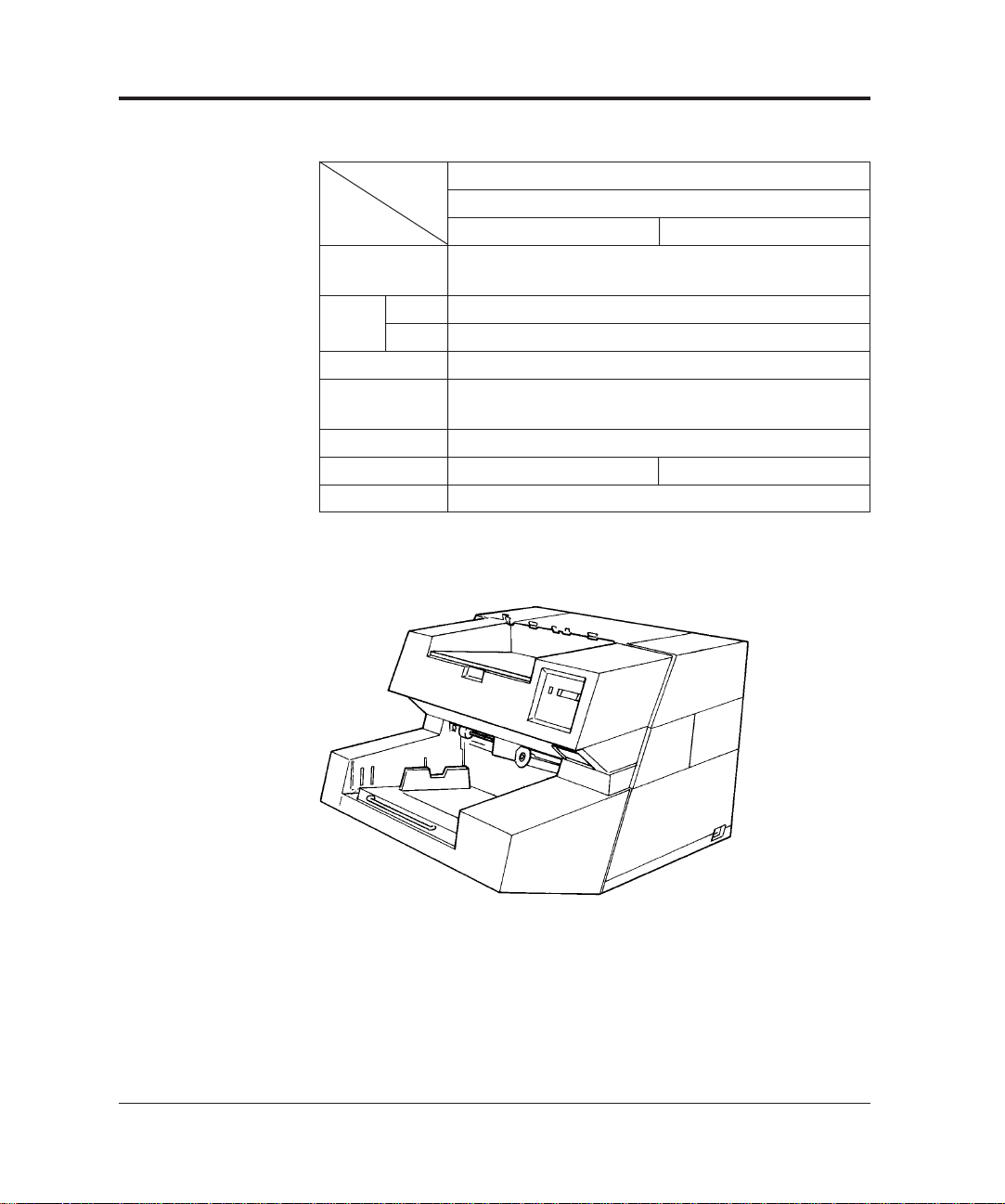
Table 1.2 Types of M3099EX
Type 1000 sheets hopper
with IPC2
Item 100V 200V
Maximum
document size
Scanning Simplex
Duplex
Hopper capacity 1000 sheets
Hight of
the Scanner
IPC2 (option) Installed
Input voltage 100V 200V
Appearance Figure 1.2
A3/Double letter
60 PPM (A4, 200dpi, portrate)
50 PPM (A4, 200dpi, portrate)
530 mm
Figure 1.1 500 sheets hopper type
1-2 M3099EX/EH OEM Manual
Page 15
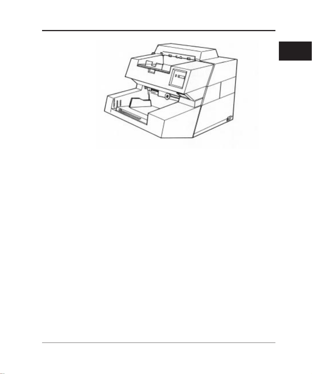
Figure 1.2 1000 sheets hopper type
OVERVIEW
M3099EX/EH OEM Manual 1-3
Page 16

Features
This scanner has the following features:
Duplex reading
Both sides of a document are read at the same time and their data
transferred serially.
Fast reading
This scanner can read documents at high speed: 80 sheets/min (A4,
200dpi) in the simplex reading mode and 60 sheets/min (A4,
200dpi) in the duplex reading mode by M3099EH.
Large-capacity hopper
Up to 1000 sheets (A4, 55 kg) can be loaded on the hopper by the
1000 sheets hopper type.
High-quality image
This scanner uses a compact optical system that provides sharper
focus. Furthermore, the use of new LSI chips produces finer images.
New image processing function
The error diffusion feature is provided as standard. Dithering or
error diffusion can be applied to those areas judged to be
photographs by automatic separation (image processing II option).
1-4 M3099EX/EH OEM Manual
Page 17
Configuration
This section provides configuration and components of the scanner.
Configuration of the scanner
This scanner can be divided into two major sections, mechanism and
control unit.
The mechanism unit consists of a hopper to load documents,
automatic document feeder, upper and lower transport units to
transport documents, a motor drive system, and an optical unit.
The control unit consists of an operator panel, a power supply, a
mechanism driver to drive and control the mechanism unit, an image
processing control, and an interface control.
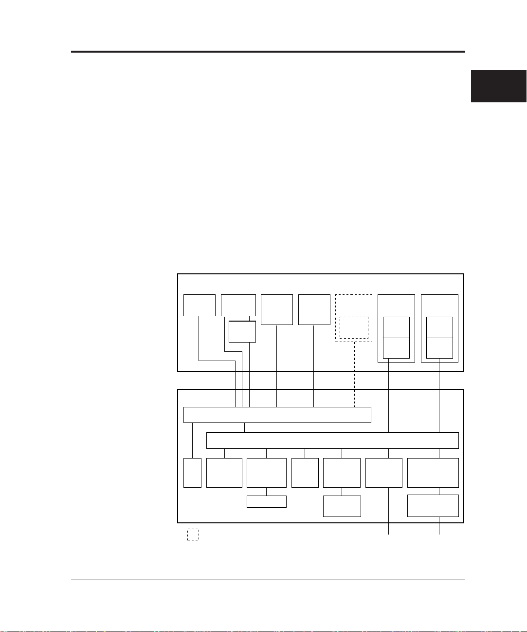
Figure 1.3 shows scanner configuration.
OVERVIEW
Mechanism unit
Transfer
system
Sensor Lamp,
(Front-side) (Back-side) (Back-side)
heater,
inverter
Sensor
board
Lamp,
heater,
inverter
Control unit
Mechanism driver
Fan Operator
panel
: Option
Back-side
reading
board
IPC-2 Extend
(Back-side)
IPC-2 Extend
(Front-side)
Figure 1.3 Scanner block diagram
Printer
Motherboard
memory
board
memory
(Front-side)
Optical
system
Printer
driver
CCD
driver
Video
circuit
Interface
board
RS-232C+VIDEO 100/200VAC
Optical
system
CCD
driver
Video
circuit
Power supply
(5V, 12V)
Power supply
(24V)
M3099EX/EH OEM Manual 1-5
Page 18
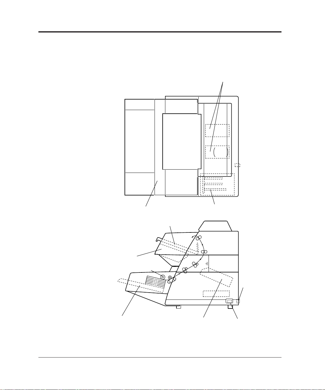
Arrangement of units
Power supply units
(+24V)
+5V
±12V
Control unitOperator panel
Stacker
Optical unit
(front-side)
Automatic document
feeder (ADF)
Hopper
Optical unit
(back-side)
Power switch
Power inlet
Figure 1.4 shows arrangement of these units.
1-6 M3099EX/EH OEM Manual
Figure 1.4 Arrangement of units
Page 19

Operation Overview
This section outlines the operations of the mechanism and control
units of the scanner.
Operation of the mechanism unit
The mechanism unit consists of two optical units (front and back
sides), a hopper and ADF, upper and lower transport units, a motor
drive system, and a stacker. Each optical unit consists of a CCD
image sensor, a lens, and mirrors. The hopper and ADF feeds
stacked documents and the upper and lower transport units transport
the documents. The motor drive system drives these units. The
stacker stores documents.
When the power is turned on, the lamps are lit and the scanner
waits until the light intensities of the lamps become stable. Once the
light intensities have become stable, the scanner is ready for a
command from the host machine.
A document is picked from the hopper and then ADF feeds a
document one by one. The document width is checked and
document top is detected.
The documents are counted, fed, and stacked on the stacker.
OVERVIEW
The lamps illuminate the document, and a lens focuses the images
on CCD for photoelectric conversion processing.
M3099EX/EH OEM Manual 1-7
Page 20
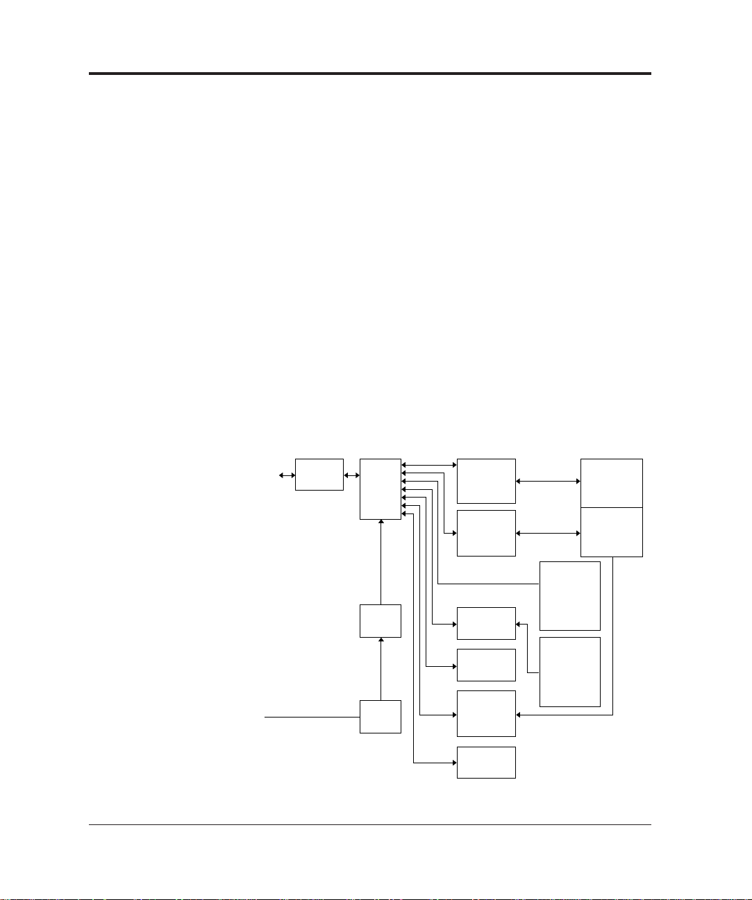
Operation of the control unit
The control unit consists of an operator panel, a power supply unit,
mechanism driver, an image processing control, and an interface
control.
This scanner has the following circuit configuration:
• Operator panel
• Control circuit (MPU)
• Video circuit (front-side/back-side)
• Interface circuit
• Duplex circuit (back-side)
• Motor driver circuit (including a stepper motor, a clutch driver)
• Power supply unit
• Image processing circuit (IPC II option)
• Memory board
Figure 1.5 shows control block diagram.
Host
machine
100 to 120 VAC
220 to 240 VAC
Interface
circuit
Control
circuit
(MPU )
Power
supply
Power
switch
Video
circuit
(front-side)
Video
circuit
(back-side)
Duplex
circuit
Memory
board
Motor
driver
circuit
Operator
panel
Mechanism
unit
ADF
MF
Image
processing
circuit II
(option)
(front-side)
Image
processing
circuit II
(option)
(back-side)
Figure 1.5 Control block diagram
1-8 M3099EX/EH OEM Manual
Page 21

Main control unit
This scanner is controlled by a 80C186 MPU. This scanner consists
of a ROM as a program area, internal registers, an external RAM as a
work area, gate arrays for the MPU peripheral and video circuits,
dither processing and γ conversion RAMs, and error diffusion.
Interface control
RS-232C and video interface
RS-232C interface
The RS-232C interface consists of an ACIA( 8251) and driver-receiver
ICs (145406).
Video interface
This scanner processes a document by the 256-step gray scale. Images
are processed in a way specified by the interface or the operator panel
and transferred serially in eight-bit units. Eight-bit data has V0 at the
left end and V7 at the right end and strobed by VCL.
HGATE ensures the validity of data in the main scanning and
VGATE for the subscanning.
OVERVIEW
The scanner status is basically reported by the RS-232C interface. An
equipment error is reported to the host computer by a FAIL signal in
case that RS-232C communication failed. See Chapter 3 for detailed
specifications of the interfaces.
Resolution
The basic resolution of this scanner is 200dpi. The resolution can be
changed to 240, 300, or 400dpi from the host computer or the
operator panel.
The resolution in the subscanning direction is achieved by changing
the document transport speed.
When the image processing circuit II (IPC II) option is installed, the
linear density is changed by setting the parameter to its internal circuit.
M3099EX/EH OEM Manual 1-9
Page 22

Video amplifier and driver section
This section consists of a CCD drive circuit, a video amplifier
circuit, a white-black level correction circuit, sensors, and also
control circuits for the stepping motor, heater, and lamps.
Image processing section
The IPC II option enables the following image processing functions:
• Automatic separation function (to read documents containing
characters and photographs)
• Inversion function
• Mirror image output function
• Outline extraction function
• Overlay function
• Smoothing, filtering, and noise removing
Power supplies
This scanner has two power supplies. Their output voltages are as
follows:
Power supply 1
• +5V: For logic circuits
• ±12V: For video amplifiers
Power supply 2
• 24V: For lamp, heater, and stepping motor drive
1-10 M3099EX/EH OEM Manual
Page 23

CHAPTER
2
General
SPECIFICATIONS
This chapter provides general, electrical, environmental, physical,
and option specifications.
Table 2.1 list general scanner specifications.
Table 2.1 General scanner specifications
Type
Item
Sensor
Scanning method
Document
size
Light source
Hopper/stacker
capacity
Gray scale (internal)
Output video
Scanning speed (A4,
200dpi, portrait)
Output density
Binarization and
halftone function
Interface
MAX.
MIN.
(64 g/m2)
Simplex
Duplex
500 sheets hopper 1000 sheets hopper
ADF
216 × 356 mm (A4/Letter/Legal) 297 × 432 mm (A3/Double letter)
Standard: 400, 300, 240, 200dpi (Horizontal
scanning and vertical scanning are independent.)
If the image processing II (IPC2) is installed: 50 to
400 dpi (Horizontal scanning and vertical scanning
are independent.)
Standard: Fixed binarization, dither, error diffusion
method. If the image processing II (IPC2) is
installed: Automatic separation, image emphasis,
outline extraction, mirror image, inversion,
simplified DTC. Dynamic threshold, smoothing,
filtering, nois removing.
RS-232C (Control signal) + Local (Video signal)
M3099EH M3099EX
1000 sheets hopper
CCD image sensor
(automatic document feeder)
76 × 63 mm (3" × 2.5")
Green fluorescent lamp
MAX. 500 MAX. 1000 MAX. 1000
sheets sheets sheets
256 steps
Binary/Halftone (64 levels)
80 PPM 60 PPM
60 PPM 50 PPM
& MF
(manual feeder)
SPECIFICATIONS
M3099EX/EH OEM Manual 2-1
Page 24

Electrical Specifications
Table 2.2 lists electrical specifications.
Table 2.2 Electrical specifications
Environmental Specifications
Item
Input power
Power consumption
Rush current
Momentary power failure
Leakage current
Dielectric strength
AC line noise
Heat capacity
Voltage
Phase
Frequency
Specification
100 to 120 VAC/220 to 240 VAC ±10%
Single-phase
50/60 Hz +2%, –4%
0.25 kVA or less
30 A or less
100%, 0.5 Hz
3.5 mA or less
DC 1.8 KV for one minute or more
(between FG and AC lines)
Voltage 1.2 KV pulse duration 5 µs
110 Kcal/H (440 BTU/H)
Table 2.3 lists environmental specifications.
Table 2.3 Environmental specifications
Item
Ambient
conditions
Shock
Stability
Acoustic noise
ESD
Device status
Temperature
Humidity
Specification
Operating
5 to 35°C
20 to 80%
(no condensation)
0.2 G less
5° or less
59 dBA or less
(ISO 7779)
8 KV or more
Not operating
–20 to 60°C
8 to 95%
(no condensation)
0.4 G or less
10° or less
50 dBA or less
(ISO 7779)
2-2 M3099EX/EH OEM Manual
Page 25
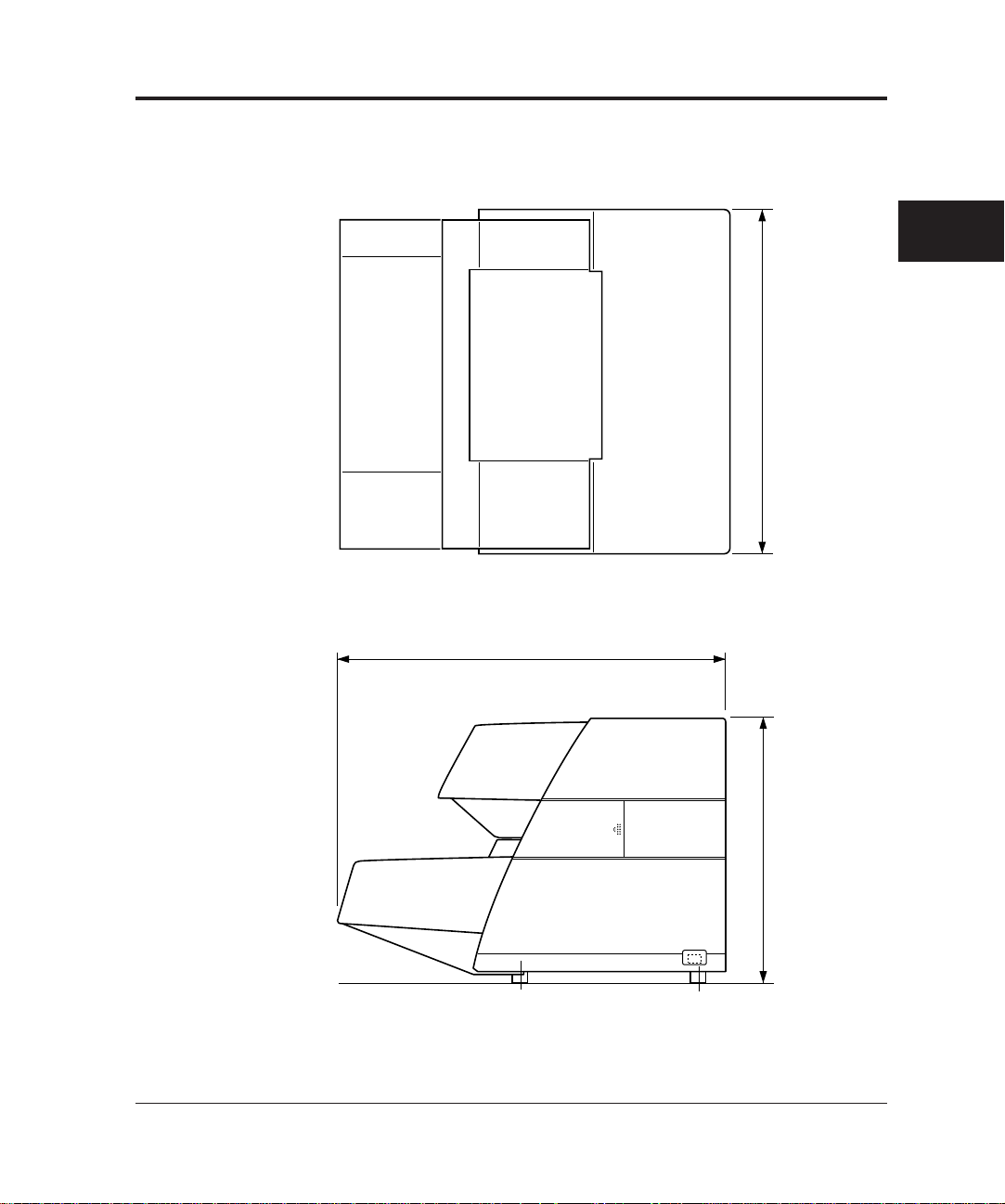
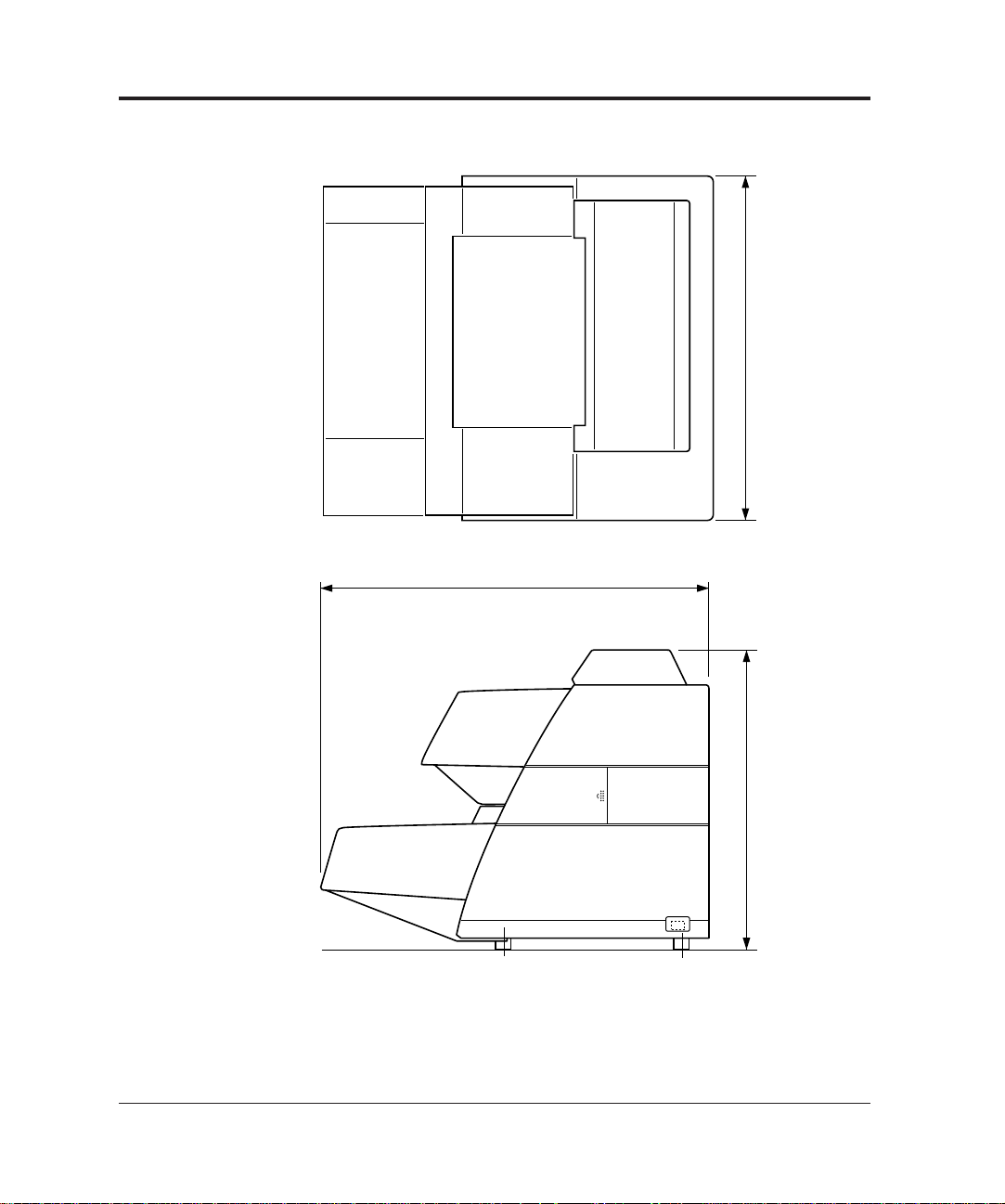
Physical Specifications
Figure 2.1 to Figure 2.2 show the scanner dimensions, Figure 2.3
shows scanner service areas. Table 2.4 lists physical specifications.
SPECIFICATIONS
610
680
470
(Unit: mm)
Figure 2.1 Dimensions of 500 sheets hopper type
M3099EX/EH OEM Manual 2-3
Page 26
680
610
530
(Unit: mm)
Figure 2.2 Dimensions of 1000 sheets hopper type
2-4 M3099EX/EH OEM Manual
Page 27
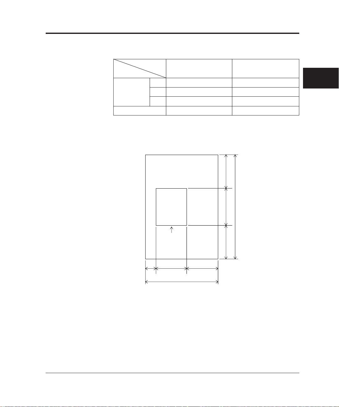
Table 2.4 Physical specifications
Type
Item
Dimensions
Weight
500 sheets hopper type 1000 sheets hopper type
Width
Depth
Height
610 mm 610 mm
680 mm 680 mm
470 mm 530 mm
55kg 65kg
SPECIFICATIONS
600680600
Scanner
F
200 610 600
1,390
1,860
F: Front
(Unit: mm)
Figure 2.3 Service areas
M3099EX/EH OEM Manual 2-5
Page 28

Option Specifications
Table 2.5 lists the scanner option specifications.
Table 2.5 Option specifications
Item
Endorser
Specification
CA01023-D004
Detail
Ink-jet
back-side print
max. 20 characters
Remark
2-6 M3099EX/EH OEM Manual
Page 29

CHAPTER
3
Control Interface
INTERFACE SPECIFICATIONS
This section describes the control interface between the host
computer and the scanner. For details of the interface, refer to the
EIA RS-232C standard.
Connection specifications
Item
Transmission system
Synchronization system
Data length
Stop bit
Data check
Data transfer rate
Maximum connection
Standard
Half-duplex
Start-stop
8 bits
1 bit
Odd parity check
1200, 2400, 4800, 9600 bps
5 m (16 ft.)
EIA RS-232C
0
Start bit
Specification
D1D
D2D3D
Remark
D6D
D
4
5
P
7
Stop
bit
Set by
EEPROM
on Interface
PCA
Default:
4800 bps
INTERFACE
SPECIFICATIONS
M3099EX/EH OEM Manual 3-1
Page 30
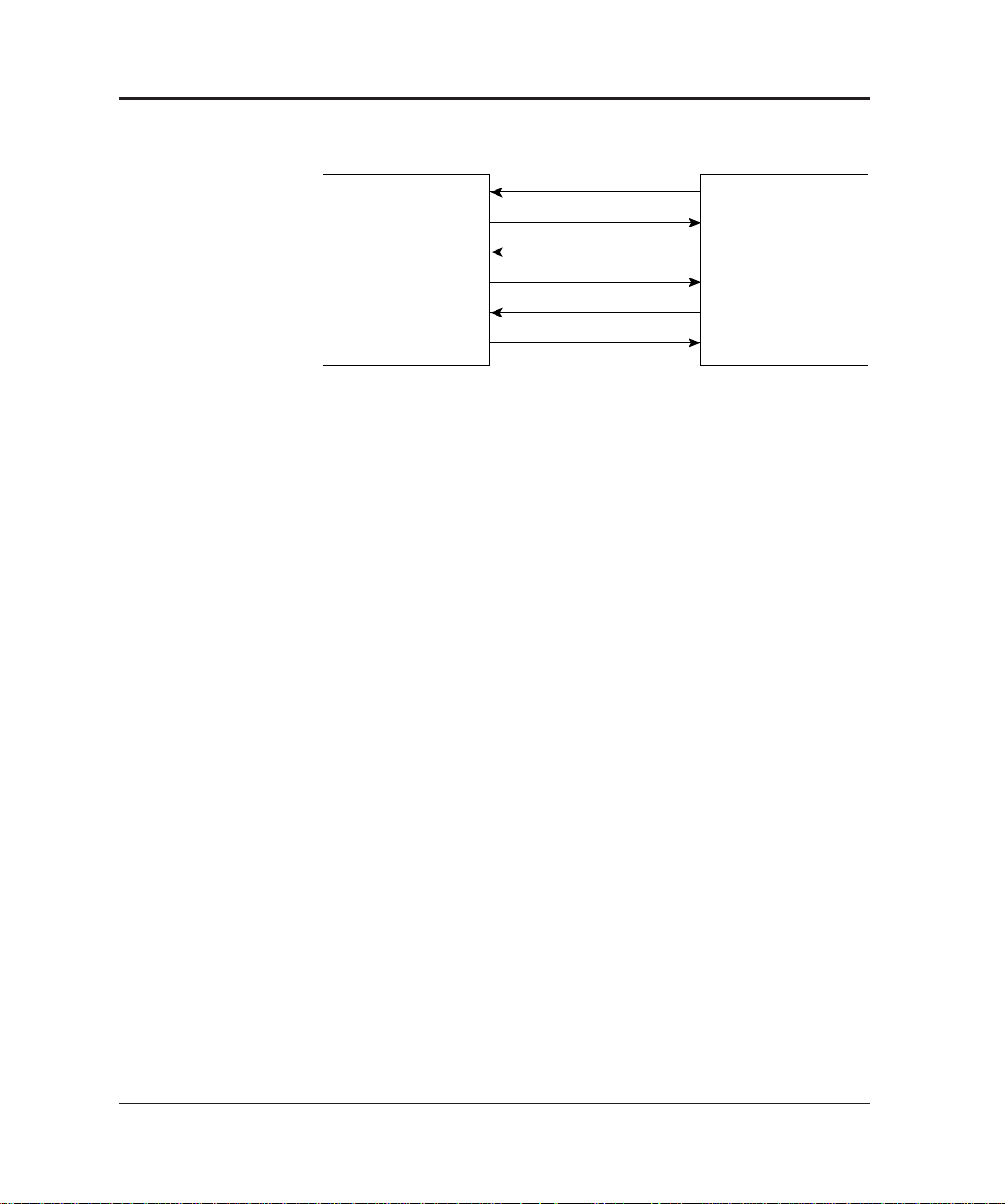
Control interface signals
T/D
R/D
RTS
CTS
DTR
DSR
Host computer Scanner
Figure 3.1 Control interface signal lines
Send data (T/D)
This signal is the response and acknowledge for the command sent
on the R/D line.
Received data (R/D)
This line sends the command and acknowledge for a response.
Send request (RTS)
This line sends a request to send a response and acknowledge for the
command.
Transmission enabled (CTS)
This line sends an acceptance of RTS signal.
Terminal ready (DTR)
This signal indicates that the scanner is ready for transmission and
reception.
This signal is set to off when the scanner is turned off, when the
scanner is initially checked after power on.
3-2 M3099EX/EH OEM Manual
Controller ready (DSR)
This signal indicates that the host computer is ready for transmission
and reception.
Page 31

Driver/receiver
• Driver: SN75188 or equivalent
• Receiver: SN75189 or equivalent
To determine the threshold level of the signal at the receiver, the
following circuit must be connected to the response control pins.
–12 V
20 kΩ
To response control pin
100 pF
0V
INTERFACE
SPECIFICATIONS
M3099EX/EH OEM Manual 3-3
Page 32

Timing
RTS
T/D
CTS
a
b
cd
a: +0 ms
b: +0 to 5 ms
c: +0 to 10 ms (more than 1 word length)
d: +0 ms
Scanner → Host computer (At transmission)
3-4 M3099EX/EH OEM Manual
Page 33

Video Interface
This section describes the video interface, which transfers the
scanning data from the scanner to the host computer.
Video interface signals
➤
➤
Host computer Scanner
➤
➤
➤
VCL
HGATE
VGATE
V0 ~ V7 (8 lines)
FAIL
Figure 3.2 Video interface signal lines
(1) VCL
This signal is a sampling clock for the video data V0 to V7.
(2) HGATE
This signal indicates that the main scanning video data is valid.
(3) VGATE
This signal indicates that the subscanning video data is valid.
(4) V0 to V7
INTERFACE
SPECIFICATIONS
These signal lines carry the scanning video data. Logical “0”
indicates a black dot.
(5) FAIL
This signal indicates that a device error (MPU ROM/RAM
error) has occured in the scanner.
M3099EX/EH OEM Manual 3-5
Page 34

Driver/receiver
Driver/receiver for standard connector and µ3096A21 connector.
(1) VCL
Scanner
side
MB463
(2) V0 to V7
MB463, or LS38
Host computer
+5 V
150 Ω
•
330 Ω
0V
1 kΩ
LS240, LS14,
or equivalent
+5 V
•
LS240, LS14,
or equivalent
HGATE, VGATE, FAIL
+5 V
1 kΩ
100 Ω
•
MB463, or LS38
3-6 M3099EX/EH OEM Manual
100 pF
•
LS240, LS14,
or equivalent
0 V
Page 35

Data transfer
Scanning video data is transferred to the host computer trough video
data signal line V0 to V7 in parallel synchronized with VCL.
Transfer sequence
Scanning is performed as sown in Figure 3.3, and the scanning data
is assigned to the video data signal as shown in Figure 3.4. The
scanning data is sent to the host computer in order of scanning.
Main scanning
Subscanning
Figure 3.3 Scanning direction
Main scanning
76543210765 076543210
765432107 012 76543210
INTERFACE
SPECIFICATIONS
Subscanning
7654321 4321076543210
7654321 456 321076543210
Notes:
1. “0” to “7” correspond to the video data signal V0 to V7 respectively.
2. The most significant bit (MSB) of each video data signal is read first.
Figure 3.4 Scanning data assignment
M3099EX/EH OEM Manual 3-7
Page 36

Effect in main scanning
HGATE
∇
VIDEO
X
➤
➤
Y
➤
The values of X, Y, and α are shown in Tables 3.1 and 3.2.
∇ : Reference point of main scanning.
Table 3.1 Transferred data length in main scanning (portrait mode)
Item
Document size
Offset dot
Double-letter* A3 * B4 * A4 B5 A5 LEGAL LETTER
X
12±12
↓↓↓↓
↓
↓↓↓↓
➤
➤
➤
↓↓
↓
↓↓↓↓
α
↓↓↓↓
9±9
8±8
6±6
4864
–
–
–
–
–
3648
–
2920
–
2432
–
Y
Transferred
400 dpi
data
Dummy dots
Offset dot
Transferred
300 dpi
data
Dummy dots
Offset dot
Transferred
240 dpi
data
Dummy dots
Offset dot
Transferred
200 dpi
data
Dummy dots
Note : 1. Data of dummy dots are sent as white.
2. Document size with * mark is available onl for M3099EX.
4400
α
X
Y
3304
α
X
Y
2640
α
X
Y
2200
α
4096
–
↓↓↓
3072
–
2464
–
2048
–
3456
–
2592
–
2080
–
1728
–
3456
–
2592
–
↓↓
2080
–
1728
–
2304
–
↓
1728
–
↓
1384
–
↓
1152
–
3456
3456
–
–
2592
2592
–
–
2080
2080
–
–
1728
1728
–
–
(Unit : lines)
3-8 M3099EX/EH OEM Manual
Page 37

Table 3.2 Transferred data length in main scanning (landscape mode)
Item
400 dpi
Document size
Offset dot
Transferred
data
Dummy dots
Double-letter A3 B4 A4 * B5 * A5 LEGAL LETTER *
X
Y
α
12±12
4680
–
↓↓
4080
–
↓
3312
–
12±12
–
–
–
4400
–
INTERFACE
SPECIFICATIONS
Offset dot
Transferred
300 dpi
data
Dummy dots
Offset dot
Transferred
240 dpi
data
Dummy dots
Offset dot
Transferred
200 dpi
data
Dummy dots
Note : 1. Data of dummy dots are sent as white.
2. Document size with * mark is available onl for M3099EX.
X
Y
α
X
Y
α
X
Y
α
Effect in subscanning
VGATE
∆
9±9
3512
–
8±8
2808
–
6±6
2344
–
3040
–
↓↓
2432
–
2024
–
↓
2480
–
↓
1984
–
↓
1656
–
9±9
–
3304
–
–
–
8±8
–
2640
–
–
–
6±6
–
2200
–
–
–
(Unit : lines)
VIDEO
X
➤
➤
Y
➤
➤
The values of X and Y are shown in Tables 3.3 and 3.4.
∇ : Reference point of subscanning.
M3099EX/EH OEM Manual 3-9
Page 38

Table 3.3 Transferred data length in subscanning (portrait mode)
Item
400 dpi
300 dpi
240 dpi
200 dpi
Document size
Offset dot
Transferred
data
Offset dot
Transferred
data
Offset dot
Transferred
datat
Offset dot
Transferred
data
Double-letter* A3 * B4 * A4 B5 A5 LEGAL LETTER
X
32
Y
6912
X
24
Y
5184
X
20
Y
4160
X
16
Y
3456
↓↓↓↓
6614
4961
3969
3307
↓
5732
↓↓↓
4300
3440
2886
↓↓↓↓
4677
3508
2806
2339
↓↓
4048
3036
↓↓
2429
2024
↓
3307
↓
2480
↓
1984
↓
1654
↓↓↓↓
5600
4200
3360
2800
↓↓↓↓
4400
3300
2640
2200
Note : 1. Document size with * mark is available only for M3099EX.
(Unit : lines)
2. The document size (VGATE) is set to off when the edge of
the document passes the scan position.
3-10 M3099EX/EH OEM Manual
Page 39

Table 3.4 Transferred data length in subscanning (landscape mode)
Item
400 dpi
300 dpi
240 dpi
200 dpi
Document size
Offset dot
Transferred
data
Dummy dots
Offset dot
Transferred
data
Dummy dots
Offset dot
Transferred
data
Dummy dots
Offset dot
Transferred
data
Dummy dots
Double-letter A3 B4 A4 * B5 * A5 LEGAL LETTER *
X
Y
32
3456
↓↓
3456
↓
2304
–
–
α
2592
↓
1728
–
–
X
Y
24
2592
α
X
Y
20
2080
↓↓
2080
1384
–
↓
–
α
1728
↓
1152
–
–
X
Y
16
1728
α
32
3456
INTERFACE
SPECIFICATIONS
24
2592
20
2080
16
1728
Note : 1. Document size with * mark is available only for M3099EX.
(Unit : lines)
2. The document size (VGATE) is set to off when the edge of
the document passes the scan position.
M3099EX/EH OEM Manual 3-11
Page 40

Timing
➤
➤
➤
➤
➤
➤
➤
➤
VCL
t
2
t
1
t
3
t
4
V0 to V7
VCL and V0 to V7
VCL and HGATE
HGATE
VCL
t
5
➤➤➤
Note : VCL is not output when HGATE is off.
~
~
~
~
t
6
➤
HGATE and VGATE
HGATE
VGATE
t
7
➤➤➤
The values of t1 to t8 is shown in Table 3.5.
Note : HGATE is always output.
~
~
~
~
t
8
➤
3-12 M3099EX/EH OEM Manual
Page 41

MIN TYP MAX
t1
t2
t3
t4
t5
t6
t7
t8
700
500
500
100
100
100
100
2000
800
600
600
200
200
200
200
*1
900
700
700
300
300
300
300
[Standard transfer : front-side]
Unit : ns
MIN TYP MAX
t1
t2
t3
t4
t5
t6
t7
t8
300
100
100
100
100
100
100
2000
400
200
200
200
200
200
200
*1
500
300
300
300
300
300
300
[Fast transfer : back-side]
Unit : ns
Table 3.5 Timing specification at binary output
Notes: 1. Timing marked with * varies according to the scanning
area.
INTERFACE
SPECIFICATIONS
M3099EX/EH OEM Manual 3-13
Page 42

Command and Response
Basic command/response sequence
Data is transmitted between the host computer and the image
scanner in the form of commands and responses. Figure 3.5 shows
the basic command/response sequence.
Host computer
Command
Completion of
command transmission
Command
retransmission
(only twice)
Abnormal
reception
Normal reception
ACK
Reception
error
Scanner
Abnormal
reception
Normal reception
ACK
Reception
error
• Command
processing
• Operation
Response
Response
transmission end
Response
retransmission
(only twice)
Figure 3.5 Basic command/response sequence
3-14 M3099EX/EH OEM Manual
Page 43

Notes:
1. Abnormal reception means that a parity error, framing
error, overrun error, or count error has occurred.
2. Command or response transmission is retried only twice.
3. Upon reception, a command or response is checked for
transmission errors. When the check result has no
problem, ACK is returned immediately to the originating
source. When the check result has problem, data other
than ACK is returned after all data has been received.
Response data
ACK
(Acknowledge)
Parity error
Framing error
Overrun error
Count error
Reception error
4. The originating source of the command/response
monitors the response from the receiving side. ACK
indicates that command/response transmission is
completed.
Details
A command or response has been
received without an error.
A parity error has been detected in
received data.
A framing error or an overrun error has
been detected in received data.
The byte count for the command or
response does not match the number of
bytes transferred.
INTERFACE
SPECIFICATIONS
Code (Hex)
X 'FF'
X'80'
X '81'
X '82'
Reception error causes the command/response to be
transmitted again. The transmission is returned only
twice. After that, the scanner waits for a new command.
5. Response data such as ACK must be retried to the
originating source within 0.5 second.
6. The interval between words in the data stream must be no
more than 10 ms.
M3099EX/EH OEM Manual 3-15
Page 44

Command/response format
The command/response format is as follows.
TEXT Additional fieldCNT CMD/RPS
CNT (count) field
The total number of bytes in the command/response to be
transmitted is represented.
CMD/RPS field
A command or response code is indicated.
TEXT field
Additional information for a command/response, called control or
device information, is indicated.
Additional field
In some commands, additional field exists next to TEXT field.
3-16 M3099EX/EH OEM Manual
Page 45

Command
Commands sent from the host computer to the scanner are as listed
in Table 3.6. The scanner commands are as follows:
Table 3.6 Commands
Command
name
Command
code
Details
INTERFACE
SPECIFICATIONS
CLEAR
CONTROL
IMAGE
CONTROL
PRINT
CONTROL
START
READ
SENSE
RETURN
SENSE
IMAGE
MODE
SENSE
SEND
DITHER 1
SEND
DITHER 2
SEND DATA
INQUIRY
*1: This command can be transmitted only when the image processing
option is connected.
*2: This command can be transmitted only when the endorser option is
connected.
44
58
5A
5E
53
54
41
42
43
46
47
48
40
This command initializes the scanner.
This command can be issued at any time.
This command sets the operation mode of
the scanner and the operation mode in the
main window.
This command sets the image processing
mode of the scanner. (*1)
This command instructs how to print to the
manuscript. (*2)
This command reports the size of a
document to be read.
This command starts reading. The scanner
starts reading according to the operation
mode set previously.
This command requests a status report.
This command requests a status report on
the return of the flatbed read.
This command requests a status report of
the image processing mode of each main
window and the number of pixels (in units
of a byte) per line in the X- direction.
This command transfers the dither and
overlay patterns.
This command transfers the dither, γ curve,
or overlay patterns.
Transfers print pattern and data items. (*2)
This command requests a device
information report.
M3099EX/EH OEM Manual 3-17
Page 46

3
CLEAR command details
Control register start
number.
Image control register start
number.
Print information I
IMAGE MODE SENSE
command details
Dither or overlay pattern
number.
X'00'
Print information III
Command
name
CLEAR
CONTROL
IMAGE
CONTROL
PRINT
CONTROL
START
READ
SENSE
RETURN
SENSE
IMAGE
MODE
SENSE
INQUIRY
SEND
DITHER 1
SEND
DITHER 2
SEND DATA
1
X'03'
X'0X'
X'0X'
X'0B'
X'02'
X'02'
X'02'
X'02'
X'03'
X'02'
X'43'
X'05'
X'XX'
2
X'44'
X'58'
X'5A'
X'5E'
X'53'
X'54'
X'41'
X'42'
X'43'
X'40'
X'46'
X'47'
X'48'
4 or later
Control register
Image control register
Byte 4: Print information II
Byte 5 and 6: Print position X
Byte 7 and 8: Print position Y
Byte 9: Number counter
method
Byte 10 and 11: Number initial
value
Dither or overlay pattern
64 bytes or more
Byte 4 and 5: CNT
Byte 6: Pattern ID
Byte 7 or later: Dither, overlay
or γ curve data
Printing data
3-18 M3099EX/EH OEM Manual
Page 47

CLEAR command
b7 b0
00: POWER ON CLEAR
This command resets the system to the
power-on status.
01: Control register clear
This command intitializes the operation
mode, image processing mode, and
subwindow mode. (*1)
10: Reading stop
This command stops operation during
(VGATE OFF, return) and ejects any
documents remaining in the ADF.
If this command is received after the frontside is reading ends, the scanner is placed
in wait state.
*1: If a CONTROL REGISTER CLEAR command is issued after the
READ command is sent to the scanner but before the Read
Complete
is recieved from the scanner, a command sequence error occur.
Note: "Ready" is the response when this command ends normally.
This command initializes the scanner and can be issued at any time.
b7 b0
b7 b0
CNT
(X‘03’)
CLEAR command details
CMD
(X‘44’)
b7 b0
CLEAR
command
INTERFACE
SPECIFICATIONS
M3099EX/EH OEM Manual 3-19
Page 48

CONTROL command
CNT (X'0X') CMD (X'58')
Control register No.
Control register
b7
b0 b7 b0 b7 b0 b7 b0
Control register No.
#0
#1
#2
#0
#XX
#21
#0
#XX
#21
EXT. control reg.
EXT. control reg.
EXT. control reg.
Control reg. A
Control reg. A
Control reg. B
Control reg. B
10
00
01
11
b7 b6
b7 b6
b7 b6
b7 b6
Selection
of register
Undefined
Front-side
reading
Back-side
reading
REG No.
This command sets the scanner to the operation mode.
Selection of control register
This scanner has an additional function to select control register,
using bits 6 and 7 of byte 3 of the CONTROL command supported
by the existing devices (M3093E, M3096E+, and M3097E).
• Front-side reading or front-side and back-side reading control
register specification
• Back-side reading control register specification
• Extended control register specification
The registers are specified as follows:
3-20 M3099EX/EH OEM Manual
Hereafter, a control register for front-side reading (compatible with
the exiting devices) is called control register A. A control register for
back-side reading is called control register B.
Page 49

Extend control register
Extend control register #0
b7 b0
00#0
Transfer mode (back-side) (*1)
Reading mode specification
0××: Set from the operator panel
100: Front-side reading
11×: Duplex reading
*1: See the 3-23 page.
INTERFACE
SPECIFICATIONS
[00h]
This function specifies how image data in the
back-side memory should be transferred.
000: Transfer mode 0
001: Transfer mode 1
010: Transfer mode 2
011: Transfer mode 3
1××: Reserved
M3099EX/EH OEM Manual 3-21
Page 50

Extend control register #1
This register is not supported.
b7 b0
#1
00
000000
[00h]
X'00' is set when the power is turned on or when a CLEAR
command is issued for initialization.
3-22 M3099EX/EH OEM Manual
Page 51

[Data transfer mode]
Transfer mode Front-side Back-side Ext
Mode 0
Mode 1
Mode 2
C
A
Main
Sub
BD
C
Main
Sub
DB
C
Main
Not supported
DB
C
Not supported
DB
Main
Sub
Sub
A
INTERFACE
SPECIFICATIONS
A
Mirror
A
Mode 3
C
A
Mirror
Not supported
Sub
DB
Main
: Scanning reference position
M3099EX/EH OEM Manual 3-23
Page 52

#2
b7 b0
[00h]
Transfer rate (front-side)
Transfer rate (back-side)
0×××: Depending on devices (800 ns)
1000: Undefined
1001: 800 ns
1010: Undefined
1011: Undefined
1100: Undefined
1101: Undefined
1110: Undefined
1111: Undefined
•This register specifies the front-side and back-side image data
transfer rates.
0×××: Depending on devices
(800 /400ns change by EEPROM)
1000: Undefined
1001: 800 ns
1010: 400 ns
1011: Undefined
1100: Undefined
1101: Undefined
1110: Undefined
1111: Undefined
Extend control register #2
3-24 M3099EX/EH OEM Manual
Page 53

Extend control register #3
#3 00 000000
b7 b0
[00h]
X'00' is set when the power is turned on
or when a CLEAR command is issued
for initialization
This register is not supported.
INTERFACE
SPECIFICATIONS
M3099EX/EH OEM Manual 3-25
Page 54

Control register A#0
X'00' is set when the power is turned on or when a CLEAR
command is issued for initialization.
b7 b0
A#0 0 0 0
Scanning resolution
0×××: Set from the operator panel
1000: 400 dpi
1001: 300 dpi
1010: 240 dpi
1011: 200 dpi
1100:
1101:
Not defined
1110:
1111:
Specified start of reading (*2)
0: Operation panel (*1)
1: Host computer
*1: When the start of reading is specified from the operator panel,
the Ready lamp lights at reception of a START command.
*2 If the manual mode is selected at the operator panel, reading
actually starts when a document is loaded on the scanner.
Control register B#0
b7 b0
B#0
00000000
3-26 M3099EX/EH OEM Manual
Page 55

Control register A#1
Control register B#1
X’00' is set when the power is turned on or when a CLEAR
command is issued for initialization.
b7 b0
A#1
B#1
Density
00×××: Set from the operator panel
01000: Light
01001:
01010: Somewhat light
01011:
01100: Normal
01101:
01110: Somewhat dark
01111: Dark
1××××: Dynamic threshold (*1)
Linedrawing/photograph
0×: Set from the operator panel
10: Linedrawing (*2)
11: Photograph (*2)
*1: This function is valid for image processing circuit (IPC II) option.
When the IPC II option is installed and these bits indicate IXXXX, the
scanner applies the DTC function, and the function of the image control
register are not operated.
INTERFACE
SPECIFICATIONS
Darken more
and more
(*3)
*2 The scanning speed of ADF (sheets/min) in linedrawing mode is different
from that of photograph mode.
*3: When the control resister #19, bit 0 is "0", eight types density are selectable
by control register #1, bit 3 to 0.
And when the control register #19, bit 0 is "1", 256 types density are
sellectable by the control register #20.
M3099EX/EH OEM Manual 3-27
Page 56

b7 b0
*2: Dithered or Error diffusion are selected by control register #19.
000:
001:
010:
011:
100:
101:
110:
111:
Dither pattern No. specification
Built-in/Download
0: Built-in
1: Download
A#2
B#2
00
Specifies halftone
0×: Set from the operator panel
10: Not dithered
11: Dithered or Error diffusion (*2)
• When the built-in pattern is used, the density information shown in the
control register #1 is valid.
• Four patterns (000 to 011) are valid when the built-in pattern is selected.
• When the download pattern is used, the density information shown in
control register #1 is invalid.
• Eight patterns (000 to 111) is valid when the download pattern is
*1:
(*1)
Control register A#2
Control register B#2
X’00' is set when power is turned on or when a CLEAR command
issued for initialization.
3-28 M3099EX/EH OEM Manual
Page 57

Control register A#3
Control register B#3
X’A6' is set when power is turned on or when a CLEAR command is
issued for initialization.
• This register is valid when the IPC II option is installed.
b7 b0
A#3
B#3
DTC
Threshold curve
000: Light
001:
010:
011:
100:
101: Dark
110: Dark
111: Light
γ curve
00: Character recognition 1
01: Character recognition 2
10: Dark image
11: Equalized splitting
For OCR
Daken more
and more
For image scanner
INTERFACE
SPECIFICATIONS
Smoothing mode
00: For OCR
01: For image scanner
10:
Not defined
11:
Filtering
0: Ball-point pen mode
1: Ordinary mode
M3099EX/EH OEM Manual 3-29
Page 58

Control register A#4
Control register B#4
X’20' is set when power is turned on or when a CLEAR command is
issued for initialization.
• This register is valid when the IPC II option is installed.
b7 b0
A#4
B#4
00
(Dynamic threshold mode setting)
Binary data when the threshold equals
video data to be binary-coded. (*1)
0: Output binary data is "1". (Black)
1: Output binary data is "0". (White)
Noise removing of 2 × 2 matrix
0: OFF
1: ON
Noise removing of 3 × 3 matrix
0: OFF
1: ON
Noise removing of 4 × 4 matrix
0: OFF
1: ON
Noise removing of 5 × 5 matrix
0: OFF
1: ON
Enables the noise removing bits
(bits 1-4 when this bit is active).
0: ON
1: OFF
*1: When this bit is "0", the output video data is black if the
gradation of the video data is equal to or larger than threshold.
When this bit is "1", the output video data is white if the
gradation of video data is equal to or larger than threshold.
3-30 M3099EX/EH OEM Manual
Page 59

Control register A#5
X'00' is set when the power is turned on or when a CLEAR
command is issued for initialization. Default document size depends
on the EEPROM setting.
b7 b0
A#5
Standard document size
0000: A0
0001: A1
0010: A2
0011: A3 (Defined only M3099EX)
0100: A4
0101: A5
0110: Double-letter (Defined only M3099EX)
0111: Letter
1000: B0
1001: B1
1010: B2
1011: B3
1100: B4 (Defined only M3099EX)
1101: B5
1110:
1111: Legal
Specifies a vertical or horizontal direction
0: Portrait
1: Landscape
Picking
0: Not specified
1: Specified
Document selection
00: Set from the operator panel
01: Depends on setting from the operator
panel or the size detector of the ADF
10: Depends on the value of the standard
document size setting register.
Not defined
Not defined
Not defined
INTERFACE
SPECIFICATIONS
M3099EX/EH OEM Manual 3-31
Page 60

Control register B#5
B #5
00
b7 b0
Picking
0: Invalid
1: Valid
00 00 0
X’00' is set when the power is turned on or when a CLEAR
command is issued for initialization.
Control register A#6 to #9
Control register B#6 to #9
Not specified for this scanner.
NONSTANDARD DOCUMENT SIZE SETTING REGIS
3-32 M3099EX/EH OEM Manual
Page 61

Control register A#10 to #17
Control register B#10 to #17
Picking area (main window) setting register
#10
b7 b0
#11
b7 b0
LSBMSB MSB LSB MSB LSB MSB LSB
Picking in main scanning
*1
#12
b7 b0
Y1
Y2
#13
b7 b0
b7 b0
Document surface
#14
X2X1
Picking
area
#15
b0
b7
Picking in subscanning
#16
b7
Upper edge
▲
of document
b0
#17
b7
b0
Y2Y1X2X1
INTERFACE
SPECIFICATIONS
▲
Left edge of document
Operation error occurs when the values of X1 + X2 [(#10, #11) +
(#12, #13)] and Y1 + Y2 [(#14, #15) + (#16, #17)] area more than
the values shown below.
Scanner
M3099EX
M3099EH
X1 + X2
4864
3456
M3099EX/EH OEM Manual 3-33
Y1 + Y2
6912
6912
Page 62

• These values must be specified in binary in unit of 1/400-inch.
Reference point
Document
board
Area to be scanned
Front side of scanner
A
B
Note: 1. When the picking is specified, only a specified area of the
document is read. However, when the ADF is used, and
the document length is shorter than the specified area,
read operation is stopped at the edge of document.
2. When the specified area is larger than the double-letter
size, read area specification error occurs.
3. When the jam detection bit (control register #2) is "1", a
setting of Y2 is ignored.
Picking is specified when the scanner is required to read a special area
as shown below.
Picking is applied when bit 5 the control register #5 is "1" and the
address of points A and B is specified in the control registers #10 to
#17.
REG.
CNT CMD
REG.
No.
[Example]
or
CMDCNT
Note: When these registers are specified, four consecutive registers
(#10 to #13 or #14 to #17) must be specified.
3-34 M3099EX/EH OEM Manual
#10 #11 #12 #13
No.
(#14) (#15) (#16) (#17)
#17#16#15#14#13#12#11#10
Page 63

Control register A#18
Control register B#18
X”00" is set when the power is turned on or when a CLEAR
command is issued for initialization.
• This register reserved for future.
b7 b0
INTERFACE
SPECIFICATIONS
A #19
B #19
A #18
B #18
00 00000
0
Control register A#19
Control register B#19
X’00' is set when the power is turned on or when a CLEAR
command is issued for initialization.
b7 b0
00
Read density specification
0: 8 steps (Control register #1 is valid.)
1: 256 steps (Control register #20 is valid.)
Halftone processing method specification
0: Dithering
1: Error diffusion
γ pattern number specification (*1)
0 0 0 : Normal
0 0 1 : Soft
0 1 0 : Sharp
0 1 1
1 0 0 : Three types (0 to 2) if the built-in
1 0 1 patterns are valid.
1 1 0 : Eight types (0 to 7) if the downloading
1 1 1 is enabled.
Download/built-in γ patterns
0: The patterns built into the device are valid.
1: The download patterns are valid.
*1: If the built-in patterns are valid, 0 to 2 ('000' to '010') can be
selected.
M3099EX/EH OEM Manual 3-35
Page 64

Control register A#20
Control register B#20
X’00' is set when the power is turned on or when a CLEAR
command is issued for initialization.
b7 b0
A #20
B #20
Read density
(256-step selection) (*1)
X'00': Default (same as for X'80')
X'01': Light
X'FF': Dark
*1: This register is valid if bit 0 control register #19 is 1.
3-36 M3099EX/EH OEM Manual
Page 65

Control register A#21
Control register B#21
X'00' is set when the power is turned on or when a CLEAR
command is issued for initialization.
A #21
B #21
b7 b0
INTERFACE
SPECIFICATIONS
Contrast specification
X'00': Default (same as for X'80')
X'01': Lowest contrast
X'80': Normal
X'FF': Highest contrast
M3099EX/EH OEM Manual 3-37
Page 66

IMAGE CONTROL command
This command sets the scanner to the operation mode of the image
processing circuit.
Byte 1
CNT
X'0X'
(Byte 3)
Byte 2
CMD
X'5A'
Byte 3
TEXT
Image control
register start number
b7 b0
0
b6
0
Selects image control register A (front-side)
1
Selects image control register B (back-side)
Description
Byte 4
or later
Image control
register
Image control register No.
Front-side/back-side select
Note: If this command is sent to the scanner without image
processing option (IPC II), the scanner sends "Operation
error" as response.
3-38 M3099EX/EH OEM Manual
Page 67

Image control register
When the image processing option (IPC II) is connected, the
following image processing can be excuted. This register sets the
image processing mode.
– Image area automatic separation function (simultaneous reading
or characters and photographs)
– Inversion function (black/white conversion)
– Mirror image output function (right/left conversion)
– Image emphasis, outline extraction function
– Overlay function
– Simplified dynamic threshold.
– Zooming function ranging from 25% to 100% in 1%
increments.
Image control register A#0, B#0
X’00' is set when the power is turned on or when a CLEAR
command is issued for initialization.
b7 b0
#0
00 00000
0
This register must be sent before setting the image control registers
#1 to #8.
INTERFACE
SPECIFICATIONS
M3099EX/EH OEM Manual 3-39
Page 68

Image control register A#1, B#1
X”00" is set when the power is turned on or when a CLEAR
command is issued for initialization.
b7 b0
#1
00 0
Automatic separation specification (*1)
0 x : Set from the operator panel (*2)
1 0 : Automatic separation is not done.
1 1 : Automatic speparation
Conversion mode specification
0 x x : Not operation
1 0 0 : Not provided with white/black conversion.
Not provided with right/left conversion.
1 0 1 : Not provided with white/black conversion.
Provided with right/left conversion.
1 1 0 : Provided with white/black conversion.
Not provided with right/left conversion.
1 1 1 : Provided with white/black conversion.
Provided with right/left conversion.
Note: Image control registers #1 to #3 must be sent in one sequence.
One of automatic separation, image emphasis, outline extract,
overlay can be specified.
*1: Halftone specification (control register #2) is invalid in the
automatic separation mode. However, halftone processing
(dither or error diffusion) for photo area follows control register
#19, and the dither pattern follows control register #2.
*2: When automatic separation specification is based on operator
panel, the bit 7 of image control register #2 and the bit 3 of
image control register #3 must be set to '0'.
3-40 M3099EX/EH OEM Manual
Page 69

b7 b0
Sharpness control (image emphasis)
0 0 0 : Normal
0 0 1 : Emphasis, large Sharp
0 1 0 : Emphasis, middle
0 1 1 : Emphasis, small
1 x x : Smoothing Soft
Outline extraction control
0 0 : Outline extract
0 1 :
1 0 :
1 1 :
Sharpness, outline extraction specification
0 x x : Not operation
1 0 0 : Not operation
1 0 1 : Enables sharpness control.
1 1 0 : Enables outline extraction.
1 1 1 : Not defined
#2
Not defined
Image control register A#2, B#2
X’00' is set when the power is turned on or when a CLEAR
command state is issued for initialization.
INTERFACE
SPECIFICATIONS
M3099EX/EH OEM Manual 3-41
Page 70

b7 b0
Overlay specification (*1)
0 x : Not operation
1 0 : Not overlay
1 1 : Overlay
Overlay mode number specification
0 0 0
0 0 1
0 1 0
0 1 1
1 0 0
1 0 1
1 1 0
1 1 1
Download/built-in overlay pattern
0 : Built-in pattern valid
1 : Download pattern valid
#3
00
(*2)
Image control register A#3, B#3
X’00' is set when the power is turned on or when a CLEAR
command is issued for initialization.
*1: When dither or error diffusion processing is valid by the control
register #2 or operator panel, overlay is not performed even if it
3-42 M3099EX/EH OEM Manual
is valid by this register.
*2: This scanner has six patterns as built-in overlay pattern. ("000"
to "101")
Eight patterns can be registered as download pattern. ("000" to
"111")
The bits 4 to 7 is valid when the overlay specification is valid.
Page 71

Built-in overlay pattern
00
00
00
00
00
00
00
00
FF
FF
FF
FF
00
00
00
00
FF
FF
FF
FF
No. 0 Horizontal lines 00
00
00
00
00
00
00
00
00
00
00
00
00
FF
FF
FF
FF
FF
FF
FF
FF
FF
FF
FF
FF
FF
FF
FF
FF
00
00
00
FF
FF
FF
FF
00
00
00
00
FF
FF
FF
FF
INTERFACE
SPECIFICATIONS
No. 1 Vertical lines
No. 2 Angled pattern
00
00
00
00
00
00
00
00
FF
FF
00
00
00
00
FF
FF
00
00
00
00
00
00
00
00
FF
FF
FF
00
00
00
00
FF
00
00
00
00
00
00
00
00
FF
FF
FF
FF
00
00
00
00
00
00
00
00
00
00
00
00
00
FF
FF
FF
FF
00
00
00
FF
FF
FF
FF
FF
FF
FF
FF
00
00
FF
FF
FF
FF
00
00
FF
FF
FF
FF
FF
FF
FF
FF
00
00
00
FF
FF
FF
FF
00
FF
FF
FF
FF
FF
FF
FF
FF
00
00
00
00
FF
FF
FF
FF
FF
FF
FF
FF
FF
FF
FF
FF
FF
00
00
00
00
FF
FF
FF
M3099EX/EH OEM Manual 3-43
Page 72

FF
FF
FF
FF
00
00
00
00
00
00
00
00
FF
FF
FF
FF
00
00
00
00
FF
FF
FF
FF
00
00
00
00
FF
FF
FF
FF
No. 3 Dots pattern
00
00
00
00
FF
FF
FF
FF
FF
00
00
00
00
00
00
00
FF
FF
00
00
00
00
00
00
FF
FF
FF
00
00
00
00
00
FF
FF
FF
FF
00
00
00
00
FF
FF
FF
FF
FF
00
00
00
FF
FF
FF
FF
FF
FF
00
00
FF
FF
FF
FF
FF
FF
FF
FF
No. 4 Triangle pattern
FF
FF
FF
FF
FF
FF
FF
00
00
00
00
00
00
00
00
00
00
00
00
00
00
00
00
00
00
00
FF
FF
FF
FF
00
00
00
00
FF
FF
FF
FF
00
00
00
00
FF
FF
FF
FF
00
00
00
00
FF
FF
FF
FF
00
00
00
00
00
00
00
00
00
00
No. 5 Lattice pattern
00
00
00
00
00
00
00
00
FF
FF
FF
FF
00
00
00
00
FF
FF
FF
FF
00
00
00
00
FF
FF
FF
FF
00
00
00
00
3-44 M3099EX/EH OEM Manual
Page 73

Image control register A#4, B#4
b7 b0
Simplified dynamic threshold specification
0 x : Not operation
1 0 : Simplified DTC invalid
1 1 : Simplified DTC valid
Simplified DTC mode number specification
0 0 0 : Default
0 0 1 : Small
0 1 0 :
0 1 1 :
1 0 0 :
1 0 1 :
1 1 0 :
1 1 1 : Large
#4
00
Variance
rate of
threshold
level
X’00' is set when the power is turned on or when a CLEAR
command is issued for initialization.
INTERFACE
SPECIFICATIONS
M3099EX/EH OEM Manual 3-45
Eight parameter (000 to 111) can be specified as variance rate.
Page 74

Image control register A#5 to #8
X’0864' is set when the power is turned on or when a CLEAR
command is issued for initialization.
b7 b0b7 b0
#5
000010
#6
Magnification/vertical magnification
(when each direction zooming is valid)
0 0 0 0 1 1 0 0 1 : 25%
to to
0 0 1 1 0 0 1 0 0 : 100%
Vertical/horizontal
zooming specification (*2)
0 : Same magnification for both direction
1 : Different magnification for each direction
(*1)
*1: Register A#5, #6, #7, and #8 must be sent consecutively.
*2: When the vertical/horizontal zooming specification is set to "0",
the horizontal and vertical magnification is indicated. When this
specification is set to "1", vertical magnification is specified at bit
0 of the register A#5 and at all bits of the register A#6.
Example
How to calculate the output resolution:
• Control register #1 is X'0B' (200 dpi)
• Image control register A#5 and A#6 are X '0819' (25%)
• Output resolution = 200 dpi × 0.25 = 50 dpi.
3-46 M3099EX/EH OEM Manual
Page 75

X'0000' is set when the power is turned on or when a CLEAR
command is issued for initialization.
b7 b0b7 b0
#7
000000
#8
0
Horizontal magnification
(When each direction zooming is valid)
0 0 0 0 1 1 0 0 1 : 25%
to to
0 0 1 1 0 0 1 0 0 : 100% (*2)
(*1)
*1: Magnification is valid only when the horizontal/vertical zooming
specification (bit 1 of the register A#5) is set to "1".
*2: Document magnification has the following limitations:
Maximum main scanning data: 608 bytes/line
A × (B/400) × (C/100)
8
608 (bytes)≤
A: Main scan width (unit: number of pixels when
scanned at 400 dpi)
B: Basic resolution (set from operator panel or control
register #0: 200, 240, 300, 400 dpi)
C: Horizontal magnification (25 to 100%)
INTERFACE
SPECIFICATIONS
This expression is rounded up to the integer.
Image control register B#5 to #8
Since these registers are not supported, specify X’08000000'.
M3099EX/EH OEM Manual 3-47
Page 76

PRINT CONTROL command
b7 b0
Command specification
method
0 0 : Parallel processing
(read + print)
Print mode
0X: Depends on the operator panel specification.
10: OFF
11: ON
0000
b7
b0b7 b0b7 b0b7 b0b7 b0b7b0b7 b0b7b0b7 b0b7 b0b7 b0
Instructs how to print to the manuscript.
Print
Print
CNT
CMD
(X'5E')
information
I
information
II
*1: For this scanner, set X'0000'.
*2: For this register, set X'00' if number print processing is not
being performed.
Print information I register
Print
position
X
Print
position
Y
LH LHLH(*2)
(*1)
Number
counter
method
Number
initial
value
3-48 M3099EX/EH OEM Manual
Page 77

Print information II register
b7 b0
Character row direction
00 : Vertical downward
direction ↓
01:
10: Not defined
11:
Character rotation
00: 90°
01:
10: Not defined
11:
Setting initial number
0X: Depends on the operator panel
specification.
10: Initial value of the number will not be set.
11: Initial value of the number will be set. (*1)
*1: Set initial number again after changing counting number
register.
Print position Y register
INTERFACE
SPECIFICATIONS
b7 b7 b0b0
MSB LSB
Specify the value in binary code in unit of 1/400 inch.
BA
Print position Y=
C–20
0.0635
(unit of c: mm)
ABC···T
c
(1/400 inch=0.0635 mm)
Limit of the print position
Paper feed
direction
(Back-side)
d
Center of
the paper
M3099EX/EH OEM Manual 3-49
A > 5 mm
B > 28 mm
c > 20 mm
d > 5 mm
Page 78

Number counter method register
b7 b0
Counting number
01: By 1
10: By 2s
Increment/decrement specification
0X: No increment/decrement
10: Increment
11: Decrement
Number initial value register
b7 b7 b0b0
MSB LSB
The default for this device is X'0000".
X'0000' to X'FFFF' can be specified.
3-50 M3099EX/EH OEM Manual
Page 79

START command
When the scanner receives this command, this scanner reports the
size of document being read.
Byte 1
CNT
X'02'
Byte 2
CMD
X'53'
Byte 3
or␣ later
—
READ command
When the scanner receives this command, the scanner starts reading
based on the proviously set operation mode.
Issuing the response other than Read Complete during read
operation causes error.
Byte 1
CNT
X'02'
Byte 2
CMD
X'54'
Byte 3
or␣ later
—
SENSE command
When the scanner receives this command, the scanner reports the
scanner status. The sense command can be issued at any time if
another command does not require the response from the scanner.
INTERFACE
SPECIFICATIONS
Byte 1
CNT
X'02'
M3099EX/EH OEM Manual 3-51
Byte 2
CMD
X'41'
Byte 3
or␣ later
—
Page 80

RETURN SENSE command
Same as SENSE command. But the scanner does not report the
temporary error.
Byte 1
CNT
X'02'
Byte 2
CMD
X'42'
Byte 3
or later
—
IMAGE MODE SENSE command
This command is valid for the scanner with the image processing
circuit. When the scanner receives this command, the scanner
reports the image processing mode of the main window and number
of pixels (Unit: Byte) per line in the X-direction. By specification
byte 3 of this command, the front or back-side image status can be
selected.
Byte 1
CNT
X'03'
7 6 5 4 3 2 1 0
0 0 0 0 0 0 0
Byte 2
CMD
X'43'
Byte 3
TEXT
0 : Front-side image status received
1 : Back-side image status received
INQUIRY command
When the scanner receives this command, the scanner reports a
device information report.
Byte 1
CNT
X'02'
3-52 M3099EX/EH OEM Manual
Byte 2
CMD
X'40'
Page 81

SEND DITHER 1 command
This command is valid for the scanner with the image processing
circuit. By this command, download patterns of dither or overlay
pattern can be registered.
Byte 1
CNT
X'43' Dither or overlay
7 6 5 4 3 2 1 0
0000
Byte 2
CMD
X'46'
Byte 3
TEXT
Byte 4
or later
Pattern data to
pattern number
Dither and overlay pattern numbers (*1)
000
001
•
•
•
111 : Eight types
be registered
INTERFACE
SPECIFICATIONS
Dither and overlay specification
0 : Dithered
1 : Overlay
M3099EX/EH OEM Manual 3-53
Page 82

*1: Up to eight types, from #0 to #7, can be registered for dither
pattern or overlay pattern. When the power to the scanner is
turned off or when the scanner is reset, registration must be
done again. When a pattern is built in, registration need not be
done again.
Pattern data format
1 byte data corresponds to data for 1 dot.
• For dither pattern
X'00' to X'FF' should be sent as dither pattern.
• For overlay pattern
X'00' or X'FF' should be sent
When the data is X'FF', the data of the dot is changed to white.
When the data is X'00', the data of the dot is not changed.
Transfer the dither and overlay patterns in the order shown below.
1
2
3
4
5
6
7
8
9
10
11
12
13
14
15
16
17
18
19
20
21
22
23
24
41
42
43
44
45
46
47
48
49
50
51
52
53
54
55
56
57
58
59
60
61
62
63
64
(8 × 8 matrix)
Download is optional.
3-54 M3099EX/EH OEM Manual
Page 83

SEND DITHER 2 command
Byte 1
CNT
X'05'
Byte 2
CMD
X'47'
Byte 3
Reserved
X'00'
Byte 4, 5
Count A
(*1)
Byte 6
Dithering γ,
and overlay
pattern number
Byte 7
or later
Dithering γ, and
overlay pattern
(count A-1) byte
• For the SEND DITHER 1 command, the dithered matrix size is
always 8 × 8.
• For the SEND DITHER 2 command, the dithered matrix size is
variable (n × n).
(n % 32) Data can also be download.
*1: Count A (bytes 4 and 5) contains the number of data a units
from byte 6 or a subsequent byte. (256 bytes or more data can
be transferred.)
Example: SEND DITHER 2 command
123456789ABCDEF
05 47 00 00 0A 01 11 22 33 44 55 66 77 88 99
10 bytes
Number data units from byte 6 to byte F
INTERFACE
SPECIFICATIONS
M3099EX/EH OEM Manual 3-55
Page 84

Byte6: Dithering, γ, or overlay pattern number, and the
~
b7
000
b0
Byte 6 Byte 7 or later
Dither, γ, or overlay pattern (*2)
Dithering, γ, overlay pattern (*1)
Dithering, γ, overlay specification
00 : Dithering
01 : γ
10 : Overlay
11 : Not defined
000
001
010
011
100
101
110
111 : Eight types
~
corresponding pattern
*1: Eight dithering, eight γ, and eight overlay patterns (0 to 7) can
be registered. If the scanner is turned off, or reset, they must be
registered again. If the patterns built into the scanner are used,
they need not the registered.
3-56 M3099EX/EH OEM Manual
Page 85

*2: Dithering and overlay patterns must be transferred in the
following order:
➤
1 2 3 4 5 6 7 8
1
1
2
➤
➤
➤
➤
2
3
~~~~~
#
$
%
The γ patterns must be transferred in the following order and format
(SEND DITHER 2 is used).
T
ransfer order 1
X → 00 01 02 03 04 05 06 07 08 09 0A 0B FA FB FC FD FE FF
Y →
➤
➤
➤
➤
➤
$
%
END
(n × n matrix)
2 3 4 5 6 7 8 9 10 11 12 251 252 253 254 255 256
~~~~
Conversion density corresponding to density X
➤
(Black)
Y
Conversion
density
FF
256 bytes
INTERFACE
SPECIFICATIONS
➤
00
Scanner read density X
00
FF (Black)
M3099EX/EH OEM Manual 3-57
Page 86

Note: For overlay pattern matrix data, X'FF' or X'00' must be set.
X’FF’: Force the corresponding pixel to be white.
X’00': Binarizes the corresponding pixel based on the specified
slice (density). For a floating slice, it is binarized based
on the normal density.
[Example]
00 00 00 00 FF FF FF FF
00 00 00 00 FF FF FF FF
00 00 00 00 FF FF FF FF
~~~~~
00 00 00 00 FF FF FF FF
00 00 00 00 FF FF FF FF
00 00 00 00 FF FF FF FF
(8 × 8 matrix)
SEND DATA command
Transfers print pattern and data items.
Byte 1
CNT
X'XX'
*1: For this scanner, set X'00".
3-58 M3099EX/EH OEM Manual
Byte 2
CMD
X'48'
Byte 3
TEXT
Print information III (*1)
Byte 4
or later
Print (data )
Page 87

Print information III register (Added to the Send Dither 3 command)
b7 b0 b7 b0 b7 b0 b7 b0
b7 b0
Character table No.
000 : FJ format (standard)
001 :
010 :
011 :
100 :
101 :
111 :
Reserved
Print data
Code1 Code2 Code40 40 bytes maximum
Print data format
ABCD %05ud
Character code (*1) Print code number (fixed) (*1) (*2)
The combination is as follows:
Combination
Only Character
Character + Print number
Only Print number
Example
ABCD
ABCD %05ud
%05ud
INTERFACE
SPECIFICATIONS
The sum of the number of the character codes and print code numbers
must not exceed 20 (digits).
% is a special command. If %% is specified, one % character is printed.
*1: These code must be in ASCI code.
*2: When you intend to print the number, please put '%05ud'. Then
M3099EX/EH OEM Manual 3-59
the scanner prints the numbers in accordance with the information
of the resister of PRINT CONTROL command.
Printing number is only five figures.
Page 88

Example
Byte 1
X’0B’
Byte 1
X’0E’
Byte 2
X’48’
Byte 3
X’00’
Byte 4
X’58’
Byte 5
X’59’
Byte 6
X’5A’
Byte 7
X’41’
Byte 8
X’42’
Byte 9
X’43’
Byte 10
X’25’
Byte 11
X’30’
Byte 12
X’35’
Byte 13
X’75’
Byte 14
X’64’
X’5E’ X’C0’ X’30’ X’00’ X’00’ X’00’ X’00’ X’81’ X’00’ X’01’
Byte 2 Byte 3 Byte 4 Byte 5 Byte 6 Byte 7 Byte 8 Byte 9
Byte 10 Byte 11
In case of printing “XYZABC00001”
PRINT CONTROL command
SEND DATA command
As a result:
“XYZABC00001” 1st sheet
3-60 M3099EX/EH OEM Manual
“XYZABC00002” 2nd sheet
::
↓↓
“XYZABC65535” 65535th sheet
“XYZABC00000” 65536th sheet
↓
repeat
Page 89

Responses
Table 3.7 lists the response for the commands sent from the scanner
to the host computer.
Table 3.7 Response
Response
Response
Code
Details
INTERFACE
SPECIFICATIONS
Ready
Normal
Status
Image
Status
Unit
Status
Read
Complete
Operation Error
Error
Temporary
Error
Equipment
Error
52
Completion of scanner initialization
4E
Response to command reception
4C
Reporting the image processing mode for each main window
and the number of bytes per line in the X-axis direction
4A
Reporting the device information
46
Completion of READ command reception
55
Occurrence of error related to operation specification
program
54
Occurrence of Temporary error
50
Occurrence of device fault
M3099EX/EH OEM Manual 3-61
Page 90

Response
BYTE
1 2 3 4 5 6 or later
Ready
Normal
Status
Normal (*1)
Status
Image
Status
Unit
Status
Read
Complete
Read (*1)
Complete
Operation Error
Error
Temporary
Error
Equipment
Error
02
06
04
0C
1E
06
04
03
03
03
52
4E
4E
4C
4A
46
46
55
54
50
–
Device
information I
Device
information I
Device information III to device information XII (10 bytes)
Device function information I to VII
Device
information I
Device
information I
Detailed error
information I
Detailed error
information II
Detailed error
information III
–
Device
information II-i
Device
information II-i
Device
information II-i
Device
information II-i
–
–
–
–
Device
information II-ii
–
Device
information II-ii
–
–
–
–
Device
information II-iii
Device
information II-iii
–
–
–
–
–
–
*1: The "Normal status" and "Read Complete" data lengths can be set to either four or six bytes
in he EEPROM.
3-62 M3099EX/EH OEM Manual
Page 91

Ready
This response indicates that the scanner initialization is complete.
Byte 1
CNT
X'02'
Byte 2
RPS
X'52'
Byte 3
or␣ later
—
Normal status
This response is for command reception and includes device
information. Device information indicates the status of scanner
operation.
Byte 1
CNT
X'04'
Byte 1
CNT
X'06'
Byte 2
RPS
X'4E'
Byte 2
RPS
X'4E'
Byte 3
Device Information I
Byte 3
Device Information I
Byte 4
Device Information II-i
Byte 4
Device Information II-i to II-iii
INTERFACE
SPECIFICATIONS
M3099EX/EH OEM Manual 3-63
Page 92

Device information indicates the status of the scanner operation.
Device information I
b7 b0
Resolution
000 : 400 dpi
001 : 300 dpi
010 : 240 dpi
011 : 200 dpi
100 :
101 :
110 :
111 :
Document size
0xxxx : Invalid (Not defined)
10000 : A0
10001 : A1
10010 : A2
10011 : A3 (Defined only M3099EX)
10100 : A4
10101 : A5
10110 : Double-letter (Defined only M3099EX)
10111 : Letter
11000 : B0
11001 : B1
11010 : B2
11011 : B3
11100 : B4 (Defined only M3099EX)
11101 : B5
11110 : Not defined
11111 : Legal
Not defined
Not defined
Not defined
3-64 M3099EX/EH OEM Manual
Page 93

b7 b0
Dynamic threshold
circuit option
Vertical/horizontal
Halftone
Upper transport unit
Job separate sheet
detection (*1)
paper setting
0 : Not provided
1 : Provided
0 : Portrait
1 : Landscape
0 : OFF
1 : ON
0 : Close
1 : Open
0 : Nonjob separate sheet
1 : Job separate sheet
0 : No paper in hopper
1 : Paper in hopper
*1: This bit is valid when it is specified in Normal status
response for the START command.
11
Device information II-i
INTERFACE
SPECIFICATIONS
M3099EX/EH OEM Manual 3-65
Page 94

Device information II-ii
b7 b0
0000
Halftone (Back-side)
0 : OFF
1 : ON
Front-side/back-side reading (*1)
0 : Front-side reading
1 : Back-side reading
Reading status
0 0 : Simplex (front-side) reading
1× : Duplex reading
*1: This bit is available only in the case of "Normal status" to
START command or "Read complete" to READ command.
(What indicates which data is transferred, front-side data or
back-side data.)
3-66 M3099EX/EH OEM Manual
Page 95

Device information II-iii
b7 b0
0000
Dynamic threshold circuit option (Front-side) (*1)
0 : Not provided
1 : Provided
Error diffusion (Front-side)
0 : Not provided
1 : Provided
Dynamic threshold circuit option (Back-side)
0 : Not provided
1 : Provided
Error diffusion (Back-side)
0 : Not provided
1 : Provided
*1: This bit is same as bit 0 of device information II-i.
INTERFACE
SPECIFICATIONS
M3099EX/EH OEM Manual 3-67
Page 96

Image status
b7 b0
Simplified dynamic threshold
specified/not specified
Overlay specified/
not specified
Sharpness/outline extract
specified/not specified
Black/white specified/
not specified
Mirror image
Image area automatic
separation specified/
not specified
Image processing
option
0 : Not specified
1 : Specified
0 : Not specified
1 : Specified
0 : Not specified
1 : Specified
0 : Not specified
1 : Specified
0 : Not specified
1 : Specified
0 : Not specified
1 : Specified
0 : Not provided
1 : Provided
0
This response reports the status of the image processing function.
Byte 1
CNT
X'0C'
Byte 2
RPS
X'4C'
Device information III
Byte 3
or later
Device Information
III to XII
3-68 M3099EX/EH OEM Manual
Page 97

Device information IV
b7 b0
Reserved
Device information V, VI
b7 b0 b7 b0
V
0000000
VI
Vertical magnification
000011001 : 25%
to to
001100100 : 100%
Device information VII, VIII
b7 b0 b7 b0
INTERFACE
SPECIFICATIONS
VII
0000000
VIII
Horizontall magnification
000011001 : 25%
to to
001100100 : 100%
M3099EX/EH OEM Manual 3-69
Page 98

b7 b0 b7 b0
000000
Number of bytes per line in the X-axis direction
0000000001
to
1001100000 : Maximum 608 bytes
IX
X
Device information IX, X
Device information XI, XII
b7 b0 b7 b0
XI
0
XII
Number of lines in the Y-axis direction
Note: X'0000' is sent when ADF mode is selected.
Unit status
This respons reports the device information.
Byte 1
CNT
X'1E'
3-70 M3099EX/EH OEM Manual
Byte 2
RPS
X'4A'
Byte 3 or later
Device function information I to VII
Page 99

Device function information indicates the device information of the
scanner.
Device function information I
Device function information I indicates type information of the
scanner.
b7
00000110
Simplex/duplex
0 : Simplex
1 : Duplex
b0
Device function information II
Device function information II indicates scanning resolution
supported of the scanner.
INTERFACE
SPECIFICATIONS
b7
00001111
II - i
400 dpi
480dpi
600 dpi
960 dpi
Not defined
0 : Not specified
1 : Specified
300 dpi
b0
200 dpi
240 dpi
M3099EX/EH OEM Manual 3-71
Page 100

b7
00000000
II-ii
b0
(Reserved)
Device function information III
Device function information III indicates document size supported
of the scanner.
b7
101100 00
III - i
b7
111110 00
III - i
A3
A4
A5
Double-letter
Letter
b7
011000 00
III-ii
b7
011100 00
III-ii
B5
Legal
Not defined
0 : Not specified
1 : Specified
B3
B4
0 : Not specified
1 : Specified
B2
A2
B1
b0
for M3099EH
b0
for M3099EX
A0
A1
b0
for M3099EH
b0
for M3099EX
B0
3-72 M3099EX/EH OEM Manual
 Loading...