

Page 1
C150-E045-03EN
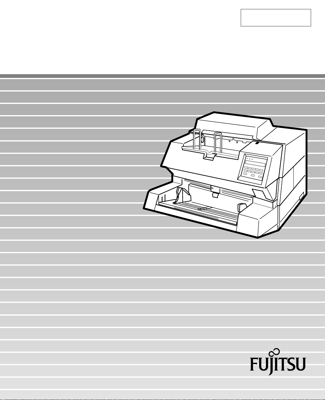
M3099EX/GX/EH/GH Image Scanner
Operator's Guide
Page 2
M3099EX/GX/EH/GH
Image Scanner
Operator's Guide
Page 3

M3099EX/GX/EH/GH Image Scanner Operator's Guide
Page 4

Edition
Date published
Revised contents
01 December,1995 First edition
02 April, 1996 M3099EX/GX added
03 May, 1996 Manual modified
Specification No. C150-E045-03EN
This equiepment has been tested and found to comply with the limits for a Class
A digital device,pursuant to Part 15 of the FCC Rules. These limits are designed
to provide reasonable protection against harmful interference when the equipment
is operated in a commercial environment. This equipment generates, uses, and
can radiate radio frequency energy and, if not installed and used in accordance
with the instruction manual, may cause harmful interference to radio communications. Operation of this equipment in a residential area is likely to cause harmful
interference in which case the user will be required to correct the interference at
his own expense.
This digital apparatus does not exceed the Class A limit for radio noise emissions
from digital apparatus set out in the Radio interference Regulations of the
Canadian Department of Communications.
Le pésent appareil numérique n’ément pas de bruits radioélectriques dépassant
les limites applicables aux appareils numériques de la classe A prescridtes dans
le Réglesment sur le brouillage radioélectrique dicté par le ministere des Communications du Canada.
MaschinenlärmInformationsverordnung 3. GSGV, 18-01. 1991: Der arbeisplatzbezogene Schalldruckpegel beträgt 70 dB (A) oder weniger gemäß ISO7779.
The contents of this manual may be revised without prior notice.
All Rights Reserved, Copyright © 1995, 1996 FUJITSU LIMITED.
Printed in Japan.
No part of this manual may be reproduced in any form without permission.
Page 5

Please send your comments on this manual or on Fujitsu products
to the following addresses:
FUJITSU COMPUTER PRODUCTS OF
AMERICA,INC.
2904 Orchard Parkway,San Jose.
California 95134-2022,U.S.A.
TEL:1-408-432-6333
FAX:1-408-432-3908
FUJITSU AUSTRALIA LIMITED
475 Victoria Avenue Chatswood.
N.S.W2067,AUSTRALIA
TEL:61-2-410-4555
FAX:61-2-411-8603
FUJITSU FRANCE S.A.
Bâtiment Aristote,17 rue Olof palme
94006 Créteil cedex,FRANCE
TEL:33-14-513-1616
FAX:33-14-399-0700
FUJITSU HONG KONG Limited
Room 2521,Sum Hung Kai Centre
30 Harbour Road Wanchal,Hong Kong
TEL:852-827-5780
FAX:852-827-4724
TLX:62667
FUJITSU CANADA,INC.
2800 Matheson Blvd.East,Mississauga.
Ontario 4X5,CANADA
TEL:1-905-602-5454
FAX:1-905-602-5457
FUJITSU DEUTSCHLAND GmbH.
Frankfurter Ring 211,
8000 München 40,F.R,GERMANY
TEL:49-89-32378-0
FAX:49-89-32378-100
FUJITSU ESPAÑA,S.A
Edificio torre Europa
Paseo de la Castellana 95 Madrid 28046,SPAIN
TEL:34-1-581-8400
FAX:34-1-581-8125
FUJITSU EUROPE LTD.
2,Longwalk Road,Stockey Park,Uxbridge
Middlesex,UB11 1AB,U.K
TEL:44-81-573-4444
FAX:44-81-573-2643
FUJITSU ITALIA S.p.A.
Via Melchiorre Gioia,No.8-20124
Milano,ITALY
TEL:39-2-6351
FAX:39-2-6572257
FUJITSU NORDIC AB
Kung Hans vag,S-19176
Sollentuna,SWEDEN
TEL:46-8-626-6000
FAX:46-8-626-6711
FUJITSU LIMITED
International Operations
Marunouchi 1-6-1, Chiyoda-ku,Tokyo 100
JAPAN
TEL:(81-3)3216-3211
FAX:(81-3)3213-7174
TLX:J2283
Cable:”FUJITSU LIMITED TOKYO”
Page 6

IMPORTANT NOTE TO USERS
READ CAREFULLY ALL OF THIS MANUAL BEFORE USING THIS PRODUCT.
IF NOT USED CORRECTLY, UNEXPECTED DAMAGES MAY BE CAUSED TO
THE USERS OR THE BYSTANDERS.
While all efforts have been made to ensure the accuracy of all information in this
manual, FUJITSU assumes no liability to any party for any damage caused by
errors or omissions or by statements of any kind in this manual, its updates or
supplements, whether such errors are omissions or statements resulting from
negligence, accidents, or any other cause. FUJITSU further assumes no liability
arising from the application or use of any product or system described herein; nor
any liability for incidental or consequential damages arising from the use of this
manual. FUJITSU disclaims all warranties regarding the information contained
herein, whether expressed, implied, or statutory.
FUJITSU reserves the right to make changes to any products herein, to improve
reliability, function, or design, without further notice and without obligation.
i
Page 7

Preface
This manual explains how to use the M3099EX/GX/EH/GH image scanner.
This manual contains COMPONENTS, INSTALLATION AND
CONNECTION, OPERATING INSTRUCTION,DOCUMENT SPECIFICATION, SPECFICATIONS, ENDORSER and SETUP MODE.
Refer to Reference Guide for the information about the routine operation of
the M3099EX/GX/EH/GH.
Reference Guide contains OPERATING INSTRUCTION, CLEANING,
REPLACEMENT OF PARTS, ADJUSTMENT and TROUBLESHOOTING.
The M3099EX/GX/EH/GH is very fast and highly functional image scanner
developed for volume filing, using charge-coupled device (CCD) image
sensors. This scanner features duplex scanning and high quality image,
processing with an automatic document feeder (ADF).
ii
Page 8
Conventions
Special information, such as warnings, cautions are indicated as follows:
WARNING
WARNING indicates that personal injury may result if you do not follow a
procedure correctly.
CAUTION
CAUTION indicates that damage to the scanner may result if you do not follow a
procedure correctly.
The following symbols are used in this manual.
Used for general WARNING and CAUTION.
Be careful not to pinch your fingers or hands.
iii
Page 9

iv
Page 10

CONTENTS
❑ CHAPTER 1 COMPONENTS
❑ CHAPTER 2 INSTALLATION AND CONNECTIONS
❑ CHAPTER 3 OPERATING INSTRUCTION
Checking the Components........................................................ 1-1
Units and Assemblies ............................................................... 1-2
Operator Panel(M3099EX/EH)..................................................1-4
Operator Panel(M3099GX/GH)............................................... 1-10
Buzzer Functions ....................................................................1-14
Precautions ............................................................................... 2-1
Inspection.................................................................................. 2-2
Cable Connection ..................................................................... 2-4
Turning the Power On ............................................................... 3-1
Button Specification and
Reading Mode Setting(M3099EX/EH) ......................................3-2
Button Specification(M3099GX/GH) .......................................3-17
❑ CHAPTER 4 DOCUMENT SPECIFICATION
Document Size.......................................................................... 4-1
Document Quality ..................................................................... 4-2
❑ CHAPTER 5 SPECIFICATIONS
Installation Specifications.......................................................... 5-1
Dimensions ............................................................................... 5-2
Consumables ............................................................................ 5-3
Option ....................................................................................... 5-4
❑ CHAPTER 6 ENDORSER
Specifications............................................................................ 6-1
Panel Operation ........................................................................ 6-2
❑ CHAPTER 7 SETUP MODE
Activating the Setup Mode ........................................................ 7-1
Contents of the Setup Mode .....................................................7-2
❑ GLOSSARY OF TEAMS ............................................................................... GL-1
❑ INDEX.............................................................................................................. IN-1
v
vvivii
Page 11

Page 12

CHAPTER
CHAPTER
INST ALLATION AND CONNECTIONS
2
CHAPTER
CHAPTER
4
OPERATING INSTRUCTION
3
DOCUMENT SPECIFICATION
1
COMPONENTS
COMPONENTS
INSTALLATION AND
CONNECTIONS
OPERATING
INSTRUCTION
DOCUMENT
SPECIFICATION
CHAPTER
CHAPTER
CHAPTER
GLOSSARY OF TEAMS
SPECIFICATIONS
5
ENDORSER
6
SETUP MODE
7
SPECIFICATIONS
ENDORSER
SETUP MODE
GLOSSARY
OF TEAMS
INDEX
INDEX
vii
Page 13

CHAPTER
1
COMPONENTS
After unpacking the scanner,confirm that all the components have
been received. This chapter describes the components of the
scanner, part names, and operator panel arrangement and their
function.
Checking the Components
Units and Assemblies
Operator Panel (M3099EX/EH)
Operator Panel (M3099GX/GH)
Buzzer Functions
Page 14
1
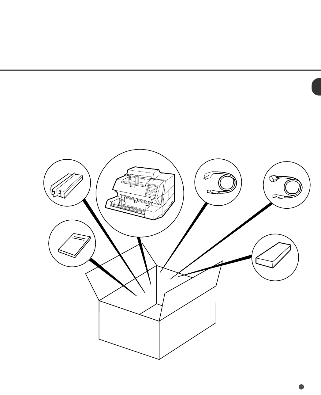
Cheking the Components
These high precision components must be handled with care.
Confirm that all the components shown in the following figure have been received.
If any component is missing, please contact your sales agent.
Terminator
(for M3099GX/GH)
Operator’s Guide
(this manual)
Scanner
Power cable
for North America
Power cable
for Europe
or
Consumable kit
1-1
Page 15
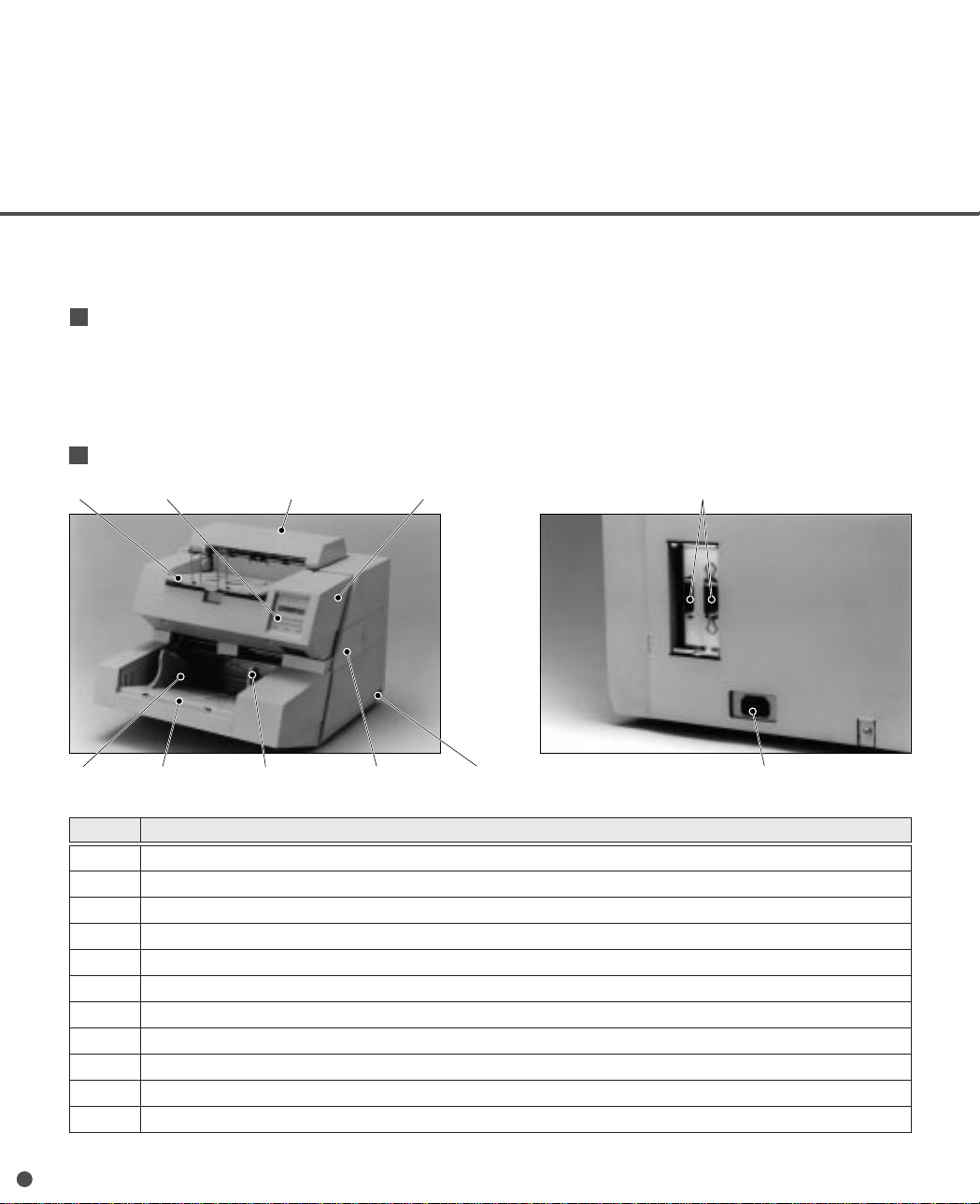
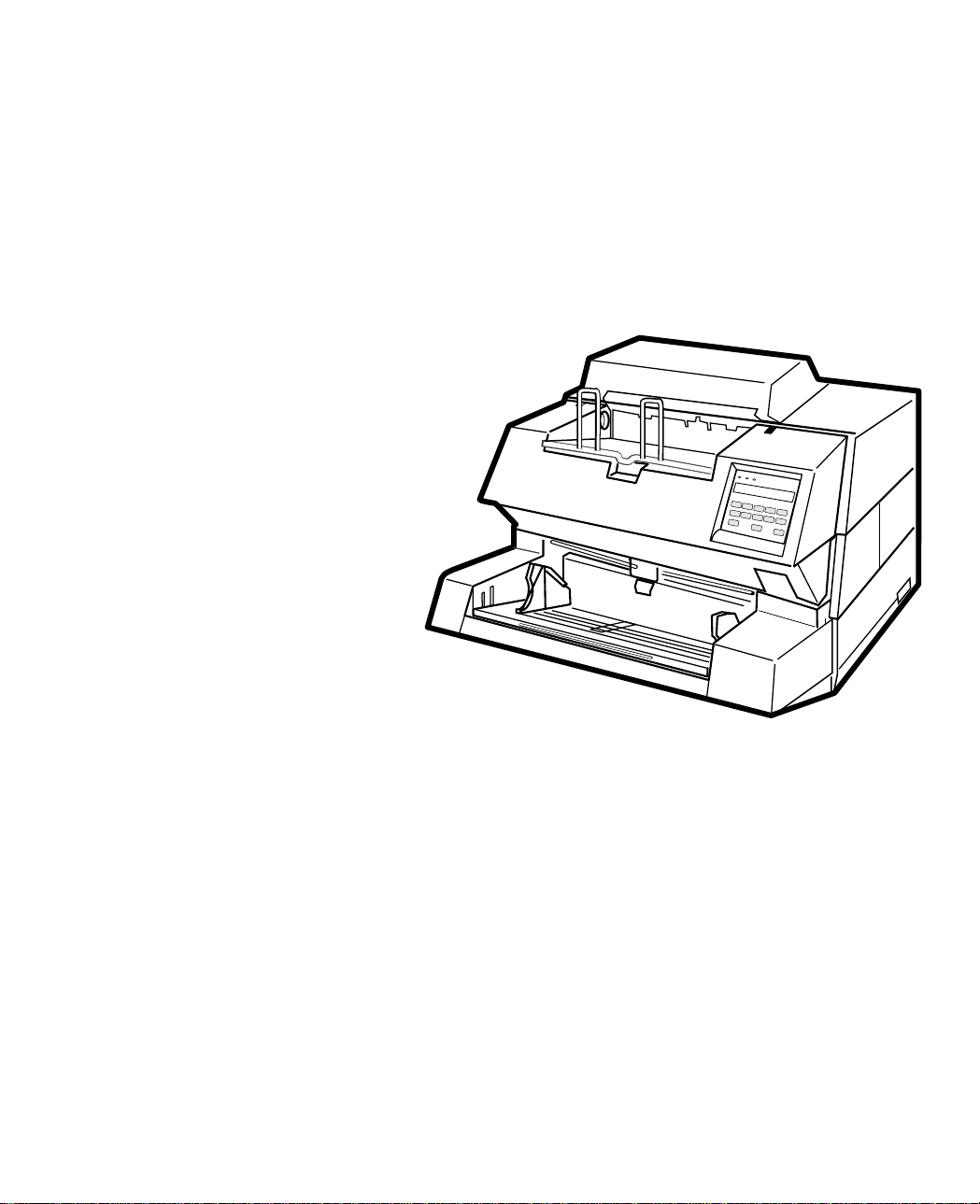
Units and Assemblies
This section shows the exterior view and assemblies of the scanner. This section also provides
names of each part and describes their functions.
Types
Both M3099EH and M3099GH have two types, 1000 sheets hopper type and 500 sheets hopper type. The
1000 sheets type has an extrusion endorser cover on the top of the unit and the 500 sheets type does not.
Therefore it is easy to tell one from another. Be aware that there may be a little difference in handling
between them.
Units
q Stacker e Operator panel t Endorser cover u Upper transport unit !0 Interface connectors
w Hopper r Extension y Paper guide i Side cover o Power switch !1 Power inlet
No. Function
q Stacker.
w Hopper.
e Used to operate the scanner.
r Used to prevent documents from hanging down.
t Open here when adjusting the print head position or when replacing the print head.
y Used to adjust the document size.
u Scans while feeding documents.
i Open here when replacing the back-side lamp.
o Turns on or off the power.
!0 Video and RS-232C (M3099EX/EH) or SCSI (M3099GX/GH) interface connectors.
!1 Connect the power cable from an AC power outlet here.
1-2
Page 16
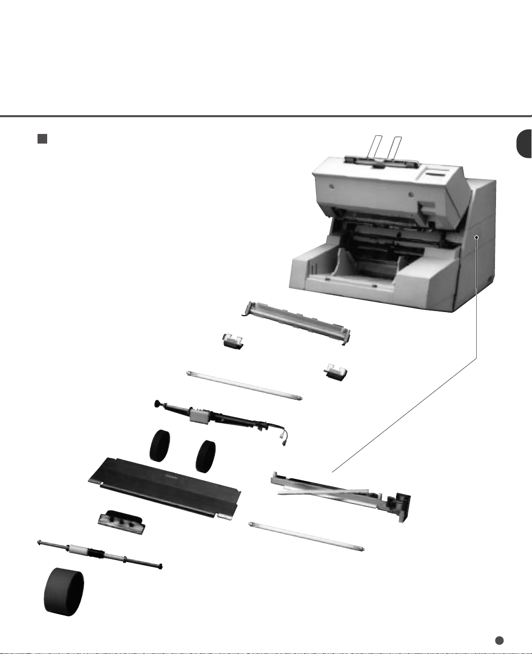
Assemblies
Lamp (Front-side lamp)
Roller ASY
Pick rollers
Sheet guide assembly
Lamp socket covers
Belt ASY
Belt
Guide plate
Pad
Lamp unit
Lamp (Back-side lamp)
1-3
Page 17
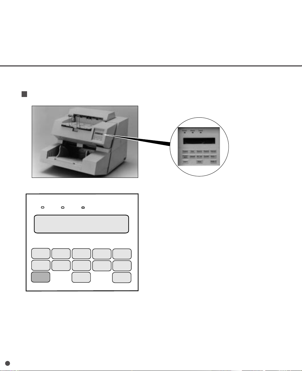
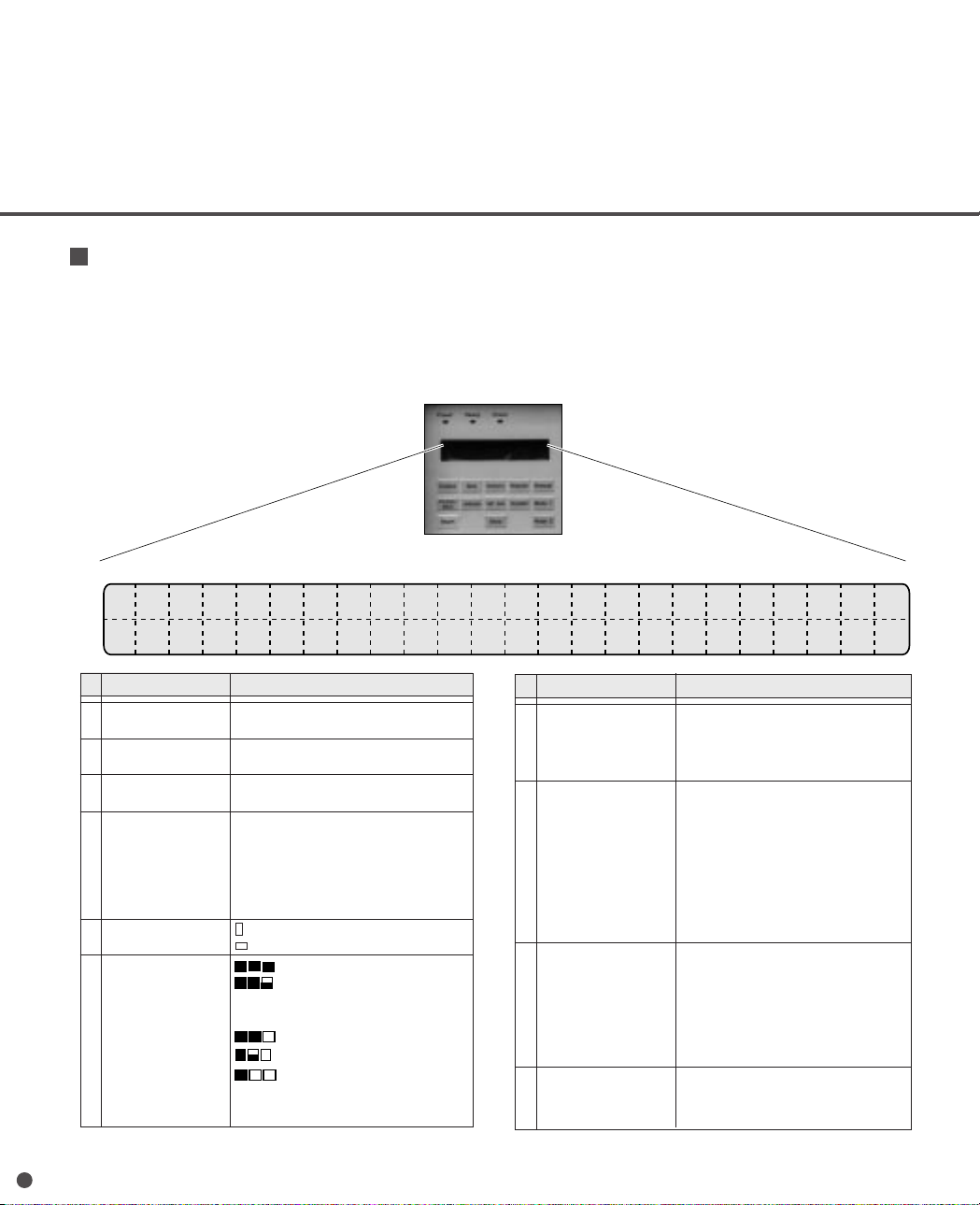
Operator Panel(M3099EX/EH)
The operator panel is located at the upper right hand side of the scanner. The panel consists of an
LCD (24 character x 2 line), LEDs and buttons.
Arrangement
Operator panel
1-4
Power
Ready
LCD
24 character x 2 line
Duplex
Front/
Back
Start
Size
Landscape Half tone
Check
Density
Stop
Resolution
Document Mode 1
Manual
Mode 2
Page 18
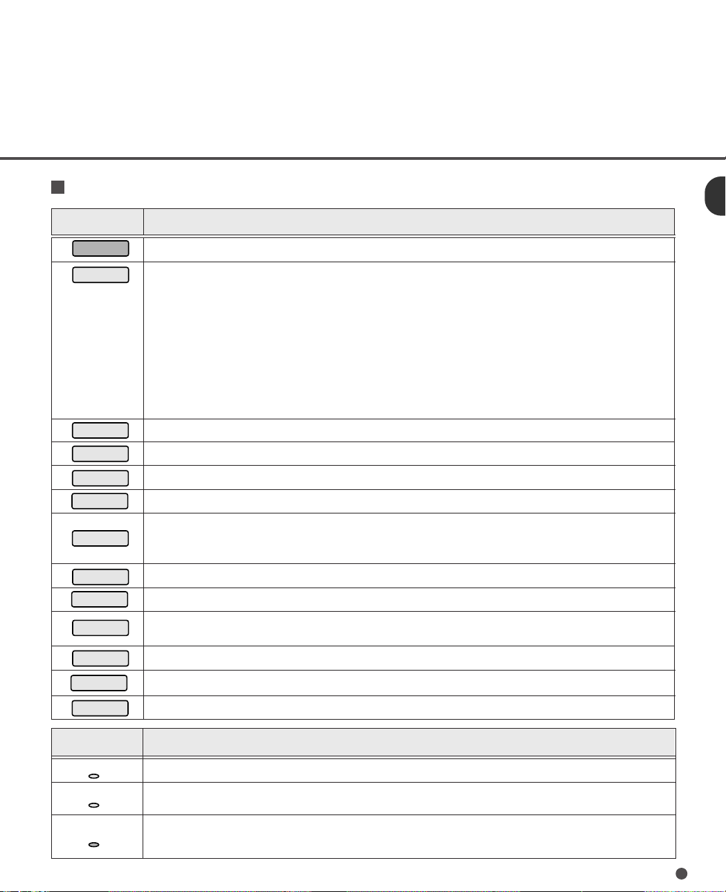
Button/LED Function
Resolution
Button name Function
Start
Stop
Duplex
Size
Density
Manual
Front/Back
Landscape
Half tone
When the Ready lamp is lit in the manual start mode, pressing this button starts a scanning operation.
When pressed during scanning:
The scanning operation immediately stops and the document under transport is ejected to the stacker.
A picked document, if any, is ejected to the stacker.
The hopper table is lowered to the bottom.
When pressed while waiting for Hopper-timer:
The hopper table is lowered to the bottom.
When pressed displaying the initial screen:
The abrasion counter is displayed.
When pressed occuring the temporary error:
The temporary error is recovered.
When pressed while setting the scanning mode:
The display returns to the initial screen.
Toggles the LCD screen between simplex and duplex reading mode.
Sets the document size.
Sets the scanning density.
Sets the scanning resolution.
Sets the manual mode.
Pressing this button lifts the hopper table to the level for manual mode. Pressing the button again releases the
mode and lowers the hopper table to the bottom.
Toggles the LCD screen between front-side and back-side reading mode.
Toggles the document scanning direction between the portrait and landscape mode.
Sets whether to execute halftone processing (dither or error diffusion) and also sets automatic separation
processing (dither or error diffusion if the image processing option is installed).
Document
Mode 1
Mode 2
Toggles the document scanning mode between the photo and linedrawing mode.
Activates the setup mode. (See Chapter7)
Activates the maintenance mode.
LED Function
Power
Ready
Check
Lights to indicate the power is on.
Lights when the image scanner becomes ready to read a document in the manual mode and manual start mode.
This indicator turns off when the Start button is pressed to read a document.
Lights when an equipment error occurs. An error messages is displayed on the LCD screen. This indicator blinks
when a document is jammed in the ADF. This indicator turns off when the jammed documents are removed from
the ADF and the upper transport unit is closed.
1-5
Page 19
LCD Display
The scanner is provided with simplex and duplex reading modes.
Simplex reading mode
The upper line (line 1) displays the current read mode for simplex reading.
The lower line (line 2) displays the mode set and messages when the buttons are pressed.
01
Upper
qwer ty u i
line
Lower
line
No.
Function Description
q Manual mode :ADF mode
w Reading mode D :Duplex reading
e Read side F :Front-side reading mode
r Size DL :Double-letter(only for
t Document :Portrait
orientation :Landscape
y Density :Very dark
2 3 4 5 6 7 8 9 10 11 12 13 14 15 16 17 18
No
. Function Description
M :Manual mode
S :Simplex (front-side) reading
B :Back-side reading mode
M3099EX)
LT :Letter
LG :Legal
A3 :A3(only for M3099EX)
A4 :A4
:Dark
AT1 :Dynamic threshold AT1*
AT2 :Dynamic threshold AT2*
:Normal
:Light
:Very light
*Only when the image processing
option is available.
u Resolution 400 :400dpi
i Halftone processing :No halftone processing
separation(error diffusion)*
o Photo/linedrawing P. :Photo mode
mode L. :Linedrawing mode*
!0 Image processing
option
19
20 21
22
23
o!0
300 :300dpi
240 :240dpi
200 :200dpi
HT1:Dithering
HT2:Error diffusion
LP1:Automatic separation(dither)*
LP2:Automatic
When the image processing option
is not installed, automatic
separation is not available.
*When linedrawing mode is
selected,check that the 3 mm
margin of the read area is
specified as a drop-out color.
:No
> :Yes
1-6
Page 20
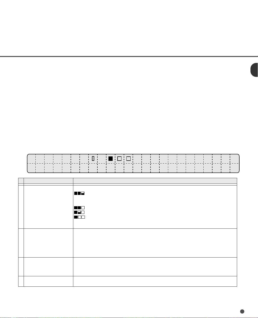
Duplex reading mode
The upper line (line 1) displays the current read mode for front-side reading.
The displayed messages are the same as those in the simplex reading mode.
The lower line (line 2) displays the current read mode for back-side reading.
Only the density, halftone processing, photo/linedrawing mode and image processing option can be
specified independently.
The other mode is the same as that for front-side reading.
01
Upper
M
line
Lower
line
No.
Function Description
q Density ■■■:Very dark
w Halftone processing :No halftone processing
e Photo/linedrawing mode P. :Photo mode
r Image processing option :No
2 3 4 5 6 7 8 9 10 11 12 13 14 15 16 17 18 19 20 21 22 23
A
DF
D
B
:Very light
4
q
:Dark
AT1 :Dynamic threshold AT1*
AT2 :Dynamic threshold AT2*
:Normal
:Light
*Only when the image processing
option is available.
HT1:Dithering
HT2:Error diffusion
AT1:Automatic separation (dither)*
AT2:Automatic separation (errordiffusion)*
*Only when the image processing option is available.
L. :Linedrawing mode*
*When linedrawing mode is selected, check that the 3 mm margin
of the read area is specified as if a drop-out color.
> :Yes
400 L.
w
er
>
1-7
Page 21

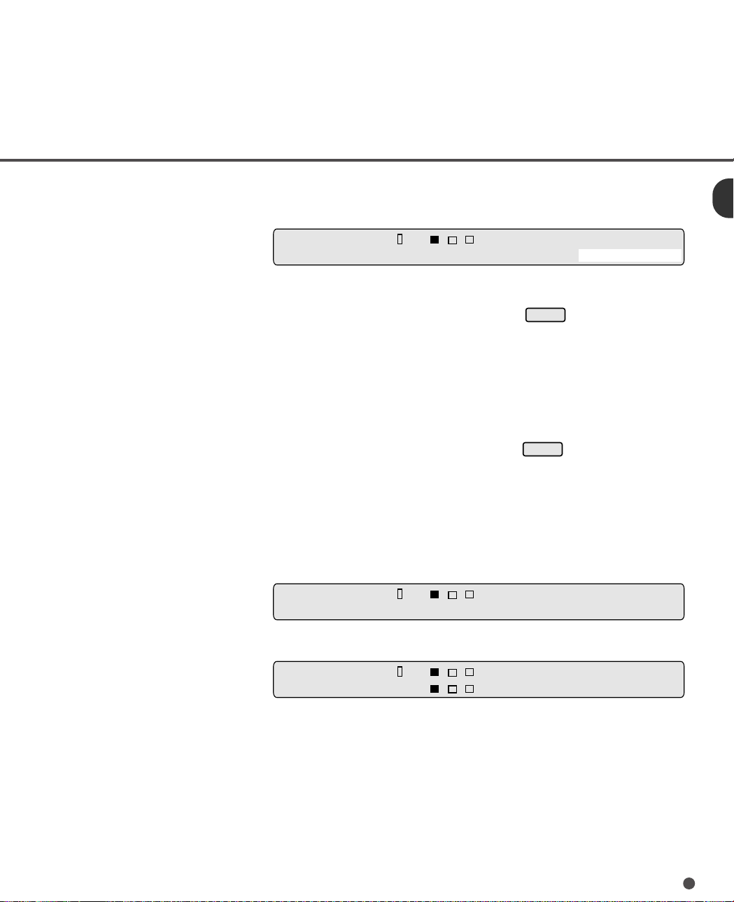
Operation status
Operation status is indicated by the following message:
<Power-on>
<Warning>
<Reading counter>
When the lamps are ready to read, the screen changes to the initial
screen of the simplex or duplex reading mode.
Warmi ng
XX
XX
X
INK EMPTY
_
XXX
up Now! !
XXX
The upper line displays the current read mode for front-side reading.
The lower line is blinking and displays the ink empty of print head after
the scanning operation.
This warning display will be reset, when the covers are opened, or
Stop
is pressed, or Start command is issued. The operator must
change the print head and reset the life counter. (See Chapter 6
ENDORSER.)
Example of simplex reading:
SF A4 400
L. >
XX
Reading
counter
X
1-8
The reading counter is displayed after a read operation starts.
The reading counter disappears when:
• The next scanning starts.
• The valid switches are pressed.
• The error is cleared.
Page 22
Stop
Stop
<Abrasion counter>
SF A4 400 L. >
X
XXXXX
Abrasion
counter
<IPC-2 pre-set mode>
The abrasion counter is displayed when
is pressed in the
initial screen.
The abrasion counter disappears when:
• The next scanning starts.
• The valid switches are pressed.
• The error is cleared.
The abrasion counter is not displayed if
is pressed during
blinking.
The abrasion counter displays the accumulative number of read
document.
This counter can be reset to zero by following the procedure
shown in Chapter 7 (page 7-7).
Simplex reading mode
S✳FA4 400 L. >
Duplex reading mode
D✳FA4 400 L. >
DB
L. >
When IPC-2 pre-set mode is set, an asterisk ( ✳ ) is displayed.
The method of IPC-2 pre-set mode is shown in setup mode.
1-9
Page 23
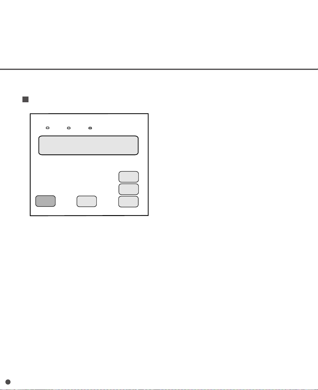
Operator Panel(M3099GX/GH)
The operator panel is located at the upper right hand side of the scanner. The panel consists of an
LCD (24 character x 2 line), LEDs and buttons.
Operator panel
Power
Read
Check
LCD
24 character x 2 line
Start
Stop
Manual
Mode 1
Mode 2
1-10
Page 24
Button/LED Function
Button name Function
Start
Stop
Manual
Mode 1
Mode 2
This button is used to indicate
button is disabled while scanner operates in On-line.
This button is used to indicate
button is used to cancel temporary error while operating at On-line.
This button is used to select manual feeding mode. By pressing this button, setting is switched between
manual feeding and ADF mode.
Activates the setup mode. (See Chapter 7)
Activates the maintenance mode.
LED Function
Power
Ready
Check
When the Power switch is turned on, this LED is turned on.
While scanning,this LED is turned on.
When a scanner malfunction is detected, this LED is turned on. When temporary error (Paper Jam, and so
on) is detected, this LED is blinked. When temporary error is cleared and
will be turned off.
Start
to scanner in maintenance mode or SETUP mode at Off-line. This
Stop
to scanner in maintenance mode or SETUP mode at Off-Line. This
Stop
button is pressd, this LED
1-11
Page 25

LCD Display
When the Power switch is turned on, the following messages appear on LCD at On-line.
<Power-On to Ready>
Warmi ng
<Operation Ready>
S✳ canne r Read y
_
up Now!!
<Operation Ready in Manual
Feed mode>
<Warning>
<Reading counter and
Abrasion counter>
Manual Feed
Scann e r Read y
INK EMPTY
The lower line is blinking and displays the ink empty of print head after
the scanning operation.
This warning display will be reset, when the covers are opened, or
Stop
is pressd, or Start command is issued. The operator must
change the print head and reset the ink counter.
cann ad
S
er Re
y
XXX
Reading
counter
The reading counter is displayed after a read operation starts.
1-12
Page 26

Stop
cann ad
S
er Re
X
XX
Abrasion
counter
XXX
<IPC-2 pre-set mode>
The abrasion counter is displayed when
is pressed in the
Ready screen.
The abrasion counter displays the accumulative number of read
document.
This counter can be reset to zero by following the procedure shown
in Chapter 7 (page 7-7).
The reading counter or abrasion counter disappears when:
• The next start commnad is issued.
• The valid switches are pressed.
• The error is cleared.
S✳ canne r Ready
When IPC-2 pre-set mode is set, an asterisk ( ✳ ) is displayed.
The method of IPC-2 pre-set mode is shown in setup mode.
1-13
Page 27

Buzzer Functions
The scanner has a buzzer to indicate that an error has occurred.
Error Function
Equipment error Sounds for 3 seconds. The buzzer turns off when any button is pressed or
the power is turned off. Even when a button is pressed, the scanner
continues to display the error.
Temporary error Sounds during 3 seconds with 0.5 second interval.
The buzzer turns off when any button is pressed or power is turned off.
Even when a button is pressed, the scanner continues to display the error.
The buzzer function can be set on or off by following the procedure in Chapter7 SETUP MODE.
1-14
Page 28

CHAPTER
2
INSTALLATION AND CONNECTIONS
The chapter describes how to install and connect the scanner.
Precautions
Inspection
Cable Connection
Page 29

WARNING
Place the machine with no portion of the scanner hangs over the desktop.
Never attempt to move or relocate the machine without help. And hold the
horizontal plane of the scanner bottom. (Not inclined plane)
ACHTUNG
Precautions
This section describes precautions when installing the scanner.
Do not install the scanner in the following places and environments.
• Place the scanner away from electrical noise sources, strong magnetic fields and air flow. If the scanner
is used near an air conditioner, copying machine, or TV set, the scanner may operate incorrectly.
• Keep the scanner out of the sun and away from heaters. These environments may shorten the scanner
life or cause hardware failures.
• Do not install the scanner in a place where vibrations may occur. This environment may cause hardware
failures or may cause the scanner to operate incorrectly.
• Do not install the scanner in a humid, dusty, or damp places. These environments may shorten the
scanner life or cause hardware failures. Do not place the scanner where liquid spills may occur.
Stellen Sie den Scanner sicher auf eine waagerechte, ebene Flache.
Bewegen Sie den Scanner nicht ohne Hilfe.
• Be aware of the static electricity. Be sure that the flooring and the desk are made of materials that do
not generate the static electricity.
See Chapter 5 SPECIFICATIONS for the informantion such as the size of the installation space.
2-1
Page 30

Inspection
This section describes how to check the labels.
Make sure that the input voltage indicated on the temporary label agree with your power source.
Label C
Temporary label
After checking the power voltage rating of the scanner with the temporary label, connect the correct
power supply to the scanner.
Label A (An example)
Label A
Label D
Label B
2-2
Page 31

Label B (An example)
MODEL M3099EH IMAGE SCANNER
PART NO. CA02869-B202 AC100-120/200-240V
SER. NO. 1 phase 50/60Hz
DATE 1993-11 2.5/1.25A 65 kgf
FUJITSU LIMITED
Label C (An example)
MODEL NAME HLS-001E
PART NO. CA02869-B001
MODEL - 0 1 2 3 4 5 6 7 8 9
REV. - 0 1 2 3 4 5 6 7 8 9
- 0 1 2 3 4 5 6 7 8 9
Label D (An example)
Temporary Label (An example)
This machine is wired for AC100-120V.
To change the Voltage setting, call the service personel.
CAUTION
If the power voltage rating of the scanner is different from your power
source, please contact manufacturer’s authorized service center.
MADE IN JAPAN
2-3
Page 32

Cable Connection
This section describes how to connect the cables.
Connect the cables as follows:
Turning the power switch off
Press “O” side of the power switch to turn the power off.
Power OFF
Power switch
Connecting the power cable
Connect the power cable to the power inlet of the device and a power outlet.
Power inlet
for North America
Power cable
Power ON
Power outlet
for Europe
2-4
Page 33

Connecting the interface cable
(M3099EX/EH)
Connect the video interface and RS-232C interface cables and secure them with hooks and screws.
Connect the other ends to the host machine.
[ Back side of the scanner ]
Interface cable for RS-232C
Screws
Catches
Interface cable
for RS-232C
Interface cable
for video
To the host machine
Interface connector
for video
(M3099GX/GH)
Connect the SCSI interface cables and secure them with hooks and connect the other ends to the host
machine. When the scanner is at the terminal side, connect the terminator to the connector to which an
interface cable is not connected.
Interface cable
for SCSI
To the host machine
NOTE
SCSI-ID is set to No. 5. Refer to Chapter 7 when changing the setting.
[ Back side of the scanner ]
Catches
Interface connector for SCSI
2-5
Page 34

2-6
Page 35

CHAPTER
3
OPERA TING INSTRUCTION
This chapter describes how to turn the power on, and also describes button specification and reading mode setting.
Refer to Reference Guide about information on loading document
and opening/closing the upper transport unit.
Turning the Power On
Button Specification and Reading Mode Setting
(M3099EX/EH)
/
Button Specification (M3099GX
GH)
Page 36

3
Turning the Power On
This section describes how to turn the power on.
Press “I” side of the power switch. The power goes on and the green Power lamp at the operator
panel lights.
Operator panel
Power OFF
Power switch
Power ON
3-1
Page 37

Button Specification and Reading Mode Setting
Duplex
(M3099EX/EH)
This section describes the button specifications and setup details for each of the simplex (front-side),
duplex (front-side) and duplex (back-side) reading modes.
When reading mode is set by the command from the host computer, the following button operation is
not required.
This button is used to select simplex or
duplex document reading mode. Press this
button to toggle the display between the
initial screens of the simplex and duplex
reading modes.
Front/
Back
This button is valid only in the duplex
reading mode. Press this button to toggle
the read side between front and back.
“F” and “B” blink alternately for the setting of
front or back-side.
button
button
<Initial screen of the simplex reading mode>
F
A
A
A
4
4
4
4
4
S
D
F
D
B
<Initial screen of the duplex reading mode>
<Initial screen of the duplex reading mode>
F
D
D
B
<Screen 1>
(Blinking)
F
D
00 L.>
4
Duplex
button pressed
00 L.>A
4
00 L
4
Front/
button pressed
Back
00 L
4
L.>A
.
L
.>>
.
3-2
D
B
<Screen 2>
F
D
D
B
(Blinking)
A
L
.>>
Front/
Back
4
button pressed
00 L
4
.
L
.>>
Page 38

Simplex (front-side) reading mode setting
<Initial screen of the simplex reading mode>
Size
Selects a document size. When this
button is pressed the lower line is displayed as shown in Screen 3.
(M3099EX)
Each time this button is pressed, “DLT”,
“LT”, “LG”, “A3” or “A4” starts blinking in
turn and the size displayed on the upper
line changes accordingly. If the direction
indicated on the upper line is “ ”, only
“LT” or “A4” can be selected.
(M3099EH)
Each time this button is pressed, “LT”,
“LG”, or “A4” starts blinking in turn and the
size displayed on the upper line changes
accordingly.
button
F
A
A
A
4
4
4
S
<Screen 3>
S
F
S
ize: LD
S
F
S
ize:LTLG
00 L.>
4
00 L.>
4
T
LT
LG A3 A4
(Blinking)
00 L.>
4
A4
(Blinking)
3-3
Page 39

Resolution
Density
Selects a density for the read operation.
When this button is pressed, the lower line is
displayed as shown in Screen 4. Each time
this button is pressed, the blinking part in the
lower line changes, and the density indicated
on the upper line changes according to the
blinking part.
The lower line is displayed as shown below.
button
Lower line display
Without image
processing option
Blinking
order
<Screen 4>
S
FA
en :
D
With image
processing option
Auto 1
Auto 2
4
. (
(Blinking)
Very dark
Dark
Dynamic threshold
Simplified dynamic threshold
Normal
Light
Very light
00 L.>
4
A
T
Description
A
u
to)2
3-4
Selects a resolution for the read operation.
When this button is pressed, the lower line
is displayed as shown in Screen 5. Each
time this button is pressed, “400”, “300”,
“240” or “200” starts blinking in turn and the
resolution indicated on the upper line
changes accordingly.
button
<Screen 5>
S
FA
R
es . :
4
0
(Blinking)
00 L.>
4
3
0
2
4
0
0
24
000
Page 40

Landscape
Specifies landscape or portrait mode for
reading. When this button is pressed, the
lower line is displayed as shown in Screen 6.
Each time this button is pressed, the blinking
part changes in turn and the mode indicated
on the upper line changes accordingly.
NOTE
Landscape mode can be selected only when the
document size is LT or A4.
button (*1)
_5.5
(Portrait)
*1; This button is available only for M3099EX.
(Landscape)
(M3099EX)
(M3099EH)
<Screen 6>
S
FA
S
ize: L
S
FA
S
ize: LTLG
4
D
T
L
4
00 L.>
4
T
LG
4
A
A
3
4
(Blinking)
00 L.>
A
4
(Blinking)
3-5
Page 41

Half tone
button
<Screen 7>
Specifies the halftone processing (dither
or error diffusion). When this button is
pressed, the lower line is displayed as
shown in Screen 7. Each time this
button is pressed, the blinking part
changes in turn, and the halftone indicated on the upper line changes accordingly.
Without
option
With
option
D
FA
H
alft n
Blinking
order
1
2
3
4 OFF
5 OFF HT2
①
OFF
blinking
OFF
OFF
4
e
o
:
O
Dispiay
②③
HT1 LP1
HT1
blinking
HT2
blinking
HT1
F
F
LP1
LP2
LP1
blinking
LP2
blinking
4
00 L.>
T
H1
②③①
(Blinking)
1
H
T
P
L
Not displayed unless
the image processing
option is installed.
Explanation
Line Art (Halftone
processing off)
Halftone processing (dither) *1
Halftone processing (error diffu-
sion)
Automatic separation (dither) *2
Automatic separa-
tion (error diffu-
sion) *2
3-6
*1: Select one of these settings to read data such as photo-
graphs, illustration, or colored maps.
*2: If photographs and characters are mixed in a document, the
characters are read clearly and the photographs are read in
halftone. This setting is only available when the image
processing option is installed.
Page 42

Document
Selects the type of document. When this
button is pressed, the lower line is displayed
as shown in Screen 8. Each time this
button is pressed, “LINE” or “PHOTO” starts
blinking in turn and the document selection
indication displayed on the upper line
changes accordingly.
button
<Screen 8>
S
FA
.:
DOC
00
4
(
Ln
.
L
4
ie)P.(Ph
HT
(Blinking)
P1
.
oto
>
)
Display
P. (Photo)
L. (Line)
*1; Top 3mm part of the read area should be left
blank (grounding color ) by specifying a drop-out
color.
Explanation
For light adjustment or when there is a
dark background color on the document.
Select this setting to read line drawing.
*1
3-7
Page 43
Manual
This button is used to set or release the
manual mode.
button
<Screen 9>
S
M
FA
4
4
00
T1 L.>
H
Pressing this button displays <Screen 9>.
The manual mode is set and the hopper
goes up. Pressing this button again releases the manual mode and lowers the
hopper to the bottom position.
(Manual mode set)
Manual
<Initial screen of the simplex reading mode>
S
FA
4
4
button pressed
00
HT 1
(Manual mode released)
>
.
L
3-8
Page 44

Screen transition
<Initial screen of the simplex reading mode>
HT1
A
S
4
F
00 L
4
>
.
Size
Density
Resolution
Landscape
Halftone
Document
S
FA
4
S
ize: LTLG
S
FA
4
e
n.
D
S
FA
4
R
es
.
S
FA
4
z
S
e
i
:
S
FA
4
alfton
H
S
FA
4
L
.
D
O
C
:
:
4
03
0
:
LT LGA
e
O
F
F
:
e
i
L
HT1
00 L.>
4
4
A
HT1
00 L.>
4
AT(
00 L.>
4
00 2
00 L.>
4
4
00 L
4
T
H1
00
4
P.( )
.
o)2
t
u
A
HT1
2
40 00
HT1
HT1
P
L
HT1
on
(
h
P
>
.
L
.
>
)
o
t
SM
FA
Manual
To the initial screen of the simplex reading mode (*1)
*1: Pressing the
display to the initial screen of the simplex reading mode.
4
Stop
Stop
button during reading mode returns the
HT1
00 L
4
>
.
3-9
Page 45

Duplex (front-side) reading mode setting
Resolution
<Initial screen of the duplex reading mode>
F
D
D
B
Use the following buttons to set the scanner when it reads the front-side of a document in duplex mode.
This description applies to the case when reading the back-side except Density, Halftone and Document
buttons.
Size
This button is used to select a document size.
For details, see the explanation of <Screen 3>.
(M3099EH)
(M3099EX)
button
<Screen 10>
D
FA
S
ize:L
D
FA
S
ize: L
4
A
4
T
LG
4
T
DA
T
L
00 L
4
00 L.>
4
A
4
(Blinking)
00 L.>
4
A
LG
3
L
4
(Blinking)
.
.>>
This button is used to select a scanning
density.
For details, see the explanation of <Screen 4>.
3-10
Density
This button is used to select a scanning
resolution.
For details, see the explanation of <Screen 5>.
button
button
<Screen 11>
D
FA
en :
D
<Screen 12>
D
FA
Re
4
4
. (
(Blinking)
4
:
s
4
.0
(Blinking)
4
0
0
3
00 L.>
A
T
A
u
to)2
00 L.>
2
0
40 200
Page 46

Half tone
Landscape
button
This button is used to select document reading
direction in portrait or landscape mode.
For details, see the explanation of <Screen 6>.
NOTE
The landscape mode can be selected only
when the document size is LT or A4.
(M3099EH)
(M3099EX)
<Screen 13>
D
FA
S
ize:
D
FA
S
ize: L
(Portrait)
4
T
4
T
D
L
GA
L
T
(Landscape)
00 L.>
4
4L
00 L.>
4
GA
L
3
A
4
(Blinking)
(Blinking)
This button is used to select whether or not to
perform halftone (dither or diffusion) processing.
For details, see the explanation of <Screen 7>.
button
<Screen 14>
D
FA
H
alft n
H
1
T
P
L
3-11
4
e
o
:
O
F
00 L.>
4
T
H1
F
②①③
(Blinking)
Not displayed unless the image
processing option is installed.
Page 47

Document
This button is used to select linedrawing mode
or photo mode.
For details, see the explanation of <Screen 8>.
button
<Screen 15>
D
FA
DOC . :
4
L
(
.
00 P.>
4
Ln
ie)P.(Ph
(Blinking)
oto
)
Manual
This button is used to set or release the
manual mode.
For details, see the explanation of <Screen 9>.
button
<Screen 16>
D
M
FA
4
4
00
H
T
DB
(Manual mode set)
Manual
<Initial screen of the duplex reading mode>
D
FA
4
button pressed
00
4
(Manual mode released)
H
T1
1
>
.
L
>
.
L
>
L
.
>DB
L
.
3-12
Page 48

Screen transition
<Initial screen of the duplex reading mode>
D
A
F
4
D
B
Front/
(Blinking)
A
4
D
F
D
B
Back
HT1
00 L
4
button pressed
HT1
00 L
4
>
.
>
.
>
.
L
Size
D
FA
4
S
ize: LTLG
00 L.>
4
HT1
4
A
Density
Resolution
Landscape
Half tone
Document
Manual
D
FA
e
D
D
FA
R
es
D
FA
z
S
e
i
D
FA
alfton
H
D
FA
.
O
C
:
D
FA
D
B
4
n.
:
4
4
.
:
4
LT LGA
:
4
e
4
L
4
03
0
O
:
iD
L
00 L.>
4
AT(
00 L.>
4
00 2
00 L.>
4
4
00 L
4
F
F
T
H1
00
4
P.( )
e
00 L
4
Stop
HT1
t
u
A
HT1
40 00
HT1
HT1
P
L
HT1
(
.
h
P
HT1
o)2
2
L
on
t
L
>
.
>
.
)
o
>
.
>
.
To the initial screen of the duplex reading mode (*1)
*1: Pressing the
Stop
button during reading mode returns the display to
the initial screen of the duplex reading mode.
3-13
Page 49

Duplex (back-side) reading mode setting
Document
Half tone
Density, Halftone and Document buttons are
available when reading the back-side.
<Initial screen of the duplex reading mode>
F
D
A
4
00 L
4
.
Density
This button is used to select a reading
density. For details, see the explanation of
<Screen 4>.
This button is used to select whether or not
to perform the halftone (dither or error
diffusion) processing. For details, see the
explanation of <Screen 7>.
button
button
D
B
<Screen 17>
en :
D
D
B
<Screen 18>
H
alft n
D
B
L
.>>
(Blinking)
A
.
T
(
to)2
u
A
L.>
Not displayed unless the image
processing option is installed.
(Blinking)
③➁➀
e
o
:
O
F
F
T
H1
H
P
L
1
T
L.>
3-14
This button is used to select line drawing
mode or photo mode. For details, see the
explanation of <Screen 8>.
button
<Screen 19>
DOC . :
D
B
(Blinking)
(
Ln
.
L
ie)P.(Ph
00 P.>
4
oto
)
Page 50

Screen transition
<Initial screen of the duplex reading mode>
F
D
A
4
D
B
4
HT1>.
00 L
Front/
button pressed
Back
>
.
L
D
F
B
D
D
F
B
D
(Blinking)
A
4
A
4
HT1
00 L
4
Front/
button pressed
Back
HT1
00 L
4
>
.
>
.
L
>
.
>
.
L
*1: Pressing the
Density
Half tone
Document
the initial screen of the duplex reading mode.
D
D
B
alfton
H
D
B
D
.
O
C
D
B
To the initial screen of the duplex
reading mode (*1)
Stop
button during reading mode returns the display to
e
n.
:
e
O
:
L
:
L
Stop
AT(
F
F
T
H1
P.( )
e
i
.
o)2
t
u
A
L.>
P
L
L.>
on
(
h
P
o
t
L.>
)
3-15
Page 51

Stop
Stop
Start
Press each button to start or stop reading.
/
Stop
button
Start
Read operation can be started in either manual or automatic start mode. To start reading in manual
start mode, press this button while the ready indicator is lit. (*1)
*1: Make sure that the LCD is the initial screen of simplex or duplex reading mode. If not, press
Manual start mode: Reading is started by
Automatic start mode: Reading is started by a command from the host machine.
Stop
This button is effective regardless of mode: manual or automatic mode.
Press this button to stop read operation.
When
During reading: Reading immediately stops and the document being fed is ejected to the stacker. The
Before reading: A picked document, if any, is ejected to the stacker. The button works only when a
NOTE
If a document which is not picked remains in front of ADF, set the document on the hopper again.
button
button once, then press
Start
button.
Start
button.
button
button is pressed:
hopper table is lowered to the bottom.
document is picked. The hopper table is lowered to the bottom.
3-16
Page 52

Button Specification(M3099GX/GH)
Start
Stop
Mode 1
Mode 2
This section describes the button specifications.
Manual
This button is used to select manual feed mode. Pressing this button switches the setting between Manual
mode and ADF mode.
When this button is pressed, the scanner enters manual feed mode and the hopper goes up. If the button
is pressed again, the scanner exits manual feed mode and the hopper goes down.
button
Stop
/
button
These buttons are usedd in Off-line mode. When
starts document feeding. When
feeding.
button is also used in On-line mode to cancel the temporary error condition.
This button is used to transit to SETUP mode when the power is on. When
power is turned on, the scanner enters SETUP mode.
This button is used to transit to maintenance mode when the power is on. When
and power switch is turned on, the scanner enters maintenance mode. Maintenance mode is used for
maintenance/diagnostic purpose. See M3099EX/GX/EH/GH IMAGE SCANNER CE MANUAL.
button
button
Stop
button is pressed in Off-line mode, the scanner stops document
Start
button is pressed in Off-line mode, the scanner
button is pressed and
Mode 1
Mode 2
button is pressed
3-17
Page 53

3-18
Page 54

CHAPTER
4
DOCUMENT SPECIFICATION
This capter describes the document size and document guality of
the scanner.
Document Size
Document Quality
Page 55

Document Size
The following figure shows document sizes that the scanner can read.
A
Feeding Drection
Feeding direction
B
Scanner
M3099EX/GX
M3099EH/GH*
A
297 (11.7 in)
216 (8.5 in) 356 (14 in)
B
432 (17 in)
MinimumMaximum
A
76 (3 in)
76 (3 in)
B
63 (2.5 in)
63 (2.5 in)
(Unit : mm)
*The size that M3099EH/GH can read is shown in the table above. However, a
document of up to A3 size can be fed.
4-1
Page 56

Document Quality
This section describes document types and weights available for the scanner, and precautions.
Document type
The recommended paper type for document is as follows:
NOTE
Use the specified paper only. (In rare occasion, double feeding may occur or document damage may
occur.)
• Fine paper
• Plain paper (for example, the paper specified for XEROX4024)
• OCR paper
When using all other type paper, check that it is successfully fed by ADF before performing a reading
operation.
Paper weight
The paper weight is as follows :
• 52 to 127 g/m2 3.9 to 34 lb)
Precautions
Be careful not to scan the following document. Preliminary document feed test may be necessary to avoid
the unexpected errors. If the document slips in ADF (JAM error) or double feed occurs frequently,
separation pressure adjustment in Reference Guide may be effective.
• Paper with clips
• Paper with wet ink
• Paper of which thickness is not constantly equal. (like envelope)
• Paper with large rumples or curl. (See NOTE on the next page.)
• Paper with folds or tears
• Tracing paper
• Coating paper
• Carbon paper
• Carbonless paper
• Paper smaller than 76 mm x 63 mm size, or larger than A3
• Other than paper ; clothes, metal foil, or OHP film
• Photographic paper
• Paper with notches on its side
• Other than rectangle paper
4-2
Page 57

CAUTION
Do not feed an important original document to prevent damage to it in rare
case.
When scanning a translucent document, set the density to light mode.
To prevent roller smudging, avoid scanning a document filled out in pencil. Clean the roller as often as
possible when scanning many document. Once every 1000 sheets is recommended.
The chemical composition of some carbonless papers may react with the roller rubber and damage the
rubber. Check the carbonless papers before use.
The carbonless papers may be used if:
• Paper weight is 52 g/m2 (13.9 lb) or more.
• Hopper load is 500 sheets or fewer.
NOTE
• If carbonless papers are used, clean the roller twice as often as usual.
• Paper should be straightened to fit the condition below.
More than
30 mm
Less than
Feed direction
3 mm
Read surface
Top of the paper
More than
30 mm
Feed direction
Less than
5 mm
Read surface
• Some papers might have a curl on the stack when you use curled paper having some fold wrinkle.
4-3
Page 58

4-4
Page 59

CHAPTER
5
SPECIFICATIONS
This chapter describes the installation specifications, dimensions, consumables, option.
Installation Specifications
Dimensions
Consumables
Option
Page 60

Installation Specifications
The following table lists the installation specifications of the scanner.
Item
Dimensions
(mm)
Weight (kg)
Input power
Power consumption 250 VA or less
Ambient
condition
Heat capacity 110 kcal/H (440 BTU/H)
500 sheet hopper type
1000 sheet hopper type
Voltage 100 to 120 VAC, 220 to 240 VAC ±10 %
Phases
Frequency 50/60 + 2% -4% Hz
Device status Operating Not operating
Temperature 5 to 35°C -20 to 60°C
Humidity 20 to 80 % 8 to 95 %
610 (24 in)
55 (121 lb.) for 500 sheet hopper type
65 (143 lb.) for 1000 sheet hopper type
Single-phase
(41 to 95°F) (-4 to 140°F)
Specification
680 (26.8 in)
HeightDepthWidth
470 (18.5 in)
530 (20.9 in)680 (26.8 in)610 (24 in)
5-1
Page 61

Dimensions
610
5-2
680
(1000 sheet hopper type)
(500 sheet hopper type)
530
470
(unit: mm)
Page 62

Consumables
The following table lists consumables used for the scanner. Be sure to keep some consumables in stock.
Customer is responsible to change these items periodically. The abrasion counter can be used to check
the number of scanned documents. (See page 1-9 for M3099EX/EH or page 1-12 for M3099GX/GH.)
Name Specification Remark
Lamp CA02950-0548 Up to 500 hours or more. Two lamps per scanner.
Pick roller CA01023-F242 Up to 300,000 sheets or one year. Requires two per
scanner.
Roller ASY CA02869-F230 Up to 600,000 sheets or one year. This part contains Pick
Roller but the life of the Pick Units does not include the life
of the Pick Roller.
Belt CA02869-Y223 Up to 300,000 sheets or one year.
Belt ASY CA02869-F220 Up to 600,000 sheets or one year. This part includes
Separation Belt but the life of the Belt Assembly does not
include the life of the Separation Belt.
Pad CA01023-G290 Up to 300,000 sheets or more.
Print head CA01023-0701 CA01023-0701 Black ink for endorser option. Ten print
heads are packed. Each print head has the life of 20,000
sheets at 10 characters per sheet.
5-3
Page 63

Option
The following table lists options of the scannera.
Name Specification Remark
Endorser CA01023-D004 Ink-jet
Contact your Fujitsu sales agent for more information.
back-side print
max. 20 characters
(See Chapter 6 ENDORSER.)
5-4
Page 64

CHAPTER
6
ENDORSER
This chapter describes the specifications of the endorser and
panel operation.
Specifications
Panel Operation
Page 65

Specifications
This section describes the specifications of the endorser.
Refer to Reference Guide about information on adjusting the print head position and replacing the print
head.
The following table lists the endorser specifications.
Item Specification
Printing method Ink jet printing method
Characters Alphabet : A to Z, a to z
Number : 0, 1, to 9
Symbol : ! “ # $ % & ‘ ( ) *
+ - . / : ; < = > ? @ [¥] ^ _ -{|}
(blank)
Maximum number 20
of characters
Character size 2. 9 x 1.5mm
(0.11 in x 0.06 in)(height x width)
Character pitch Approx. 2.54 mm (0.1 in)
Print area Back-side of the document
A ≥ 5 mm (0.2 in)
B ≥ 28 mm (1.1 in)
C ≥ 20 mm (0.79 in)
D ≥ 5 mm (0.2 in)
Center of the
document
Back side
Feed direction
Read reference
position
B
ABC ••••• ST
A
C
D
6-1
Page 66

Panel Operation
You can set the following conditions using the operator panel. Other conditions such as print offset or print
characters can be set by the host machine.
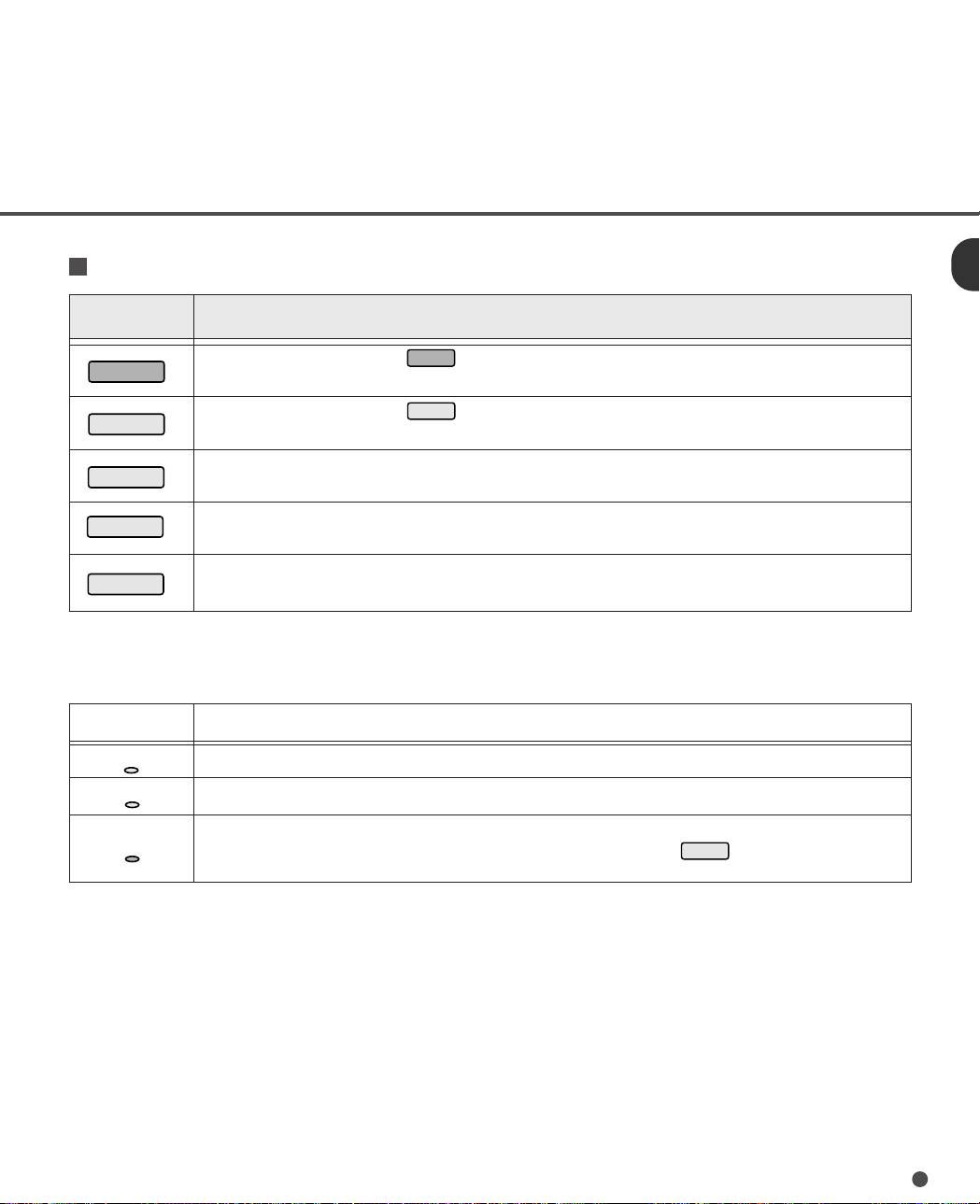
How to set the endorser ON (or OFF)
When you use the endorser, you must set the endorser on as follows:
1 While pressing
of the scanner. Then the LCD displays
SETUP MODE initial screen. <Screen 1>
2 Press
Mode 1
Mode 1
, turn on the power
8 times to display EN-
<Screen 1>
<><>SETU P M O D
DORSER INITIAL screen. <Screen 2>
Then press
Mode 2
. If “ON” is displayed,
the endorser is already turned on.
<Screen 3>
<Screen 2>
3 If “OFF “ is displayed, press
until “OFF” blinks. Then press
turn the endorser on. <Screen 3>
Mode 1
Mode 2
to
<><>SETU P M O D
DORSE R INITIAL
EN
Go to 5 to store the settings in EEPROM.
Go to 6 and 7 to close the job.
<Screen 3>
DORSE R VALUE
EN
✳ON 00001
(Blinking)
NOTE
Set the endorser on only when you use it, or characters may be printed on
every scanned document.
E
E
6-2
Page 67

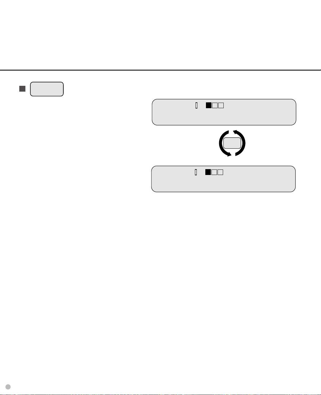
How to set the initial number
Stop
The initial number is the number which the scanner starts printing or returns after the reset of the print
number.
4 In Screen 3, press
Mode 1
until the number
you want to display appears.
(Ex. The initial number is 5 in Screen 4.)
5 To store the settings in EEPROM, press
Mode 1
until ✳ blinks. Then press
Mode 2
change the LCD display into Screen 5.
Press
Mode 2
to store the settings. Screen 6
appears for about 3 seconds.
6 Press
Mode 1
and
Mode 2
at the same time
to return to ENDORSER INITIAL screen.
<Screen 2>
7 Press
to return to the initial setting to
read.
to
<Screen 4>
DORSE R VALUE
EN
✳ON 00050
<Screen 5>
OM WR I T
R
EP
(Mode2
<Screen 6>
O M W r i t
R
EP
(Blinking)
E
?E
W r i t e )
i
nEg!!
6-3
Page 68

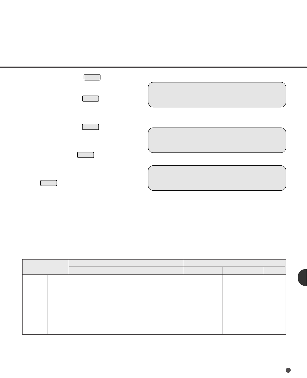
How to select the print number reset method
Mode 2
Mode 1
You can choose whether to reset or not the print number when “HOPPER EMPTY” is detected.
8 In Screen 1, press
Mode 1
9 times to
<Screen 7>
display ENDORSER RESET METHOD
screen. <Screen 7>
9 Press
Mode 1
time you press
Mode 2
to display Screen 8. Press
to display “ON” or “OFF”. Each
Mode 1
, “ON” and “OFF”
appear alternately. Select “ON” to reset
the print number when “HOPPER
EMPTY” appears and select “OFF” not to
EN
<Screen 8>
<><>SETU P M O D
DORSE R RESET
P
EM T Y R
-
OP
reset. The setting is automatically stored
in EEPROM.
10 Press
Mode 2
to return to Screen 7.
Go to 7 to close the job.
How to reset the print number manually
You can reset the print number to the initial number using the operator panel.
11 In Screen 1, press
Mode 1
10 times to
display ENDORSER RESET screen.
<Screen 9>
12 Press
Mode 2
to display Screen 10 where
“OFF” and the current print number are
displayed.
If you want to reset the number, press
. And you can see Screen 11 for 3
seconds. If you do not want it, press
to go Screen 9.
Go to 7 to close the job.
<Screen 9>
<Screen 10>
S
RE
N
M
o
-
<Screen 11>
S
RE
<><>SETU P M O D
DORSE R RESET
EN
ET VALUE
o
ET
de1
Y
F
inish
e
E
ME
THOD
E
SHET
N
O
E
00001
de2
M
o
s
-
!
00001
!
6-4
Page 69

Mode 2
How to reset the print head life counter
Mode 2
Start
You must reset the print head life counter when you replace the print head.
13 In Screen 1, press
Mode 1
11 times to
<Screen 12>
display INK RESET screen. <Screen 12>
<><>SETU P M O D
14 Press
want to reset the counter, press
And you can see Screen 14 for 3 seconds.
If you do not want it, press
Screen 12.
Go to 7 to close the job.
to display Screen 13. If you
Mode 2
.
Mode 1
to go
<Screen 13>
N
o-
M
de1
o
INK
INK
<Screen 14>
RE
F
ET
S
How to test the printing using the operator panel
You can check the print result as follows:
15 Turn the endorser on by following the
procedure of “page 6-2, How to set the
endorser ON (or OFF)”.
16 Turn the power of the scanner on while
Mode 2
pressing
. The LCD displays MAINTENANCE MODE initial screen.
<Screen 15>
<Screen 15>
T
TES
<<C
x x : S T ART
R
E
R
E
Y
s
e
inish
M
ODEE
E
SET
SET
M
o
-
!
!
>
de2
>
17 Press
once, then press
Mode 1
once.
Place a document on the stacker, then
press
NOTE
.
•The scanner prints 5-digit numbers counting in increment of one from the
initial number.
•Before pressing
Start
you can set the document size, resolution and so
on (See Chapter 3).
6-5
Page 70

6-6
Page 71

CHAPTER
7
SETUP MODE
This chapter describes the setup mode of the scanner.
Activating the Setup Mode
Contents of the Setup Mode
Page 72

Activating the Setup Mode
Mode 1
Mode 1
Mode 1
This section describes how to activate the setup mode.
1 Turn the power of the scanner on while
pressing
Screen 1.
2 After a while, LCD displays SETUP
MODE initial screen. <Screen 2>
(In case of M3099EX/EH, pressing
Screen 2.)
3 Press
SETUP MODE. Press
the readable status.
(In case of M3099GX/GH, Screen 3
indicates the readable status.)
after turning power on displays
. The LCD displays
to select the menu of
Stop
to go to
<Screen 1>
<Screen 2>
<Screen 3>
ming-up N ! T!
raW
<><>SETU P M O D
S
canner Re dy
o
E
a
7-1
Page 73

Contents of the Setup Mode
This section describes the contents of the setup mode.
The setup mode can be classified into 17 (M3099EX/EH) or 18 (M3099GX/GH) types.
Mode Setup type
1 Setting double feed detection
2 Setting IPC-2 pre-set
3 Reset of abrasion counter
4 Setting buzzer
5 Setting pre-pick
6 Adjusting LCD contrast
7 Setting pick speed
8 Setting initial value of endorser
9 Setting reset method of endorser reset
10 Reseting of endorser
11 Reseting of ink counter
12 Setting RS-232C transfer rate *1
13 Setting SCSI-ID *2
14 Setting Product-ID *2
15 Setting picking start time
Contents
Set in EEPROM whether double feed detection is done or not.
Set in EEPROM the pattern No.of IPC-2 pre-set mode.
Reset the abrasion counter after Belt/Roller are exchanged.
Set in EEPROM whether the buzzer function is on or off.
Set in EEPROM whether pre-picking is done for fast reading or not.
Set in EEPROM the LCD contrast.
Set in EEPROM whether pick speed is fast or slow.
Set the initial number. The set value can be stored in EEPROM.
Set in EEPROM whether the number is reset by hopper empty detection.
Reset the number to the initial value.
Reset the ink counter after the print head is replaced.
Set the transfer rate in EEPROM. (1200/2400/4800/9600).
Set the SCSI-ID. (0-7)
Set the Product-ID. (M3096G/M3099G/M3099GH)
Set in EEPROM the time from when the hopper empty sensor is blocked
in manual mode until picking begins.
16 Setting picking time
17 Setting time-out limit
18 Setting hopper time
19 Setting heater control
7-2
Set the time from when picking begins until the SF1 sensor is blocked by
paper.
Set the time from when a command is issued in manual mode until paper
is actually detected.
Set the time from when Start Command Time-out limits until hopper table
is lowered.
Set in EEPROM whether heater control is on or off.
*1 Available for only M3099EX/EH.
*2 Available for only M3099GX/GH.
Page 74

Setting double feed detection
Mode 2
Mode 1
Mode 1
When you set the using of double feed detection, you must set as follows:
4 In Screen 2, press
Mode 1
once to
display DOUBLE FEEDCHECK screen
<Screen 4>.
5 Press
Mode 2
to display Screen 5.
Select “ON” to set the error detection
when the double feed occurs.
Each time
is pressed, “ON” and
“OFF” appear alternately.
6 Press
to display Screen 6.
This screen detemines how to detect the
double feed.
“1” means the method by comparing with
the length of the first paper.
“2” means the method by the output of
document detection sensor in addition to
“1”.
In Screen 6, press the
Mode 2
until the
nurmber you select appears.
7 Press
to display Screen 7.
This screen detemines the length to
compare with the paper based on.
If you choose “1” or “2” set “15 mm”,the
double feed is detected when the
scanned paper length is 15 mm longer
than the first paper.
In Screen 7, press the
Mode 2
until the
number you want to select appears.
(You can choose 10,15, or 20 mm. The
default is 15 mm.)
<Screen 4>
<Screen 5>
OFF
(Blinking)
<Screen 6>
OFF
<Screen 7>
OFF
<><>SETU P M O D
UB FE
UB FE
EHDO ECL
EHDO ECL
E
D
E
D
1
UB FE
EHDO ECL
E
D
1
(Blinking)
UB FE
EHDO ECL
E
D
1
E
C
C
C
C
K
K
m
m
1
5
K
m
m
1
5
K
m
m
1
5
(Blinking)
7-3
Page 75

8 Press
Mode 1
Mode 2
Mode 1
and
Mode 2
at the same
time to display Screen 4. The settings
are stored in EEPROM.
When you close, press
Stop
.
Mode Details
ON/OFF “OFF” is default setting.
1 “1” is default setting.
This mode is used when a batch of documents whose length are same is scanned.
When a document with tears and wrinkles is scanned, the scanner may also fail to
detect the double-feed.
2 This mode is used when a batch of documents whose length and thickness are same is
scanned.
However, when a thin document is scanned, the scanner may fail to detect the doublefeed rarely.
\In this case, please test scanning of a thin document in advance.
Setting IPC-2 pre-set mode
When you set the using of IPC-2 pre-set mode, you must set as follows:
7-4
1 AT Screen 2, press
Mode 1
twice to
go to the IPC-2 SET screen. <Screen 8>
2 Press
to see Screen 9 or 10.
If “No” is displayed, IPC-2 pre-set mode
is not used.
If pettrn number (“1”-“5”) is displayed,
IPC-2 pre-set mode is used.
“No” or number status flips each time you
press
.
(The default setting is “No”.)
<Screen 8>
<Screen 9>
<><>SETU P M O D
IPC-2 SET
IPC-2 SET
No
E
Page 76
3 If you press the
Stop
Mode 2
at Sccreen 9,
you return to screen 8.
The setting is stored to EEPROM.
If you press the
Mode 2
at screen 10,
you go to screen 11. (Screen 12 in case
of M3099GH/GX)
<Screen 10>
IPC-2 SET
X
4 If you press the
Mode 1
at screen 11/12,
IPC-2 pre-set mode can be not used.
<Screen 11>
Panel/Host Set Ignore
Also the setting is changed to “No”
obligatory and stored to EEPROM. If
you press the
Mode 2
at screen 11/12,
IPC-2 pre-set mode can be used and the
setting number is stored to EEPROM.
When you close the setup mode, press
.
No-Mode 1 Yes-Mode 2
<Screen 12>
Host Set Ignore
No-Mode 1 Yes-Mode 2
<Classification of user’s paper>
User’s paper are classified in line-art scanning as follows:
The horizontal axis shows the background density/color of paper.
The vertical axis shows the density of charcter/ line.
Background density
Character
density
Normal
↑
Normal← →Dark
q:Normal background
and character.
e:Dark background
and normal-density
character.
Red Green Blue
Background color
↓
w:Normal background
Light
q - t are the pattern number set in setup mode.
and light character.
r:Light character
on red paper.
t:Light character
on green paper.
7-5
Page 77

NOTE
• For patterns “1” to “5” when the power is turned on
Scanner checks that IPC-2 for front/back sides are installed during initialization.
If IPC-2 for either the font or back side is not installed, the scanner regards as no setting obligatory and
changes the memory of EEPROM.
• When IPC-2 pre-set is executed in setup mode
Scanner checks that IPC-2 for front/back sides are installed when the scanner enters in IPC-2 pre-set.
If IPC-2 for either the front or back side is not installed, the scanner does not enter in IPC-2 pre-set.
• When IPC-2 pre-set mode is executed
When IPC-2 pre-set mode is executed in online mode, the reading parameter is valid or invalid
(Host setting is invalid) as follows:
Reading parameter
Valid
Invalid
Valid
Invalid
Reading
mode
●●
DTC
●●
Tranfer
mode
●●
Size
●●
Transfer
rate
●●
Portrait/
Landscape
●●
Resdution
●●
Reading parameter
Picking
●●
Document
Start of
reading
●●
selection
●●
Density
●●
r patterns
●●
Line-art
/ Photo
●●
Contrast
●●
Halftone
●●
Automatic
separation
●●
7-6
Valid
Invalid
Conversion
●●
Sharpness
●●
Reading parameter
Outline
extraction
●●
Overlay
●●
Simplified
DTC
●●
Zooming
●●
Page 78

Stop
Reset of abrasion counter
Stop
When you reset the abrasion counter, you must set as follows:
1 In Screen 2, press
Mode 1
3 times to
<Screen 13>
display PAPER COUNT RESET screen.
<Screen 13>
2 Press
Mode 2
to display Screen 14.
You may see current paper count.
<Screen 14>
PA
If you want to reset the count,press
Mode 2
. And you can see Screen 15 for 3
seconds.
If you do not want it, press
Mode 1
to go to
Screen13.
3 When you close the setup mode, press
<Screen 15>
RE SET
No-Mode 1
S
RE
.
Setting buzzer
When you set the using of buzzer, you must set as follows:
1 In Screen 2, press
display BUZZER SET screen.
<Screen 16>
2 Press
Mode 2
to display Screen 17.
Select “ON” to ring the buzzer when an
error occurs. Each time
pressed, “ON” and “OFF” appear
alternately. The setting is stored in
EEPROM automatically.
3 Press
Mode 2
to return to Screen 16.
When you close the setup mode, press
.
Mode 1
4 times to
Mode 1
is
<Screen 16>
<Screen 17>
<><>SETU P M O D
C
PE
ET
R
C
F
inish
OU
OU N
Y
N
T
e
T
s
!
<><>SETU P M O D
P
RE
BU
P
Z
C
KSEIT
E
RSEZT
O
N
E
RE S
M
-
!
E
ET
654321
d e 2
o
00000
7-7
Page 79

Setting pre-pick
Stop
Stop
When you set the using of buzzer, you must set as follows:
1 In Screen 2, press
Mode 1
5 times to
<Screen 18>
display PREPICK SET screen.
<Screen 18>
2 Press
Mode 2
to display Screen 19.
Select “ON” to set the pre-picking when
the document is fed. Each time
Mode 1
is
<Screen 19>
pressed, “ON” and “OFF” appear alternately. The setting is stored in EEPROM
automatically.
3 Press
Mode 2
to return to Screen 18.
When you close the setup mode press
.
Adjusting LCD contrast
When you adjust the LCD contrast, you must set as follows:
1 In Screen 2, press
display LCD CONTRAST screen.
<Screen 20>
2 Press
Mode 2
to display Screen 21. As
the number of “■” increases, the LCD
contrast gets darker.
3 In Screen 21, the LCD contrast is set to
one of the 16 steps. Each time
is pressed, the number of “■” increases. When all fields are filled by
“■”, next pressing
“■■” (The lightest contrast).
4 Press
Mode 2
to display Screen 20. The
settings are stored in EEPROM.
Mode 1
Mode 1
starts from all
6 times to
<Screen 20>
Mode 1
<Screen 21>
<><>SETU P M O D
P
RE
P
RE
<><>SE
P
P
T
C
KSEIT
C
KSEIT
O
N
U P MO
CODC ASLTNTR
C
C
L
D
ON
TRAST
E
DE
5 When you close the setup mode, press
.
7-8
Page 80

Setting pick speed
Mode 2
Mode 1
Mode 2
Stop
When you set the pick speed, you must set as follows:
1 In Screen 2, press
display PICK SPEED SET screen.
<Screen 22>
2 Press
to display Screen 23. (The
default setting is “FAST”.)
Mode 1
7 times to
<Screen 22>
P
<><>SE
I
T
KESP SECTED
If “FAST” is displayed, the pick speed is
fast. If “SLOW” is displayed, the pick
speed is slow.
Each time
and “SLOW” appear alternately. The
setting is stored in EEPROM automatically.
3 Press
When you close the setup mode, press
is pressed, “FAST”
to return to Screen 22.
<Screen 23>
P
AST SLO W
F
(Blinking)
K
I
S
.
Setting initial value of endorser
Before setting, see page 6-2, “Chapter 6 ENDORSER, Panel Operation”.
• The use of Endorser (ON/OFF)
The default setting is “OFF” (Endorser is not used.)
U P MO
ED
P
E
DE
SECT
• The initial number
The default setting is “00000”.
The selectable range is from 00000 to 65535.
NOTE
If the specified value is equal or grater than 65536, returning to SETUP menu will be failed.
7-9
Page 81

<Method of Increment >
When the initial value is “00001”.
00001 (1 Page)
00002 (2 Page)
65534 (65534 Page)
65535 (65535 Page)
NOTE
•If “depending on operator panel” is not set by host machine, you can not change the setting.
•When “depending on operator panel” is selected, printing starts at the position 20 mm back from
the top end of the back side.
Setting reset method of endorser
Before setting, see page 6-2, “Chapter 6 ENDORSER, Panel Operation”.
The default setting is “ON” (The print number will be reset when HOPPER EMPTY is detected.)
Resetting of endorser
Before setting, see page 6-2, “Chapter 6 ENDORSER, Panel Operation”.
Resetting of ink counter
Before setting, see page 6-2, “Chapter 6 ENDORSER, Panel Operation”.
7-10
Page 82

Setting RS-232C transfer rate (M3099EX/EH)
Mode 2
Mode 2
Stop
Mode 2
Mode 2
Stop
When you set RS-232C transfer rate, you must set as follows:
1 In Screen 2, press
display RS-232C BAUD screen.
Mode 1
12 times to
<Screen 24>
<Screen 24>
<><>SETU P M O D
2 Press
to display Screen 25.
(The default setting is 4800 bps.)
3 In Screen 25, press
you want to select blinks.
4 Press
to display Screen 24.
Mode 1
until the rate
<Screen 25>
<><>SETU P M O D
The settings are stored in EEPROM.
5 When you close the setup mode, press
.
Setting SCSI-ID (M3099GX/GH)
When you set the picking start time, you must set as follows:
1 In Screen 2, press
display SCSI-ID SET screen.
<Screen 26 >
2 Press
(The default setting is “5”.)
Mode 1
12 times to
to display Screen 27.
<Screen 26>
<><>SETU P M O D
RS
0069
S
2
:48
(Blinking)
C
E
2
BAUD3
C
E
00:
24001200
:
E
I
DSEST
-I
3 In Screen 27, press
SCSI-ID. Each time
Mode 1
Mode 1
to change
is pressed,
SCSI-ID changed from 0 to 7.
4 Press
to display Screen 26.
The settings are stored in EEPROM.
5 When you close the setup mode, press
.
<Screen 27>
I
S
C
DSEST
-I
5
7-11
Page 83

Setting Product-ID (M3099GX/GH)
Mode 2
Mode 2
Stop
Mode 2
Mode 1
Stop
When you set Product-ID, you must set as follows:
1 In Screen 2, press
PRODUCT-ID SET screen. <Screen 28>
2 Press
Mode 1
13 times to display
to display Screen 29.
<Screen 28>
(The default setting is “M3099GH” in case of
M3099GH and “M3099G”in case of
M3099GX.)
3 In Screen 29, press
ID. Each time
Mode 1
to select Product-
Mode 1
is pressed, M3099G,
M3099GH or M3096G apear in case of
M3099GH, and M3099G or M3096G at each
time you press
Mode 1
in case of M3099GX.
<Screen 29>
4 Press
to display Screen 28.
The settings are stored in EEPROM.
5 When you close the setup mode, press
.
Setting picking start time
When you set the picking start time, you must set as follows:
1 In Screen 2, press
for M3099GX/GH) to display PICK START
TIMER screen. <Screen 30 >
2 Press
(The default setting is 1 second.)
Mode 1
13 times (14 times
to display Screen 31.
<Screen 30>
<><>SETU P M O D
RP
RP
ODU
-
T
ID
C
-
T
ID
C
ODU
<><>SETU P M O D
KS
CIP
TAR
TTIER
E
S
T
E
S
T
E
XX
XXX
X
E
M
7-12
3 In Screen 31, press
want to change blinks. Then press
Mode 1
until the digit you
Mode 2
until the value you want to select appears.
(The selectable range is from 0.2 to 29.8
seconds in steps of 0.2 seconds.)
4 Press
and
Mode 2
at the same time to
display Screen 30.
The settings are stored in EEPROM.
5 When you close the setup mode, press
.
<Screen 31>
KS
CIP
XX
(Blinking)
TAR
.
XS
TTIER
M
Page 84

Setting picking time
Mode 2
Mode 1
Stop
Mode 2
Mode 2
Mode 1
Stop
When you set the picking time, you must set as follows:
1 In Screen 2, press
Mode 1
14 times (15
times for M3099GX/GH) to display PICK
TIMER screen. <Screen 32>
2 Press
to display Screen 33.
(The default setting is 2 seconds.)
3 In Screen 33, press
Mode 1
until the digit
you want to change blinks. Then press
Mode 2
until the value you want to select
appears. (The selectable range is from 0.5
to 99.5 seconds in steps of 0.5 seconds.)
4 Press
and
Mode 2
at the same time
to display Screen 32.
The settings are stored in EEPROM.
5 When you close the setup mode, press
.
Setting time-out limit
1 In Screen 2, press
(16 times for M3099GX/GH) to display
TIME-OUT SET screen. <Screen 34>
Mode 1
15 times
<Screen 32>
<><>SETU P M O D
<Screen 33>
<><>SETU P M O D
<Screen 34>
PIC
XX
(Blinking)
K
.X
T
IM
S
E
R
E
E
2 Press
to display Screen 35.
(The default setting is 30 seconds.)
3 In Screen 35, press
Mode 1
until the digit
you want to change blinks. Then press
until the value you want to select
appears. (The selectable range is from 1 to
1999 seconds in steps of 1 second.)
4 Press
and
Mode 2
at the same time
to display Screen 34. The settings are
stored in EEPROM.
5 When you close the setup mode, press
.
<><>SETU P M O D
<Screen 35>
IME
T
IME
T
XXXX S
(Blinking)
E
-
O
-
O
S
U
T
U
T
T
E
S
T
E
7-13
Page 85

Mode 2
Mode 1
Mode 2
Setting hopper time
Mode 2
Mode 1
Stop
When you set the picking time, you must set as follows:
1 In Screen 2, press
for M3099GX/GH) to display HOPPER
Mode 1
16 times (17 times
<Screen 36>
TIMER screen. <Screen 36>
2 Press
to display Screen 37.
(The default setting is 7 seconds.)
3 In Screen 37, press
want to change blinks. Then press
Mode 1
until the digit you
Mode 2
<Screen 37>
until the value you want to select appears.
(The selectable range is from 0 to 30 seconds
in steps of 1 second.)
4 Press
and
Mode 2
at the same time to
display Screen 36. The settings are stored in
EEPROM.
5 When you close the setup mode, press
.
Setting heater control
When you set the heater control, you must set as follows:
1 In Screen 2, press
for M3099GX/GH) to go to the HEATER
CONTROL screen. <Screen 38>
Mode 1
17 times (18 times
<><>SETU P M O D
H
OPPER
H
OPPER
(Blinking)
XX
TIME R
TIME R
S
E
7-14
2 Press
to display Screen 39. If “ON”
is displayed, the heater control will be done.
If “OFF” is displayed, warming-up will finish
within 30 seconds, if necessary. When the
heater is broken, please set “OFF”. Each
time
is pressed, “ON” and “OFF”
appear alternately. The setting is stored in
EEPROM automatically.
3 Press
you close the setup mode, press
to display Screen 38. When
Stop
<Screen 38>
<><>SETU P M O D
T
H
ER
E
E
T
ONA
C
ROL
<Screen 39>
T
H
.
ER
E
ON
T
ONA
C
ROL
Page 86

GLOSSARY OF TERMS
A4 size
A standard paper size used in Japan and other countries. Paper size is 210 x 297 mm (8.25 x 11.6 inches).
Abrasion counter
Indicates when belts/rollers should be replaced. The number of read document accumulates until an
operator resets the counter. It should be reset when consumables are replaced.
ASCII
The acronym for American Standard Code for Information Interchange.
ASCII is a set of 256 codes (numbered 0 to 255) used to communicate information between a computer
and another device such as scanner.
Automatic separation
The image processing method to detect the difference between text and photos and choose the threshold
accordingly. Automatic separation allows the scanner to switch between line mode and half tone mode
in one pass.
Automatic start mode (<–> manual start mode)
In this mode the reading operation is activated only by START command.
Back-side reading = Back-side scanning
Refers to reading the back-side of the document, specifically in Duplex reading mode.
Bit
The smallest unit of information in computer memory. A bit is a single digit, either a 1 or a 0, in the binary
numbering system.
Eight bits equal one byte.
Density
Refers to a measurement of the depth of the display in this manual.
Dither
Technique for producing halftone images representing the entire grayscale using two pixel levels black
and white.
GL-1
Page 87

Double feed detection
A function which detects the status when multiple sheets are fed in the transport unit.
dpi
Dots per inch.
Drop-out color
A color which is used to the document but does not appear in the read image.
Duplex reading mode
Both sides of the document are read in this mode.
Endorser
The unit for printing characters before or after scanning. These character may be used for collation of the
documents and the image data. (See Chapter 6 ENDORSER.)
Endorser value
The number printed by the endorser.
Equipment Error
An error that is not recoverable by operator. Call CE.
Error diffusion
High-quality halftone (pseudo-grayscale) image production based on black-and-white pixel binarization.
A pixel’s optical density and that of adjacent pixels are summed, with black pixels relocated in their order
of density as they relate to adjacent pixels.
The purpose of this technique is to minimize the average error between read and printed densities.
Density data for adjacent pixels is modified by diffusing errors on the objective pixel into several pixels,
which are then binarized. This maintains high grayscale levels and resolution during reading, while
suppressing more patterns by dotted halftone images such as newspaper photo graphs.
Filtering
The quality of images written in pencil or ball-pointed pen and read depends on the reflective light
characteristics of the ink or lead.
Dropped pixel’s may produce out lines, gaps or thin, barely connected lines due to even optical density.
Filtering detects areas lighter than their surroundings and increases their density to improve image clarity.
GL-2
Page 88

Front-side reading = Front-side scanning
Refers to reading the front-side of the document, specifically in Duplex reading mode.
Halftone processing
Used to reproduce a photograph which includes a shade as an image composed of dots, namely a binary
image. Dithering and error diffusion processing are examples of the halftone processing.
Heater control
The heater is set to ON or OFF to keep the lamp at a constant temperature and stabilize the intensity of
the lamp.
Hexadecimal
A base-16 numbering system(also commonly referred to as hex numbers). Since a base-16 system
requires 16 digits, numbers 0 through 9 and letters A through F are used. It is convenient to express binary
numbers in hexadecimal because fewer digits are required.
Image emphasis
Density is decreased for lighter but not completely white areas adjacent to black areas. Weakening this
emphasis eliminates spot noise or produces softened images.
Image processing
An image is read with specified parameters.
Initial screen
A screen displayed when the power is turned on or when reading is activated by the command from the
host computer.
INK EMPTY
A warning issued when the number of dots printed by the print head exceeds a specified value. It indicates
that the life of the print head is near to the end and the replacement of the print head is soon necessary.
Interface
The connection that allows communication from one part of a system to another. For example, electrical
signals are transferred between the computer and scanner over an interface cable.
GL-3
Page 89

Inversion (Reverse-image reading)
In reverse-image reading, data is changed from black to white and vice versa.
IPC-2 pre-set mode
While reading binary images, it is necessary to set the scanner according to the quality of the sheet to be
read. In this mode these settings can be performed in advance by corresponding each setting to a pattern
number.
IPC II
Image processing option of this scanner.
IRAS
Initialization of the hardware.
Landscape
A document is transported and read with the long side vertical to the moving direction.
Letter size
A standard paper size used in the U.S.A. and other countries. Paper size is 8-1/2 x 11 inches (215.9 x
279.4 mm).
Linedrawing mode
Selecting linedrawing mode makes threshold and contrast settings effective but prevents brightness from
being set. The specified threshold value determines whether black or white pixels are scanned. Linedrawing mode is therefore appropriate for scanning text and line art images.
Manual Feed mode = Manual Mode
Requires the operator to feed each document manually to the hopper table.
Manual start mode (<–> automatic start mode)
The reading operation is activated by pressing the START button in this mode.
Mirror image
The read image is symmetrically flipped to produce a mirror image of the original detected in the main
scanning direction.
GL-4
Page 90

Noise removal
Isolated noise from an image appearing as black spots in white areas and voids in black areas is removed
to improve image quality.
Operator panel
A panel containing the scanner indicators and buttons. The operator panel is used to control scanner
operations such as loading document, selecting features, and changing setup options.
Outline extraction
The boundary between black and white areas is traced and the outline extracted for closed areas.
PAPER JAM
A warning informing the user that document is jammed in the transport unit, or that transportation is
disabled because the transport unit is slippery. This warning also appears when a double fed is detected.
Photograph mode (White level follower ON)
Selecting photograph mode makes brightness and contrast settings effective but prevents the threshold
from being set. With photograph mode, the darkness of image corresponds to the black-pixel density,
making it suitable in scanning images such as photographs having gradations.
Photo mode = photograph mode
A photograph is read properly in this mode.
Picking start time
The period from the manual insertion of the document until picking starts after the document passes the
hopper empty sensor.
Picking time
The period from the start of picking until the document reaches SF1 sensor. Specify a little longer picking
time for the document with a large friction factor.
Pick speed
A speed when a document is picked. Set the pick speed to SLOW to prevent JAM or MISS PICK.
Portrait
A document is transported and read with the long side parallel to the moving direction.
GL-5
Page 91

Pre-picking
A setting in which a document to be read next is placed at the front of the reading unit while the previous
document is read. Setting the pre-picking makes the process speedier.
Print head
A cartridge located in the endorser (optional). It contains the ink reservoirs and creates the ink droplets.
It is replaceable by operator.
Print head life counter = ink counter
A counter which accumulates the number of the printed dots. When the accumulated number exceeds
a specified value, “INK EMPTY” appears.
Print number reset method
Determines whether or not to reset the number printed by the endorser to zero. This scanner can be set
so that the number is reset when the hopper empty is detected.
Readable status
A status when the power is turned on or when reading is activated by the command from the host computer.
Reading counter
Indicates the total number of read document from reading start until the hopper becomes empty.
Read operation
Refers to the reading operation including Simplex reading and Duplex reading.
Reset method of endorser
Refer to “Print number reset method”.
RS-232C interface
A type of serial interface. See Serial interface.
SCSI-ID
Used to specify a particular SCSI device when the initiator selects a target or the target re-connects to the
initiator.
GL-6
Page 92

Serial interface
A standard computer interface. Information is transferred between devices over a single wire (although
other wires are used for control).
With a serial interface, an interface cable greater than 3 meters (10 feet) can be used. This is often
necessary in networking environments, where the scanner may be shared.
SETUP mode
In this mode, users can view or set a variety of function in Off-line.
SFI sensor
The document detection sensor. It detects the light that transmits the paper. It also detects the double
feed error.
Simplex reading mode
Only the front side of the document is read in this mode. Place the documents face-up at the center of
the hopper table.
Smoothing
Smoothing eliminates jaggies from slanted lines and curves. Irregular convexities are deleted and
irregular concavities filled in. This is useful in OCR applications, for example.
Start command time-out
Occurs if START command does not arrive before the specified time after reading the previous document
is complete. In this case the hopper table is lowered.
Temporary Error
An error that is recoverable by operator.
Terminator
Devices with SCSI interface are daisy-chained. A resistor that includes terminal circuits needs to be
placed at both ends of a cable when devices are daisy-chained.
GL-7
Page 93

GL-8
Page 94

INDEX
A3 1-6
A
A4 1-6
Abrasion counter 1-9
Activating the Setup Mode 7-1
ADF mode 1-6
Adjusting LCD contrast 7-8
Ambient condition 5-1
Arrangement 1-4
Assemblies 1-3
Back-side reading mode 1-6
B
Belt 5-3
Belt ASY 5-3
Button
/LED Function 1-5, 1-11
Specification (M3099GX/GH) 3-17
Specification and Reading Mode Setting (M3099 EX/EH) 3-2
Buzzer functions 1-14
Cable Connection 2-4
C
Checking the Components 1-1
Connecting
the interface cable 2-5
the power cable 2-4
Consumables 5-3
Consumable kit 1-1
Contents of the Setup Mode 7-2
Conventions iii
Density 1-6, 1-7
D
Density button 3-4, 3-10, 3-14
Dimentions 5-1, 5-2
Document
button 3-7, 3-12, 3-14
orientation 1-6
Quality 4-2
Size 4-1
Document type 4-2
Double letter 1-6
Duplex
button 3-2
reading mode 1-7
(back-side) reading mode 3-14
(front-side) reading mode 3-10
Endorser 5-4, 6-1
E
Equipment error 1-14
Fedding direction 4-1
F
Fine paper 4-2
Front-side reading mode 1-6
Front/Back button 3-2
Halftone
H
I
button 3-6, 3-11, 3-14
processing 1-6, 1-7
Heat capacity 5-1
Hopper 1-2
Image processing option 1-6, 1-7
IMPORTANT NOTE TO USERS i
Input power 5-1
Inspection 2-2
Installation Specifications 5-1
IPC-2 pre-set mode 1-9, 1-13
IN-1
Page 95

Label
L
M
O
A 2-2
B 2-3
C 2-3
D 2-3
Lamp 5-3
Landscape 1-6
Landscape button 3-5, 3-11
LCD 1-4, 1-10
LCD Display 1-6, 1-12
LED 1-5, 1-11
Legal 1-6
Letter 1-6
Manual
button 3-8, 3-12, 3-17
mode 1-6
Mode
1 button 3-17
2 button 3-17
OCR paper 4-2
Operation Status 1-8
Operator’s Guide 1-1
Operator
panel 1-4, 1-10, 3-1
Panel (M3099 EX/EH) 1-4,
Panel (M3099 GX/GH) 1-10
Option 5-4
Pad 5-3
P
Panel Operation 6-2
Paper weight 4-2
Perface ii
Photo/linedrawing mode 1-6, 1-7
Pick roller 5-3
Plain paper 4-2
Portrait 1-6
Power
cable 1-1
consumption 5-1
switch 2-4, 3-1
Precautions 2-1, 4-2
Print Head 5-3
Reading
R
counter 1-8,
counter and Abrasion counter 1-12
mode 1-6
Read side 1-6
Reset of abrasion counter 7-7
Resetting
of endorser 7-10
of ink counter 7-10
Resolution 1-6
Resolution button 3-4, 3-10
Roller ASY 5-3
IN-2
Page 96

Scanner 1-1
S T
Screen transition 3-9, 3-13, 3-15
Setting
buzzer 7-7
double feed detection 7-3
heater control 7-14
hopper time 7-14
initial value of endorser 7-9
IPC-2 pre-set mode 7-4
pick speed 7-9
picking time 7-13
picking start time 7-12
pre-pick 7-8
product-ID 7-12
reset method of endorser 7-10
RS-232C transfer rate 7-11
SCSI-ID 7-11
time-out limit 7-13
Simplex
(front-side) reading 1-6
(front-side) reading mode 3-3
reading mode 1-6
Size 1-6
Size button 3-3, 3-10
Specifications 6-1
Stacker 1-2
Start button 3-16, 3-17
Stop button 3-16, 3-17
U
W
Terminator 1-1
Temporary
error 1-14
Lable (An Example) 2-3
Turning
the Power On 3-1
the power switch off 2-4
Types 1-2
Units 1-2
Units and Assemblies 1-2
Weight 5-1
IN-3
Page 97

IN-4
Page 98

Page 99

Page 100

 Loading...