

Page 1

M3097G
IMAGE SCANNER
50FH5043E>02
OEM MANUAL
Page 2

REVISION RECORD
Edition
01 Apr., 1993
02 Feb., 1996 Gray scale added
Date published Revised contents
Specification No.: 50FH5043E
The contents of this manual is subject to change
without prior notice.
All Rights Reserved,
Copyright ” 1993, 1996 FUJITSU LIMITED
i !!
Page 3

This page is intentionally left blank.
!!ii
Page 4

CONTENTS
page
CHAPTER 1 GENERAL . . . . . . . . . . . . . . . . . . . . . . . . . . . . . . . . . . . . . . . . . . . . . . 1 $ 1
1.1 General . . . . . . . . . . . . . . . . . . . . . . . . . . . . . . . . . . . . . . . . . . . . . . . . . . . . . . . . . 1 $ 1
1.2 Features . . . . . . . . . . . . . . . . . . . . . . . . . . . . . . . . . . . . . . . . . . . . . . . . . . . . . . . . . 1 $ 3
1.3 Part Names and Functions . . . . . . . . . . . . . . . . . . . . . . . . . . . . . . . . . . . . . . . . 1 $ 4
1.3.1 Exterior view of image scanner . . . . . . . . . . . . . . . . . . . . . . . . . . . . . . . . . . . . 1 $ 4
1.3.2 Functions of each part . . . . . . . . . . . . . . . . . . . . . . . . . . . . . . . . . . . . . . . . . . . . 1 $ 5
CHAPTER 2 SPECIFICATIONS . . . . . . . . . . . . . . . . . . . . . . . . . . . . . . . . . . . . . . 2 $ 1
2.1 Function Specifications . . . . . . . . . . . . . . . . . . . . . . . . . . . . . . . . . . . . . . . . . . . 2 $ 1
2.2 Physical Specifications . . . . . . . . . . . . . . . . . . . . . . . . . . . . . . . . . . . . . . . . . . . . 2 $ 3
2.3 Optional Circuit Feature . . . . . . . . . . . . . . . . . . . . . . . . . . . . . . . . . . . . . . . . . . 2 $ 4
2.3.1 Image processing circuit ¬ (IPC ¬) . . . . . . . . . . . . . . . . . . . . . . . . . . . . . . . . 2 $ 4
2.3.1.1 Dynamic threshold function . . . . . . . . . . . . . . . . . . . . . . . . . . . . . . . . . . . . . . . 2 $ 4
2.3.1.2 Image processing function . . . . . . . . . . . . . . . . . . . . . . . . . . . . . . . . . . . . . . . . . 2 $ 5
CHAPTER 3 CONFIGURATION . . . . . . . . . . . . . . . . . . . . . . . . . . . . . . . . . . . . . . 3 $ 1
3.1 Outer Dimensions . . . . . . . . . . . . . . . . . . . . . . . . . . . . . . . . . . . . . . . . . . . . . . . . 3 $ 1
3.2 Circuit Configuration . . . . . . . . . . . . . . . . . . . . . . . . . . . . . . . . . . . . . . . . . . . . . 3 $ 3
3.3 Operator panel . . . . . . . . . . . . . . . . . . . . . . . . . . . . . . . . . . . . . . . . . . . . . . . . . . . 3 $ 4
CHAPTER 4 INTERFACE . . . . . . . . . . . . . . . . . . . . . . . . . . . . . . . . . . . . . . . . . . . . 4 $ 1
4.1 Physical Specifications . . . . . . . . . . . . . . . . . . . . . . . . . . . . . . . . . . . . . . . . . . . . 4 $ 3
4.2 SCSI Bus . . . . . . . . . . . . . . . . . . . . . . . . . . . . . . . . . . . . . . . . . . . . . . . . . . . . . . . . 4 $ 6
4.2.1 System configuration . . . . . . . . . . . . . . . . . . . . . . . . . . . . . . . . . . . . . . . . . . . . . 4 $ 6
4.2.2 Bus signals . . . . . . . . . . . . . . . . . . . . . . . . . . . . . . . . . . . . . . . . . . . . . . . . . . . . . . 4 $ 7
4.2.3 Bus signal drive conditions . . . . . . . . . . . . . . . . . . . . . . . . . . . . . . . . . . . . . . . . 4 $ 8
4.3 Bus Phases . . . . . . . . . . . . . . . . . . . . . . . . . . . . . . . . . . . . . . . . . . . . . . . . . . . . . . 4 $ 9
4.3.1 BUS FREE phase . . . . . . . . . . . . . . . . . . . . . . . . . . . . . . . . . . . . . . . . . . . . . . . . . 4 $ 12
4.3.2 ARBITRATION phase . . . . . . . . . . . . . . . . . . . . . . . . . . . . . . . . . . . . . . . . . . . . 4 $ 13
4.3.3 SELECTION phase . . . . . . . . . . . . . . . . . . . . . . . . . . . . . . . . . . . . . . . . . . . . . . . 4 $ 15
4.3.4 RESELECTION phase . . . . . . . . . . . . . . . . . . . . . . . . . . . . . . . . . . . . . . . . . . . . 4 $ 16
4.3.5 INFORMATION TRANSFER phases . . . . . . . . . . . . . . . . . . . . . . . . . . . . . . . 4 $ 17
iii
Page 5

4.4 Commands . . . . . . . . . . . . . . . . . . . . . . . . . . . . . . . . . . . . . . . . . . . . . . . . . . . . . . 4 $ 20
4.4.1 RESERVE UNIT command . . . . . . . . . . . . . . . . . . . . . . . . . . . . . . . . . . . . . . . . 4 $ 22
4.4.2 RELEASE UNIT command . . . . . . . . . . . . . . . . . . . . . . . . . . . . . . . . . . . . . . . . 4 $ 24
4.4.3 INQUIRY command . . . . . . . . . . . . . . . . . . . . . . . . . . . . . . . . . . . . . . . . . . . . . . 4 $ 25
4.4.4 REQUEST SENSE command . . . . . . . . . . . . . . . . . . . . . . . . . . . . . . . . . . . . . . 4 $ 29
4.4.5 SEND DIAGNOSTIC command . . . . . . . . . . . . . . . . . . . . . . . . . . . . . . . . . . . . 4 $ 34
4.4.6 TEST UNIT READY command . . . . . . . . . . . . . . . . . . . . . . . . . . . . . . . . . . . . 4 $ 36
4.4.7 SET WINDOW command . . . . . . . . . . . . . . . . . . . . . . . . . . . . . . . . . . . . . . . . . 4 $ 37
4.4.8 SET SUBWINDOW command . . . . . . . . . . . . . . . . . . . . . . . . . . . . . . . . . . . . . 4 $ 56
4.4.9 OBJECT POSITION command . . . . . . . . . . . . . . . . . . . . . . . . . . . . . . . . . . . . 4 $ 64
4.4.10 SEND command . . . . . . . . . . . . . . . . . . . . . . . . . . . . . . . . . . . . . . . . . . . . . . . . . . 4 $ 68
4.4.11 READ command . . . . . . . . . . . . . . . . . . . . . . . . . . . . . . . . . . . . . . . . . . . . . . . . . 4 $ 73
4.4.12 MODE SELECT (6) . . . . . . . . . . . . . . . . . . . . . . . . . . . . . . . . . . . . . . . . . . . . . . . 4 $ 79
4.4.13 MODE SENSE (6) . . . . . . . . . . . . . . . . . . . . . . . . . . . . . . . . . . . . . . . . . . . . . . . . 4 $ 84
4.5 Status: STATUS phase (target Æ initiator) . . . . . . . . . . . . . . . . . . . . . . . . 4 $ 88
4.6 Messages . . . . . . . . . . . . . . . . . . . . . . . . . . . . . . . . . . . . . . . . . . . . . . . . . . . . . . . . 4 $ 89
4.6.1 ATN detection . . . . . . . . . . . . . . . . . . . . . . . . . . . . . . . . . . . . . . . . . . . . . . . . . . . 4 $ 89
4.6.2 Message types . . . . . . . . . . . . . . . . . . . . . . . . . . . . . . . . . . . . . . . . . . . . . . . . . . . . 4 $ 89
4.7 Command Sequence . . . . . . . . . . . . . . . . . . . . . . . . . . . . . . . . . . . . . . . . . . . . . . 4 $ 97
4.7.1 Initial sequence . . . . . . . . . . . . . . . . . . . . . . . . . . . . . . . . . . . . . . . . . . . . . . . . . . 4 $ 97
4.7.2 Command sequence to read . . . . . . . . . . . . . . . . . . . . . . . . . . . . . . . . . . . . . . . . 4 $ 98
4.7.3 READ command sequence . . . . . . . . . . . . . . . . . . . . . . . . . . . . . . . . . . . . . . . . . 4 $ 99
4.7.3.1 Single READ (without CMP II option: disconnect disabled) . . . . . . . . . . . 4 $ 99
4.7.3.2 Single READ (with CMP II option: disconnect disabled) . . . . . . . . . . . . . . 4 $ 100
4.7.3.3 Single READ (with CMP II option: disconnect enabled) . . . . . . . . . . . . . . 4 $ 101
4.7.3.4 Multiple READ (with CMP II option: disconnect disabled) . . . . . . . . . . . . 4 $ 102
4.7.3.5 Multiple READ (with CMP II option: disconnect enabled) . . . . . . . . . . . . 4 $ 103
4.8 Status Transition of Logical Unit . . . . . . . . . . . . . . . . . . . . . . . . . . . . . . . . . . 4 $ 105
4.9 Error Table . . . . . . . . . . . . . . . . . . . . . . . . . . . . . . . . . . . . . . . . . . . . . . . . . . . . . . 4 $ 106
4.10 Items for Specifying Window and Subwindow . . . . . . . . . . . . . . . . . . . . . . . 4 $ 107
iv
Page 6

APPENDIX A PAPER SPECIFICATIONS . . . . . . . . . . . . . . . . . . . . . . . . . . . . . . A $ 1
A.1 Paper Size . . . . . . . . . . . . . . . . . . . . . . . . . . . . . . . . . . . . . . . . . . . . . . . . . . . . . . . A $ 2
A.2 Paper Conditions . . . . . . . . . . . . . . . . . . . . . . . . . . . . . . . . . . . . . . . . . . . . . . . . . A $ 3
A.2.1 Paper type . . . . . . . . . . . . . . . . . . . . . . . . . . . . . . . . . . . . . . . . . . . . . . . . . . . . . . . A $ 3
A.2.2 Ream weight . . . . . . . . . . . . . . . . . . . . . . . . . . . . . . . . . . . . . . . . . . . . . . . . . . . . . A $ 3
A.2.3 Paper quality . . . . . . . . . . . . . . . . . . . . . . . . . . . . . . . . . . . . . . . . . . . . . . . . . . . . A $ 3
A.2.4 ADF document feeder capacity . . . . . . . . . . . . . . . . . . . . . . . . . . . . . . . . . . . . . A $ 4
A.3 Paper Limitations (for ADF Reading Only) . . . . . . . . . . . . . . . . . . . . . . . . . . A $ 5
A.3.1 Areas that must not be perforated . . . . . . . . . . . . . . . . . . . . . . . . . . . . . . . . . . A $ 5
A.3.2 Reverse unprintable areas . . . . . . . . . . . . . . . . . . . . . . . . . . . . . . . . . . . . . . . . . A $ 6
A.4 Grounding Color Area . . . . . . . . . . . . . . . . . . . . . . . . . . . . . . . . . . . . . . . . . . . . A $ 7
A.5 Job Separation Sheet . . . . . . . . . . . . . . . . . . . . . . . . . . . . . . . . . . . . . . . . . . . . . A $ 8
A.5.1 Shape . . . . . . . . . . . . . . . . . . . . . . . . . . . . . . . . . . . . . . . . . . . . . . . . . . . . . . . . . . A $ 8
A.5.2 Paper conditions . . . . . . . . . . . . . . . . . . . . . . . . . . . . . . . . . . . . . . . . . . . . . . . . . A $ 8
APPENDIX B ADF SCANNING SPEED . . . . . . . . . . . . . . . . . . . . . . . . . . . . . . . . B $ 1
APPENDIX C DROP>OUT COLOR . . . . . . . . . . . . . . . . . . . . . . . . . . . . . . . . . . . . . C $ 1
C.1 Print Density Measurement . . . . . . . . . . . . . . . . . . . . . . . . . . . . . . . . . . . . . . . C $ 1
C.2 Drop>out Color . . . . . . . . . . . . . . . . . . . . . . . . . . . . . . . . . . . . . . . . . . . . . . . . . . . C $ 2
APPENDIX D DIFFERENCES BETWEEN THE M3097G AND
M3096G IMAGE SCANNERS . . . . . . . . . . . . . . . . . . . . . . . . . . . . D $ 1
D.0 Preface . . . . . . . . . . . . . . . . . . . . . . . . . . . . . . . . . . . . . . . . . . . . . . . . . . . . . . . . . . D $ 1
D.1 Enhanced Functions and Functional Differences . . . . . . . . . . . . . . . . . . . . D $ 2
D.1.1 Functions added . . . . . . . . . . . . . . . . . . . . . . . . . . . . . . . . . . . . . . . . . . . . . . . . . . D $ 3
D.1.1.1 Paper size detection . . . . . . . . . . . . . . . . . . . . . . . . . . . . . . . . . . . . . . . . . . . . . . . D $ 3
D.1.1.2 Job separation sheet detection . . . . . . . . . . . . . . . . . . . . . . . . . . . . . . . . . . . . . D $ 5
D.1.1.3 Error diffusion . . . . . . . . . . . . . . . . . . . . . . . . . . . . . . . . . . . . . . . . . . . . . . . . . . . D $ 8
D.1.1.4 Contrast . . . . . . . . . . . . . . . . . . . . . . . . . . . . . . . . . . . . . . . . . . . . . . . . . . . . . . . . . D $ 8
D.1.1.5 Gamma correction . . . . . . . . . . . . . . . . . . . . . . . . . . . . . . . . . . . . . . . . . . . . . . . . D $ 8
D.1.1.6 Dynamic threshold . . . . . . . . . . . . . . . . . . . . . . . . . . . . . . . . . . . . . . . . . . . . . . . D $ 9
D.1.1.7 Lamp timer function . . . . . . . . . . . . . . . . . . . . . . . . . . . . . . . . . . . . . . . . . . . . . . D $ 10
D.1.1.8 Added sense code . . . . . . . . . . . . . . . . . . . . . . . . . . . . . . . . . . . . . . . . . . . . . . . . . D $ 10
D.2 Supplement . . . . . . . . . . . . . . . . . . . . . . . . . . . . . . . . . . . . . . . . . . . . . . . . . . . . . . D $ 11
D.2.1 Unified terminology . . . . . . . . . . . . . . . . . . . . . . . . . . . . . . . . . . . . . . . . . . . . . . D $ 11
D.2.2 Corrections . . . . . . . . . . . . . . . . . . . . . . . . . . . . . . . . . . . . . . . . . . . . . . . . . . . . . . D $ 11
v
Page 7

D.2.3 Notes on compatibility . . . . . . . . . . . . . . . . . . . . . . . . . . . . . . . . . . . . . . . . . . . . D $ 12
D.2.3.1 Resolution . . . . . . . . . . . . . . . . . . . . . . . . . . . . . . . . . . . . . . . . . . . . . . . . . . . . . . . D $ 12
D.2.3.2 Brightness . . . . . . . . . . . . . . . . . . . . . . . . . . . . . . . . . . . . . . . . . . . . . . . . . . . . . . . D $ 13
D.2.3.3 Threshold . . . . . . . . . . . . . . . . . . . . . . . . . . . . . . . . . . . . . . . . . . . . . . . . . . . . . . . D $ 13
D.2.3.4 Downloaded dither pattern and Brightness . . . . . . . . . . . . . . . . . . . . . . . . . D $ 13
D.2.3.5 Simplified DTC . . . . . . . . . . . . . . . . . . . . . . . . . . . . . . . . . . . . . . . . . . . . . . . . . . D $ 14
vi
Page 8

FIGURES
page
1.1 M3097G outer view . . . . . . . . . . . . . . . . . . . . . . . . . . . . . . . . . . . . . . . . . . . . . . . . . . 1 $ 2
1.2 M3097G part names . . . . . . . . . . . . . . . . . . . . . . . . . . . . . . . . . . . . . . . . . . . . . . . . . 1 $ 4
3.1 Outer dimensions of M3097G . . . . . . . . . . . . . . . . . . . . . . . . . . . . . . . . . . . . . . . . . 3 $ 2
3.2 Function block diagram . . . . . . . . . . . . . . . . . . . . . . . . . . . . . . . . . . . . . . . . . . . . . . 3 $ 3
3.3 M3097G operator panel . . . . . . . . . . . . . . . . . . . . . . . . . . . . . . . . . . . . . . . . . . . . . . 3 $ 4
4.1 Pin assignment . . . . . . . . . . . . . . . . . . . . . . . . . . . . . . . . . . . . . . . . . . . . . . . . . . . . . . 4 $ 5
4.2 Phase sequence . . . . . . . . . . . . . . . . . . . . . . . . . . . . . . . . . . . . . . . . . . . . . . . . . . . . . . 4 $ 10
A.1 Paper size specification . . . . . . . . . . . . . . . . . . . . . . . . . . . . . . . . . . . . . . . . . . . . . . . A $ 2
A.2 Areas that must not be perforated . . . . . . . . . . . . . . . . . . . . . . . . . . . . . . . . . . . . . A $ 5
A.3 Reverse unprintable areas . . . . . . . . . . . . . . . . . . . . . . . . . . . . . . . . . . . . . . . . . . . . A $ 6
A.4 Grounding color area . . . . . . . . . . . . . . . . . . . . . . . . . . . . . . . . . . . . . . . . . . . . . . . . . A $ 7
C.1 Spectrum band . . . . . . . . . . . . . . . . . . . . . . . . . . . . . . . . . . . . . . . . . . . . . . . . . . . . . . C $ 2
D.1.1 Command sequence . . . . . . . . . . . . . . . . . . . . . . . . . . . . . . . . . . . . . . . . . . . . . . . . . . D $ 3
vii
Page 9

TABLES
page
2.1 Function specifications . . . . . . . . . . . . . . . . . . . . . . . . . . . . . . . . . . . . . . . . . . . . . . . 2 $ 1
2.2 Physical specifications . . . . . . . . . . . . . . . . . . . . . . . . . . . . . . . . . . . . . . . . . . . . . . . 2 $ 3
2.3 Image processing function . . . . . . . . . . . . . . . . . . . . . . . . . . . . . . . . . . . . . . . . . . . . 2 $ 5
3.1 Lamp functions . . . . . . . . . . . . . . . . . . . . . . . . . . . . . . . . . . . . . . . . . . . . . . . . . . . . . . 3 $ 4
4.1 SCSI physical specifications . . . . . . . . . . . . . . . . . . . . . . . . . . . . . . . . . . . . . . . . . . 4 $ 4
4.2 Bus phases vs. signal drive sources . . . . . . . . . . . . . . . . . . . . . . . . . . . . . . . . . . . . 4 $ 8
4.3 Method of driving the interface signal . . . . . . . . . . . . . . . . . . . . . . . . . . . . . . . . . 4 $ 9
4.4 Signal delay times definition . . . . . . . . . . . . . . . . . . . . . . . . . . . . . . . . . . . . . . . . . . 4 $ 10
4.5 INFORMATION TRANSFER phase type . . . . . . . . . . . . . . . . . . . . . . . . . . . . . . 4 $ 17
4.6 Commands . . . . . . . . . . . . . . . . . . . . . . . . . . . . . . . . . . . . . . . . . . . . . . . . . . . . . . . . . . 4 $ 21
D.1.1 Added functions . . . . . . . . . . . . . . . . . . . . . . . . . . . . . . . . . . . . . . . . . . . . . . . . . . . . . D $ 2
D.1.2 Functional differences . . . . . . . . . . . . . . . . . . . . . . . . . . . . . . . . . . . . . . . . . . . . . . . D $ 2
viii
Page 10

CHAPTER 1 GENERAL
1.1 General
1.2 Features
1.3 Part Names and Functions
1.1 General
M3097G image scanners produce excellent electronic images from documents using
the high quality optical image scanning technology and output to the host system.
The M3097G can scan a single page (including a page of a book) of a double>letter
size (17 in.¥11 in.) or A3 size (420 mm¥297mm) in maximum on the standard flat>
bed. The M3097G has an Automatic Document Feeder (ADF) that can
accommodate up to 100 pages.
The M3097G outputs only binary data on the Small Computer System Interface
(SCSI).
Figure 1.1 shows outer view of this scanner.
1 $ 1
Page 11
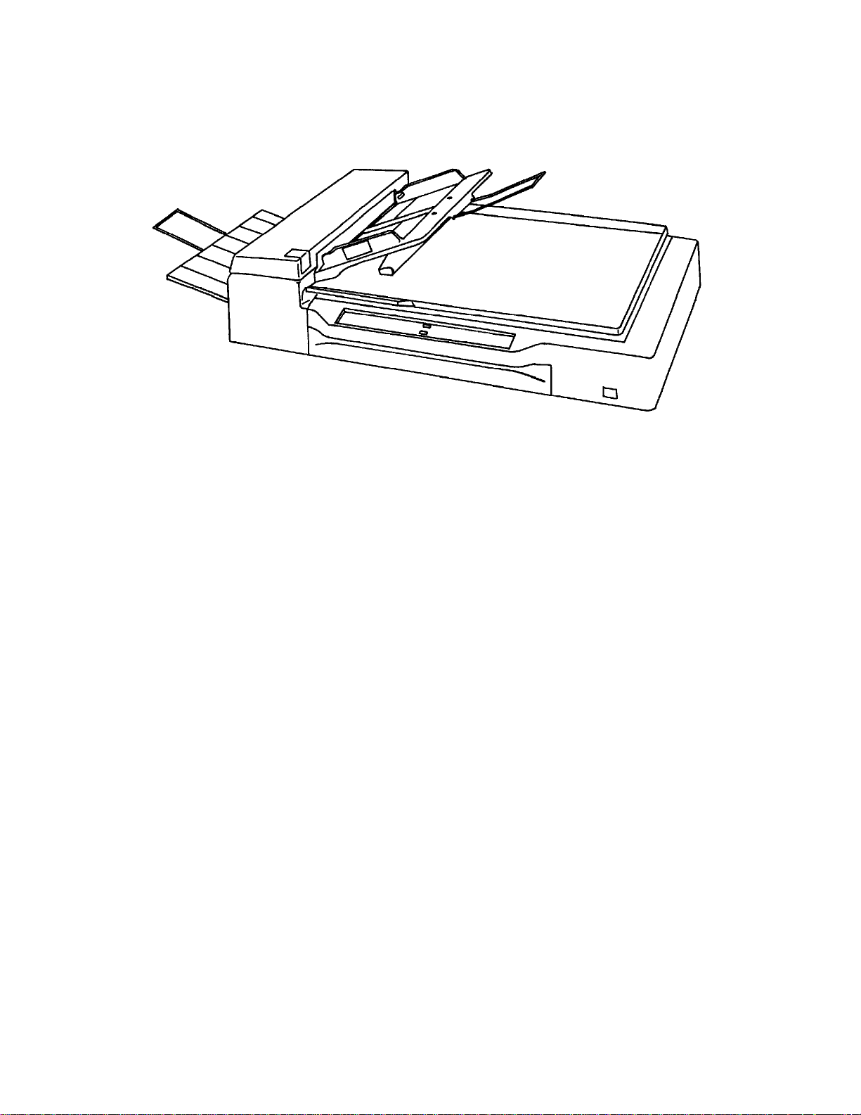
Figure 1.1 M3097G outer view
1 $ 2
Page 12

1.2 Features
(1) Fast reading
This scanner can read data about twice as fast as the M3096G.
For flatbed reading: 1.3 seconds (A4, 200 dpi) (M3096G: 2.3 seconds)
For ADF reading: 36 pages per minute (A4, 200 dpi) (M3096G: 18 pages per
minute)
(2) Large
>capacity document feeder
Up to 100 pages (A4, 55>kg continuous forms) can be loaded into the document
feeder. (M3096G: Up to 50 pages)
(3) High
>quality image
This scanner uses a compact optical system that provides sharper focus.
Furthermore, the use of new LSI chips produces finer images.
(4) New image processing
The standard version of this scanner has error diffusion function. Dithering or error
diffusion can be applied to those areas judged to be photographs by automatic
separation (image processing ¬ option).
(5) Compact
This scanner is small and light. (Its size is almost the same as that of the M3096G)
1 $ 3
Page 13
1.3 Part Names and Functions
aaaaaaaaaaaaaaaaaaaaa
a
a
a
a
aaaaaaaaaaaaaaaaaaaaaaaaaaa
a
a
a
a
a
a
a
a
a
a
a
aaaaaaaaaaaaaaaaa
a
a
a
a
a
a
a
a
a
a
a
aaaaaaaaaaaaaaa
a
a
a
a
a
a
a
a
a
a
a
a
aaaaaaaaaaaaaaaaa
a
a
a
a
aaaaaaaaaaaaaaaaaaaaa
a
a
a
a
aaaaaaaaaaa
a
a
a
a
a
aaaaaaaaaaaaa
a
a
a
a
a
aaaaaaaaaaaaa
a
a
a
a
a
a
aaaaaaaaaaaaaaaaaaaaaaa
aaaaaaaaaaaaaaaaaaaaaaa
aaaaaaaaaaaaaaaaaaaaaaa
aaaaaaaaaaaaaaa
aaaaaaaaaaaaaaa
aaaaaaaaaaaaaaa
aaaaaaaaaaaaaaaaaaa
a
a
a
a
a
aaaaaaaaaaaaaaaaaaaaaaaaa
a
a
a
a
a
This section shows the exterior view of image scanner. This section also provides
names of each part and describes their functions.
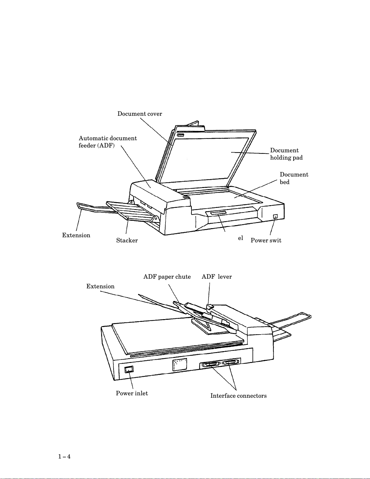
1.3.1 Exterior view of image scanner
The image scanner can read a document of A3 or double>letter size at maximum.
aaaaaaaaaaaaaaaaaaa
aaaaaaaaaaaaaaaaaaa
Document cover
aaaaaaaaaaaaaaaaaaaaaaaaa
Automatic document
aaaaaaaaaaaaaaaaaaaaaaaaa
aaaaaaaaaaaaaaaaaaaaaaaaa
aaaaaaaaaaaaaaaaaaaaaaaaa
feeder (ADF)
aaaaaaaaaaaaaaaaaaaaaaaaa
aaaaaaaaaaa
Extension
aaaaaaaaaaa
a
a
aaaaaaaaaaa
aaaaaaaaaaa
Extension
aaaaaaaaaaa
aaaaaaaaa
Stacker
aaaaaaaaa
a
a
a
a
a
a
a
ADF paper chute
aaaaaaaaaaaaaaaaaaa
Operator panel
aaaaaaaaaaaaaaaaaaa
ADF lever
aaaaaaaaaaaaaaa
Document
aaaaaaaaaaaaaaa
aaaaaaaaaaaaaaa
aaaaaaaaaaaaaaa
holding pad
aaaaaaaaaaaaaaa
aaaaaaaaaaaaa
aaaaaaaaaaaaa
Document
aaaaaaaaaaaaa
aaaaaaaaaaaaa
aaaaaaaaaaaaa
bed
aaaaaaaaaaaaa
aaaaaaaaaaaaaaa
Power switch
aaaaaaaaaaaaaaa
a
a
a
a
a
1 $ 4
aaaaaaaaaaaaaaaaa
Power inlet
aaaaaaaaaaaaaaaaa
Figure 1.2 M3097G part names
a
a
aaaaaaaaaaaaaaaaaaaaaaa
Interface connectors
aaaaaaaaaaaaaaaaaaaaaaa
a
a
Page 14

1.3.2 Functions of each part
Document cover: Closed over and holds a document to be read.
Document bed: A document to be read is placed on the bed also
Document holding pad: Presses a document to the document bed.
Automatic document feeder (ADF):
Stacker: Stacks the read documents.
Extension: Keeps the stacked documents from overhanging.
Power switch: Turns the power on or off.
called Flatbed (FB).
Automatically feeds documents to the reading
position.
Operator panel: Used to control image scanner operations. See the
next section for details of the functions.
ADF paper chute: Holds the documents to be fed by the automatic
document feeder.
ADF lever: Opens or closes the automatic document feeder to
remove documents jammed in the feeder.
Power inlet: To be connected to an AC power outlet with the
power cable.
Interface connectors: To be connected to the host system with interface
cables.
1 $ 5
Page 15

This page is intentionally left blank.
1 $ 6
Page 16

CHAPTER 2 SPECIFICATIONS
2.1 Function Specifications
2.2 Physical Specifications
2.3 Optional Circuit Feature
2.1 Function Specifications
Table 2.1 Function specifications (1/2)
Item
No. Specification
Technology
1
23Operating method
Document size
Light source
4 Green fluorescent lamp
5 ADF capacity MAX 100 (55 kg/continuous forms, A4 paper)
Resolution
6 Horizontal scanning 400 dpi
Gray scale
7
Interface
8
Scanning speed
9 A4/200 dpi: 1.3 s
Output resolution Standard10
CCD image sensor
Flatbed+ ADF (automatic document feeder)
Flatbed
ADF
Vertical scanning 400, 300, 240, 200 dpi
256 steps
SCSI>II
A3/400 dpi: 3.7 s
If the image
processing ¬
option is
installed
MAX 297 ¥ 432 mm
MAX 297 ¥ 432 mm
MIN 105 ¥ 148 mm
400, 300, 240, 200 dpi
(For horizontal scanning and vertical
scanning)
50 dpi to 1600 dpi
(Horizontal scanning and vertical
scanning are independent.)
2 $ 1
Page 17

Table 2.1 Functional specifications (2/2)
No. Item Specification
11
Binarization and
Standard
halftone function
Fixed binarization (Line art)
Dither (Halftone)
Error diffusion (Halftone)
12
Compression
13
Image memory
Image
processing II
option
installed
Standard
CMP II option
installed
Standard
CMP II option
installed
Automatic separation
Image emphasis
Outline extraction
Mirror image
Reverse image
Simplified dynamic threshold
Dynamic threshold
Smoothing
Filtering
Noise removing
Non
MH, MR, or MMR
Non
4 MB
2 $ 2
Page 18

2.2 Physical Specifications
Table 2.2 Physical specifications
ItemNo.
Dimensions
1
(mm)
Weight (kg)
2 25
Power
3
requirements
Power consumption (VA) 150 or less
4
5 Surge current (A) 30 or less
6 Momentary power failure 100% 0.5 Hz
7 Leakage current (mA) 1 or less
8 Dielectric strength AC 1 KV or more for one minute or more
AC line noise9 Voltage 1.2 KV pulse duration 5 os
Height
Width
Depth
Voltage (VAC) 100 to 120, 220 to 240 VAC ±10%
Frequency 50/60 Hz +2% -4%
Specification
173
696
497
SinglePhase
(between FG and AG lines)
Temperature
10
(∞C)
Relative
11 Operating 20 to 80 (no condensation)
humidity (%)
Vibration (G)
12
Indication (%) Operating 5
13
ESD (KV) 8 or more14
Acoustic
15
noise (dBA)
Operating 5 to 35
Nonoperating -20 to +60
Nonoperating 8 to 95 (no condensation)
Operating 0.2
Nonoperating 0.4
Nonoperating 10
Operating 53 or less (ISO DIS 9296)
Nonoperating 40 or less (ISO DIS 9296)
2 $ 3
Page 19

2.3 Optional Circuit Feature
The following option is provided for this scanner:
f Image processing circuit ¬ (M3097E0191)
For the details, refer to Subsection 2.3.1.
f CMP II (M3097G0196)
2.3.1 Image processing circuit ¬ (IPC ¬)
This option has the dynamic threshold function and image processing function.
2.3.1.1 Dynamic threshold function
The main purpose of this function is to read handwritten characters.
Handwritten character recognition preprocessing invalues specifying required
values for threshold curve setting, smoothing mode, and filtering mode.
Noise removal reduces noise often found in images after dynamic threshold
processing.
Threshold curve setting, smoothing mode, filtering mode, and noise removal are all
dynamic threshold circuit (DTC) functions.
(1) Threshold curve setting
The contrast level of the dynamic threshold circuit can be changed with setting 3
bits (8 levels).
(2) Smoothing mode
The convex portion of the segment is removed and the concave portion is filled up to
smooth the segment.
(3) Filtering mode
(a) Ball>point pen mode
This mode is used when this scanner is used as the input device of OCR system.
When using writing materials caused inter>ommission, e.g. ball>point pen, the
density of the omission portion is increased according to the density of
surrounding portion to get the picture does not have inter>omission.
(b) Normal mode
This mode is used when using writing materials other than above.
(4) Noise removal
Among black>dots in the binary picture code, the black>dot for the noise is changed
to white>dot.
2 $ 4
Page 20

2.3.1.2 Image processing function
Table 2.3 Image processing function
No. Function name Details function
1 Automatic separation
Line>drawing/Photo
( )
automatic separation
Recognizes the photo area and Line>drawing
area in one scanning automatically, and outputs
data with applying dither processing or error
diffusion for the photo and the binarizing for the
line>drawing.
2 Outline extraction Extracts the outline of the Line>drawing such as
a thick character.
3 Image emphasis Emphasizes the black>white contrast to raise the
contrast.
4 Overlay (*1) Overlays the pattern on the scanned data and
make the overlayed black data to white data.
5 Reverse image
(White/black conversion)
Converts white into black and black into white
of read data (binary data).
6 Mirror image Turns over the both sides of read data.
7 Simplified dynamic
threshold
Changes the slice level of the binarizing
according to the density of the document.
8 Zooming Magnifies or reduces the image data in the range
between 25% and 400% with 1% step.
9 Subwindow 4 Subwindow can be specified on Main window.
The functions above are all image processing circuit (IPC) functions.
*1 M3097G does not support overlay function.
2 $ 5
Page 21

This page is intentionally left blank.
2 $ 6
Page 22

CHAPTER 3 CONFIGURATION
3.1 Outer Dimensions
3.2 Circuit Configuration
3.3 Operator Panel
3.1 Outer Dimensions
Figure 3.1 shows the outer dimensions of M3097G.
3 $ 1
Page 23
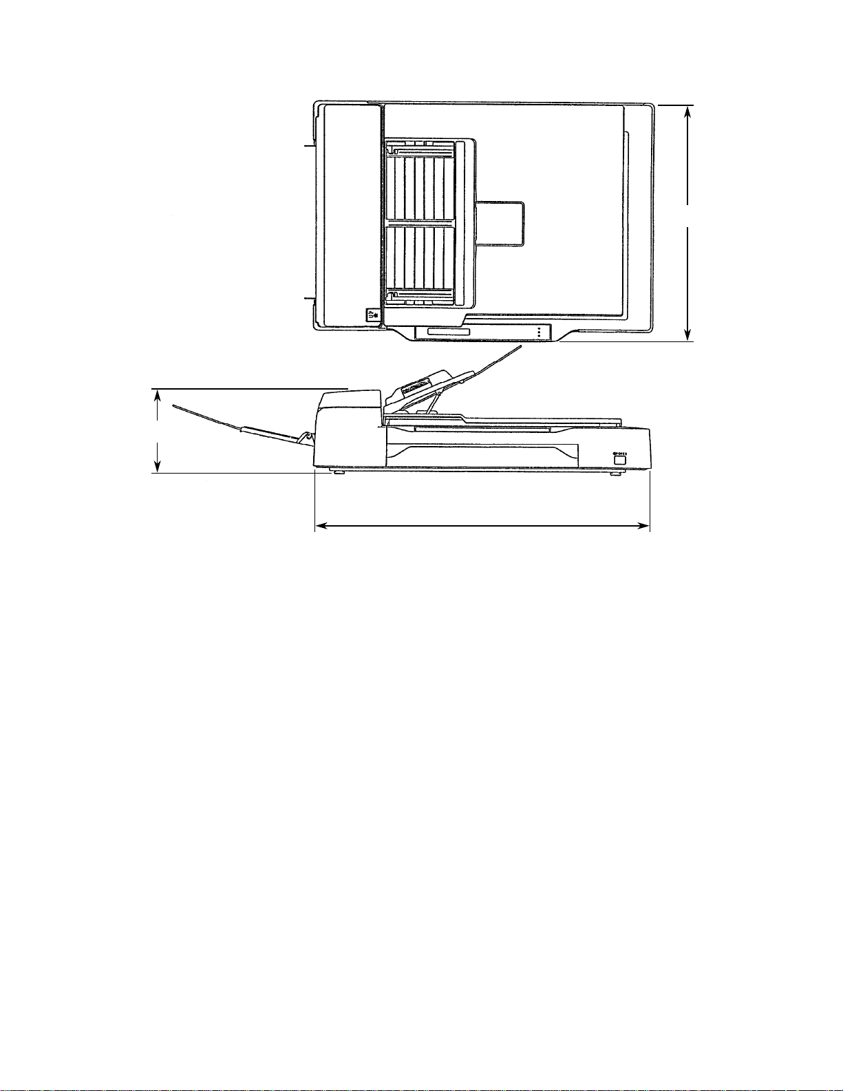
173
Unit: mm
497
696
Figure 3.1 Outer dimensions of M3097G
3 $ 2
Page 24

3.2 Circuit Configuration
This scanner uses CCD image sensor scanning system. This scanner consists of
following sections;
f Optical system (including fluorescent lamp, lenses, and CCD sensor)
f Video circuit (including amplifier and A/D converter)
f Scanner driver (including stepping motor and motor driver circuit)
f Control circuit (MPU circuit)
f Power section
Figure 3.2 is the function block diagram of this scanner.
Controller
100 to 120 VAC
220 to 240 VAC
Control circuit
(MPU circuit)
CMPII
Power section
Power switch
(option)
Motor driver
circuit
Operator panel
Figure 3.2 Function block diagram
Video circuit
Image processing
circuit ¬ (option
Mechanism
section
Flatbed ADF
)
3 $ 3
Page 25
3.3 Operator panel
aaaaaaaaa
a
a
a
a
a
a
a
a
a
aaaaaaaaa
a
a
a
a
a
a
a
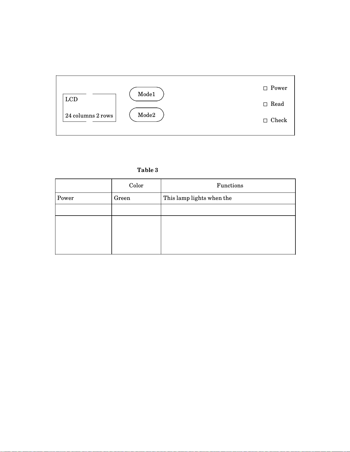
Figure 3.3 shows the operator panel and Table 3.1 shows lamp functions.
" Power
LCD
aaaaaaa
aaaaaaa
aaaaaaa
Mode1
aaaaaaa
a
a
a
a
" Read
aaaaaaa
a
aaaaaaa
24 columns 2 rows
Mode2
aaaaaaa
a
a
" Check
Figure 3.3 M3097G operator panel
Table 3.1 Lamp functions
Lamp name Color Functions
Power Green This lamp lights when the power is on.
Read Green This lamp lights during reading.
Check Yellow This lamp lights when an unrecoverable error
occurs.
This lamp brinks when a paper jam occurs in ADF.
After jammed paper is removed and ADF cover is
closed, this lamp goes off.
3 $ 4
Page 26

CHAPTER 4 INTERFACE
4.1 Physical Specifications
4.2 SCSI Bus
4.3 Bus Phases
4.4 Commands
4.5 Status
4.6 Messages
4.7 Command Sequence
4.8 Status Transition of Logical Unit
4.9 Error Table
4.10 Items for Specifying Window and Subwindows
This image scanner and the host are connected via an 8>bit parallel interface. The interface
follows the ANSI (American National Standards Institute) SCSI 2 (Small Computer System
Interface 2) Revision 10c.
This chapter provides an overview of SCSI (minimum information necessary for
understanding this scanner), as well as descriptions peculiar to the scanner. For details of
SCSI, refer to the ANSI standard.
The following terms are needed to understand this section.
f SCSI device: A host adapter or a target controller that can be attached to the SCSI
bus
f Initiator: An SCSI device (usually a host system) that requests an I/O process to be
performed by another SCSI device (a target)
f Target: An SCSI device that performs an operation requested by an initiator
f Logical unit: A physical or virtual peripheral device that is addressable through a
target
Range of support
(1) System configuration
This scanner operates under the multiinitiator, multitarget environment. An
initiator function is not provided. This scanner incorporates an integrated target
and logical unit (image scanner).
4 $ 1
Page 27

SCSI ID: 0 to 7, variable by EEPROM: default is 5.
Logical unit number (LUN): 000, fixed
(2) Bus phases
All phases are supported.
(3) Commands
The following commands are supported by this scanner:
f INQUIRY
f OBJECT POSITION
f MODE SELECT
f MODE SENSE
f READ
f RELEASE UNIT
f REQUEST SENSE
f RESERVE UNIT
f SEND
f SEND DIAGNOSTIC
f SET SUBWINDOW
f SET WINDOW
f TEST UNIT READY
A control byte is not supported. If the value other than X©00π is specified, an error
is generated.
(4) Statuses
The following statuses are supported by this scanner:
f BUSY
f CHECK CONDITION
f GOOD
f RESERVATION CONFLICT
4 $ 2
Page 28

(5) Messages
The following messages are supported by this scanner:
f ABORT
f BUS DEVICE RESET
f COMMAND COMPLETE
f DISCONNECT
f IDENTIFY
f INITIATOR DETECTED ERROR
f MESSAGE PARITY ERROR
f MESSAGE REJECT
f NO OPERATION
f RESTORE POINTERS
f SAVE DATA POINTER
(6) Others
The bits and fields for which the word ™Reserved∫ is described are checked. For a
non>zero, an error is returned.
4.1 Physical Specifications
The devices linked to this interface are daisy>chained with each other. A
terminator is attached to the ends of the interface. Interface specifications are
shown below.
(1) Connection
SCSI device SCSI device SCSI device
Terminator
Note:
Use shielded interface cable to avoid unintentional errors.
Terminator
4 $ 3
Page 29
(2) Physical specifications
Table 4.1 SCSI physical specifications
Item Specification
Driver/Receiver
Connector
Cable Max. cable length
Characteristic
impedance
Cable type
Stub wire
Signal
Terminator
level
Driver/receiver
Output
characteristics
Input
characteristics
Single>ended
50 Contact Shielded Low Density
6 m
132 ]
25 signal twisted pair
e 0. 1 mm (from main cable in scanner to internal
wiring)
See the figure under (3).
Open collector or three> state driver
Low level (true) = 0. 0 to 0. 5 VDC
High level (false) = 2. 5 to 5. 25 VDC
Output current = 48 mA (corresponding output
voltage e 0. 5 V)
Low level (true) = 0. 0 to 0. 8 VDC
High level (false) = 2. 0 to 5. 25 VDC
Input load = -0. 4 mA max. (at 0. 4 V input voltage)
Input hysteresis = 0. 2 VDC min.
Connector pin assignments
for signal lines
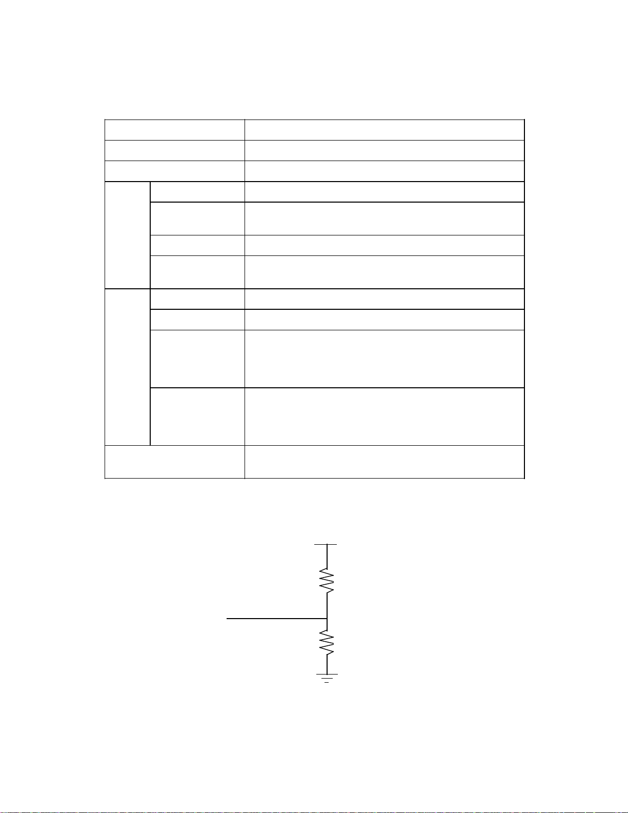
(3) Termination
See (4).
+5 V
220 ]
-signal
330 ]
4 $ 4
Page 30

(4) Pin assignments
Signal name Pin number Signal name
GND 1 26 -DB (0)
GND 2 27 -DB (1)
GND 3 28 -DB (2)
GND 4 29 -DB (3)
GND 5 30 -DB (4)
GND 6 31 -DB (5)
GND 7 32 -DB (6)
GND 8 33 -DB (7)
GND 9 34 -DB (P)
GND 10 35 GND
GND 11 36 GND
Reserved 12 37 Reserved
(Open) 13 38 TERMPWR
Reserved 14 39 Reserved
GND 15 40 GND
GND 16 41 -ATN
GND 17 42 GND
GND 18 43 -BSY
GND 19 44 -ACK
GND 20 45 -RST
GND 21 46 -MSG
GND 22 47 -SEL
GND 23 48 -C/ D
GND 24 49 -REQ
GND 25 50 -I/ O
Note:
Reserved pins are connected to GND.
Figure 4.1 Pin assignment
4 $ 5
Page 31

4.2 SCSI Bus
4.2.1 System configuration
(1) System configuration
The SCSI bus connects up to eight SCSI devices, each linked with a daisy chain. The
both ends of the daisy chain require a terminator.
Each SCSI device operates as an initiator or a target, so that a series of operations
are performed between a pair of initiator and target pair.
The system may be configured with any combination of initiators and targets as
long as the number of the initiators and targets combined does not exceed eight.
(2) Addresses of SCSI devices
Every SCSI device on the bus is assigned a unique address (SCSI ID) that
corresponds to the data bus bit number. ID#7 through ID#0 correspond to DB7
through DB0. The SCSI ID provides identification for specifying particular SCSI
device when an initiator selects a target or when a target reconnects an initiator.
SCSI ID also represents the priority for using the bus in the arbitration phase. (A
description regarding the bus phase is given later.) Priorities are given in the
descending order of data bus bit numbers (DBn), with the highest priority placed on
ID#7 (DB7) and the lowest priority on ID#0 (DB0).
(3) Peripheral equipment
With the basic specification, an initiator can designate up to eight peripheral
devices (logical units) belonging to a single target, where the peripheral devices are
used as the I/O units of the initiator. Logical units are identified and selected by
specifying their LUNs (logical unit numbers) in the IDENTIFY message or
command (CDB: command descriptor block).
This scanner is equipped with a target and a logical unit, and its LUN is 000.
4 $ 6
Page 32

4.2.2 Bus signals
Signal name Type of signal
Initiator
Target
Data DB0
DB1
DB2
DB3
DB4
DB5
DB6
DB7
(Data Bus n)
DBP
(Data Bus
Parity)
Control
signals
BSY
(Busy)
SEL
(Select)
RST
(Reset)
C/ D
(Control/Data)
I/ O
(Input/Output)
MSG
(Message)
Eight data>bit signals, plus a parity>bit signal
that form a DATA BUS. DB(7) is the most
significant bit and has the highest priority during
the ARBITRATION phase. Bit number,
significance, and priority decrease downward to
DB(0).
A data bit is defined as one when the signal value
is true. A data bit is defined as zero when the
signal value is false. Data parity DB(P) shall be
odd. Parity is undefined during the
ARBITRATION phase.
An ™ORtied∫ signal that indicates that the bus is
being used
An ™ORtied∫ signal used either by an initiator to
select a target or by a target to reselect an
initiator
An ™ORtied∫ signal that indicates the RESET
condition
The C/D, I/O, and MSG signals are used to
distinguish between the different information
transfer phases.
REQ
(Request)
ACK
(Acknowledge)
ATN
(Attention)
During an information transfer phase, the target
uses this signal to request the initiator to transfer
data
A signal driven by an initiator to indicate an
acknowledgement for REQ/ACK data transfer
handshake
A signal driven by an initiator to indicate the
ATTENTION condition
4 $ 7
Page 33

4.2.3 Bus signal drive conditions
SCSI devices drive signals of the SCSI bus. The types of SCSI devices are
summarized in the following table, showing the signals that they can drive for each
operating phase of the interface.
There are two kinds of signal driving methods, OR tied and NON>OR tied, as shown
in Table 4.2. During an interface operating sequence, the BSY signal could be
driven simultaneously by two or more SCSI units when the data bus is in the
ARBITRATION or RESELECTION phase. This situation also occurs with the RST
signal (Reset). These two signals must be ORtied. For the other signals, either of
the two methods may be used; further more, different drive methods may coexist for
a signal on the bus.
Table 4.2 Bus phases vs. signal drive sources (1/2)
!!!! Signal
Bus phase
BSY SEL I/ O C/ D
MSG
REQ ACK DB7 to 0
DBP
ATN RST
BUS FREE N N N N N N N N A
ARBITRATION A W N N N N ID N A
SELECTION I&T I N N N I I I A
RESELECTION I&T T T T T I T I A
COMMAND T N T T T I I I A
DATA IN T N T T T I T I A
DATA OUT T N T T T I I I A
STATUS T N T T T I T I A
MESSAGE IN T N T T T I T I A
MESSAGE OUT T N T T T I I I A
4 $ 8
N: The signal shall be released, since it is not being driven by any SCSI device.
A: The signal shall be driven by all SCSI devices that are actively arbitrating.
I: If driven, this signal shall be driven only the active initiator.
T: If the signal is driven, it shall be driven only by the active target.
W: The signal shall be driven by the one SCSI device that wins arbitration.
Page 34

Table 4.2 Bus phases vs. signal drive sources (2/2)
ID: A unique data bit (the SCSI ID) shall be driven by each SCSI device that is
actively arbitrating. The other seven data bits shall be released (shall not
driven) by this SCSI device. The parity bit (DB(P)) may be released or
driven to the true state, but shall never be driven to the false state during
this phase.
I&T: The initiator and target drive the signal according to the interface operating
sequence. The RESELECTION phase includes a sequence in which the
initiator and target simultaneously drive the signal.
The signal shall be driven by the initiator, target, or both, as specified in the
SELECTION phase and RESELECTION phase.
Table 4.3 Method of driving the interface signal
OR connection
False
No signal is driven by any SCSI
device. Signal status is made false by
the termination resistor circuits.
True A SCSI device drives the signal true.
4.3 Bus Phases
The SCSI architecture includes the following eight distinct phases:
f BUS FREE phase
f ARBITRATION phase
f SELECTION phase
f RESELECTION phase
f COMMAND phase
f DATA phase
f STATUS phase
f MESSAGE phase
The SCSI bus can never be in more than one phase at any given time.
NON>OR connection
The signal is driven false by a certain
SCSI device (initiator or target), or is
not driven by any SCSI device.
INFORMATION TRANSFER phase
The following diagram shows how each phase transits to another.
4 $ 9
Page 35

Reset
MESSAGE OUT
SELECTION
COMMAND
BUS FREE
ARBITRATION
DATA OUT
STATUS
RESELECTION
MESSAGE IN
Figure 4.2 Phase sequence
The signal delay times for each bus phase are defined as follows:
Table 4.4 Signal delay times definition (1/3)
No. Item Time Definition
DATA IN or
1 Arbitration
delay
2.4 os The minimum time an SCSI device shall wait from
asserting BSY for arbitration until the DATA BUS can
be examined to see if arbitration has been won. There is
no maximum time.
2 Assertion
period
3 Bus Clear
delay
4 $ 10
90 ns The minimum time that a target shall assert REQ (or
REQB) while using synchronous data transfers. Also,
the minimum time that an initiator shall assert ACK
while using synchronous data transfers.
800 ns The maximum time for an SCSI device to stop driving all
bus signals after:
(1) The BUS FREE phase is detected (BSY and SEL both
false for a bus settle delay)
(2) SEL is received from another SCSI device during the
ARBITRATION phase
(3) The transition of RST to true.
For the first condition listed, the maximum time for an
SCSI device to clear the bus is 1200 nanoseconds from
BSY and SEL first becoming both false. If an SCSI
device requires more than a bus settle delay to detect
BUS FREE phase, it shall clear the bus within a bus
clear delay minus the excess time.
Page 36

Table 4.4 Signal delay times definition (2/3)
No. Item Time Definition
4 Bus free delay 800 ns The minimum time that an SCSI device shall wait from
its detection of the BUS FREE phase (BSY and SEL both
false for a bus settle delay) until its assertion of BSY
when going to the ARBITRATION phase
5 Bus set delay 1.8 os The maximum time for an SCSI device to assert BSY and
its SCSI ID bit on the DATA BUS after it detects BUS
FREE phase (BSY and SEL both false for a bus settle
delay) for the purpose of entering the ARBITRATION
phase
6 Bus settle
delay
7 Cable skew
delay
8 Data release
delay
9 Deskew delay 45 ns The minimum time required for deskew of certain
10 Disconnection
delay
11 Hold time 45 ns The minimum time added between the assertion of REQ
400 ns The minimum time to wait for the bus to settle after
changing certain control signals as called out in the
protocol definitions
10 ns The maximum difference in propagation time allowed
between any two SCSI bus signals measured between
any two SCSI devices
400 ns The maximum time for an initiator to release the DATA
BUS signals following the transition of the I/O signal
from false to true
signals
200 os The minimum time that a target shall wait after
releasing BSY before participating in an ARBITRATION
phase when honoring a DISCONNECT message from the
initiator
(or REQB) or ACK (or ACKB) and the changing of the
data lines to provide hold time in the initiator or target
while using synchronous data transfers. REQB and
ACKB timings only apply to optional wide data
transfers.
12 Negation
period
13 Power>on to
selection time
90 ns The minimum time that a target shall negate REQ (or
REQB) while using synchronous data transfers. Also,
the minimum time that an initiator shall negate ACK (or
ACKB) while using synchronous data transfers. REQB
and ACKB timings only apply to optional wide data
transfers.
10 sec
(recom>
mended)
The recommended maximum time from power
application until an SCSI target is able to respond with
appropriate status and sense data to the TEST UNIT
READY, INQUIRY, and REQUEST SENSE commands
4 $ 11
Page 37

Table 4.4Signal delay times definition (3/3)
No. Item Time Definition
14 Reset to
selection
time
15 Reset hold
time
16 Selection
abort time
17 Selection
timeout
delay
18 Transfer
period
4.3.1 BUS FREE phase
The BUS FREE phase is used to indicate that no SCSI device is actively using the
SCSI bus, and that it is available.
250 ms
(recommended)
25 µs The minimum time over which RST must be kept asserted
200 µs The maximum time required from the moment when
250 ms
(recommended)
The recommended maximum time after a hard RESET
condition until an SCSI target is able to respond with
appropriate status and sense data to the TEST UNIT
READY, INQUIRY, and REQUEST SENSE commands
selection or deselection of an initiator or target is detected
until BSY is asserted
The minimum time required for an initiator or target in
the selection or deselection phase to wait for a BSY
response before it starts the timeout procedure
The minimum allowable period, during sync data
transfer, between the start of consecutive REQ pulses and
the start of consecutive ACK pulses
BSY
SEL
others
SCSI devices shall detect the BUS FREE phase after the SEL and BSY signals are
both false for at least a bus settle delay.
SCSI devices shall release all SCSI bus signals within a bus clear delay after the
BSY and SEL signals become continuously false for a bus settle delay.
bus clear delaybus settle delay
BUS FREE phase
4 − 12
Page 38

4.3.2 ARBITRATION phase
The ARBITRATION phase allows one SCSI device to gain control of the SCSI bus so
that it can initiate or resume an I/O process. The procedure for an SCSI device to
obtain control of the SCSI bus is as follows:
— The SCSI device shall first wait for the BUS FREE phase to occur.
“ The SCSI device shall wait a minimum of a bus free delay after detection of the
BUS FREE phase (i.e. after the BSY and SEL signals are both false for a bus
settle delay) before driving any signal.
” Following the bus free delay in Step “, the SCSI device may arbitrate for the
SCSI bus by asserting both the BSY signal and its own SCSI ID, however, the
SCSI device shall not arbitrate (i.e. assert the BSY signal and its SCSI ID) if
more than a bus set delay has passed since the BUS FREE phase was last
observed.
‘ After waiting at least an arbitration delay (measured from its assertion) the
SCSI device shall examine the DATA BUS. If a higher priority SCSI ID bit is
true on the DATA BUS (DB(7) is the highest), then the SCSI device has lost the
arbitration and the SCSI device may release its signals and return to Step —. If
no higher priority SCSI ID bit is true on the DATA BUS, then the SCSI device
has won the arbitration and it shall assert the SEL signal. Any SCSI device
other than the winner has lost the arbitration and shall release the BSY signal
and its SCSI ID bit within a bus clear delay after the SEL signal becomes true.
An SCSI device that loses arbitration may return to Step —.
’ The SCSI device that wins arbitration shall wait at least a bus clear delay plus a
bus settle delay after asserting the SEL signal before changing any signals.
4 $ 13
Page 39

bus settle
delay
BSY
ARBITRATION phase
bus free delay
SCSI
ID7
ID3
SEL
DB
BSY
SEL
DB(7)
BSY
SEL
DB (3)
bus set
delay
&
bus free
delay
bus set delay
bus free
delay
&
arbitration delay
bus clear delay
bus clear delay
+ bus settle delay
arbitration delay
BSY
ID1
&
SEL
DB (1)
bus free
delay
ID7: Succeeds in ARBITRATION
ID3: Detects the SEL signal of other SCSI unit
ID1: Detects the SCSI ID with higher priority than itself
&: The point at which the BUS FREE phase is detected by each SCSI unit.
4 $ 14
Page 40

4.3.3 SELECTION phase
The SELECTION phase allows an initiator to select a target for the purpose of
initiating some target function (e.g., READ or WRITE command). During the
SELECTION phase the I/O signal is negated so that this phase can be distinguished
from the RESELECTION phase.
— The SCSI device that won the arbitration has both the BSY and SEL signals
asserted and has delayed at least a bus clear delay plus a bus settle delay before
ending the ARBITRATION phase. The SCSI device that won the arbitration
becomes an initiator by not asserting the I/O signal.
“ The initiator shall set the DATA BUS to a value which is the OR of its SCSI ID
bit and the targetπs SCSI ID bit, and it shall assert the ATN signal.
” The initiator shall then wait at least two deskew delays and release the BSY
signal.
‘ The initiator shall then wait at least a bus settle delay before looking for a
response from the target.
’ The target shall determine that it is selected when the SEL signal and its SCSI
ID bit are true and the BSY and I/O signals are false for at least a bus settle
delay. The selected target may examine the DATA BUS in order to determine
the SCSI ID of the selecting initiator. The selected target shall then assert the
BSY signal within a selection abort time of its most recent detection of being
selected; this assertion is required for correct operation of the selection time>out
procedure.
The target shall not respond to a selection if bad parity is detected. Also, if more
than two SCSI ID bits are on the DATA BUS, the target shall not respond to
selection.
÷ No less than two deskew delays after the initiator detects the BSY signal is
true, it shall release the SEL signal and may change the DATA BUS. The
target shall wait until the SEL signal is false before asserting the REQ signal to
enter an information transfer phase.
SELECTION phase
bus clear delay
+ bus settle delay
I/O
BSY
SEL
DB
deskew
delay ¥ 2
deskew
delay ¥ 2
4 $ 15
Page 41

4.3.4 RESELECTION phase
RESELECTION is an optional phase that allows a target to reconnect to an
initiator for the purpose of continuing some operation that was previously started
by the initiator but was suspended by the target (i.e., the target disconnected by
allowing a BUS FREE phase to occur before the operation was complete).
— Upon completing the ARBITRATION phase, the winning SCSI device has both
the BSY and SEL signals asserted and has delayd at least a bus clear delay plus
a bus settle delay. The winning SCSI device becomes a target by asserting the
I/O signal.
“ The winning SCSI device shall also set the DATA BUS to a value that is the
logical OR of its SCSI ID bit and the initiatorπs SCSI ID bit.
” The target shall wait at least two deskew delays and release the BSY signal.
‘ The target shall then wait at least a bus settle delay before looking for a
response from the initiator.
’ The initiator shall determine that it is reselected when the SEL and I/O signals
and its SCSI ID bit are true and the BSY signal is false for at least a bus settle
delay. The reselected initiator may examine the DATA BUS in order to
determine the SCSI ID of the reselecting target. The reselected initiator shall
then assert the BSY signal within a selection abort time of its most recent
detection of being reselected; this is required for correct operation of the time>
out procedure. The initiator shall not respond to a RESELECTION phase if bad
parity is detected. Also, the initiator shall not respond to a RESELECTION
phase if other than two SCSI ID bits are on the DATA BUS.
÷ After the target detects the BSY signal is true, it shall also assert the BSY
signal and wait at least two deskew delays and then release the SEL signal.
The target may then change the I/O signal and the DATA BUS. After the
reselected initiator detects the SEL signal is false, it shall release the BSY
signal. The target shall continue asserting the BSY signal until it relinguishes
the SCSI bus.
RESELECTION phase
bus clear delay
+ bus settle delay
I/O
BSY
SEL
DB
deskew
delay ¥ 2
TARG INIT
deskew
delay ¥ 2
TARG
INIT
4 $ 16
Page 42

4.3.5 INFORMATION TRANSFER phases
Note:
The COMMAND, DATA, STATUS, and MESSAGE phases are all grouped
together as the information transfer phases because they are all used to transfer
data or control information via the DATA BUS. The actual content of the
information is beyond the scope of this section.
The C/D, I/O, and MSG signals are used to distinguish between the different
information transfer phases (see Table 4.5). The target drives these three signals
and therefore controls all changes from one phase to another. The initiator can
request a MESSAGE OUT phase by asserting the ATN signal, while the target can
cause the BUS FREE phase by releasing the MSG, C/D, I/O, and BSY signals.
Table 4.5 INFORMATION TRANSFER phase type
Phase C/D I/O MSG DB7 to 0, P Transfer direction
DATA OUT 0 0 0 Data INIT TARG
DATA IN 0 1 0 Data INIT TARG
COMMAND 1 0 0 Command INIT TARG
STATUS 1 1 0 Status INIT TARG
* 0 0 1
* 0 1 1
MESSAGE OUT 1 0 1 Message INIT TARG
MESSAGE IN 1 1 1 Message INIT TARG
0: False
1 True
INIT: Initiator
TARG: Target
* : Reserved for future standardization
4 – 17
Page 43

INFORMATION
INFORMATION TRANSFER phase
Min. 0ns bus settle delaybus settle delay
BSY
SEL
C/D,
MSG, I/O
REQ
ACK
DB
TRANSFER phase
The INFORMATION TRANSFER phases use one or more REQ/ACK handshakes to
control the information transfer. Each REQ/ACK handshake allows the transfer of
one byte of information. During the INFORMATION TRANSFER phases the BSY
signal shall remain true and the SEL signal shall remain false. Additionally,
during the INFORMATION TRANSFER phases, the target shall continuously
envelope the REQ/ACK handshake (s) with the C/D, I/O, and MSG signals in such a
manner that these control signals are valid for a bus settle delay before the
assertion of the REQ signal of the first handshake. These control signals remain
valid until after the negation of the ACK signal at the end of the handshake of the
last transfer of the phase.
(1) Asynchronous information transfer
The target shall control the direction of information transfer by means of the I/O
signal. When the I/O signal is true, information shall be transferred from the target
to the initiator. When the I/O signal is false, information shall be transferred from
the initiator to the target.
a. Asynchronous transfer from target to initiator
If the I/O signal is true (transfer to the initiator), the target shall first drive the
DB(7>0, P) signals to their desired values, delay at least one deskew delay plus a
cable skew delay then assert the REQ signal. The DB(7>0, P) signals shall
remain valid until the ACK signal is true at the target. The initiator shall read
the DB(7>0, P) signals after the REQ signal is true then indicate its acceptance
of the data by asserting the ACK signal. When the ACK signal becomes true at
the target, the target may change or release the DB(7>0, P) signals and shall
negate the REQ signal. After the REQ signal is false, the initiator shall then
negate the ACK signal.
4 $ 18
Page 44

After the ACK signal is false, the target may continue the transfer by driving
the DB(7>0, P) signals and asserting the REQ signal, as previously described.
BSY
SEL
C/D, MSG
I/O
REQ
ACK
DB
bus settle delay
deskew delay +
cable skew delay
deskew delay
+ cable skew delay
b. Asynchronous transfer from initiator to target
If the I/O signal is false (transfer to the target), the target shall request
information by asserting the REQ signal. The initiator shall drive the DB(7>0,
P) signals to their desired values, delay at least one deskew delay plus a cable
skew delay then assert the ACK signal. The initiator shall continue to drive the
DB(7>0, P) signals until the REQ signal is false. When the ACK signal becomes
true at the target, the target shall read the DB(7>0, P) signals then negate the
REQ signal. When the REQ signal becomes false at the initiator, the initiator
may change or release the DB(7>0, P) signals and shall negate the ACK signal.
The target may continue the transfer by asserting the REQ signal, as previously
described.
4 $ 19
Page 45

BSY
SEL
C/D, MSG
I/O
REQ
ACK
DB
bus settle
delay
deskew delay +
cable skew delay
deskew delay
+ cable skew delay
4.4 Commands
Commands are directions issued from an initiator to a target. This image scanner
supports the following range of the commands specified by the SCSI standard.
(a) The identification number of logical unit (LUN: logical unit number) is B©000π.
If this scanner receives a value other than 000, it returns error information as
follows:
f Status key: B©00001π (CHECK CONDITION)
f Sense key: X©5π (ILLEGAL REQUEST)
(b) Relative addressing is not supported.
If this scanner receives a relative address (RelAdr) = 1, it returns error
information as follows:
f Status key: B©00001π (CHECK CONDITION)
f Sense key: X©5π (ILLEGAL REQUEST)
(c) A control byte is not supported.
If this scanner receives a control byte b X©00π , it returns error information as
follows:
4 $ 20
f Status key: B©00001π (CHECK CONDITION)
f Sense key: X©5π (ILLEGAL REQUEST)
Page 46

(d) A bit and field described as ™Reserved∫ are 0.
If this scanner receives a value other than 0, it returns error information as
follows:
f Status key: B©00001π (CHECK CONDITION)
f Sense key: X©5π (ILLEGAL REQUEST)
The commands supported by this scanner are listed below.
Table 4.6 Commands
Command
Operation
code (hex)
Description
RESERVE UNIT 16 Declares the exclusive use of a logical unit
RELEASE UNIT 17 Cancels the declaration of the execlusive use of a
logical unit
INQUIRY 12 Examines the information regarding the target and
logical unit
REQUEST SENSE 03 Requests a target for sense data
SEND
1D Requests a target for self>check
DIAGNOSTIC
TEST UNIT
00 Checks whether or not a logical unit is ready
READY
SET WINDOW 24 Sets a window
SET
C0 Sets subwindows
SUBWINDOW
SEND 2A Sends Dither Matrix
OBJECT
31 Controls the automatic document feeder
POSITION
READ 28 Requests transfer of image data
MODE SELECT 15 Selects operating mode of the device.
MODE SENSE 1A Requests operating mode of the device.
4 $ 21
Page 47

4.4.1 RESERVE UNIT command
The following table shows the normal sequence of the RESERVE UNIT command
when used with this scanner.
Step Bus phase Initiator operation ¨ Æ Target operation
1 BUS FREE Verifies bus free
2 ARBITRATION Obtains bus>usage
right
3 SELECTION Selects target Æ
Drives BSY signal
4 MESSAGE OUT Selects logical unit Æ
5 COMMAND Specifies
Æ
RESERVE UNIT
(CDB)
6 STATUS ¨ Reports GOOD status
7 MESSAGE IN ¨ Reports message (Command
Complete)
Releases BSY signal
8 BUS FREE
(1) RESERVE UNIT command: COMMAND phase (initiator Æ target)
Where a logical unit can be accessed by two or more initiators, there could be
interferences with command sequences, data, etc. This situation can be avoided by
issuing the RESERVE UNIT command before initiating a series of operations.
Once a logical unit has properly accepted the RESERVE UNIT command, it will be
occupied by the initiator that issued the RESERVE UNIT command. If the 3rd
party reservation option is supported, the logical unit might be occupied by another
SCSI unit % one having an initiator function % which is specified TPID. In this
condition, called ™reserved,∫ the logical unit cannot be accessed from any other
initiators. The reserved condition remains effective until one of the following
events take place:
4 $ 22
— The reservation is replaced by a new RESERVE COMMAND from the same
initiator that has reserved the logical unit. (Issuing another RESERVE UNIT
command with the reservation still effective does not results in an error. The
previously established reservation is released as a result of “, ” or ‘ described
below.)
“ The RELEASE UNIT command is issued from the same initiator that has
reserved the logical unit.
Page 48

” The BUS DEVICE RESET message is sent from any initiator.
aaaaaaaaaaaaa
a
a
a
a
a
aaaaaaaaaaaaa
a
a
a
a
a
aaaaaaaaaaaaa
a
a
a
a
aaaaaaaaaaaaa
a
a
a
a
a
aaaaaaaaaaaaa
a
a
a
a
aaaaaaaaaaaaa
a
a
a
a
a
aaaaaaaaaaaaa
a
a
a
a
aaaaaaaaaaaaa
a
a
a
a
a
‘ A hardware reset condition is detected.
The condition in effect after ” or ‘ is indicated by a sense key X©6π (UNIT
ATTENTION), which is returned in response to a subsequent command.
When a logical unit is already reserved by another initiator, if a command other
than RELEASE UNIT, INQUIRY, or REQUEST SENSE is issued, the target
returns the following status:
f Status: B©01100π (RESERVATION CONFLICT)
The initiator having reserved a logical unit can change the reservation by
issuing the RESERVE UNIT command to the same logical unit.
The command descriptor block (CDB) of this command is shown in the following
illustration.
Byte 0
aaaaaaaaaaa
aaaaaaaaaaa
1
a
7
aaaaaaaaaaa
a
aaaaaaaaaaa
a
6
aaaaaaaaaaa
5
a
aaaaaaaaaaa
Logical unit number TP TPID
2
3
4
5
a. TP (third party) : Byte 1
As this scanner does not support the 3rd party reservation option, setting
this bit to 1 causes the target to return the following error information:
f Status: B©00001π (CHECK CONDITION)
f Sense key: X©5π (ILLEGAL REQUEST)
b. TPID (third party device ID) : Byte 1
This scanner ignores TPID.
aaaaaaaaaaa
aaaaaaaaaaa
a
4
aaaaaaaaaaa
3
a
aaaaaaaaaaa
Operation code X©16π
(Reserved)
Control byte
aaaaaaaaaaa
2
aaaaaaaaaaa
a
aaaaaaaaaaa
1
a
aaaaaaaaaaa
aaaaaaaaaaa
0
aaaaaaaaaaa
(Reserved)
a
a
4 $ 23
Page 49

4.4.2 RELEASE UNIT command
aaaaaaaaaaaaa
a
a
a
a
a
aaaaaaaaaaaaa
a
a
a
a
a
aaaaaaaaaaaaa
a
a
a
a
aaaaaaaaaaaaa
a
a
a
a
a
aaaaaaaaaaaaa
a
a
a
a
aaaaaaaaaaaaa
a
a
a
a
a
aaaaaaaaaaaaa
a
a
a
a
aaaaaaaaaaaaa
a
a
a
a
a
The following table shows the normal sequence of the RESERVE UNIT command
when used with this scanner.
Step Bus phase Initiator operation ¨ Æ Target operation
1 BUS FREE Verifies bus free
2 ARBITRATION Obtains bus>usage
right
3 SELECTION Selects target Æ
Drives BSY signal
4 MESSAGE OUT Selects logical unit Æ
5 COMMAND Specifies
Æ
RELEASE UNIT
(CDB)
6 STATUS ¨ Reports GOOD status
7 MESSAGE IN ¨ Reports message (Command
Complete)
Releases BSY signal
8 BUS FREE
(1) RELEASE UNIT command: COMMAND phase (initiator Æ target)
The RELEASE UNIT command releases a reserved status. If this command comes
from an initiator that has not declared reservation, the target ignores the command
and responds with the GOOD status (the reserved status is not released).
The CDB of this command is shown in the following illustration.
aaaaaaaaaaa
aaaaaaaaaaa
a
7
aaaaaaaaaaa
a
aaaaaaaaaaa
a
6
aaaaaaaaaaa
5
a
aaaaaaaaaaa
aaaaaaaaaaa
4
aaaaaaaaaaa
a
aaaaaaaaaaa
3
a
aaaaaaaaaaa
aaaaaaaaaaa
2
aaaaaaaaaaa
a
aaaaaaaaaaa
1
a
aaaaaaaaaaa
Byte 0 Operation code X©17π
aaaaaaaaaaa
0
aaaaaaaaaaa
a
a
1
Logical unit number
TP TPID
(Reserved)
2
3
(Reserved)
4
5
Control byte
4 $ 24
Page 50

a. TP (third party) : Byte 1
As this scanner does not support the 3rd party reservation option, setting this
bit to 1 causes the target to return the following error information:
f Status: B©00001π (CHECK CONDITION)
f Sense key: X©5π (ILLEGAL REQUEST)
b. TPID (third party device ID) : Byte 1
This scanner ignores TPID.
4.4.3 INQUIRY command
The following table shows the normal sequence of the INQUIRY command when
used with this scanner.
Step Bus phase Initiator operation ¨ Æ Target operation
1 BUS FREE Verifies bus free
2 ARBITRATION Obtains bus>usage
right
3 SELECTION Selects target Æ
Drives BSY signal
4 MESSAGE OUT Selects logical unit Æ
5 COMMAND Specifies INQUIRY
Æ
(CDB)
6 DATA IN ¨ Reports inquiry data
7 STATUS ¨ Reports GOOD status
8 MESSAGE IN ¨ Reports message (Command
Complete)
Releases BSY signal
9 BUS FREE
(1) INQUIRY command: COMMAND phase (initiator Æ target)
The INQUIRY command used to check information regarding a target and logical
unit.
The CDB of this command is shown in the following illustration.
4 $ 25
Page 51

Byte 0
aaaaaaaaaaaaa
a
a
a
a
a
a
a
aaaaaaaaaaaaa
a
a
a
a
a
a
a
aaaaaaaaaaaaa
a
a
a
a
a
a
aaaaaaaaaaaaa
a
a
a
a
a
a
a
aaaaaaaaaaaaa
a
a
a
a
a
a
aaaaaaaaaaaaa
a
a
a
a
a
a
a
aaaaaaaaaaaaa
a
a
a
a
a
a
aaaaaaaaaaaaa
a
a
a
a
a
a
a
aaaaaaaaaaa
aaaaaaaaaaa
7
aaaaaaaaaaa
a
aaaaaaaaaaa
a
aaaaaaaaaaa
6
a
aaaaaaaaaaa
a
aaaaaaaaaaa
a
aaaaaaaaaaa
5
a
aaaaaaaaaaa
aaaaaaaaaaa
aaaaaaaaaaa
aaaaaaaaaaa
a
aaaaaaaaaaa
a
4
aaaaaaaaaaa
3
a
aaaaaaaaaaa
Operation code X©12π
aaaaaaaaaaa
aaaaaaaaaaa
2
aaaaaaaaaaa
a
aaaaaaaaaaa
a
aaaaaaaaaaa
1
a
aaaaaaaaaaa
aaaaaaaaaaa
aaaaaaaaaaa
0
aaaaaaaaaaa
a
a
a
1
2
3
4
5
Logical unit number
Page code
(Reserved)
Allocation length
Control byte
(Reserved)
a. EVPD (enable vital product data) : Byte 1
This scanner does not support EVPD. If this bit is set to 1, the scanner returns
the following error information:
f Status: B©00001π (CHECK CONDITION)
f Sense key: X©5π (ILLEGAL REQUEST)
b. Page code: Byte 2
This scanner does not support page code. If this bit is set to 1, the scanner
returns the following error information:
f Status: B©00001π (CHECK CONDITION)
f Sense key: X©5π (ILLEGAL REQUEST)
EVPD
c. Allocation length: Byte 4
This field specifies the storage area in bytes that the initiator allocates for
inquiry data. If a 0 is set here, inquiry data is not transferred, but this is not
regarded as an error. The target terminates the DATA IN phase when it has
transferred either the bytes of inquiry data specified in this field or all of
effective inquiry data.
4 $ 26
Page 52

(2) Inquiry data: DATA IN pahse (target Æ initiator)
aaaaaaaaaaaaa
a
a
a
a
a
aaaaaaaaaaaaa
a
a
a
a
a
aaaaaaaaaaaaa
a
a
a
a
aaaaaaaaaaaaa
a
a
a
a
a
aaaaaaaaaaaaa
a
a
a
a
aaaaaaaaaaaaa
a
a
a
a
a
aaaaaaaaaaaaa
a
a
a
a
aaaaaaaaaaaaa
a
a
a
a
a
Byte 0
10
1F
aaaaaaaaaaa
aaaaaaaaaaa
1
2
3
4
5
6
7
8
(MSB)
F
(MSB)
7
RMB
ISO version
AENC
RelAdr
a
aaaaaaaaaaa
a
aaaaaaaaaaa
a
6
aaaaaaaaaaa
5
a
aaaaaaaaaaa
aaaaaaaaaaa
4
aaaaaaaaaaa
a
aaaaaaaaaaa
3
a
aaaaaaaaaaa
aaaaaaaaaaa
2
aaaaaaaaaaa
a
aaaaaaaaaaa
1
a
aaaaaaaaaaa
aaaaaaaaaaa
aaaaaaaaaaa
Peripheral device typePeripheral qualifier
Device type qualifier
ECMA version
(Reserved)
ANSI approved version
Response data format
Additional length (n>4)
(Reserved)
Wbus32 Wbus16 SYNC LINKED CACHE CMDQUE SftRst
Vendor identification
Product identification
0
(LSB)
(LSB)
a
a
20
(MSB)
23
24
5F
a. Peripheral qualifier: Byte 0
Indicates the connection status of the devices under control of the target. This
scanner returns B©000π.
b. Peripheral device type: Byte 0
Indicates the type of the devices under control of the target. This scanner
returns B©00110π (scanner).
Product revision level
(LSB)
(Reserved)
4 $ 27
Page 53

c. Removable medium (RMB) : Byte 1
This scanner does not support RMB. This scanner returns B©0π.
d. Device type qualifier: Byte 1
This scanner does not support this field. This scanner always returns
B©0000000π.
e. ISO version, ECMA version, ANSI approved version: Byte 2
Indicates the version number of the governing standard. This scanner returns
X©02π (SCSI>2).
f. Asynchronous event notification capability (AENC) : Byte 3
This scanner does not support this field, so it returns B©0π.
g. Response data format: Byte 3
Indicates the standard, and its version number, that governs the format of
inquiry data. This scanner returns B©0010π (SCSI>2).
h. Additional length (n>4) : Byte 4
Specifies the number of bytes, from byte 5 to the last byte. This value will not
change with the allocation length value specified in CDB. This scanner returns
X©5Bπ (the 91 bytes from byte 5 to byte 5F).
i. RelAdr, Wbus32, Wbus16: Byte 7
This scanner does not support RelAdr/ Wbus32/ Wbus16. This scanner returns
B©000π.
j. SYNC (synchronous transfer) : Byte 7
This scanner returns B©0π (™synchronous transfer not supported∫ ).
k. Linked, cache, CMDQUE: Byte 7
This scanner does not support linked/cache/CMDQUE. This scanner returns
B©000π.
l. sftRst (Soft Reset) : Byte 7
This scanner performs Hardware Reset. This scanner returns B©0π.
m. Vendor identification: Bytes 8 to F
Indicates the vendor of the logical unit in ASCII code. The vendor name is left>
justified, with the blank filled with spaces (X©20π). This scanner returns
™FUJITSU∫.
4 $ 28
Page 54

n. Product identification: Bytes 10 to 1F
Indicates the product name in ASCII code. The name is left>justified, with the
blank filled with spaces (X©20π). This scanner returns one of the following
names:
M3097G without option
M3097Gi with image processing II option
M3097Gm with CMPII option
M3097Gim with image processing II option and CMP II option
o. Product revision level: Bytes 20 to 23
Indicates the version number of the product in ASCII code. This number is left>
justified, with the blank filled with spaces (X©20π).
4.4.4 REQUEST SENSE command
The following table shows the normal sequence of the REQUEST SENSE command
when used with this scanner.
Step Bus phase Initiator operation ¨ Æ Target operation
1 BUS FREE Verifies bus free
2 ARBITRATION Obtains bus>usage
right
3 SELECTION Selects target Æ
Drives BSY signal
4 MESSAGE OUT Selects logical unit Æ
5 COMMAND Specifies
Æ
REQUEST SENSE
(CDB)
6 DATA IN ¨ Reports sense data
7 STATUS ¨ Reports GOOD status
8 MESSAGE IN ¨ Reports message (Command
Complete)
Releases BSY signal
9 BUS FREE
4 $ 29
Page 55

(1) REQUEST SENSE command: COMMAND phase (initiator Æ target)
aaaaaaaaaaaaa
a
a
a
a
a
a
a
aaaaaaaaaaaaa
a
a
a
a
a
a
a
aaaaaaaaaaaaa
a
a
a
a
a
a
aaaaaaaaaaaaa
a
a
a
a
a
a
a
aaaaaaaaaaaaa
a
a
a
a
a
a
aaaaaaaaaaaaa
a
a
a
a
a
a
a
aaaaaaaaaaaaa
a
a
a
a
a
a
aaaaaaaaaaaaa
a
a
a
a
a
a
a
The REQUEST SENSE command requests the sense data that shows the status of a
logical unit. On receiving this command, the target sets the unitπs status in the
sense data and returns it to the initiator.
The CDB of this command is shown in the following illustration.
Byte 0
aaaaaaaaaaa
aaaaaaaaaaa
aaaaaaaaaaa
1
a
aaaaaaaaaaa
a
7
aaaaaaaaaaa
a
aaaaaaaaaaa
a
a
6
a
Logical unit number
aaaaaaaaaaa
aaaaaaaaaaa
5
aaaaaaaaaaa
aaaaaaaaaaa
aaaaaaaaaaa
aaaaaaaaaaa
a
aaaaaaaaaaa
a
4
aaaaaaaaaaa
3
a
aaaaaaaaaaa
Operation code X©03π
2
(Reserved)
3
4
5
Allocation length
Control byte
a. Allocation length: Byte 4
Specifies the storage area in bytes that the initiator allocates for sense data. If a
0 is set here, sense data is not transferred, but this is not treated as an error.
The target terminates the DATA IN phase when it has transferred either the
bytes of sense data specified in this field or all of effective sense data.
(2) Sense data: DATA IN phase (target Æ initiator)
The target creates sense data if its status is B©00001π (CHECK CONDITION) or if a
BUS FREE error has occurred. This scanner creates sense data when any of the
errors described later is encountered.
aaaaaaaaaaa
aaaaaaaaaaa
2
aaaaaaaaaaa
(Reserved)
a
aaaaaaaaaaa
a
aaaaaaaaaaa
1
a
aaaaaaaaaaa
aaaaaaaaaaa
aaaaaaaaaaa
0
aaaaaaaaaaa
a
a
a
The sense data on this scanner is shown in the following illustration.
4 $ 30
Page 56

Byte 0
aaaaaaaaaaaaa
a
a
a
a
a
aaaaaaaaaaaaa
a
a
a
a
a
aaaaaaaaaaaaa
a
a
a
a
aaaaaaaaaaaaa
a
a
a
a
a
aaaaaaaaaaaaa
a
a
a
a
aaaaaaaaaaaaa
a
a
a
a
a
aaaaaaaaaaaaa
a
a
a
a
aaaaaaaaaaaaa
a
a
a
a
a
aaaaaaaaaaa
aaaaaaaaaaa
7
Valid
a
aaaaaaaaaaa
a
aaaaaaaaaaa
6
a
aaaaaaaaaaa
a
aaaaaaaaaaa
5
aaaaaaaaaaa
aaaaaaaaaaa
4
a
aaaaaaaaaaa
a
aaaaaaaaaaa
3
Error code
aaaaaaaaaaa
aaaaaaaaaaa
2
a
aaaaaaaaaaa
a
aaaaaaaaaaa
1
aaaaaaaaaaa
aaaaaaaaaaa
0
a
a
1
2
3
(MSB)
6
7
8 (MSB)
B
C
D
E
F
SKSV
10
11
FM
EOM ILI
Command>specific information byte
Segment number
(Reserved)
Information bytes
Additional sense length
Additional sense code
Additional sense code qualifier
Field replaceable unit code
Sense>key specific bytes
Sense key
(LSB)
(LSB)
a. Valid: Byte 0
Indicates whether or not the INFORMATION BYTES field is as specified by
ANSI. This scanner returns B©1π (™specified by ANSI∫ ).
b. Error code: Byte 0
Differentiates between current error or deferred error. This scanner returns
X©70π (™CURRENT ERROR∫ ).
c. Segment number: Byte 1
This scanner does not support SEGMENT NUMBER. This scanner returns
X©00π.
d. FM (file mark) : Byte 2
This scanner does not support FM. This scanner returns B©0π.
e. EOM (end of medium) : Byte 2
Indicates the completion of window reading: 1 when completed, 0 when not
completed
4 $ 31
Page 57

f. ILI (incorrect length indicator) : Byte 2
Indicates that an error in logical block length has been detected
g. Sense key: Byte 2
Indicates the logical unit status using a sense key. This scanner supports the
sense keys shown in the following table:
Sense key Status of logical unit
!!0 NO SENSE
The logical unit has no information to be specifically described in a
sense key. This status occurs because either a command has succeeded,
or because a command has terminated in the CHECK CONDITION
status since the ILI bit has been set to 1.
!!2 NOT READY
The specified logical unit cannot be accessed.
!!3 MEIDUM ERROR
A command has terminated because of a trouble with the medium.
Typical causes of this error with this scanner are that the ADF paper
chute is empty, paper is jammed in the ADF, or the ADF cover has been
opened.
!!4 HARDWARE ERROR
An unrecoverable error was detected.
!!5 ILLEGAL REQUEST
An illegal parameter exists either in a command (CDB), or in a group of
parameters sent in the DATA OUT phase following a command.
!!6 UNIT ATTENTION
The target has been reset.
!!B ABORTED COMMAND
The target has aborted a command.
h. Information bytes: Bytes 3 to 6
The information in this field is effective if ILI is 1. This scanner returns the
remainder (2πs complement for any negative value) so the requested transfer
amount subtracted by the actual transfer amount.
i. Additional sense length: Byte 7
Specifies the number of sense bytes that follows. Even if all additional sense
bytes cannot be tranferred because the allocation length in CDB is small, the
value in this field is not adjusted to indicate the remaining data. This scanner
always assumes X©0Aπ.
4 $ 32
Page 58

j. Command>specific information bytes: Bytes 8 to B
On this scanner, this field is not supported and is fixed to X©00000000π.
k. Additional sense code, additional sense code qualifier: Bytes C and D
A combination of these fields specifies detailed information about the error
reported in the sense key. This scanner reports the following information:
Sense
key
Additional
sense code
Additional
sense code
qualifier
Description
0 00 00 No> sense
2 00 00 Not ready
2 80 01 Interlock switch is opened
3 80 01 Jam
3 80 02 ADF cover open
3 80 03 Document chuter empty of paper
3 80 04 Detects job separation sheet
(See Appendix A.5)
4 80 01 Blown fuse for FB motor
4 80 02 Blown fuse for heater
4 80 03 Blown lamp fuse
4 80 04 Blown fuse for ADF motor
4 80 05 Mechanical alarm
4 80 06 Optical alarm
4 44 00 Abnormal internal target
4 47 00 SCSI parity error
5 20 00 Invalid command
5 24 00 Invalid field in CDB
5 25 00 Unsupported logical unit
5 26 00 Invalid field in parameter list
5 2C 02 Wrong window combination
6 00 00 UNIT ATTENTION
B 43 00 Message error
B 80 01 Image transfer error
4 $ 33
Page 59

l. Sense>key specific bytes: Bytes F to 11
This field is reserved on this scanner.
(X©00000000π must not be expected.)
4.4.5 SEND DIAGNOSTIC command
The following table shows the normal sequence of the SEND DIAGNOSTIC
command when used with this scanner.
Step Bus phase Initiator operation ¨ Æ Target operation
1 BUS FREE Verifies bus free
2 ARBITRATION Obtains bus>usage
right
3 SELECTION Selects target Æ
Drives BSY signal
4 MESSAGE OUT Selects logical unit Æ
5 COMMAND Specifies SEND
Æ Performs self>test
DIAGNOSTIC
(CDB)
6 STATUS ¨ Reports GOOD status
7 MESSAGE IN ¨ Reports message (Command
Complete)
Releases BSY signal
8 BUS FREE
(1) SEND DIAGNOSTIC command: COMMAND phase (initiator Æ target)
The SEND DIAGNOSTIC command is used by an initiator to request a target or
logical unit for self>test. Two types of self>diagnostic are: (a) the self>test performed
by the unit itself, and (b) the test conducted according to the instruction data from
the initiator.
This scanner supports the self>test only.
The results of self>test are reported using the status and sense data.
The CDB of this command is shown in the following illustration.
4 $ 34
Page 60

Byte 0
aaaaaaaaaaaaa
a
a
a
a
a
a
a
aaaaaaaaaaaaa
a
a
a
a
a
a
a
aaaaaaaaaaaaa
a
a
a
a
a
a
aaaaaaaaaaaaa
a
a
a
a
a
a
a
aaaaaaaaaaaaa
a
a
a
a
a
a
aaaaaaaaaaaaa
a
a
a
a
a
a
a
aaaaaaaaaaaaa
a
a
a
a
a
a
aaaaaaaaaaaaa
a
a
a
a
a
a
a
aaaaaaaaaaa
aaaaaaaaaaa
7
aaaaaaaaaaa
a
aaaaaaaaaaa
a
aaaaaaaaaaa
6
a
aaaaaaaaaaa
a
aaaaaaaaaaa
a
aaaaaaaaaaa
5
a
aaaaaaaaaaa
aaaaaaaaaaa
aaaaaaaaaaa
aaaaaaaaaaa
a
aaaaaaaaaaa
a
4
aaaaaaaaaaa
3
a
aaaaaaaaaaa
Operation code X©1Dπ
aaaaaaaaaaa
aaaaaaaaaaa
2
aaaaaaaaaaa
a
aaaaaaaaaaa
a
aaaaaaaaaaa
1
a
aaaaaaaaaaa
aaaaaaaaaaa
aaaaaaaaaaa
0
aaaaaaaaaaa
a
a
a
1
2
3
Logical unit number
(MSB)
PF SLFTST D0 U0
(Reserved)
(Reserved)
Parameter list length
4
5
Control byte
a. PF (page format) : Byte 1
This scanner ignores PF.
b. SLFTST (self test) : Byte 1
This value is 1 on this scanner.
c. DO (device offline), UO (unit offline) : Byte 1
This scanner ignores DO and UO.
d. Parameter list length: Bytes 3 to 4
(LSB)
This scanner does not support parameter list length.
(2) Contents of self>test
The contents of self>test shall be an equivalent of NOP (Non Operation), provided
that CHECK CONDITION is reported if error information is withheld in the unit.
(3) Response
This scanner reports as follows:
a. Normal
The GOOD status is returned.
f Status: B©00000π (GOOD)
f Sense key: X©0π (NO SENSE)
b. Abnormal
If error information is being withheld, the following status is returned:
f Status: B©00001π (CHECK CONDITION)
f Sense key: Error information being withheld
4 $ 35
Page 61

4.4.6 TEST UNIT READY command
aaaaaaaaaaaaa
a
a
a
a
a
aaaaaaaaaaaaa
a
a
a
a
a
aaaaaaaaaaaaa
a
a
a
a
aaaaaaaaaaaaa
a
a
a
a
a
aaaaaaaaaaaaa
a
a
a
a
aaaaaaaaaaaaa
a
a
a
a
a
aaaaaaaaaaaaa
a
a
a
a
aaaaaaaaaaaaa
a
a
a
a
a
The following table shows the normal sequence of the TEST UNIT READY
command when used with this scanner.
Step Bus phase Initiator operation ¨ Æ Target operation
1 BUS FREE Verifies bus free
2 ARBITRATION Obtains bus>usage
right
3 SELECTION Selects target Æ
Drives BSY signal
4 MESSAGE OUT Selects logical unit Æ
5 COMMAND Specifies TEST
Æ
UNIT READY
(CDB)
6 STATUS ¨ Reports GOOD status
7 MESSAGE IN ¨ Reports message (Command
Complete)
Releases BSY signal
8 BUS FREE
(1) TEST UNIT READY command: COMMAND phase (initiator Æ target)
The TEST UNIT READY command checks whether a logical unit is ready. This
command does not request self>test. The acknowledgment of this command reported
using the status and sense data.
The CDB of this command is shown in the following illustration.
Byte 0
aaaaaaaaaaa
aaaaaaaaaaa
a
7
aaaaaaaaaaa
a
aaaaaaaaaaa
a
6
aaaaaaaaaaa
5
a
aaaaaaaaaaa
aaaaaaaaaaa
4
aaaaaaaaaaa
a
aaaaaaaaaaa
3
a
aaaaaaaaaaa
aaaaaaaaaaa
2
aaaaaaaaaaa
a
aaaaaaaaaaa
1
a
aaaaaaaaaaa
Operation code X©00π
aaaaaaaaaaa
0
aaaaaaaaaaa
a
a
1
Logical unit number
(Reserved)
2
3
(Reserved)
4
5
Control byte
4 $ 36
Page 62

(2) Response
This scanner reports as follows:
a. Normal:
f Status: B©00000π (GOOD)
f Sense key: X©0π (NO SENSE)
b. Abnormal:
f Status: B©00001π (CHECK CONDITION)
f Sense key: X©0π, X©2π, X©3π, X©4π, X©5π, X©6π, or X©Bπ
4.4.7 SET WINDOW command
The following table shows the normal sequence of the SET WINDOW command
when used with this scanner.
Step Bus phase Initiator operation ¨Æ Target operation
1 BUS FREE Verifies bus free
2 ARBITRATION Obtains bus>usage
right
3 SELECTION Selects target Æ
Drives BSY signal
4 (MESSAGE OUT) Selects logical unit Æ
5
COMMAND
Specifies SET
Æ
Sets window
WINDOW (CDB)
6
DATA OUT
Specifies window
Æ
data
7 STATUS ¨ Reports GOOD status
8 MESSAGE IN ¨ Reports message
(Command Complete)
Releases BSY signal
9 BUS FREE
4 $ 37
Page 63

(1) SET WINDOW command: COMMAND phase (initiator Æ target)
aaaaaaaaaaaaa
a
a
a
a
a
aaaaaaaaaaaaa
a
a
a
a
a
aaaaaaaaaaaaa
a
a
a
a
aaaaaaaaaaaaa
a
a
a
a
a
aaaaaaaaaaaaa
a
a
a
a
aaaaaaaaaaaaa
a
a
a
a
a
aaaaaaaaaaaaa
a
a
a
a
aaaaaaaaaaaaa
a
a
a
a
a
The SET WINDOW command is used to set a window.
The CDB of this command is shown in the following illustration.
Byte 0
aaaaaaaaaaa
aaaaaaaaaaa
a
aaaaaaaaaaa
a
7
aaaaaaaaaaa
a
aaaaaaaaaaa
a
6
aaaaaaaaaaa
5
aaaaaaaaaaa
aaaaaaaaaaa
4
a
aaaaaaaaaaa
a
aaaaaaaaaaa
3
aaaaaaaaaaa
aaaaaaaaaaa
2
a
aaaaaaaaaaa
a
aaaaaaaaaaa
1
Operation code X©24π
1
Logical unit number
(Reserved)
2
(Reserved)
5
6 (MSB)
7
Transfer length
8
9
Control byte
a. TRANSFER LENGTH: Bytes 6 to 8
Specifies the number of window data bytes sent in the DATA OUT phase.
A zero (0) means that no data is to be transferred; this situation is not
considered an error.
aaaaaaaaaaa
aaaaaaaaaaa
0
(LSB)
a
a
If the number of bytes is not enough (less than 48) to set a window, the scanner
returns the following error information:
f Status: B©00001π (CHECK CONDITION)
f Sense key: X©5π (ILLEGAL REQUEST)
4 $ 38
Page 64

(2) Window data: DATA OUT phase (initiator Æ target)
aaaaaaaaaaaaa
a
a
a
a
a
aaaaaaaaaaaaa
a
a
a
a
a
aaaaaaaaaaaaa
a
a
a
a
aaaaaaaaaaaaa
a
a
a
a
a
aaaaaaaaaaaaa
a
a
a
a
aaaaaaaaaaaaa
a
a
a
a
a
aaaaaaaaaaaaa
a
a
a
a
aaaaaaaaaaaaa
a
a
a
a
a
aaaaaaaaaaaaa
a
a
a
a
a
aaaaaaaaaaaaa
a
a
a
a
a
Window data specifies the details of a window. Window data contains a head and
one or more window descriptor block. Each window descriptor block specifies the
attributes of a window (size, position, scan mode, etc.).
If a target receives the SET WINDOW command when it already has window data,
the target discards all of the current window data and validates the newly received
data.
a. Header
Window data (header) is shown in the following illustration.
Byte 0
aaaaaaaaaaa
aaaaaaaaaaa
aaaaaaaaaaa
a
aaaaaaaaaaa
a
7
aaaaaaaaaaa
a
aaaaaaaaaaa
a
aaaaaaaaaaa
a
6
aaaaaaaaaaa
5
a
aaaaaaaaaaa
aaaaaaaaaaa
aaaaaaaaaaa
4
aaaaaaaaaaa
a
aaaaaaaaaaa
a
aaaaaaaaaaa
3
a
aaaaaaaaaaa
aaaaaaaaaaa
aaaaaaaaaaa
2
aaaaaaaaaaa
a
aaaaaaaaaaa
a
aaaaaaaaaaa
1
a
aaaaaaaaaaa
(Reserved)
5
aaaaaaaaaaa
(MSB)
6
aaaaaaaaaaa
a
a
Window descriptor block length
7
(a) Window descriptor block length: Bytes 6 and 7
Specifies the length in bytes of a window descriptor block. Each block has
the same length. The allowable range of length is between 40 and 248
bytes. For a length outside this range, this scanner returns the following
error information:
f Status: B©00001π (CHECK CONDITION)
f Sense key: X©5π (ILLEGAL REQUEST)
b. Window descriptor block
Window parameter data (window descriptor block) is shown in the following
illustration.
aaaaaaaaaaa
aaaaaaaaaaa
0
aaaaaaaaaaa
aaaaaaaaaaa
(LSB)
aaaaaaaaaaa
a
a
a
a
a
4 $ 39
Page 65

Byte 0
aaaaaaaaaaaaa
a
a
a
a
a
a
a
aaaaaaaaaaaaa
a
a
a
a
a
a
a
aaaaaaaaaaaaa
a
a
a
a
a
a
aaaaaaaaaaaaa
a
a
a
a
a
a
a
aaaaaaaaaaaaa
a
a
a
a
a
a
aaaaaaaaaaaaa
a
a
a
a
a
a
a
aaaaaaaaaaaaa
a
a
a
a
a
a
aaaaaaaaaaaaa
a
a
a
a
a
a
a
aaaaaaaaaaaaa
a
a
a
a
a
aaaaaaaaaaaaa
a
a
a
a
a
aaaaaaaaaaaaa
a
a
a
a
a
aaaaaaaaaaaaa
a
a
a
a
a
a
a
aaaaaaaaaaaaa
a
a
a
a
a
aaaaaaaaaaaaa
a
aaaaaaaaaaaaa
a
aaaaaaaaaaaaa
a
aaaaaaaaaaaaa
a
a
a
a
a
a
a
aaaaaaaaaaaaa
a
a
a
a
a
11
12
15
16
17
18
19
1A
1B
1C
1D
1E
1F
20
21
22
aaaaaaaaaaa
aaaaaaaaaaa
aaaaaaaaaaa
1
aaaaaaaaaaa
2
aaaaaaaaaaa
3
aaaaaaaaaaa
4
aaaaaaaaaaa
5
6
(MSB)
9
A
(MSB)
D
E
(MSB)
(MSB)
aaaaaaaaaaa
aaaaaaaaaaa
aaaaaaaaaaa
aaaaaaaaaaa
aaaaaaaaaaa
7
(MSB)
(MSB)
(MSB)
RIF
(MSB)
a
aaaaaaaaaaa
a
aaaaaaaaaaa
6
a
aaaaaaaaaaa
a
a
a
a
a
a
a
a
a
a
aaaaaaaaaaa
a
aaaaaaaaaaa
5
a
aaaaaaaaaaa
(Reserved)
aaaaaaaaaaa
aaaaaaaaaaa
aaaaaaaaaaa
a
aaaaaaaaaaa
a
4
aaaaaaaaaaa
3
a
aaaaaaaaaaa
Window identifier
(Reserved)
X resolution
Y resolution
Upper left X
Upper left Y
Width
Length
Brightness
Threshold
Contrast
Image composition
Bit per pixel
Halftone pattern
Bit ordering
Compression type
Compression argument
aaaaaaaaaaa
aaaaaaaaaaa
2
aaaaaaaaaaa
a
aaaaaaaaaaa
a
aaaaaaaaaaa
1
a
aaaaaaaaaaa
Padding type
aaaaaaaaaaa
aaaaaaaaaaa
0
aaaaaaaaaaa
Auto
aaaaaaaaaaa
(LSB)
aaaaaaaaaaa
aaaaaaaaaaa
aaaaaaaaaaa
(LSB)
aaaaaaaaaaa
(LSB)
(LSB)
(LSB)
(LSB)
(LSB)
aaaaaaaaaaa
(LSB)
aaaaaaaaaaa
a
a
a
a
a
a
a
a
a
a
(Reserved)
27
28
Vendor unique parameter
n
4 $ 40
Page 66

(a) Window identifier: Byte 0
Specifies a unique value that identifies a window. The value may be 0 to
255. If two or more window identifiers are specified for a single set of
window data, the most recently specified identifier is validated.
This scanner allows only one window to be set. Therefore, only 0 may be
specified in this field. If a value other than 0 is specified, this scanner
returns the following error information:
f Status: B©00001π (CHECK CONDITION)
f Sense key: X©5π (ILLEGAL REQUEST)
(b) Auto: Byte 1
This scanner does not support Auto. If a value other than 0 is specified, this
scanner returns the following error information:
f Status: B©00001π (CHECK CONDITION)
f Sense key: X©5π (ILLEGAL REQUEST)
(c) X, Y resolution (XR, YR) : Bytes 2 to 3 and 4 to 5
Specified here are the resolutions in the horizontal (X) and vertical (Y)
scanning directions, in pixels per inch. If 0 is specified, the default value
(400 dpi) is assumed.
If the image processing option is not equipped, the acceptable resolution
value is limited to 0, 400, 300, 240 or 200. If the option is equipped, the
acceptable value is in the range from 50 to 1600 dpi in steps of 1 dpi. If a
value is specified that does not comply with these conditions, this scanner
returns the following error information:
f Status: B©00001π (CHECK CONDITION)
f Sense key: X©5π (ILLEGAL REQUEST)
(d) Upper left X, Y (ULX, ULY) : Bytes 6 to 9, A to D
Specified here are the X and Y coordinates of the upper>left corner of the
window. The coordinates are expressed in units of 1/1200 inches relative to
the upper>left corner of the maximum scan area.
If the ULX or ULY value is outside the maximum scan area of this scanner,
this scanner returns the following error information:
f Status: B©00001π (CHECK CONDITION)
f Sense key: X©5π (ILLEGAL REQUEST)
4 $ 41
Page 67

(e) Width, length (W, L) : Bytes E to 11, 12 to 15
Specifies here are the width and length of the window, in units of 1/1200
inches. If the W or L value is outside the maximum scan area of this
scanner, the following error information is returned:
f Status: B©00001π (CHECK CONDITION)
f Sense key: X©5π (ILLEGAL REQUEST)
The same error is also returned if this scanner is set to less than one raster
line for vertical scanning or to less than two bytes for horizontal scanning.
Notes:
1. ULX, ULY, W, L versus maximum scan area:
0 < (ULX + W) e 14592 (in 1/1200 inches)
0 < (ULY + L) e 20736 (in 1/1200 inches)
2. Conditions for horizontal scanning:
9 e [XR ¥ W/1200] e 4864 (dot)
(Values under 0 in [ ] are omitted.)
3. Conditions for vertical scanning:
1 e [YR ¥ L/1200] e 6912 (line)
(Values under 0 in [ ] are omitted.)
4. Conditions for horizontal and vertical scanning (in 1/1200 inches):
13200 (11∫) < (ULX + W) e 14592
When this condition is satisfied, following condition must also be
satisfied (only for CMPII option equipped).
0 < (ULY + L) e 19842 (A3 length)
4 $ 42
Page 68

(f) Brightness: Byte 16
Specifies the brightness for halftone (Byte 19=X©01π) output.
Value (Hex) Brightness
00 Default: same as value X©80π.
01
80
FF
Brightest
Normal
Darkest
(g) Threshold: Byte 17
Specifies the threshold value for the line art (Byte 19=X©00π).
Value (Hex) Threshold
00 Default:
f without IPCII option
- Same as value X©80π.
f with IPCII option
- Dynamic threshold, or simplified
dynamic threshold
01
80
Brightest
Normal
FF
Darker
(h) Contrast: Byte 18
Specifies the contrast value for the line art or the halftone.
Value (Hex) Contrast
00 Default: same as value X©80π.
01
80
FF
Mostly soft
Normal
Mostly sharp
4 $ 43
Page 69

(i) IMAGE COMPOSITION: Byte 19
Value (Hex) Image output
00 Line art (Binary image)
01 Halftone (Binary image)
02 Gray scale
03 to FF (Reserved)
If reserved value is specified, this scanner returns the following error
information as follows:
f Status: B©00001π (CHECK CONDITION)
f Sense key: X©5π (ILLEGAL REQUEST)
(j) Bit per pixel: Byte 1A
Specifies the number of bits per pixel.
This scanner supports X©01π, and reserves X©00π and X©02π to X©FFπ.
If reserved value is specified, this scanner returns the following error
information as follows:
f Status: B©00001π (CHECK CONDITION)
f Sense key: X©5π (ILLEGAL REQUEST)
(k) Halftone type: Byte 1B
Value (Hex) Halftone method
00 Default This scanner applies dither.
01 Dither
02 Error diffusion
03 to FF (Reserved)
If reserved value is specified, this scanner returns the following error
information as follows:
f Status: B©00001π (CHECK CONDITION)
f Sense key: X©5π (ILLEGAL REQUEST)
4 $ 44
Page 70

(k) Halftone Pattern: Byte 1C
Value (Hex) Halftone pattern
00 Dither pattern 0
01 Dither pattern 1
02 Dither pattern 2
03 Dither pattern 3
04 to 7F (Reserved)
80 to 84 User down>load pattern
85 to FF (Reserved)
If reserved value is specified, this scanner returns the following error
information as follows:
f Status: B©00001π (CHECK CONDITION)
f Sense key: X©5π (ILLEGAL REQUEST)
(l) RIF (reverse image format) : Byte 1D, bit 7
This bit is used when the binary image data output is being reversed.
0: Output is not reversed
1: Output is reversed
If a 1 is specified for this scanner without the image processing II option,
this scanner returns the following error information:
f Status: B©00001π (CHECK CONDITION)
f Sense key: X©5π (ILLEGAL REQUEST)
(m) Padding type: Byte 1D, bits 0 to 2
This scanner does not support Padding type. If a value other than B©000π is
specified, this scanner returns following error information:
f Status: B©00001π (CHECK CONDITION)
f Sense key: X©5π (ILLEGAL REQUEST)
(n) Bit ordering: Bytes 1E to 1F
This scanner does not support bit ordering. If a value other than X©0000π is
specified, this scanner returns the following error information:
f Status: B©00001π (CHECK CONDITION)
f Sense key: X©5π (ILLEGAL REQUEST)
4 $ 45
Page 71

(o) Compression type, argument: Bytes 20 to 21
Specifies the compression method that is applied before the read data is sent
to the initiator
TYPE (Byte 20) argument (Byte 21)
00 % Not compressed Reserved
01 % MH Reserved
02 % MR K parameter
03 % MMR Reserved
When the CMPII option is not connected, if a value other than the ™Not
compressed∫ is specified, this scanner returns the following error
information:
f Status: B©00001π (CHECK CONDITION)
f Sense key: X©5π (ILLEGAL REQUEST)
4 $ 46
Page 72

28
29
2A
2B
2C
2D
2E
2F
30
31
32
33
34
35
36
39
3A
3D
3E
3F
(p) Vender unique parameter (byte 28 and after)
Specifies, in byte 28 and after, a vender unique parameter, including items
such as subwindow list, outline, emphasis, automatic separation, mirroring,
and paper size, as required. This parameter is specified in the following
format. This parameter does not need data until byte 3F. (It is unnecessary
to transfer the unnecessary parameter, but the intermediate parameter
cannot be omitted.)
7 6 5 4 3 2 1 0
Vender unique identification code
pattern
Outline extraction
Image emphasis
Automatic separation
Mirror image
Variance rate
DTC mode
Not supported
White level follower mode
(MSB)
(MSB)
(MSB)
Subwindow list
Paper size
Paper width X
Paper length Y
DTC selection
Reserved
(LSB)
(LSB)
(LSB)
• Vender unique identification code: byte 28
Specifies a vender unique identification code. For this scanner, X‘00’
must be specified. If other value is specified, this scanner returns the
following error information:
• Status: B‘00001’ (CHECK CONDITION)
• Sense key: X‘5’ (ILLEGAL REQUEST)
4 – 47
Page 73

f d pattern: Byte 29
Specifies the d pattern number for the line art or the halftone.
Value (Hex) d pattern
00 Default This scanner applies ™Normal∫.
01 Normal
02 Soft
03 Sharp
04 to 7F (Reserved)
80 to 84 User down>load d pattern
85 to FF (Reserved)
If reserved value is specified, this scanner returns the following error
information as follows:
f Status: B©00001π (CHECK CONDITION)
f Sense key: X©5π (ILLEGAL REQUEST)
f Outline extraction: Byte 2A
Value (Hex) Meaning
00 Default This scanner not applies outline
extraction.
01 to 7F (Reserved)
80 Enable outline extraction. See note 1.
81 to FF (Reserved)
If reserved value is specified, this scanner returns the following error
information as follows:
f Status: B©00001π (CHECK CONDITION)
f Sense key: X©5π (ILLEGAL REQUEST)
Note 1: If image processing II option is not provided, this scanner
will report as error.
4 $ 48
Page 74

f Image emphasis: Byte 2B
This scanner is limited to three levels of emphasis and one level of
smoothing. These levels are specified as follows:
Value (Hex) Meaning
00 Without emphasis and smoothing
01 to 2F Low emphasis
30 to 4F Medium emphasis
50 to 7F High emphasis
80 to FF Smoothing
When the image processing II option is not provided, and this parameter
is specified, this scanner returns the following error information:
f Status: B©00001π (CHECK CONDITION)
f Sense key: X©5π (ILLEGAL REQUEST)
f Automatic separation: byte 2C
Specifies the automatic separation for the window. When the automatic
separation is performed, X©80π is specified. When the automatic
separation is not performed, X©00π is specified. When the image
processing II option is not provided, and X©80π is specified, this scanner
returns the following error information:
f Status: B©00001π (CHECK CONDITION)
f Sense key: X©5π (ILLEGAL REQUEST)
f Mirror image: byte 2D
Specifies the mirroring for the window. When the mirroring is
performed, X©80π is specified. When the image processing option II is not
provided and this parameter is specified, following error information is
responded:
f Status: B©00001π (CHECK CONDITION)
f Sense key: X©5π (ILLEGAL REQUEST)
4 $ 49
Page 75

f Variance rate: byte 2E
Specifies variance rate for simplified dynamic threshold.
Value (Hex) Variance rate
00 Default
01 to 1F Small
20 to 3F Small
40 to 5F
60 to 7F
80 to 9F Normal
A0 to BF
C0 to DF
E0 to FF Large
4 $ 50
Page 76

aaaaa
a
a
aaa
a
a
a
a
a
a
a
aaaaaaa
a
a
a
a
a
a
a
a
aaaaa
a
a
a
a
a
a
a
a
a
aaaaa
a
a
a
a
a
a
a
a
a
aaaaa
a
a
a
a
a
a
a
a
a
aaaaaaa
a
a
a
a
a
a
a
a
aaaaa
a
a
a
a
a
a
a
a
a
aaaaa
a
a
a
a
a
a
a
a
a
aaaaaaaaaaaaaaaaaaaaaaaaaaaaaaaaaaaaaaaaaaaaaaaaaaaaaaa
a
a
a
a
a
a
a
a
a
a
a
a
a
a
a
a
a
a
a
a
a
a
a
a
a
a
a
a
a
a
a
a
a
a
a
a
a
a
a
a
a
a
a
a
a
a
a
a
a
a
a
a
a
a
a
a
a
a
a
a
a
a
a
a
a
a
a
a
a
a
a
a
a
a
a
a
a
a
a
a
a
a
a
a
a
a
a
a
a
a
a
a
a
a
a
a
a
a
a
a
a
a
a
a
a
a
a
a
a
a
a
a
a
a
a
a
a
a
a
a
a
a
a
a
a
a
a
a
a
a
a
a
a
a
a
a
a
a
a
a
a
a
a
a
a
a
a
a
a
a
a
a
a
a
a
a
a
a
a
a
a
a
a
aaa
7
aaa
aaa
a
a
a
a
aaaaa
aaaaa
6
aaaaa
aaaaa
f DTC mode: byte 2F
X©A6π is set when the power is turned on.
This byte is valid when IPC ¬ option is installed, and byte 3E is X©40π.
LSBMSB
aaa
a
aaa
a
aaa
a
aaaaa
aaa
a
aaa
aaa
5
aaa
aaa
a
aaa
a
aaa
a
aaaaa
4
3
a
aaa
a
aaa
a
aaa
a
a
aaa
a
2
aaaaa
aaaaa
aaa
1
aaa
aaa
a
a
aaa
a
0
a
aaa
a
a
aaa
a
aaaaaaaaaaaaaaaaaaaaaaaaaaaaaaaaaaaaaaaaaaaaaaaaaaaaa
aaaaaaaaaaaaaaaaaaaaaaaaaaaaaaaaaaaaaaaaaaaaaaaaaaaaa
DTC
aaaaaaaaaaaaaaaaaaaaaaaaaaaaaaaaaaaaaaaaaaaaaaaaaaaaa
aaaaaaaaaaaaaaaaaaaaaaaaaaaaaaaaaaaaaaaaaaaaaaaaaaaaa
aaaaaaaaaaaaaaaaaaaaaaaaaaaaaaaaaaaaaaaaaaaaaaaaaaaaa
Threshold curve
aaaaaaaaaaaaaaaaaaaaaaaaaaaaaaaaaaaaaaaaaaaaaaaaaaaaa
aaaaaaaaaaaaaaaaaaaaaaaaaaaaaaaaaaaaaaaaaaaaaaaaaaaaa
aaaaaaaaaaaaaaaaaaaaaaaaaaaaaaaaaaaaaaaaaaaaaaaaaaaaa
aaaaaaaaaaaaaaaaaaaaaaaaaaaaaaaaaaaaaaaaaaaaaaaaaaaaa
000 Light
aaaaaaaaaaaaaaaaaaaaaaaaaaaaaaaaaaaaaaaaaaaaaaaaaaaaa
aaaaaaaaaaaaaaaaaaaaaaaaaaaaaaaaaaaaaaaaaaaaaaaaaaaaa
aaaaaaaaaaaaaaaaaaaaaaaaaaaaaaaaaaaaaaaaaaaaaaaaaaaaa
aaaaaaaaaaaaaaaaaaaaaaaaaaaaaaaaaaaaaaaaaaaaaaaaaaaaa
001 For OCR
aaaaaaaaaaaaaaaaaaaaaaaaaaaaaaaaaaaaaaaaaaaaaaaaaaaaa
aaaaaaaaaaaaaaaaaaaaaaaaaaaaaaaaaaaaaaaaaaaaaaaaaaaaa
aaaaaaaaaaaaaaaaaaaaaaaaaaaaaaaaaaaaaaaaaaaaaaaaaaaaa
010 (Darken more and more)
aaaaaaaaaaaaaaaaaaaaaaaaaaaaaaaaaaaaaaaaaaaaaaaaaaaaa
aaaaaaaaaaaaaaaaaaaaaaaaaaaaaaaaaaaaaaaaaaaaaaaaaaaaa
aaaaaaaaaaaaaaaaaaaaaaaaaaaaaaaaaaaaaaaaaaaaaaaaaaaaa
011
aaaaaaaaaaaaaaaaaaaaaaaaaaaaaaaaaaaaaaaaaaaaaaaaaaaaa
aaaaaaaaaaaaaaaaaaaaaaaaaaaaaaaaaaaaaaaaaaaaaaaaaaaaa
aaaaaaaaaaaaaaaaaaaaaaaaaaaaaaaaaaaaaaaaaaaaaaaaaaaaa
100
aaaaaaaaaaaaaaaaaaaaaaaaaaaaaaaaaaaaaaaaaaaaaaaaaaaaa
aaaaaaaaaaaaaaaaaaaaaaaaaaaaaaaaaaaaaaaaaaaaaaaaaaaaa
aaaaaaaaaaaaaaaaaaaaaaaaaaaaaaaaaaaaaaaaaaaaaaaaaaaaa
101 Dark
aaaaaaaaaaaaaaaaaaaaaaaaaaaaaaaaaaaaaaaaaaaaaaaaaaaaa
aaaaaaaaaaaaaaaaaaaaaaaaaaaaaaaaaaaaaaaaaaaaaaaaaaaaa
aaaaaaaaaaaaaaaaaaaaaaaaaaaaaaaaaaaaaaaaaaaaaaaaaaaaa
110 Dark
aaaaaaaaaaaaaaaaaaaaaaaaaaaaaaaaaaaaaaaaaaaaaaaaaaaaa
aaaaaaaaaaaaaaaaaaaaaaaaaaaaaaaaaaaaaaaaaaaaaaaaaaaaa
aaaaaaaaaaaaaaaaaaaaaaaaaaaaaaaaaaaaaaaaaaaaaaaaaaaaa
111 Light
aaaaaaaaaaaaaaaaaaaaaaaaaaaaaaaaaaaaaaaaaaaaaaaaaaaaa
aaaaaaaaaaaaaaaaaaaaaaaaaaaaaaaaaaaaaaaaaaaaaaaaaaaaa
aaaaaaaaaaaaaaaaaaaaaaaaaaaaaaaaaaaaaaaaaaaaaaaaaaaaa
aaaaaaaaaaaaaaaaaaaaaaaaaaaaaaaaaaaaaaaaaaaaaaaaaaaaa
aaaaaaaaaaaaaaaaaaaaaaaaaaaaaaaaaaaaaaaaaaaaaaaaaaaaa
aaaaaaaaaaaaaaaaaaaaaaaaaaaaaaaaaaaaaaaaaaaaaaaaaaaaa
aaaaaaaaaaaaaaaaaaaaaaaaaaaaaaaaaaaaaaaaaaaaaaaaaaaaa
Gradation
aaaaaaaaaaaaaaaaaaaaaaaaaaaaaaaaaaaaaaaaaaaaaaaaaaaaa
aaaaaaaaaaaaaaaaaaaaaaaaaaaaaaaaaaaaaaaaaaaaaaaaaaaaa
aaaaaaaaaaaaaaaaaaaaaaaaaaaaaaaaaaaaaaaaaaaaaaaaaaaaa
aaaaaaaaaaaaaaaaaaaaaaaaaaaaaaaaaaaaaaaaaaaaaaaaaaaaa
00 Ordinary image
aaaaaaaaaaaaaaaaaaaaaaaaaaaaaaaaaaaaaaaaaaaaaaaaaaaaa
aaaaaaaaaaaaaaaaaaaaaaaaaaaaaaaaaaaaaaaaaaaaaaaaaaaaa
aaaaaaaaaaaaaaaaaaaaaaaaaaaaaaaaaaaaaaaaaaaaaaaaaaaaa
aaaaaaaaaaaaaaaaaaaaaaaaaaaaaaaaaaaaaaaaaaaaaaaaaaaaa
10 High contrast image (Ex. Newspaper)
aaaaaaaaaaaaaaaaaaaaaaaaaaaaaaaaaaaaaaaaaaaaaaaaaaaaa
aaaaaaaaaaaaaaaaaaaaaaaaaaaaaaaaaaaaaaaaaaaaaaaaaaaaa
aaaaaaaaaaaaaaaaaaaaaaaaaaaaaaaaaaaaaaaaaaaaaaaaaaaaa
aaaaaaaaaaaaaaaaaaaaaaaaaaaaaaaaaaaaaaaaaaaaaaaaaaaaa
aaaaaaaaaaaaaaaaaaaaaaaaaaaaaaaaaaaaaaaaaaaaaaaaaaaaa
aaaaaaaaaaaaaaaaaaaaaaaaaaaaaaaaaaaaaaaaaaaaaaaaaaaaa
Smoothing mode
aaaaaaaaaaaaaaaaaaaaaaaaaaaaaaaaaaaaaaaaaaaaaaaaaaaaa
aaaaaaaaaaaaaaaaaaaaaaaaaaaaaaaaaaaaaaaaaaaaaaaaaaaaa
aaaaaaaaaaaaaaaaaaaaaaaaaaaaaaaaaaaaaaaaaaaaaaaaaaaaa
aaaaaaaaaaaaaaaaaaaaaaaaaaaaaaaaaaaaaaaaaaaaaaaaaaaaa
aaaaaaaaaaaaaaaaaaaaaaaaaaaaaaaaaaaaaaaaaaaaaaaaaaaaa
00 For OCR
aaaaaaaaaaaaaaaaaaaaaaaaaaaaaaaaaaaaaaaaaaaaaaaaaaaaa
aaaaaaaaaaaaaaaaaaaaaaaaaaaaaaaaaaaaaaaaaaaaaaaaaaaaa
aaaaaaaaaaaaaaaaaaaaaaaaaaaaaaaaaaaaaaaaaaaaaaaaaaaaa
01 For Image scanner
aaaaaaaaaaaaaaaaaaaaaaaaaaaaaaaaaaaaaaaaaaaaaaaaaaaaa
aaaaaaaaaaaaaaaaaaaaaaaaaaaaaaaaaaaaaaaaaaaaaaaaaaaaa
aaaaaaaaaaaaaaaaaaaaaaaaaaaaaaaaaaaaaaaaaaaaaaaaaaaaa
10
aaaaaaaaaaaaaaaaaaaaaaaaaaaaaaaaaaaaaaaaaaaaaaaaaaaaa
Not defined
aaaaaaaaaaaaaaaaaaaaaaaaaaaaaaaaaaaaaaaaaaaaaaaaaaaaa
aaaaaaaaaaaaaaaaaaaaaaaaaaaaaaaaaaaaaaaaaaaaaaaaaaaaa
11
aaaaaaaaaaaaaaaaaaaaaaaaaaaaaaaaaaaaaaaaaaaaaaaaaaaaa
aaaaaaaaaaaaaaaaaaaaaaaaaaaaaaaaaaaaaaaaaaaaaaaaaaaaa
aaaaaaaaaaaaaaaaaaaaaaaaaaaaaaaaaaaaaaaaaaaaaaaaaaaaa
aaaaaaaaaaaaaaaaaaaaaaaaaaaaaaaaaaaaaaaaaaaaaaaaaaaaa
aaaaaaaaaaaaaaaaaaaaaaaaaaaaaaaaaaaaaaaaaaaaaaaaaaaaa
aaaaaaaaaaaaaaaaaaaaaaaaaaaaaaaaaaaaaaaaaaaaaaaaaaaaa
Filtering
aaaaaaaaaaaaaaaaaaaaaaaaaaaaaaaaaaaaaaaaaaaaaaaaaaaaa
aaaaaaaaaaaaaaaaaaaaaaaaaaaaaaaaaaaaaaaaaaaaaaaaaaaaa
aaaaaaaaaaaaaaaaaaaaaaaaaaaaaaaaaaaaaaaaaaaaaaaaaaaaa
aaaaaaaaaaaaaaaaaaaaaaaaaaaaaaaaaaaaaaaaaaaaaaaaaaaaa
aaaaaaaaaaaaaaaaaaaaaaaaaaaaaaaaaaaaaaaaaaaaaaaaaaaaa
0 : Ball>point pen mode
aaaaaaaaaaaaaaaaaaaaaaaaaaaaaaaaaaaaaaaaaaaaaaaaaaaaa
aaaaaaaaaaaaaaaaaaaaaaaaaaaaaaaaaaaaaaaaaaaaaaaaaaaaa
aaaaaaaaaaaaaaaaaaaaaaaaaaaaaaaaaaaaaaaaaaaaaaaaaaaaa
1 : Ordinary mode
aaaaaaaaaaaaaaaaaaaaaaaaaaaaaaaaaaaaaaaaaaaaaaaaaaaaa
For Image scanner
a
a
a
a
a
a
a
a
a
a
a
a
a
a
a
a
a
a
a
a
a
a
a
a
a
a
a
a
a
a
a
a
a
a
a
a
a
a
a
a
a
a
a
a
a
a
a
a
a
a
a
a
a
a
a
a
a
a
a
a
a
a
a
a
a
a
a
a
a
a
a
a
a
a
a
a
a
a
a
a
a
4 $ 51
Page 77

aaaaa
a
a
aaa
a
a
a
a
a
a
a
aaaaaaa
a
a
a
a
a
a
a
a
aaaaa
a
a
a
a
a
a
a
a
a
aaaaa
a
a
a
a
a
a
a
a
a
aaaaa
a
a
a
a
a
a
a
a
a
aaaaaaa
a
a
a
a
a
a
a
a
aaaaa
a
a
a
a
a
a
a
a
a
aaaaa
a
a
a
a
a
a
a
a
a
aaaaaaaaaaaaaaaaaaaaaaaaaaaaaaaaaaaaaaaaaaaaaaaaaaaaaaa
a
a
a
a
a
a
a
a
a
a
a
a
a
a
a
a
a
a
a
a
a
a
a
a
a
a
a
a
a
a
a
a
a
a
a
a
a
a
a
a
a
a
a
a
a
a
a
a
a
a
a
a
a
a
a
a
a
a
a
a
a
a
a
a
a
a
a
a
a
a
a
a
a
a
a
a
a
a
a
a
a
a
a
a
a
a
a
a
a
a
a
a
a
a
a
a
a
a
a
a
a
a
a
a
a
a
a
a
a
a
a
a
a
a
a
a
a
a
a
a
a
a
a
a
a
a
a
a
a
a
a
a
a
a
a
a
a
a
a
a
a
a
a
a
a
a
a
a
a
a
a
a
a
a
a
a
a
a
a
a
a
a
a
aaa
7
aaa
aaa
0
a
a
a
a
aaaaa
aaaaa
6
aaaaa
aaaaa
0
f DTC mode: byte 30
X©20π is set when the power is turned on.
This byte is valid when the IPC ¬ is installed, and byte 3E is X©40π.
LSBMSB
aaa
a
aaa
a
aaa
a
aaaaa
aaa
a
aaa
aaa
5
aaa
aaa
a
aaa
a
aaa
a
aaaaa
4
3
a
aaa
a
aaa
a
aaa
a
a
aaa
a
2
aaaaa
aaaaa
aaa
1
aaa
aaa
a
a
aaa
a
0
a
aaa
a
a
aaa
a
(Dynamic threshold mode setting)
4 $ 52
*1 When this bit is ™0∫, the output video data is black if the gradation of the video
data is equal to or larger than threshold. When this bit is ™1∫, the output video
data is white if the gradation of the video data is equal to or larger than
threshold.
aaaaaaaaaaaaaaaaaaaaaaaaaaaaaaaaaaaaaaaaaaaaaaaaaaaaa
Binary data when the threshold equals video
aaaaaaaaaaaaaaaaaaaaaaaaaaaaaaaaaaaaaaaaaaaaaaaaaaaaa
aaaaaaaaaaaaaaaaaaaaaaaaaaaaaaaaaaaaaaaaaaaaaaaaaaaaa
aaaaaaaaaaaaaaaaaaaaaaaaaaaaaaaaaaaaaaaaaaaaaaaaaaaaa
aaaaaaaaaaaaaaaaaaaaaaaaaaaaaaaaaaaaaaaaaaaaaaaaaaaaa
data to be binary>coded. (*1)
aaaaaaaaaaaaaaaaaaaaaaaaaaaaaaaaaaaaaaaaaaaaaaaaaaaaa
aaaaaaaaaaaaaaaaaaaaaaaaaaaaaaaaaaaaaaaaaaaaaaaaaaaaa
aaaaaaaaaaaaaaaaaaaaaaaaaaaaaaaaaaaaaaaaaaaaaaaaaaaaa
aaaaaaaaaaaaaaaaaaaaaaaaaaaaaaaaaaaaaaaaaaaaaaaaaaaaa
0 : Output binary data is ™1∫ (Black)
aaaaaaaaaaaaaaaaaaaaaaaaaaaaaaaaaaaaaaaaaaaaaaaaaaaaa
aaaaaaaaaaaaaaaaaaaaaaaaaaaaaaaaaaaaaaaaaaaaaaaaaaaaa
aaaaaaaaaaaaaaaaaaaaaaaaaaaaaaaaaaaaaaaaaaaaaaaaaaaaa
1 : Output binary data is ™0∫ (White)
aaaaaaaaaaaaaaaaaaaaaaaaaaaaaaaaaaaaaaaaaaaaaaaaaaaaa
aaaaaaaaaaaaaaaaaaaaaaaaaaaaaaaaaaaaaaaaaaaaaaaaaaaaa
aaaaaaaaaaaaaaaaaaaaaaaaaaaaaaaaaaaaaaaaaaaaaaaaaaaaa
aaaaaaaaaaaaaaaaaaaaaaaaaaaaaaaaaaaaaaaaaaaaaaaaaaaaa
aaaaaaaaaaaaaaaaaaaaaaaaaaaaaaaaaaaaaaaaaaaaaaaaaaaaa
Noise removing of 2¥2 matrix
aaaaaaaaaaaaaaaaaaaaaaaaaaaaaaaaaaaaaaaaaaaaaaaaaaaaa
aaaaaaaaaaaaaaaaaaaaaaaaaaaaaaaaaaaaaaaaaaaaaaaaaaaaa
aaaaaaaaaaaaaaaaaaaaaaaaaaaaaaaaaaaaaaaaaaaaaaaaaaaaa
aaaaaaaaaaaaaaaaaaaaaaaaaaaaaaaaaaaaaaaaaaaaaaaaaaaaa
aaaaaaaaaaaaaaaaaaaaaaaaaaaaaaaaaaaaaaaaaaaaaaaaaaaaa
0 : OFF
aaaaaaaaaaaaaaaaaaaaaaaaaaaaaaaaaaaaaaaaaaaaaaaaaaaaa
aaaaaaaaaaaaaaaaaaaaaaaaaaaaaaaaaaaaaaaaaaaaaaaaaaaaa
aaaaaaaaaaaaaaaaaaaaaaaaaaaaaaaaaaaaaaaaaaaaaaaaaaaaa
1 : ON
aaaaaaaaaaaaaaaaaaaaaaaaaaaaaaaaaaaaaaaaaaaaaaaaaaaaa
aaaaaaaaaaaaaaaaaaaaaaaaaaaaaaaaaaaaaaaaaaaaaaaaaaaaa
aaaaaaaaaaaaaaaaaaaaaaaaaaaaaaaaaaaaaaaaaaaaaaaaaaaaa
aaaaaaaaaaaaaaaaaaaaaaaaaaaaaaaaaaaaaaaaaaaaaaaaaaaaa
aaaaaaaaaaaaaaaaaaaaaaaaaaaaaaaaaaaaaaaaaaaaaaaaaaaaa
Noise removing of 3¥3 matrix
aaaaaaaaaaaaaaaaaaaaaaaaaaaaaaaaaaaaaaaaaaaaaaaaaaaaa
aaaaaaaaaaaaaaaaaaaaaaaaaaaaaaaaaaaaaaaaaaaaaaaaaaaaa
aaaaaaaaaaaaaaaaaaaaaaaaaaaaaaaaaaaaaaaaaaaaaaaaaaaaa
aaaaaaaaaaaaaaaaaaaaaaaaaaaaaaaaaaaaaaaaaaaaaaaaaaaaa
0 : OFF
aaaaaaaaaaaaaaaaaaaaaaaaaaaaaaaaaaaaaaaaaaaaaaaaaaaaa
aaaaaaaaaaaaaaaaaaaaaaaaaaaaaaaaaaaaaaaaaaaaaaaaaaaaa
aaaaaaaaaaaaaaaaaaaaaaaaaaaaaaaaaaaaaaaaaaaaaaaaaaaaa
aaaaaaaaaaaaaaaaaaaaaaaaaaaaaaaaaaaaaaaaaaaaaaaaaaaaa
1 : ON
aaaaaaaaaaaaaaaaaaaaaaaaaaaaaaaaaaaaaaaaaaaaaaaaaaaaa
aaaaaaaaaaaaaaaaaaaaaaaaaaaaaaaaaaaaaaaaaaaaaaaaaaaaa
aaaaaaaaaaaaaaaaaaaaaaaaaaaaaaaaaaaaaaaaaaaaaaaaaaaaa
aaaaaaaaaaaaaaaaaaaaaaaaaaaaaaaaaaaaaaaaaaaaaaaaaaaaa
Noise removing of 4¥4 matrix
aaaaaaaaaaaaaaaaaaaaaaaaaaaaaaaaaaaaaaaaaaaaaaaaaaaaa
aaaaaaaaaaaaaaaaaaaaaaaaaaaaaaaaaaaaaaaaaaaaaaaaaaaaa
aaaaaaaaaaaaaaaaaaaaaaaaaaaaaaaaaaaaaaaaaaaaaaaaaaaaa
aaaaaaaaaaaaaaaaaaaaaaaaaaaaaaaaaaaaaaaaaaaaaaaaaaaaa
aaaaaaaaaaaaaaaaaaaaaaaaaaaaaaaaaaaaaaaaaaaaaaaaaaaaa
0 : OFF
aaaaaaaaaaaaaaaaaaaaaaaaaaaaaaaaaaaaaaaaaaaaaaaaaaaaa
aaaaaaaaaaaaaaaaaaaaaaaaaaaaaaaaaaaaaaaaaaaaaaaaaaaaa
aaaaaaaaaaaaaaaaaaaaaaaaaaaaaaaaaaaaaaaaaaaaaaaaaaaaa
1 : ON
aaaaaaaaaaaaaaaaaaaaaaaaaaaaaaaaaaaaaaaaaaaaaaaaaaaaa
aaaaaaaaaaaaaaaaaaaaaaaaaaaaaaaaaaaaaaaaaaaaaaaaaaaaa
aaaaaaaaaaaaaaaaaaaaaaaaaaaaaaaaaaaaaaaaaaaaaaaaaaaaa
aaaaaaaaaaaaaaaaaaaaaaaaaaaaaaaaaaaaaaaaaaaaaaaaaaaaa
aaaaaaaaaaaaaaaaaaaaaaaaaaaaaaaaaaaaaaaaaaaaaaaaaaaaa
Noise removing of 5¥5 matrix
aaaaaaaaaaaaaaaaaaaaaaaaaaaaaaaaaaaaaaaaaaaaaaaaaaaaa
aaaaaaaaaaaaaaaaaaaaaaaaaaaaaaaaaaaaaaaaaaaaaaaaaaaaa
aaaaaaaaaaaaaaaaaaaaaaaaaaaaaaaaaaaaaaaaaaaaaaaaaaaaa
aaaaaaaaaaaaaaaaaaaaaaaaaaaaaaaaaaaaaaaaaaaaaaaaaaaaa
aaaaaaaaaaaaaaaaaaaaaaaaaaaaaaaaaaaaaaaaaaaaaaaaaaaaa
0 : OFF
aaaaaaaaaaaaaaaaaaaaaaaaaaaaaaaaaaaaaaaaaaaaaaaaaaaaa
aaaaaaaaaaaaaaaaaaaaaaaaaaaaaaaaaaaaaaaaaaaaaaaaaaaaa
aaaaaaaaaaaaaaaaaaaaaaaaaaaaaaaaaaaaaaaaaaaaaaaaaaaaa
1 : ON
aaaaaaaaaaaaaaaaaaaaaaaaaaaaaaaaaaaaaaaaaaaaaaaaaaaaa
aaaaaaaaaaaaaaaaaaaaaaaaaaaaaaaaaaaaaaaaaaaaaaaaaaaaa
aaaaaaaaaaaaaaaaaaaaaaaaaaaaaaaaaaaaaaaaaaaaaaaaaaaaa
aaaaaaaaaaaaaaaaaaaaaaaaaaaaaaaaaaaaaaaaaaaaaaaaaaaaa
Enables the noise removing bits (bits 1>4
aaaaaaaaaaaaaaaaaaaaaaaaaaaaaaaaaaaaaaaaaaaaaaaaaaaaa
aaaaaaaaaaaaaaaaaaaaaaaaaaaaaaaaaaaaaaaaaaaaaaaaaaaaa
aaaaaaaaaaaaaaaaaaaaaaaaaaaaaaaaaaaaaaaaaaaaaaaaaaaaa
aaaaaaaaaaaaaaaaaaaaaaaaaaaaaaaaaaaaaaaaaaaaaaaaaaaaa
when this bit is active).
aaaaaaaaaaaaaaaaaaaaaaaaaaaaaaaaaaaaaaaaaaaaaaaaaaaaa
aaaaaaaaaaaaaaaaaaaaaaaaaaaaaaaaaaaaaaaaaaaaaaaaaaaaa
aaaaaaaaaaaaaaaaaaaaaaaaaaaaaaaaaaaaaaaaaaaaaaaaaaaaa
aaaaaaaaaaaaaaaaaaaaaaaaaaaaaaaaaaaaaaaaaaaaaaaaaaaaa
aaaaaaaaaaaaaaaaaaaaaaaaaaaaaaaaaaaaaaaaaaaaaaaaaaaaa
0 : ON
aaaaaaaaaaaaaaaaaaaaaaaaaaaaaaaaaaaaaaaaaaaaaaaaaaaaa
aaaaaaaaaaaaaaaaaaaaaaaaaaaaaaaaaaaaaaaaaaaaaaaaaaaaa
aaaaaaaaaaaaaaaaaaaaaaaaaaaaaaaaaaaaaaaaaaaaaaaaaaaaa
aaaaaaaaaaaaaaaaaaaaaaaaaaaaaaaaaaaaaaaaaaaaaaaaaaaaa
1 : OFF
aaaaaaaaaaaaaaaaaaaaaaaaaaaaaaaaaaaaaaaaaaaaaaaaaaaaa
a
a
a
a
a
a
a
a
a
a
a
a
a
a
a
a
a
a
a
a
a
a
a
a
a
a
a
a
a
a
a
a
a
a
a
a
a
a
a
a
a
a
a
a
a
a
a
a
a
a
a
a
a
a
a
a
a
a
a
a
a
a
a
a
a
a
a
a
a
a
a
a
a
a
a
a
a
a
a
a
a
Page 78

f White level follower: byte 32
Value (Hex) Meaning
00 Default. White level follower depends on the
IMAGE COMPOSITION.
IMAGE
COMPOSITION
White level follower
Line art (X©00π) Enables white level follower
Halftone (X©01π) Disable
01 to 7F (Reserved)
80 Enables white level follower.
81 to BF (Reserved)
C0 Disables white level follower.
C1 to FF (Reserved)
If reserved value is specified, this scanner returns the following error
information as follows:
f Status: B©00001π (CHECK CONDITION)
f Sense key: X©5π (ILLEGAL REQUEST)
f Subwindow list: bytes 33 and 34
Specifies the subwindow identifier for a subwindow included in the
window according to the specification in bytes 33 and 34. (For example;
X©0001π for subwindow 0, X©0002π for subwindow 1, X©0006π for
subwindows 1 and 2.)
On this scanner, four subwindows can be included in one window. Thus,
bits 0 to 3 of byte 34 can be specified. If other subwindows are specified,
this scanner returns the following error information:
f Status: B©00001π (CHECK CONDITION)
f Sense key: X©5π (ILLEGAL REQUEST)
f Paper size: bytes 35
Specifies a paper size when the ADF is used. This parameter is valid
when the ADF is used. When the flat>bid being used, this parameter is
ignored.
When the ADF is used invalidate the paper size specification by
specifying X©00π in this parameter.
4 $ 53
Page 79

7 6 5 4 3 2 1 0
0
Standard document size
0000 Undefined
0001 Undefined
0010 Undefined
0011 A3
0100! A4
0101 A5
0110! Double letter
0111! Letter
1000! Undefined
1001! Undefined
1010! Undefined
1011! Undefined
1100! B4
1101! B5
1110! Undefined
1111! Legal
Orientation
0: Portrait
1: Landscape
Document selection
00: Undefined
01: Undefined
10: Standard document size (bits 4 to 0 effective)
11: Nonstandard document size (bytes 36 to 3D effective)
If undefined value is specified this scanner return the following error
information:
f Status: B©00001π (CHECK CONDITION)
f Sense key: X©5π (ILLEGAL REQUEST)
f Paper width X, paper length Y: bytes 36 to 39, 3A to 3D
These parameters are valid when the nonstandard size is specified in
the paper size parameter (byte 35).
The paper width and length is specified in 1/1200 inches unit.
4 $ 54
Page 80

Notes:
1. If the ADF is used and this parameter has not been specified, the paper is
scanned on the default paper size (A3) of this scanner.
2. The paper size specified here concerns the sheets loaded in the ADF.
The area specified by the WINDOW bytes 6 to 15 in the window data should
be equal to or smaller than the specified paper size.
3. The ADF for this scanner positions paper relative to the center.
Therefore, if paper size is not specified in the window data bytes 6 to 15, the
window cannot be accurately positioned for the paper.
4. This parameter is only effective for reading with the ADF.
f DTC SELECTION: byte 3E
DTC SELECTION BYTE
Byte 3E
b7 b6 b2b4 b3 b1 b0
b5
Reserved
DTC SELECTION
00: Default; Simplified DTC, if IPC II optioned.
01: Dynamic threshold
10: Simplified DTC, if IPC II optioned.
11: Reserved
If reserved value is specified, this scanner returns the following error
information as follows:
f Status: B©00001π (CHECK CONDITION)
f Sense key: X©5π (ILLEGAL REQUEST)
Note:
Reserved
If simplified dynamic threshold is selected. (Byte 3E=X'00' or X'80'), variance
rate (byte 2E) is valid.
If dynamic threshold is selected (byte 3E=X'40'), DTC mode (byte 2F and 30)
are valid.
4 $ 55
Page 81

4.4.8 SET SUBWINDOW command
The following table shows the normal sequence of the SET SUBWINDOW command
when used with this scanner.
Step Bus phase Initiator operation ¨Æ Target operation
1 BUS FREE Verifies bus free
2 ARBITRATION Obtains bus>usage
right
3 SELECTION Selects target Æ
Drives BSY signal
4 MESSAGE OUT Selects logical unit Æ
5
COMMAND
Specifies SET
Æ
Sets subwindow
SUBWINDOW
(CDB)
6
DATA OUT
Specifies
Æ
subwindow data
7 STATUS ¨ Reports GOOD status
8 MESSAGE IN ¨ Reports message
(Command Complete)
Releases BSY signal
9 BUS FREE
4 $ 56
Page 82

(1) SET SUBWINDOW command: COMMAND phase (initiator Æ target)
aaaaaaaaaaaaa
a
a
a
a
a
a
a
aaaaaaaaaaaaa
a
a
a
a
a
a
a
aaaaaaaaaaaaa
a
a
a
a
a
a
aaaaaaaaaaaaa
a
a
a
a
a
a
a
aaaaaaaaaaaaa
a
a
a
a
a
a
aaaaaaaaaaaaa
a
a
a
a
a
a
a
aaaaaaaaaaaaa
a
a
a
a
a
a
aaaaaaaaaaaaa
a
a
a
a
a
a
a
The SET SUBWINDOW command is used to set subwindows. If this command is
issued more than once, only the one issued directly before the READ command
becomes effective.
The SET SUBWINDOW command only works if the image processing II option is
equipped. If this command is received by a scanner without the image processing II
option, this scanner returns the following error information:
f Status: B©00001π (CHECK CONDITION)
f Sense key: X©5π (ILLEGAL REQUEST)
The CDB of this command is shown in the following illustration.
Byte 0
aaaaaaaaaaa
aaaaaaaaaaa
aaaaaaaaaaa
a
aaaaaaaaaaa
a
7
aaaaaaaaaaa
a
aaaaaaaaaaa
a
aaaaaaaaaaa
a
6
aaaaaaaaaaa
5
a
aaaaaaaaaaa
aaaaaaaaaaa
aaaaaaaaaaa
4
aaaaaaaaaaa
a
aaaaaaaaaaa
a
aaaaaaaaaaa
3
a
aaaaaaaaaaa
aaaaaaaaaaa
aaaaaaaaaaa
2
aaaaaaaaaaa
a
aaaaaaaaaaa
a
aaaaaaaaaaa
1
a
aaaaaaaaaaa
Operation code X©C0π
1
Logical unit number (Reserved)
2
(Reserved)
5
6
(MSB)
7
Transfer length
8
9
Control byte
a. Transfer length: Bytes 6 to 8
Specifies the number of subwindow data bytes sent in the Data Out phase. A 0
means no data is to be transferred; it is not considered an error.
aaaaaaaaaaa
aaaaaaaaaaa
0
aaaaaaaaaaa
(LSB)
a
a
a
If the number of bytes is not enough to set a single subwindow, an error occurs.
(2) Subwindow data: DATA OUT phase (initiator Æ target)
Subwindow data specifies details of a subwindow.
Subwindow data contains one header and one or more subwindow descriptor blocks.
Each subwindow descriptor block specifies the attributes of a subwindow (such as
size, position, scan mode).
4 $ 57
Page 83

Up to four subwindows
aaaaaaaaaaaaa
a
a
a
a
a
a
a
aaaaaaaaaaaaa
a
a
a
a
a
a
a
aaaaaaaaaaaaa
a
a
a
a
a
a
aaaaaaaaaaaaa
a
a
a
a
a
a
a
aaaaaaaaaaaaa
a
a
a
a
a
a
aaaaaaaaaaaaa
a
a
a
a
a
a
a
aaaaaaaaaaaaa
a
a
a
a
a
a
aaaaaaaaaaaaa
a
a
a
a
a
a
a
aaaaaaaaaaaaa
a
a
a
a
a
aaaaaaaaaaaaa
a
a
a
a
a
#2#1 #4
Byte 0
Header
Subwindow descriptor block
a. Header
Subwindow data (header) is shown in the following illustration.
aaaaaaaaaaa
aaaaaaaaaaa
aaaaaaaaaaa
a
aaaaaaaaaaa
a
7
aaaaaaaaaaa
a
aaaaaaaaaaa
a
aaaaaaaaaaa
a
6
aaaaaaaaaaa
5
a
aaaaaaaaaaa
aaaaaaaaaaa
aaaaaaaaaaa
4
aaaaaaaaaaa
a
aaaaaaaaaaa
a
aaaaaaaaaaa
3
a
aaaaaaaaaaa
(Reserved)
5
aaaaaaaaaaa
(MSB)
6
aaaaaaaaaaa
a
a
Window descriptor block length
7
(a) Subwindow descriptor block length: Bytes 6 and 7
Specifies the length in bytes of a subwindow descriptor block. Each block
has a same length. The allowable range of length is between 40 and 64
bytes. For a length outside this range, this scanner returns the following
error information:
aaaaaaaaaaa
aaaaaaaaaaa
2
aaaaaaaaaaa
a
aaaaaaaaaaa
a
aaaaaaaaaaa
1
a
aaaaaaaaaaa
aaaaaaaaaaa
aaaaaaaaaaa
0
aaaaaaaaaaa
aaaaaaaaaaa
(LSB)
aaaaaaaaaaa
a
a
a
a
a
4 $ 58
f Status: B©00001π (CHECK CONDITION)
f Sense key: X©5π (ILLEGAL REQUEST)
b. Subwindow descriptor block
Subwindow data (window descriptor block) is shown in the following
illustration.
Page 84

aaa
aaa
aaa
aaa
aaa
aaa
aaa
Byte 0
aaaaaaaaaaaaa
a
a
a
a
a
a
a
aaaaaaaaaaaaa
a
a
a
a
a
a
a
aaaaaaaaaaaaa
a
a
a
a
a
a
aaaaaaaaaaaaa
a
a
a
a
a
a
a
aaaaaaaaaaaaa
a
a
a
a
a
a
aaaaaaaaaaaaa
a
a
a
a
a
a
a
aaaaaaaaaaaaa
a
a
a
a
a
a
aaaaaaaaaaaaa
a
a
a
a
a
a
a
aaaaaaaaaaaaa
a
a
a
a
a
a
a
aaaaaaaaaaaaa
a
a
a
a
a
11
12
15
16
17
18
19
1A
1B
1C
1D
1E
aaaaaaaaaaa
aaaaaaaaaaa
aaaaaaaaaaa
1
5
6
(MSB)
9
A
(MSB)
D
E
(MSB)
(MSB)
aaaaaaaaaaa
aaaaaaaaaaa
aaaaaaaaaaa
7
(MSB)
a
aaaaaaaaaaa
a
aaaaaaaaaaa
6
a
aaaaaaaaaaa
a
a
a
a
aaaaaaaaaaa
a
aaaaaaaaaaa
5
a
aaaaaaaaaaa
(Reserved)RIF
aaaaaaaaaaa
aaaaaaaaaaa
aaaaaaaaaaa
a
aaaaaaaaaaa
a
4
aaaaaaaaaaa
3
a
aaaaaaaaaaa
Subwindow identifier
(Reserved)
Upper left X
Upper left Y
Width
Length
Brightness
Threshold
Contrast
Image composition
Bit per pixel
Halftone pattern
aaaaaaaaaaa
aaaaaaaaaaa
2
aaaaaaaaaaa
a
aaaaaaaaaaa
a
aaaaaaaaaaa
1
a
aaaaaaaaaaa
Padding type
aaaaaaaaaaa
aaaaaaaaaaa
0
aaaaaaaaaaa
(LSB)
(LSB)
(LSB)
(LSB)
aaaaaaaaaaa
(LSB)
aaaaaaaaaaa
a
a
a
a
a
(Reserved)
27
28
Vender unique parameter
n
(a) Subwindow identifier: Byte 0
Specifies a unique value that identifies a subwindow. If two or more
subwindow identifiers are specified for a single set of subwindow data, the
most recently specified identifier is validated.
This scanner allows up to four subwindows for each main window to be set.
Therefore, a value 0 to 3 is specified in this field. If a value 4 or greater is
specified, this scanner returns the following error information:
4 $ 59
Page 85

f Status: B©00001π (CHECK CONDITION)
aaaaaaaaaaaaa
a
a
a
a
a
a
a
a
a
a
a
a
a
aaaaaaaaa
a
aaaaaaaaa
a
aaaaaaaaa
a
aaaaaaaaa
a
aaaaaaaaa
a
aaaaaaaaa
a
f Sense key: X©5π (ILLEGAL REQUEST)
(b) Upper left X, Y (ULX, ULY) : Bytes 6 to 9, A to D
Specified here are the X and Y coordinates of the upper>left corner of the
subwindow. The coordinates are expressed in units of 1/1200 inches relative
to the upper>left corner of the maximum scan area.
(c) Width, length (W, L) : Bytes E to 11, 12 to 15
Specified here are the width and length of the subwindow, in units of 1/1200
inches.
Notes:
1. If the area specified for any subwindow does not fit in the area of the main
window, the portion of the area outside the main window area is ignored.
Only the portion where the main and subwindow overlap (shown hatched) is
processed.
Main Window
Sub Window
aaaaaaaaaaa
aaaaaaaaaaa
aaaaaaaaaaa
aaaaaaaaaaa
Sub window
aaaaaaaaaaa
aaaaaaaaaaa
a
a
a
a
a
a
2. If subwindows in a main window overlap with each other as a result of the
values ULX, ULY, W and L specified here, this scanner returns the
following error information:
f Status: B©00001π (CHECK CONDITION)
f Sense key: X©5π (ILLEGAL REQUEST)
Example:
Main Window
Sub
window
¨ Overlapped portion
Sub
window
4 $ 60
Page 86

(d) Brightness: Byte 16
Specifies the brightness for half tone. For details, see the SET WINDOW
command.
(e) Threshold: Byte 17
Specifies the threshold value for line art. For details, see the SET
WINDOW command.
(f) Contrast: Byte 18
Specifics the contrast value for half tone or line art. For details, see the SET
WINDOW command.
(g) Image composition: Byte 19
Specifies the type of image to be read. The following values are supported by
this scanner:
X©00π : Line art
X©01π : Half tone
If a value X©02π or greater is specified, this scanner returns the following
error information:
f Status: B©00001π (CHECK CONDITION)
f Sense key: X©5π (ILLEGAL REQUEST)
(h) Bit per pixel: Byte 1A
Specifies the number of bits per pixel. On this scanner, X©01π (1 bit) is
specified since only binary data is valid for subwindows. If any other value
is specified, this scanner returns the following error information:
f Status: B©00001π (CHECK CONDITION)
f Sense key: X©5π (ILLEGAL REQUEST)
(i) Half tone pattern: Byte 1B and 1C
Specify the halftone method and dithered pattern. For details, see the SET
WINDOW command.
(j) RIF (reverse image format): Byte 1D
This bit is used to reverse the binary image data output.
0: Output is not reversed
1: Output is reversed
4 $ 61
Page 87

aaaaa
a
aaa
a
a
a
a
a
a
a
a
a
a
a
a
a
a
a
a
a
a
a
a
a
a
a
a
a
a
a
a
a
a
a
a
a
a
a
a
a
a
a
a
a
a
a
a
a
a
a
a
a
a
a
a
a
a
a
a
a
a
a
a
a
a
a
a
a
a
a
a
a
a
a
a
a
a
a
a
a
a
a
a
a
a
a
a
a
a
a
a
a
a
a
a
a
a
a
a
a
a
a
a
a
a
a
a
a
a
a
a
a
a
a
a
a
a
a
a
a
a
a
a
a
a
a
a
a
a
a
a
a
a
a
a
a
a
a
28
aaa
aaa
aaa
aaa
29
aaa
aaa
aaa
aaa
2A
aaa
aaa
aaa
aaa
2B
aaa
aaa
aaa
aaa
aaa
2C
aaa
aaa
aaa
aaa
2D
aaa
aaa
2E
aaa
aaa
aaa
2F
aaa
aaa
aaa
30
aaa
aaa
31
aaa
aaa
aaa
32
aaa
aaa
33
aaa
aaa
aaa
34
aaa
aaa
aaa
35
aaa
aaa
36
aaa
aaa
aaa
37
aaa
aaa
aaa
38
aaa
aaa
39
aaa
aaa
aaa
3A
aaa
aaa
3B
aaa
aaa
aaa
3C
aaa
aaa
aaa
3D
aaa
aaa
aaa
aaa
3E
(k) Vender unique parameter: byte 28 and after
Specifies, in byte 28 and after, a vender unique identification parameter,
including items such as outline, emphasis, and automatic separation, as
required. This parameter is specified in the following format. This
parameter does not need data until byte 3E. (It is unnecessary to transfer
the unnecessary parameter but the intermediate parameter cannot be
omitted.)
Vender unique identification code
d Pattern number
Outline extraction
Image emphasis
Automatic separation
Reserved
Variance rate
Reserved
DTC selection
f Vender unique identification code: byte 28
Specifies a vender unique identification code. For this scanner, X©00π
4 $ 62
must be specified. If other value is specified, this scanner returns the
following error information:
f Status: 00001 (CHECK CONDITION)
f Sense key: X©5π (ILLEGAL REQUEST)
f d pattern: byte 29
Specifies d pattern number for subwindow. For details, see the
explanation of the SET WINDOW command.
f Outline extraction: byte 2A
Specifies the outlining for the subwindow. For details, see the
explanation of the SET WINDOW command.
Page 88

f Image emphasis: byte 2B
Specifies the emphasis for the subwindow. For details, see the
explanation of the SET WINDOW command.
f Automatic separation: byte 2C
Specifies the automatic separation for the subwindow. For details, see
the explanation of the SET WINDOW command.
f Variance rate: byte 2E
Specifies variance rate for simplified dynamic threshold. For details,
see the explanation of the SET WINDOW command.
f DTC selection: byte 3E
Simplified DTC parameter
Byte 3E
b7 b6 b2b4 b3 b1 b0
b5
Reserved
Reserved
DTC SELECTION
00: Default; Simplified DTC, if IPC II optioned.
01: Reserved
10: Reserved
11: Reserved
Note:
Dynamic threshold cannot select for subwindow.
4 $ 63
Page 89

4.4.9 OBJECT POSITION command
The following table shows the normal sequence of the OBJECT POSITION
command when used with this scanner.
Step Bus phase Initiator operation ¨ Æ Target operation
1 BUS FREE Verifies bus free
2 ARBITRATION Obtains bus>usage
right
3 SELECTION Selects target Æ
Drives BSY signal
4 MESSAGE OUT Selects logical unit Æ
5 COMMAND Specifies OBJECT
Æ Loads/unloads paper (ADF)
POSITION (CDB)
6 STATUS ¨ Reports GOOD status
7 MESSAGE IN ¨ Reports message (Command
Complete)
Releases BSY signal
8 BUS FREE
(1) OBJECT POSITION command: COMMAND phase (initiator Æ target)
The OBJECT POSITION command controls the sheets in the ADF. When the ADF
is used for reading, document sheets are loaded with this command before the
READ command is issued.
The CDB of this command is shown in the following illustration.
4 $ 64
Page 90

aaaaaaaaaaaaa
a
a
aaaaaaaaaaa
a
a
a
a
a
aaaaaaaaaaaaa
a
a
a
a
a
a
a
aaaaaaaaaaaaa
a
a
a
a
a
a
aaaaaaaaaaaaa
a
a
a
a
a
a
a
aaaaaaaaaaaaa
a
a
a
a
a
a
aaaaaaaaaaaaa
a
a
a
a
a
a
a
aaaaaaaaaaaaa
a
a
a
a
a
a
aaaaaaaaaaaaa
a
a
a
a
a
a
a
aaaaaaaaaaa
aaaaaaaaaaa
a
aaaaaaaaaaa
a
7
aaaaaaaaaaa
a
aaaaaaaaaaa
a
aaaaaaaaaaa
a
6
aaaaaaaaaaa
5
a
aaaaaaaaaaa
aaaaaaaaaaa
aaaaaaaaaaa
4
aaaaaaaaaaa
a
aaaaaaaaaaa
a
aaaaaaaaaaa
3
a
aaaaaaaaaaa
Byte 0 Operation code ©X31π
aaaaaaaaaaa
aaaaaaaaaaa
2
aaaaaaaaaaa
a
aaaaaaaaaaa
a
aaaaaaaaaaa
1
a
aaaaaaaaaaa
aaaaaaaaaaa
aaaaaaaaaaa
0
aaaaaaaaaaa
a
a
a
1
2
Logical unit number
(MSB)
3
4
5
8
9
a. Position type: byte 1
Specifies positioning functions
Bit 2 Bit 1 Bit 0 POSITION TYPE
0 0 0 Unload object
0 0 1 Load object
(Reserved) Position type
(Count)
(LSB)
(Reserved)
Control byte
This scanner supports the unload object and load object functions only. If an
other value is specified, this scanner returns the following error information:
f Status: B©00001π (CHECK CONDITION)
f Sense key: X©5π (ILLEGAL REQUEST)
(a) Unload object
This scanner unloads a document from the ADF. If the ADF chuter does not
contain a document when this command is received, this scanner does not
generate an error but returns the GOOD status.
The unload object function is not vital to the scanner. After completion of
reading with the READ command, the scanner automatically unloads the
document.
(b) Load object
This scanner loads the document from the ADF paper chute. If a document
is already loaded in the ADF when this command is received, this scanner
does not generate an error but returns the GOOD status.
4 $ 65
Page 91

b. Count: bytes 2 to 4
This scanner does not support this field. If a value other than 0 is specified, this
scanner returns the following error information:
f Status: B©00001π (CHECK CONDITION)
f Sense key: X©5π (ILLEGAL REQUEST)
(2) Response
This scanner reports the OBJECT POSITION command as follows:
a. Normal
The GOOD status is returned.
f Status: B©00000π (GOOD)
f Sense key: X©0π (NO SENSE)
b. Abnormal
The CHECK CONDITION status is returned and sense data is created.
f Status: B©00001π (CHECK CONDITION)
f Send key: X©3π (MEDIUM ERROR)
(The cause of the error is jammed paper, an opened ADF cover, or an empty
paper supply.)
4 $ 66
Page 92

(3) Command sequence to select the ADF or FB.
Read on ADF
Read on FB
OBJECT POSITION command
(Load object)
READ command
READ command
OBJECT POSITION command
(Unload object)
Note:
If the document is shorter than the window area specified by the SET WINDOW
command, the deficient portion is supplemented by white data. The deficient
portion is supplemented so that the data covers the entire specified window area
and is tranferred.
When the disconnecting is enabled by the IDENTIFY message, the
disconnecting is performed during a loading or unloading operation and the
reconnecting is performed after the operation is complete.
4 $ 67
Page 93

4.4.10 SEND command
aaaaaaaaaaaaa
a
a
a
a
a
aaaaaaaaaaaaa
a
a
a
a
a
aaaaaaaaaaaaa
a
a
a
a
aaaaaaaaaaaaa
a
a
a
a
a
aaaaaaaaaaaaa
a
a
a
a
aaaaaaaaaaaaa
a
a
a
a
a
aaaaaaaaaaaaa
a
a
a
a
aaaaaaaaaaaaa
a
a
a
a
a
aaaaaaaaa
a
a
a
a
a
aaaaaaaaa
a
a
a
a
a
aaaaaaaaa
a
a
a
a
a
aaaaaaaaa
a
a
a
a
a
The following table shows the normal sequence of the SEND command when used
with this scanner.
Step Bus phase Initiator operation ¨ Æ Target operation
1 BUS FREE Verifies bus free
2 ARBITRATION Obtains bus>usage
right
3 SELECTION Selects target Æ
Drives BSY signal
4 MESSAGE OUT Selects logical unit Æ
5 COMMAND Specifies SEND
Æ
(CDB)
6 DATA OUT Æ Transfer data
7 STATUS ¨ Reports GOOD status
8 MESSAGE IN ¨ Reports Command Complete
Releases BSY signal
9 BUS FREE
(1) SEND command: COMMAND phase (initiator Æ target)
The SEND command is used by an initiator to send data to a target. The CDB of
this command is shown in the following illustration.
Byte 0
aaaaaaaaaaa
aaaaaaaaaaa
1
2
a
aaaaaaaaaaa
a
7
aaaaaaaaaaa
a
aaaaaaaaaaa
a
6
aaaaaaaaaaa
5
aaaaaaaaaaa
aaaaaaaaaaa
4
a
aaaaaaaaaaa
a
aaaaaaaaaaa
3
aaaaaaaaaaa
aaaaaaaaaaa
Operation code X©2Aπ
Logical unit number RelAdr(Reserved)
Transfer data type
a
aaaaaaaaaaa
a
2
aaaaaaaaaaa
1
aaaaaaaaaaa
aaaaaaaaaaa
0
a
a
3
4
aaaaaaa
aaaaaaa
(MSB)
a
a
(Reserved)
Transfer identification
aaaaaaa
a
5
6
7
8
9
aaaaaaa
(MSB)
aaaaaaa
a
a
Transfer length
Control byte
(LSB)
aaaaaaa
aaaaaaa
aaaaaaa
(LSB)
a
a
a
4 $ 68
Page 94

a. Transfer data type: Byte 2
Specifies the type of data to be transferred between the initiator and target.
This scanner supports X©02π (dither pattern) and X©03π (d pattern). If any other
value is specified, this scanner returns the following error information:
f Status: B©00001π (CHECK CONDITION)
f Sense key: X©5π (ILLEGAL REQUEST)
b. Transfer identification: Byte 4 to 5
Identifies each data. On this scanner, this field is used to differentiate with a
value from 0 to 4 downloadable dither patterns. If a value 5 or larger is
specified, this scanner returns the following error information:
f Status: B©00001π (CHECK CONDITION)
f Sense key: X©5π (ILLEGAL REQUEST)
c. Transfer length (TL) : Bytes 6 to 8
Specifies the bytes of data to be transferred by the initiator.
If TL = 0, no data is transferred. This is not regarded as an error.
If TL > 1034 (larger than a dither pattern of 32 ¥ 32), this scanner returns the
following error information:
f Status: B©00001π (CHECK CONDITION)
f Sense key: X©5π (ILLEGAL REQUEST)
4 $ 69
Page 95

(2) SEND data (dither pattern): DATA OUT phase (initiator Æ target)
aaaaaaaaaaaaa
a
a
a
a
a
a
aaaaaaaaaaaaa
a
a
a
a
a
a
a
aaaaaaaaaaaaa
a
a
a
a
a
a
aaaaaaaaaaaaa
a
a
a
a
a
a
a
aaaaaaaaaaaaa
a
a
a
a
a
a
aaaaaaaaaaaaa
a
a
a
a
a
a
a
aaaaaaaaaaaaa
a
a
a
a
a
a
aaaaaaaaaaaaa
a
a
a
a
a
a
a
aaaaaaaaa
a
a
a
a
aaaaaaaaa
a
a
a
a
aaaaaaaaa
a
a
a
a
aaaaaaaaa
a
a
a
a
Byte 0
A
B
aaaaaaaaaaa
aaaaaaaaaaa
aaaaaaaaaaa
1
2
3
(MSB)
4
5
(MSB)
6
7
8
9
7
aaaaaaa
aaaaaaa
aaaaaaa
aaaaaaa
aaaaaaaaaaa
aaaaaaaaaaa
6
aaaaaaaaaaa
a
aaaaaaaaaaa
a
aaaaaaaaaaa
5
a
aaaaaaaaaaa
aaaaaaaaaaa
aaaaaaaaaaa
4
aaaaaaaaaaa
a
a
a
(Reserved)
X>direction dither matrix size
Y>direction dither matrix size
(Reserved)
Dither matrix data
aaaaaaaaaaa
aaaaaaaaaaa
3
aaaaaaaaaaa
aaaaaaaaaaa
aaaaaaaaaaa
2
aaaaaaaaaaa
a
aaaaaaaaaaa
a
aaaaaaaaaaa
1
a
aaaaaaaaaaa
aaaaaaaaaaa
aaaaaaaaaaa
0
aaaaaaaaaaa
aaaaaaa
(LSB)
aaaaaaa
aaaaaaa
aaaaaaa
(LSB)
a
a
a
a. Dither matrix size
Specifies the size of dither matrix to be downloaded. This scanner supports 1¥1
to 32¥32. If any other value is specified, this scanner returns the following
error information:
f Status: B©00001π (CHECK CONDITION)
f Sense key: X©5π (ILLEGAL REQUEST)
b. Dither matrix data
Specifies the values of dither matrix in the range of 0 to 255, starting from the
upper> left corner. (Value 0 represents the darkest, with 255 the brightest.)
The number of data vlaues is the sum of the X> and Y>direction elements as
specified in the matrix size fields. If the number of data values differs from that
sum, this scanner returns the following error information:
f Status: B©00001π (CHECK CONDITION)
f Sense key: X©5π (ILLEGAL REQUEST)
4 $ 70
Page 96

Example:
aaaaaaa
a
a
a
a
aaaaaaa
a
a
a
a
aaaaaaa
a
a
a
a
aaaaaaa
a
a
a
a
a
aaaaaaa
a
a
a
a
aaaaaaa
a
a
a
a
aaaaaaa
a
a
a
a
aaaaaaa
a
a
a
a
a
aaaaaaa
a
a
a
a
aaaaaaa
a
a
a
a
a
aaaaaaaaa
a
a
a
a
a
aaaaaaaaaaa
a
a
a
a
aaaaaaaaa
a
a
a
a
a
aaaaaaaaaaa
a
a
a
a
aaaaaaaaa
a
a
a
a
a
aaaaaaaaa
a
a
a
a
a
aaaaaaaaaaa
a
a
a
a
aaaaaaaaa
a
a
a
a
a
aaaaaaaaa
a
aaaaaaaaa
a
aaaaaaaaa
a
aaaaaaaaaaa
aaaaaaaaaaa
aaaaaaaaaaa
aaaaaaaaa
a
aaaaaaaaa
a
aaaaaaaaa
a
aaaaaaaaaaa
aaaaaaaaaaa
aaaaaaaaaaa
aaaaaaaaa
a
aaaaaaaaa
a
aaaaaaaaa
a
aaaaaaaaa
a
aaaaaaaaa
a
aaaaaaaaa
a
aaaaaaaaaaa
aaaaaaaaaaa
aaaaaaaaaaa
aaaaaaaaa
a
aaaaaaaaa
a
aaaaaaaaa
a
aaaaaaaaa
a
a
a
a
a
a
a
aaaaaaaaaaa
a
a
a
a
a
a
aaaaaaaaa
a
a
a
a
a
a
a
aaaaaaaaaaa
a
a
a
a
a
a
aaaaaaaaa
a
a
a
a
a
a
a
aaaaaaaaa
a
a
a
a
a
a
a
aaaaaaaaaaa
a
a
a
a
a
a
aaaaaaaaa
a
a
a
a
a
a
a
DATA OUT phase
aaaaa
aaaaa
a
aaaaa
aaaaa
a
1
0
00
00
d11 d12 d13 d14 d15 d16 d17 d18
d21 d22 d23 d24 d25 d26 d27 d28
d31 d32 d33 d34 d35 d36 d37 d38
d41 d42 d43 d44 d45 d46 d47 d48
d51 d52 d53 d54 d55 d56 d57 d58
d61 d62 d63 d64 d65 d66 d67 d68
d71 d72 d73 d74 d75 d76 d77 d78
d81 d82 d83 d84 d85 d86 d87 d88
aaaaa
aaaaa
aaaaa
a
aaaaa
aaaaa
aaaaa
aaaaa
a
aaaaa
2
00
aaaaa
3
00
aaaaa
4
00
a
aaaaa
5
08
aaaaa
6
00
aaaaa
7
08
aaaaa
8
00
a
aaaaa
aaaaa
9
00
aaaaaaa
A
aaaaaaa
d11
12
d21
aaaaaaa
aaaaaaa
42
aaaaaaa
d81
a
aaaaaaaaa
B
a
aaaaaaaaa
d12
13
d22
a
aaaaaaaaa
a
aaaaaaaaa
43
a
aaaaaaaaa
d82
aaaaaaa
C
aaaaaaa
d13
14
d23
aaaaaaa
aaaaaaa
44
aaaaaaa
d83
a
aaaaaaaaa
D
a
aaaaaaaaa
d14
15
d24
a
aaaaaaaaa
a
aaaaaaaaa
45
a
aaaaaaaaa
d84
aaaaaaa
E
aaaaaaa
d15
16
d25
aaaaaaa
aaaaaaa
46
aaaaaaa
d85
a
aaaaaaa
a
aaaaaaa
a
aaaaaaa
a
aaaaaaa
a
aaaaaaa
F
d16
17
d26
47
d86
a
aaaaaaaaa
10
a
aaaaaaaaa
d17
18
d27
a
aaaaaaaaa
a
aaaaaaaaa
48
a
aaaaaaaaa
d87
aaaaaaa
11
aaaaaaa
d18
19
d28
aaaaaaa
aaaaaaa
49
aaaaaaa
d88
a
a
a
a
a
4 $ 71
Page 97

(3) SEND data (d pattern): DATA OUT phase (initiator Æ target)
aaa
a
a
a
a
a
aaa
a
a
a
a
a
aaa
a
a
a
a
a
aaa
a
a
a
a
a
aaaaa
a
a
a
a
aaa
a
a
a
a
a
aaa
a
a
a
a
a
aaa
a
a
a
a
a
aaa
a
a
a
a
a
aaa
a
a
a
a
a
aaaaa
a
a
a
a
a
aaaaa
a
a
a
a
a
aaaaaaa
a
a
a
a
aaaaa
a
a
a
a
a
aaaaa
a
a
a
a
a
aaaaa
a
a
a
a
a
aaaaaaa
a
a
a
a
aaaaa
a
a
a
a
a
aaaaaaa
a
a
a
a
aaaaa
a
a
a
a
a
aaaaa
a
a
a
a
a
aaaaa
a
a
a
a
a
aaaaaaa
a
a
a
a
aaaaa
a
a
a
a
a
aaa
a
a
a
a
a
aaa
a
a
a
a
a
aaa
a
a
a
a
a
aaa
a
a
a
a
a
aaaaa
a
a
a
a
aaa
a
a
a
a
a
aaa
a
a
a
a
a
aaa
a
a
a
a
a
aaa
a
a
a
a
a
aaa
a
a
a
a
a
aaaaa
a
a
a
a
a
aaaaa
a
a
a
a
a
Byte 0
1
Reserved
2
3
4
X'0100'
5
6
X'0100'
7
8
Reserved
9
A
to
n
Transfer
order Æ
X Æ
Y Æ
d pattern data
(256 byte)
f d pattern data
The d pattern data must be transferred in the following order;
a
a
a
a
a
a
a
a
aaa
a
a
a
a
a
a
a
a
a
a
aaa
a
aaa
a
12
a
aaa
a
a
aaa
a
0B
a
aaa
a
00
1
2
3
4
5
6
7
8
9
10
09
11
a
a
aaa
a
a
aaa
0A
a
a
aaa
a
a
a
a
a
a
a
a
aaa
a
a
a
a
a
a
a
a
a
a
a
a
a
a
a
a
aaa
a
a
a
a
a
a
a
01
02
03
04
05
a
a
a
a
a
a
a
a
aaa
06
a
a
a
a
07
a
08
a
a
a
a
Conversion density corresponding to density
256 bytes
(Black) FF
Y
aaaaa
251
aaaaa
aaaaa
FA
aaaaa
aaa
252
aaa
aaa
FB
aaa
a
253
a
a
FC
a
aaa
aaa
aaa
aaa
a
254
a
a
a
aaa
aaa
aaa
FD
aaa
a
a
a
a
aaaaa
255
aaaaa
aaaaa
FE
aaaaa
aaa
256
aaa
aaa
FF
aaa
a
a
a
a
Conversion
density
00
00
Scanner read density FF (Black)
X
4 $ 72
Page 98

4.4.11 READ command
The following table shows the normal sequence of the READ command when used
with this scanner.
Step Bus phase Initiator operation ¨ Æ Target operation
1 BUS FREE Verifies bus free
2 ARBITRATION Obtains bus>usage
right
3 SELECTION Selects target Æ
Drives BSY signal
4 MESSAGE OUT Selects logical unit Æ
5 COMMAND Specifies READ
Æ Reads document
(CDB)
6 DATA IN ¨ Transfers image data
7 STATUS ¨ Reports GOOD status
8 MESSAGE IN ¨ Reports message (Command
Complete)
Releases BSY signal
9 BUS FREE
(1) READ command: COMMAND phase (initiator Æ target)
The READ command is used by an initiator to request a target for transfer of data.
Upon receiving this command, the target returns scan data to the initiator.
The CDB of this command is shown in the following illustration.
4 $ 73
Page 99

Byte 0
aaaaaaaaaaaaa
a
a
a
a
a
a
a
aaaaaaaaaaaaa
a
a
a
a
a
a
a
aaaaaaaaaaaaa
a
a
a
a
a
a
aaaaaaaaaaaaa
a
a
a
a
a
a
a
aaaaaaaaaaaaa
a
a
a
a
a
a
aaaaaaaaaaaaa
a
a
a
a
a
a
a
aaaaaaaaaaaaa
a
a
a
a
a
a
aaaaaaaaaaaaa
a
a
a
a
a
a
a
aaaaaaaaa
a
a
a
a
a
a
a
aaaaaaaaa
a
a
a
a
a
a
a
aaaaaaaaa
a
a
a
a
a
aaaaaaaaa
a
a
a
a
a
aaaaaaaaaaa
aaaaaaaaaaa
7
aaaaaaaaaaa
a
aaaaaaaaaaa
a
aaaaaaaaaaa
6
a
aaaaaaaaaaa
a
aaaaaaaaaaa
a
aaaaaaaaaaa
5
a
aaaaaaaaaaa
aaaaaaaaaaa
aaaaaaaaaaa
aaaaaaaaaaa
a
aaaaaaaaaaa
a
4
aaaaaaaaaaa
3
a
aaaaaaaaaaa
Operation code X©28π
aaaaaaaaaaa
aaaaaaaaaaa
2
aaaaaaaaaaa
a
aaaaaaaaaaa
a
aaaaaaaaaaa
1
a
aaaaaaaaaaa
aaaaaaaaaaa
aaaaaaaaaaa
0
aaaaaaaaaaa
a
a
a
1
2
3
4
Logical unit number RelAdr(Reserved)
Data type code
(Reserved)
aaaaaaa
a
aaaaaaa
a
(MSB)
aaaaaaa
a
Data type qualifier
5
aaaaaaa
a
(MSB)
6
aaaaaaa
a
7
Transfer length
8
9
Control byte
a. Data type code: Byte 2
Specifies the type of data to be transferred between the initiator and target.
This scanner supports X©00π (image data), X©80π (pixel size), and X©81π
(detected paper information) only. If any other value is specified, this scanner
returns the following error information:
f Status: B©00001π (CHECK CONDITION)
f Sense key: X©5π (ILLEGAL REQUEST)
aaaaaaa
(LSB)
aaaaaaa
aaaaaaa
aaaaaaa
(LSB)
aaaaaaa
a
a
a
a
a
b. Data type qualifier: Bytes 4 to 5
This scanner requires specifying byte 4 = X©00π and byte 5 = window
identifier. If the window identifier specified in byte 5 has not been declared by
the DEFINE WINDOW PARAMETERS command, this scanner returns the
following error information:
f Status: B©00001π (CHECK CONDITION)
f Sense key: X©5π (ILLEGAL REQUEST)
c. Transfer length (TL) : Bytes 6 to 8
Specifies the bytes of storage area that the initiator has allocated for the data to
be transferred.
If TL = 0, no data is transferred. This is not assumed an error.
The target does not transfer more data than that which is indicated by TL.
4 $ 74
Page 100

If the actual transfer amount differs from the amount indicated by TL, the
aaaaaaaaaaaaaaaaaaaaaaaaaaaaaaaaaaaaaaaaaaaaaaaaa
a
a
a
a
aaaaaaaaaaaaaaaaaaaaaaaaaaaaaaaaaaaaaaaaaaaaa
a
a
a
a
a
a
aaaaaaaaaaaaaaaaaaaaaaaaaaaaaaaaaaaaaaaaaaaaaaa
a
a
a
a
a
aaaaaaaaa
a
a
a
a
a
a
a
a
a
a
a
a
a
target creates the following status and sense data:
f Status: B©00001π (CHECK CONDITION)
f Sense key: X©0π (NOSENSE)
aaaaaaaaaaaaaaaaaaaaaaaaaaaaaaaaaaaaaaaaaaaaaaa
aaaaaaaaaaaaaaaaaaaaaaaaaaaaaaaaaaaaaaaaaaaaaaa
aaaaaaaaaaaaaaaaaaaaaaaaaaaaaaaaaaaaaaaaaaa
aaaaaaaaaaaaaaaaaaaaaaaaaaaaaaaaaaaaaaaaaaa
aaaaaaaaaaaaaaaaaaaaaaaaaaaaaaaaaaaaaaaaaaa
f Sense data (VALID) : 1
f Sense data (ILI) : 1
f Sense data (INFORMATION) : TL indicated transfer amount subtracted
Note:
For the read sequence, see Section 4.7.3.
(2) DATA IN phase (target Æ initiator)
a. Image data: (DATA TYPE CODE = X©00π)
(Not compressed)
Horizontal scan direction
ULX
aaaaaaaaaaaaaaaaaaaaaaaaaaaaaaaaaaaaaaaaaaaaa
aaaaaaaaaaaaaaaaaaaaaaaaaaaaaaaaaaaaaaaaaaaaa
(Difference in transfer amount)
by actual transfer amount
a
a
ULY
aaaaaaa
Vertical
aaaaaaa
aaaaaaa
aaaaaaa
scan
aaaaaaa
aaaaaaa
direction
aaaaaaa
Pixel 1 Pixel 2
i + 1 i + 2
a
a
a
2i + 1 2i + 2
a
a
a
a
i (j-1) + 1 i (j-1) + 2
i - 1 i
2i - 1 2i
3i - 1 3i
ij - 1 Pixel ij
Raster line 1
Raster line 2
Raster line 3
Raster line j
i pixels
The following format is the data format that this scanner uses when
transferring the image data of a window comprising i ¥ j pixels.
j pixels
4 $ 75
 Loading...