

Page 1
C150-E048-02EN
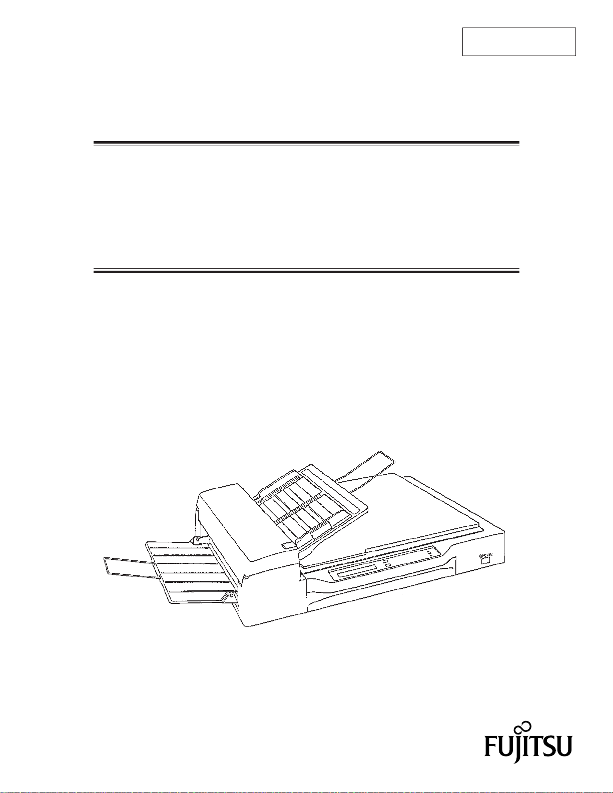
M3097E+ AND M3097G
IMAGE SCANNER
OPERATOR’S GUIDE
+
Page 2

REVISION RECORD
Edition
01
Date published
Jan., 1996
Revised contents
First eddition
Specification No.: C150-E048-02EN
This digital apparatus does not exceed the Class A limit for radio noise emissions from digital apparatus set out in the Radio
interference Regulations of the Canadian Department of Communications.
Le présent appareil numérique n’ément pas de bruits radioélectriques dépassant les limites applicables aux appareils
numériques de la classe A prescridtes dans le Réglesment sur le brouillage radioélectrique édicté par le ministere des
Communications du Canada.
This equipment has been tested and found to comply with the limits for a Class A digital device, pursuant to Part 15 of the
FCC Rules. These limits are designed to provide reasonable protection against harmful interference when the equipment
is operated in a commercial environment.
This equipment generates, uses, and can radiate radio frequency energy and, if not installed and used in accordance with
the instruction manual, may cause harmful interference to radio communications. Operation of this equipment in a residential
area is likely to cause harmful interference in which case the user will be required to correct the interference at his own
expense.
The contents of this manual is subject to change without
prior notice.
All Rights Reserved,
Copyright ©1996 FUJITSU LIMITED
i
Page 3

IMPORTANT NOTE TO USERS
READ CAREFULLY ALL OF THIS MANUAL BEFORE USING THIS PRODUCT. IF NOT
USED CORRECTLY, UNEXPECTED DAMAGES MAY BE CAUSED TO THE USERS OR
THE BYSTANDERS.
Conventions for Alerts
This manual uses the following coventions for alerts to prevent physical or property damages to
users or bystanders.
CAUTION indicates that either minor or moderate personal
!
CAUTION
IMPORTANT IMPORTANT indicates information that helps the user use the
ii
NOTICE
!
injury may occur if the user does not perform the procedure correctly.
NOTICE indicates that inconvenience to the user such as damages
to the product, equipment, data, and/or other property may occur if
the user does not pay attention or perform the procedure correctly.
product more effectively.
Page 4

CONTENTS
page
CHAPTER 1 PREFACE .................................................................................................... 1-1
CHAPTER 2 COMPONENTS ........................................................................................... 2-1
2.1 Checking the Components........................................................................................... 2-1
2.2 Part Names and Functions ........................................................................................... 2-2
2.2.1 Exterior view of image scanner........................................................................... 2-2
2.2.2 Functions of each part ......................................................................................... 2-3
2.3 Operator Panel Functions ............................................................................................ 2-4
2.3.1 Indicators ............................................................................................................. 2-5
2.3.2 Buttons and liquid crystal display screen (M3097E+) ........................................ 2-5
2.3.3 Buttons and liquid crystal display screen (M3097G+) ..................................... 2-11
2.3.4 Messages ........................................................................................................... 2-11
CHAPTER 3 INSTALLATION AND CONNECTIONS ................................................ 3-1
3.1 Precautions .................................................................................................................. 3-1
3.2 Removing the Carrier Fixing Bracket ......................................................................... 3-2
3.3 Connections ................................................................................................................. 3-3
3.4 Mounting the Stacker .................................................................................................. 3-5
CHAPTER 4 OPERATIONS ............................................................................................. 4-1
4.1 Turning on the Power .................................................................................................. 4-1
4.2 Reading a Document in Flatbed Mode........................................................................ 4-2
4.2.1 Reading a standard-size document...................................................................... 4-2
4.2.2 Reading a page from a thick book....................................................................... 4-3
4.2.3 Reading a document larger than the document board ......................................... 4-4
4.3 Reading Documents in ADF Mode ............................................................................. 4-5
iii
Page 5

CHAPTER 5 MAINTENANCE ......................................................................................... 5-1
5.1 Removing Jammed Documents................................................................................... 5-1
5.2 Notes on Daily Use...................................................................................................... 5-2
5.3 Cleaning....................................................................................................................... 5-2
5.3.1 Cleaning the document cover, document holding pad, and document bed......... 5-2
5.3.2 Cleaning the ADF................................................................................................ 5-3
5.3.3 Cleaning the coupled feed roller ......................................................................... 5-4
5.3.4 Cleaning the mirror ............................................................................................. 5-4
5.4 Replacing the Lamp Unit ............................................................................................ 5-5
5.5 SCSI Address Setting (M3097G+).............................................................................. 5-9
5.6 Replacing the Pad...................................................................................................... 5-10
5.7 Document counter display and reset ......................................................................... 5-11
CHAPTER 6 TROUBLESHOOTING .............................................................................. 6-1
APPENDIX .............................................................................................................................A-1
A.1 Installation Specifications ..........................................................................................A-1
A.2 External Dimensions ..................................................................................................A-2
iv
Page 6

FIGURES
page
Figure 2.1 Received components ...................................................................................... 2-1
Figure 2.2 M3097E+/G+ parts names............................................................................... 2-2
Figure 2.3 M3097E+ operator panel ................................................................................. 2-4
Figure 2.4 M3097G+ operator panel................................................................................. 2-4
Figure 4.1 Flatbed reading ................................................................................................ 4-3
Figure 4.2 Removing the document cover ........................................................................ 4-4
Figure 4.3 ADF paper chute setting .................................................................................. 4-6
Figure 4.4 Loading the document ..................................................................................... 4-8
Figure 5.1 Removing jammed documents......................................................................... 5-1
Figure 5.2 Cleaning the document cover, document holding pad, and document bed ..... 5-2
Figure 5.3 Cleaning the ADF ............................................................................................ 5-3
Figure 5.4 Lamp unit removal 1........................................................................................ 5-6
Figure 5.5 Lamp unit removal 2........................................................................................ 5-6
Figure 5.6 Lamp unit replacement .................................................................................... 5-7
Figure 5.7 Inserting the glass ............................................................................................ 5-8
Figure 5.8 Removing the Pad.......................................................................................... 5-10
Figure A.1 External dimensions.........................................................................................A-2
v
Page 7

TABLES
page
Table 1.1 The differences between the M3097E+ and the M3097G+............................. 1-1
Table 6.1 Check items ..................................................................................................... 6-1
Table A.1 Installation specifications ................................................................................A-1
Reader Comment Form
vi
Page 8

CHAPTER 1 PREFACE
This manual describes how to operate the M3097E+ and M3097G+ image scanners. The
M3097E+ now supports a document counter function. The M3097G+ similarly supports a new
document counter and also features an 8-bit grayscale function. An image scanner optically
reads image information from a document and outputs the information to the host system. The
differences between the M3097E+ and the M3097G+ image scanners are listed in table 1.1.
Table 1.1 The differences between the M3097E+ and the M3097G+
Model number
M3097E+
M3097G+
This manual should be read before operating the image scanner to ensure correct operation.
Note on Copyright Act
This document cannot be reproduced or copied for any use other than private without the
author’s permission.
Interface
RS232C
+
VIDEO
SCSI2
Shipping
destination
North America
Europe
North America
Europe
Image size
A3 size or
double-letter
size
Automatic
document feeder
Yes
1–1
Page 9

This page is intentionally left blank.
1–2
Page 10
CHAPTER 2 COMPONENTS
2.1 Checking the Components
2.2 Part Names and Functions
2.3 Operator Panel Functions
After unpacking image scanner, confirm that all the components have been received. This
section describes the components of the image scanner and their functions.
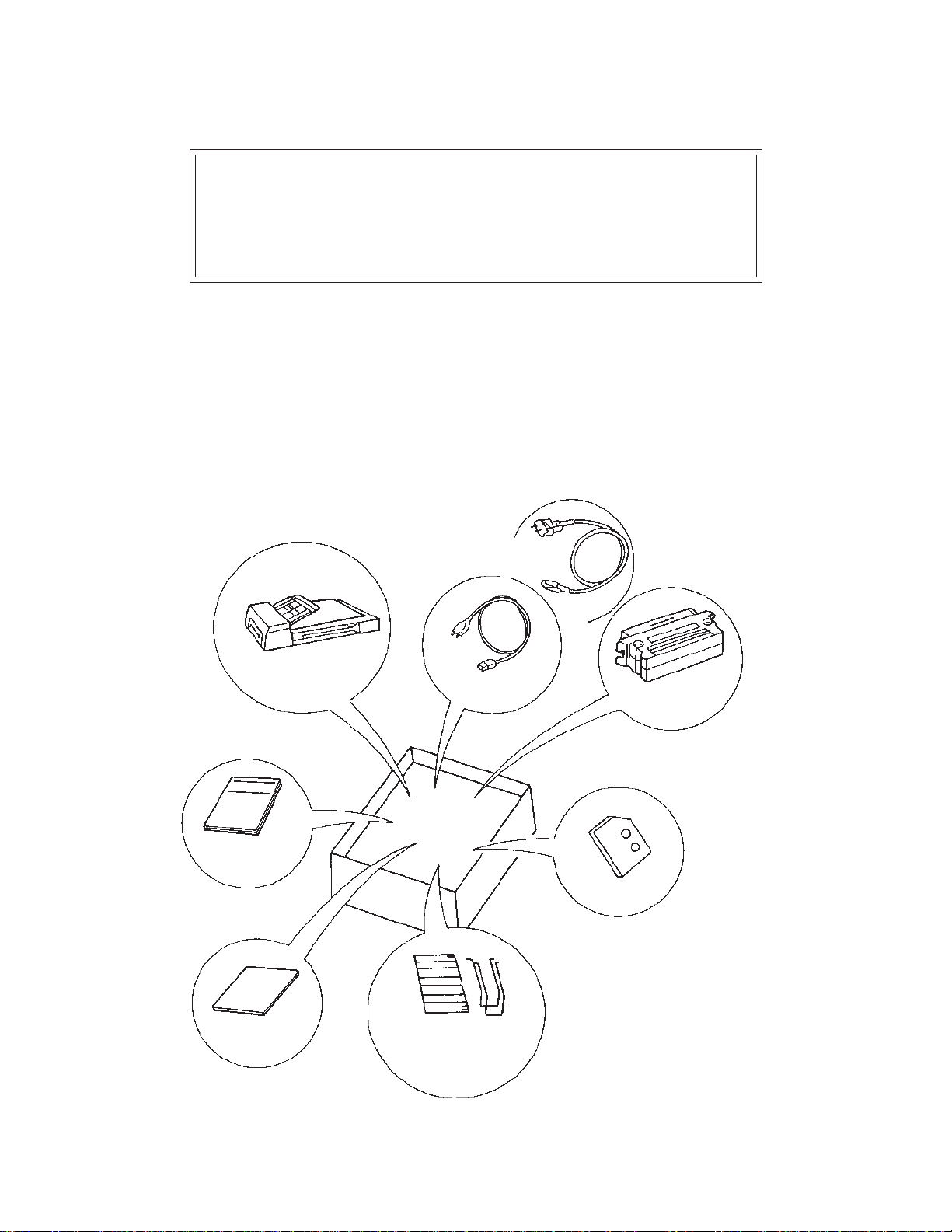
2.1 Checking the Components
These high precision components must be handled with care. Confirm
that all the components shown in figure 2.1 have been received. If
any component is missing, please contact your local Fujitsu sales
person.
Power cable
for Europe
Image scanner
Operator’s Guide
(this manual)
Inspection
report
Power cable for
North America
One stacker and
two extensions
Terminator
(for M3097G+)
Ten Pads
Figure 2.1 Received components
2–1
Page 11
2.2 Part Names and Functions
This section shows the exterior view of image scanner. This section
also provides names of each part and describes their functions.
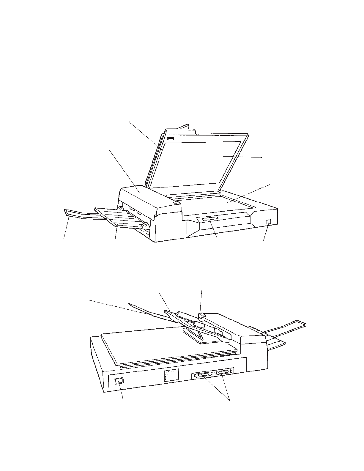
2.2.1 Exterior view of image scanner
The image scanner can read a document of A3 or double-letter size at
maximum.
Document cover
Automatic document
feeder (ADF)
Document
holding pad
Document
bed
Extension
Extension
Stacker
Power inlet
ADF paper chute
Operator panel
ADF lever
Power switch
Interface connectors
2–2
Figure 2.2 M3097E+/G+ parts names
Page 12

2.2.2 Functions of each part
Document cover: Closed over and holds a document to be
Document bed: A document to be read is placed on the
Document holding pad: Presses a document to the document bed.
Automatic document feeder (ADF):
Stacker: Stacks the read documents.
Extension: Keeps the stacked documents from
Power switch: Turns the power on or off.
Operator panel: Used to control image scanner opera-
ADF paper chute: Holds the documents to be fed by the
read.
bed also called Flatbed (FB).
Automatically feeds documents to the
reading position.
overhanging.
tions. See the next section for details of
the functions.
automatic document feeder.
ADF lever: Opens or closes the automatic document
feeder to remove documents jammed in
the feeder.
Power inlet: To be connected to an AC power outlet
with the power cable.
Interface connectors: To be connected to the host system with
interface cables.
2–3
Page 13
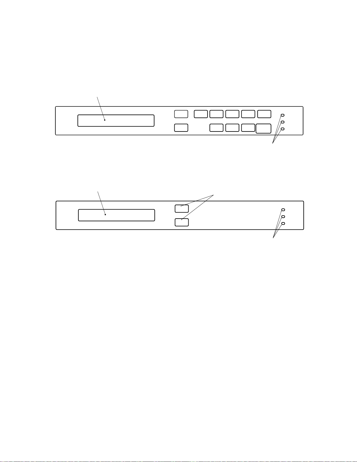
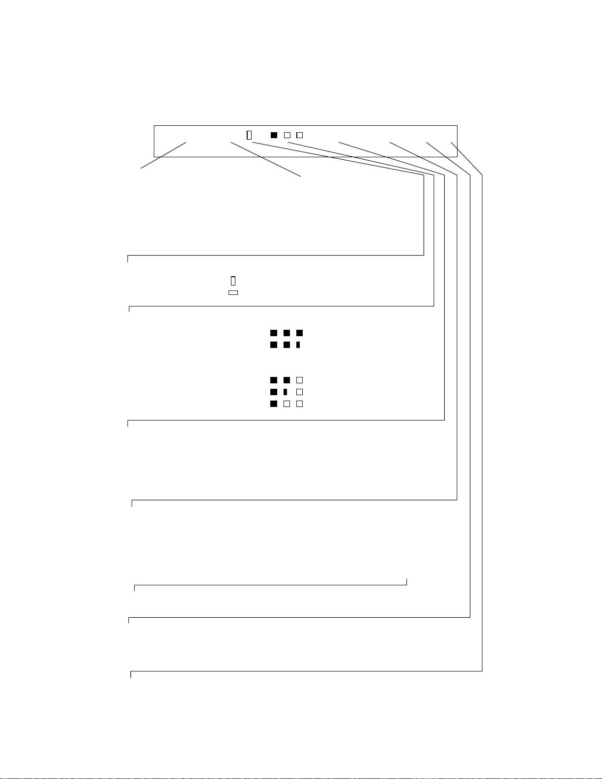
2.3 Operator Panel Functions
The operator panel has indicators and a liquid crystal display screen
for displaying image scanner status. The operator panel also has
operation buttons.
Liquid crystal display screen
Liquid crystal display screen
Buttons
Mode 1
Mode 2
ADF
Size
Landscape
Figure 2.3 M3097E+ operator panel
Buttons
Mode 1
Mode 2
Figure 2.4 M3097G+ operator panel
Density
Halftone
Resolution
Document
Stop
Start
Power
Ready
Check
Indicators
Power
Read
Check
Indicators
2–4
Page 14

2.3.1 Indicators
The meaning of each indicator is as follows:
Power indicator (Green):
Lights to indicate the power is on.
Ready (for reading) indicator (Green) (M3097E+):
Lights when the image scanner becomes ready to read a document in the manual mode. This indicator turns off when the
start button is pressed to read a document.
Read (reading in progress) indicator (Green) (M3097G+):
Lights to indicate reading is in progress.
Check (device check) indicator (Yellow):
Lights if a device error occurs which may result in a service
call. An error message is displayed on the liquid crystal display
screen. This indicator blinks if a document is jammed in the
automatic document feeder. This indicator turns off when the
jammed documents are removed from the feeder and the feeder
is closed.
2.3.2 Buttons and liquid crystal display screen (M3097E+)
The function of each button is as follows:
Start button:
Read operation can be started in either manual or automatic
mode. To start reading in manual mode, press this button while
the ready indicator is lit.
• Manual mode: Reading is started by the start button.
• Automatic mode: Reading is started by a command from
the host system.
Stop button:
This button is effective regardless of whether the scanner is in
manual or automatic mode. Press this button to stop the read
operation. When this button is pressed, the image scanner
operates as follows:
• Reading in flatbed mode: Reading is immediately stopped.
• Reading in ADF mode: Reading is immediately stopped
and documents being fed are ejected to the stacker.
After cleaning a jam, press the stop button to clear the
“Paper Jam” message displayed on the screen. The
ready screen will then be displayed to indicate that the
scanner is ready to read.
2–5
Page 15
Liquid crystal display screen
The screen has two message lines. The current read mode
status is displayed in the upper line, and messages and the
modes set by the buttons are displayed in the lower line.
Upper line
Lower line
AFDA004>.L4
Reading mode Display
Flatbed
Automatic document feeder
: FB
: ADF
Doument orientation Display
Portrait:
Landscape:
:
:
Density
Very dark
Dark
Dynamic threshold
Simplified dynamic threshold
Normal
Light
Very light
Display
:
:
:
AT
:
AT2
:
:
:
Size
Double-letter size
Letter size
Legal size
A3 size
A4 size
If the optional PC board
1
}
is installed
Display
: DL
: LT
: LG
: A3
: A4
Resolution
400 dpi
300 dpi
240 dpi
200 dpi
Halftone processing
No halftone processing
Dither processing
Error diffusion processing
Automatic separation (by dither processing)
Automatic separation (by error diffusion processing)
Display
: 400
: 300
: 240
: 200
Display
:
: HT1
: HT2
: LP1
: LP2
If the optional PC
board is installed
If the optional PC board is not installed, automatic separation cannot be done.
Line or photo selection Display
To read a photo document
To read a line document
: P.
: L.
Image processing board (optional) installed.
No
Yes
:
: >
2–6
Page 16

The ADF, size, density, resolution, landscape, half-tone, document,
and mode 1 and 2 buttons described below are effective unless otherwise specified by the host system.
Automatic document feeder (ADF) button:
Selects whether to feed documents automatically by ADF or
manually on the flatbed. When this button is pressed, the lower
line is displayed as shown in Screen 1. Each time this button is
pressed, “FB” or “ADF” starts blinking in turn, and the read
operation status displayed in the upper line changes accordingly.
Screen 1 — The upper line shows a typical example.
Upper line
Lower line
AFDA
eRBF:da
004
FDA
Blinking
Size button:
Selects a document size. When this button is pressed, the lower
line is displayed as shown in Screen 2. Each time this button is
pressed, “DLT”, “LT”, “LG”, “A3”, or “A4” starts blinking in
turn, and the size displayed on the upper line changes accordingly.
Screen 2 — The upper line shows a typical example.
Upper line
Lower line
LFDA
:eziSLLG
TD
TL 4A3A
004
Blinking
If the direction indicated on the upper line is “ ”, only “LT”
or “A4” can be selected.
>.L4
>.LG
2–7
Page 17
Density button:
Selects a density for the read operation. When this button is
pressed, the lower line is displayed as shown in Screen 3. Each
time this switch is pressed, the blinking part in the lower line
changes, and the density indicated on the upper line changes
according to the blinking part.
Screen 3 — The upper line shows a typical example.
Upper line
Lower line
LFDA
neD: A
. Tu
Blinking
004
The lower line is displayed as shown below. (See the beginning
of this section for the upper line.)
Display (lower line) Explanation
Very dark
Blinking
order
If the
optional
PC board
is installed:
AT ( Au o21
{
AT (Au o
t)
t)
Dark
Dynamic threshold
Simplified dynamic threshold
Normal
Light
Very light
Resolution button:
Selects a resolution for the read operation. When this button is
pressed, the lower line is displayed as shown in Screen 4. Each
time this button is pressed, “400”, “300”, “240”, or “200” starts
blinking in turn, and the resolution indicated on the upper line
changes accordingly.
otA(
>.PG
)1
2–8
Screen 4 — The upper line shows a typical example.
Upper line
Lower line
LFDA
G
seR004:.
Blinking
0032042
004
>.P
00
Page 18

Landscape button:
Specifies whether reading is done in landscape or portrait mode.
When this button is pressed, the lower line is displayed as
shown in Screen 5. Each time this button is pressed, the blinking part changes in turn, and the mode indicated on the upper
line changes accordingly.
Screen 5 — The upper line shows a typical example.
Upper line
Lower line
LFDA
:eziSLTLD
GLT4A3A
004
Explanation:
Display
: Landscape mode. This mode can be selected only if
the document size displayed on the upper line is LT or
A4.
: Portrait mode.
Halftone button:
Specifies whether to perform halftone processing (dither or
error diffusion). When this button is pressed, the lower line is
displayed as shown in Screen 6. Each time this button is
pressed, the blinking part changes in turn, and the halftone
indication on the upper line changes accordingly.
Screen 6 — The upper line shows a typical example.
Upper line
Lower line
LFDA
tflaHO:eno
Blinking
Not displayed unless the
optional PC board is installed.
004
THFF
1
Blinking
1TH
>.PT
>.LG
Blinking
order
Explanation:
Display (lower line)
“OFF” blinking
“HT1” blinking
“HT2” blinking
(changed from HT1)
“LP1” blinking
(changed from HT2)
“LP2” blinking
(changed from LP1)
Explanation
: Line Art (Halftone
Processing off)
: Halftone processing
(dither)
: Halftone processing
(error diffusion)
: Automatic separation
(dither)
: Automatic separation
(error diffusion)
Select one of these settings to
read data such as photographs,
illustrations, or colored maps.
If photographs and characters
are mixed in a document, the
characters are read clearly and
the photographs are read in
halftone. This setting is only
available if the optional PC
board is installed.
2–9
Page 19

Document button:
Selects the type of document. When this button is pressed, the
lower line is displayed as shown in Screen 7. Each time this
button is pressed, “LINE” or “PHOTO” starts blinking in turn,
and the document selection indication displayed on the upper
line changes accordingly.
Screen 7 — The upper line shows a typical example.
Upper line
Lower line
COD.L:.
LFDA
enL(
i .(Photo)
003
P)
Blinking
Explanation:
Display (lower line) Explanation
P.(Photo) : For light adjustment or when there is a
dark background color on the document,
select P. (Photo).
L.(Line) : Select this setting to read line drawings.
IMPORTANT
When L (Line) is selected, the top 3-mm part of the read
area should be left blank (grounding color) by specifying
a drop-out color.
Mode 1 button : See Sections 5.3.4, 5.4 and 5.5.
Mode 2 button : See Sections 5.3.4, 5.4 and 5.5.
When error messages are displayed on
liquid crystal display screen, press this
button to enable the read operation.
1TH
>.PG
2–10
Page 20

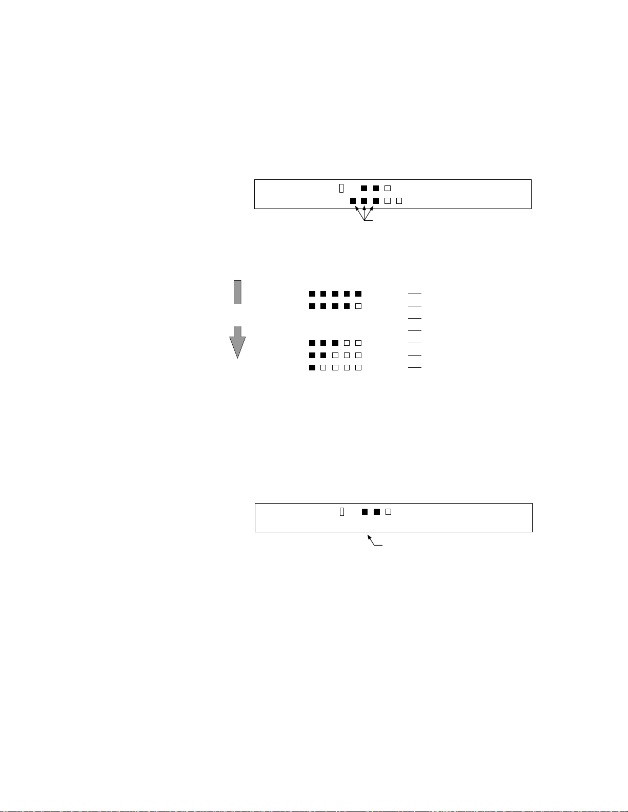
2.3.3 Buttons and liquid crystal display screen (M3097G+)
Liquid crystal display screen: Displays messages only.
The mode buttons have the following functions:
Mode 1 button: See Section 5.3.4, 5.4 and 5.5.
Mode 2 button: See Section 5.3.4, 5.4 and 5.5.
When error messages are displayed on liquid crystal
display screen, press this button to enable the read
operation.
2.3.4 Messages Error messages (temporary errors)
If a temporary error occurs in the scanner, one of the following messages is displayed.
epaPpmEryt
This message is displayed if there is no more paper on the
ADF paper chute during a read operation in ADF mode.
Fill the ADF paper chute with paper. To enable the read
operation, for the M3097E+, press the stop button, for the
M3097G+, press the Mode 2 button.
paPaJrem
This message is displayed if a document is jammed in the
ADF. See section 5.1 for removing jammed documents.
AoC–FDOrevnep
This message is displayed if the ADF is not closed
completely. Close the ADF completely, and enable the
read operation.
LC–pm
a
ewoP
This message is displayed if the ADF is open for lamp
replacement when the power is on. Turn off the power,
and close the ADF completely.
revo
ffOr
!!
nepO
Page 21

Device errors
One of the following messages is displayed if an device errors in the
scanner. If one of the following error messages is displayed, turn the
power off and then on again. If the same message is displayed again,
contact your service representative.
citplAlamraO
etaeHalArmr
eMinahcAlacmral
uFes
mlArauFes–eHreta
–
mlAraLpma
FtoMBromlArauFes–
DAtoMFromlArauFes–
Operation status messages
Operation status is displayed as shown by the following messages:
aWgnimrNpu–!!wo
The power is on.
RwoNniaegd!
Reading is in progress.
2–12
!Please clean–up!
The glass plate is dirty. Clean it. In addition, clean the
mirror as explained in Section 5.3.4.
l ase clean Pic –rol lereP
The pick roller is dirty. Clean it as explained in Section
5.3.2.
LFDA
e
da
yR
The scanner is ready for operation in the manual mode.
Press the start button to start the read operation.
c nner ReadyaS
The scanner is ready for operation.
k
004
HG
M3097E+
M3097G+
Page 22

CHAPTER 3 INSTALLATION AND CONNECTIONS
3.1 Precautions
3.2 Removing the Carrier Fixing Bracket
3.3 Connections
3.4 Mounting the Stacker
This chapter explains how to install and connect the image scanner.
3.1 Precautions
Do not install the image scanner in the following places and environments. See the appendix A.1 “Installation Specifications” for the
information such as size of installation space.
Place the scanner away from electrical noise
sources and strong magnetic fields. If the
image scanner is used near an air conditioner,
copying machine, or TV set, the scanner may
operate incorrectly.
Keep the scanner out of the sun and away
from heaters. These environments may
shorten scanner life or cause hardware
failures.
Do not install the scanner in a place where
vibrations may occur. This environment may
cause hardware failures or may cause the
scanner to operate incorrectly.
Do not install the scanner in a humid, dusty,
or damp places. These enviroments may
shorten scaner life or cause hardware failures. Do not place the image scanner where
liquid spills may occur. Place it on a flat and
even surface.
Be aware of static electricity. If static
electricity is generated, the scanner may
operate incorrectly. Be sure that the flooring
and the desk are made of materials that do
not generate static electricity.
3–1
Page 23

3.2 Removing the Carrier Fixing Bracket
To keep the scanner from being damaged during shipping, the carrier
unit is fixed with a bracket. After placing the carrier unit at the
installation place, remove this bracket as explained below.
1 Place the image scanner on the edge of the desk top so that the left side (where ADF
is placed) of the scanner extends from the desk top. Do not set the image scanner
upside down or on its side.
×
2 Remove the carrier fixing bracket from position A. Then install the carrier fixing
bracket at position B.
Automatic document feeder
×
Operator panel
3–2
B
A
Carrier fixing bracket
Page 24

3.3 Connections
Connect the image scanner using the following procedure.
1 Set the power switch to off.
2 Connect the power cable.
Connect the power cable to the power inlet on the back of the image scanner.
Connect the other end of the power cable to a power outlet.
Power switch
Power inlet
Power cable
3 Connect the interface cables (for M3097E+).
Connect the interface cables to the interface connectors and fasten the cables
with catches and screws as shown below.
Connect the other end of each interface cable to the host computer.
Back of the image scanner
Power outlet
for North America
for Europe
Interface cable for RS232C
Catches
Interface cable for video
Screws
To the host system
3–3
Page 25

(M3097G+)
Connect the interface cables to the interface connectors and fasten the cables
with the catches. Connect the other ends of the cables to the host system. If the
image scanner is at the terminal side, connect the terminator.
Back of the image scanner
Catches
Catches
NOTICE
Terminator
If the image scanner is at
Interface cables
To the
host
system
the terminal side, connect
the terminator to the
connector to which an
interface cable is not
connected.
Use shielded interface cables to prevent harmful interferance or
avoid receiving interferance that may cause undesired operation.
3–4
Page 26

3.4 Mounting the Stacker
Mount the stacker and extensions using the following procedure.
1 Mount the stacker.
Hook the pins on the stacker to the claws on the image scanner.
Stacker
Pin
Claw
2 Mount the extensions.
Mount extensions to the stacker and to the ADF paper chute.
Extension
Extension
ADF paper chute
Stacker
3–5
Page 27

This page is intentionally left blank.
3–6
Page 28

CHAPTER 4 OPERATIONS
4.1 Turning on the Power
4.2 Reading a Document in Flatbed Mode
4.3 Reading Documents in ADF Mode
Documents can be read in the flatbed mode or automatic document feeder (ADF) mode. In the
flat-bed mode, each document is placed on the document bed and is read one by one. In ADF
mode, documents are fed and read automatically.
This section explains how to turn on the power and how to read documents.
4.1 Turning on the Power
This section explains how to turn on the power.
Press the power switch. When the power is turned on, the power
indicator is lit.
Power indicator
Press the power switch again to turn off the power.
Power switch
4–1
Page 29

4.2 Reading a Document in Flatbed Mode
This section explains how to read a document placed on the document
bed.
!
CAUTION
4.2.1 Reading a standard-size document
High luminance: Do not look directly at the light source during
If the size of the document is smaller than the document bed, read the
document using the following procedure:
1 Open the document cover.
2 Place the document face down on the document board. Correct
any curled or folded parts of the document.
3 Position the long side (in landscape mode) or the short side (in
portrait mode) of the document to the left side of the document
bed.
4 Position the left top of the document to the reference mark. If the
document is not placed correctly, reading cannot be done correctly.
read operation. Keep the document cover in
place.
5 Close the document cover slowly. If the document cover is
closed too quickly, the document may move.
6 For M3097E+, select a reading mode from the operator panel and
start the read operation. For the M3097G+, the scanner starts the
read operation by a command from the host system. Do not press
on or open the document cover during the read operation.
7 After reading, open the document cover to remove the document.
4–2
Page 30

Reference mark
Document
Document cover
Operator panel
Document bed
Figure 4.1 Flatbed reading
Landscape mode
3
Long side
4.2.2 Reading a page from a thick book
To read a page from a thick book, remember the following points:
1 Do not close the document cover forcibly. Keep the cover open
for reading.
Portrait mode
Document bed
3
Short side
Document
2 Any document parts that are not in contact with the glass will not
be read correctly.
3 Do not move the document during the read operation.
4–3
Page 31

4.2.3 Reading a document larger than the document board
If the size of the document is larger than the document board, read the
document using the following procedure:
1 To remove the document cover, remove the screw from the
document cover.
2 Place the document face down on the document bed.
3 Place the document cover over the document.
4 Read the document.
5 After the read operation, remove the document, replace the
document cover. Mount the document cover to the original
position, fasten the document cover with the screw, and close the
document cover.
Document cover
NOTICE
Screw
Document bed
Figure 4.2 Removing the document cover
Do not remove the document cover for any other purpose. Do not
use a different screw to fix the document cover to the scanner.
4–4
Page 32

4.3 Reading Documents in ADF Mode
This section explains how to read documents using the automatic
document feeder. If the following steps are not closely followed, a
feed error may occur.
After documents have been read in ADF mode, a squeaking noise is
sometimes heard. This is not a problem as the noise is caused by the
self-cleaning action of the rollers.
1
Check the documents as follows:
(a) Paper quality
• Wood-free paper.
• PPC paper; Specified by XEROX Corporation.
(b) Paper weight
• 13.9 lbs to 34 lbs
(c) Paper size
• Letter, Double Letter, Legal, A3, A4, A5, B4, B5, B6, A6
(d) Items to avoid
• The following paper cannot be fed by ADF appropriately.
– Paper with a clip or staple.
– Paper that has ink that is not dry.
– Paper thickness is not constant, such as an envelope.
– Paper that has large rumples or curl.
– Paper that has folds or tears.
– Tracing paper.
– Coating paper.
– Carbon paper.
– Paper that is smaller than A6 size or larger than A3
width.
– Items other than paper, such as clothes, metal sheet, or
OHP film.
– Photographic paper.
– Paper that has perforations on its side.
– Paper that has a shape other than square.
– Paper that is very thin.
4–5
Page 33

2 Pull up the ADF paper chute as follows:
• Hold the document cover with one hand and pull up the ADF
paper chute with the other hand to unlock the ADF paper chute.
ADF paper chute
Document cover
Figure 4.3 ADF paper chute setting
3 Fan the documents as follows:
• Take a 15 to 20 mm thickness of documents. Lightly hold both
ends with both hands. Bend the documents into an arch as
shown below.
• Then hold the documents tightly with both hands, and
straighten the documents. The center of documents swell and
air is introduced between the documents.
• Repeat this operation two or three times.
• Turn the documents 90°, and repeat the operation again.
15 to 20 mm
4–6
Page 34

4 Take documents to be placed in the ADF paper chute. The
thickness of the documents to be placed in the ADF paper chute is
limited depending on the size of the documents as follows:
A4 or letter size or smaller: 8 mm or less
Size larger than A4: 4 mm or less
5 Angling the documents
Angle the document edges as follows:
• Place the documents face down with the top to the left as
shown in A. The long side is the top for landscape mode and
the short side is the top for portrait mode.
• Lift the documents holding the both ends with both hands.
• Hold the documents tightly with your left hand and bend the
documents as shown in B.
• Grip tightly with your right hand, loosen the grip of your left
hand, and straighten the documents as shown in C.
• Repeat these operations until the top is angled 20° or less as
shown in D.
Top
A
B
C
(For portrait mode)
D
20° or less
4–7
Page 35

6 Open the right and left guides of the ADF paper chute about 5
mm wider than the document width.
7 Place the documents face down onto the ADF paper chute with
the top edges facing the automatic feeder hole.
8 Adjust the guides to the document sides. Skewing may occur if
there is a gap between the guides and documents.
9 Slide the documents down until they touch the far end of the
automatic feeder opening. If the documents hit the far end hard,
two or more pages may be fed at once. Make sure that the upper
end of documents are not turned.
10 For the M3097E+, select the reading mode from the operator
panel and start the read operation. For the M3097G+, the scanner
starts the read operation by a command from the host system. If
an incorrect document size or mode (portrait or landscape) is
selected, the document may not be read entirely.
11 After reading, remove the documents from the stacker.
Automatic document feeder
Guide
Figure 4.4 Loading the document
Portrait Landscape
Guide
Documents
ADF paper chute
Guide lever
Automatic document feeder
ADF paper chute
4–8
Short side
Long side
Documents
Page 36

CHAPTER 5 MAINTENANCE
5.1 Removing Jammed Documents
5.2 Notes on Daily Use
5.3 Cleaning
5.4 Replacing the Lamp Unit
5.5 SCSI Address Setting (M3097G+)
5.6 Replacing the Pad
5.7 Document counter display and reset
This section explains how to remove jammed documents, and provides notes on daily use and
cleaning.
If "Please clean-up!!" is displayed on the operator panel during the read operation, clean the
mirror as explained in Section 5.3.4.
If "Please clean Pick-roller" is displayed, clean the pick roller as explained in Section 5.3.2.
5.1 Removing Jammed Documents
If documents jam while being fed by the ADF, remove the jammed
documents as follows:
1
Remove the documents from the ADF paper chute.
2
Pulling up the ADF lever, open the automatic document feeder.
3
Remove the jammed documents.
4
Close the ADF to the ADF lever.
ADF lever
Automatic document feeder (ADF)
Figure 5.1 Removing jammed documents
5–1
Page 37

5.2 Notes on Daily Use
Note the following points on daily use:
• The image scanner requires one to three minutes to warm up after
the power has been turned on. During this time, the message
“Warming-up Now!!” is displayed on the screen.
• Do not look directly at the light source during the read operation.
Keep the document cover in place.
• See Section 5.3 “Cleaning”, to clean the document cover, document
holding pad, document bed, and the automatic document feeder.
IMPORTANT Especially, clean the ADF periodically. For cleaning cycle, see
Section 5.3.2 “Cleaning the ADF”.
5.3 Cleaning
This section explains how to clean the image scanner.
5.3.1 Cleaning the document cover, document holding pad, and document bed
• Use a dry cloth or a cloth with a neutral cleanser or ethyl alcohol to
remove dirt from the document cover, document holding pad, and
document bed.
NOTICE
Document cover
Document holding pad
Do not use organic solvents such as a thinner.
• Make sure that no liquid enters the scanner from the edges of the
document bed glass.
Cloth
Document bed
Neutral cleanser
or ethyl alcohol
Thinner
Figure 5.2 Cleaning the document cover, document holding pad, and document bed
5–2
Page 38

5.3.2 Cleaning the ADF
Clean the ADF once every 5,000 pages. The cycle depends on the
types of documents used (page quality, a level of toner fusing on
paper).
1 Pull the ADF lever up to open the ADF.
2 Use the dry cloth or a cloth with ethyl alcohol to softly remove
dirt and dust as follows.
Pad: Wipe the pad in a downward direction (indi-
cated by the arrow). Be careful not to hook
the pick spring when wiping.
Glass: Wipe the glass lightly. See Section 5.4,
“Replacing the Lamp Unit” to clean the
bottom of the glass.
Pick rollers (two): Wipe the rollers softly. Be careful not to
damage the surface of the rollers. If the toner
adheres to the roller, it may affect the paper
feed performance. Clean the rollers well.
Feed roller and coupled feed roller:
Wipe the rollers softly. Be careful not to
damage the surface of the rollers. If the toner
adheres to the roller, it may affect the paper
feed performance. Clean the rollers well. For
details of the coupled feed roller, see Section
5.3.3.
Ejection roller and coupled ejection roller:
Wipe the rollers softly. Be careful not to
damage the surface of the rollers. If the toner
adheres to the roller, it may affect the paper
feed performance. Clean the rollers well.
Guide shaft (white part):
Wipe the guide shaft softly.
3 Close the ADF to lock the ADF lever.
Ejection roller (Clean the roller
Pick spring
Feed roller
on the opposite side also.)
Pick rollers
ADF lever
Pad
Automatic document feeder
Guide shaft (white part)
Glass
Figure 5.3 Cleaning the ADF
Coupled feed roller
(See section 5.3.3)
5–3
Page 39

5.3.3 Cleaning the coupled feed roller
1 Pull the ADF lever up to open the ADF.
2 Pull the ADF lamp replacement lever up while pushing the lever
in the direction indicated by the arrow in Figure 5.4.
3 Clean the surface of the coupled feed roller by the cloth with
ethyl alcohol.
NOTICE
5.3.4 Cleaning the mirror
If the coupled feed rollers are excessively pushed in the direction of
the arrow above during cleaning, the automatic document feed
performance may be affected.
1 Cleaning the mirror:
2 How to clean the mirror:
Remove the glass plate from the automatic document feeder with
the same procedure as that for lamp replacement. Do not move
the carrier unit during work. Dust may fall on the mirror. When
installing the lamp unit, if the automatic document feeder and
mirror are dirty, clean them before final installation and before
putting the glass plate back on.
Wipe the mirror using the blower. When the mirror is very dirty,
use a dry cloth or a cloth with alcohol. If the mirror is strongly
wiped or dirty cloth is used, the mirror may be damaged.
5–4
Page 40

5.4 Replacing the Lamp Unit
Hot: Replace the lamp unit in the following procedure.
If an optical alarm occurs, and the following message is displayed,
replace the lamp unit as follows.
• Turn off the power once. Then, turn on the power while pressing
the mode 1 button. For M3097G+, press the mode 2 button so that
"Lamp Exchange" blinks. If the surface temperature of lamp rises,
the following message is displayed:
citplAaraOml
lPesaet
cmaLf
• After the surface temperature of the lamp lowers, the carrier moves
to the replacement position. The lamp remains unlit. Confirm that
the following message is displayed.
ewoPffOr!!
Then, turn off the power.
wa i
nposigilofo
5–5
Page 41

• Pull the ADF lever up and open the ADF.
• Pull the ADF lamp replacement lever up while pushing the lever in
the direction indicated by the arrow in Figure 5.4.
• Hold the lamp unit levers and pull the glass up. Wipe the bottom
surface of the glass if it is dirty.
Automatic document feeder
ADF lever
ADF lamp replacement lever
Lamp unit levers
Glass
Figure 5.4 Lamp unit removal 1
5–6
Lamp unit levers
Lamp unit
Figure 5.5 Lamp unit removal 2
Page 42

• Then carefully pull it up with the front and ( 1 in Figure 5.6) first
and the back and ( 2 in Figure 5.6) next. If the levers are pulled up
carelessly, the lamp may be broken.
!
CAUTION
Lamp unit levers
Lamp unit insert
direction (vertical)
Hot: The lamp surface may be very hot. Be careful not to touch
the lamp surface.
2
A
Lamp unit
1
A
Arrows indicating the
lamp unit insert position
Figure 5.6 Lamp unit replacement
• Obtain a new lamp unit.
• Hold the new lamp unit with both hands. Insert it in the insertion
slits with the back end first and the front and second by pressing
points indicated with A in Figure 5.6.
• After completely inseting the lamp unit, hold the lamp unit levers
with both hands and insert both ends of the glass into the openings.
IMPORTANT If the lamp unit is not inserted completely, the carrier may not
operate. The ADF may not close if the both ends of the glass are
not inserted in the openings correctly.
5–7
Page 43

Glass
Figure 5.7 Inserting the glass
• Close the ADF to lock ADF lever.
Levers
Openings
5–8
Page 44

5.5 SCSI Address Setting (M3097G+)
Press the power switch while pressing the mode 1 button. The liquid
crystal display unit displays the following screen.
ISCSLDEpmanahcxegI
Blinking
Press the mode 2 button to shift the blinking position. To set a device
address, press the mode 1 button while “SCSI ID” is blinking.
The liquid crystal display screen displays this screen. A value from 0
to 7 is displayed in turn each time the mode 1 button is pressed. Press
the mode 2 button to store the value when an appropriate value is
displayed.
Confirm that the following screen is displayed, and turn off the power.
ISCSDI0
ewoPffOr!!
5–9
Page 45

5.6 Replacing the pad
(1) Pull up the ADF open and close lever to open the ADF.
(2) Remove the four screws shown in Figure 5.8 to remove the two
(3) Install the pad by reversing the removal procedure.
pads.
5–10
NOTICE
Figure 5.8 Removing the pad
Attach the pad so that the corner cut is top left. Attach the pad so
that the edges do not go under the pick spring 2 or over guide C.
Page 46

5.7 Document counter display and reset
The Document counter is useful for users to check the total number of
scanned documents before regular cleaning. This counter can be
displayed or reset using the following procedures.
(1) Turn on the power while holding down the Mode 1 button. The
scanner displays the following message.
For M3097E+ : Please wait
For M3097G+ : SCSI ID Lamp Exchange
Continue pressing the Mode 1 button until the scanner displays
the screen A.
Screen A <<SETUP MODE>>
(2) Press the Mode 2 button. The scanner displays Screen B. When
the Mode 1 button is pressed from now on the scanner alternatively displays Screen A or B.
Lamp is cooling off
PAPER COUNT RESET
Screen B RESET COUNT
OFF XXXXXXXX
blinking Document counter
Note When the scanner reads 500 sheets, the document counter
increments by 500. If the scanner did not reads 500 sheets
before the power was turned off, the document counter does not
increment.
(3) In order to reset the document counter, hold down the Mode 1
button for more than one second at Screen B. When the scanner
displays Screen C, the Document counter has been reset.
Screen C RESET COUNT
ON 0
Press the Mode 1 button to go back to Screen A.
5–11
Page 47

This page is intentionally left blank.
5–12
Page 48

CHAPTER 6 TROUBLESHOOTING
If a problem occurs, use Table 6.1 to resolve the problem.
Table 6.1 Check items
Problem
No power
Read operation
does not start.
Possible cause
The power switch was not
turned on.
The power cable was not
connected correctly.
——————————
The ready indicator was not
on (in the manual mode for
M3097E+).
The documents were not
placed on the ADF correctly.
The ADF was not closed
completely.
The interface cables were not
connected correctly.
Response
Press the power switch.
Connect the power cable correctly.
Turn off the power once and make an
attempt to turn on the power again. If the
power is not turned on, contact your
Fujitsu service representative.
If the ready indicator is on, press the start
button.
Insert the first a few pages into the slot.
Make sure that the ADF is closed completely.
Connect the interface cables correctly.
Pictures and
photographs are
not read correctly.
Characters and
lines are not
read correctly.
Image is distorted or unclear.
Halftone processing was not
selected.
The document bed, document holding pad, or inside
ADF is dirty.
Simple binarization was not
done.
The document bed, document holding pad, or the
inside of the ADF is dirty.
The document was moved
during the read operation.
The document was not in
contact with the glass.
Select a halftone mode from the host
system, or use the halftone button if
M3097E+ is used.
Clean the dirty parts as explained in
Section 5.3, “Cleaning.”
Select a binarization mode from the host
computer, or use the halftone button if
M3097E+ is used.
Clean the dirty parts as explained in
Section 5.3, “Cleaning.”
Keep the document cover closed during
reading so that the document will not be
moved.
Adjust the document so that it is in
contact with the glass.
6–1
Page 49

Table 6.1 Check items (continued)
Problem
The lamp does
not light (ready)
while the power
indicator blinks.
The check
indicator is on.
"Please cleanup!!" is displayed on the
operator panel
during the read
operation.
"Please clean
Pick-roller" is
displayed on the
operator panel
during the read
operation in the
automatic
document
feeder.
Possible cause
The interface cables were not
connected correctly.
The terminator was not
connected.
The carrier fixing bracket
was not removed.
——————————
The mirror is dirty.
The pick roller is dirty.
The unallowable document
was read in the automatic
document feeder.
(See Section 4.3.)
Response
Connect the interface cables correctly.
Connect the terminator.
Remove the carrier fixing bracket as
explained in Section 3.2, “Removing the
Carrier Fixing Bracket.”
Turn the power off then on again. If the
check indicator turns on again, contact the
sales person in charge or a Fujitsu service
representative.
Clean the mirror as explained in Section 5.3.4.
When the power is turned off, the message is cleared.
Even if the message is displayed, the read
operation can be continued. Clean the
pick roller after the read operation.
(See Section 5.3.2.)
If a document not meeting the scanner
specifications is read in the automatic
document feeder, the document is not fed
smoothly and an error message may be
displayed.
Read the document in the flat bed station.
Paper double
feed
Miss pick
Paper jam
6–2
Pad is dirty.
Pick rollers are dirty.
Some foreign particles are in
ADF
Clean the Pad. (See Section 5.3.2)
Clean the Pick rollers. (See Section 5.3.2)
Clean the ADF (See Section 5.3.2) or
remove any foreign particles.
Page 50

APPENDIX
A.1 Installation Specifications
Table A.1 Installation specifications
SpecificationItem
External dimensions (mm)
Weight (kg)
Input power
Power
Temperature and
humidity allowed
ranges
Voltage
Number of phases
Frequency
Temperature
Humidity
Width
696
25
100 to 120 VAC, 220 to 240 VAC
Single-phase
50/60 Hz
150 VA
Operation
5 to 35°C
20 to 80%
Depth
497
Idle
–20 to 60°C
8 to 95%
Height
173
A–1
Page 51

A.2 External Dimensions
497
173
696
(Unit: mm)
Figure A.1 External dimensions
A–2
Page 52

Page 53

Page 54

Comments concerning this manual can be directed to one of the following addresses:
FUJITSU LIMITED
International Operations
Marunouchi 1-6-1, Chiyoda-ku, Tokyo 100
JAPAN
TEL: (81-3) 3216-3211
FAX: (81-3) 3213-7174
TLX: J22833
Cable: “FUJITSU LIMITED TOKYO”
FUJITSU COMPUTER PRODUCTS OF
AMERICA, INC.
2904 Orchard Parkway, San Jose, California
95134-2022, U.S.A.
TEL: 1-408-432-6333
FAX: 1-408-432-3908
FUJITSU CANADA INC.
2800 Matheson Blvd. East, Mississauga, Ontario
4X5, CANADA
TEL: 1-905-602-5454
FAX: 1-905-602-5457
FUJITSU EUROPE LTD.
2, Longwalk Road, Stockley Park, Uxbridge,
Middlesex UB11 1AB, UK
TEL: 44-81-573-4444
FAX: 44-81-573-2643
TLX: 263871
FUJITSU NORDIC AB
Kung Hans Vag, S-191 76 Sollentuna, SWEDEN
TEL: 46-8-626-6000
FAX: 46-8-626-6711
FUJITSU ITALIA S.p.A.
Via Melchiorre Gioia, No.8-20124 Milano, ITALY
TEL: 39-2-63651
FAX: 39-2-6572257
FUJITSU FRANCE S. A.
Batiment Aristote, 17 rue Olof Palme-94006
Creteil cedex, FRANCE
TEL: 33-14-513-1616
FAX: 33-14-399-0700
FUJITSU AUSTRALIA LIMITED
475 Victoria Avenue, Chatswood, N.S.W. 2067,
AUSTRALIA
TEL: 61-2-410-4555
FAX: 61-2-411-8603
FUJITSU HONG KONG LIMITED
Room 2521, Sun Hung Kai Centre, 30 Harbour
Road Wanchal, HONG KONG
TEL: 852-827-5780
FAX: 852-827-4724
FUJITSU DEUTSCHLAND GmbH
Frankfurter Ring 211, 8000 Munchen 40, F.R.
GERMANY
TEL: 49-89-32378-0
FAX: 49-89-32378-100
Page 55

Reader Comment Form
We would appreciate your comments and suggestions for improving this publication.
Publication No.
Rev. Letter Title Current Date
FUJITSU LIMITED
How did yu use this publication?
Learning
Reference
What is your overall rating of this publication?
Very Good
Good
Your other comments may be entered here. Please be specific and
give page, paragraph and line number references where applicable.
Installing
Maintaining
Fiar
Poor
Sales
Operating
Very Poor
Is the material presented effectively?
What is your occupation?
Fully
Covered
Well
Illustrated
Well
Organized
Clean
Your Name & Return Address
Thank you for your interest. Please send this sheet to one of the addresses in the left page.
Page 56

 Loading...