

Page 1

M3096NT
IMAGE SCANNER
OPERATOR’S GUIDE
C150-E074-01EN
Page 2

REVISION RECORD
Edition
01
Date published
August, 1997
Revised contents
First edition
Specification No.: C150-E074-01EN
This digital apparatus does not exceed the Class A limit for radio noise emissions from digital apparatus set out in the Radio
interference Regulations of the Canadian Department of Communications.
Le présent appareil numérique n’ément pas de bruits radioélectriques dépassant les limites applicables aux appareils
numériques de la classe A prescridtes dans le Réglesment sur le brouillage radioélectrique édicté par le ministere des
Communications du Canada.
Maschinenlärmlnformationsverordnung 3. GSGV, 18.01.1991:Der arbeisplatzbezogene Schalldruckpegel beträgt 70
dB(A)oder weniger gemäß ISO 7779.
This equipment has been tested and found to comply with the limits for a Class A digital device, pursuant to Part 15 of
the FCC Rules. These limits are designed to provide reasonable protection against harmful interference when the
equipment is operated in a commercial environment. This equipment generates, uses, and can radiate radio frequency
energy and, if not installed and used in accordance with the instruction manual, may cause harmful interference to radio
communications. Operation of this equipment in a residential area is likely to cause harmful interference in which case
the user will be required to correct the interference at his own expense.
The contents of this manual is subject to change
without prior notice.
All Rights Reserved,
Copyright ©1997 FUJITSU LIMITED
i
Page 3

Conventions Special information, such as warnings, cautions are indicated as
follows:
WARNING
A WARNING indicates that personal injury may result if you do not
follow a procedure correctly.
CAUTION
A CAUTION indicates that damage to the scanner may result if you
do not follow a procedure correctly.
NOTICE
A NOTICE provides “how-to” tips or suggestions to help you perform
a procedure correctly. NOTEs are particularly useful for first-time
users.
ii
Page 4

CONTENTS
CHAPTER 1 PREFACE...................................................................................................... 1-1
CHAPTER 2 COMPONENTS ............................................................................................ 2-1
2.1 Checking the Components........................................................................................... 2-1
2.2 Part Names and Functions ........................................................................................... 2-2
2.2.1 Exterior view of image scanner........................................................................... 2-2
2.2.2 Functions of each part ......................................................................................... 2-3
2.3 Operator Panel Functions ............................................................................................ 2-4
2.3.1 Indicators............................................................................................................. 2-4
2.3.2 Buttons and liquid crystal display screen............................................................ 2-5
CHAPTER 3 INSTALLATION AND CONNECTIONS ................................................. 3-1
3.1 Precautions .................................................................................................................. 3-1
3.2 Removing the Carrier Fixing Bracket ......................................................................... 3-2
3.3 Connections ................................................................................................................. 3-3
3.4 Mounting the Stacker .................................................................................................. 3-5
3.5 Server Side Setup ........................................................................................................ 3-6
3.5.1 Login ................................................................................................................... 3-6
3.5.2 Open the “Control Panel” Folder ........................................................................ 3-6
3.5.3 TCP/IP setup ....................................................................................................... 3-7
3.5.4 “Internet Information Server” setup ................................................................. 3-10
3.5.5 Create User ....................................................................................................... 3-15
3.5.6 Create NWKSCAN Home Directory................................................................ 3-20
3.5.7 Administration Program Installation ................................................................ 3-22
3.5.8 Administration Software ................................................................................... 3-37
3.6 Scanner Side Setup.................................................................................................... 3-53
3.6.1 Power-On Off-Line Mode ................................................................................ 3-54
3.6.2 Local IP Address............................................................................................... 3-55
3.6.3 Server IP Address ............................................................................................. 3-56
3.6.4 Subnet Mask ..................................................................................................... 3-57
3.6.5 Gateway IP Address.......................................................................................... 3-58
3.6.6 LAN Connector................................................................................................. 3-59
iii
Page 5

3.6.7 Scanner ID ........................................................................................................ 3-60
3.6.8 Save Parameters ................................................................................................ 3-61
3.7 Client Side Setup....................................................................................................... 3-62
3.7.1 Administration Program Installation ................................................................ 3-62
3.7.2 Map “NWKSCAN” directory to network drive ............................................... 3-63
3.7.3 How to run Client Side Program....................................................................... 3-66
3.8 Scan ........................................................................................................................... 3-72
CHAPTER 4 OPERATOR PANEL SPECIFICATION................................................... 4-1
4.1 General ........................................................................................................................ 4-1
4.1.1 Introduction......................................................................................................... 4-1
4.1.2 Operator Panel Over View.................................................................................. 4-1
4.1.3 General Sequence ............................................................................................... 4-2
4.2 Initial Mode................................................................................................................. 4-3
4.2.1 Power-On to Ready............................................................................................. 4-3
4.2.2 Network Controller Initialization........................................................................ 4-3
4.2.3 On-Line mode Start up ....................................................................................... 4-4
4.3 On-Line Mode............................................................................................................. 4-5
4.3.1 User ID Input ...................................................................................................... 4-5
4.3.2 Scan Parameter Setting/Scanning ....................................................................... 4-7
4.4 Off-Line Mode .......................................................................................................... 4-19
4.4.1 Local IP Address Setting .................................................................................. 4-20
4.4.2 Server IP Address Setting ................................................................................. 4-21
4.4.3 Subnet Mask Setting ......................................................................................... 4-22
4.4.4 Gateway IP Address Setting ............................................................................. 4-23
4.4.5 (Reserved) ......................................................................................................... 4-24
4.4.6 LAN Connector Setting .................................................................................... 4-25
4.4.7 Scanner ID Setting ............................................................................................ 4-26
4.4.8 Firmware Download ......................................................................................... 4-27
4.4.9 Network Controller Self Test............................................................................ 4-28
4.4.10 Erase Settings.................................................................................................... 4-29
4.5 Messages ................................................................................................................... 4-30
CHAPTER 5 OPERATIONS .............................................................................................. 5-1
5.1 Turning on the Power .................................................................................................. 5-1
5.2 Reading a Document in Flatbed Mode........................................................................ 5-2
iv
Page 6

5.2.1 Reading a standard-size document...................................................................... 5-2
5.2.2 Reading a page from a thick book....................................................................... 5-3
5.2.3 Reading a document larger than the document board ......................................... 5-4
5.3 Reading Documents in ADF Mode ............................................................................. 5-5
CHAPTER 6 MAINTENANCE .......................................................................................... 6-1
6.1 Removing Jammed Documents................................................................................... 6-1
6.2 Notes on Daily Use...................................................................................................... 6-2
6.3 Cleaning....................................................................................................................... 6-2
6.3.1 Cleaning the document cover, document holding pad, and document bed......... 6-2
6.3.2 Cleaning the ADF ............................................................................................... 6-3
6.4 Consumables/Periodical replacement parts ................................................................ 6-4
6.4.1 Parts number and replacement cycle .................................................................. 6-4
6.4.2 Replacing pad ASY ............................................................................................ 6-4
6.4.3 Replacing pick roller........................................................................................... 6-5
CHAPTER 7 TROUBLESHOOTING ............................................................................... 7-1
APPENDIX A...........................................................................................................................A-1
A.1 Installation Specifications ..........................................................................................A-1
A.2 External Dimensions ..................................................................................................A-2
APPENDIX B...........................................................................................................................B-1
B.1 Test mode for maintenance.........................................................................................B-1
APPENDIX C...........................................................................................................................C-1
C.1 Option .........................................................................................................................C-1
C.2 IPC-3 option board installation...................................................................................C-1
v
Page 7

FIGURES
page
Figure 2.1 Received components ...................................................................................... 2-1
Figure 2.2 M3096NT parts names..................................................................................... 2-2
Figure 2.3 M3096NT operator panel................................................................................. 2-4
Figure 5.1 Flatbed reading................................................................................................. 5-3
Figure 5.2 Removing the document cover ........................................................................ 5-4
Figure 5.3 ADF paper chute setting .................................................................................. 5-7
Figure 5.4 Loading the document...................................................................................... 5-9
Figure 6.1 Removing jammed documents......................................................................... 6-1
Figure 6.2 Cleaning the document cover, document holding pad, and document bed ..... 6-2
Figure 6.3 Cleaning the ADF ............................................................................................ 6-3
Figure 6.4 Pick Roller replacement ................................................................................... 6-5
Figure 6.5 Move the Retaining spring.............................................................................. 6-6
Figure 6.6 Slide the Pick Roller ....................................................................................... 6-6
Figure 6.7 Remove the Pick Roller .................................................................................. 6-6
Figure A.1 External dimensions ........................................................................................A-2
vi
Page 8

TABLES
page
Table 7.1 Check items ....................................................................................................... 7-1
Table A.1 Installation specifications .................................................................................A-1
Table B.1 LED at an error .................................................................................................B-2
vii
Page 9

CHAPTER 1 PREFACE
This manual describes how to operate the M3096NT image scanners. An image scanner
optically reads image information from a document and outputs the information to the host
system.
This manual should be read before operating the image scanner to ensure correct operation.
Note on Copyright Act
This document cannot be reproduced or copied for any use other than private without the
author’s permission.
1–1
Page 10

This page is intentionally left blank.
1–2
Page 11

CHAPTER 2 COMPONENTS
2.1 Checking the Components
2.2 Part Names and Functions
2.3 Operator Panel Functions
After unpacking image scanner, confirm that all the components have been received. This
section describes the components of the image scanner and their functions.
2.1 Checking the Components
These high precision components must be handled with care. Confirm
that all the components shown in figure 2.1 have been received. If
any component is missing, please contact your local Fujitsu sales
person.
Image scanner
Operator’s Guide
(this manual)
Power cable
for Europe
Power cable for
North America
Floppy Disk
1. Administration
software
2. Firmware
Pads
Inspection
report
One stacker and
two extensions
Figure 2.1 Received components
2–1
Page 12
2.2 Part Names and Functions
This section shows the exterior view of image scanner. This section
also provides names of each part and describes their functions.
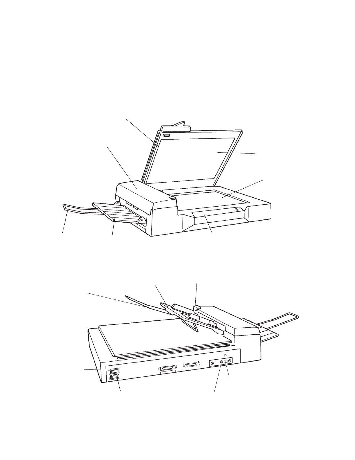
2.2.1 Exterior view of image scanner
The image scanner can read a document of A3 or double-letter size at
maximum.
Document cover
Automatic document
feeder (ADF)
Document
holding pad
Document
bed
Extension
Extension
Power switch
Stacker
Power inlet
ADF paper chute
Operator panel
ADF lever
10BASE-T interface connector
10BASE-2 interface connector
2–2
Figure 2.2 M3096NT parts names
Page 13

2.2.2 Functions of each part
Document cover: Closed over and holds a document to be
Document bed: A document to be read is placed on the
Document holding pad: Presses a document to the document bed.
Automatic document feeder (ADF):
Stacker: Stacks the read documents.
Extension: Keeps the stacked documents from
Power switch: Turns the power on or off.
Indication panel: The indication panel indicates the status
ADF paper chute: Holds the documents to be fed by the
read.
bed also called Flatbed (FB).
Automatically feeds documents to the
reading position.
overhanging.
of the scanner.
automatic document feeder.
ADF lever: Opens or closes the automatic document
feeder to remove documents jammed in
the feeder.
Power inlet: To be connected to an AC power outlet
with the power cable.
Interface connectors: To be connected to the host system with
interface cables.
2–3
Page 14
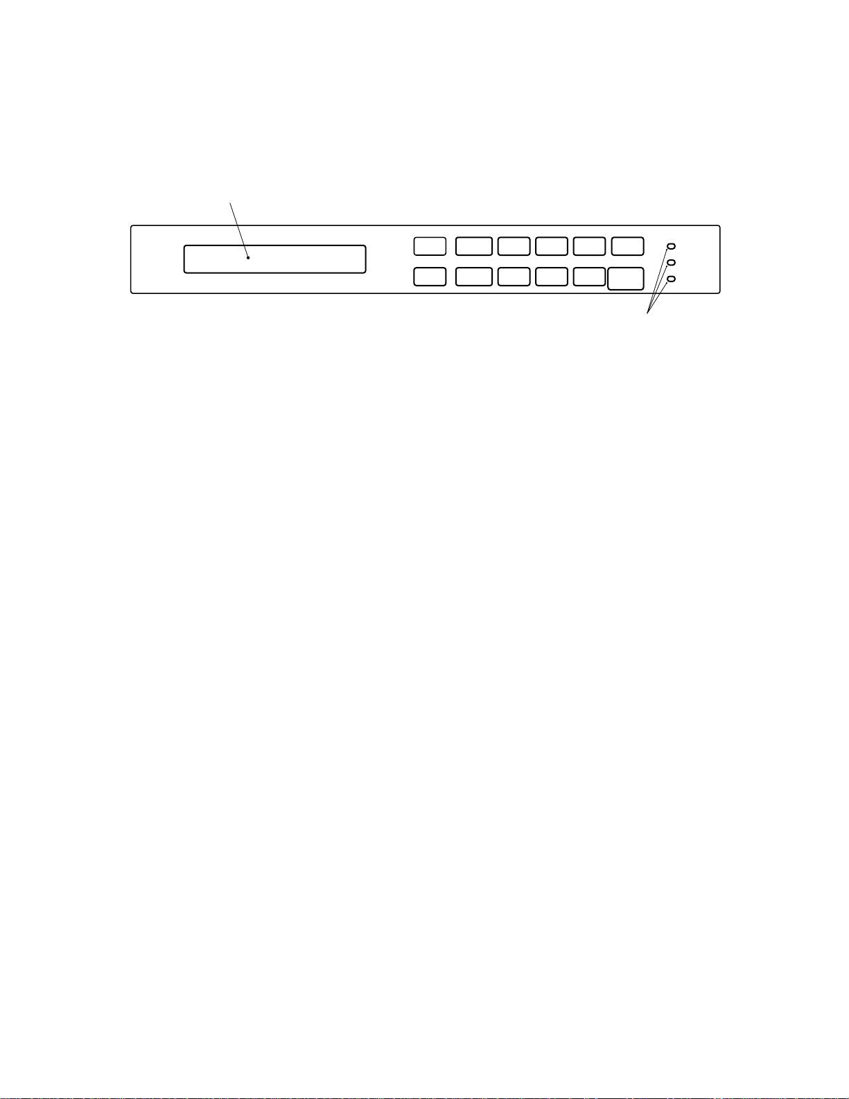
2.3 Operator Panel Functions
The operator panel has indicators and a liquid crystal display screen
for displaying image scanner status. The operator panel also has
operation buttons.
Liquid crystal display screen
2.3.1 Indicators
Buttons
1 3452
Mode 1
6 8907
Mode 2
Compression
ADF
Size
Landscape
Density
Halftone
Resolution
Document
Stop
Start
Figure 2.3 M3096NT operator panel
The meaning of each indicator is as follows:
Power indicator (Green):
Lights to indicate the power is on.
Read indicator (Green) :
In manual mode, when this lamp is lit, it indicates that the start
switch is enabled.
Power
Ready
Check
Indicators
Check (device check) indicator (Yellow):
Lights if a device error occurs which may result in a service
call. This indicator blinks if a document is jammed in the
automatic document feeder. This indicator turns off when the
jammed documents are removed from the feeder and the feeder
is closed.
2–4
Page 15

2.3.2 Buttons and liquid crystal display screen
The function of each button is as follows:
Start button:
Read operation can be started in either manual or automatic
mode. To start reading in manual mode, press this button while
the ready indicator is lit.
• Manual mode: Reading is started by the start button.
{
• Automatic mode: Reading is started by a command from
the host system.
Stop button:
This button is effective regardless of whether the scanner is in
manual or automatic mode. Press this button to stop the read
operation. When this button is pressed, the image scanner
operates as follows:
• Reading in flatbed mode: Reading is immediately stopped.
{
• Reading in ADF mode: Reading is immediately stopped
and documents being fed are ejected to the stacker.
After cleaning a jam, press the stop button to clear the
“Paper Jam” message displayed on the screen. The
ready screen will then be displayed to indicate that the
scanner is ready to read.
2–5
Page 16

This page is intentionally left blank.
2–6
Page 17

CHAPTER 3 INSTALLATION AND CONNECTIONS
3.1 Precautions
3.2 Removing the Carrier Fixing Bracket
3.3 Connections
3.4 Mounting the Stacker
3.5 Server Side Setup
3.6 Scanner Side Setup
3.7 Client Side Setup
3.8 Scan
This chapter explains how to install and connect the image scanner.
3.1 Precautions
Do not install the image scanner in the following places and environments. See the appendix A.1 “Installation Specifications” for the
information such as size of installation space.
Place the scanner away from electrical noise
sources and strong magnetic fields. If the
image scanner is used near an air conditioner,
copying machine, or TV set, the scanner may
operate incorrectly.
Keep the scanner out of the sun and away
from heaters. These environments may
shorten scanner life or cause hardware
failures.
Do not install the scanner in a place where
vibrations may occur. This environment may
cause hardware failures or may cause the
scanner to operate incorrectly.
CAUTION
Place the image scanner on a level surface.
Place the image scanner so that the rubber
pads are secured on a flat and solid desktop.
Do not install the scanner in a humid, dusty,
or damp places. These enviroments may
shorten scaner life or cause hardware failures. Do not place the image scanner where
liquid spills may occur. Place it on a flat and
even surface.
Be aware of static electricity. If static
electricity is generated, the scanner may
operate incorrectly. Be sure that the flooring
and the desk are made of materials that do
not generate static electricity.
3–1
Page 18
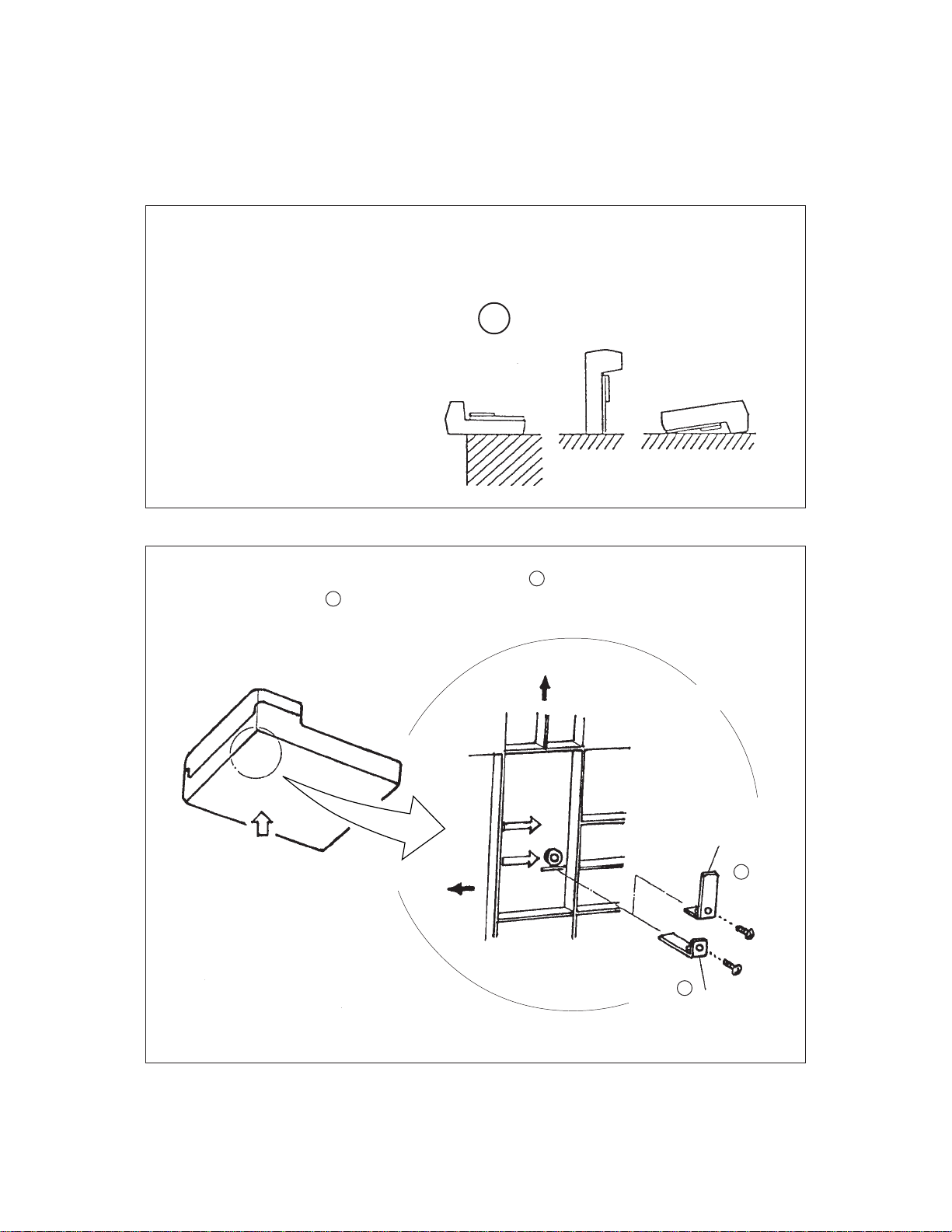
3.2 Removing the Carrier Fixing Bracket
To keep the scanner from being damaged during shipping, the carrier
unit is fixed with a bracket. After placing the carrier unit at the
installation place, remove this bracket as explained below.
1 Place the image scanner on the edge of the desk top so that the left side (where ADF
is placed) of the scanner extends from the desk top. Do not set the image scanner
upside down or on its side.
×
2 Remove the carrier fixing bracket from position A. Then install the carrier fixing
bracket at position B.
Front side
×
Enlarged
Bottom view
Carier bracket (Position for
storage, position for shipment)
Enlarged section A enlarged
3–2
Carier bracket
(Position for operation)
B
ADF side
A
Carier bracket
(Position for shipment)
Page 19
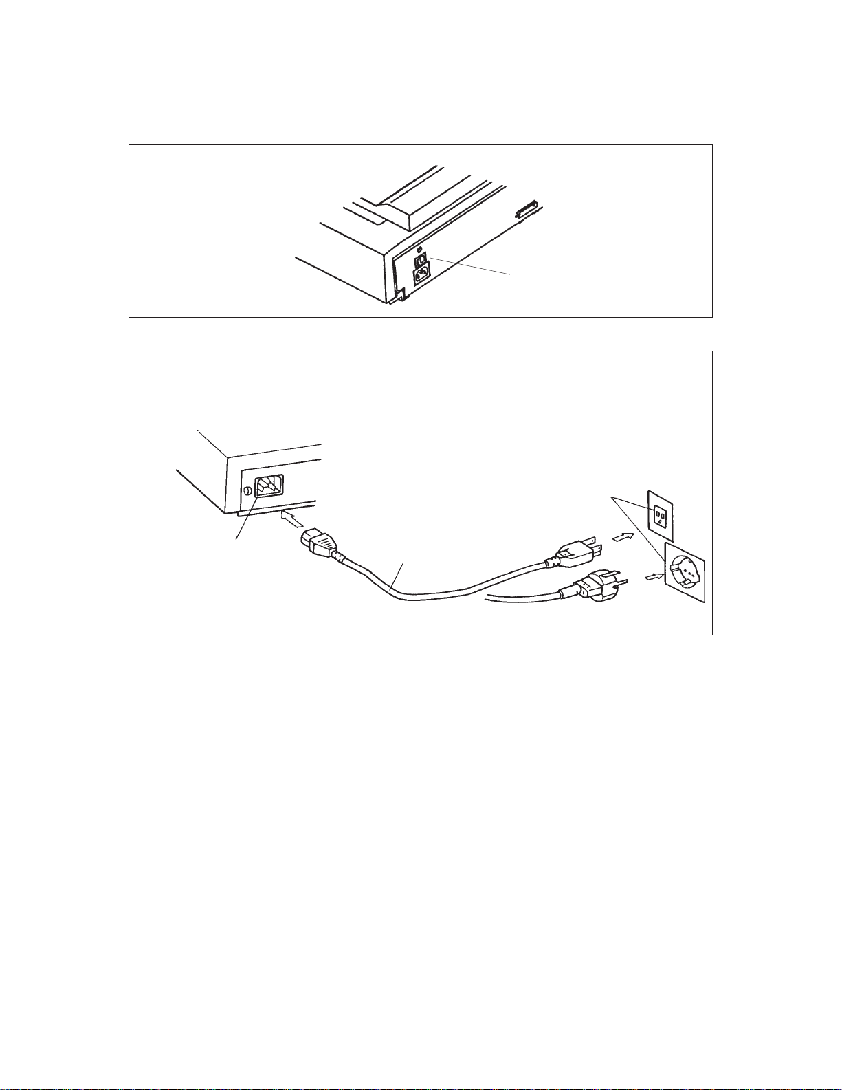
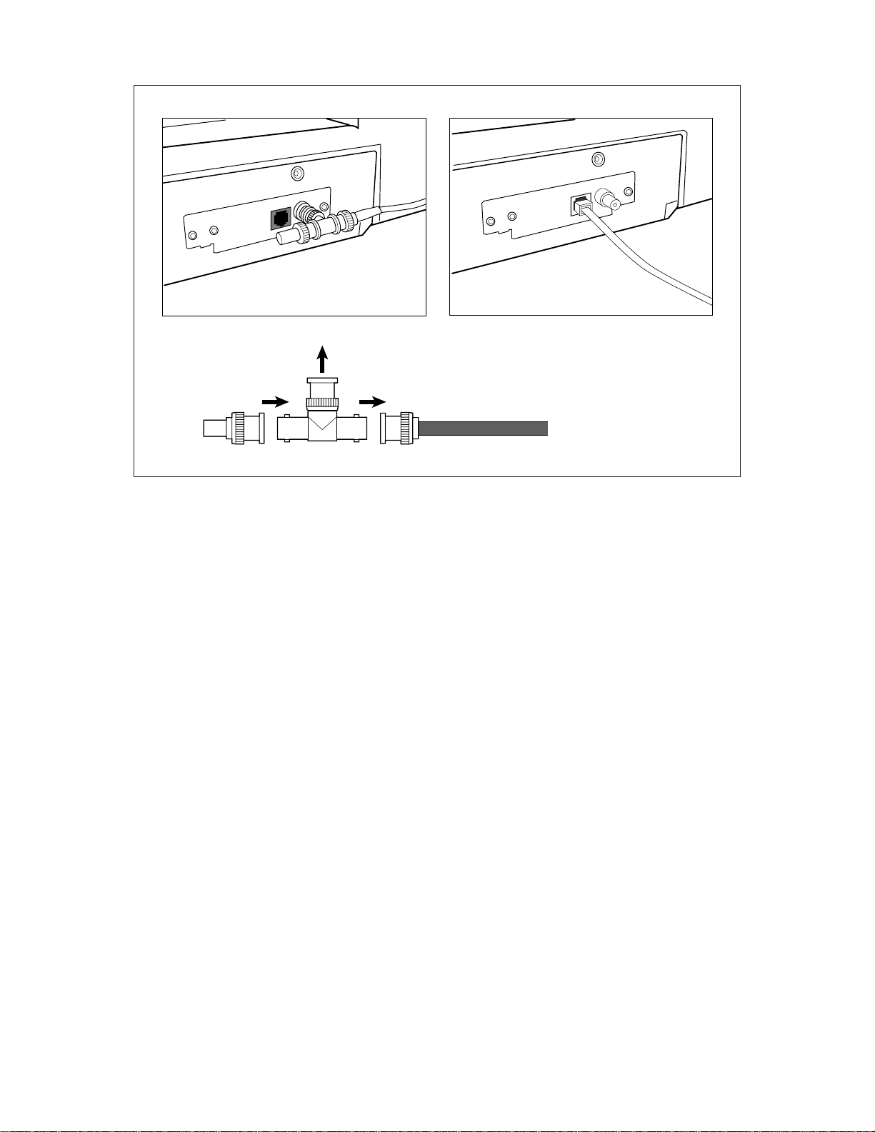
3.3 Connections
Connect the image scanner using the following procedure.
1 Set the power switch to off.
2 Connect the power cable.
Connect the power cable to the power inlet on the back of the image scanner.
Connect the other end of the power cable to a power outlet.
Power switch
Power inlet
Power outlet
for North America
Power cable
for Europe
3–3
Page 20
3
2
1
3–4
Page 21
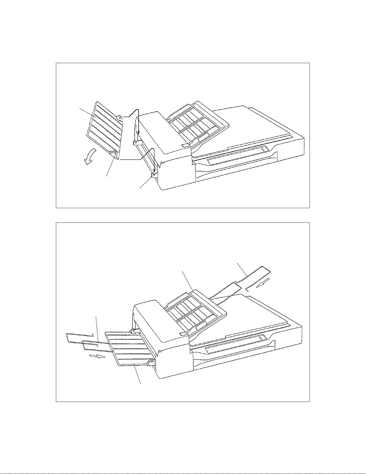
3.4 Mounting the Stacker
Mount the stacker and extensions using the following procedure.
1 Mount the stacker.
Hook the pins on the stacker to the claws on the image scanner.
Stacker
Pin
Claw
2 Mount the extensions.
Mount extensions to the stacker and to the ADF paper chute.
Extension
Extension
ADF paper chute
Stacker
3–5
Page 22
3.5 Server Side Setup
Setup Procedure Example : WindowsNT4.0
3.5.1 Login
Login to WindowsNT Server as “Administrator”.
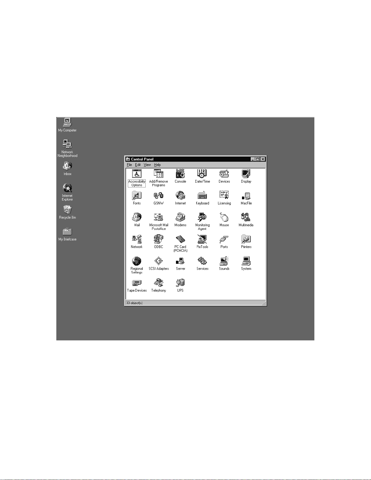
3.5.2 Open the “Control Panel” Folder
Select from Task Bar “Start” → ”Settings” → “Control Panel”
3–6
Page 23
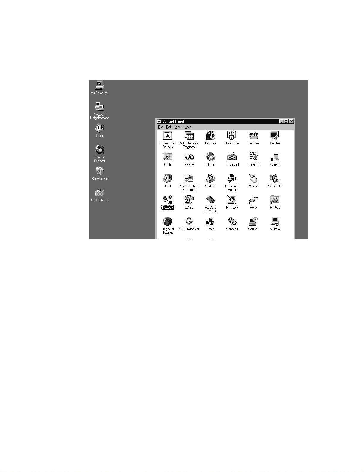
3.5.3 TCP/IP setup
3.5.3.1 TCP/IP setup – Run “Network”
Double Click ”Network” icon.
3–7
Page 24
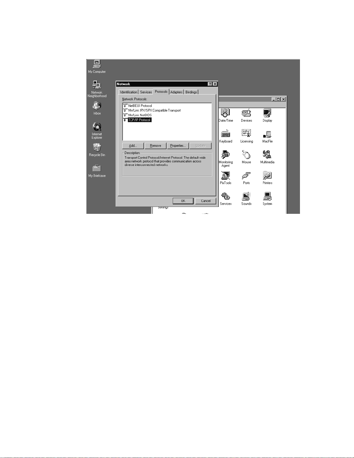
3.5.3.2 TCP/IP setup – Verify TCP/IP Protocol
Click “Protocols” TAB. Verify “TCP/IP Protocol” is listed
If “TCP/IP Protocol” is not listed, click Add BUTTON and Install
“TCP/IP Protocol”.
See Windows NT Operating System Manual for details.
After the TCP/IP Protocol Installation, you need to restart the Windows NT. Then try again from step 3.5.1.
3–8
Page 25
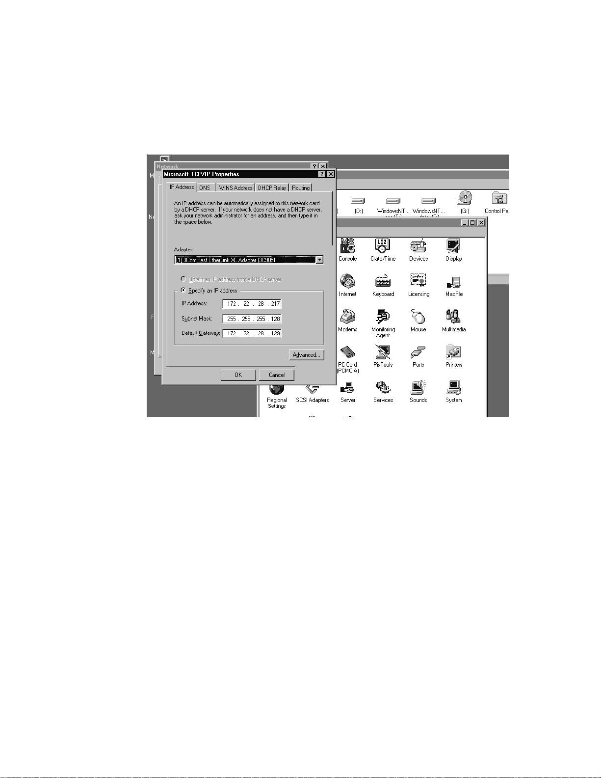
3.5.3.3 TCP/IP setup – Notes Required Information
Double Click “TCP/IP Protocol” and Click IP Address TAB.
Please notes following values. These are required for M3096NT setup.
IP Address
Subnet Mask
Default Gateway
Click “Cancel” BUTTON until Network DIALOG BOX.
If any of IP Address, Subnet Mask, Default Gatway is entered, Click
“OK” BUTTON and restart Operating System.
3–9
Page 26
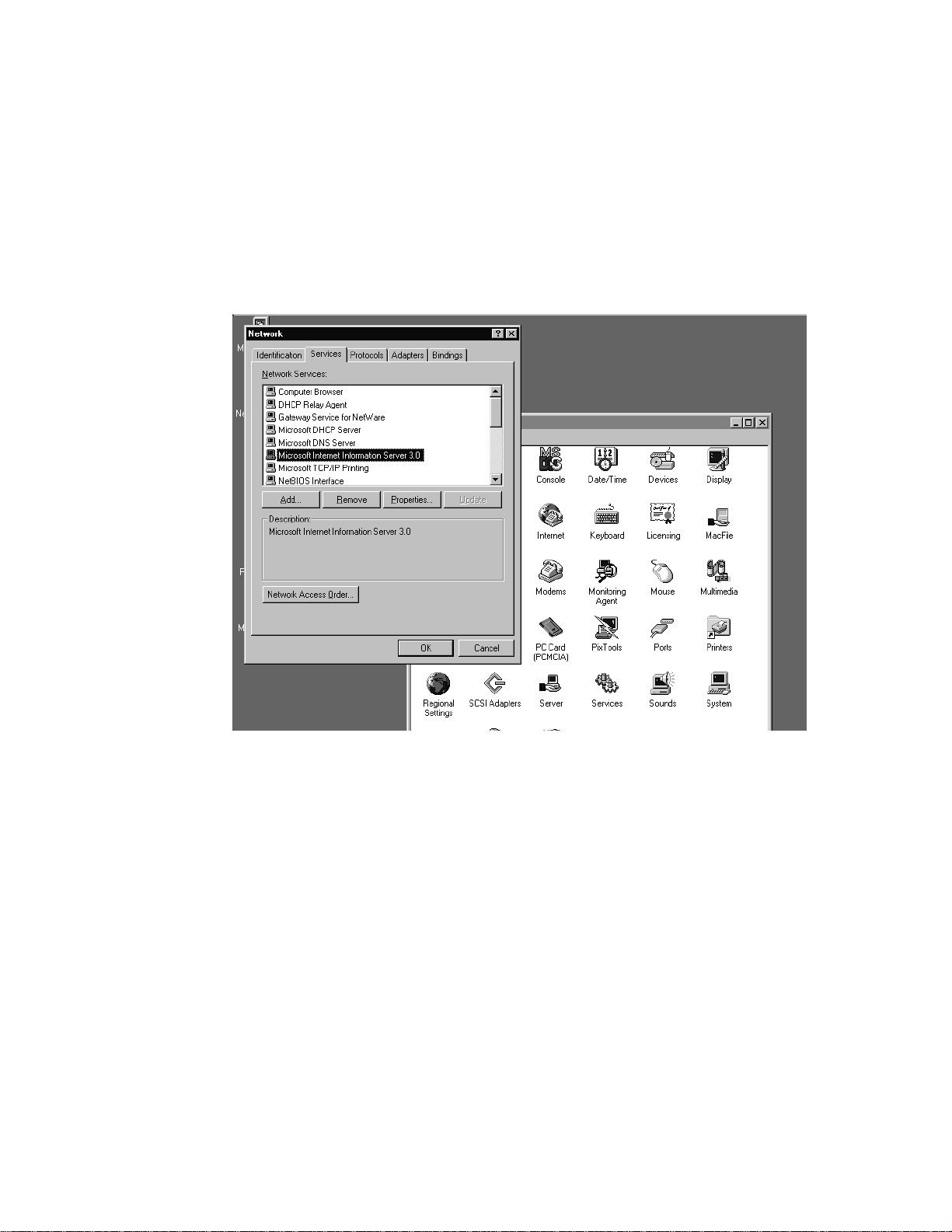
3.5.4 “Internet Information Server” setup
3.5.4.1 “Internet Information Server” setup – Verify Network Services
Click “Services” TAB from Network DIALOG BOX.
If “Microsoft Internet Information Server 2.0” or higher is not installed, click Add BUTTON and Install “Microsoft Internet Information Server”.
See Windows NT Operating System Manual for details.
3–10
If “Microsoft Internet Information Server” is already installed, Click
“Cancel” BUTTON and exit Network setup.
If “Microsoft Internet Information Server” needs to be Installed,
restart the Operating System and Login again.
Page 27
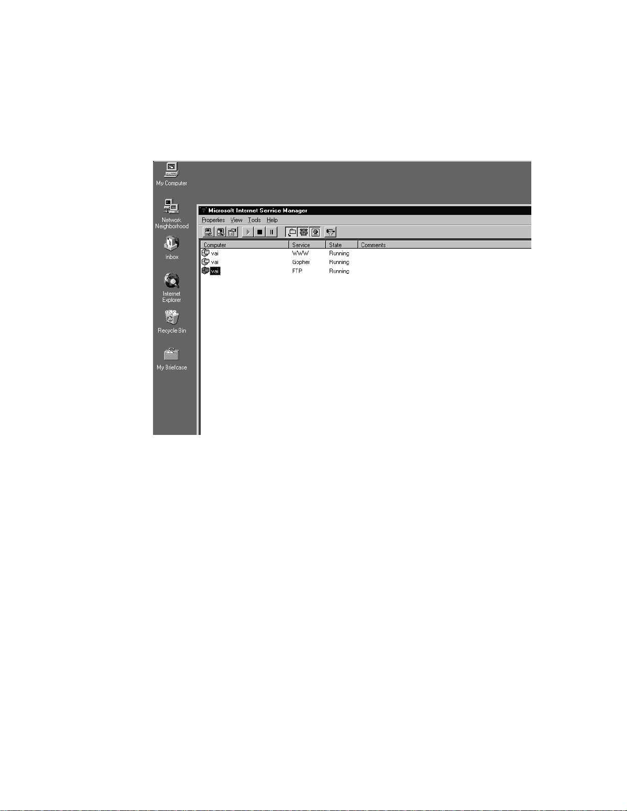
3.5.4.2 “Internet Information Server” Setup – Start Microsoft Internet Service Manager.
Select TaskBar “Start” → ”Program” → ”Microsoft Internet Information Server” → ”IIS Manager”.
If the window below is displayed, check FTP service State is “Running”.
Then Double Click Computer icon which servicing FTP.
3–11
Page 28
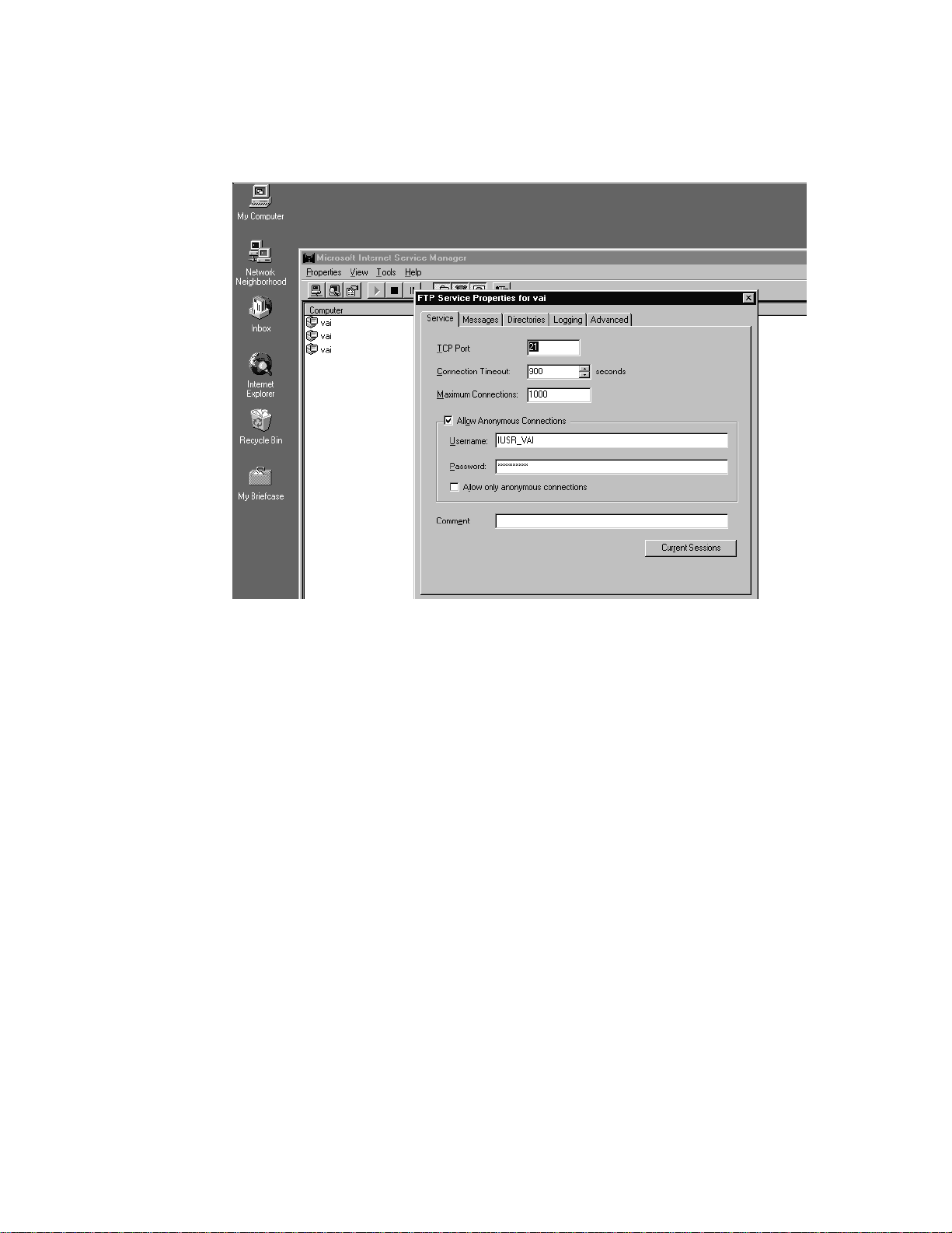
3.5.4.3 Setup “Internet Information Server” – Allow non-anonymous login
Click “Service” TAB.
Reset CHECH BOX “Allow only anonymous connections” as below
3–12
Page 29
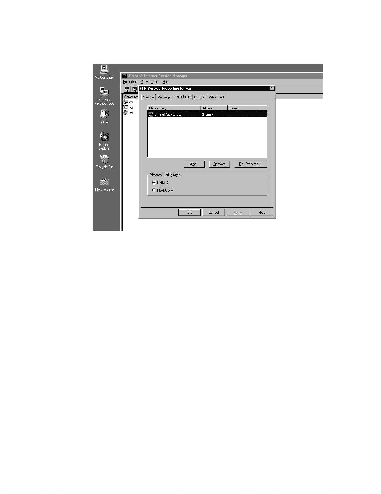
3.5.4.4 “Internet Information Server” setup – Set Home Directory
Click “Directory” TAB. Select “D:\InetPub\ftproot” Directory.
3–13
Page 30
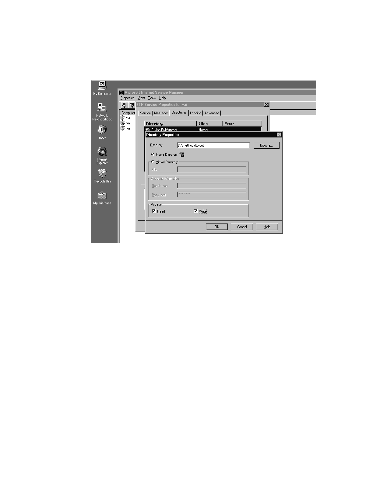
3.5.4.5 “Internet Information Server” setup – Set Directory Access Properties
Setup “Internet Information Server” - Click “Edit Properties” BUTTON
Set CHECK BOX “Read” and “Write”.
Click “OK” BUTTON and exit Microsoft Internet Service Manager”
3–14
Page 31

3.5.5 Create User
3.5.5.1 Create User – New User
Run User Manager as Select TaskBar “Start” → ”Program” → “Administrative Tools” → ”User Manager for Domain”.
Select User MENU → ”New User”
Input as follows
User Name “NWKSCAN”
Password “NWKSCAN1” (Displayed as ”*******”)
Confirm Password “NWKSCAN1” (Displayed as ”*******”)
Reset Check Box “User Must Change Password at Next
Logon”
Reset Check Box “User Cannot Change Password”
Set Check Box “Password Never Expires”
Click Add BUTTON to add new user and Click Cancel BUTTON to
exit New User DIALOG BOX.
3–15
Page 32

3.5.5.2 Create User – Set User Rights Policy (1)
Select Policies MENU → “User Rights” to open User Rights Policy
DIALOG BOX.
Select Right ITEM → “Logon Locally” and Click Add BUTTON.
3–16
Page 33

3.5.5.3 Create User – Set User Rights Policy(2)
Click Search BUTTON.
3–17
Page 34

3.5.5.4 Create User – Set User Rights Policy(3)
Input “NWKSCAN” in Find or Groups EDIT BOX and Click Search
BUTTON.
If user “NWKSCAN” is displayed at Search Results, click Add
BUTTON.
If user “NWKSCAN” is not displayed at Search Results, Click Cancel
BUTTON and retry from 3.5.5 Create User.
3–18
Page 35

3.5.5.5 Create User – Set User Rights Policy(4)
Verify the “NWKSCAN” is displayed at Grant To LIST, Click OK
and exit User Manager.
3–19
Page 36

3.5.6 Create NWKSCAN Home Directory
3.5.6.1 Create NWKSCAN Home Directory - Create Directory
Run Explorer as Select TaskBar “Start” → “Program” →
“WindowsNT Explorer”.
Create Directory NWKSCAN, under “\InetPub\ftproot”.
3–20
Page 37

3.5.6.2 Create NWKSCAN Home Directory – Sharing Directory
Select NWKSCAN directory and Select “File” MENU → “Sharing”
to open NwkScan Properties DIALOG BOX.
Set Shared As ITEM as below and close DIALOG BOX.
3–21
Page 38

3.5.7 Administration Program Installation
3.5.7.1 Install M3096NT Scanner Suite(1)
Insert “Fujitsu M3096NT Scanner Suite” floppy disk.
Open Control Panel as 3.5.2. Double Click Add/Remove Program
icon.
3–22
Page 39

3.5.7.2 Install M3096NT Scanner Suite(2)
Double Click Install BUTTON.
3–23
Page 40

3.5.7.3 Install M3096NT Scanner Suite(3)
Click Next BUTTON.
3–24
Page 41

3.5.7.4 Install M3096NT Scanner Suite(4)
The Installation Program Search Floppy disk and shows
“A:\SETUP.EXE” as below.
Then Click Finish BUTTON.
3–25
Page 42

3.5.7.5 Install M3096NT Scanner Suite(5)
Fujitsu M3096NT Scanner Suite installation runs from floppy disk.
Click Next BUTTON.
3–26
Page 43

3.5.7.6 Install M3096NT Scanner Suite(6)
On Line Software License Agreement is displayed. If you agreed to
this license Click Yes BUTTON.
3–27
Page 44

3.5.7.7 Install M3096NT Scanner Suite(7)
Input your Name and Company and Click Next BUTTON.
3–28
Page 45

3.5.7.8 Install M3096NT Scanner Suite(8)
Destination Directory is displayed as “M3096NT”.
In this installation example, directory has to be changed to
“\InetPub\ftproot\NWKSCAN”.
Click Browse BUTTON.
3–29
Page 46

3.5.7.9 Install M3096NT Scanner Suite(9)
Select “\InetPub\ftproot\NWKSCAN” of Directory.
Click OK BUTTON and Click Next BUTTON.
3–30
Page 47

3.5.7.10 Install M3096NT Scanner Suite(10)
Select Administrator and Click Next BUTTON.
3–31
Page 48

3.5.7.11 Install M3096NT Scanner Suite(11)
If you are in United States or using 8.5x11 inch Size Paper, Select
U.S.A. Installation.
If you are in other than United States or using A4 Size Paper, Select
non-U.S.A. Installation.
CAUTION: This does not change languages.
3–32
Page 49

3.5.7.12 Install M3096NT Scanner Suite(12)
Click Next BUTTON.
3–33
Page 50

3.5.7.13 Install M3096NT Scanner Suite(13)
Click Next BUTTON.
3–34
Page 51

3.5.7.14 Install M3096NT Scanner Suite(14)
Click Finish BUTTON.
3–35
Page 52

3.5.7.15 Install M3096NT Scanner Suite(15)
Following Icons are Installed then Installation was successful.
3–36
Page 53

3.5.8 Administration Software
3.5.8.1 Scanner Configuration (1)
Double Click “Fujitsu M3096NT Administrator” Icon to run Administration Software.
If the Current Login directory is different, push “Change Login
Directory” BUTTON and specify correct directry. (In this example,
“\inetpub\ftproot\nwkscan”).
3–37
Page 54

3.5.8.2 Administration Software(2)
Click “Edit Scanner Configuration” BUTTON and open window as
below.
If this is the first M3096NT installation, you can utilized pre-setting
scanner ID “00”.
Push “Edit” BUTTON to configure the scanner.
3–38
Page 55

3.5.8.3 Administration Software(3)
Scanner Name is your Scanner Name which corresponding to Scanner
ID.
Description is explanation of the scanner.
Click Edit Scanner Configuration BUTTON to open the “Edit Scanner
Configuration” DIALOG BOX as below.
3–39
Page 56

3.5.8.4 Administration Software(4)
Set required values and Click OK BUTTON.
Definition of each ITEM are referenced by Help File, Click Help
BUTTON.
• Overwrite ITEM specifies ON/OFF is file overwrite by scanner
when same name file is existed.
• Network Timeout ITEM specifies time limits of M3096NT Network
communication. When network traffic is heavy, set time to longer.
• Inactivity Timeout ITEM specifies Time Limits. There’s no operation for this period, image scanner quit logon session automatically.
• Logging ITEM specifies enable/disable scanning logging.
• Name Display ITEM specifies to display or not display username on
operator panel when User ID is entered.
• User ID Required ITEM specifies enable/disable login by User ID.
When this Item is ON(default), Scan Setting/Image Directory are
identified by User ID. When this Item is OFF, user’s login is not
required and Scan Setting/Image Directory are common for all user.
3–40
Page 57

3.5.8.5 Administration Software(5)
Click “Edit Scan Parameters” BUTTON to open the “Edit Scan
Parameters” DIALOG BOX.
3–41
Page 58

3.5.8.6 Administration Software(6)
The DEFAULT.PRM file is displayed on List of PRM files.
Click Edit BUTTON to adjust default Scanning Setting.
Click Add BUTTON to create New Scanning Setting.
3–42
Page 59

3.5.8.7 Administration Software(7)
Set required values and Click Advanced BUTTON.
Definition of each ITEM are referenced by Help File, Click Help
BUTTON.
Image Directory should be changed to NWKSCAN\SCAN##(”##” is
Scanner ID).
3–43
Page 60

3.5.8.8 Administration Software(8)
Set required values and Click OK BUTTON. (Skip 3.5.8.9.)
Definition of each ITEM are referenced by Help File, Click Help
BUTTON.
If IPC-3 Image Processing option is installed in your M3096NT, Push
Edit IPC files BUTTON to Edit IPC files.
3–44
Page 61

3.5.8.9 Administration Software(9)
Set required values and Click OK BUTTON.
Definition of each ITEM are referenced by Help File, Click Help
BUTTON.
3–45
Page 62

3.5.8.10 User Configuration (1)
Click “Edit User Configuration” BUTTON and open window as
below.
The User ID “00” is registered as default.
Click “Edit” BUTTON to configure the user scanning setting.
Click “Add New” BUTTON to create and configure new user scanning setting.
The following description is example of creating new user.
3–46
Page 63

3.5.8.11 User Configuration (2)
• User ID is 8 digits or less decimal number which corresponds to
user setting. The Telephone extension or Company ID code, can be
used for this ID.
• User Name is 24 or less Alphabet/Numeric characters. The User
Name is displayed on LCD panel of the scanner when USER ID is
entered.
• Description is 40 or less Alphabet/Numeric characters.
• Directory is default of user. The user unique information like as
Scanning Parameters or Image Data, etc., are stored in this directory.
If above items are filled up. Click “Edit Scan parameters” BUTTON
to edit scanning parameter.
3–47
Page 64

The following Two message may display. These are Normal. Click
“OK” BUTTON.
3–48
Page 65

3.5.8.12 User Configuration (3)
The DEFAULT.PRM file is created under
“NWKSCAN\USERS\4395(UserID)” directory. This file is default
scanning parameter file for each user. By editing this file, Scanning
Parameter is customized for each user.
Click Edit BUTTON to edit DEFAULT.PRM.
Click Add New BUTTON to create another scanning parameter file.
Select PRM file and Push Change BUTTON is change default prm
file to another. Other than DEFAULT.PRM file can be a default file
with this BUTTON.
3–49
Page 66

3.5.8.13 User Configuration (4)
Set required values and Click OK BUTTON.
Definition of each ITEM are referenced by Help File, Click Help
BUTTON.
3–50
Page 67

3.5.8.14 User Configuration (5)
Set required values and Click OK BUTTON.
Definition of each ITEM are referenced by Help File, Click Help
BUTTON.
3–51
Page 68

3.5.8.15 Firmware
Insert “M3096NT Firmware” Floppy disk.
Drag and Drop, ‘A:\96NT####.fwu’ (‘####’ indicates firmware
revision number) file to ‘\InetPub\ftproot\NWKSCAN\Firmware’
directory.
This ‘96NT####.fwu’ file is downloaded by M3096NT Off-Line
mode-Firmware Update operation.
3–52
Page 69

3.6. Scanner Side Setup
The scanner side setup is assuming that M3096NT is physically setup
on Network.
Before starting, please check followings.
1. Carrier Unit fixing bracket is removed and located to operating
2. Power Cable is connected.
3. Stet Network (10BASE-2 or 10BASE-T) cable is Connected.
position.
10BASE-T
10BASE2
3–53
Page 70

3.6.1 Power-On Off-Line Mode
As factory default, M3096NT startup in Off-Line mode as below,
when at first Power-On.
Off-Line Mode
Save=Start Cancel=Stop
Until Off-Line mode scanner configuration is finished, M3096NT
does not start On-Line mode. M3096NT Off-Line mode functions,
however, required setting to start up is 6.
Button Submenus
Mode1/1 Local IP Address Setting
ADF/2 Server IP Address Setting
Size/3 Subnet Mask Setting
Density/4 Gateway IP Address Setting
Mode2/6 LAN Connector Type Setting
Compression/7 Scanner ID Setting
1
Mode 1
67
Mode 2
2
ADF
Compressi on
Landscape
453
Stop
Start
98
Resolution
0
DocumentHalftone
DensitySize
3–54
Page 71

3.6.2 Local IP Address
Press Mode1/1 button to start Local IP Address input screen.
Off-Line Mode
Save=Start Cancel=Stop
LCD panel message is changed as below. Input M3096NT IP address.
Local IP Address
xxx.xxx.xxx.xxx
Ex.
If M3096NT IP Address is “172.22.28.219” then Press button as
below.
1
Mode 1
7
Compresion
1
Mode 1
67
Mode 2
2
ADF
022
Document ADF ADF
2
ADF
Compressi on
453
DensitySize
98
Landscape
Resolution
0
DocumentHalftone
Stop
Start
219
ADF Mode1 Halftone
Press “Start” button to initial screen, at last. If you made mistake to
input, press “Stop” button. The bottun operates as Back Space.
3–55
Page 72

3.6.3 Server IP Address
Press ADF/2 button to start Server IP Address input screen.
Off-Line Mode
Save=Start Cancel=Stop
LCD panel message is changed as below. Input WindowsNT Server
IP address which is recorded in 1.3.3. TCP/IP setup.
Server IP Address
xxx.xxx.xxx.xxx
Ex.
If Server IP Address is “172.22.28.215” then Press button as below.
1
Mode 1
7
Compresion
1
Mode 1
67
Mode 2
2
ADF
022
Document ADF ADF
2
ADF
Compressi on
453
DensitySize
98
Landscape
Resolution
0
DocumentHalftone
Stop
Start
215
ADF Mode1
Resolution
Press “Start” button to initial screen, at last. If you made mistake to
input, press “Stop” button. The bottun operates as Back Space.
3–56
Page 73

3.6.4 Subnet Mask
Press Size/3 button to start Subnet Mask input screen.
Off-Line Mode
Save=Start Cancel=Stop
LCD panel message is changed as below. Input Subnet Mask which is
recorded in 3.5.3.3. TCP/IP setup.
Subnet Mask
xxx.xxx.xxx.xxx
Ex.
If Server IP Address is “255.255.255.128” then Press button as below.
2
ADF
5
Resolution Resolution
1
Mode 1
67
Mode 2
5
255
ADF
2
ADF
Compressi on
Resolution Resolution
Landscape
453
DensitySize
98
Resolution
DocumentHalftone
Stop
0
Start
128
Mode 1 ADF
Landscape
Press “Start” button to initial screen, at last. If you made mistake to
input, press “Stop” button. The bottun operates as Back Space.
3–57
Page 74

3.6.5 Gateway IP Address
Press Density/4 button to start Gateway IP Address input screen.
Off-Line Mode
Save=Start Cancel=Stop
LCD panel message is changed as below. Input Gateway IP Address
which is recorded in 3.5.3.3. TCP/IP setup.
Gateway IP Address
xxx.xxx.xxx.xxx
Ex.
If Server IP Address is “172.22.28.129” then Press button as below.
1
Mode 1
7
Compresion
1
Mode 1
67
Mode 2
2
ADF
022
Document ADF ADF
2
ADF
Compressi on
453
DensitySize
98
Landscape
129
Mode 1 ADF Halftone
Resolution
0
DocumentHalftone
Stop
Start
Press “Start” button to initial screen, at last. If you made mistake to
input, press “Stop” button. The bottun operates as Back Space.
3–58
Page 75

3.6.6 LAN Connector
Press Mode2/6 button to start LAN Connector input screen.
Off-Line Mode
Save=Start Cancel=Stop
1
Mode 1
67
Mode 2
2
ADF
Compressi on
Landscape
453
98
Resolution
0
DocumentHalftone
DensitySize
LCD panel message is changed as below. Specify the LAN Connector.
LAN Connector Type
x Not Specified
If LAN Connector is not sure then Press Mode2/6 button once to
select ”Auto”.
If LAN Connector is ”10BASE-T” then Press Mode2/6 button 2time.
If LAN Connector is ”10BASE2” then Press Mode2/6 button 3time.
6
Mode2
6
Mode2
Auto
10BASE-T
Stop
Start
6
Mode2
10BASE2
Press “Start” button to initial screen, at last. If you made mistake to
input, press “Stop” button. The bottun operates as Back Space.
3–59
Page 76

3.6.7 Scanner ID
Press Compression/7 button to start Scanner ID input screen.
Off-Line Mode
Save=Start Cancel=Stop
LCD panel message is changed as below. Input Scanner ID.
Enter Scanner ID
Ex.
If Server IP Address is “00” then Press button as below.
Document0Document
Press “Start” button to initial screen, at last. If you made mistake to
input, press “Stop” button. The bottun operates as Back Space.
0
1
Mode 1
67
Mode 2
2
ADF
Compressi on
Landscape
xx
453
Stop
Start
98
Resolution
0
DocumentHalftone
DensitySize
3–60
Page 77

3.6.8 Save Parameters
Press Start button to save parameters.
Off-Line Mode
Save=Start Cancel=Stop
After saving the parameters, scanner will reboot. If setting is correct,
Scanner will display On-Line/Off-Line mode selection screen. Press
Start button or about 30sec. passed, scanner will start On-Line mode
automatically.
1
Mode 1
67
Mode 2
2
ADF
Compressi on
Landscape
453
Stop
Start
98
Resolution
0
DocumentHalftone
DensitySize
3–61
Page 78

3.7 Client Side Setup
3.7.1 Administration Program Installation
Client Side Setup is almost same to 3.5.7 Administration Program
Installation.
Insert “Fujitsu M3096NT Scanner Suite” floppy disk on client PC.
and follow the same procedure.
The difference is below.
1. Sec.3.5.7.8 “Destination Directory” is not need to change.
Sec.3.5.7.9 can be skipped.
2. Sec.3.5.7.10 Select “User”.
3–62
Page 79

3.7.2 Map “NWKSCAN” directory to network drive
3.7.2.1 Map “NWKSCAN” directory to network drive – Run Explorer
Run Explorer as Select TaskBar “Start” → ”Program” → ”Explorer”
or “WindowsNT Explorer”
Select your server from “Network Neightbourhood”.
In this case, the Server ‘Vai’ is found same WindowsNT Domain. If
your server is not in the same Domain, Click “Entire Network” and
search your Domain and server.
3–63
Page 80

3.7.2.2 Map “NWKSCAN” directory to network drive – Select “NWKSCAN” directory
Click Server ‘Vai’ icon, and select “NWKSCAN” directory.
3–64
Page 81

3.7.2.3 Map “NWKSCAN” directory to network drive – Map “NWKSCAN” directory
Select “File” MENU → ”Map Network Drive…”
Select Drive Letter( in this case, map to drive “S:”) and Click “OK”
BUTTON.
If you check “Reconnect at Logon” as below, you don’ need to follow
this step.
Map “NWKSCAN” Directory to network drive is finished.
3–65
Page 82

3.7.3 How to run Client Side Program
3.7.3.1 User Configuration(1)
To Run “Fujitsu M3096NT User Configuration”, Select TaskBar
“Start” → ”Program” → ”Fujitsu M3096NT Scanner Suite” →
”Fujitsu M3096NT User Configuration”.
Click “Login Directory” BURTTON.
3–66
Page 83

3.7.3.2 User Configuration (2)
Select “NWKSCAN” directory which is mapped as drive “S:\” as
Login Directory.
Click “OK” BUTTON.
3–67
Page 84

3.7.3.3 User Configuration (3)
Click “Edit” BUTTON to edit Scanning Parameter.
Click “Add New” BUTTON to create and edit new Scanning Parameter file.
Click “Delete” BUTTON to delete Scanning Parameter file.
Click “Change” BUTTON to specify user’s default scanning parameter file.
3–68
Page 85

3.7.4.1 Image Viewer(1)
To Run “Fujitsu M3096NT Image Viewer”, Select TaskBar “Start” →
”Program” → ”Fujitsu M3096NT Scanner Suite” → ”Fujitsu
M3096NT Image Viewer”.
Click “Login Directory” BUTTON.
3–69
Page 86

3.7.4.2 Image Viewer (2)
Select “NWKSCAN” directory which is mapped as drive “S:\” as
Login Directory.
Click “OK” BUTTON.
3–70
Page 87

3.7.4.3 Image Viewer (3)
Click “View” BUTTON to view scanned TIFF file.
Click “Refresh” BUTTON to refresh files in folder.
Click “Delete” BUTTON to delete TIFF file.
Click “Exit” BUTTON to exit Image Viewer.
In this time, TIFF file are not listed.
3–71
Page 88

3.8 Scan
The M3096NT Installation is completed.
Enter your User ID from M3096NT Network Scanner operator panel
and Press ‘Start’.
Then your default scanning parameter “DEFAULT.PRM” is loaded.
You can still change scanning parameter ScanPath (ADF, FB), Paper
Size (A5, A4, A3, B5, B4, 8.5x11, 8.5x14, 11x17), Density (BRT4,
BRT3, BRT2, BRT1, NORM, DRK1, DRK2, DRK3), Resolution
(200, 240, 300, 400), Compression(None, MH, MR, MMR, JBIG),
from operator panel.
If you want load another Scanning Parameter Press “Mode1” BUTTON
If you want load another IPC(Image Processing File) file, Press
“Mode2” BUTTON.
Put the document and “Start” BUTTON to Scan. Then TIFF file is
created under user directory. The TIFF file can open by M3096NT
Image Viewer as below.
3–72
Page 89

CHAPTER 4 OPERATOR PANEL SPECIFICATION
4.1 General
4.2 Initial Mode
4.3 On-Line Mode
4.4 Off-Line Mode
4.5 Messages
4.1 General
4.1.1 Introduction
This documentation describes about M3096NT Network Scanner
Operator Panel specification. This Operator Panel specification
consists of 3 modes(Initial mode/On Line mode/Off Line mode).
Initial Mode mainly displays the message of scanner start up status. If
any error message is displayed in this mode, it is hardware error.
On-Line mode indicates the network scanner is operating on network
environment by logging on to File Server. These modes are selected in
Off-Line mode.
Off-Line mode indicates the network scanner does not require File
Server in its operation except for firmware downloading.
4.1.2 Operator Panel Over View
Below shows the Operator Panel Outer View. It is consists of 24
column by 2 row LCD display and 12 buttons, 3 LEDs(not figured).
Each button has assigned functions as printed on the button. The 10 of
12 buttons are also assigned second function to input numbers as
printed above the buttons.
1
Mode 1
67
Mode 2
2
ADF
Compressi on
Landscape
453
Stop
Start
98
Resolution
0
DocumentHalftone
DensitySize
4–1
Page 90

4.1.3 General Sequence
e
o
o
e
INITIAL OFF LINE
ON LINE
Stop
Illegal ID
Stop
Power-On
M3096EX Initialize
PM3400 Initialize
Start
Login Ser ver
1 2 3 4 5
6 7 8 9 0
Start
Edit Scan Setting
Start
Stop
Start Stop
ADF
Size
WindowsNT Setup
Start
Remote Sca nne r modeUser ID I nput
Start
Can cel
Remote Scan
Select ADF/FB
Select Size
Stop
Save
Start
Scan
Stop
Continue S can?
Start
In ac t iv it y T ime o u t
or
Continue S es s i on?
In ac t iv it y T ime o u t
or
Scan Complete
Stop
Stop
Density
Resoluti
Compressi
Landscap
Document
Halfton
Mode 1
Mode 2
Start
Select
Select Density
Select Resolution
Select Compression
Select Orientation
Select Text/Photo
Select Halftone
Sub Menu
SelectParameterFile
Select IPC File
: Normal Flow
: Push Button
: enter sub-menu
Set
Start
Stop
Cancel
4–2
Page 91

4.2 Initial Mode
4.2.1 Power-On to Ready
After Power-On, the message below is displayed on LCD panel. This
message means the image scanner engine is warming up. If any error
message is displayed on the LCD at this time, the error may related to
image scanner engine (Lamp Failure, Carrier Locked, etc.)
Warming-up Now!!
All image scanner selftest/initialize sequence is completed, the screen
below is displayed.
ADF DL 400 L.>
4.2.2 Network Controller Initialization
Following to image scanner selftest/initialize sequence completion,
Network Controller starts Selftest/Initialize sequence. While Network
Controller Selftest/Initialize sequence, the message below is
displayed.
M3096NT Selftest
In P rog ress
All Network Controller selftest/initialize sequence is completed, the
message below is displayed
M 3096NT Selftest OK
V e rs ion : 01 .00
After all selftest/initialize sequence is completed, , the message below
is displayed.
On-Line Mode=Start
Off-L ine Mode=Stop
The above message is displayed for Inactivity Timeout period. While
this message is displayed, by pressing Start button to start the Login
procedure. By pressing Stop button, enters Off-Line Mode.
See Section 4.4 for details of Off-Line Mode.
4–3
Page 92

4.2.3 On-Line mode Start up
At the start up of On-Line mode, the Network Controller tries to login
to default File Server which has already specified in Off-Line mode
and downloading configuration file for user operation.
4–4
Page 93

4.3 On-Line Mode
4.3.1 User ID Input
In On-Line mode, the network scanner displays the message to enter
User ID. The M096NT identifies the user name and file directory that
image data is stored.
The User ID has to be registered in File Server by Administration
Software, in advance.
To input user ID, second function of operator panel button is used. For
example, to enter ‘1’ push Mode1 button, to enter ‘2’ push ADF
button. So other than ‘Start’, ‘Stop’ buttons are used to enter number
as second function.
Enter User ID
00
21
Mode 1
67
ADF
Compression
453
ResolutionDensitySize
908
DocumentHalftoneLandscapeMode 2
Stop
Start
Second Function Buttons
By Pressing Start button after entering the User ID, scanner tries to
identify User ID.
By Pressing Stop button or User ID is illegal, scanner cancel the
entered User ID and return to Enter User ID prompt.
By pressing Start button before entering any number, the scanner
enters Remote Scanner Mode. In this mode, scanner can login to other
file server. See 4.3.1.1 Remote Scanner Mode.
See 4.4.3 Server IP Address Setting for how to set IP Address.
After the selection of server and by pressing Start button, the scanner
starts login process as described in 2.3 On-Line mode Start up.
If this process is completed, operation is identical and continued for
User ID input. But Temporary login is valid for one scanning.
Scanning has finished, scanner automatically logoff from temporary
server.
If temporary login is failed, by pressing Stop button, cancel the
process. This is the difference to default login.
4–5
Page 94

4.3.1.1 Remote Scanner Mode
Remote Scanner Mode is supported to permit temporary login to
another File Server. The File Server has to be configured by
Administration Software for M3096NT to Login..
At the “Enter User ID” screen, by pressing Start button before
entering User ID numbers, Remote Scanner Mode is invoked and the
message below is displayed.
Cont=Start Cancel=Stop
By pressing Start button, enter the Remote Scanner Mode.
By pressing Stop button, quit the Remote Scanner Mode and return to
User ID input screen.
Enter IP address of the Alternate File Server.
Server IP Address
A lterna te Server?
xx.Xxx .xxx.xxx
See 4.2 Server IP Address Setting for how to input IP Address.
By pressing Stop button, quit the Remote Scanner Mode and return to
User ID input screen.
Alternate Server is correctly specified in above procedure, the network
scanner searches for the alternate File Server and try to Login.
If the Login is successful, same screen to 3.1 User ID Input is
displayed. After then procedure is same.In this time, it is still possible
to invoke Remote Server mode but it is not nested. How many times
Remote Scanner is invoked, after the scanning returned to default File
Server.
If the login is unsuccessful, error message is displayed and return to
User ID input screen.
4–6
Page 95

4.3.2 Scan Parameter Setting/Scanning
After User ID input, the scanner shows the Scan Parameter settings as
below.
ADF 8.5x11 Norm 400dpi
MMR Port HT1 Text
10
Mode 1
56
ADF
Compression
342
897
DocumentHalftoneLandscapeMode 2
The default Scan Parameter is displayed which is specified in default
.PRM file.
In this screen, Scan Parameter can be edited. To edit Scan Parameters
Setting, press the corresponding button to function as below. See
details for each chapter.
Button Chap. Description (‘*’ asterisk indicates default)
ADF 4.3.2.1 Select scan path *ADF/Flatbed
Size 4.3.2.2 Select Document Size A5/*A4/A3/B5/B4/8.5x11/8.5x14/11x17
Brightness 4.3.2.3 Select Brightness in 8 steps
Resolution 4.3.2.4 Select Resolution 200/240/300/400dpi
Compression 4.3.2.5 Select Compression Algorithm JBIG/*MMR/MR/MH/None
Landscape 4.3.2.6 Select Page Orientation *Portrait/Landscape
Halftone 4.3.2.7 Select Halftone Pattern *HT1/HT2/HT3/HT4/Error Diffusion
Document 4.3.2.8 Select Document Type *Text/Photo
Mode 1 4.3.2.9 Select Scan Parameter File
Mode 2 4.3.2.10 Select Image Processing Circuit File
StopResolutionDensitySize
Start
Scan Parameter File can include all the Scan Parameter even in IPC
function. Therefore, it is enough to select the .PRM file by pressing
Mode1 button in most case.
The IPC file parameter cannot be edited from operator panel.
4–7
Page 96

By pressing Start button, Scanner starts scanning with specified
parameters.
If ADF mode is selected, documents on ADF are scanned until empty
or Stop button is pressed.
If FB mode is selected, document on Flatbed is scanned.
While scanning, the message as below is displayed.
Scanning...
While storing, the message as below is displayed.
Storing IM 000000.TM P
page 1
After scanning, the message as below is displayed to ask continue or
not.
Continue Document?
Yes=Start No=StoP
By pressing Start Button, scanning is continued.
By pressing Stop Button or Inactivity Timeout has passed, the
network scanner completes the scanning by showing file name and
displays the message as below.
C on tinue Session?
Yes=Start No=StoP
By pressing Start Button, scanning described in this chapter is
repeated with same User ID.
By pressing Stop Button or Inactivity Timeout has passed, returns to
User ID input screen as shown in Chap 4.3.1.
4–8
Page 97

4.3.2.1 ADF/FB Setting
ADF A4 Norm 400dp i
None Port HT1 Text
By pressing ADF button, scan path is switched as
*ADF → Flatbed
Press button
ADF
FB A4 Norm 400dp i
None Port HT1 Text
Press button
ADF
4–9
Page 98

4.3.2.2 Document Size Setting
By pressing Size button, scanning document size is switched as
ADF A5 Norm 400dpi
None Port HT1 Text
A5 → *A4 → A3 → B5 → B4 → 8.5x11 → 8.5x14 → 11x17
Press button
Size
ADF A4 Norm 400dpi
None Port HT1 Text
Press button
Size
ADF A3 Norm 400dpi
None Port HT1 Text
Press button
Size
ADF B5 Norm 400dpi
None Port HT1 Text
Press button
Size
ADF B4 Norm 400dpi
None Port HT1 Text
Press button
Size
ADF 8 .5x11 Norm 400dpi
None Port HT1 Text
Press button
Size
ADF 8 .5x14 Norm 400dpi
None Port HT1 Text
Press button
Size
ADF 11x17 Norm 400dpi
None Port HT1 Text
Press button
Size
4–10
Page 99

4.3.2.3 Density(Brightness) Setting
By pressing Density button, Density(Brightness) setting is changed in
8step as
Brt4 → Brt3 → Brt2 → Brt1 → *Norm → Drk1 → Drk2 →
Drk3.
ADF A4 Brt4 400dpi
None Port HT1 Text
Press button
Density
ADF A4 Brt3 400dpi
None Port HT1 Text
Press button
Density
ADF A4 Brt2 400dpi
None Port HT1 Text
Press button
Density
ADF A4 Brt1 400dpi
None Port HT1 Text
Press button
Density
ADF A4 Norm 400dpi
None Port HT1 Text
Press button
Density
ADF A4 Drk1 400dpi
None Port HT1 Text
Press button
Density
ADF A4 Drk2 400dpi
None Port HT1 Text
Press button
Density
ADF A4 Drk3 400dpi
None Port HT1 Text
4–11
Page 100

4.3.2.4 Resolution Setting
By pressing Resolution button, Resolution setting is changed as
ADF A4 Norm 200dpi
None Port HT1 Text
200dpi → 240dpi → 300dpi → *400dpi.
Press button
Resolu tion
ADF A4 Norm 240dpi
None Port HT1 Text
Press button
Resolu tion
ADF A4 Norm 300dpi
None Port HT1 Text
Press button
Resolu tion
ADF A4 Norm 400dpi
None Port HT1 Text
Press button
Resolu tion
4–12
 Loading...