

Page 1

FUjiiSU
M3096E.+ /F+
Image Scanner
Operator’s Guide
3FH5020E 01
Page 2
REVISION RECORD
Edition
Date published
01
June, 1990
Revised conbntr
Specihcatlon No.: 50FH5020E
Comments concerning this manual should be addressed to one of the lollowmg addresses:
FUJITSU LIMITED
lnternatronal Marketmg
Marunouchl l-6-1, Chiyoda-ku. Tokyo 100 JAPAN
TEL: 03-216-3211
FAX: 03-213-7174.03-216-9353
FUJITSU NORDIC AB
Torggatan 8, 171 54. Solna. SWEDEN
TEL:
(46) E-764-76-90
FAX:
0-28-03-45
TLX:
13411 FNAB S
TLX: J22833
Cable: “FUJITSU LIMITED TOKYO”
FUJITSU ITALIA S.p.A.
Via Melchiorre Gloia. 8. 20124 Milano. ITALY
FUJITSU AMERtCA INC.
3055 Orchard Drive, San Jose, Callfornla 95134-2022. U.S.A.
TEL: (l-408) 432-l 300
TEL:
(39-2) 6572741
FAX:
2-6572257
TLX:
350142 FJITLY I
FAX: 408-432-1318. 1319
TLX: 230-l 76207
TWX: 910-338-2193
FUJITSU AUSTRALIA LIMITED
475 Victoria Avenue, Chatswood. N.S.W. 2067, AUSTRALIA
TEL:
(61-2) 410-4555
FUJITSU CANADA INC.
6280 Northwest Drive, Mtsslssauga. Toronto, Ontano. CANADA
FAX:
2-41 l-8603, 8362
TLX:
25233
TEL:
(1-416) 673-8666 FAX: 416-673-8677
TLX: 968132
FUJITSU HONG KONG LIMITED
R.M. 1831, Sun Hung Kai Centre. 30 Harbour Road,
HONG KONG
FUJITSU EUROPE LIMITED
2, Longwalk Road, Stockty Park,
West Drayton, Middlesex UBl 1 1AB. ENGLAND
TEL: (44-81) 573-4444
FAX: 81-573-2643
TLX:
263871 FEL SP G
FUJITSU DEUTSCHIAND GmbH
RosenheimerstraOe 145.0-6000 Miinchen 80, F.R. GERMANY
TEL: (49-89) 32378142
FAX:
09-32370102 or 3
TLX: 897106 FDG D
TEL:
(852-5) 8915780
FAX: 5-742917
TLX:
62667
FUJITSU ESPArilA. S.A.
Edificro Torre Europa, Paseo de la Castellana 95, Madrid 28046, SPAIN
TEL:
(34-l) 581-8000
FAX:
l-581-8300
TLX:
23007
The contents of this manual are subject to
change without prior notice.
All Rights Reserved,
FAI Copyright 01990 FUJITSU LIMITED.
50FH5020E-01
i
Page 3

LIST OF EFFECTIVE PAGES
PAGE
REV
Cover
01
Blank
-
I
01
ir
01
iir
01
Blank
-
V
01
vi
01
vii
01
vii1
01
ix
01
x
01
l-1
01
1-2
01
2-1
01
2-2
01
2-3
01
2-4
01
2-5
01
2-6
01
2-7
01
2-6
01
2-9
01
2-10
01
2-11
01
2-12
01
2-13
01
2-14
01
2-15
01
2-16
01
2-17
01
2-18
01
3-1
01
3-2
01
4-1
01
4-2
01
4-3
01
4-4
01
4-5
01
4-6
01
4-7
01
4-8
01
4-9
01
4-10
01
4-11
01
4-12
01
4-13
01
4-14
01
4-15
01
4-16
01
5-1
01
PAGE
REV
5-2
01
6-1
01
6-2
01
Reader
Comment Card
Blank Cover 01
50FH5020E-01
. . .
111
Page 4
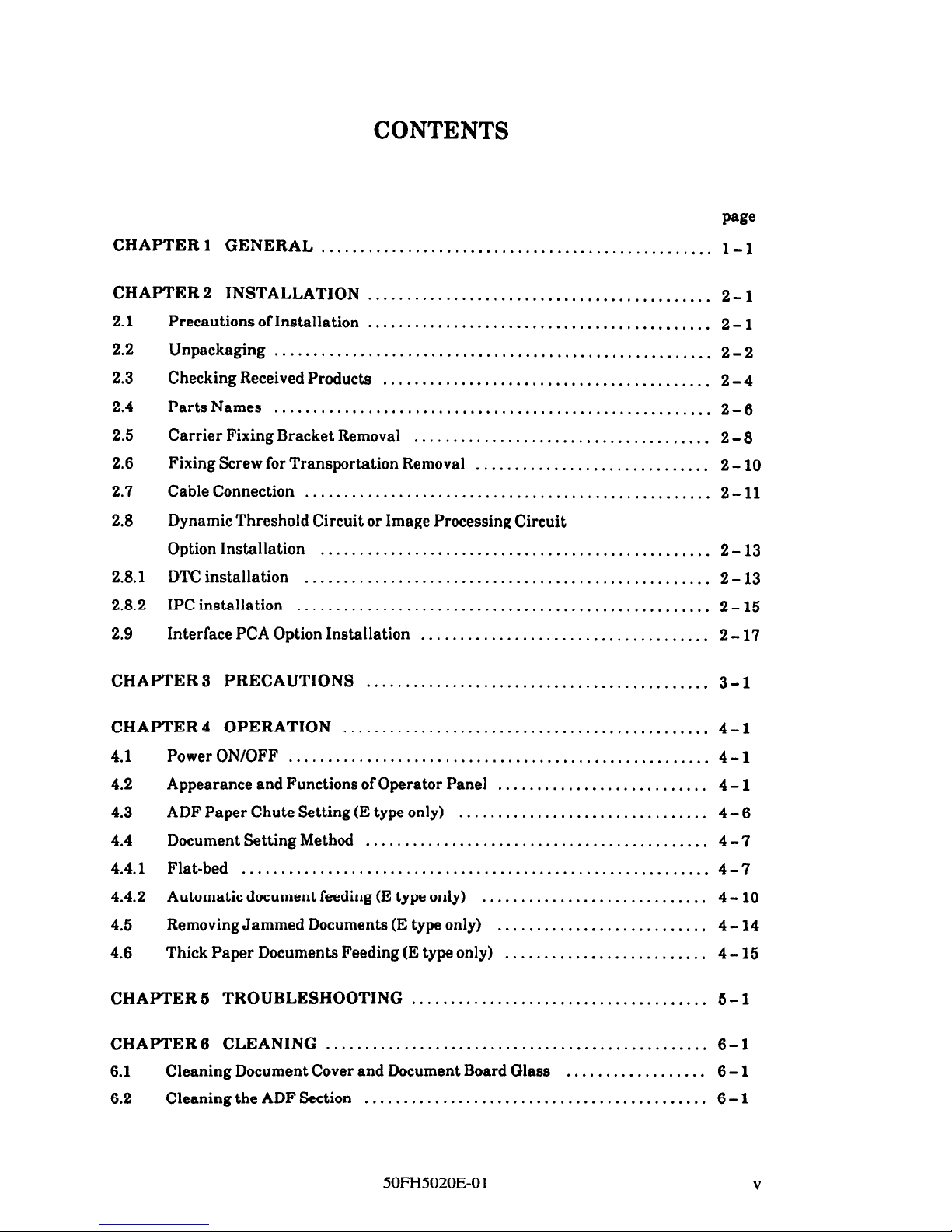
CONTENTS
CHAPTER 1
GENERAL
........................................
..........
l-l
CHAPTER 2
INSTALLATION
............................................
2-l
2.1
2.2
2.3
2.4
2.5
2.6
2.7
2.8
2.8.1
2.8.2
2.9
Precautions of Installation
............................................
2-l
Unpackaging
........................................................
2-2
Checking Received Products
..........................................
2 - 4
Parts Names
.......
..................................
...............
2-6
Carrier Fixing Bracket Removal
......................................
2 - 8
Fixing Screw for Transportation Removal
..............................
2-10
Cable Connection
....................................................
2-11
Dynamic Threshold Circuit or Image Processing Circuit
Option Installation
..................................................
2-13
DTC installation
..................
..................................
2-13
IPCinstallation
.....................................................
2-15
Interface PCA Option Installation
.....................................
2-17
CHAPTER 3 PRECAUTIONS
............................................
3-l
CHAPTER 4 OPERATION
...............................................
4 - 1
4.1
PowerON/OFF ......................................................
4-l
4.2
Appearance and Functions of Operator Panel
...........................
4 - 1
4.3
ADFPaperChuteSetting(EtypeonIy1
................................ 4-6
4.4
Document Setting Method
............................................
4 -7
4.4.1 Flat-bed
............................................................
4-7
4.4.2 Automatic document feeding (E type only)
.............................
4-10
4.5
Removing Jammed Documents (E type only)
...........................
4-14
4.6
Thick Paper Documents Feeding (E type only)
..........................
4 - 15
CHAPTER 5 TROUBLESHOOTING
......................................
5-l
CHAPTER 6 CLEANING
.................................................
6 - 1
6.1
Cleaning Document Cover and Document Board Glass
..................
6-l
6.2
Cleaning the ADF Section ............................................
6-l
50FH5020E-0 1
V
Page 5
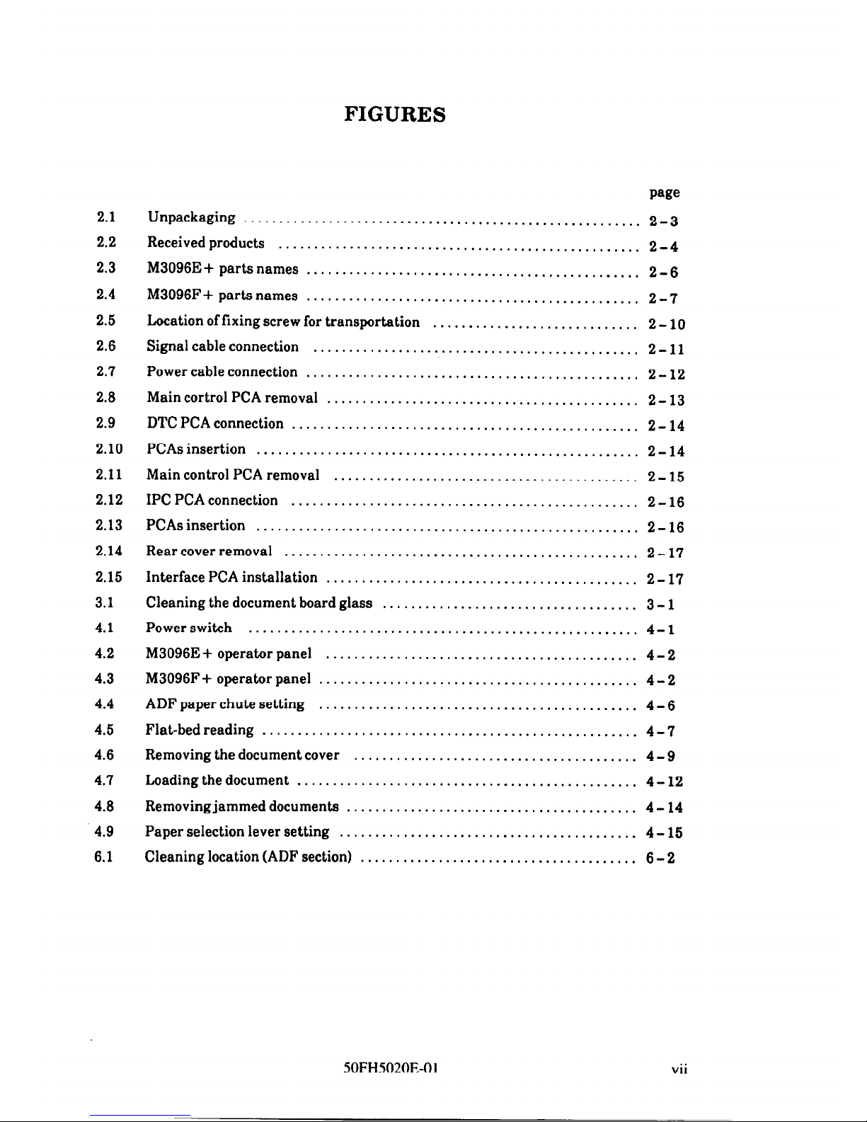
FIGURES
2.1
2.2
2.3
2.4
2.5
2.6
2.7
2.8
2.9
2.10
2.11
2.12
2.13
2.14
2.15
3.1
4.1
4.2
4.3
4.4
4.5
4.6
4.7
4.8
4.9
6.1
wee
Unpackaging .......................................
.................
2-3
Receivedproducts ................................
...................
2-4
M3096E + parts names
...............................................
2-6
M3096F + parts names
................................. ..............
2-7
Location of fixing screw for transportation
.............................
2 - 10
Signal cable connection
.................
.............................
2-11
Power cable connection
............
...................................
2-12
Main cortrol PCA removal
............................................
2 - 13
DTCPCAconnection .................................................
2-14
PCAs insertion
................
......................................
2-14
Main control PCA removal
...........................................
2- 15
IPC PCA connection
.................. ...............................
2-16
PCAsinsertion ......................................................
2-16
Rearcoverremoval ..................................................
2-17
Interface PCA installation
................
............................
2-17
Cleaning the document board glass
....................................
3 - 1
Powerswitch .......................................................
4-l
M3096E+operatorpanel
............................................
4-2
M3096F+operatorpanel
.............................................
4-2
ADF paper chute setting
.............................................
4-6
Flat-bedreading .....................................................
4-7
Removing the document cover
........................................
4 - 9
Loading the document
................................................ 4-12
Removing jammed documents
.........................................
4 - 14
Paper selection lever setting
..........................................
4 - 15
Cleaning location (ADF section)
..............................
.........
6-2
50FH5020E-0 1
vii
Page 6
TABLES
2.1
Check list
...........................................................
2-5
4.1
Switch names and functions
..........................................
4-3
4.2
Indicator names and functions
........................................
4-4
6.1
Check items
.........................................................
5-l
50FH5020E-0 1
ix
Page 7
CHAPTER 1
GENERAL
The M3096E +/F+ Image Scanner reads image information on a document and inputs the
information into the host computer.
The image scanner consists of the image reading
mechanism, document feed mechanism, microprocessor control circuit, operator panel and
power supply.
The features of this device are:
l A document as large as Double-Letter size can be read.
l High-speed reading (less than 8 seconds for Double-Letter size document)
0 High-resolution reading (400 DPI)
l Compact desktop size
l Automatic document feeder (ADF) (M3096E + only)
60FH5020E-01
l-l
Page 8

CHAPTER 2 INSTALLATION
I.
2.1
2.2
2.3
2.4
2.6
2.6
2.7
2.8
2.9
Precautions of Installation
Unpackaging
Checking Received Products
Parts Names
Carrier Fixing Bracket Removal
Fixing Screw for Transportation Removal
Cable Connection
Dynamic Threshold Circuit or Image Processing
Circuit Option Installation
Interface PCA Option Installation
This chapter explains the unpackaging procedure, installation procedure and confirmation
of operation.
2.1
Precautions of Installation
Pay attention to following matter before unpackaging and installation.
Do not install to place where the vibration way occur.
Keep the scanner out of the sun.
Do not install near the heat source.
Do not place around scanner the material which shuts off the air circulation.
Do not install to humid or dusty place.
Do not use the wall socket with connecting devices which may make noise, for
examply motor.
Use the suitable AC power source. Using unsuitable AC power source causes
trouble.
SOFH5020E-01
2-l
Page 9
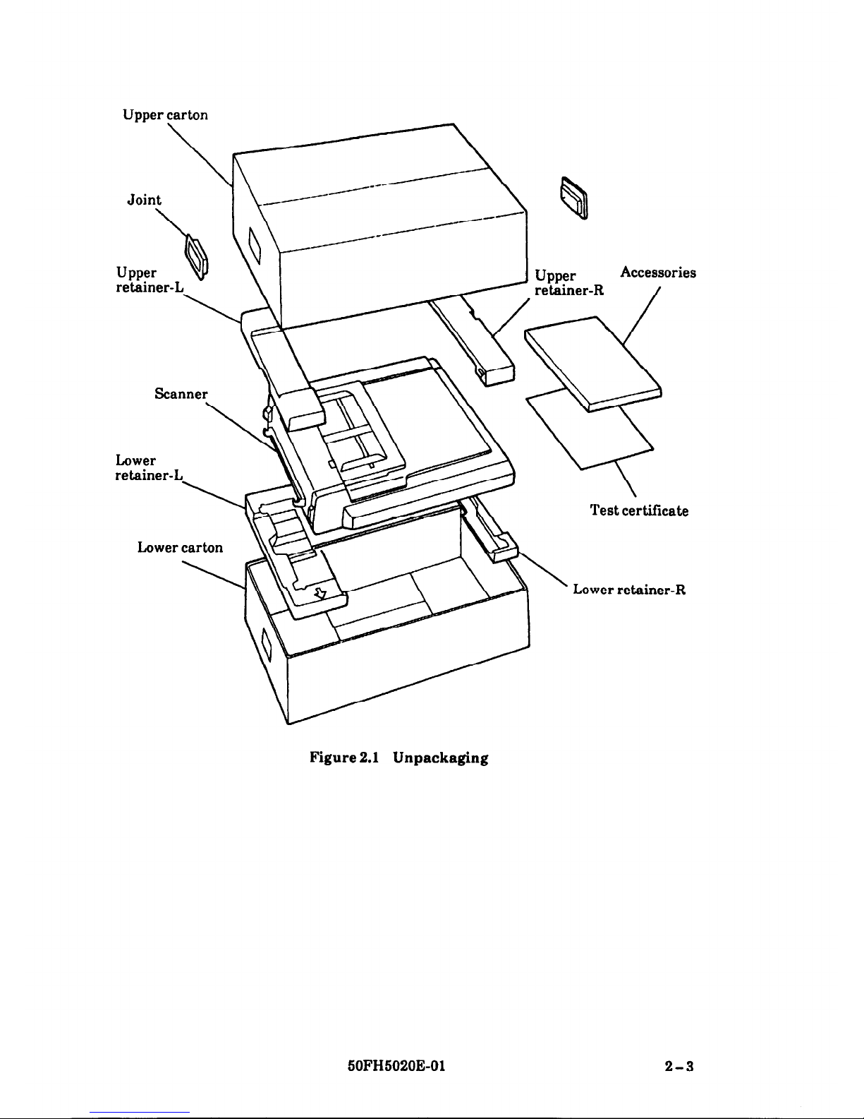
2.2
Unpackaging
Perform unpackaging according to following procedure.
Q Remove two joints.
8 Pull up the carton to remove.
0 Remove the upper retainer.
@ Take out the accessories and test certificate.
0 Take out the scanner.
8 Take out the scanner from vinyl bag and remove the protection tape.
@I Check the accessories by refering to Figure 2.2 and Table 2.1.
2-2
50FH5020E-01
Page 10
Upper carton
\
Joint
b
Upper
Q
retainer-L
Lower
retainer-
Lower carton
B
Upper
retainer-R
Accessories
/
Test certificate
Lower retainer-R
Figure 2.1 Unpackaging
SOFH5020E-01
2-3
Page 11
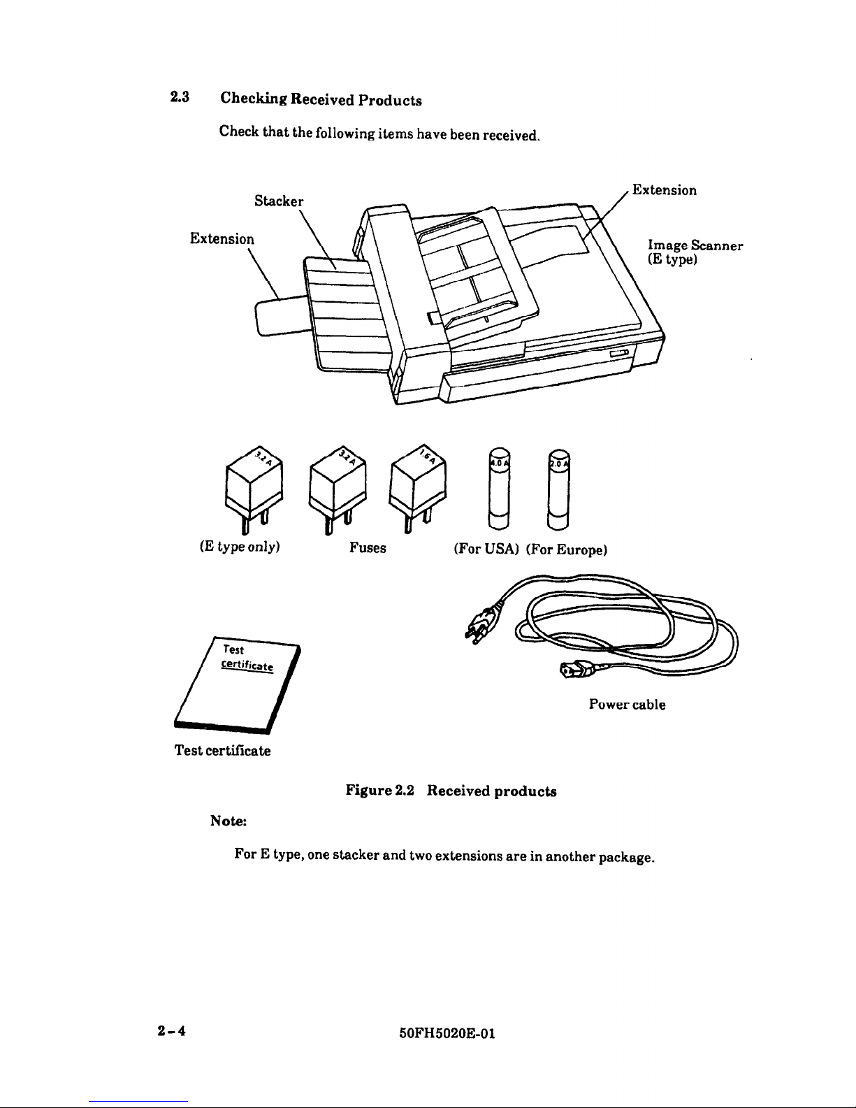
2.3
Checking Received Products
Check that the following items have been received.
Extensio
(E type only)
Test
Certificate
1-7
Fuses
(For USA) (For Europe)
Power cable
Test certificate
Note:
Figure 2.2 Received products
For E type, one stacker and two extensions are in another package.
2-4
50FH5020E-01
Page 12
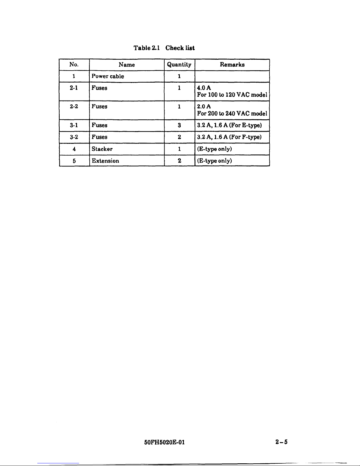
Table 2.1 Check list
I
No.
Name
1 Quantity
Remarks
I
1
I-
2-1
Power cable
Fuses
1
1
Fuses
I
1
Fuses
I
3
4.0 A
For 100 to 120 VAC model
I
3.2 A, 1.6 A (For F-type) 1
60FH5020E-01
2-5
Page 13
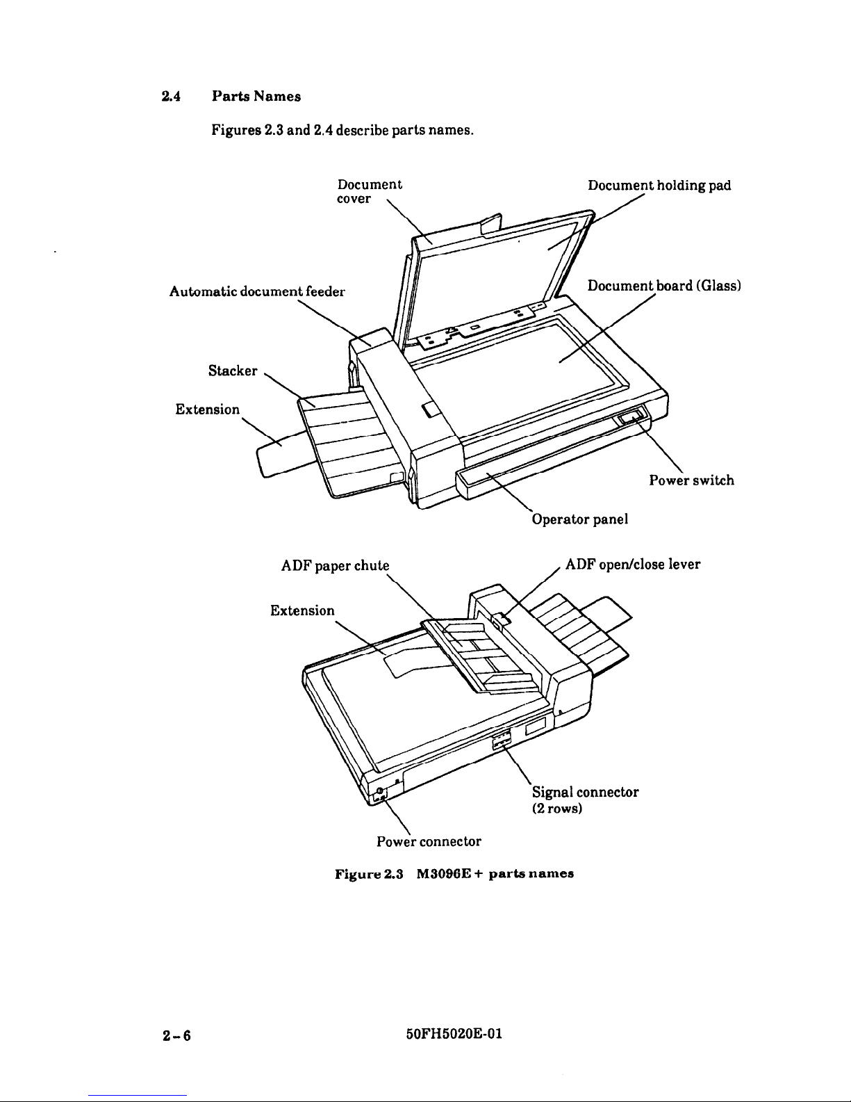
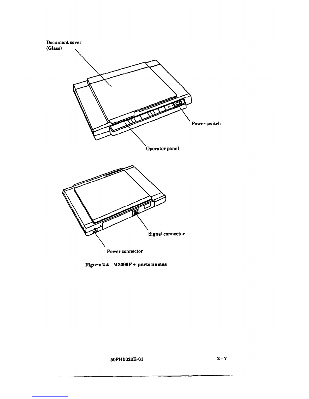
2.4 Parts Names
Figures 2.3 and 2.4 describe parts names.
Document
cover ,
DocumTt holding pad
Document board (Glass)
Extension
\
Pow:r switch
-Operator panel
(2 rows)
lever
Power connector
Figure 2.3 M3096E + parts names
2-6
50FH5020E-01
Page 14
Document cover
(Glass)
\
switch
\
Operator panel
Power connector
Figure 2.4
M3096F + parts names
2-7
SOFH5020E-01
Page 15

2.5
Carrier Fixing Bracket Removal
At first, remove the carrier fixing bracket from the base of the scanner. This
bracket fixes the carrier unit for transportation.
When the power is turned on with fixing bracket, the alarm lamp turns on. Then,
turn off the power once disconnect the power cable and remove the bracket.
CAUTION
Do not set the scanner turn over and raise.
Q Set the scanner on the edge of the desk in view of the base of ADF section.
@ Confirm with viewing from the lower side that the carrier fixing bracket is
attached.
Carrier fixing bracket
2-8
50FH5020E-01
Page 16

6
Remove the screw and remove the carrier fixing bracket. (From position @)
Install the carrier fixing bracket at position 0.
Left side
ront side
When transporting
Carrier fixing bracket
CAUTION
When transportation, shall be in position @.
SOFH6020E-01
2-9
Page 17

2.6
Fixing Screw for Transportation Removal
Open the document cover and remove the fixing screw for transportation.
Fixing screw for
Figure 2.6
Location of fixing screw for transportation
2-10
50FH5020E-01
Page 18

2.7
Cable Connection
Connect the signal cable and power cable as follows.
@
Confirm that the power switches of the image scanner and host computer have
been set to OFF.
@ Connect the image scanner to the host computer with signal cables V and R.
Rear of
To host computer
Figure 2.6
Signal cable connection
Insert the two cables as shown in Figure 3.3.
Fasten the two catches to signal cable
V and fix signal cable R with the screws.
The other end of each cable should be attached to the host computer in the same
way.
50FH6020E-01
2-11
Page 19

Insert the power cable into its connector on the rear of the image scanner.
Also insert the power cable into a 3-pin power outlet.
Power cable
(3-pin outlet)
2-12
Figure 2.7
Power cable connection
50FH5020E-01
Page 20

2.8
Dynamic Threshold Circuit or Image Processing Circuit Option Installation
2.8.1 DTC installation
(1)
Remove the main control PCA
Loosen the front cover screw and remove the front cover from the scanner.
Remove the screws “C” and “D”, the board support, and the F-plate.
(Do not remove the nickel cloth from the F-plate.)
Remove all connectors on the front end of the PCA.
Hold clamps at both ends of the PCA with hands and pull toward you.
/
F-plate
\
Front cover
Screws D
nl3
0
’ I
Screw C
Outer view of board support
Figure 2.8
Main control PCA removal
60FHS020E-01
2-13
-
Page 21

(2)
Install DTC option
(3)
Q Take on the main control PCA and connect the DTC option by 3 screws.
Figure 2.8
DTC PCA connection
Insert the PCA
Q Insert the edges of rails A and B, and insert metal bracket of main control PCA
to the rail C.
Metal bracket
2-14
Figure 2.10
PCAs insertion
60FH5020E-01
Page 22

2.8.2 IPC installation
(1)
Remove the main control PCA
Loosen the front cover screw and remove the front cover from the scanner.
Remove the screws “C” and “D”, the board support, and the F-plate.
(Do not remove the nickel cloth from the F-plate.)
Remove all connectors on the front end of the PCA.
Hold clamps at both ends of the PCA with hands and pull toward you.
F-plate
Main control PCA
Screw C
Outer view of board support
Figure 2.11 Main control PCA removai
SOFH5020E-01
2-16
-
Page 23

(2)
Install IPC option
!D
Take on the main control PCA and connect the IPC option by 3 screws.
Main control PCA
\
IPC option
Figure 2.12
IPC PCA connection
(3)
Insert the PCA
0
Insert the edges of rails A and B, and insert metal bracket of main control PCA
to the rail C.
Figure 2.13 PCAs insertion
2-16
50FH5020E-01
Page 24

2.9 Interface PCA Option Installation
Q
@
6
Loosen the rear cover screws and remove the rear cover.
Rear cover screws
Figure 2.14
Rear cover removal
Loosen the interface PCA screws and remove interface PCA.
Insert optional interface PCA with edges to rails A and B.
Interface PCA option
Screws
Figure 2.15
Interface PCA installation
60FH5020E-01
2-17
Page 25

2-18
This page is intentionally left blank.
50FH5020E-01
Page 26

CHAPTER 3
PRECAUTIONS
Q
8
6
63
Q
Use dry cloth or neutral cleanser to remove dirt from the cover, glass, document
cover, and document holding pad.
Do not use organic solvents such as thinner.
During reading, do not look directly at the light source. Keep the document
cover in place.
If the document is moved during reading, the image quality will be poor and the
read data is not guaranteed.
Position the document on the glass surface so that it will not move.
Warming up time is necessary after power-up. During warm up, the Size,
Density, Resolution and Line lamps blink and reading cannot be done. The
warming up time depends on the ambient temperature. It is approximately 3
minutes at 5 “C and 30 seconds at 25 “C.
Figure 3.1
Cleaning the document board glass
x
6
Thinner
0
6
Neutral
cleanser
50FH5020E-01
3-l
Page 27

CHAPTER 4
OPERATION
4.1
Power ON/OFF
4.2
Appearance and Functions of Operator Panel
4.3
ADF Paper Chute Setting (E type only)
4.4
Document Settig Method
4.5
Removing Jammed Documents (E type only)
4.0
Thick Paper Documents Feeding (E type only)
4.1 Power ON/OFF
The power switch is on the front of the image scanner. (See Figure 4.1.)
By pushing the side of the switch marked ” 1 ” power is connected and the power
lamp on the operator panel is lit. By pushing the side of the switch marked “ 0 “,
power is disconnected and the power lamp on the operator panel goes out. (In Figure
4.1, power is not applied.)
Figure 4.1
Power switch
4.2 Appearance and Functions of Operator Panel
Figure 4.2 to 4.5 show the operator panel for each model, Table 4.1 lists switch
names and functions, and Table 4.2 lists indicator names and functions.
60FH5020E-01 4-1
Page 28

Cl in
.
s
4
0
cl b
3
+
II 8n
3
II cl
4-2
50FH5020E-01
Page 29

Table 4.1 Switch names and functions
Switch name Indication Function
start switch None
If, in the manual mode, this switch is pressed while the
Ready lamp is lit, the read operation is started.
If this switch is pressed while reading:
Flat-bed: The read operation is immediately interrupted
and the carrier returns to the home position.
ADF: The read operation is immediately interrupted
stop switch
None
and paper that has been fed is ejected. Paper
that has been loaded into the scanner but not
yet read is ejected. If this switch is pressed
after a jam is cleared, the jam lamp goes out
and reading is enabled.
Resolution
switch
Yes
Sets the resolution. Each time this switch is pressed, the
resolution lamps light in turn, as shown below.
400 ----) 300 - 240 - 200
Document
switch
Half-tone
switch
Yes
Yes
Document reading is selected. Each time this switch is
pressed, the “Line” and “Photo” lamps light alternately.
Enables half-tone processing. Each time this switch is
pressed, the “Half-tone” lamp lights and goes out
alternately.
Density is set. Each time this switch is pressed, the
density lamps light in turn, as shown below.
(When using the option base only)
Density switch
Yes
Size switCh
Yes
Auto
v-+ Dark d (Somewhat Normal + (Somewhat Light -
dark)
light)
Sets the document size. Each time this switch is pressed,
the Size lamps light in turn, as shown below.
11x17+ A4+ 8-1/2X11 -W B4--, 8-l/!Jxll
ADF switch
Yes
Specifies whether reading is done with the ADF or from
the flat-bed. Each time this switch is pressed, the ADF
lamp lights and goes out alternately.
Landscape
Yes
Specifies whether reading is done in the portrait mode or
landscape mode. Each time this switch is pressed, the
Landscape lamp lights and goes out alternately.
60FH5020E-01
4-3
-
Page 30

Table 4.2
Indicator names and functions
Indicator
name
Power lamp
Alarm lamp
Jam lamp
Ready lamp
Resolution
lamp
Line/Photo
lamp
Half-tone
lamp
Density lam]
P
-
Lamp color
Amber
Red
Red
Green
Green
Green
Green
Green
Function
Lights when power is applied.
Lights when a device failure occurs. If this lamp lights,
urn the power off then on again. Then execute reading.
Lights when a jam occurs in the auto feed mode. If this
lamp lights, remove jammed paper and turn off this lamp
,y pushing the Stop switch. Then start reading.
Lights when the image scanner becomes ready in the mode
where reading is started with the Start switch (i.e. manual
start mode) and goes out when the Start switch is pressed
snd reading is started.
The lamp corresponding to the selected resolution lights
each time the Resolution switch is pressed. When the
main unit specifies a resolution the image scanner
zomplies accordingly.
I’he read processing lamp corresponding to the setting of
the Document switch lights.
Line:
Compensate the reflection of the background of the
document.
Photo:
Scanner memorizes the white target of it as the
white level.
When power is applied and the initial state is specified,
Line is selected. When the host computer has specified the
document, the scanner complies accordingly.
When half-tone reading has been selected with the Halftone switch (dither processing), this lamp lights. When the
Automatic Separation text and photo reading has been
selected with Half-tone switch, this lamp blinks. This
lamp is not lit after powered on without IPC option. This
lamp blinks after powerd on with IPC option. When the
host computer specifies Half-tone, the scanner complies
accordingly.
Each time the Density switch is pressed, the Density lamp
lights.
Dark output (for light document image):
Select the Dark lamp.
Light output (for dark document image):
Select the Light lamp.
When power is applied or the initial state is specified, the
Normal lamp lights. If the DTC option is installed, the
Auto lamp lights when power is applied. When the host
computer specifies density, the scanner complies
accordingly.
4-4
50FH5020E-01
Page 31

Table 4.2~continued
Indicator
name
Lamp color
Function
Size lamp
Green
The Size lamp goes on according to the size selected with
the Size switch. When power is applied or the initial state
is specified, the “11 x 17” lamp lights. When the host
computer specifies the size, the scanner complies
accordingly.
The lamp corresponding to the state selected with the ADF
switch lights.
ADF lamp
Green
ON: Auto feed reading
OFF: Flat bed reading
When power is applied or the initial state is host computer
specifies the state, the scanner complies accordingly.
Landscape
lamp
Green
The lamp corresponding to the document form selected
with the Landscape switch lights.
ON:
Landscape mode
OFF: Portrait mode
For the document setting for each mode, see Section 4.4.
When power is applied or the initial state is specified, this
lamp goes out. When the host computer specifies the
document form, the scanner complies accordingly.
50FH5020E-01 4-5
-
Page 32

4.3 ADF Paper Chute Setting (E type only)
ADF
paper
hen the documents
reading
using ADF)
ocument cover
Figure 4.4
ADF paper chute setting
When the documents reading using ADF, set the ADF paper chute as follows.
Hold the handle of document cover with one hand, and grip the edge of ADF
paper chute with another hand.
Raise up the ADF paper chute till hear the dick sound.
When down the ADF paper chute, push down it to the document cover.
4-6
50FH5020E-01
Page 33

4.4 Document Setting Method
4.4.1 Flat-bed
Handle
(1)
Document board (Glass)
Figure 4.5 Flat-bed reading
When the document size is 11 X 17 or smaller.
If the document is to be read on the flat-bed, follow the steps below.
Open the document cover.
Put the document on the document board with the image face down with the
upper end to the left. Correct any curled or folded documents.
Position the left side and upper end of the document in line with the reference
frame so that the upper-left corner of the document coincides with the reference
mark (triangle mark) at the upper-left of the reference frame.
If the document is not set correctly, reading is not done correctly.
SOFH5020E-01 4-7
Page 34

Close the document cover slowly.
If the document cover is closed too quickly, the document may be moved.
During reading, do not press or open the document cover.
Select the reading mode from the control panel and start reading. If
portrait/landscape is selected according to the document size or form, reading
time can be reduced.
The relationship between the document form and reading mode is as follows:
Landscape mode
Portrait mode
Flat-bed
Short side
( Longside i l
Flat-bed
After reading ends, open the document cover and take out the document.
(2)
When the document is a thick book
Q
c3
Open the document cover and place it on the glass surface.
If the document is thick, do not close the document cover.
That part of the document in close contact with the glass will be read correctly,
but any part which is not in contact with the glass may be distorted or unclear,
so care must be taken.
4-8
50FH6020E-01
Page 35

(3)
When the document size is larger than Double-Letter.
Document cover
White sheet
To remove the document
Figure 4.6 Removing the document cover
As shown in Figure 4.7, pull the document cover in the direction of the arrow
and remove it.
Lay the document on the surface of the glass.
Place the document cover on the document with the document holding pad
facing down.
After reading, assemble the document cover.
50FH5020E-01
4-9
Page 36

4.4.2
Automatic document feeding (E type only)
When the document is read in the automatic document feed mode, follow the steps
below. If these steps are not closely followed, a feed error may occur.
Place the document upside down.
Arrange the document as shown below. (See the next page.)
End
Open the right and left guides of the ADF paper chute, and set them
approximately 5 mm wider than the document width.
Position the document face down and put the ends of the lower 2 or 3 sheets into
the auto feeder hole.
Line up the guides with the document sides. (Skewing may occur if there is a
gap between the guides and document.)
Slide the pages down until they hit the far end of the auto feeder hole.
Position the remaining document sheets on the paper chute.
Insert these sheets until they hit the far end of the auto feeder hole.
4-10
50FH5020E-01
Page 37

AnFling the document sheets
1.
Place the document face down on a flat surface, with its upper end to the left. (a)
2.
Lift the sheets (maximum 4 mm for A4 or smaller, maximum 2 mm for larger
than A4) with both hands.
3.
Hold the sheets tightly with your left hand and bend the sheets as shown in (b).
4. Grip tightly with your right hand, loosen the grip of your left hand, and
straighten the sheets as shown in (c).
5.
Repeat operations 3 and 4 as often as necessary.
(a) (b) (cl
upper end
Handling sheets
15 - 20mmJ
Handling sheets
Take a 2 to 4 mm thickness of sheets.
Lightly hold both ends with both hands. Bend
the sheets as shown. Hold the sheets tightly with both hands then straighten the
sheets. The sheets swell and air is introduced between them. Repeat this operation
two or three time. Turn the sheets through 90” and repeat the entire operation.
SOFH5020E-01
4-11
Page 38

Q
Sheet suitability
A4 or letter size or smaller:
Maximum thickness approximately 4 mm
B4, A3, B3, A4, and legal sizes larger then A4 :
Maximum thickness approximately
2mm
Left guide
Auto
feeder hole
Right guide
Document
(rear surface)
ADF paper chute
Document size scale
Figure 4.7 Loading the document
Select the reading mode from the control panel and start reading. If selection of
the document size or format (portrait/landscape) is wrong, reading of the entire
document may fail, so care must be taken.
The relationship between the document format and reading mode is as shown
below.
4-12
50FH5020E-01
Page 39

Portrait mode Landscape mode
Document
---lz?l
Long side
w
\
Auto feeder unit
Paper chute
Document
@
After reading is completed, remove the document from the stacker.
Attention items
(1)
(2)
(31
(4)
Remove clips and staples from the document.
Dry any wet ink.
Line up the document (to avoid skewing).
Use the flat bed for the following types of document.
(a)
Wrinkled, curled or folded documents
0-4
Transparent documents
(c)
Documents treated with a glossy coating
(d)
Damaged documents
(e)
Very thin documents
Kl
Very thick documents
(Ed
Documents smaller than A5 size
(h)
Carbon paper or thermal paper
(2
Cloth, metal sheets, OHP sheets, photographs
W
Envelopes or pasted document
04
Documents of uneven thickness
50FH5020E-01
4-13
Page 40

4.6
Removing Jammed Documents (E type only)
ADF open/close lever
ADF paper chute
Figure 4.8 Removing jammed documents
Remove the rest documents from the ADF paper chute.
Pull up the ADF open/close lever to direction @ to unlock the ADF section.
Turn up the ADF section to direction @ to open the ADF section.
Remove the jammed documents.
Confirm no documents is on the ADF paper chute, and turn down the ADF
section.
Set the ADF section to lock position with pulling up the ADF open/close lever.
Push down the ADF open/close lever.
Reading is available to press the stop switch.
4-14
50FH5020E01
Page 41

4.6 Thick Paper Documents Feeding (E type only)
Paper selection lever
Figure 4.9 Paper selection lever setting
When reading the thick paper documents using the ADF, set the paper selection
lever as follows.
Q
8
6
@
Open the ADF section. (Refer to section 4.5, Q to 6)
Set the paper selection lever to THICK side using the ballpoint pen or sharp
pencil, etc.
The paper selection lever is located at the inner part of the indication seal
NORMAL f) THICK.
Close the ADF section. (Refer to section 4.5, @ to @)
Reading is available to press the stop switch.
Note:
When the paper selection lever is always set to the THICK side, the thin paper
is not fed smoothly. Then the paper selection lever is set to NORMAL side.
50FH5020E-01
4-16
Page 42

CHAPTER 5
TROUBLESHOOTING
If a problem occurs, check the following:
Table 6.1 Check items
Case
B No Power
Possible reason
l The power
plug is not
connected.
The power
switch has not
been set to “1”.
Check:
switch
) Reading
a The Ready
l Press the Start switch
and can not
lamp is it lit
be started.
(i.e. The
300 240 200
manual start
non
Ready
0 Power
mode has been
selected.)
pesalution, * * E ;;
D Pictures
l Density
l Press the Density switch and adjust density.
and photo-
setting error
graphs
l Not in half-
l Press the Half-tone switch.
cannot be
read
.,I, ~~
l Clean the glass. (Use dry cloth or neutral cleanser.
Do not use organic solvents such as thinner.)
50FH5020E-01
5-l
Page 43

Table 5.1-continued
Case
Possible reason
Check:
D Characters 0 Density
l Press the Density switch and adjust density.
or lines are
setting error
not read l Half-tone is
a Press the Half-tone switch to reset half-tone mode.
well.
set ~~
0 Dirt on glass
surface a Clean the glass surface. (Use dry cloth or neutral
cleanser to remove dirt. Do not use thinner.)
x
8
Thinner
0
6
Neutral
cleanser
B Unclear
image
D Distorted
image
l Document
l During reading, close the cover and do not move the
moved during document.
reading
l Document not
l Adjust the document so that it is in close contact with
in contact with the glass.
glass surface
D The check
l Device failure
l Connect power again. If the check lamp still lights,
lamp
call your dealer or service agent.
l Check the carrier fixing bracket is removed.
5-2
50FH5020E-01
Page 44

CHAPTER 6
CLEANING
6.1
Cleaning Document Cover and Document Board
Glass
6.2 Cleaning the ADF Section
6.1
Cleaning Document Cover and Document Board Glass
Use the dry cloth or neutral clenser to remove dirt from the cover, grass, document
cover, and document holding pad.
Do not are arganic solvents such as thinner.
6.2
Cleaning the ADF Section
When the following matter often occurs using the ADF, clean the ADF sccording to
the cleaning procedure.
l
Documents is not fed smoothly or certainly.
l
Several documents is fed in a same time.
0
Reading result is not so good.
@
Open the ADF section. (Refer to section 4.5, @I to 6)
Q
Use the dry cloth or isopropyl alcohol to softly remove dirt and dust as follows.
l Pad:
Cleaning direction is upper to lower.
Be careful not to hooking the pick spring when cleaning.
l Glass : Cleaning direction is right to left.
Be careful not to hooking the sensor arm when cleaning.
0
Pick roller
l Feed roller
>
Cleaning softly not to the surface of roller damage.
0 Exiting roller
l Guide shaft (White colored six-sided shaft) :
Do not press the shaft so strong.
So that the shaft is bend, because
reading quality reduces.
@
Close the ADF section. (Refer to section 4.5,8 to a)
50FH5020E-01
6-l
Page 45

Pad
Feed roller
Glass
\
(The arrow is show the
/
cleaning direction,
attention to bend of the
sensor arm)
(The arrow is
show the cleaning
direction)
\
Guide shaft ’
(Attention to bend
of this shaft)
\
Existing roller
(Opposite roller cleaning too)
Figure 6.1
Cleaning location (ADF section)
6-2
50FH6020E-01
 Loading...