

Page 1

Copyright
Fujitsu Limited has made every effort to ensure the accuracy and completeness of this document. However, as
ongoing development efforts are continually improving the capabilities of our products, we cannot guarantee the
accuracy of the contents of this document. We disclaim liability for errors, omissions, or future changes.
LifeBook is a trademark of Fujitsu Limited.
Microsoft, Windows, MS, MS-DOS, and Windows NT are registered trademarks of the Microsoft Corporation of the
United States in the United States and other countries.
Intel is a registered trademark of the Intel Corporation of the United States.
Celeron is a trademark of the Intel Corporation of the United States.
NeoMagic MagicMedia 256AV and NeoMagic MagicMedia 256AV+AC97 Driver (WDM) are trademarks of
NeoMagic™ Corporation.
Puma Technology, Intellisync is a trademark of Puma Technology Corporation of the United States.
Phoenix is a registered trademark of Phoenix Technologies Corporation of the United States.
K56flex is a trademark of Rockwell International Corporation and Lucent Technologies Corporation.
Magic Packet is a registered trademark of Advanced Micro Devices, Inc.
Other product names are trademarks or registered trademarks of their respective companies.
Other products are copyrighted by their companies.
Copyright© 1981-1999 Microsoft Corporation, All rights reserved.
Copyright© 1999 Phoenix Technologies, Ltd., All rights reserved.
All other products are trademarks or registered trademarks of their respective companies.
Explanations of the adjustments for the track pad cursor control are taken in part from the ALPS GlidePoint Driver
User’s Guide, copyright by LCS/Telegraphics in 1996.
© Copyright 1999 Fujitsu Limited. All rights reserved. No part of this publication may be copied, reproduced, or
translated, without the prior written consent of Fujitsu Limited. No part of this publication may be stored or transmitted in any electronic form without the written consent of Fujitsu Limited.
DECLARATION OF CONFORMITY
according to FCC Part 15
Responsible Party Name : FPCA
Declares that product: Model : LifeBook B2130
Address : Fujitsu PC (Asia) Pte Ltd
200 Pandan Loop
#05-03, Pantech 21
The Computer Centre
Singapore 128388
Telephone : 65-776 0688
This device complies with Part 15 of the FCC Rules. Operations are subject to the following two conditions:
(1) This device must not be allowed to cause harmful interference, (2) This device must accept any interference
received, including interference that may cause undesired operation.
Page 2
NOTATION IN THIS DOCUMENT
Warnings
This manual uses a variety of icons as visual marks so that you can use this computer safely and
correctly and avoid damage and danger to yourself and to others. These icons and their meanings
are as follows. Please learn these icons before reading this manual. Learning these icons will be
useful for understanding this manual.
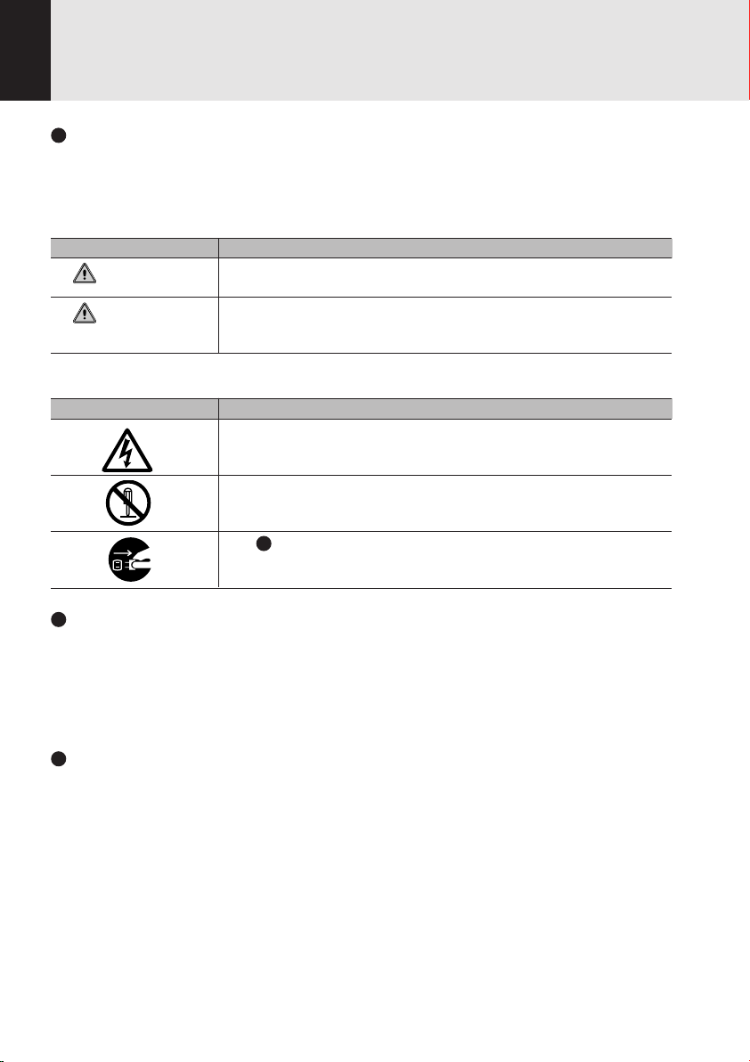
Icon Meaning
WARNING
CAUTION
The symbols below are used together with the icons above to indicate what type of danger or
damage is involved.
Symbol Meaning
Incorrect handling or ignoring this warning can cause a dangerous
situation that could result in death or severe injury.
Incorrect handling or ignoring this warning can cause a dangerous
situation that could result in moderate or minor injury or could result in
equipment damage.
The symbol indicates a w arning or caution. The symbol inside the
indicates the concrete nature of the warning. (The example on the left
is a caution for electric shock.)
The circle and slash indicates prohibited behavior. The symbol inside
the circle indicates the concrete nature of the prohibition. (The
example on the left indicates that disassembly is prohibited.)
The indicates instructions that must be followed. The symbol inside
indicates the concrete nature of those instructions. (The example on
the left tells you to unplug the power plug from the socket.)
Key notation and operation methods
Explanations of key operations do not show all the characters on the keyboard. Instead they
indicate just the keys necessary to the explanation as follows.
Examples: [Ctrl] key, [Enter] key, [ → ] key
When multiple keys are to be pressed at the same time, this is indicated by connecting them with
[+].
Examples: [Ctrl] + [F3] keys; [Shift] + [ ↑ ] key
Screen examples
The screens shown in this manual are examples. Please understand that the file names and
screens you use may be different.
Page 3

Notation in text
Here is what symbols in text mean.
Symbol Meaning
Critical Points
Indicates a point necessary for correctly operating the hardware or
software.
Gives the meaning and brief explaination of a term.
Column
→ Indicates the page to see elsewhere in this manual.
Command input (key input)
Within the text of this manual, command input (giving commands to the computer by pressing
keys) is indicated as follows.
Example:
In the position indicated in the example above by the ↑, the space left between the characters
indicates that a space needs to be left in the entry by pressing the space bar (the long key with
nothing written on it at the center of the front of the keyboard). Commands are written in this
manual as lowercase latin letters, but uppercase letters may be used.
Product names
The following product names are abbreviated as follows in this manual.
“Microsoft® Windows® 98 operating system” is written as “Windows 98”.
“Microsoft® MS-DOS® operating system Version 6.2/V” is written as “MS-DOS”.
“Microsoft® Windows® operating system Version 3.1” is written as “Windows 3.1”.
“Microsoft® Windows NT® Server network operating system Version 3.5” and “Microsoft® Windows NT® Workstation operating system Version 3.5” are both written as “Windows NT 3.5”.
“Microsoft® Windows NT® Server network operating system Version 3.51” and “Microsoft® Windows NT® Workstation operating system Version 3.51” are both written as “Windows NT 3.51”.
“Windows NT 3.51” and “Windows NT 4.0” are both written as Windows NT.
“Fujitsu Lifebook” is written as “this computer” or “the computer main unit”.
dir c:
↑
Page 4

Configuration of this Manual
SECTION 1
This section explains basic operations and basic items for using this computer, including the
names of the parts and their functions, quick point IV operation methods, connector box handling, and battery operation.
SECTION 2
This section explains installation of options for this computer.
SECTION 3
This section explains the BIOS setup program, which is necessary for setting the date and time
and power conservation mode. This section also explains how to set the password for protecting
data in this computer.
SECTION 4
This section explains what to do when trouble occurs with this computer and when messages are
displayed. Read this section as the necessity arises.
SECTION 1
SECTION 2
SECTION 3
SECTION 4
Page 5

CONTENTS
SECTION 1
1. Names of the Parts and their Functions .............................2
Front/Top ............................................................................................. 2
Left Side/Right Side ............................................................................. 4
Rear/Bottom ........................................................................................ 6
Connector Box ..................................................................................... 7
Status Indicator LCD ........................................................................... 8
2. Quick Point IV ......................................................................10
What is the Quick Point IV? ............................................................... 10
Quick Point IV Usage ........................................................................ 11
3. About the touch panel ........................................................12
What is the touch panel? ................................................................... 12
How to use the touch panel ............................................................... 13
Calibrating the touch panel ................................................................ 14
4. Keyboard ..............................................................................17
Keyboard ........................................................................................... 17
Numeric Keypad Mode ...................................................................... 17
Names of the Main Keys and their Functions .................................... 18
5. Switching on the Power ......................................................20
Switching on the Power ..................................................................... 20
6. Switching off the Power ......................................................22
Precautions when Switching off the Power ....................................... 22
Switching off the Power ..................................................................... 22
7. Suspend/Resume Function ................................................ 24
What is the Suspend/Resume Function? .......................................... 24
Suspending ....................................................................................... 24
Precautions for Suspending .............................................................. 26
Resuming .......................................................................................... 27
8. Battery ..................................................................................28
Battery Charging ............................................................................... 28
Battery Operation .............................................................................. 29
Checking the Remaining Battery Charge .......................................... 30
Low Battery State .............................................................................. 31
Replacing the Internal Battery Pack .................................................. 32
Precautions for Battery Pack ............................................................. 34
9. Connector Box .....................................................................35
Connecting the Connector Box.......................................................... 35
Disconnecting the Connector Box ..................................................... 36
10. Built-in LAN (local-area network) device ..........................37
Connection ........................................................................................ 37
Page 6

SECTION 2
11. Built-in Fax Modem ............................................................. 38
Connection ........................................................................................ 38
1. Options ................................................................................. 40
Options .............................................................................................. 40
2. PC Cards .............................................................................. 42
Precautions for PC Cards .................................................................. 42
Installing PC Cards ............................................................................ 43
Removing PC Cards .......................................................................... 43
3. Expansion RAM Modules ................................................... 46
Installing an Expansion RAM Module ................................................ 46
Removing an Expansion RAM Module .............................................. 48
4. Floppy Disk Unit ..................................................................50
Installing a Floppy Disk Unit .............................................................. 50
Precautions for Floppy Disk Unit ....................................................... 51
Removing a Floppy Disk Unit ............................................................ 52
What is a Floppy Disk? ...................................................................... 53
Precautions on Handling ................................................................... 54
Loading/Ejecting a Floppy Disk ......................................................... 55
5. CCD Camera ........................................................................56
Connecting a CCD Camera ............................................................... 56
6. Mouse ................................................................................... 58
Connecting a Mouse ......................................................................... 58
Using the Mouse ............................................................................... 58
7. Numeric Keypad ..................................................................60
Connecting a Numeric Keypad .......................................................... 60
SECTION 3
SECTION 4
8. Printer ................................................................................... 61
Connecting a Printer .......................................................................... 61
9. CRT Monitor .........................................................................63
Connecting an External CRT Monitor ................................................ 63
10. One Touch Operation buttons ............................................65
Checking new arrival of E-mail .......................................................... 66
1. BIOS Setup...........................................................................68
2. POST Diagnostic Screen .................................................... 93
1. When This Happens ............................................................96
Page 7

SECTIONSECTION
SECTION
SECTIONSECTION
SECTIONSECTION
SECTION
SECTIONSECTION
11
1
11
11
1
11
This section explains basic
operations and basic items for
using this computer, including the
names of the parts and their
functions, quick point IV operation
methods, connector box handling,
and battery operation.
SECTION 1
Page 8
SECTION 1
1. Names of the Parts and their Functions
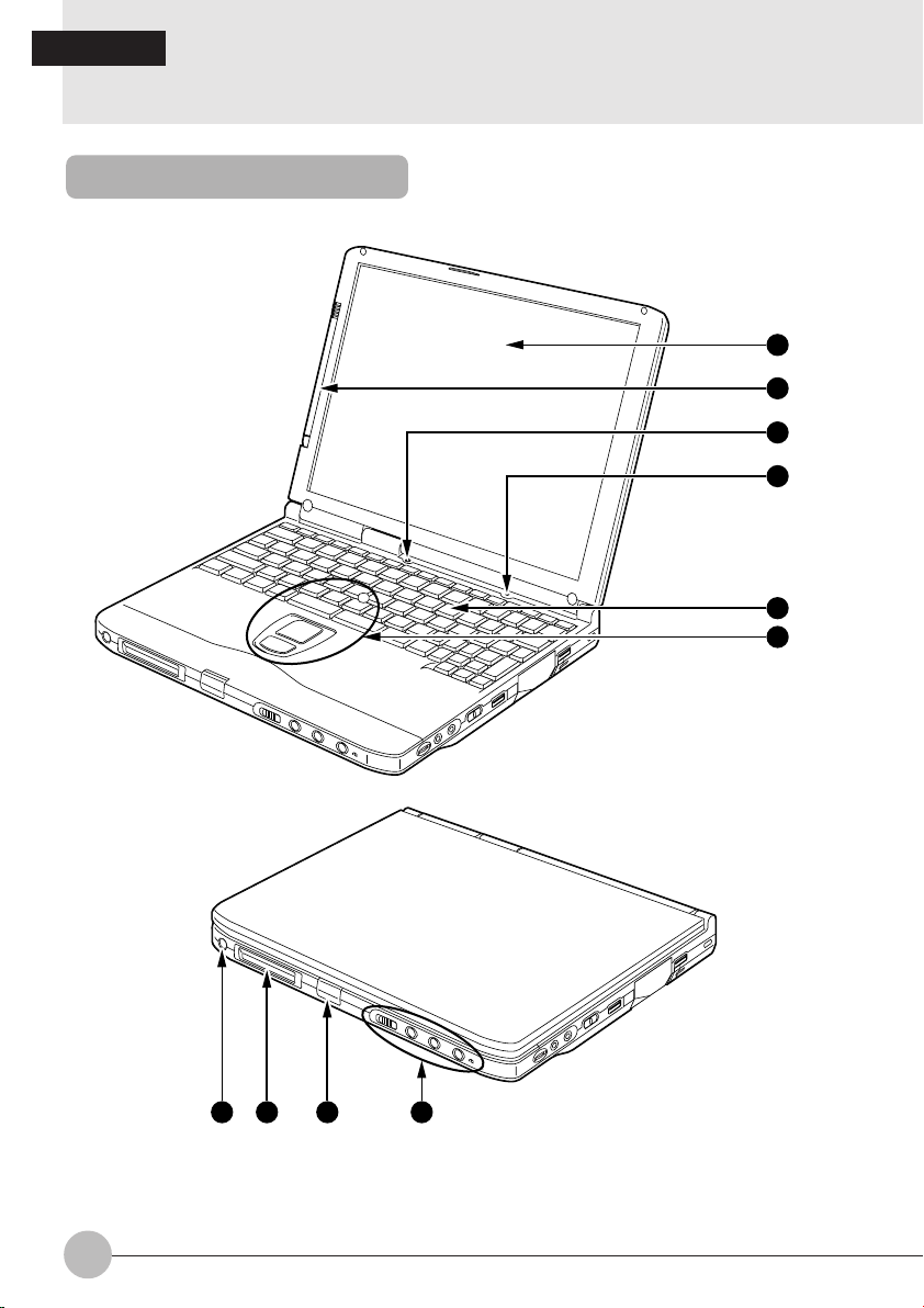
Front/Top
1
2
3
4
5
6
7 8 9 10
2
Page 9

1 LCD panel
Displays text, graphics, etc.
The LCD is covered with a touch-sensitive panel if your computer is a touch-panel model.
Critical Point
The TFT color LCD panel used with this computer has been made using high resolution
technology, but there might be dots that are always lit up or always not lit up on part of the
screen.
There may be some slight inconsistencies on the LCD panel with variations in temperature.
Please note that this is not a malfunction.
2 Pen holder
Holds a pen (stylus) if your personal computer is a touch-panel model.
3 Cover close switch
When the LCD panel is closed, this switch turns off the backlight and suspends operation of the
personal computer.
4 Condenser Microphone
Allows sound (monaural) recording.
5 Keyboard
Keys are pressed to give commands to the computer main unit.
6 Quick Point IV
This operates the mouse pointer.
7 Suspend/Resume switch
This switch suspends/resumes the computer main unit. From here on, it is written as SUS/RES
switch.
8 LCD
Displays the status of the computer main unit. See “Status Indicator LCD”.
9 Latch
This is pressed to release the lock when the LCD panel is opened.
! One-touch operation button
Allows you to launch application software or check the arrival of an e-mail.
SECTION 1
3
Page 10
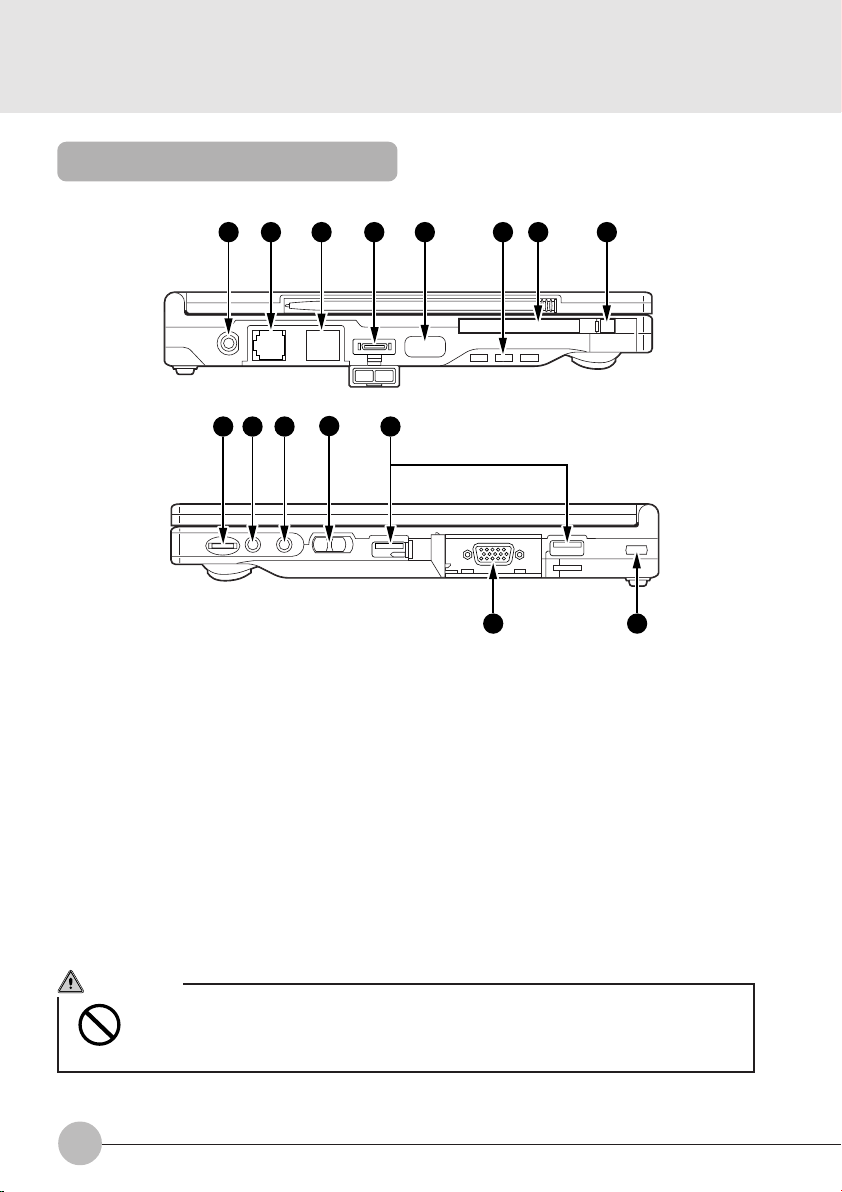
Left Side/Right Side
14 15 171611 12 13 18
19 20 21
22
23
24 25
" DC-IN connector
Connector for connecting the AC adaptor that comes with this computer.
# Modular jack
A modular jack is provided for some models.
$ LAN connector
A LAN connector is provided for some models.
% Mini-serial connector
A mini-serial connector. (Not available for this model)
& Infrared communications port
Interface for carrying out infrared communications.
( Air-cooling fan
Exhausts heat from your personal computer.
CAUTION
BREAKDOWN
Be careful not to block the air-cooling fan vent, otherwise heat will accumulate inside
the computer, causing damage to it.
4
Page 11

) PC card slot
Slot for inserting separately sold PC cards.
This PC card slot is identified as the “slot-1”, which is connected with the main unit of this personal computer.
~ PC card eject/lock button
Press this button to eject the PC card.
This button also serves as the PC card lock that prevents the inserted PC card from accidentally
getting out of the PC card slot.
+ Volume control
Adjusts the sound volume. Turning it towards you lowers the volume; turning it away from you
raises it.
Critical Point
If the volume is raised too high when using a microphone, howling may occur between the
speaker and the microphone.
, Headphone jack
For connecting commercially available headphones.
Critical Point
Things that can be fitted to the headphone jack.
- Headphones, earphones, amplifier-installed external speakers (mini-plug with 3.5mm outer
diameter. However you may not be able to fit them because of the shape, so check before
inserting.)
- Microphone jack
Can be connected with a commercially available microphone.
. MAIN switch
This is the switch for turning the power to the computer main unit on and off.
/ USB connector
Connector for connecting a peripheral equipment which meets the USB standard.
: CRT connector
Connect an optional CRT display to this connector.
; Anti-theft lock
Can be connected with a commercially available anti-theft cable.
SECTION 1
Critical Point
The anti-theft lock is for the Kensington Microsaver Security System.
5
Page 12
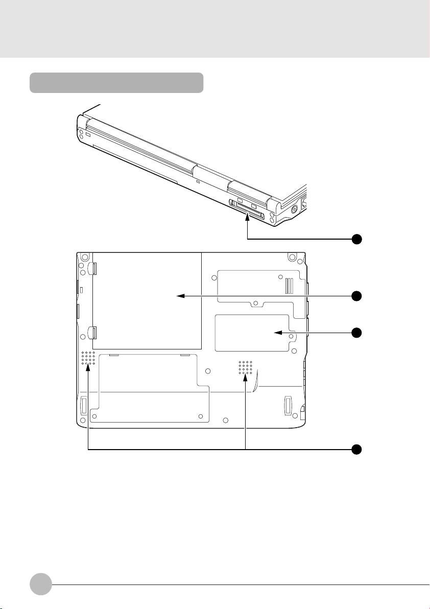
Rear/Bottom
26
27
28
< Connector box connector
Connect the connector box to this connector.
= Internal battery pack
The internal battery pack is mounted here.
> Expansion RAM module slot
Slot for fitting a separately sold expansion RAM module.
? Speaker
Outputs the sound of the computer main unit.
6
29
Page 13
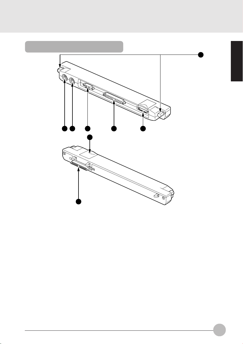
Connector Box
1
2 3 4 5 6
7
8
1 Connector lock
After connecting the connector box to the personal computer, turn these connector locks to
secure the connection between them.
2 Mouse connector
Connect an optional PS/2 mouse.
3 Extension keyboard connector
Connect an optional keypad, etc. to this connector.
4 Serial connector
Connect an optional unit conforming to the RS-232C interface standard to this connector.
5 Parallel connector
Connect an optional unit such as a printer, etc. to this connector.
6 Floppy disk unit connector
Connect an optional floppy disk unit to this connector.
7 Connector release lever
Raise this lever to detach the following connector from your personal computer.
8 Connector box connector
Connect the connector box to the personal computer by this connector.
SECTION 1
7
Page 14
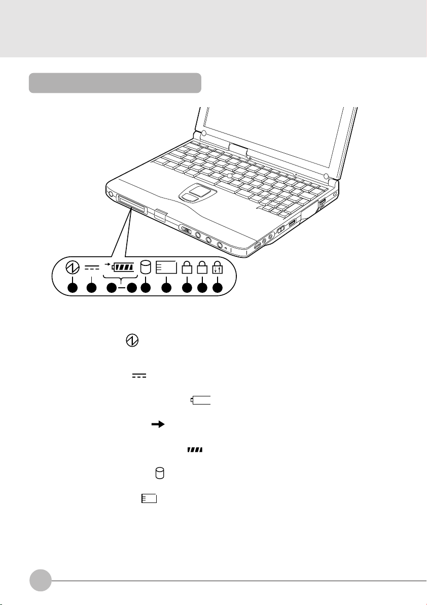
Status Indicator LCD
1
1 2 9 10
5 7 86
3
1
1
A
1 SUS/RES indicator ( )
When this computer is operating, this indicator lights up; when the computer is in suspend mode,
this indicator flashes or goes out.
2 AC adaptor indicator ( )
Lights up when the power is being supplied from the AC adaptor.
3 Battery pack mounting indicators ( 1, )
Lights up when the built-in battery pack is used as the power supply.
4 Battery charging indicator ( )
Lights up when the battery is charging; flashes when the battery is too hot or cold to charge.
5 Remaining battery charge indicator ( )
Displays the amount of charge remaining in the battery.
6 Hard disk access indicator ( )
Lights up while the internal hard disk is being accessed.
7 PC card access display (
Lights up while the PC card is being accessed.
1
)
8
Page 15
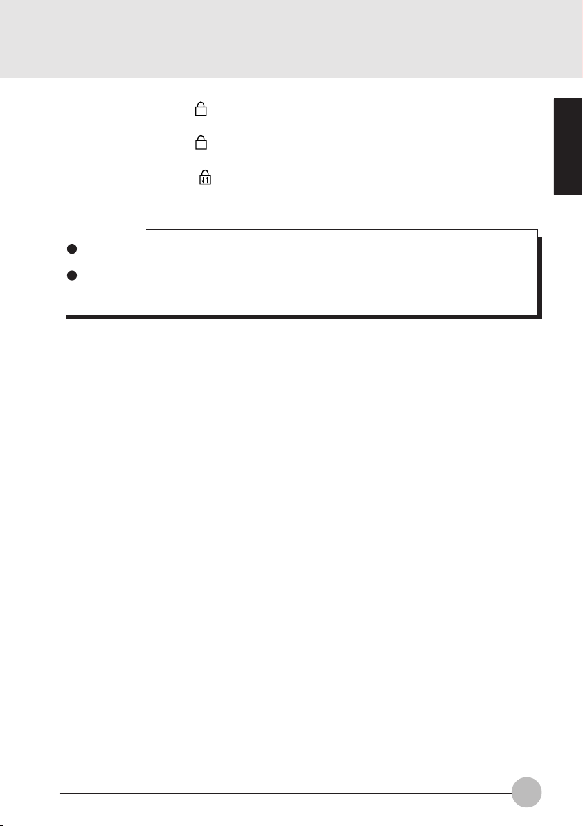
8 Num Lock indicator (
Lights up when [Num Lk] is pressed to put the keyboard into numeric keypad mode.
9 Caps Lock indicator (
Lights up when [Shift] + [Caps lock] is pressed to put the keyboard into CAPS mode.
)
1
)
A
! Scroll Lock indicator ( )
Lights up or goes out each time the [Scr Lk] keys is pressed.
Critical Point
If you switch off the main switch or operate the SUS/RES switch while the hard disk access
indicator is lit, the data being accessed may be destroyed.
When the main switch is switched off, all the indicators other than charging go off. However,
the AC adaptor lamp comes on regardless of the status indicator lamp when power is being
supplied.
SECTION 1
9
Page 16
SECTION 1
2. Quick Point IV
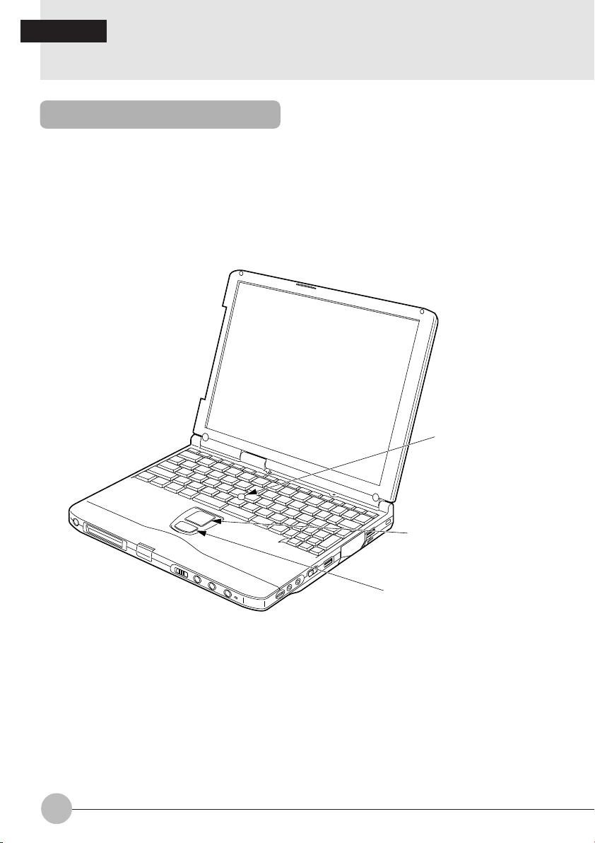
What Is the Quick Point IV?
The Quick Point IV is a handy pointing device that allows you to move the mouse pointer with a
fingertip. It is composed of a stick at the center of the keyboard and buttons on this side of the
keyboard.
The stick acts like a mouse ball and you can move the mouse pointer in any direction on the screen
by moving the stick to and fro, and to the right and left with a fingertip.
The upper button has the same function as a mouse left button and the lower button as a mouse right
button, though their functions vary depending on the software used.
Operating surface
10
Left button
Right button
Page 17
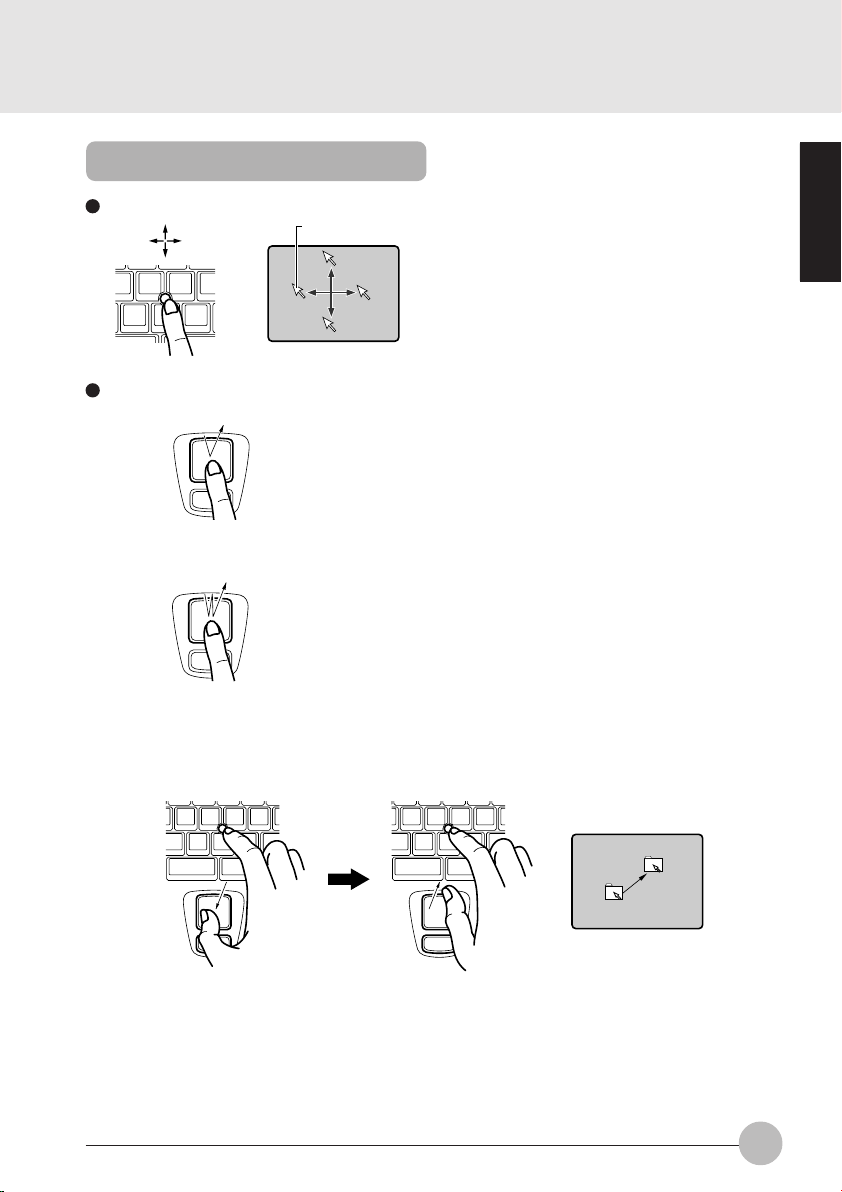
Quick Point IV Usage
Manner to operate the stick The small arrow (mouse pointer) on the screen
Manner to press the button
• Click
• Double click
• Drag To “drag” the selected objective across the screen,
moves as you move the stick with a fingertip. Move
the stick to and fro, and to the right and left to see
how the pointer moves on the screen.
“Click” refers to tapping on the upper button once,
pressing it down and then immediately releasing
it.
“Right click” refers to tapping on the lower button
once.
Press the upper button twice until it clicks, then
immediately release it.
move the stick while holding down the upper
button and release the button in the desired
position.
SECTION 1
11
Page 18
SECTION 1
3. About the touch panel
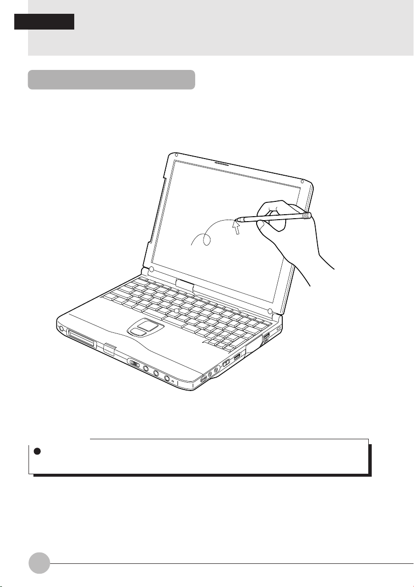
What is the touch panel?
The touch panel is a handy pointing device that enables you to directly control the mouse pointer on
the screen. The touch-sensitive panel covering the LCD screen can be operated with the pen which
comes with your personal computer. The touch panel which allows you to directly control objects on
the screen ensures intuitive and speedy computer operations.
The mouse pointer moves as you move the pen on the screen.
Critical Point
Always use the supplied pen to operate the touch panel. Using a finger or a ballpoint pen can
make the touch panel dirty or damage it.
12
Page 19
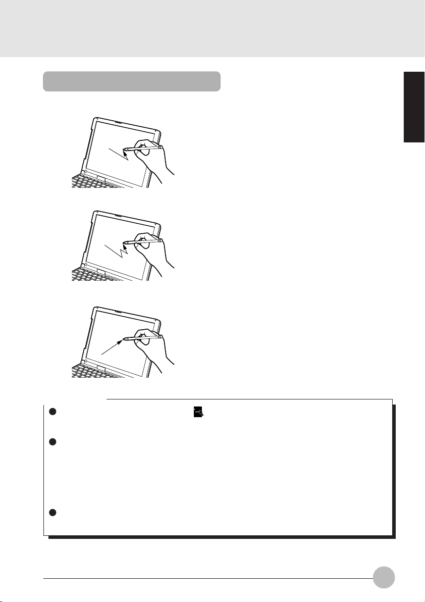
How to use the touch panel
• Single-click Tap on the screen once with the pen and move
it off the screen immediately.
• Double-click Tap on the screen twice in quick succession
with the pen and move it off the screen
immediately.
• Drag Move the pen while pressing it lightly against
the screen.
SECTION 1
Critical Point
To right-click on an object, press the [ ] key (application key) while pressing the pen lightly
against the desired object. Right clicking is effective only for right-clicking an icon; to rightclick on other objects on the screen, use the Quick Point IV.
Opening a sub-menu and choosing an icon require different ways of pointing (positioning the
mouse pointer over an object).
• To open a sub-menu:
Touch the desired menu item with the pen.
• To choose an icon:
Place the pen near the desired icon on the screen and drag the pen onto the icon to highlight
it.
The mouse pointer’s position can disagree with the point you touch with the pen after the
screen resolution is changed. In such a case, calibrate the effective area of the panel.
13
Page 20
Calibrating the touch panel
(Only for models with a touch panel)
If the mouse pointer’s position does not correspond to the point you touch with the pen, for
example, after the screen resolution is changed or the driver program is reinstalled, you need
to calibrate the effective area of the touch panel.
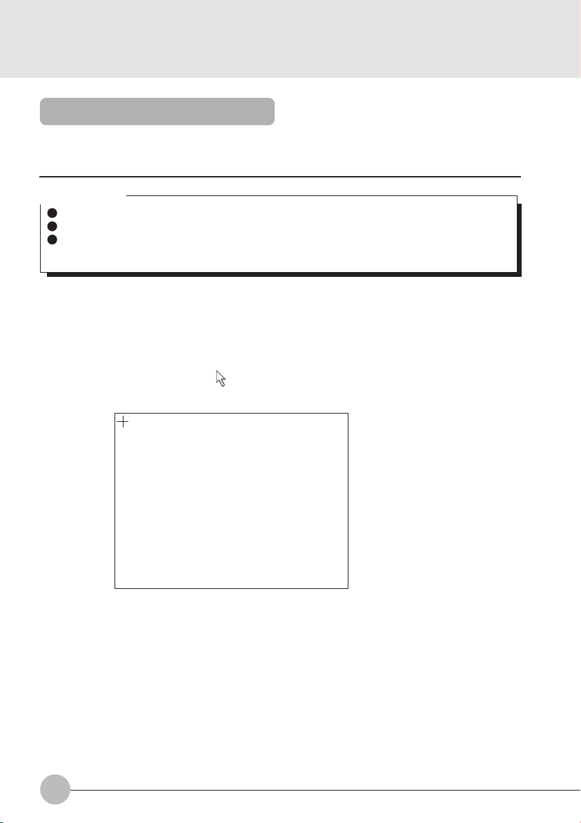
Critical Point
With the pen which comes with your computer, point to the red [+] mark on the screen.
Be careful not to touch the touch panel with a finger, etc. during operation.
The point you touch with the tip of the pen is recognized when you move the pen off the touch
panel.
1 Click on Start, Program, then Touch Panel Calibration.
The screen turns white, enabling you to calibrate the touch panel.
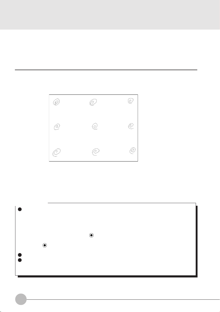
2 With the tip of the supplied pen, point to and touch the red [+] mark on the screen.
Point to the red [+] mark accurately because this mark acts as the datum for positioning.
You can hide the mouse pointer from view by pressing the Tab key.
Please touch nine red ‘+’ marks with the attached pen.
[Home]: Test Screen [Tab]: Cursor on/off [Arrow Keys]: moved ‘+’ marks
[Esc]: Cancel [Enter]: Next Screen
The [+] mark moves to the next position when you touch it.
14
Page 21
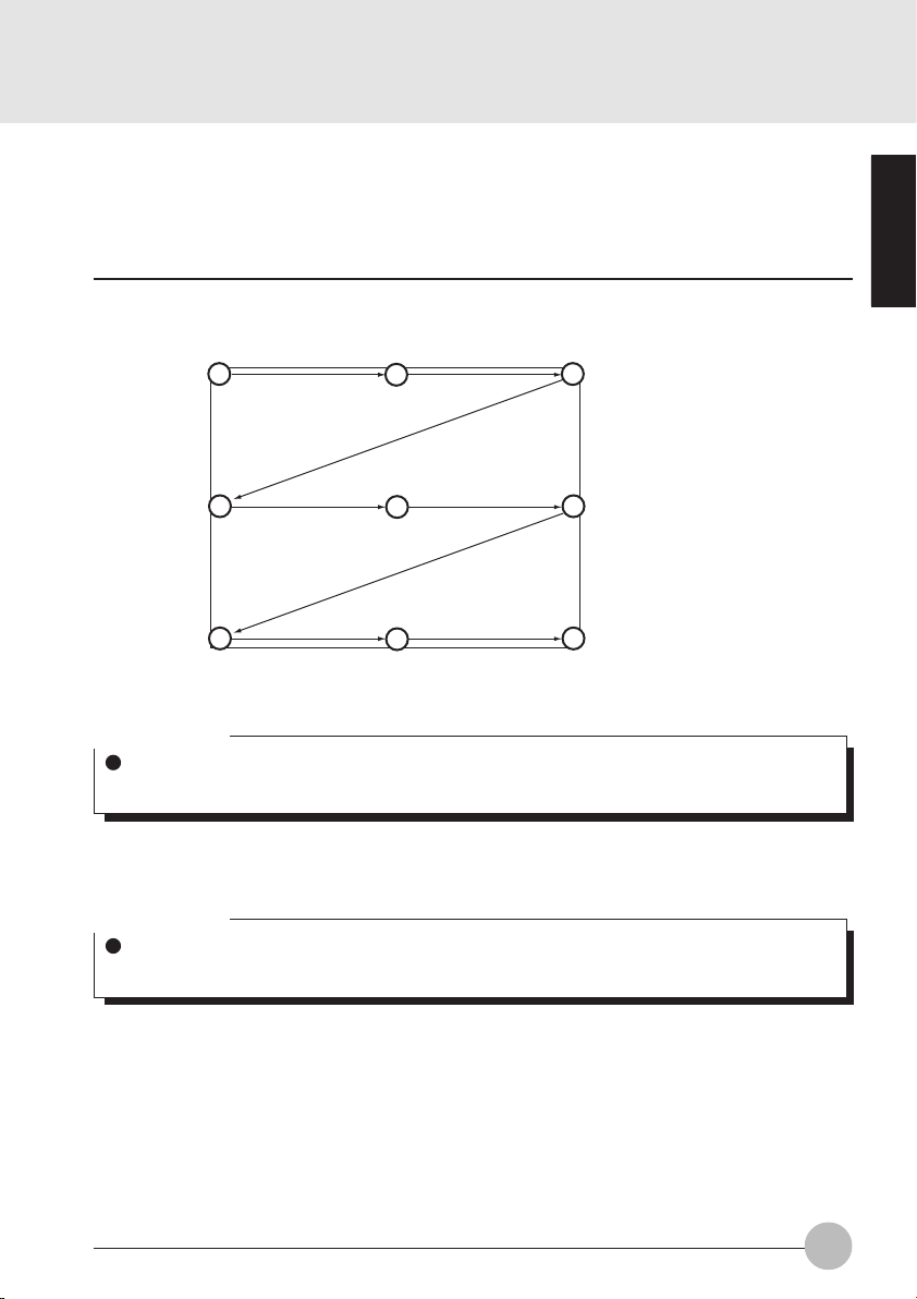
3 Similarly, touch the [+] mark in each position (a total of nine positions).
SECTION 1
–
–
Please touch nine red ‘+’ marks with the attached pen.
[Home]: Test Screen [Tab]: Cursor on/off [Arrow Keys]: moved ‘+’ marks
[Esc]: Cancel [Enter]: Next Screen
– +
+
+
+
+
+
Critical Point
If you touch the [+] mark in a position twice in quick succession, move the mark with arrow
keys [ ← ], [ → ], [ ↓ ] and [ ↑ ], then touch it once again.
4 Press the Enter key.
A window appears on the screen to show the calibration result.
Critical Point
If the message “Correction Parameter Error” is displayed, click on OK and repeat the above
steps 2 though 4 once again.
15
Page 22
5 Slide the pen in each of the four corners and at the center of the screen to check if the
touch panel is calibrated correctly.
6 After calibrating the touch panel correctly, press the Enter key.
7 The Touch Panel Calibration program exits.
The touch panel is now calibrated correctly.
Critical Point
The mode of clicking of your computer is set by default at “Single-click to select and doubleclick to open”. If you wish to change it to “Point to select and single-click to open”, then follow
the procedure below.
1 Double-click on the My Computer icon.
2 Click on Folder Option in the View menu.
3 Check Custom to enable it ( ), then click on Limited.
4 In the Mode of Clicking dialog, check “Point to select and single-click to open” to enable
it ( ), and then click on OK.
5 Close all the dialog boxes and windows.
The touch panel does not support right-clicking.
The touch panel calibrating method described in this user’s guide is intended for models with
the Quick Point IV. For other models, therefore, the method of calibrating their touch panels
can be different from that described in this guide.
16
Page 23
SECTION 1
4. Keyboard
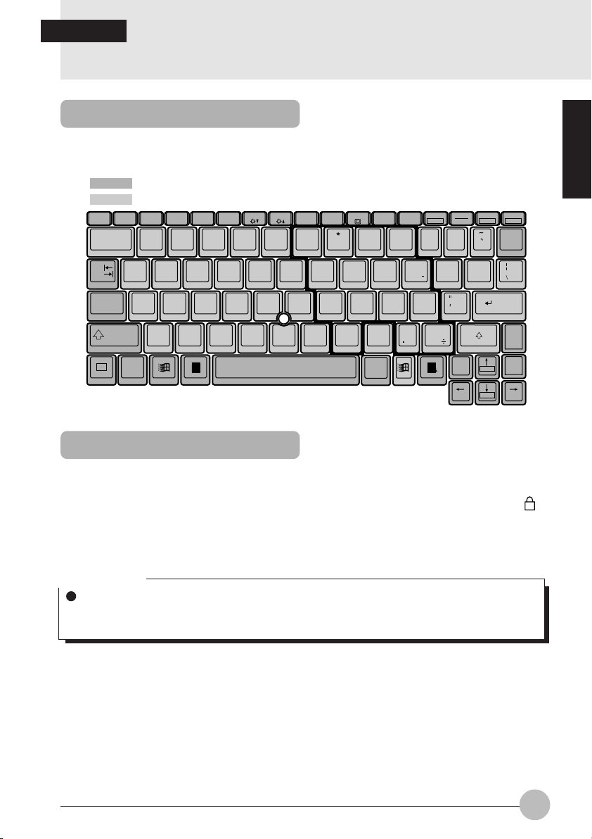
Keyboard
The keyboard is the device for giving instructions to the computer, inputting data, and executing. The
keys can be divided into two types.
: Control keys
: Character keys
F1
Esc
!
1
QWE
Tab
ASDFGHJ KL
Caps
Lock
Shift
Fn
Ctrl
F2 F3 F4 F5 F7 F8 F9 F10 F11F6
@
#
2
34
ZXCVBNM
%^5&
$
RTY
678
78
UI OP
456
1
0
NumLK
F12
(
)
9
0
9
x
2
3
<
>
,
.
Alt
Break
Scr LK
+
—
=
-
:
;
+
?
/
Ctrl
Del
Prt Sc
SysRq
Back
Space
}{
][
Enter
Page
Shift
Up
Page
Home
Down
End
Ins
Pause
Numeric Keypad Mode
The mode in which some of the character keys are used as numeric keys (with a key layout that
makes numeric input easier) instead of their normal functions is called numeric keypad mode. The
keyboard is switched to numeric keypad mode with [Num Lk]. (In numeric keypad mode, 1 is
displayed on the status indicator LCD.) The keys surrounded by thick lines in the diagram above
become the numeric keypad. The numbers input with these keys are printed in pink on the front of
each key.
Critical Point
When the separately sold numeric keypad is connected, if you press Num Lk to put the computer
into numeric keypad mode, the keys on the external numeric keypad are enabled, but the
numeric keypad section on the keyboard is disabled.
SECTION 1
17
Page 24

Names of the Main Keys and their Functions
[Esc] (escape) key
The usage is determined by the application software. It is often used to return to the previous
operation.
[F1-F12] (function) keys
The usage depends on the application software.
[Fn] key
A key unique to this computer; it has the following functions.
[Fn + F3] This switches ON/OFF of the speaker.
[Fn + F5] This selects whether or not to use the entire LCD screen for display in test
[Fn + F10] Rotates among the three display options: LCD only, CRT only, both LCD
Space key
Inputs a single space character.
(This is the long key with nothing written on it at the center of the front of the keyboard.)
[↑] [↓] [←] [→] (cursor) keys
Move the cursor.
[Enter] key
Also called the return key or the line feed key. This key inputs line feeds and executes command.
[Ctrl] key
Used in combination with other keys; its functions depend on the application software.
[Shift] key
Used in combination with other keys.
[Alt] key
Used in combination with other keys; its functions depend on the application software.
[Caps Lock] key
To lock the keyboard into caps mode, press this key together with the Shift key. Pressing this
key again ends caps mode.
When a pip sounds with this operation, the speaker is on. When nothing
sounds, the speaker is turned off.
mode.
and CRT.
18
Page 25

[Num Lk] (numerical lock) key
Press to put the computer into numeric keypad mode.
[Scr Lk] (scroll lock) key
Its functions depend on the application software.
[Prt Sc] (print screen) key
Press this key to make a hard copy of the screen.
[Pause] key
Press this key to pause the screen display.
[Break] key
Its functions depend on the application software.
[Ins] (insert) key
Press this key to insert a new character between characters. The new characters are entered
at the cursor position.
[Del] (delete) key
Press this key to delete a character. Pressing the Delete key and the Ctrl and Alt keys at the
same time resets this computer.
[Home] key
Press this key to move the cursor directly to the head of the row or the head of the document.
[End] key
Press this key to move the cursor directly to the end of the row or the end of the document.
[Pg Up] key
Press this key to switch to the previous screen.
[Pg Dn] key
Press this key to switch to the next screen.
[Back Space] key
Press this key to delete the character to the left of the cursor position.
[Sys Rq] (system request) key
When this key is supported by the application software, this key is used for such functions as
resetting the keyboard. Press this key together with the [Alt] key.
[ ] (Windows) key (only valid for Windows 98)
Press this key to display the Start menu.
[ ] (Application) key (only valid for Windows 98)
Press this key to display the shortcut menu for the selected item. This key has the same role
as the mouse right click.
SECTION 1
19
Page 26
SECTION 1
5. Switching on the Power
Switching on the power
This item explains the normal way to switch the computer main unit power on and off.
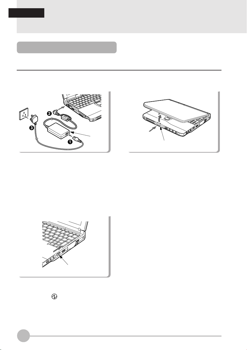
1 Connect the AC adaptor.
AC
adaptor
First connect the AC power cord to the AC
adaptor (1), next connect the other cord of
the AC adaptor to the personal computer’s DCIN connector (2). Lastly, plug the AC power
cord into an AC outlet (3).
3 Switch on the main switch of the
computer main unit.
2 Open the LCD panel.
latch
Push the latch to release the lock, then lift the
display panel with your hand.
Main switch
Power is supplied from the AC adaptor or the
battery, the power comes on, and the POST
starts. Also, the etc. on the status indicator
LCD are displayed.
20
Page 27
Critical Point
Do not carry this computer around or subject it to shock or vibration with the power on. These
can result in breakdown.
Column
POST is the abbreviation for POWER ON SELF TEST, which is a self-diagnostic test that
checks for abnormalities within the computer. This test is automatically carried out when the
power is switched on for this computer. If the power is switched off during the POST, an error
message is displayed the next time the computer is started up. Do not cut off the power
during the POST.
SECTION 1
21
Page 28
SECTION 1
6. Switching off the Power
This item explains how to switch off the power and gives precautions for switching off the
power.
Precautions when Switching Off the Power
The following precautions must be observed when switching off the power.
When switching off the main switch, end Windows 98 first.
When the main switch is switched off, if the suspend mode is suspend, the suspend function
stops working. If the application software has been suspended during execution, it is necessary
to save the data, then end the application software.
After you switch off the main switch, wait at least about ten seconds before switching it back
on again.
Switching Off the Power
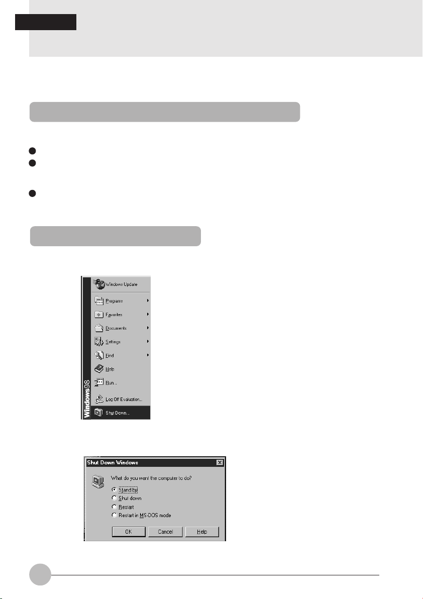
1 Click the Start button.
The Start menu is displayed.
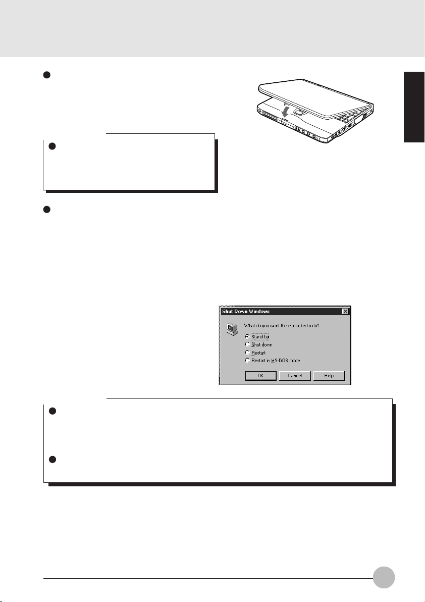
2 Click Shut Down.
The following message is displayed.
22
Page 29
3 Check that Shut down the computer is selected, then click Yes.
The power is switched off.
Critical Point
You can reset this computer by selecting Restart the computer with the screen shown in Step
2. Resetting means that the data in memory is all erased and the operating system is loaded
again from the hard disk or a floppy disk.
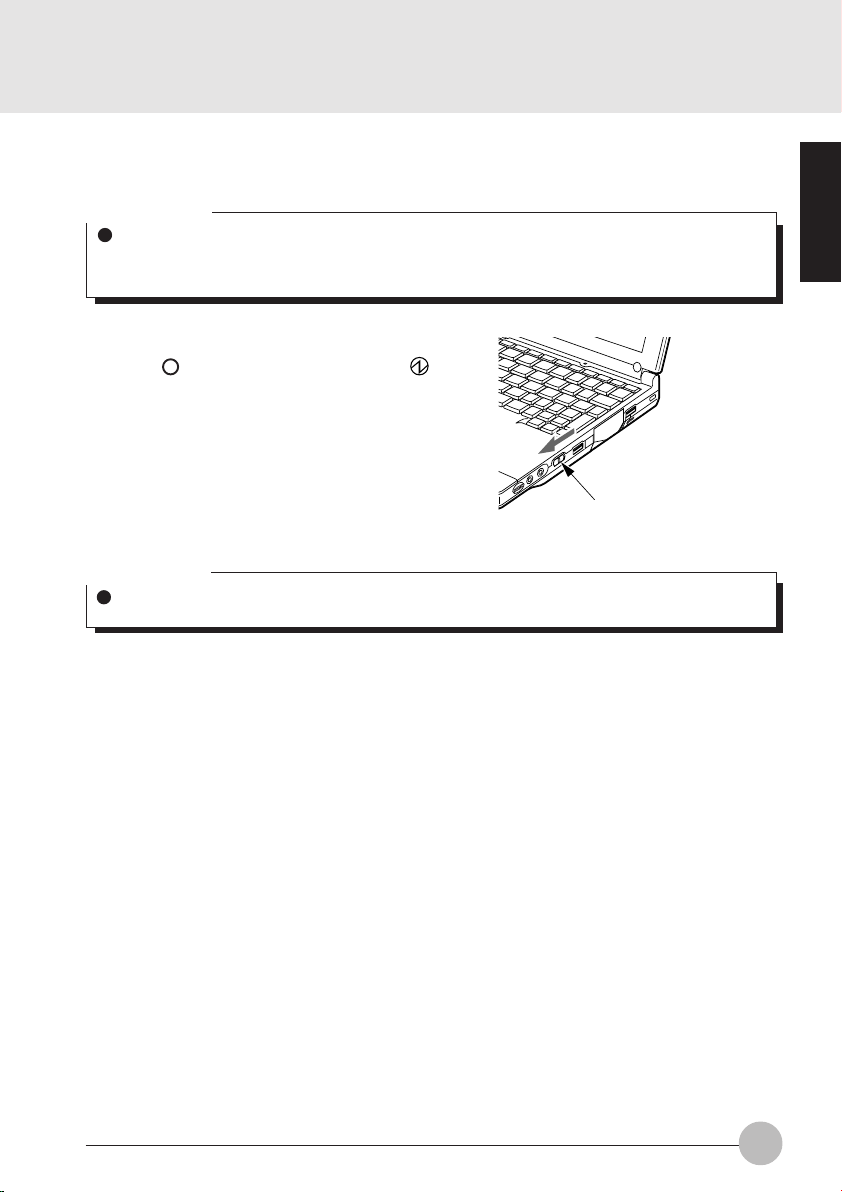
4 Switch off the main switch.
Slide the main switch in the direction of the
arrow ( side). The status indication LCD
indicator goes out and the power for the
computer main unit is cut off.
Main switch
Critical Point
If the computer will be unused for a long period, disconnect the AC adaptor.
SECTION 1
23
Page 30
SECTION 1
7. Suspend/Resume Function
What Is the Suspend/Resume Function?
When this computer is suspended with the SUS/RES switch, the suspend/resume function retains
the programs and data in memory as is so that you can resume operations immediately the next time
you press the SUS/RES switch.
Suspending
There are three ways to suspend this computer, using the SUS/RES switch, Cover close switch and
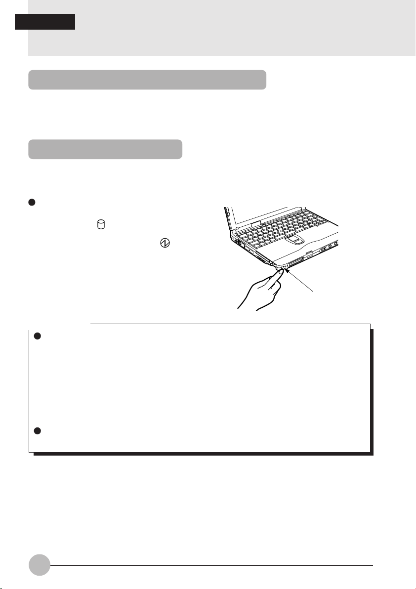
the Start menu.
Using the SUS/RES switch
1 Suspending
Check that is out. When you press the
SUS/RES switch, if the BIOS setup
suspend mode is suspend, flashes
and the computer goes into suspend
mode.
SUS/RES switch
Critical Point
Which of the two destinations suspending saves the data in the computer to depends on the
BIOS setup Power menu setting as follows.
System RAM:
When “Suspend” is set with the BIOS setup Power menu Suspend Mode item, the
data is saved to system RAM. Power for the system RAM is supplied from the AC
power supply if the AC adaptor is connected or from the battery if the AC adaptor is
not connected.
Save to Disk area:
If “Save to Disk” is set with the BIOS setup Power menu Suspend Mode item, the data
is written to the Save to Disk area on the hard disk.
If you hold down the Fn key while pressing the SUS/RES switch, the data is saved to the hard
disk regardless of the Power menu setting.
24
Page 31
Using the cover close switch
1 Close the LCD panel.
This unit goes into suspend mode using
the cover close switch.
Critical Point
When the BIOS setup Lid Closure Suspend
setting is “Disabled”, this unit does not go
into suspend mode even if you close the
LCD panel.
Use the [Quit Windows] dialog.
1 Click the [START] button and then click
the [Quit Windows].
The [Quit Windows] dialog appears on the
display.
2 Click [Standby].
This computer is suspended.
Critical Point
If the BIOS setup Suspend Mode setting is “Suspend”, suspend mode is ended in the following cases. Save important data to the hard disk, etc.
• The main switch is switched off.
• In battery operation, the battery runs out.
(The battery is still used in suspend mode.)
If you start with the internal battery fully charged, suspend mode lasts about one day maximum with the AC adaptor not connected.
SECTION 1
25
Page 32

Precautions for Suspending
Pay attention to the following points when using the suspend function.
When the computer is connected to a network using a LAN card or modem and when the
peripheral equipment is expanded with a PC card, you may not be able to use the suspend/
resume function. When you have expanded functions with a PC card, also check the manual
for the cards you are using.
Do not operate the SUS/RES switch when using Windows NT.
In the following cases, do not use the suspend function, but switch on/off the computer main
unit power supply with the main switch.
• When this computer is unused for a long period
When this computer will be unused longer than the effective period (about one day maximum)
for battery power for suspend mode, save all data, close Windows 98, then switch off the
main switch. If you suspend with the BIOS setup Suspend Mode set to Save to Disk, the
power goes off with the main switch still on. In this case, it does not matter if you switch off
the main switch. The next time you switch on the main switch, operation resumes.
• When installing or removing options
There are some options that can be installed without switching off the main switch. See
SECTION 2 of this manual and the manual that comes with the option product.
Critical Point
The SUS/RES switch does not work in the following cases.
• When the main switch is off
• When the battery has run out
• When the BIOS setup SUS/RES Switch is set to disabled
26
Page 33

Resuming
This personal computer can be resumed by the SUS/RES switch or the cover close switch.
Critical Point
When resuming this personal computer after it was suspended, resume it 10 or more seconds
after the last suspending operation.
The screen occasionally flickers during suspending/resuming operation.
Resuming with the SUS/RES switch.
1 Press the SUS/RES switch for resuming
the personal computer.
As the SUS/RES switch is pressed, the
mark of the status indicator LCD stops
blinking and continues lighting. This
indicates that the personal computer is in
the operating status.
SUS/RES switch
Resuming with the cover close switch.
1 Fold out the LCD display.
The personal computer is resumed by the
cover close switch.
Critical Point
When the Lid Open Resume of the BIOS
setup is set to “Disabled”, the personal
computer won’t be resumed by folding out
the LCD display.
Latch
SECTION 1
27
Page 34

SECTION 1
8. Battery
Battery Charging
For portability, this computer can operate either from the AC adaptor or from its battery.
This item explains how to charge the battery.
1 Connect the AC adaptor.
AC adaptor
First connect the AC power cord to the AC
adaptor (1), next connect the other cord of
the AC adaptor to the personal computer’s
DC-IN connector (2). Lastly, plug the AC
power cord into an AC outlet (3).
Relationship between computer modes and battery charging time
Main switch
ON
OFF
SUS/RES switch
Resume
Suspend
—
Computer mode
Operating mode
Suspend mode
Stopped
2 is displayed.
During charging, is displayed on the status indicator LCD and the remaining battery
charge is displayed.
Charging mode
Standard charging
Quick charge About 2.5 hours
Charging time
About 4.5 hours
Critical Point
When the battery charging indicator ( ) goes out and the remaining battery charge indicator
at the leftmost end changes its mode from blinking ( ) to continuous lighting ( ),
charging the battery is complete.
The battery capacity falls if the ambient temperature is too low or too high. We recommend
charging in the range 10°C-30°C.
When the expansion battery pack is charged, the built-in battery pack is charged together
with it.
28
Page 35

Battery Operation
This item explains operation with the battery.
1 Disconnect the AC adaptor and
switch on the main switch.
Main switch
Slide the main switch in the direction of the
arrow ( side).
is displayed.
2 When the MAIN switch is on, press
the SUS/RES switch.
SUS/RES switch
stops flashing and stays lit up.
Critical Point
When the ambient temperature is lower, the battery operating time is reduced. We recommend
that you use the battery within the range from 5°C to 35°C.
With this computer, the battery operating time depends on the conditions under which the
battery is used. However, the operating time of a new, fully-charged battery is as follows.
Only Internal Battery: about 1.5 to 3.0 hours
Conditions: Main unit only, full charge, with power management on. (The battery operating
time depends on the conditions of use.)
SECTION 1
29
Page 36

Checking the Remaining Battery Charge
This computer indicates the amount of battery charge remaining with the remaining battery
charge indicator on the status indicator LCD.
Remaining battery charge indicator
Indicates battery charge level of about 76% to about 100%
Indicates battery charge level of about 51% to about 75%
Indicates battery charge level of about 26% to about 50%
Indicates battery charge level of about 16% to about 25%
Indicates the low battery state (battery charge level of about 15% or lower).
The warning beeps and flashes.
Indicates that the battery has run out (0% charge level).
Critical Point
Indication of the remaining battery charge indicator ( ) may be slightly different from the
real remaining charge rate depending on the operating environment (temperature, number of
times that the battery was previously charged and discharged, etc.) because of the
characteristic of the battery (lithium ionic battery). In charging the battery, keep it in mind that
the battery is incompletely charged when the battery charging indicator ( ) is still on
though the remaining battery charge indicator indicates the full charge level ( ).
When the battery charge remains at a rate of 90 % or more, the battery cannot be recharged.
The battery can be recharged when its remaining charge is at a rate of 89 % or less.
Battery abnormality indicator
Indicates that the battery can not be charged normally.
Critical Point
When is displayed, take out the battery pack and re-install it. If this display still remains,
the battery pack is abnormal, so replace it.
30
Page 37

Low Battery State
This item explains the display when this computer’s battery is low and what to do.
1 The low battery is announced in the following way.
The warning beeps and the battery mark on the status indicator LCD flashes.
Critical Point
If the audio volume is set too low, you may not be able to hear the warning beep.
2 Press the SUS/RES switch.
When the battery goes low, quickly press the SUS/RES switch to suspend operation. Since
the suspend/resume function works even if the computer is suspended during operation, the
program and data are not lost.
Critical Point
If you want to resume operation immediately, connect the AC adaptor, then press the SUS/
RES switch again.
3 Charge the battery.
Connect the AC battery to charge the battery.
Critical Point
Reading from and writing to the hard disk uses large amounts of power. When saving data to
the hard disk with the battery low, connect the AC adaptor.
If you leave this computer running with the battery low, it is suspended automatically. However,
if data is being read from or written to the hard disk or other media, the suspending waits until
that processing is complete.
If you continue using the computer with the battery low, in the worst case, the data being
created or saved may be lost. Quickly connect the AC adaptor.
SECTION 1
31
Page 38

Replacing the Internal Battery Pack
Save the program to the hard disk or a floppy disk before replacing the internal battery pack.
This item explains how to replace the internal battery pack.
WARNING
ELECTRIC SHOCK
Always turn off the computer main unit main switch and disconnect the AC adaptor
before installing/removing the internal battery pack in order to avoid electric shock.
CAUTION
INJURY
Do not remove screws from any places other than those indicated in the manual when
installing/removing the internal battery pack.
There is a risk of injury or malfunction if you remove screws from places not indicated.
1 Turn the main switch off and discon-
nect the AC adaptor.
Main switch
Slide the main switch in the direction of the
arrow (to the side).
Disconnect the AC adaptor from the computer main unit.
32
2 Take out the internal battery pack.
Raise the two latches on the internal battery
pack while holding them, and remove the internal battery pack.
Page 39

3 Install the new internal battery pack.
Connect the connector of the new internal
battery pack to the connector of your personal
computer, and then insert and latch the battery
pack.
SECTION 1
33
Page 40

Precautions for Battery Pack
WARNING
ELECTRIC SHOCK
All battery packs are extremely delicate products. When installing or removing one, do
not drop it or subject it to strong shocks. If this should happen, do not use that battery
pack in the interest of safely, because there is a risk of electric shock or malfunction.
Discharge
• After you charge the battery pack, even if you store it without using it, over about 1 month it
will naturally discharge.
Service life
• The battery pack is a consumption item. After you use it for a long time, its charging capacity
drops.
• Replace the battery after about 300 to 500 charge/discharge cycles.
• When the battery operating time becomes extremely short, the battery has reached the end
of its service life.
To extend the battery operating time
Use the BIOS setup Power menu.
Conditions under which the battery operating time becomes shorter
• Using in cold or hot location
The battery operating time is influenced by the environmental temperature and the battery
operating time can be shorter at low temperature (5°C) than at high temperature (35°C).
Also, high temperatures not only lower the charging efficiency, but are also a cause of battery
pack deterioration.
• When the battery charging capacity drops
When the battery pack has been used for a long time, its charging capacity drops. In this
case, replace it with a new battery pack.
Use the AC adaptor in the following cases
• When using the hard disk or CD-ROM frequently
• When using a LAN or a Modem
34
Page 41

SECTION 1
9. Connector Box
Connecting the Connector Box
The following explains how to connect the connector box to the personal computer.
WARNING
ELECTRIC SHOCK
When connecting the connector
box to the personal computer, be
sure to turn off the MAIN switch of
the personal computer and
disconnect the AC adaptor from it
beforehand. If the connector box is
connected as the personal
computer is on, it may cause an
electric shock or a machine failure.
1 Turn off the MAIN switch of the
personal computer and disconnect
the AC adaptor from it.
Main switch
Slide the MAIN switch in the direction of the
arrow (toward side).
Disconnect the AC adaptor from the personal
computer.
SECTION 1
2 Connect the connector box to the
personal computer.
Open the cover of the connector box connector
located on the rear side of the personal
computer, and tightly connect the connector
box to the personal computer by their
respective connectors.
3 Lock the connector box by turning
the knob screws.
Knob screw
Tighten the right and left knob screws evenly
to lock the connector box.
35
Page 42

Disconnecting the Connector Box
The following explains how to disconnect the connector box from the personal computer.
WARNING
ELECTRIC SHOCK
When disconnecting the connector
box from the personal computer, be
sure to turn off the MAIN switch of
the personal computer and
disconnect the AC adapter from it
beforehand. If the connector box is
disconnected as the personal
computer is on, it may cause an
electric shock.
2 Loosen the right and left knob
screws to unlock the connector box.
1 Turn off the MAIN switch of the per-
sonal computer and disconnect the
AC adaptor from it.
Main switch
Slide the MAIN switch in the direction of the
arrow (toward side).
Disconnect the AC adaptor from the personal
computer.
3 Disconnect the connector box from
the personal computer.
3
Knob screw
36
1
Raise the connector box release lever and
detach the connector box. After this, close
connector cover.
2
Page 43

SECTION 1
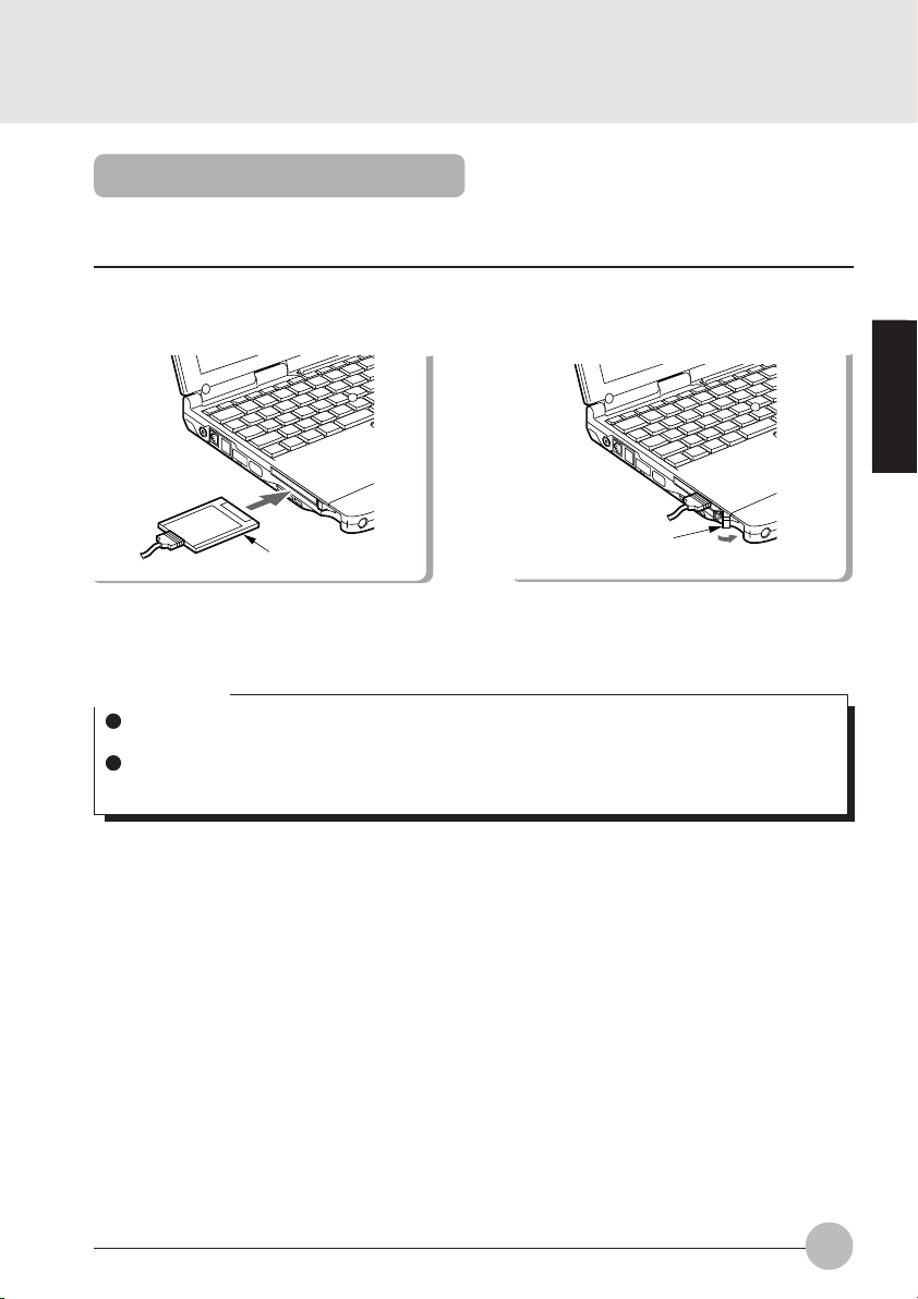
10. Built-in LAN (local-area network) device
This item explains how to connect a LAN cable into the LAN connector.
Connection
WARNING
ELECTRIC SHOCK
Be sure to turn off your personal computer and disconnect the AC adaptor from it before
connecting a LAN cable to the computer, otherwise you might get an electric shock.
ELECTRIC SHOCK
When it thunders in the neighbourhood, immediately turn off your personal computer
and disconnect the AC adaptor and the LAN cable from it, otherwise your computer
might be struck and damage by lightning and thus cause a fire.
CAUTION
ELECTRIC SHOCK
Do not touch the LAN connector with your finger, otherwise you might get an electric
shock.
1 Turn off the computer and disconnect the AC adaptor from it.
2 Plug a LAN cable into the LAN connector on your personal computer to connect it to a
network.
SECTION 1
Critical Point
To unplug the LAN cable from the LAN connector, pull the jack
while holding down the latch. Failure to do so might damage the
jack, cable or connector.
Your computer consumes more electric energy when it is connected
to a LAN. When using a LAN, therefore, it is advisable to use the
AC adaptor to supply power to your computer.
37
Page 44

SECTION 1
11. Built-in FAX modem
This item explains how to plug a telephone cable into the modular connector.
Connection
WARNING
ELECTRIC SHOCK
Be sure to turn off your personal computer and disconnect the AC adaptor from it before
connecting a modular cable to the computer, otherwise you might get an electric shock.
ELECTRIC SHOCK
When it thunders in the neighbourhood, immediately turn off your personal computer
and disconnect the AC adaptor and the modular cable from the computer, otherwise
your computer might be struck and damage by lightning and thus cause a fire.
CAUTION
ELECTRIC SHOCK
Do not touch the modular connector with your finger, otherwise you might get an electric shock.
1 Turn off the computer and disconnect the AC
adaptor from it.
2 Using a telephone cable, connect the compu-
ter to the telephone line.
Critical Point
To disconnect the modular cable from the connector, pull the jack
while holding down the latch. Failure to do so might damage the
jack, cable or connector.
Your computer consumes more electric energy when using the
built-in modem. When using the modem, therefore, it is advisable
to use the AC adaptor to supply power to your computer.
CAUTION
The internal modem has a maximum speed of 56000bps by ITU-T V.90 standard. Its
maximum speed of 53000bps is the highest allowed by FCC, and its actual connection
rate depends on the line conditions. The maximum speed is 33600bps at upload.
CAUTION
The internal modem is not intended for use with Digital PBX systems. Do not connect
the internal modem to a digital PBX as it may cause serious damage to the internal
modem or your entire notebook.
Consult your PBX manufacturer’s documentation for details. Some hotels have digital
PBX systems.
Be sure to find out BEFORE you connect your modem.
38
Page 45

SECTIONSECTION
SECTION
SECTIONSECTION
SECTIONSECTION
SECTION
SECTIONSECTION
22
2
22
22
2
22
This section explains installation of
options for this computer.
SECTION 2
Page 46

SECTION 2
1. Options
Options
You can expand the functions of this computer by connecting various options.
Floppy
Disk Unit
Printer
IC memory
card
SCSI
card
LAN card
Connector Box
Expansion
RAM module
Mouse
CCD
Camera
Color CRT display
Numeric
key pad
40
Page 47
WARNING
ELECTRIC SHOCK
Only connect equipment recommended by Fujitsu.
Connecting any other equipment can cause electric shock, fire, or breakdown.
CAUTION
INJURY
When installing/removing options, do not remove any screws other than those specified
by this manual.
Removing any other screws can cause injury and breakdown.
BREAKDOWN
Read this manual carefully and connect cables correctly. If you use this computer with
cables connected incorrectly, this can cause breakdown of the computer main unit and
of the peripheral equipment.
SECTION 2
41
Page 48

SECTION 2
2. PC Cards
Precautions for PC Cards
Observe the following points when using PC cards to prevent breakdown.
Do not place PC cards in hightemperature locations and locations subject to direct sunlight.
Do not place heavy objects on
top of PC cards.
Do not subject PC cards to
strong shocks.
Be careful to avoid spilling coffee
and other liquids on PC cards.
Avoid rubbing PC cards and
building up static electricity.
When storing a PC card, always
place it in its special case.
42
Page 49
Installing PC Cards
PC card is a generic term for business card sized cards which have a program and data
memory function or peripheral equipment functions such as a modem or LAN adaptor.
This item explains how to install a PC card.
1 Install the PC card.
PC card
Insert the PC card into the PC card slot with
the product name facing upwards.
2 Tilt the PC card eject/lock button
down to lock the PC card.
PC card eject/lock
button
Pull out the PC card eject/lock button
completely and then tilt it down to lock the PC
card with the fastener.
Critical Point
For some PC cards, the main power switch should be turned off. Refer to the manual attached
to your PC card.
In order to avoid damage, be careful not to knock or put anything on top of the connection
point between the PC card and the cord.
SECTION 2
43
Page 50

Removing PC Cards
This item explains how to remove a PC card.
1 Click the PC card icon on the task bar.
A message is displayed for stopping the installed PC card.
2 Click the PC card to be removed.
The PC card operations stop and the following screen is displayed.
Critical Point
For IC memory cards, the “This device cannot be removed” message may appear. If this
message does appear, close Windows 98 and switch off the computer main unit power before
removing the IC memory card.
3 Click OK.
44
Page 51

4 Raise the PC card eject/lock button. 5 Remove the PC card.
PC card
PC card eject/
lock button
Press the PC card eject/lock button to eject
the PC card.
PC card eject/
lock button
Critical Point
Never remove a PC card by pulling on its cord. Twisting on the cord can break the PC card.
Always use the procedure above for removing PC cards. Removing PC cards in any other
way can cause breakdown.
SECTION 2
45
Page 52

SECTION 2
3. Expansion RAM Modules
Installing an Expansion RAM Module
This item explains how to install expansion RAM modules.
WARNING
ELECTRIC SHOCK
Always turn off the computer main
unit main switch and disconnect
the AC adaptor when installing an
expansion RAM module in order to
avoid electric shock.
2 Remove the cover of the expansion
RAM module slot.
1 Turn off the main switch and
disconnect the AC adaptor.
Main switch
Slide the main switch in the direction of the
arrow (to the side).
Disconnect the AC adaptor from the main unit.
3 Install the expansion RAM module.
Take out the screws on the bottom of the
computer main unit and remove the cover of
the expansion RAM module slot.
46
Align the notch of the expansion RAM module
with the projection on the connector, insert
firmly diagonally from above and push down
until the module clicks into place.
Page 53

4 Fit the cover of the expansion RAM
module slot.
Fit the cover removed in 2.
CAUTION
DAMAGE
The expansion RAM module is made up of parts that are extremely vulnerable to
static electricity and can be damaged by the static electricity built up in the body.
When installing or removing an expansion RAM module, hold it by the edges. Do not
touch any terminals or ICs. Also, do not touch any parts or terminals within the computer
main unit.
Checking expansion memory
To check the extended memory capacity after installing an expansion RAM module, look at the
DIMM item of the BIOS setup info menu. For example, when a 32 MB expansion RAM module
has been installed, “32 MB” is indicated in the DIMM item. If the memory capacity indicated in the
DIMM item is not increased after installing an expansion RAM module though it has correctly
been installed, it is possible that the RAM module is faulty or defective. In such the case, consult
with the store at which you purchased the RAM module about the trouble.
SECTION 2
47
Page 54

Removing an Expansion RAM Module
This item explains how to remove an expansion RAM module.
WARNING
ELECTRIC SHOCK
Always turn off the computer main
unit main switch and disconnect
the AC adaptor when removing an
expansion RAM module in order to
avoid electric shock.
2 Remove the cover of the expansion
RAM module slot.
1 Turn off the main switch and
disconnect the AC adaptor.
Main switch
Slide the main switch in the direction of the
arrow (to the side).
Disconnect the AC adaptor from the main unit.
3 Remove the expansion RAM module.
Remove the cover of the expansion RAM
module slot on the bottom of the computer
main unit.
48
Open the hooks on both sides that retain the
expansion RAM module to the left and right,
then remove the expansion RAM module from
the slot.
Page 55

4 Fit the cover of the expansion RAM
module slot.
Fit the cover removed in 2.
SECTION 2
49
Page 56

SECTION 2
4. Floppy Disk Unit
Installing a Floppy Disk Unit
The following explains the method to connect a floppy disk unit.
WARNING
ELECTRIC SHOCK
Always turn off the computer main
unit main switch and disconnect
the AC adaptor when installing or
removing a floppy disk unit in order
to avoid electric shock.
2 Connect the connector box to the rear
of the personal computer by their
respective connectors.
1 Turn off the main switch and
disconnect the AC adaptor.
Main switch
Slide the main switch in the direction of the
arrow (to the side).
Disconnect the AC adaptor from the main
unit.
3 Install the floppy disk unit.
50
Page 57

Precautions for Floppy Disk Units
Take the following precautions when using the floppy disk unit in order to prevent damaging
it.
Avoid storing the floppy disk unit in extremely hot and cold locations, or in locations subject to
severe temperature changes.
Keep the floppy disk unit out of direct sunlight and away from heating equipment.
Avoid storing the floppy disk unit in locations subject to shock or vibration.
Avoid using the floppy disk unit in damp or dusty locations.
Never use the floppy disk unit with any liquid, metal or other foreign matter inside it. If any foreign
matter gets inside the floppy disk unit, consult your local dealer.
Wipe the floppy disk unit clean with a dry soft cloth or with a soft cloth moistened with water or a
neutral detergent solution. Never use benzine, paint thinner or other volatile material.
Never disassemble or dismantle this product.
Critical Point
Use the floppy disk unit away from equipment that creates a magnetic field such as a CRT
monitor or an AC adaptor.
SECTION 2
51
Page 58

Removing a Floppy Disk Unit
This item explains how to remove a floppy disk unit.
WARNING
ELECTRIC SHOCK
Always turn off the computer main
unit main switch and disconnect
the AC adaptor when installing or
removing a floppy disk unit in order
to avoid electric shock.
2 Remove the floppy disk unit.
1 Turn off the main switch and
disconnect the AC adaptor.
Main switch
Slide the main switch in the direction of the
arrow (to the side).
Disconnect the AC adaptor from the main unit.
Critical Point
When you remove a connector, press both
sides of the connector and pull it. Pulling
a cable unnecessarily can cause damage.
52
Page 59

What is a Floppy Disk?
A floppy disk is a medium for storing programs or data. This item explains basic knowledge
and precautions regarding floppy disks.
Types of floppy disks
If floppy disks are classified according to the amount of data they can store (the memory capacity),
typically there are the following 2 types.
• 2HD floppy disks
These have 1.44MB (megabyte: unit of data
amount) and 1.2MB memory capacities.
• 2DD floppy disks
These have 720KB (kilobyte) memory capaci-
ties, half of the 2HDs.
The differences between the 2 kinds of floppy
disks are shown in the diagram on the right.
3 mode drive
This computer’s floppy disk drive is a 3 mode drive that can read 1.44MB, 1.2MB and 720KB
memory capacity floppy disks. Therefore it can read nearly all floppy disks. However, when exchanging data with another computer, you have to be careful if the other computer’s floppy disk
drive is not a 3 mode drive. For example, if the other computer can read 1.2MB floppy disks but
not 1.44MB floppy disks, you have to enter the data after putting it into 1.2MB format in advance
with this computer.
Critical Point
Some floppy disks cannot be read by this computer, depending on the floppy disk format.
HD mark or no mark
2HD 2DD
Hole or no hole
SECTION 2
53
Page 60
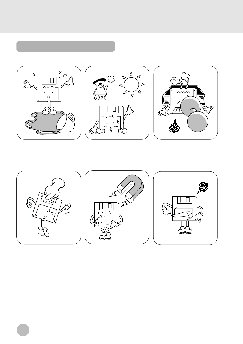
Precautions on Handling
Take the following precautions when using floppy disks in order to avoid damaging them.
Be careful not to spill liquids such
as coffee onto them.
Never touch the surface of the
disk.
Do not place them in places with
high temperatures or in direct
sunlight.
Do not bring them near to magnetic fields.
Do not bend them or place heavy
objects on top of them.
Do not stick labels on over each
other.
54
Page 61
Loading/Ejecting a Floppy Disk
This item explains how to load and eject floppy disks.
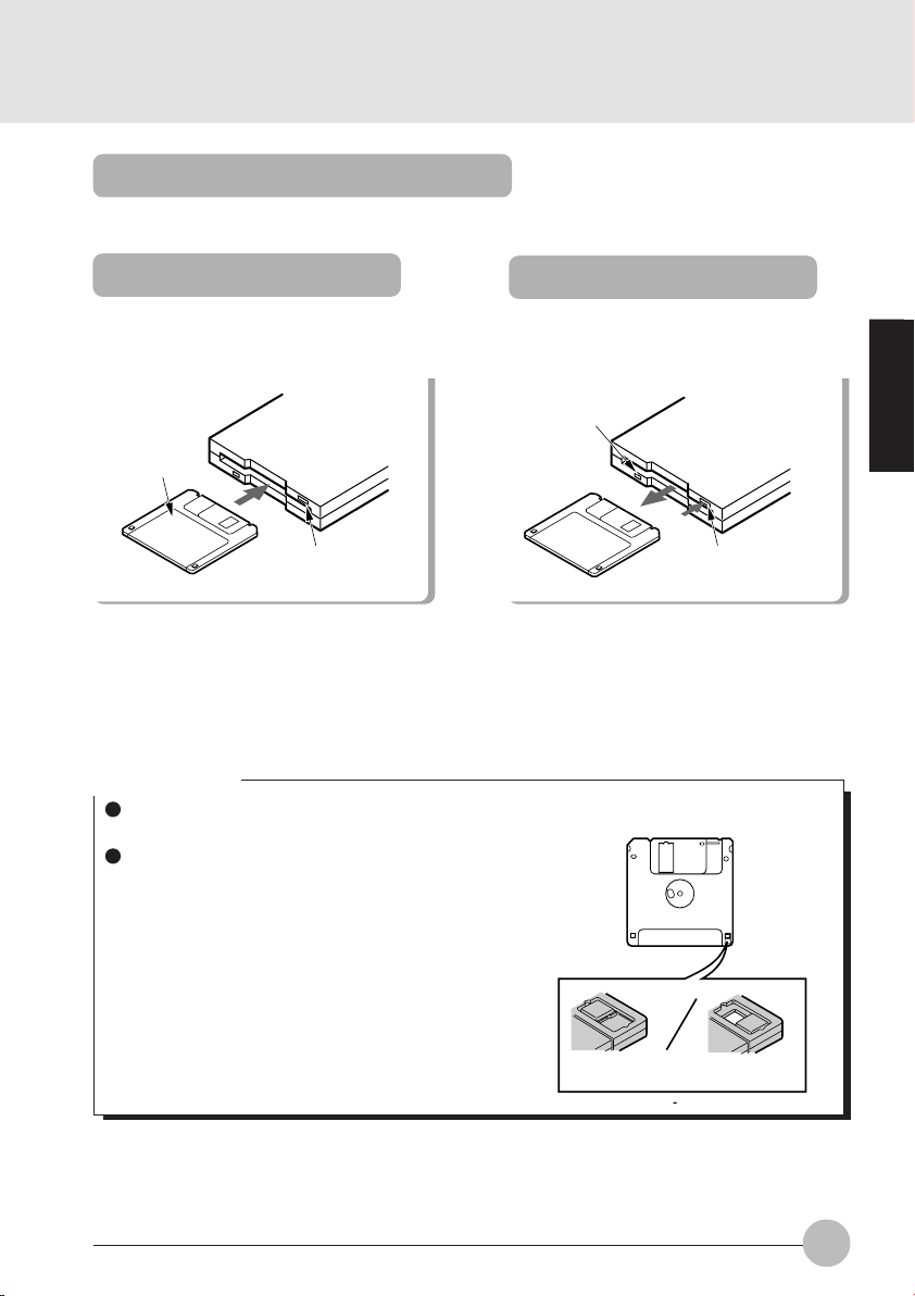
Loading
Insert into the floppy disk drive.
Floppy disk
EJECT button
Insert the floppy disk with the label upwards
and the shutter side first until the EJECT
button springs out.
Press the EJECT button.
Access lamp
Check that the floppy disk unit’s access lamp
is out, then press the EJECT button.
Ejecting
EJECT button
Critical Points
If you eject the floppy disk while the floppy disk unit’s access lamp is still on, there is a risk of
losing the data on the disk.
When you do not want to erase the data saved
on the disk, or when you do not want to write
additional data, slide the floppy disk’s write
protector so that the hole is open (WRITE
PROTECT state). When you want to write data
again, slide the write protector so that the hole
is closed.
Write protector
SECTION 2
WRITE ENABLE WRITE PROTECT
55
Page 62

SECTION 2
5. CCD Camera
Connecting a CCD Camera
This item explains how to connect a CCD camera.
* Depending on the model, a Fujitsu video capture software is preloaded into your computer.
To connect a CCD camera directly to the USB connector
1 Raise the tilt foot on the back of the CCD camera and slide the connector.
Keep holding the connector slide button (1) while sliding the connector (2).
2 Connect the CCD camera to your personal computer.
Fully engage the CCD camera connector and its hook with the USB connector and the jack
just under it on the back of your personal computer to fix them firmly.
56
Page 63

To connect a CCD camera, using a connecting cable
1 Connect the larger plug of the connecting cable to the CCD camera and the smaller
plug to your personal computer.
2 Fix the CCD camera to your personal computer.
Pull out the personal computer fixing tab from the CCD camera and fix the personal computer on
the top of the CCD camera.
SECTION 2
57
Page 64

SECTION 2
6. Mouse
Connecting a Mouse
This item explains how to connect a mouse.
1 Turn off the main switch of your
personal computer and attach the
connector box to it.
Main switch
Slide the main switch in the direction shown
by the arrow (toward ) to attach the
connector box.
2 Connect a mouse to the connector
box.
Have the arrow marked on the connector
facing up.
Critical Point
For using the mouse, select “Keyboard/Mouse Features” from the “Advanced Menu” of the
BIOS setup first, and then properly set the Pointing Device Configuration.
Using the Mouse
Moving the Mouse.
Place your hand on the mouse so that your fingers are resting on the left and right buttons and
move the mouse by sliding it over your desktop or other smooth surface. The arrow (called the
mouse pointer) on the screen moves in the same way as the mouse. Try moving the mouse while
watching the screen.
58
Page 65

Button operations
• Click
• Double click
• Pointing
Click
Click, click
Press the left mouse button once until it clicks.
The action of pressing the right button once firmly
enough that it clicks is called a “right click”.
Press the mouse left button two times quickly in
a row.
Align the mouse pointer with a menu item. When
there is another level for the menu item the cursor is on (when > is displayed at the right of the
menu item), that menu level is displayed.
SECTION 2
• Dragging
Release
Press
Move the mouse pointer with the mouse left button held down, then release the button at the
desired position.
59
Page 66

SECTION 2
7. Numeric Keypad
Connecting a Numeric Keypad
This item explains how to connect a numeric keypad.
1 Switch off the main switch.
Main switch
Slide the main switch in the direction of the
arrow ( side).
Critical Point
When a mouse is connected to the numeric
keypad mouse connector, the mouse
connector on the computer main unit cannot
be used.
You can adjust the tilt of the numeric keypad
with the tilt feet on the bottom of the numeric
keypad.
2 Connect the numeric keypad.
Have the arrow marked on the connector facing up.
mouse connector
60
Page 67

SECTION 2
8. Printer
Connecting a Printer
This item explains how to connect a printer.
WARNING
ELECTRIC SHOCK
Always switch off the computer main unit main switch and disconnect the AC adaptor
before connecting/disconnecting a printer. Connecting/disconnecting a printer with the
power on can cause electric shock.
CAUTION
BREAKDOWN
When connecting cables, read this manual carefully and make sure to connect correctly.
Using this computer with cables incorrectly connected can cause breakdown of the
computer main unit and the printer.
Critical Point
Connecting a printer requires a printer cable. Sometimes this cable does not come with the
printer. Even if the printer cable does come with the printer, sometimes it has the wrong
configuration for this computer. In either of these cases, separately purchase a printer cable
that you can connect to this computer.
How to connect the printer depends on the printer. For details, refer to the printer manual.
SECTION 2
61
Page 68

1 Switch off the main switch and
disconnect the AC adaptor.
Main switch
Slide the main switch in the direction of the
arrow ( side). Disconnect the AC adaptor.
3 Connect the printer to the computer main unit.
Connect the printer cable between the connector box’s parallel connector and the printer’s
connector, and then fix it securely with screws and fixtures.
2 Connect the connector box to the
rear of the personal computer by
their respective connectors.
4 Connect the printer’s power cord and switch on its power.
5 Connect the AC adaptor to the computer main unit and switch on main switch.
6 Make the printer settings.
62
Page 69

SECTION 2
9. CRT Monitor
Connecting an External CRT Monitor
An external CRT monitor can be connected to this computer. This item explains how to connect
a CRT monitor to the CRT connector on the right of the computer main unit.
WARNING
ELECTRIC SHOCK
Always switch off the computer main unit main switch and disconnect the AC adaptor
before connecting/disconnecting a CRT monitor. Connecting/disconnecting a CRT
monitor with the power on can cause electric shock.
CAUTION
BREAKDOWN
When connecting cables, read this manual carefully and make sure to connect correctly. Using this computer with cables incorrectly connected can cause breakdown of
the computer main unit and the CRT monitor.
1 Switch off the main switch and disconnect the AC adaptor.
Slide the main switch in the direction of the arrow ( side).
Disconnect the AC adaptor.
SECTION 2
Main switch
63
Page 70

2 Connect the CRT monitor to the computer main unit.
Connect the CRT cable between the personal computer’s CRT connector and the CRT monitor’s
connector, and then fix it securely with screws and fixtures.
3 Connect the CRT monitor’s power cord and switch on its power.
4 Connect the AC adaptor to the computer main unit and switch on main switch.
5 Switch the screen display.
When you press Fn + F10, the display switches to the next step in the sequence:
LCD → simultaneous display → CRT → LCD.
64
Page 71

SECTION 2
8. One Touch Operation buttons
The one touch operation buttons function as quick access for pre-configured applications, browser or
e-mail. It enables users to start a program quickly with a single press on the buttons.
Lock A Internet E-Mail
1 2 3 4 5
1 Lock
When this button is set to lock location, all one-touch operation buttons are locked or disabled to
prevent careless operation.
2 A
Start an application. Press the button to start an application.
SECTION 2
3 Internet
Press this button to start your default browser.
4 E-mail
Press this button to launch your email program.
5 E-mail arrival indicator lamp.
This lamp indicates e-mail status :
• Turned on : Checking new arrival of e-mail
• Blinking : Newly arriving e-mail is recognized
• Turned off: No new mail
Critical Point
The one-touch operation buttons cannot be used in the following cases.
The MAIN switch is set at the OFF position (slid to the “ ” side).
65
Page 72

Checking new arrival of E-mail
Press the E-mail button to check to see if there is new arrival of E-mail. New arrival of E-mail
can be checked even when the Windows 98 is shutdown.
Important note
When the MAIN switch is turned off (set at “ ” side), new arrival of E-mail cannot be checked
with the E-mail button.
For operating the E-mail button, set up the computer so as to access the Internet beforehand.
1 Connect the system to access your email software.
2 Make sure the lock button is at correct position.
3 Press the E-mail button.
When the E-mail button is pressed, the computer accesses the Internet to check to see if
there is new arrival of E-mail or not.
A while later, the Outlook Express is activated and newly arriving E-mail, if there is any, is
received by the computer.
30 seconds after the computer completes reception of new E-mail(s), it automatically
discontinues accessing the Internet.
Arrival of new E-mail can be checked with the E-mail arrival indicator lamp.
This function is convenient for checking arrival of new E-mail as the LCD panel is closed.
When the E-mail button is pressed, the E-mail arrival indicator lamp goes on and then blinks or goes
out to indicate arrival or non-arrival of E-mail as shown below.
Turned on: Checking new arrival of E-mail
Blinking: Newly arriving E-mail is recognized.
Turned off: No arrival of E-mail is recognized.
If the LCD panel is opened, the suspended computer is resumed, or the Outlook Express is quitted,
the E-mail arrival indication lamp goes out.
(accessing the Internet)
66
Page 73

SECTIONSECTION
SECTION
SECTIONSECTION
SECTIONSECTION
SECTION
SECTIONSECTION
33
3
33
33
3
33
This section explains the BIOS
setup program, which is necessary
for setting the date and time and
power conservation mode. This
section also explains how to set the
password for protecting data in this
computer.
SECTION 3
Page 74

SECTION 3
1. BIOS setup
Snapshots of the BIOS setup screen and the possible setup options is shown in the following sections.
Underlined setup options show the default settings.
Columns between Selections and Note show the security level of each setup item. ‘S’ means
that the item needs the supervisor password security level and can not be changed with the
user password security level.
1.1 Main Menu
Main Advanced Security Power Boot Info Exit
System Time: [10:34:56]
System Date: [10/05/1999]
Floppy Disk A: [1.44/1.2 MB 3.5”]
:Primary Master: [Primary Master-(PM)]
Language: [English (US)]
F1 Help ↑↓ Select Item -/Space Change Value F9 Setup Defaults
ESCExit ←→ Select Menu Enter Select :Sub-Menu F10Save and Exit
PhoenixBIOS Setup Utility
Figure 1-1 Main menu
Item Specific Help
Adjust calendar clock
<Tab>, <Shift-Tab>, or
<Enter> selects field.
Setup Item
System Time
System Date
Floppy Diskette A
Primary Master
Language
68
Selections
00:00:00 to 23:59:59
01/01/1981 to
12/31/2099
Disabled
1.44/1.25 MB 3 1/2”
English (US)
xxxxxx (JP)
Table 1-1 Main menu options
Note (Item Specific Help)
Adjust calendar clock.
<Tab>, <Shift-Tab>, or <Enter> selects field.
Adjust calendar clock.
<Tab>, <Shift-Tab>, or <Enter> selects field.
Select floppy drive type. 1.44/1.25 MB 3 1/2 ”
S
is the valid value.
Selects floppy type. Note that 1.25 MB, 3 1/2”
references a 1024 byte/sector Japanese media
format.
Configure primary master ATA/ATAPI device.
Configures ATA/ATAPI device.
The default setting differs between US/
European model and Japanese model.
Select the display language for the BIOS.
Page 75
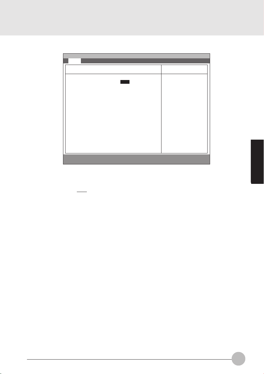
1.1.1 Main - Primary Master and Primary Slave Menu
Main Advanced Security Power Boot Info Exit
Primary Master [Hitachi_DK239A-65]
PhoenixBIOS Setup Utility
Item Specific Help
Setup Item
Type
Cylinders
Heads
Type: [Auto]
Cylinders: [12416]
Heads: [ 15 ]
Sectors: [ 63 ]
Maximum Capacity: 6007 MB
Multi-Sector Transfers: [16 Sectors]
LBA Mode Control: [Enabled]
PIO Transfer Mode: [Fast PIO 4]
DMA Transfer Mode: [Ultra DMA 2]
F1 Help ↑↓ Select Item -/Space Change Value F9 Setup Defaults
ESCExit ←→ Select Menu Enter Select :Sub-Menu F10Save and Exit
Select ATA/ATAPI
drive installed here.
[Auto]
The BIOS auto-type
the drive on boot
time.
Except [Auto]
You enter parameters
of the drive.
[None]
The drive is disabled.
Figure 1-2 Main - Primary Master and Primary Slave Menu
Selections
Auto
None
CD-ROM
ATAPI Removable
User
Note (Item Specific Help)
Select ATA/ATAPI device type. If ‘Auto’ is
selected, the type is automatically identified
at POST by the BIOS. It does not carry out
Cylinder/Head/Sector display in the case of
over 8.4GB-HDD when Auto mode. If ‘None’
is selected, all of the following setup items do
not appear. When ‘User’ is selected, you can
specify Cylinders, Heads and Sectors.
User = you enter parameters of hard-disk
drive installed at this connection.
Auto = autotypes ATA/ATAPI drive installed
here.
CD-ROM = a CD-ROM drive is installed here.
ATAPI Removable = removable disk drive is
installed here.
0 to 65535
This item appears when ‘Auto’ is selected and
S
the type is identified as hard disk, or ‘User’ is
selected. When ‘User’ is selected, you can
change the value.
Specify the number of Cylinders.
1 to 16
This item appears when ‘Auto’ is selected and
S
the type is identified as hard disk, or ‘User’ is
selected. When ‘User’ is selected, you can
change the value.
Specify the number of Heads.
SECTION 3
69
Page 76

Setup Item
Sectors
Maximum Capacity
Multi-Sector
Transfers
Selections
0 to 63
xxxx MB
Disabled
2 Sectors
4 Sectors
8 Sectors
16 Sectors
32 Sectors
64 Sectors
128 Sectors
Note (Item Specific Help)
This item appears when ‘Auto’ is selected and
S
the type is identified as hard disk, or ‘User’ is
selected. When ‘User’ is selected, you can
change the value.
Specify the number of Sectors.
Display maximum capacity calculated from
parameters of hard disk when ‘Auto’ is
selected and the type is identified as hard
disk, or ‘User’ is selected.
This option can not be changed when ‘Auto’
S
is selected.
Specify the number of sectors per block for
multiple sector transfer.
LBA Mode Control
PIO Transfer Mode
DMA Transfer Mode
Table 1-2 Main - Primary Master and Primary Slave Menu options
Disabled
Enabled
Standard
Fast PIO 1
Fast PIO 2
Fast PIO 3
Fast PIO 4
Disabled
Multiword DMA 1
Multiword DMA 2
Ultra DMA 0
Ultra DMA 1
Ultra DMA 2
This option can not be changed when ‘Auto’
S
is selected.
Enabling LBA causes Logical Block
Addressing to be used in place of Cylinders,
Heads & Sectors.
This option can not be changed when ‘Auto’
S
is selected. Multi-word DMA is automatically
set to mode 1 for ‘Fast PIO 1’, ‘Fast PIO 2’,
‘Fast PIO 3’ and set to mode 2 for ‘Fast PIO
4’.
Selects the method of moving data to/from
the drive. Autotype the drive to select the
optimum transfer mode.
You can not change this option when ‘Auto’ is
S
selected.
Selects the Ultra DMA mode used for moving
data to/from the drive. Autotype the drive to
select the optimum transfer mode.
70
Page 77

1.2 Advanced Menu
Setup Item
Plug & Play O/S
Protected Device
Configurations
Serial/Parallel Port
Configurations
Main Advanced Security Power Boot Info Exit
Plug & Play O/S [Yes]
Protected Device Configuration [No]
:Serial/Parallel Port Configurations
:Keyboard/Mouse Features
:Video Features
:Internal Devices Configurations
:PCI Configuration
:ACPI Feature
:Event Logging
F1 Help ↑↓ Select Item -/Space Change Value F9 Setup Defaults
ESCExit ←→ Select Menu Enter Select :Sub-Menu F10Save and Exit
PhoenixBIOS Setup Utility
Item Specific Help
[No]
The BIOS configures
also non-boot devices.
Select if you are
using a non-Plug &
Play OS or a non-ACPI
OS
[Yes]
The BIOS configures
only boot devices.
Figure 1-3 Advanced menu
Selections
No
Yes
Note (Item Specific Help)
Select ‘Yes’ if you are using a Plug & Play
S
capable operating system.
Select ‘No’ if you need the BIOS to configure
non-boot devices.
No
Ye s
‘Yes’ prevents a Plug and Play Operating
S
System from changing system settings.
Peripheral Configuration.
SECTION 3
Keyboard/Mouse
Features
Video Features
Internal Device
Configurations
PCI Configuration
ACPI Features
Event Logging
Setup keyboard/mouse features.
Configures display and video features.
Configures other internal devices.
Additional setup menus to configure PCI
devices.
Configure ACPI features.
Configure event logging features.
Table 1-3 Advanced menu options
71
Page 78

1.2.1 Advanced - Serial/Parallel Port Configuration Menu
Main Advanced Security Power Boot Info Exit
Serial/Parallel Port Configuration
PhoenixBIOS Setup Utility
Item Specific Help
Setup Item
Serial Port
I/O Address
Interrupt
Infrared Port
Mode
Serial port : [Enabled]
I/O Address: [3F8-3FF]
Interrupt: [IRQ 4]
Infrared Port : [Enabled]
Mode: [FIR]
I/O Address: [2E8-2EF]
Interrupt: [IRQ 3]
I/O Address: [118-11F]
DMA Channel: [DMA 3]
Parallel Port: [Enabled]
Mode: [Bi-directional]
I/O Address: [378-37F]
Interrupt: [IRQ 7]
F1 Help ↑↓ Select Item -/Space Change Value F9 Setup Defaults
ESCExit ←→ Select Menu Enter Select :Sub-Menu F10Save and Exit
[Disabled]
The port is disabled
[Enabled]
The port is enabled
with user
configuration
[Auto]
A Plug & Play OS or
an ACPI OS will
configure the port.
Figure 1-4 Advanced - Serial/Parallel Port Configuration Menu
Selections
Disabled
Enabled
Auto
Note (Item Specific Help)
S
Configure serial port A using options:
[Disabled] No configuration
[Enabled] User configuration
[Auto] BIOS or OS chooses configuration
3F8-3FF
2F8-2FF
3E8-3EF
S
This option is available when Serial port A is
‘Enabled’.
Set the base I/O address for serial port A.
2E8-2EF
IRQ 3
IRQ 4
IRQ 5
Disabled
Enabled
Auto
S
This option is available when Serial port A is
‘Enabled’.
Set the interrupt for serial port A.
S
Configure Infrared port using options:
[Disabled] No configuration
[Enabled] User configuration
[Auto] BIOS or OS chooses configuration
IrDA
FIR
S
Infrared port is ‘Enabled’.
Infrared port is ‘Disabled’.
I/O Address
72
3F8-3FF
2F8-2FF
3E8-3EF
2E8-2EF
S
Set the base I/O address.
Page 79

Setup Item
Interrupt
Base I/O address
Selections
IRQ 3
IRQ 4
IRQ 5
100-107
108-10F
110-117
118-11F
Note (Item Specific Help)
S
This option is available when Infrared port is
‘Enabled’.
Set the interrupt for Infrared port.
S
This option is available when Mode for Infrared
port is set to ‘FIR’.
Set the base I/O address for the FIR of
Infrared port.
DMA channel
Parallel port
Mode
I/O address
Interrupt
DMA 1
DMA 3
Disabled
Enabled
Auto
Output only
Bi-directional
ECP
378-37F
278-27F
3BC-3BF
IRQ 5
IRQ 7
Table 1-4 Advanced - Serial/Parallel Port Configuration Menu options
S
This option is available when Mode for Infrared
port is set to ‘FIR’.
Set the DMA channel for the FIR of Infrared
port.
S
Configure parallel port using options:
[Disabled] No configuration
[Enabled] User configuration
[Auto] BIOS or OS chooses configuration
S
This option is available when Parallel port is
‘Enabled’. When you change this mode to
‘ECP’, ‘DMA 1’ is selected by default.
Set the mode for the parallel port.
S
This option is available when Parallel port is
‘Enabled’.
Set the base I/O address for the parallel port.
S
This option is available when Serial port B is
‘Enabled’.
Set the interrupt for the parallel port.
SECTION 3
73
Page 80

1.2.2 Advanced - Keyboard/Mouse Features Menu
Main Advanced Security Power Boot Info Exit
Keyboard/Mouse Features
PhoenixBIOS Setup Utility
Item Specific Help
Setup Item
Numlock
Hot Plug
Pointing Device
Numlock: [Auto]
Hot Plug: [Enabled]
Pointing Device: [Configuration 1]
Touch Panel: Enabled
Quick Point: Enabled
External PS/2 Mouse: Disabled
F1 Help ↑↓ Select Item -/Space Change Value F9 Setup Defaults
ESCExit ←→ Select Menu Enter Select :Sub-Menu F10Save and Exit
Selects power-on
state for Numlock.
Figure 1-5 Advanced - Keyboard/Mouse Features menu
Selections
Auto
Note (Item Specific Help)
S
Selects Power-on state for Numlock.
On
Off
Disabled
S
Select Hot Plug.
Enabled
Configuration 1
Configuration 2
Configuration 3
Configuration 4
S
Select pointing device configurations.
Enabled
The pointing device is enabled.
Disabled
The pointing device is disabled.
Exclusive Enabled
The pointing device is enabled. However the
pointing device is disabled when an external
mouse PS/2 mouse is connected.
Table 1-5 Advanced - Keyboard/Mouse Features menu options
Pointing Device Configuration 1 Configuration 2 Configuration 3 Configuration 4
Touch Panel Enabled Enabled Disabled Disabled
Quick Point Enabled Disabled Enabled Exclusive Enabled
External PS/2 mouse Disabled Enabled Enabled Enabled
74
Page 81

1.2.3 Advanced - Video Features Menu
Main Advanced Security Power Boot Info Exit
PhoenixBIOS Setup Utility
Video Features
Item Specific Help
Setup Item
Display
Compensation
Display: [Internal Flat Panel]
Compensation: [Disabled]
F1 Help ↑↓ Select Item -/Space Change Value F9 Setup Defaults
ESCExit ←→ Select Menu Enter Select :Sub-Menu F10Save and Exit
Select display
terminal.
Figure 1-6 Advanced - Video Features menu
Selections
Internal Flat-Panel
Note (Item Specific Help)
Select display terminal.
External
Simultaneous
Disabled
Select compensation.
Enabled
Table 1-6 Advanced - Video Features menu
SECTION 3
75
Page 82

1.2.4 Advanced - Internal Device Configurations.
Main Advanced Security Power Boot Info Exit
Internal Device Configuration
PhoenixBIOS Setup Utility
Item Specific Help
Floppy Disk Controller: [Enabled]
IDE Controller: [Enabled]
LAN Controller [Auto]
F1 Help ↑↓ Select Item -/Space Change Value F9 Setup Defaults
ESCExit ←→ Select Menu Enter Select :Sub-Menu F10Save and Exit
Figure 1-6a Advanced - Internal Device Configurations
Setup Item
Floppy Disk Controller
IDE Controller
LAN Controller
Table 1-6a Advanced - Internal Device Configurations options
Selections
Disabled
Enabled
Disabled
Enabled
Auto
Disabled
Enabled
[Disabled]
Floppy Disk drive is
disabled.
[Enabled]
Floppy Disk drive is
enabled.
Note (Item Specific Help)
Enabled/Disable Floppy Drive.
Enabled/Disable IDE Controller.
Enabled/Disable LAN Controller.
When set to Auto mode With AC power
supply, the LAN device is always enabled.
With the battery, the device is enabled
only when the link is active.
76
Page 83

1.2.5 Advanced - PCI Configuration Menu
Main Advanced Security Power Boot Info Exit
PhoenixBIOS Setup Utility
PCI Configuration
Item Specific Help
Setup Item
IRQ Reservation
:IRQ Reservation
F1 Help ↑↓ Select Item -/Space Change Value F9 Setup Defaults
ESCExit ←→ Select Menu Enter Select :Sub-Menu F10Save and Exit
Reserve specific
IRQs for use by
legacy ISA devices.
Figure 1-7 Advanced - PCI Configuration menu
Selections Note (Item Specific Help)
Reserve specific IRQs for use by legacy ISA
devices.
Table 1-7 Advanced - PCI Configuration menu options
SECTION 3
77
Page 84
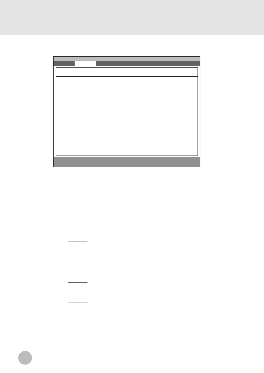
1.2.5.1 Advanced - PCI Configuration - IRQ Reservation Menu
Setup Item
IRQ 3
IRQ 4
IRQ 5
IRQ 7
IRQ 9
IRQ 10
Main Advanced Security Power Boot Info Exit
IRQ 3: [Available]
IRQ 4: [Available]
IRQ 5: [Available]
IRQ 7: [Available]
IRQ 9: [Available]
IRQ 10: [Available]
IRQ 11: [Available]
IRQ 15: [Available]
F1 Help ↑↓ Select Item -/Space Change Value F9 Setup Defaults
ESCExit ←→ Select Menu Enter Select :Sub-Menu F10Save and Exit
PhoenixBIOS Setup Utility
IRQ Reservation
Item Specific Help
Reserve the
specified IRQ for
use by legacy ISA
devices.
Figure 1-8 Advanced - PCI Configuration - IRQ Reservation menu
Selections
Available
Reserved
Note (Item Specific Help)
If [Reserved] is selected, the BIOS reserves
S
IRQ 3 for use by legacy ISA devices and does
not use it for embedded PCI or ISA devices.
IRQ 3 is removed from the IRQ bitmap in the
PCI IRQ routing table.
Reserve the specified IRQ for use by legacy
ISA devices.
Available
Reserved
Reserves IRQ 4.
S
Reserve the specified IRQ for use by legacy
ISA devices.
Available
Reserved
Reserves IRQ 5.
S
Reserve the specified IRQ for use by legacy
ISA devices.
Available
Reserved
Reserves IRQ 7.
S
Reserve the specified IRQ for use by legacy
ISA devices.
Available
Reserved
Reserves IRQ 9.
S
Reserve the specified IRQ for use by legacy
ISA devices.
Available
Reserved
Reserves IRQ 10.
Reserve the specified IRQ for use by legacy
ISA devices.
78
Page 85

Setup Item
IRQ 11
IRQ 15
Selections
Available
Reserved
Available
Reserved
Table 1-8 Advanced - PCI Configuration - IRQ Reservation menu options
Note (Item Specific Help)
Reserves IRQ 11.
S
Reserve the specified IRQ for use by legacy
ISA devices.
Reserves IRQ 15.
S
Reserve the specified IRQ for use by legacy
ISA devices.
SECTION 3
79
Page 86

1.2.5.2 Advanced - ACPI Features Menu
Main Advanced Security Power Boot Info Exit
PhoenixBIOS Setup Utility
ACPI Features
Item Specific Help
Setup Item
ACPI Management
ACPI Management: [Disabled]
F1 Help ↑↓ Select Item -/Space Change Value F9 Setup Defaults
ESCExit ←→ Select Menu Enter Select :Sub-Menu F10Save and Exit
Configures ACPI
Management feature.
[Disabled]
ACPI Management is
disabled.
[Enabled]
ACPI Management is
enabled.
Figure 1-7 Advanced - ACPI Features Menu
Selections
Enabled
Note (Item Specific Help)
Enabled/Disabled ACPI Management.
Disabled
Table 1-7 Advanced - ACPI Features Menu options
80
Page 87

1.2.6 Advanced - Event Logging Menu
Main Advanced Security Power Boot Info Exit
Event Log Capacity: Space Available
Event Log Validity: Valid
View Event Log: [Enter]
Event Logging: [Enabled]
Clear all event logs: [No]
Mark Events as Read: [Enter]
F1 Help ↑↓ Select Item -/Space Change Value F9 Setup Defaults
ESCExit ←→ Select Menu Enter Select :Sub-Menu F10Save and Exit
Setup Item
Event log capacity
Event log validity
View Event Log:
Event Logging
Clear all event logs
Mark Events as Read:
PhoenixBIOS Setup Utility
Event Logging
System Boot Event: [Disabled]
Item Specific Help
[No]
Event logs will not
be cleared at the
next boot.
[Yes]
All event logs will
be cleared at the
next boot. The value
is reset to [No]
after clearing logs.
Figure 1-10 Advanced - Event Logging menu
Selections
Note (Item Specific Help)
Display event log capacity.
Display event log validity.
[Enter]
Press Enter key to view the contents of the
event log.
Disabled
Enables Event Logging.
Enabled
‘Yes’ clears all DMI event logs at next boot.
No
The value is reset to ‘No’ after clearing logs.
Ye s
[Enter]
Press Enter key to mark all events currently
in the event log as read. Marked events will
not be displayed from the next “View Event
Log”.
SECTION 3
Table 1-10 Advanced - Event Logging menu options
81
Page 88

1.3 Security Menu
Main Advanced Security Power Boot Info Exit
Supervisor Password Is: Clear
User Password Is: Clear
Set Supervisor Password [Enter]
Set User Password [Enter]
Minimum User Password Length [0]
Password on Boot: [Disabled]
Password on Resume: [Disabled]
Boot from Removable Media: [All]
Floppy Disk Access: [All]
:Hard Disk Security
:Owner Information
Hard Disk Boot Sector: [Normal]
F1 Help ↑↓ Select Item -/Space Change Value F9 Setup Defaults
ESCExit ←→ Select Menu Enter Select :Sub-Menu F10Save and Exit
Setup Item
Supervisor Password Is
User Password Is
Set Supervisor Password
Set User Password
Floppy Disk Access
Password on Boot
Password on Resume
Hardisk boot
sector
PhoenixBIOS Setup Utility
Figure 1-11 Security menu
Selections
All
Supervisor Only
Disabled
Enabled
Disabled
Enabled
Normal
Write Protect
Item Specific Help
Press <Enter> key to
set Supervisor
Password to enable
any password
features.
Then password entry
is required to enter
BIOS Setup.
Note (Item Specific Help)
Display the setting of Supervisor password.
Display the setting of User password.
Supervisor Password controls access to the
S
setup utility.
User password can be set after Supervisor
password is set.
User Password controls access to the system
at boot.
This item can be set with Supervisor
S
password security level. When ‘Supervisor
Only’ is selected, floppy diskette drive is not
available with User password security level.
Controls access to diskette drives.
When Password on boot is ‘Enabled’, the
BIOS requires a password on OS boot.
Enables password entry on boot.
When Password on resume is ‘Enabled’, the
BIOS requires a password on resume.
Write protects boot sector on hard disk to
S
protect against viruses.
82
Page 89

Setup Item
Hardisk security
Selections
Note (Item Specific Help)
Primary Master
Disabled
Enabled
Table 1-11 Security menu options
1.3.1 Set Supervisor Password
Supervisor Password Is: Clear
Set Supervisor Password
Enter New Password [ ]
Confirm New Password [ ]
Supervisor Password Is: Set
Set Supervisor Password
Enter Current Password [ ]
Enter New Password [ ]
Confirm New Password [ ]
1.3.3 Security- Owner Information
Main Advanced Security Power Boot Info Exit
S
1.3.2 Set User Password
PhoenixBIOS Setup Utility
Owner Information
This item can be set with Supervisor
password security level. When ‘Enabled’ is
selected, the data of the hard disk are
protected with the password lock feature of
the drive. You can not read any data on the
drive if it is not installed in the same system
as it is locked with the password.
Enables fixed disk security.
User Password Is: Clear
Set User Password
Enter New Password [ ]
Confirm New Password [ ]
User Password Is: Set
Set User Password
Enter Current Password [ ]
Enter New Password [ ]
Confirm New Password [ ]
Item Specific Help
SECTION 3
Owner Information Is: Clear
Set Owner Information: [Enter]
Foreground Color: [Gray]
Background Color: [Black]
F1 Help ↑↓ Select Item -/Space Change Value F9 Setup Defaults
ESCExit ←→ Select Menu Enter Select :Sub-Menu F10Save and Exit
Figure 1-7 Security- Owner Information
83
Page 90

1.4 Power Menu
Main Advanced Security Power Boot Info Exit
Power Savings: [Customized]
Hard Disk Timeout: [Off]
Video Timeout: [Off]
Standby Timeout: [4 Minutes]
Auto Suspend Timeout: [15 Minutes]
Suspend Mode: [Suspend]
Auto Save To Disk: [Off]
Resume On Modem Ring: [Off]
Resume On Time: [Off]
Resume Time: [00:00:00]
:Advanced Features
F1 Help ↑↓ Select Item -/Space Change Value F9 Setup Defaults
ESCExit ←→ Select Menu Enter Select :Sub-Menu F10Save and Exit
PhoenixBIOS Setup Utility
Item Specific Help
Select Power
Management Mode.
Choosing modes
changes system power
management settings.
Maximum Power Savings
conserves the
greatest amount of
system power while
Maximum Performance
conserves power but
allows greatest
system performance.
To alter these
settings, choose
Customize. To turn
off power management,
choose Disable.
Figure 1-14 Power menu
Setup Item
Power Savings
Hard Disk Timeout
Display Timeout
84
Selections
Disabled
Customized
Maximum Power
Savings
Maximum Performance
Off
30 Seconds
1 Minute
2 Minutes
4 Minutes
6 Minutes
8 Minutes
10 Minutes
15 Minutes
20 Minutes
Off
2 Minutes
4 Minutes
6 Minutes
8 Minutes
10 Minutes
15 Minutes
20 Minutes
Note (Item Specific Help)
Select Power Management Mode. Choosing
modes changes system power management
settings. Maximum Power Savings conserves
the greatest amount of system power while
Maximum Performance conserves power but
allows greatest system performance. To alter
these settings, choose Customized. To turn
off power management, choose Disabled.
Amount of time the hard disk needs to be
inactive before it is turned off.
Amount of time the user input devices need
to be inactive before the screen is turned off.
Page 91

Setup Item
Standby Timeout
Selections
Off
1 Minute
2 Minutes
4 Minutes
6 Minutes
8 Minutes
12 Minutes
16 Minutes
Note (Item Specific Help)
Amount of time the system needs to be
inactive before entering the Standby Mode.
Standby Mode turns off various devices in the
system, including the screen, until you start
using the computer again.
Auto Suspend
Timeout
Suspend Mode
Auto Save To Disk
Resume On Modem
Ring
Resume On Time
Resume Time
Advanced Features
Off
5 Minutes
10 Minutes
15 Minutes
20 Minutes
30 Minutes
40 Minutes
60 Minutes
Suspend
Save To Disk
Off
After 1 Hour
Off
On
Off
On
00:00:00 to 23:59:59
Table 1-14 Power menu options
Amount of time the system needs to be
inactive before entering the Suspend Mode.
Select the type of Suspend Mode. If you
choose Save To Disk the system will save its
state to disk and power off. If you choose
Suspend the system will save its state but
remain in a low power mode. If you choose
Suspend then you also have the option of
choosing Auto Save To Disk.
Turn on or off the Auto Save To Disk feature.
When Auto Save To Disk is turned on, the
system will save its state to disk and then
power off after being in Suspend mode for a
period of time.
Turning this feature on will wake the system
up when an incoming call is detected on your
modem in Suspend Mode.
Turning this feature on will wake the system
up at ‘Resume Time’ from Suspend Mode.
Specify the time when the system is to wake
up. <Tab>, <Shift-Tab>, or <Enter> selects
field.
Allows editing of advanced power
management features.
SECTION 3
Power Saving Mode Hard Disk Display Standby Auto Suspend
Disabled Off Off Off Off
Customized Off Off 4 Minutes 15 Minutes
Maximum Power Savings 30 Seconds 2 Minutes 1 Minute 5 Minutes
Maximum Performance Off Off Off 15 Minutes
Table 1-15 Preset values for each Power Saving Modes
85
Page 92
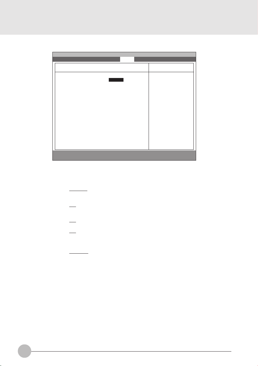
1.4.1 Power - Advanced Features Modes
Main Advanced Security Power Boot Info Exit
PhoenixBIOS Setup Utility
Advanced Features
Item Specific Help
F1 Help ↑↓ Select Item -/Space Change Value F9 Setup Defaults
ESCExit ←→ Select Menu Enter Select :Sub-Menu F10Save and Exit
Setup Item
SUS/RES Switch
Lid Closure Suspend
Lid Open Resume
Resume on LAN
Serial Mouse Activity
Suspend/Resume Switch: [Enabled]
Lid Closure Suspend: [On]
Lid Open Resume: [On]
Resume On LAN: [Off]
Serial Mouse Activity: [Disabled]
Figure 1-16 Power - Advance Features menu
Selections
Disabled
Note (Item Specific Help)
Set the SUS/RES Switch.
Enabled
Off
Set the Lid Closure Suspend.
On
Off
Set the Lid Open Resume.
On
Off
On
Turning this feature on will wake the system
up when the internal LAN device receive a
Magic Packet in Suspend Mode.
Disabled
Enabled
Turning this feature on will wake the video up
from standby mode when external serial
connector activity is detected.
Configures the
Suspend/Resume
switch.
86
Table 1-16 Power - Advanced Features menu options
Page 93

1.5 Boot Menu
:Boot Device Priority
F1 Help ↑↓ Select Item -/Space Change Value F9 Setup Defaults
ESCExit ←→ Select Menu Enter Select :Sub-Menu F10Save and Exit
Setup Item
QuickBoot Mode
Boot-time Diagnostic
Screen
Main Advanced Security Power Boot Info Exit
Quick Boot: [Enabled]
Boot-time Diagnostic Screen: [Disabled]
Preboot Execution Environment: [Disabled]
PhoenixBIOS Setup Utility
Item Specific Help
[Disabled]
All diagnostic test
will be done.
[Enabled]
Some diagnostic tests
may be skipped while
booting to speed up.
[Auto]
Diagnostic tests will
be automatically
skipped or done
according to the
order of the ACPI OS.
Figure 1-17 Boot menu
Selections
Disabled
Enabled
Auto
Disabled
Note (Item Specific Help)
Allows the system to skip certain tests while
S
booting. This will decrease the time needed
to boot the system.
Display the diagnostic screen during boot.
S
Enabled
SECTION 3
Preboot Execution
Environment
Boot Device Priority
Disabled
Enabled
Select the search order for the types of boot
devices.
Table 1-17 Boot menu options
87
Page 94

1.5. 1 Boot - Boot Device Priority Menu
Main Advanced Security Power Boot Info Exit
Floppy Disk Drive
+Hard Disk Drive
F1 Help ↑↓ Select Item -/Space Change Value F9 Setup Defaults
ESCExit ←→ Select Menu Enter Select :Sub-Menu F10Save and Exit
PhoenixBIOS Setup Utility
Boot Device Priority
Figure 1-18 Boot - Boot Device Priority menu
Setup Item
Bootable devices available are listed. The
following devices will appear depending on
the hardware configuration.
[Floppy Disk Drive]
[Hard Drive]
Table 1-18 Boot - Boot menu Device Priority options
Item Specific Help
The top device has
the highest priority.
<Enter> expands or
collapses devices
with a + or -.
<Ctrl+Enter> expands
all.
<↑> or <↓> select a
device.
<+>/<Space> or <->
move the device up or
down.
<Shift+1> enables or
disables adevice.
Note (Item Specific Help)
Use <↑> or <↓> to select a device, then press
<+> or <Space> to move it up the list, or <–>
to move it down the list. Press <Esc> to exit
this menu.
1.5. 1.1 Boot Menu at POST
The following pop up menu will appear when you hit the Esc key during POST. The device list in this
pop up menu are same as the list in the Boot Device Priority menu.
Boot Menu
1. Floppy Disk Drive
2. Hard Drive
<Enter Setup>
88
Page 95

1.6 Info Menu
Information Item
BIOS Version
Main Advanced Security Power Boot Info Exit
BIOS Version: 1.XX
BIOS Date: XX/XX/1999
BIOS Area: EC00h - FFFFh
CPU Type:
CPU Speed: XXX MHz
L1 Cache: XX KB
L2 Cache: XXX KB
Total Memory: XX MB
Onboard: XX MB SDRAM
Memory Slot: None
F1 Help ↑↓ Select Item -/Space Change Value F9 Setup Defaults
ESCExit ←→ Select Menu Enter Select :Sub-Menu F10Save and Exit
PhoenixBIOS Setup Utility
Item Specific Help
Celeron(TM) processor
Figure 1-19 Info menu
Values
Note
n.nn
SECTION 3
BIOS Date
BIOS Area
CPU Type
CPU Speed
L1 Cache
L2 Cache
Total Memory
On Board
Memory Slot
MM/DD/YYYY
xxxxh – FFFFh
Intel(R) Celeron(TM)
processor
XXX MHz
32 KB
128 KB
XX MB
64 MB SDRAM
None
16 MB SDRAM
32 MB SDRAM
64 MB SDRAM
128 MB SDRAM
Table 1-19 Info menu items
This area can not be used as UMB.
Intel(R) Celeron(TM) processor
89
Page 96

1.7 Exit menu
Main Advanced Security Power Boot Info Exit
Exit Saving Changes
Exit Discarding Changes
Load Setup Defaults
Discard Changes
Save Changes
F1 Help ↑↓ Select Item -/Space Change Value F9 Setup Defaults
ESCExit ←→ Select Menu Enter Select :Sub-Menu F10Save and Exit
Setup Item
Exit Saving Changes
Exit Discarding Changes
Load Setup Defaults
PhoenixBIOS Setup Utility
Figure 1-20 Exit menu
Note (Item Specific Help)
Exit System Setup and save your changes to
CMOS.
Exit utility without saving Setup data to CMOS.
Load default values for all SETUP items.
Item Specific Help
Exit System Setup and
save your changes to
CMOS.
Discard Changes
Save Changes
90
Load previous values from CMOS for all
SETUP items.
Save Setup Data to CMOS.
Table 1-20 Exit menu options
Page 97

1.7.1 Exit Saving Changes
1.7.4 Discard Changes
Setup Confirmation
Save configuration changes and exit now?
[Yes] [No]
1.7.2 Exit Discarding Changes
Setup Warning
Configuration has not been saved!
Save before exiting?
[Yes] [No]
1.7.3 Load Set up Defaults
Setup Confirmation
Load previous configuration now?
[Yes] [No]
Setup Confirmation
Save configuration changes now?
[Yes] [No]
1.7.5 Save Changes
Setup Confirmation
Load default configuration now?
[Yes] [No]
SECTION 3
91
Page 98

1.8 General Help
Main Advanced Security Power Boot Info Exit
Main
System Time: [ 12:34:56]
System Date: [06/02/1999]
Setup changes system behavior by modifying the BIOS
Legacy Diskette A: [1.44/1.25 MB 31/2”]
configuration. Selecting incorrect values may
cause system boot failure; load Setup Default values to
:Primary Master: [FUJITSU MHA2043AT]
recover.
:Secondary Master: [None]
:Secondary Master: [None]
<Up/Down> arrows select fields in current menu.
<Pgup/PgDn> moves to previous/next page on scrollable
System Memory: 640MB
menus.
Extended Memory: 31MB
<Home/End> moves to top/bottom item of current menu.
:Memory Cache
Within a field, <F5> or <–> selects next lower value and
Language: [English (US)]
<F6>, <+>, or <Space> selects next higher value.
F1 Help ↑↓ Select Item -/Space Change Value F9 Setup Defaults
ESCExit ←→ Select Menu Enter Select ➧Sub-Menu F10Save and Exit
PhoenixBIOS Setup Utility
General Help
[Continue]
Item Specific Help
<Tab>, <Shift-Tab or
or <Enter> selectld.
Figure 1-21 General Help
General Help
Setup changes system behavior by modifying the BIOS
configuration. Selecting incorrect values may
cause system boot failure; load Setup Default values to
recover.
<Up/Down> arrows select fields in current menu.
<PgUp/PgDn> moves to previous/next page on scrollable menus.
<Home/End> moves to top/bottom item of current menu.
:
Within a field, <F5> or <-> selects next lower value and
<F6>, <+>, or <Space> selects next higher value.
<Left/Right> arrows select menus on menu bar.
<Enter> displays more options for items marked with _.
<F9> loads factory installed Setup Default values.
<F10> saves current settings and exits Setup.
<Esc> or <Alt-X> exits Setup; in sub-menus, pressing these
keys returns to the previous menu.
<F1> or <Alt-H> displays General Help (this screen).
Table 1-21 Entire Text of General Help
92
Page 99

SECTION 3
2. POST Diagnostic Screen
PhoneixBIOS 4.0 Release 6.0
Copyright 1985-1999 Phoenix Technologies Ltd.
All Rights Reserved
Fujitsu Notebook BIOS Version 1.xx
Copyright FUJITSU LIMITED 1998-1999.
CPU = XXXX processor XXX MHz
xxM System Memory Passed
XXXK Memory Cache Passed
System BIOS Shadowed
Video BIOS Shadowed
Mouse Initialized
Fixed disk 0: xxxx
ATAPI CD-ROM: xxxx
<F12>:Boot Menu / <F2>:BIOS Setup
Figure 2-1 Typical Diagnostic Screen
Normal Messages
0640K System Memory Passed
nnnnM Extended Memory Passed
nnnnK Memory Cache Passed
System BIOS shadowed
Video BIOS shadowed
Mouse initialized
Press <F2> to enter SETUP
Entering SETUP ...
Table 2-1 Normal Messages in Diagnostic Screen
Error Messages
System Memory Failed at offset: xxxx
Failing Bits: zzzz
Extended Memory Failed at offset: xxxx
Failing Bits: zzzz zzzz
System cache error - Cache disabled
Keyboard controller error
Keyboard error
Diskette drive A error
Failure Fixed Disk n
SECTION 3
93
Page 100

Error Messages
System timer error
Real time clock error
System CMOS checksum bad - Default configuration used
Previous boot incomplete - Default configuration used
Press <F1> to resume,<F2> to Setup
Check date and time settings
Password locked: Fixed Disk n
No Save To Disk partition or file exists on Fixed Disk
- Save To Disk features is disabled.
Not enough Save To Disk partition or file exists on Fixed
Disk.
- Save To Disk feature is disabled.
Hard Disk Drive is not installed.
- Save To Disk feature is disabled.
Unknown Save To Disk error.
- Save To Disk feature is disabled.
Hard disk sector read function failed.
- Save To Disk feature is disabled.
Hard disk sector write function failed.
- Save To Disk feature is disabled.
Save To Disk par tition or file corrupted.
- Save To Disk feature is disabled.
Fixed Disk is not installed. Cannot restore from disk.
To restore from disk : turn off system, install original
fixed disk and reboot.
Press <F1> to continue to boot without save to disk
data.
Fixed Disk has been changed. Cannot restore from disk.
To restore from disk : turn off system, install original fixed
disk and reboot.
Press <F1> to continue to boot without save to disk data.
94
Table 2-2 Error Messages in Diagnostic Screen
 Loading...