

Page 1

IP-HE950
HARDWARE USER'S GUIDE
Page 2
IP-HE950 Hardware User's Guide
This document includes technology controlled under the Foreign Exchange and Foreign Trade
authorization from the appropriate governmental authorities in accordance with the above law.
The IP-HE950 is designed and manufactured for use in standard applications such as office
sales representative before embarking on such specialized use.
USING IP-HE950 SAFELY
Handling of This Document
This document contains important information regarding the safe use of the IP-HE950. Read it
thoroughly before operating this unit. Make sure that users of this equipment read and
understand thoroughly all safety precautions contained in the document. Keep the document in
a safe and convenient location for quick reference.
Fujitsu makes every effort to prevent users and bystanders from being injured and to prevent
property damage. Be sure to use this unit in accordance with instructions in the document.
Warning on Electromagnetic Interference
The following notice is for USA users only.
The IP-HE950 has been tested and found to comply with the limits for a Class A digital unit,
pursuant to Part 15 of the FCC rules. These limits are designed to provide reasonable
protection against harmful interference when the equipment is operated in a commercial
environment. This equipment generates, uses, and can radiate radio frequency energy and, if
not installed and used in accordance with the instruction document, may cause harmful
interference to radio communications. Operation of this equipment in a residential area is likely
to cause harmful interference in which case the user will be required to correct the interference
at one's own expense.
The following notice is for Canada users only.
This Class A digital apparatus meets all requirements of the Canadian Interference-Causing
Equipment Regulations.
The following notice is for EU (European Union) users only.
This is a Class A product of Electromagnetic Interference (EMI) standard. In a domestic
environment this product may cause radio interference in which case the user may be required
to make adequate measures.
Control Law. The document or a portion thereof must not be exported (or re-exported) without
work, personal units, and household appliances. The product is not intended for special uses
(such as nuclear-reactor control in atomic energy facilities, aeronautics and space systems, air
traffic control, operation control in mass transit systems, medical units for life support, and
missile firing controls in weapons facilities) where particularly high reliability requirements exist,
where the pertinent levels of safety are not guaranteed, or where a failure or operational error
could threaten a life or cause physical injury (hereafter referred to as "mission-critical" use).
Customers considering use of this product for mission-critical applications must have
safety-assurance measures in place beforehand. Moreover, they are requested to consult our
Copying of and disassembly, decompilation, and other forms of reverse-engineering of any
programs included with this unit are prohibited.
Microsoft, Windows, and Internet Explorer are trademarks or registered trademarks of
Microsoft Corporation in the United States and/or other countries.
Copyright 2017 FUJITSU LIMITED
i
Page 3

IP-HE950 Hardware User's Guide
Macintosh, Mac OS, and Safari are trademarks or registered trademarks of Apple Inc. in the
United States.
Google Chrome and Android are registered trademarks of Google Inc.
No part of this document shall be reproduced in any way or form without the permission of
Fujitsu Limited.
Copyright 2017 FUJITSU LIMITED
ii
Page 4

IP-HE950 Hardware User's Guide
PREFACE
Thank you for purchasing the IP-HE950 (H265/HEVC CODEC).
The IP-HE950 is a video transmission unit with H.265/HEVC encoding technology, which performs at
a high compression rate.
This document explains how to use the hardware of the IP-HE950.
This document is intended for system designers and administrators who use the IP-HE950. Readers
are assumed to have a basic understanding of networks and video distribution.
Edition 2
July 2017
Product operating environment
The IP-HE950 is intended for use with indoor systems.
Note
The contents of this document are subject to change without notice.
Copyright 2017 FUJITSU LIMITED
iii
Page 5

IP-HE950 Hardware User's Guide
ORGANIZATION AND CONTENTS OF
THIS DOCUMENT
This document consists of five chapters, an appendix, and a glossary.
Read Chapters 1 and 2 first for information on installing and connecting the IP-HE950. Then, read
Chapter 3 for operating instructions. Chapter 4 and subsequent chapters can be read as required.
Chapter 1 Preparations
This chapter describes the checks that are required before the start of IP-HE950 operation.
Chapter 2 Installation and Connection
This chapter describes IP-HE950 installation conditions and how to connect it to its peripherals.
Chapter 3 Operating Instructions
This chapter describes how to turn on/off, set up, and operate this unit.
Chapter 4 Connection Cable Specifications
This chapter describes the scope of IP-HE950 installation work and contains cable connection
system diagrams and cable and connector details.
Chapter 5 Troubleshooting
This chapter describes the actions to take if, for example, this unit does not operate normally or if an
alarm LED goes on.
Appendix
The appendix contains views of this unit and lists its main specifications. Precautions and other such
notes on installation work and on-site tune-up are also covered in this section.
Glossary
The glossary describes the technical terms that readers of this document need to know.
Copyright 2017 FUJITSU LIMITED
iv
Page 6

IP-HE950 Hardware User's Guide
WARNING
or loss of life if procedures are not followed correctly.
CAUTION
property if procedures are not followed correctly.
is the symbol shown to tell the reader about an act that must not
symbol.
are shown centered under and to the side of the symbol.
Instruction
Prohibited
WARNING INDICATIONS
This document uses warning indications to warn of conditions in order to prevent serious
injury and property damage. Warning indications consist of warning markings of specific
levels and warning messages. The warning markings are shown below along with their
definitions.
WARNING indicates a situation that could lead to serious injury
CAUTION indicates a situation that could lead to minor or
moderate injury and/or damage to the IP-HE950 itself or other
In addition, the following symbols are used together with the above-shown indicators to
indicate details of the pertinent risk and/or damage.
be done (prohibited act). Specific warning details ("Prohibited" on
the left here) are shown centered under and to the side of the
is the symbol shown to tell the reader to be sure to follow
instructions. Specific warning details ("Instruction" on the left here)
Copyright 2017 FUJITSU LIMITED
v
Page 7

IP-HE950 Hardware User's Guide
WARNING
Warning indications within text
Warning markings are followed by warning messages. Every warning marking is centered on
a line. Left and right indents are set for warning messages to differentiate them from ordinary
text. Furthermore, the lines immediately before and after warning indications are left blank.
(Example)
Possibility of electric shock, fire, and damage to this unit
Always observe the precautions given below.
There may be a hazardous situation that could lead to electric shock, fire,
and damage to this unit.
- Always connect the power cord to a power receptacle for a standard
two-prong plug with ground.
- Connect this unit to a power receptacle with a capacity of 1 A or more.
When using a power extension cable, be sure that the total power
consumption of all equipment connected to the cable does not exceed
the rated capacity of the cable. If a power receptacle with a low
capacity or capacity below the rated value is used, the power
receptacle, extension cable, or power distribution wiring may overheat
and start a fire.
Important warning indications are summarized below in "Safety Precautions."
Copyright 2017 FUJITSU LIMITED
vi
Page 8
IP-HE950 Hardware User's Guide
Work time
Warning
mes
hazardous
if procedures are not followed correctly.
Prohibited
Prohibited
Prohibited
Instruction
Instruction
Instruction
SAFETY PRECAUTIONS
List of important warnings
The following table shows a list of important warnings.
This indicates a situation that could lead to serious injury or loss of life
Normal use
WARNING
Possibility of electric shock and fire
Ensure that drink containers and metal objects are not placed on or near this
unit.
The presence of foreign matter such as water inside this unit creates a
hazardous situation that could lead to electric shock and fire.
Possibility of electric shock and fire
Ensure that no liquid is splashed on this unit, making it wet.
The presence of foreign matter such as water inside this unit creates a
hazardous situation that could lead to electric shock and fire.
Possibility of electric shock and fire
Ensure that the power cord does not become damaged, and avoid tampering
with it.
If the power cord has a heavy object placed on it, is pulled or bent, or beco
entangled, it could be damaged as a result. The power cord could also be
damaged if subjected to heat. Damage to the power cord creates a
situation that could lead to electric shock and fire.
Possibility of electric shock and fire
If excessive heat, smoke, an abnormal odor, or an unusual noise is coming
from this unit, immediately set the power switch to the OFF position and
remove the power cord plug from the power receptacle. Then, contact a
Fujitsu Service Center.
There may be a hazardous situation that could lead to electric shock and fire.
Possibility of electric shock and fire
If foreign matter (e.g., water, bits of metal, fluid) gets inside this unit,
immediately set the power switch to the OFF position and remove the power
cord plug from the power receptacle. Then, contact a Fujitsu Service Center.
There may be a hazardous situation that could lead to electric shock and fire.
Possibility of electric shock and fire
If this unit has been dropped or otherwise damaged, immediately set the
power switch to the OFF position and remove the power cord plug from the
power receptacle. Then, contact a Fujitsu Service Center.
There may be a hazardous situation that could lead to electric shock and fire.
Copyright 2017 FUJITSU LIMITED
vii
Page 9

IP-HE950 Hardware User's Guide
Work time
Warning
inlet connector.
Instruction
Prohibited
Installation Possibility of electric shock and fire
Do not install this unit in the following places because electric shock and fire
may result from operation there:
- Extremely dusty or dirty location
- Wet and humid location
- Hot location, such as a place where this unit is exposed to direct
sunlight or is near heating equipment
- Near products (e.g., speakers) that generate a strong magnetic field
- Location where the temperature is too hot or cold
- In an environment with sharp temperature fluctuations
- Area with poor ventilation
- Near a fire
Possibility of electric shock, fire, and damage to this unit
Always observe the precautions given below.
There may be a hazardous situation that could lead to electric shock, fire, and
damage to this unit.
- Always connect the power cord plug to a power receptacle for a standard
two-prong plug with ground.
- The AC power cord supplied with the unit supports voltages up to the rated
voltage of 125 V. To use the IP-HE950 above the rated voltage of 125 V,
refer to "4.2 Cable and Connector Details," and select another power cord.
- Connect the IP-HE950 to a power receptacle with a capacity of 1 A or more.
When using a power extension cable, be sure that the total current
consumption of all equipment connected to the cable does not exceed the
rated capacity of the cable. If a power receptacle with a low capacity or
capacity below the rated value is used, the power receptacle, extension
cable, or power wiring may overheat and start a fire.
- This unit is shut off by pulling out the power cord from the unit’s power inlet
connector. Please install this unit where you can easily access the power
Copyright 2017 FUJITSU LIMITED
viii
Page 10
IP-HE950 Hardware User's Guide
Work time
Precaution
Installation and
and attention to your surroundings.
from
a button/switch or opening.
a
Never forcibly remove the module because that may cause damage.
Instruction
Prohibited
Instruction
Prohibited
Instruction
Prohibited
This indicates a situation that could lead to minor or moderate injury
CAUTION
and/or damage to this unit itself or other property if procedures are not
followed correctly.
relocation
Do not install this unit in a place where it is exposed to shock and strong
vibrations, on an incline, or at an unstable location. Otherwise, there may be
a hazardous situation that could lead to serious injury and damage to this
unit.
Possibility of serious injury and damage to this unit
When relocating this unit, observe the precautions given below to protect
against injury and damage to the unit.
- Set the power switch to the OFF position, and disconnect all connected
cables. Take care to avoid getting your feet entangled in the cables.
- To prevent serious personal injury when moving the unit, pay special care
Cleaning Possibility of fire, serious injury, and damage to this unit
When cleaning this unit, observe the precautions given below to protect
against fire, serious injury, and damage to the unit.
- When cleaning the unit, do not use cleaning spray that contains
combustible material. Furthermore, do not use such spray around the unit.
- When cleaning the unit, wipe it with a cloth with the water (or neutral
detergent diluted in water) squeezed out.
- When wiping, be careful to prevent water from entering the IP-HE950
Possibility of serious injury and damage to this unit
Maintenance
Possibility of serious injury and damage to this unit
When performing maintenance on this unit, observe the precautions given
below to protect against serious injury and damage to the unit.
- Be sure to turn off the power and then unplug the power cord from the
power receptacle before installing or removing an SFP module, which is
hardware option. Furthermore, when connecting this unit with a
conversion cable, pay special care and attention to not damage the
conversion cable.
- The SFP module has a lock mechanism. Firmly insert the module until it
locks. When removing the module, hold down the unlock mechanism.
ix
Copyright 2017 FUJITSU LIMITED
Page 11
IP-HE950 Hardware User's Guide
LISTED
R
C US
1K91
I T E
E136004
Manufacture
Fujitsu Limited
Address: 1-1, Kamikodanaka 4-Chome, Nakahara-Ku, Kawasaki 211-8588, Japan
Authorised representative
Fujitsu Services Limited
Address: 22 Baker Street, London, W1U 3BW, United Kingdom
CAN ICES-3 (A) / NMB-3 (A)
MODEL
PART NO.
IP-HE950E
TA24372-B10X
This device complies with Part 15 of the FCC Rules.
operation is subject to the foll owing two conditions:
(1) This device may not cause harmful interference. and
(2) this device must accept any interference received,
including interference that may cause undesi red operation.
MADE IN JAPAN
0.93A-0.53A
1φ
100V-240V~
50/60Hz
2.5kg
0.093kVA-0.126kVA
T
認証番号
D17-0005001
FUJITSU LIMITED
01A
17-03
00001
IP-HE950E
TA24372-B10X
00001
01A 17-03
F
LISTED
R
C US
1K91
I T E
E136004
Manufacture
Fujitsu Limited
Address: 1-1, Kamikodanaka 4-Chome, Nakahara-Ku, Kawasaki 211-8588, Japan
Authorised representati ve
Fujitsu Services Limited
Address: 22 Baker Street, London, W1U 3BW, United Kingdom
CAN ICES-3 (A) / N MB-3 (A)
MODEL
PART NO.
IP-HE950E
TA24372-B10X
This device complies with Part 15 of the FCC Rules.
operation is subj ect to the following two conditi ons:
(1) This device may not cause harmful interference. and
(2) this device must accept any interference received,
including i nterference that may cause undesired operation.
MADE IN JAPAN
0.93A-0.53A
1φ
100V-240V~
50/60Hz
2.5kg
0.093kVA-0.126kVA
T
認証番号
D17-0005001
FUJITSU LIMITED
01A
17-03
00001
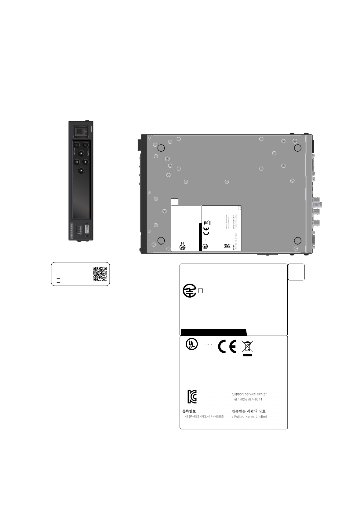
The labels shown below are affixed to this unit.
Never remove the labels. If one becomes dirty and the message becomes difficult to read,
contact a Fujitsu Service Center.
The following labels are intended for users of this unit.
- Example of labels shown on the IP-HE950E
LABEL
Figure A Labels shown
x
Copyright 2017 FUJITSU LIMITED
Page 12

IP-HE950 Hardware User's Guide
WARNING
CAUTION
PRODUCT HANDLING PRECAUTIONS
Maintenance
Do not try to repair this equipment yourself. Contact a Fujitsu Service
Center.
Read this document thoroughly before attempting to operate this equipment.
If you have any questions, contact a Fujitsu Service Center.
If a problem occurs, contact a Fujitsu Service Center.
The Fujitsu Service Center will ask you to describe the problem, the lamp display status of
alarm LEDs, and other details. Check the system for this information.
Connectable equipment
Only equipment that conforms to the interface specifications of this unit (refer to "A.2.3
Interface specifications") can be connected. If incompatible equipment is connected, the result
may be unexpected personal injury and property damage.
Disposal
To dispose of this unit, contact a Fujitsu Service Center, or request a specialist to take care of
its disposal.
Modification and rebuild
Do not use this unit if it has been modified or rebuilt, such as by an overhaul with
refurbished/used parts. Otherwise, the result may be unexpected personal injury and property
damage.
Copyright 2017 FUJITSU LIMITED
xi
Page 13

IP-HE950 Hardware User's Guide
CONTENTS
USING IP-HE950 SAFELY ........................................................................................................... i
PREFACE ................................................................................................................................... iii
ORGANIZATION AND CONTENTS OF THIS DOCUMENT ..................................................... iv
WARNING INDICATIONS ........................................................................................................... v
SAFETY PRECAUTIONS.......................................................................................................... vii
LABEL .......................................................................................................................................... x
PRODUCT HANDLING PRECAUTIONS ................................................................................... xi
Chapter 1 Preparations ·················································································· 1
1.1 Main Features ................................................................................................................. 2
1.2 Components ................................................................................................................... 4
1.3 Typical Applications ........................................................................................................ 5
1.4 Parts Names ................................................................................................................... 6
Chapter 2 Installation and Connection····························································· 9
2.1 Installation Conditions ................................................................................................... 11
2.1.1 Environmental conditions ....................................................................................... 11
2.1.2 Installation environment ......................................................................................... 11
2.1.3 Intake and exhaust ................................................................................................ 21
2.1.4 Installation space ................................................................................................... 21
2.2 Power Supply Connections .......................................................................................... 22
2.2.1 Connection to ground ............................................................................................ 22
2.2.2 Connection to a power source .............................................................................. 23
2.3 Connection to SDI Equipment ...................................................................................... 26
2.3.1 Connection to SDI output equipment .................................................................... 26
2.3.2 Connection to SDI input equipment ...................................................................... 27
2.4 Connection to External Sync Signals (REF) ................................................................ 28
2.5 Connection to DVB-ASI Equipment ............................................................................. 29
2.5.1 Connection to DVB-ASI input equipment .............................................................. 29
2.5.2 Connection to DVB-ASI output equipment ........................................................... 30
2.6 Connection to LAN Equipment ..................................................................................... 31
2.7 Connection to Quad Link 3G-SDI Equipment .............................................................. 33
Chapter 3 Operation Instructions ·································································· 35
3.1 Turning On/Off the IP-HE950 ....................................................................................... 36
3.1.1 Turning on the IP-HE950....................................................................................... 36
3.1.2 Turning off the IP-HE950 ....................................................................................... 36
3.2 Unit Settings and Operation (WEB) ............................................................................. 37
3.3 Unit Settings and Operation (VFD) .............................................................................. 38
3.4 Special Use of the CANCEL Key ................................................................................. 39
Chapter 4 Cable Specifications ····································································· 40
4.1 Installation Preparations ............................................................................................... 41
4.2 Cable and Connector Details ....................................................................................... 43
Chapter 5 Troubleshooting··········································································· 47
5.1 Help Information ........................................................................................................... 48
5.2 Alarm LED Goes On ..................................................................................................... 55
5.3 Maintenance ................................................................................................................. 56
5.3.1 Maintenance area.................................................................................................. 56
5.3.2 Unit (maintenance part) replacement .................................................................... 57
5.3.3 SFP module (maintenance part) replacement ...................................................... 57
5.3.4 Cable and SFP module removal procedures ........................................................ 57
Appendix ··································································································· 58
A.1 Appearance .................................................................................................................. 59
A.1.1 IP-HE950E ............................................................................................................ 59
Copyright 2017 FUJITSU LIMITED
I
Page 14

IP-HE950 Hardware User's Guide
A.1.2 IP-HE950D ............................................................................................................ 60
A.2 Main Specifications ....................................................................................................... 61
A.2.1 External specifications .......................................................................................... 61
A.2.2 Environmental specifications................................................................................. 61
A.2.3 Interface specifications .......................................................................................... 62
A.3 Installation Work ........................................................................................................... 69
A.3.1 Installation work scope .......................................................................................... 69
A.3.2 Unpacking and unit check ..................................................................................... 69
A.3.3 Installation conditions ............................................................................................ 69
A.3.4 Connecting external cables ................................................................................... 69
A.4 On-Site Tune-Up Work ................................................................................................. 70
Glossary ···································································································· 73
Glossary .................................................................................................................................... 74
II
Copyright 2017 FUJITSU LIMITED
Page 15

IP-HE950 Hardware User's Guide Chapter 1 Preparations
Chapter 1 Preparations
Chapter 1
Preparations
This chapter describes an overview of IP-HE950 operation.
1.1 Main Features ············································································· 2
1.2 Components ··············································································· 4
1.3 Typical Applications ······································································ 5
1.4 Parts Names ··············································································· 6
1
Copyright 2017 FUJITSU LIMITED
Page 16
IP-HE950 Hardware User's Guide Chapter 1 Preparations
1 x [BNC]: 12G/3G/HD/SD-SDI
1 x [BNC]: 12G/3G/HD/SD-SDI
2 x [SFP]: Quad 3G-SDI output
Display part
VFD (22 characters x 4 lines)
Operation part
Operation keys (, ENTER, CANCEL)
2 x [RJ45]:
BASE-T (control shared)
2 x [RJ45]:
E-T (control shared)
DVB-ASI
2 x [BNC]: DVB-ASI output
1 x [BNC]: DVB-ASI input
AUX data
1 x [D-sub9 female]: RS-232C/RS-422
Installation conditions
Indoor: Desktop installation or rack mounted
External dimensions
210 (W) x 300 (D) x 43 (H) mm
Cooling method
Forced air cooling
Power
100 to 240 VAC
Weight
Max. 2.5 kg
Power consumption
126 VA or less
122 VA or less
Temperature and
humidity conditions
-10 to 55°C (except for startup under 0°C) / 20% to 90% RH (no
condensation)
1.1 Main Features
1.1
The IP-HE950 is a video transmission unit with H.265/HEVC encoding technology, which
performs at a high compression rate.
The IP-HE950 supports H.265/HEVC 4:2:2 10-bit and 4K/2160p, and provides high-quality
video encoding. It also supports the H.264 encoding format, ensuring connectivity with existing
H.264 units.
The IP-HE950 is equipped with the SFP module interface as well as the SDI input/output
interface. Through a combination of option licenses, the unit can be scaled to diverse interface
configurations matching operation scenarios.
The encoder can store compressed video and audio in files to fetch and transmit them to
decoders at any time. In addition, the decoders that received the files can play them offline.
In addition to Fujitsu's high-quality video compression technology, the IP-HE950 inherits
powerful fault tolerance technology for IP networks from H.264 units.
The IP-HE950 provides high operability. You can operate the unit from the Web GUI, the front
panel, and SN MP.
In order for this unit to operate, you will need to purchase and install a software license. For
details, refer to the IP-HE950 Software User's Guide.
Tab le 1-1 Specifications
Product name
Function
IP-HE950E IP-HE950D
Video and audio I/F
Network
input
1 x [D-sub9 female]: AES-EBU
2 stereo input, Analog
(Balanced) 1 stereo input
2 x [SFP]: Quad 3G-SDI input
10BASE-T/100BASE-TX/1000
output
1 x [D-sub9 female]: AES-EBU 2
stereo output, Analog (Balanced) 1
stereo output
1 x [BNC]: Reference input
1 x [BNC]: Reference output
10BASE-T/100BASE-TX/1000BAS
2
Copyright 2017 FUJITSU LIMITED
Page 17

IP-HE950 Hardware User's Guide Chapter 1 Preparations
Table 1-2 Hardware options
Hardware option Description
Quad 3G-SDI input option
Quad 3G-SDI output option
Quad 3G-SDI conversion cable
option
Supports 3G-SDI x 4 inputs.
(For IP-HE950E: SFP module x 2)
Supports 3G-SDI x 4 outputs.
(For IP-HE950D: SFP module x 2)
Conversion cable from HD-BNC to BNC
(For Quad 3G-SDI input/output option)
Rack Mounting Kit Type A1 19" rack mounting kit (for 1 unit)
Rack Mounting Kit Type C2 19" rack mounting kit (for 2 units)
For software options, refer to the IP-HE950 Software User's Guide.
3
Copyright 2017 FUJITSU LIMITED
Page 18
IP-HE950 Hardware User's Guide Chapter 1 Preparations
1.2 Components
1.2
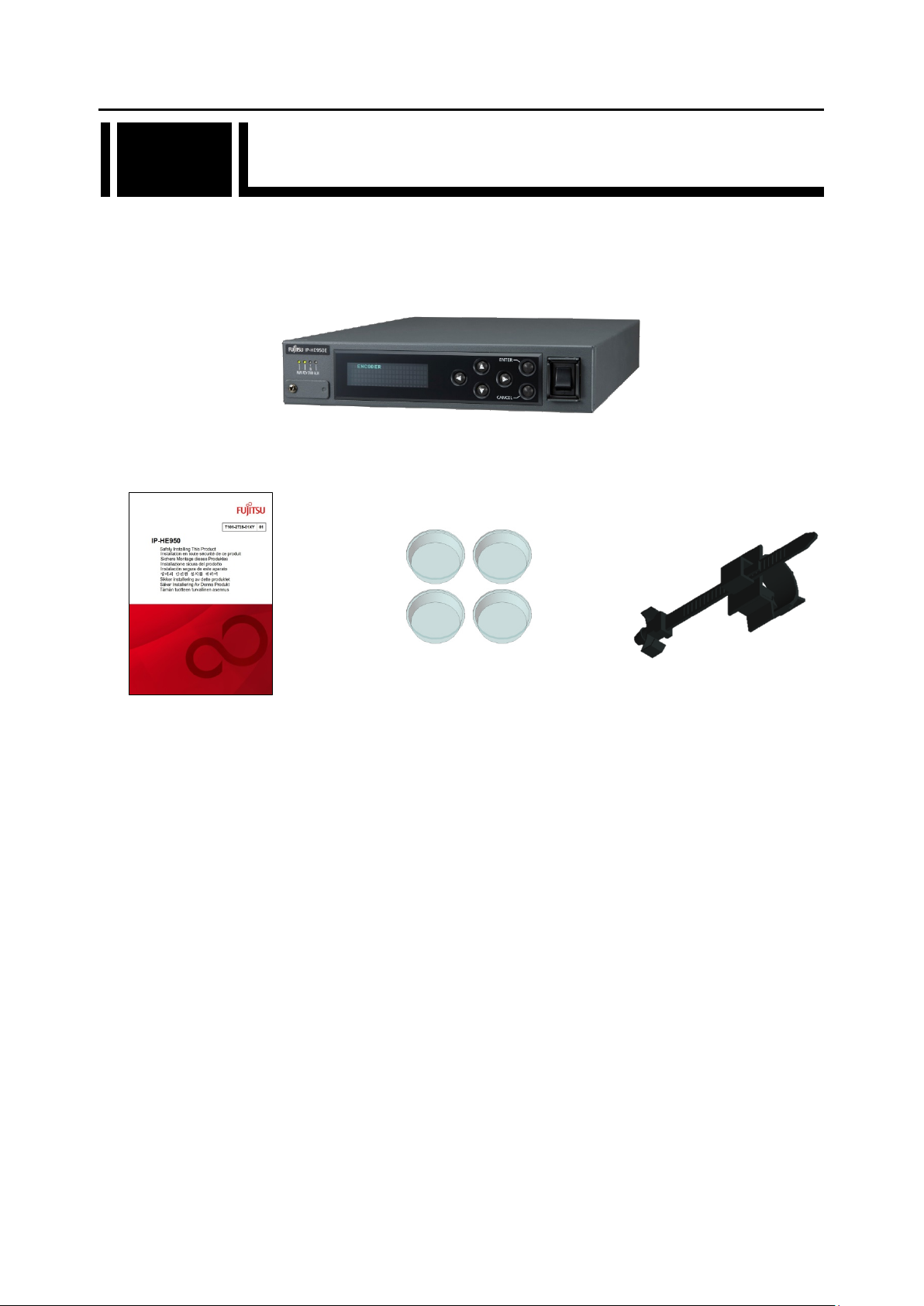
The IP-HE950 product package consists of the main unit, a safety manual, rubber feet, and a
power cord holder (AC cord clamp). In addition, you can procure each of them separately as
required.
- IP-HE950 x 1 (Cables for various connections are procured separately.)
- Safety manual x 1 - Rubber foot x 4 - Power cord holder x 1
(AC cord clamp)
Figure 1-1 Component list
4
Copyright 2017 FUJITSU LIMITED
Page 19
IP-HE950 Hardware User's Guide Chapter 1 Preparations
IP-HE950E
Live
SDI
SDI
Monitor
Camera
IP-HE950D
IP-HE950E
Live distribution
SDI
SDI
Monitor
Camera
IP-HE950D
DVB-ASI
DVB-ASI
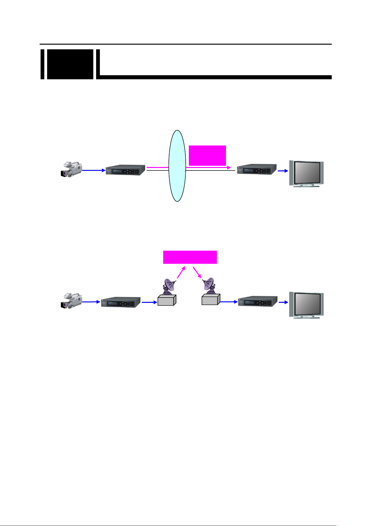
1.3 Typical Applications
1.3
This section shows IP-HE950 application examples (examples of system configurations
using the IP-HE950).
The basic configuration is for video transfer over point-to-point connections.
Here, a camera is connected to the encoder, and video is transferred to the decoder via the
Internet and output to the monitor.
Figure 1-2 Sample System configuration: Broadcast
Contents transmission and live coverage
Internet
distribution
By using the DVB-ASI interface provided as a standard function, the IP-HE950 can transmit
video via SNG (Satellite News Gathering) and FPUs (Field Pickup Units).
Figure 1-3 Sample System configuration: SNG
Copyright 2017 FUJITSU LIMITED
5
Page 20
IP-HE950 Hardware User's Guide Chapter 1 Preparations
No.
Name
Function
Port used by a customer engineer. Normally, it is not used. The
cover is fixed in place with a screw.
USB port supported in the future. This is disabled now. The
cover is fixed in place with a screw. Never remove the cover.
Used to display the unit status and make various settings. 22
characters x 4 lines
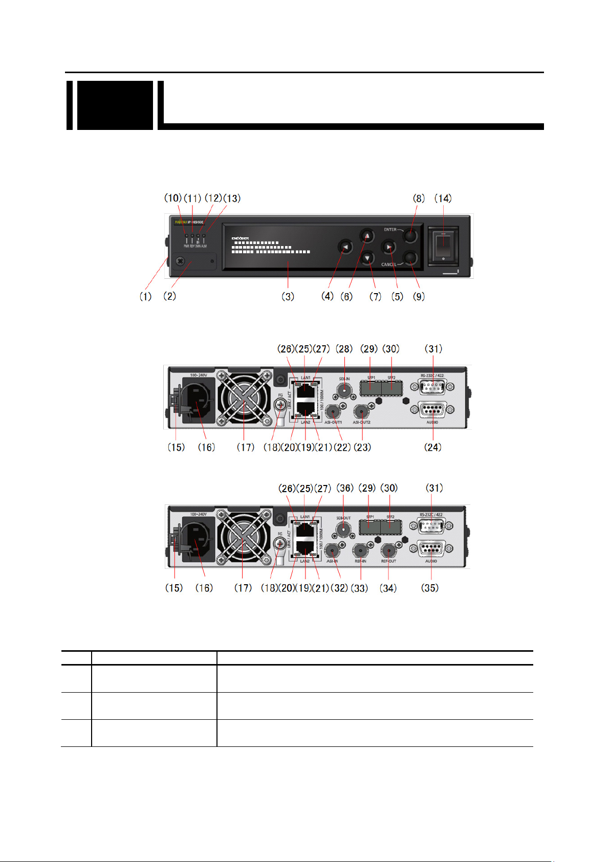
1.4 Parts Names
1.4
This section describes the name and function of each part of the IP-HE950.
The following figures show the layouts of parts on the outside of this unit, and the table
underneath lists the names and functions of individual parts. The numbers in the figures
correspond to the numbers in the table.
Figure 1-4 Front view (common to the IP-HE950E and IP-HE950D)
Figure 1-5 Rear view (IP-HE950E)
Figure 1-6 Rear view (IP-HE950D)
Table 1-3 Parts names
Maintenance port
(1)
USB port
(2)
Front panel
(3)
Copyright 2017 FUJITSU LIMITED
6
Page 21

IP-HE950 Hardware User's Guide Chapter 1 Preparations
(4)
(5)
(6)
(7)
ENTER key
(ENTER)
Used to finalize the displayed data on the Front panel.
For instructions, refer to the IP-HE950 Software User's Guide.
CANCEL key
(CANCEL)
Used to cancel the displayed data on the Front panel.
For instructions, refer to the IP-HE950 Software User's Guide.
Power LED
(PWR)
Turns on or blinks when input is abnormal (input down/input
For details, refer to "Table 5-3 LED indications" in Section 5.2.
Powers on/off this unit with 100-240 VAC. For instructions, refer
to "3.1 Turning On/Off the IP-HE950."
FG terminal
Status LED
(LINK/ACT)
LED that shows the status of LAN port 2. For details, refer to
"Table 5-3 LED indications" in Section 5.2.
details, refer to
DVB-ASI output
output.
For cable connection information, refer to "4.2 Cable and
Direction keys
()
(8)
(9)
(10)
Status LED
(11)
(RDY)
Video input status LED
(12)
(INDWN)
Alarm LED
(13)
(ALM)
(14) Power switch
AC cord clamp
(15)
Used to operate the Front panel.
For instructions, refer to the IP-HE950 Software User's Guide.
Goes on when this unit is powered on.
LED that shows the operating status of the IP-HE950. The LED
light color is green when operation is normal.
For details, refer to "Table 5-3 LED indications" in Section 5.2.
error).
Turns on or blinks when operation is abnormal.
For details, refer to "Table 5-3 LED indications" in Section 5.2.
AC cord clamp for fixing the power cord in place. For instructions,
refer to "2.2.2 Connection to a power source."
(16) Power inlet connector
(17) Fan
(18)
(FG)
ETHERNET port 2 for
LAN connection
(19)
(LAN2)
(20)
(21)
(22)
(23)
Speed LED
(100/1000M)
(ASI-OUT1)
DVB-ASI output
(ASI-OUT2)
Can be connected to a 100-240 VAC commercial power supply
by a power cord with a standard two-prong plug with ground.
For instructions, refer to "2.2.2 Connection to a power source."
For cable connection information, refer to "4.2 Cable and
Connector Details."
Maintenance-free fan for cooling the inside of the unit.
Used to connect FG to this unit when required.
For instructions, refer to "2.2.1 Connection to ground."
10BASE-T/100BASE-TX/1000BASE-T communication port.
For instructions, refer to "2.6 Connection to LAN Equipment." For
cable connection information, refer to "4.2 Cable and Connector
Details."
LED that shows the speed of LAN port 2. For
"Table 5-3 LED indications" in Section 5.2.
DVB-ASI output connectors. Output is 75 Ω unbalanced
For instructions, refer to "2.5 Connection to DVB-ASI Equipment."
Connector Details."
External audio input
(24)
(AUDIO)
External audio input connector supported in the future. This is
disabled now.
7
Copyright 2017 FUJITSU LIMITED
Page 22

IP-HE950 Hardware User's Guide Chapter 1 Preparations
Status LED
(LINK/ACT)
LED that shows the status of LAN port 1. For details, refer to
"Table 5-3 LED indications" in Section 5.2.
Speed LED
(100/1000M)
LED that shows the speed of LAN port 1. For details, refer to
"Table 5-3 LED indications" in Section 5.2.
Connector for SD-SDI, HD-SDI, 3G-SDI, and 12G-SDI signal
For cable connection information, refer to "4.2 Cable and
Connector Details."
SFP input
(SFP1)
Connector for mounting a SFP module. Designated hardware
2.7 Connection to
For cable connection information,
refer to "4.2 Cable and Connector Details."
SFP input
(SFP2)
RS-232C or RS-422 external control communication port.
refer to "4.2 Cable and Connector Details." This is disabled now.
DVB-ASI input connector. Input is 75 Ω unbalanced input. For
Details."
External sync input connector. Input is 75 Ω unbalanced inputs.
Connector Details."
External sync output connector. Output is 75 Ω unbalanced
Cable and Connector Details."
External audio output
(AUDIO)
External audio connector supported in the future. This is disabled
now.
Connector for SD-SDI, HD-SDI, 3G-SDI, and 12G-SDI signal
Connector Details."
ETHERNET port 1 for
LAN connection
(25)
(LAN1)
(26)
(27)
SDI input
(28)
(SDI-IN)
(29)
(30)
External control
(31)
(RS-232C/422)
DVB-ASI input
(32)
(ASI-IN)
10BASE-T/100BASE-TX/1000BASE-T communication port.
For instructions, refer to "2.7 Connection to LAN Equipment." For
cable connection information, refer to "4.2 Cable and Connector
Details."
input.
options are available. For instructions, refer to "
Quad Link 3G-SDI Equipment."
For instructions, refer to "2.5 Connection to RS-232C/RS-422
Device" in a related manual. For cable connection information,
instructions, refer to "2.5 Connection to DVB-ASI Equipment." For
cable connection information, refer to "4.2 Cable and Connector
External sync input
(33)
(REF-IN)
External sync output
(34)
(REF-OUT)
(35)
SDI output
(36)
(SDI-OUT)
For instructions, refer to "2.4 Connection to External Sync Signals
(REF)." For cable connection information, refer to "4.2 Cable and
output. For instructions, refer to "2.4 Connection to External Sync
Signals (REF)." For cable connection information, refer to "4.2
output. For cable connection information, refer to "4.2 Cable and
8
Copyright 2017 FUJITSU LIMITED
Page 23

IP-HE950 Hardware User's Guide Chapter 2 Installation and Connection
Chapter 2
Chapter 2 Installation and Connection
Installation and Connection
This chapter describes IP-HE950 installation conditions and how to
connect it to its peripherals.
2.1 Installation Conditions ································································· 11
2.2 Power Supply Connections ·························································· 22
2.3 Connection to SDI Equipment ······················································· 26
2.4 Connection to External Sync Signals (REF) ····································· 28
2.5 Connection to DVB-ASI Equipment ··············································· 29
2.6 Connection to LAN Equipment ······················································ 31
2.7 Connection to Quad Link 3G-SDI Equipment ··································· 33
9
Copyright 2017 FUJITSU LIMITED
Page 24

IP-HE950 Hardware User's Guide Chapter 2 Installation and Connection
Possibility of serious injury
- The power cord and other cables connected to the IP-HE950 could
become tangled with someone walking close to them, possibly leading
to serious injury and property damage. Clamp the cables to the rack or
floor.
Caution
10
Copyright 2017 FUJITSU LIMITED
Page 25
IP-HE950 Hardware User's Guide Chapter 2 Installation and Connection
2.1 Installation Conditions
2.1
This section describes the installation environment, intake and exhaust, and unit space.
2.1.1 Environmental conditions
Use this unit in an environment where the intake temperature and ambient temperature do not
exceed 55°C.
When the above conditions are observed, you can stack and operate the IP-HE950.
Conversely, in an environment where the above conditions are not observed, any use of the
unit is outside the guaranteed operating range, possibly leading to a failure and remarkably
shortened product life.
Use this unit in an environment where the concentration of airborne dust is no more than 0.15
3
. (If it is 0.15 mg/m3 or higher, use a dust-proof rack.) In addition, clean around the unit
mg/m
to prevent significant amounts of dust from adhering to it. Otherwise, the dust may cause unit
errors and failures.
Use this unit in an environment where the corrosive gas concentration is under the allowable
level stipulated in IEC 60721-3-3 Class 3C1.
2.1.2 Installation environment
1. Mounting in a 19" rack
Use the 19" rack mount kit to mount this unit in an EIA standard 19" rack.
We have two types of mount kit: one accommodates a single unit per 1U space, and the
other accommodates two units per 1U space.
(The 19" rack mount kit is an optional product.)
If you want to mount the unit in a different form than described in this document, consult a
Fujitsu sales representative or your system designer.
Be sure to use those mounting brackets and screws enclosed in the rack
mount option to attach to the IP-HE950. In rack mounting, secure the unit
tightly to the rack by using the screws that come with the rack mount option
or the rack.
If the screws loosen or are not tightened enough, they may lead to a serious
accident.
CAUTION
Copyright 2017 FUJITSU LIMITED
11
Page 26
IP-HE950 Hardware User's Guide Chapter 2 Installation and Connection
C
B
A
D
A
B
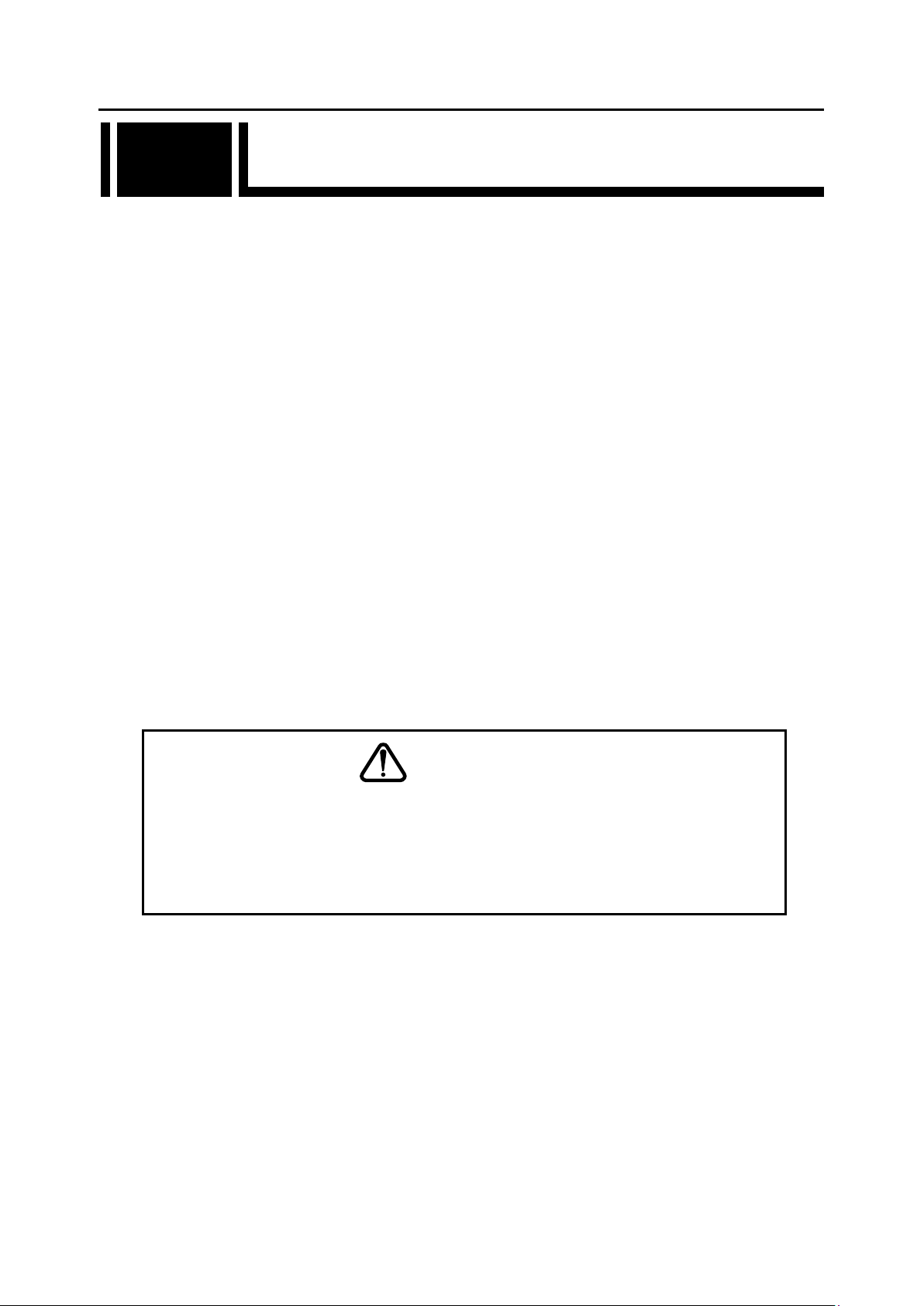
- Mounting two IP-HE950 per 1U (Type: C2)
(1) Confirm the components of the rack mount kit.
(2) Confirm that all cables are disconnected.
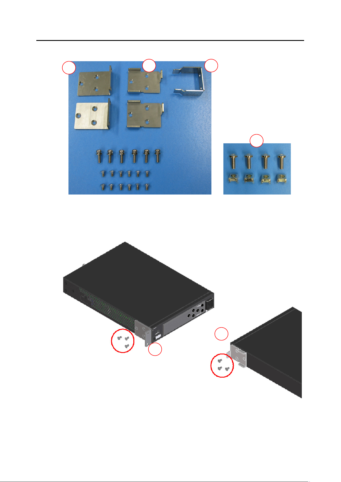
(3) Attach rack mounting brackets A and B to the side of the first IP-HE950. Tighten screws
(M4) at the six places shown in the following figure.
Copyright 2017 FUJITSU LIMITED
12
Page 27
IP-HE950 Hardware User's Guide Chapter 2 Installation and Connection
A
B
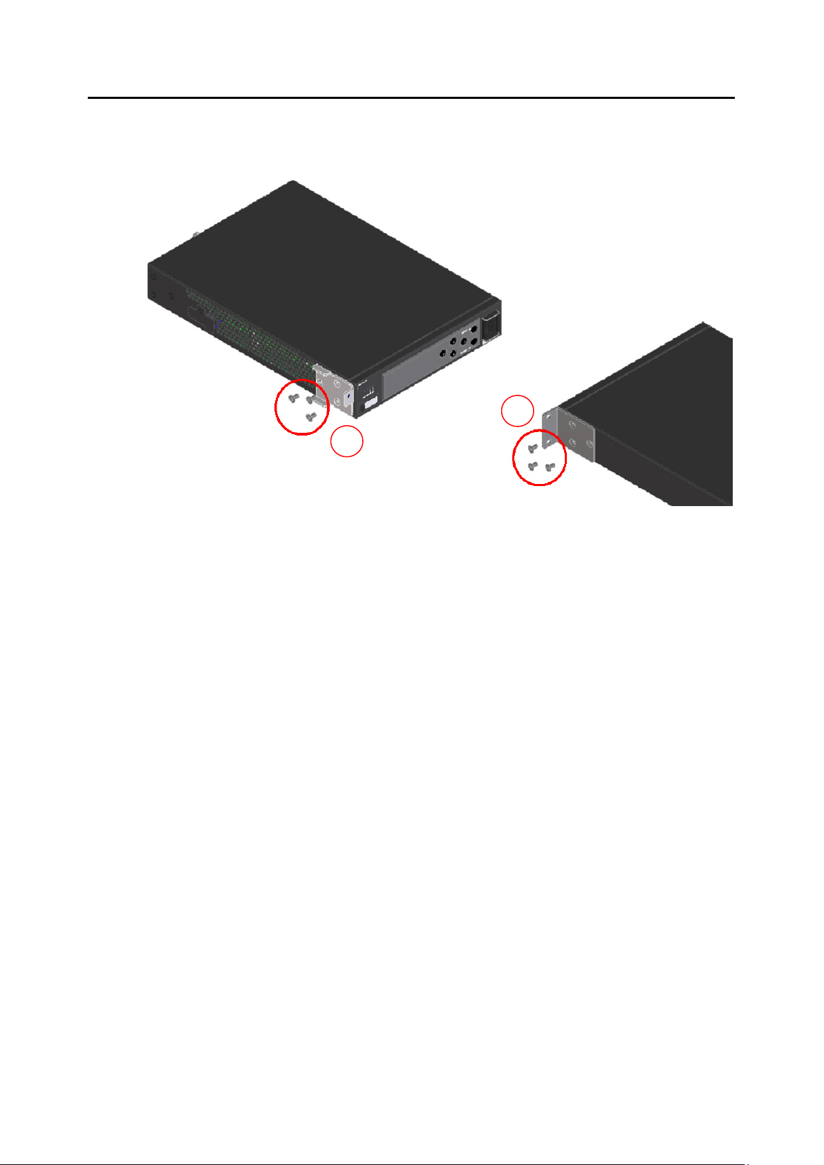
(4) Attach rack mounting brackets A and B to the side of the second IP-HE950 too. Tighten
screws (M4) at the six places like with the first unit.
Copyright 2017 FUJITSU LIMITED
13
Page 28
IP-HE950 Hardware User's Guide Chapter 2 Installation and Connection
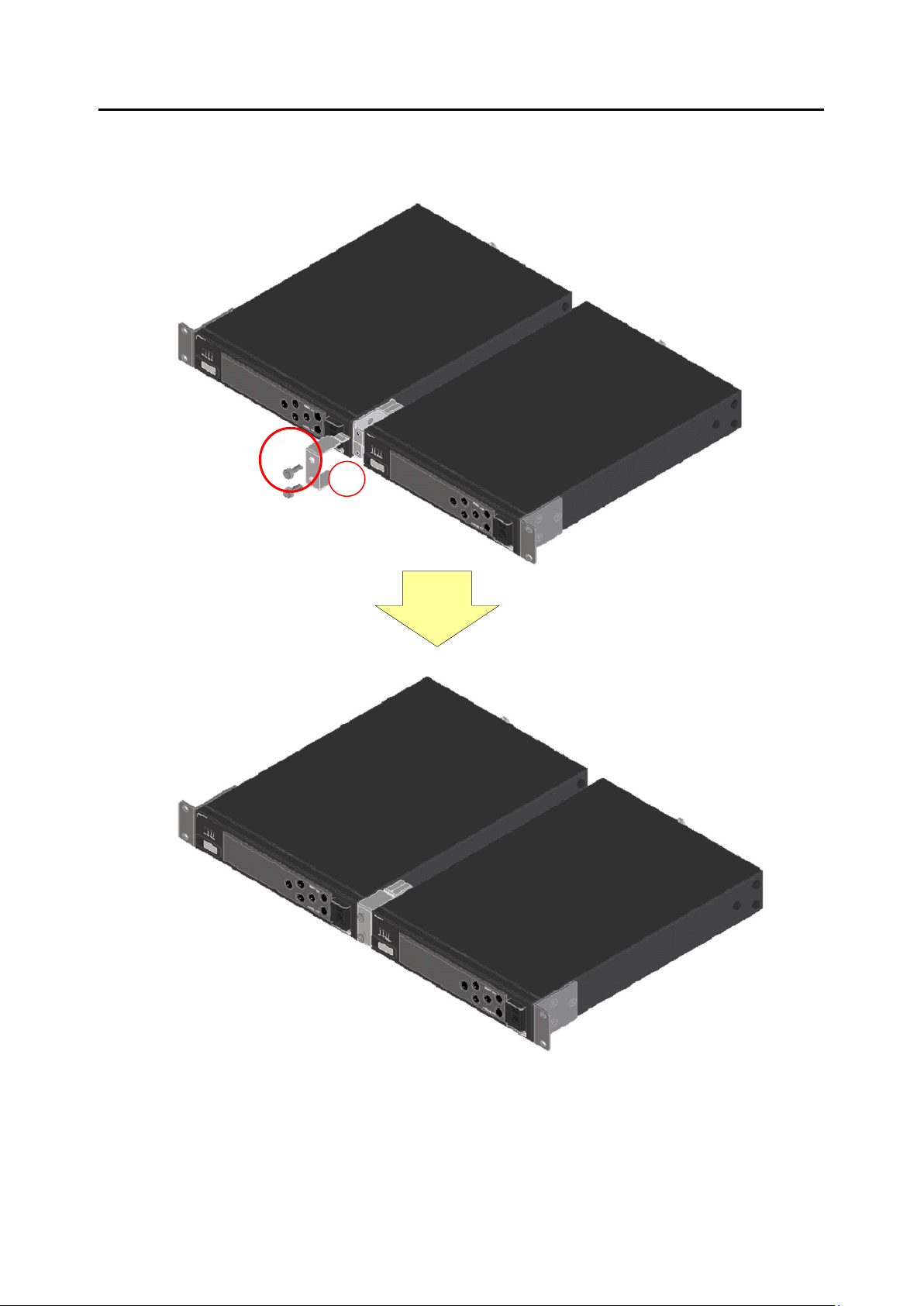
C
(5) Attach rack mounting bracket C to the IP-HE950.
Tighten pan head screws (M5) at the two places shown in the following figure.
.
Copyright 2017 FUJITSU LIMITED
14
Page 29

IP-HE950 Hardware User's Guide Chapter 2 Installation and Connection
D
D
(6) Align the units at specific positions in the 19" rack, and firmly secure the units in position
with the screws supplied with the rack mount option. Use four pan head screws (M5) to
secure them.
To secure the units to a server rack, use the cage nuts (D) and bind head screws (M6)
supplied with the rack mount option.
Copyright 2017 FUJITSU LIMITED
15
Page 30

IP-HE950 Hardware User's Guide Chapter 2 Installation and Connection
C
- Removing the unit
(1) To remove two units at the same time
Remove both units by reversing the installation procedure.
(2) To remove only one unit
Remove screws at the four places shown in the following figure.
Remove mounting bracket C, and then remove the unit.
Copyright 2017 FUJITSU LIMITED
16
Page 31

IP-HE950 Hardware User's Guide Chapter 2 Installation and Connection
F E E
- Mounting one IP-HE950 per 1U (Type: A1)
(1) Confirm the components of the rack mount kit.
(2) Confirm that all cables are disconnected.
(3) Attach rack mounting bracket E to the side of the IP-HE950.
Tighten screws (M4) at the three places shown in the following figure.
Copyright 2017 FUJITSU LIMITED
17
Page 32

IP-HE950 Hardware User's Guide Chapter 2 Installation and Connection
F
(4) Attach rack mounting bracket F to the other side of the IP-HE950.
Tighten screws (M4) at the three places shown in the following figure.
(5) Align the unit at a specific position in the 19" rack, and firmly secure the unit in
position with the screws supplied with the rack mount option.
Use two pan head screws (M5) per mounting bracket (four screws in total).
- Removing the unit
Remove the unit by reversing the installation procedure.
Copyright 2017 FUJITSU LIMITED
18
Page 33

IP-HE950 Hardware User's Guide Chapter 2 Installation and Connection
2. Desktop installation
Affix the four rubber feet supplied with this unit to the marked places for rubber feet on the
bottom of the unit.
For information on the installation space, refer to "2.1.4 Installation space."
Figure 2-1 Places for rubber feet
CAUTION
1) Multi-unit installation
When used in an environment where the intake temperature and ambient
temperature do not exceed 55°C, the IP-HE950 can be stacked on up to five
tiers, according to the strength of the unit.
Install them considering workability and maintainability. In addition, in a
multi-unit installation, be sure to secure each unit with a belt or other means
to prevent it from falling out and prevent toppling.
For information on the installation space, refer to "2.1.4 Installation space."
Copyright 2017 FUJITSU LIMITED
19
Page 34

IP-HE950 Hardware User's Guide Chapter 2 Installation and Connection
2) Rack mounting
When this unit is mounted and operates in a rack, the ambient
temperature of the unit inside the rack may be hotter than the ambient
temperature of the room.
Take care that the ambient temperature inside the rack does not exceed
the guaranteed operating temperature of this unit. The guaranteed
operating temperature of the unit is 55°C.
When mounting this unit to operate in a rack, allocate the intake/exhaust
space described in "2.1.4 Installation space."
When mounting this unit in a rack, use the dedicated mount kit to secure
it firmly to the rack.
In addition, if mounting the unit in the rack could make the whole rack
unstable, do not mount it.
The IP-HE950 weighs 2.5 kg.
When mounting two IP-HE950 per 1U with dedicated mount kit, do not
leave one unit after removing another unit. This may cause deformation of
mount kit.
Confirm that the power supply capacity of the power strips and service
outlets in the rack, which supply power to this unit, exceeds the total
power rating of all the equipment connected in the rack.
The power rating of this unit is as follows:
- IP-HE950E: 100 to 240 VAC, 50/60 Hz, single-phase, 0.93 to 0.53 A
- IP-HE950D: 100 to 240 VAC, 50/60 Hz, single-phase, 0.89 to 0.51 A
High leakage current may flow through the power strip grounding
conductor when the IP-HE950 power cord is connected to the power strip.
Be sure to connect to ground before connecting the power supply line.
If the power cord is not directly connected to a branch circuit, use a
power strip that has an industrial grade plug.
Copyright 2017 FUJITSU LIMITED
20
Page 35

IP-HE950 Hardware User's Guide Chapter 2 Installation and Connection
2.1.3 Intake and exhaust
The IP-HE950 is a forced air cooled unit. Take care not to block the intake/exhaust vents. Leave
an adequate amount of space around the vents.
2.1.4 Installation space
Allocate the operation space, cable bundle space, and intake/exhaust space shown as the
hatched areas in the following figure. (The space is always required.)
This installation space doesn’t show maintenance area.
Figure 2-2 Space required for an installation
21
Copyright 2017 FUJITSU LIMITED
Page 36

IP-HE950 Hardware User's Guide Chapter 2 Installation and Connection
2.2 Power Supply Connections
2.2
This section describes ground and power source connections. The descriptions are common to
the IP-HE950E and IP-HE950D.
2.2.1 Connection to ground
Use the power cord with a standard three-prong plug to connect FG and external ground (type
D (type 3) or better).
You can use the FG terminal for functional grounding to suppress external noise, etc.
Connect the FG terminal (M4 screw) to external ground.
Figure 2-3 Ground connection
Copyright 2017 FUJITSU LIMITED
22
Page 37

IP-HE950 Hardware User's Guide Chapter 2 Installation and Connection
2.2.2 Connection to a power source
Plug the AC power cord into the power inlet connector.
* Refer to "4.2 Cable and Connector Details," and select power cord. You can procure a power
cord separately by specifying the length.
- Mounting the AC cord clamp
Insert the AC cord clamp into the mounting hole, and secure the power cord to the AC
cord clamp, which prevents the power cord from falling out.
Figure 2-4 Power cord connection
23
Copyright 2017 FUJITSU LIMITED
Page 38

IP-HE950 Hardware User's Guide Chapter 2 Installation and Connection
- Removing the AC cord clamp
To remove the AC cord clamp, squeeze together the tabs of the AC cord clamp between
your fingers as indicated by the red arrows, and remove the AC cord clamp.
Figure 2-5 Removing the AC cord clamp
24
Copyright 2017 FUJITSU LIMITED
Page 39

IP-HE950 Hardware User's Guide Chapter 2 Installation and Connection
WARNING
CAUTION
Possibility of electric shock, fire, and damage to this unit
Always observe the precautions given below.
There may be a hazardous situation that could lead to electric shock, fire, and
damage to this unit.
Always connect the power cord to a power receptacle for a standard three-prong plug.
The AC power cord supplied with the unit for Japan domestic supports voltages up to
the rated voltage of 125 V. To use the IP-HE950 outside of Japan, refer to item (6) in
"4.2 Cable and Connector Details," and select another power cord.
Connect the IP-HE950 to a power receptacle with a capacity of 1 A or more. When
using a power extension cable, be sure that the total current consumption of all
equipment connected to the cable does not exceed the rated capacity of the cable. If a
power receptacle with a low capacity or capacity below the rated value is used, the
power receptacle, extension cable, or power wiring may overheat and start a fire.
Possibility of damage to this unit
Do not turn on the IP-HE950 peripherals have been connected successfully.
Otherwise, this unit may be damaged.
Copyright 2017 FUJITSU LIMITED
25
Page 40

IP-HE950 Hardware User's Guide Chapter 2 Installation and Connection
See
2.3 Connection to SDI Equipment
2.3
This section describes connection to SDI equipment.
2.3.1 Connection to SDI output equipment
Connect SDI output equipment to the SDI input of the IP-HE950E (encoder).
Connect a BNC cable to the SDI-IN connector of the IP-HE950E.
The following figure shows how to connect SDI output.
For details on connectors and cables, refer to "4.2 Cable and Connector
Details." For electrical specifications, refer to "A.2.3 Interface
specifications."
Figure 2-6 SDI output equipment connection
Copyright 2017 FUJITSU LIMITED
26
Page 41

IP-HE950 Hardware User's Guide Chapter 2 Installation and Connection
See
2.3.2 Connection to SDI input equipment
Connect SDI input equipment to the SDI output of the IP-HE950D (decoder).
Connect a BNC cable to the SDI-OUT connector of the IP-HE950D. A signal is terminated with
75 Ω.
The following figure shows how to connect SDI input equipment.
For details on connectors and cables, refer to "4.2 Cable and Connector
Details." For electrical specifications, refer to "A.2.3 Interface
specifications."
Figure 2-7 SDI input equipment connection
Copyright 2017 FUJITSU LIMITED
27
Page 42

IP-HE950 Hardware User's Guide Chapter 2 Installation and Connection
See
2.4 Connection to External Sync Signals (REF)
2.4
The IP-HE950D (decoder) has one input connector and one output connector for connection
with external sync signals (REF).
Sync signal input
Connect a BNC cable to the REF-IN connector of this unit. Enter an external sync signal. The
signal is terminated with 75 Ω.
Sync signal output
Connect a BNC cable to the REF-OUT connector of this unit. Output an external sync signal.
The signal is terminated with 75 Ω.
For details on connectors and cables, refer to "4.2 Cable and Connector
Details." For electrical specifications, refer to "A.2.3 Interface specifications."
Figure 2-8 External sync input/output unit connections
Copyright 2017 FUJITSU LIMITED
28
Page 43

IP-HE950 Hardware User's Guide Chapter 2 Installation and Connection
See
2.5 Connection to DVB-ASI Equipment
2.5
This section describes connection to DVB-ASI equipment.
2.5.1 Connection to DVB-ASI input equipment
Connect DVB-ASI equipment to the ASI output connector of the IP-HE950E (encoder).
Connect a BNC cable to ASI-OUT1 or ASI-OUT2 of the IP-HE950E.
The following figure shows how to connect them.
For details on connectors and cables, refer to "4.2 Cable and Connector
Details." For electrical specifications, refer to "A.2.3 Interface
specifications."
Figure 2-9 DVB-ASI input equipment connections
Copyright 2017 FUJITSU LIMITED
29
Page 44

IP-HE950 Hardware User's Guide Chapter 2 Installation and Connection
See
2.5.2 Connection to DVB-ASI output equipment
Connect DVB-ASI output equipment to the ASI input connector of the IP-HE950D
(decoder).
Connect a BNC cable to ASI-IN of the IP-HE950D. A signal is terminated with 75 Ω.
The following figure shows how to connect them.
For details on connectors and cables, refer to "4.2 Cable and Connector
Details." For electrical specifications, refer to "A.2.3 Interface
specifications."
Figure 2-10 DVB-ASI output equipment connection
Copyright 2017 FUJITSU LIMITED
30
Page 45

IP-HE950 Hardware User's Guide Chapter 2 Installation and Connection
See
2.6 Connection to LAN Equipment
2.6
This section describes connection of the IP-HE950 to LAN equipment. The descriptions are
common to the IP-HE950E and IP-HE950D.
To connect the IP-HE950 to LAN equipment, prepare a LAN cable to connect to a LAN port
(LAN1/LAN2).
The LAN port specifications of the IP-HE950 are 10BASE-T, 100BASE-TX, and 1000BASE-T.
This unit has two LAN ports, LAN1 and LAN2. Both are dual-purpose ports for streams and
settings.
The following figure shows how to connect them.
For details on connectors and cables, refer to "4.2 Cable and Connector Details."
For electrical specifications, refer to "A.2.3 Interface specifications."
Figure 2-11 LAN connections
Copyright 2017 FUJITSU LIMITED
31
Page 46

IP-HE950 Hardware User's Guide Chapter 2 Installation and Connection
CAUTION
Do not set the IP addresses shown below, when setting an IP address.
Setting conditions disabling a LAN port
- Generally unused (disabled) IP address (0.0.0.0, 255.255.255.255, etc.)
- Loopback address (127.xxx.xxx.xxx)
- Class D or Class E IP address
- IP address that conflicts with a LAN port network address
For details, refer to the IP-HE950 Software User's Guide.
32
Copyright 2017 FUJITSU LIMITED
Page 47

IP-HE950 Hardware User's Guide Chapter 2 Installation and Connection
See
side
2.7 Connection to Quad Link 3G-SDI Equipment
2.7
This section describes connection of the IP-HE950 to 4K video equipment for Quad Link 3G-SDI
input and output. The descriptions are common to the IP-HE950E and IP-HE950D.
To connect the IP-HE950 to 4K video equipment, prepare an SFP module (option), a Quad
3G-SDI conversion cable (option), and an SDI cable to connect the equipment to an SFP port
(SFP1/SFP2).
* The Quad 3G-SDI input option and the Quad 3G-SDI conversion cable option need to be
procured separately for the IP-HE950E. The Quad 3G-SDI output option and the Quad 3G-SDI
conversion cable option need to be procured separately for the IP-HE950D.
For details on connectors and cables, refer to "4.2 Cable and Connector
Details." For electrical specifications, refer to "A.2.3 Interface
specifications."
- Example of connection of the IP-HE950E to 4K video equipment for Quad Link 3G-SDI
output
SFP1-1 SFP2-1
SFP1-2 SFP2-2
Quad 3G-SDI input option (encoder):
‘▲’ faces to the unit side
For decoder
Quad 3G-SDI output option
(decoder):
‘▲’ faces to HD-BNC connector
Figure 2-12 Connections to 4K video output equipment
Dual 3G-SDI
input SFP
Quad 3G-SDI
conversion cable
SDI cable
4K video output equipment
Unlock mechanism
Copyright 2017 FUJITSU LIMITED
33
Page 48

IP-HE950 Hardware User's Guide Chapter 2 Installation and Connection
Be sure to turn off the power and then unplug the power cord before installing or removing an
SPF module, which is a hardware option. In addition, when connecting this unit with a
conversion cable, pay special care and attention to not damage the conversion cable.
The SFP module has a lock mechanism. Firmly insert the module until it locks. When removing
the module, hold down the unlock mechanism. Never forcibly remove the module because that
may cause damage.
For instructions on configuring and using the SFP module, refer to the IP-HE950 Software
User's Guide.
- Removing SFP module
When removing the SFP module, press the unlock mechanism in the direction indicated
by the red arrow shown in the following figure with the Quad 3G-SDI conversion cable left
connected. Keep holding down the unlock mechanism as you pull the SFP module
straight out of the unit.
(1) Unlock the lock.
(2) Pull the SFP module straight out of the unit.
Figure 2-13 Removing an SFP module
34
Copyright 2017 FUJITSU LIMITED
Page 49

IP-HE950 Hardware User's Guide Chapter 3 Operation Instructions
Operation Instructions
Chapter 3
Chapter 3 Operation Instructions
This section describes how to operate this unit.
3.1 Turning On/Off the IP-HE950 ························································ 36
3.2 Unit Settings and Operation (WEB) ··············································· 37
3.3 Unit Settings and Operation (Front Panel) ······································· 38
3.4 Special Use of the CANCEL Key ··················································· 39
35
Copyright 2017 FUJITSU LIMITED
Page 50

IP-HE950 Hardware User's Guide Chapter 3 Operation Instructions
-
Set the switch to this position to turn on the IP-HE950.
O
Set the switch to this position to turn off the IP-HE950.
3.1 Turning On/Off the IP-HE950
3.1
This section describes how to turn on and off the IP-HE950. The descriptions are common to the
IP-HE950E and IP-HE950D.
3.1.1 Turning on the IP-HE950
Set the power switch on the front panel to the [-] position to turn on the power, which turns on
the PWR LED.
The RDY LED goes on when the IP-HE950 is ready.
Figure 3-1 Front view of the unit
3.1.2 Turning off the IP-HE950
Set the power switch on the front panel to the [O] position to turn off the power, which turns off
the PWR LED.
36
Copyright 2017 FUJITSU LIMITED
Page 51

IP-HE950 Hardware User's Guide Chapter 3 Operation Instructions
IP address
3.2 Unit Settings and Operation (WEB)
3.2
- Setup procedure
The following figure shows the setup procedure of this unit. The procedure is common to the
IP-HE950E and IP-HE950D.
For each setting, refer to the software user's guide.
- Recommended Web browser
About the supported Web browsers, refer to the software user’s guide.
37
Copyright 2017 FUJITSU LIMITED
Page 52

IP-HE950 Hardware User's Guide Chapter 3 Operation Instructions
3.3 Unit Settings and Operation (Front panel)
3.3
This unit is equipped with six operation keys: [ ], [ ], [ ], [ ], [ENTER], and [CANCEL].
Use these keys to configure settings.
The front panel has a display of 22 characters x 4 lines.
For front panel operation and display instructions, refer to the IP-HE950 Software User's
Guide.
Figure 3-2 Front panel and operation keys
- Functional description of each key
[ ] and [ ] key functions
- Switches the menu items and setting items displayed on the front panel.
- Switches the displayed items with each press of a key. [ ] and [ ] switch the
displayed items in opposite directions.
[ ] and [ ] key functions
- Used to move the cursor displayed on the front panel to the right or left.
- Moves the cursor by one place with each press of a key.
[ENTER] key
- When the initial maintenance screen is displayed, pressing the [ENTER] key causes a
transition to the maintenance menu screen.
- Pressing the [ENTER] key from the maintenance menu screen allows you to display the
status and configure the shutdown settings.
[CANCEL] key
- When the maintenance menu screen is displayed, pressing the [CANCEL] key causes a
transition to the initial maintenance screen. Pressing the [CANCEL] key from the setting
item selection screen causes a transition to the screen immediately before the last
[ENTER] key operation.
Other
- In addition, on every screen, if 60 seconds elapse without input from any key, the
screen transitions to the initial screen.
38
Copyright 2017 FUJITSU LIMITED
Page 53

IP-HE950 Hardware User's Guide Chapter 3 Operation Instructions
3.4 Special Use of the CANCEL Key
3.4
Start the IP-HE950 by holding down the [CANCEL] key during the power-on operation.
When you hold down the key until the RDY LED begins blinking in orange, the IP-HE950
starts with the factory default values for the IP address and subnet mask (LAN1: IP address
10.0.0.1 and subnet mask 255.0.0.0; LAN2: IP address 192.168.255.253 and subnet mask
255.255.255.252).
Use this feature to initialize the unit settings from a control terminal (e.g., PC with a LAN
interface).
(Note 1) To operate the IP-HE950 with the default IP address, connect it to a control
terminal and configure settings with it disconnected from your network.
After configuring settings appropriate to your network, connect it to the network. If
connected as is with the factory default settings, the unit may cause an
unexpected problem to occur in the network.
After starting the IP-HE950 while holding down the [CANCEL] key, set the
following IP addresses and subnet masks for the control terminal to be connected:
- LAN1 IP address: 10.xxx.xxx.xxx
(xxx is any number from 0 to 255, except for 10.0.0.0, 10.0.0.1, 10.0.0.2, and
10.255.255.255.)
- LAN1 subnet mask: 255.0.0.0
- LAN2 IP address: 192.168.255.254
- LAN2 subnet mask: 255.255.255.252
39
Copyright 2017 FUJITSU LIMITED
Page 54

IP-HE950 Hardware User's Guide Chapter 4 Cable Specifications
Chapter 4 Cable Specifications
Cable Specifications
Chapter 4
This chapter describes the scope of IP-HE950 installation work and
contains cable connection system diagrams and cable and
connector details.
4.1 Installation Preparations ······························································ 41
4.2 Cable and Connector Details ························································ 43
40
Copyright 2017 FUJITSU LIMITED
Page 55

IP-HE950 Hardware User's Guide Chapter 4 Cable Specifications
4.1 Installation Preparations
4.1
The following figure shows the scope of procurement for IP-HE950 installation work. The
indicators for the cables connected to 4K video output equipment are also shown below.
Figure 4-1 Procurement scope for IP-HE950E installation work
41
Copyright 2017 FUJITSU LIMITED
Page 56

IP-HE950 Hardware User's Guide Chapter 4 Cable Specifications
Figure 4-2 Procurement scope for IP-HE950D installation work
In the construction of a system that uses the IP-HE950, the demarcation line between the
IP-HE950 and other equipment is generally like that in the above figure. Despite that, in actual
construction, procure equipment and perform installation work in consultation with the system
designer in charge.
42
Copyright 2017 FUJITSU LIMITED
Page 57

IP-HE950 Hardware User's Guide Chapter 4 Cable Specifications
4.2 Cable and Connector Details
4.2
The following figures show the cables and connectors available for this unit.
(1) SDI cable
(2) DVB-ASI cable
Figure 4-3 SDI cable
Figure 4-4 DVB-ASI cable
43
Copyright 2017 FUJITSU LIMITED
Page 58

IP-HE950 Hardware User's Guide Chapter 4 Cable Specifications
(3) LAN interface connection cable
Figure 4-5 LAN interface connection cable
Copyright 2017 FUJITSU LIMITED
44
Page 59

IP-HE950 Hardware User's Guide Chapter 4 Cable Specifications
(4) Sync signal (REF) cable
Figure 4-7 Sync signal (REF) cable
(5) AC power cord (supplied with the unit for Japan domestic, rated voltage of 125 or less)
The following figure shows the cord for 100 VAC input.
Figure 4-8 AC power cord
* The AC power cord supplied with the unit supports voltages up to the rated voltage of 125 V.
To use the IP-HE950 above the rated voltage of 125 V, refer to (6) and select another power
cord.
45
Copyright 2017 FUJITSU LIMITED
Page 60

IP-HE950 Hardware User's Guide Chapter 4 Cable Specifications
(6) AC power cord (rated voltage of 125 V or more)
Use a cord that satisfies the following conditions:
- Meets the following ratings:
[Connector] IEC 60320 C-13/15 A/250 V
[Cord] Diameter: 0.75 mm
2
or more; Length: 4.5 m or less; Allowable current: 8 A or more;
Rating: 300 V or more
[Plug] NEMA 6-15P/15 A/250 V
- Certified under the pertinent electrical appliance and material safety law (In Japan, the
connector, cord, and plug each has to have the PSE mark.)
(7) Quad 3G-SDI conversion cable
Figure 4-9 Quad 3G-SDI conversion cable
46
Copyright 2017 FUJITSU LIMITED
Page 61

IP-HE950 Hardware User's Guide Chapter 5 Troubleshooting
Chapter 5 Troubleshooting
Troubleshooting
Chapter 5
This chapter describes the actions to take if, for example, this unit
does not operate normally or if an alarm LED goes on.
5.1 Help Information ········································································ 48
5.2 Alarm LED Goes On ··································································· 55
5.3 Maintenance ············································································· 56
47
Copyright 2017 FUJITSU LIMITED
Page 62

IP-HE950 Hardware User's Guide Chapter 5 Troubleshooting
Is the power cord connected?
Check whether the power cord is properly connected to
Is the outlet voltage normal?
Measure the voltage with a tester to confirm that the
A unit error occurred.
Check the alert code from the log information screen for
E020 FAN error
E090 Memory error
Contact Fujitsu sales or Fujitsu partners. The center
35 below.
E042/E043 Temperature error
Check whether the unit installation environment
may have occurred.
An error in unit settings/performance or a
Check the alert code from the log information screen for
corrective action.
E010 VFD Device error
Contact Fujitsu sales or Fujitsu partners.
E040/E041 Temperature warning
Check whether the unit installation environment
may have occurred.
* Default settings
5.1 Help Information
5.1
If you find a problem in unit operation, take the corresponding corrective action in the table
below, according to the applicable conditions.
After the installation of software, refer to Table 5.1, "Check details and corrective actions" in the
IP-HE950 Software User's Guide.
If the problem persists even after you take corrective action, contact a Fujitsu Service Center.
WARNING
Possibility of electric shock
Contact your system administrator before checking the voltage of a
power outlet. Otherwise, electric shock may occur.
Tab le 5-1 Check details and corrective actions (IP-HE950E)
No. Class Status Check Corrective action
1
The unit
cannot be
Power
2
powered on.
the outlet.
voltage is normal.
If another unit is connected to the same outlet, check
the operation of the unit.
settings on the Web GUI. The code indicates the
corrective action.
3
4
The ALM LED
is on.
Unit
The ALM LED
is blinking.
E030 Power supply error
E044/E045 Temperature sensor
communication error
E050-E070 Clock error
part is indicated.
generated
may ask you about the alert code. Check the alert code
from the log information screen for settings on the Web
GUI.
If an SFP-type alert code is output, refer to items 32 to
satisfies "2.1 Installation Conditions."
- Is there enough space around intake/exhaust
openings?
- Is the ambient temperature within the range of
environmental conditions?
If there is a problem in the above installation conditions,
eliminate the problem. Then, reboot the unit.
If there is no problem in installation conditions, contact
Fujitsu sales or Fujitsu partners because a unit failure
settings on the Web GUI. The code indicates the
satisfies "2.1 Installation Condition."
- Is there enough space around intake/exhaust
openings?
- Is the ambient temperature within the range of
environmental conditions?
If there is a problem in the above installation conditions,
eliminate the problem. Then, reboot the unit.
If there is no problem in installation conditions, contact
Fujitsu sales or Fujitsu partners because a unit failure
48
Copyright 2017 FUJITSU LIMITED
Page 63

IP-HE950 Hardware User's Guide Chapter 5 Troubleshooting
Is the audio/video output unit selected as
Check the power supply and the operation of the
Is this unit correctly connected to the
Confirm that the connection between this unit and the
Does the set input audio/video format on
input.)
Check whether your preferred audio/video format is set
Does the set input audio/video format on
50 Hz.)
Check whether your preferred audio/video format is set
Is the monitor connected to the decoder
operating normally?
Check the operation of the monitor.
Is the decoder operating normally?
Check the operation of the decoder.
Is the decoder correctly connected to the
Check the connection between the decoder and the
Has an alert been generated on the
If so, refer to the user's guide of the decoder or other
Does the decoder display color bars or a
before performing the operation.)
If color bars or a gray screen appears, the network and
Is the RDY LED blinking in green?
The unit is booting up.
Wait until the RDY LED turns green.
Is the RDY LED blinking in orange?
The unit started in maintenance mode.
Restart the unit.
Is the ALM LED blinking?
The blinking ALM LED may indicate an IP address
details, refer to the IP-HE950 Software User's Guide.)
Has encoding begun?
Set the encoder to start encoding.
Can the paired unit (decoder) start
encoding?
Set the decoder to start decoding.
Are the Stream out settings correct?
Referring to the IP-HE950 Software User's Guide,
this unit and the encoder.
Is the network operating normally?
Refer to the "Network" section in this table.
No. Class Status Check Recommended action
5
6
7
8
9
10
11
The INDWN
LED lights up
in orange.
The INDWN
LED is blinking
in orange.
No video is
output at the
Video
decoder.
(Black screen)
input (e.g., camera) operating normally?
audio/video output unit?
(Example: Analog signals are connected to
the SDI signal input of this unit.)
this unit match the format of the
audio/video output unit (e.g., camera)?
(Example: Although 2160p is the input
setting on this unit, 1080p signals are
this unit match the format of the
audio/video output unit (e.g., camera)?
(Example: Although 59.94 Hz is the input
setting on this unit, the output unit is set to
monitor?
decoder?
audio/video output unit selected as input.
audio/video output unit is correct, and check for
problems in the cable.
as the format of this unit and the format of the output
unit.
as the format of this unit and the format of the output
unit.
monitor.
such documents, and take corrective action.
gray screen when nothing is input to the
12
13
14
15
16
17
18
19
The monitor of
the decoder
displays an all
blue or gray
screen.
video input of this unit? (Note that this
operation generates INDVN. Confirm that
there will be no operational problems
the decoder seem to be operating normally. Confirm the
correct video input to this unit.
acquisition failure. Check the IP address setting. (For
check whether the Stream out settings are correct on
49
Copyright 2017 FUJITSU LIMITED
Page 64

IP-HE950 Hardware User's Guide Chapter 5 Troubleshooting
Has a packet loss occurred at the decoder?
If you could confirm a packet loss occurrence, check
Is "No audio" selected in the audio format
settings of this unit?
Select an option other than "No audio" to set the
encoding of audio.
Is the decoder turned on?
Check the paired unit (decoder) power and operation.
Is the decoder correctly connected to the
Check the connection between the decoder and the
Has an alert been generated on the
If so, refer to the user's guide of the paired unit
Disconnect the audio input cable from this
If noise disappears when the cable is disconnected, the
Is the decoder operating normally?
If the noise does not disappear even after the network
Has a packet loss occurred at the decoder?
If you could confirm a packet loss occurrence, check
No. Class Status Check Corrective action
the following issues.
- Does the system rate setting exceed the transmission
capability of the connected network?
- Is the FEC/ARQ function properly set on both this unit
and the decoder?
- Are the network equipment and LAN port settings
(AUTO, fixed mode, etc.) different?
20
21
Video/Audio
output from the
decoder is
distorted.
22
23
24
25
26
27
No sound
comes out from
the decoder.
Audio
Noise is
generated on
the decoder.
audio speaker?
decoder?
unit. Does that eliminate the noise?
audio speaker.
(decoder).
noise seems to be mixed into the audio signal input.
Check the audio output equipment.
cable is disconnected from the decoder, this unit seems
to be operating normally. Check the decoder.
the following issues.
- Does the system rate setting exceed the transmission
capability of the connected network?
- Is the FEC/ARQ function properly set on both this unit
and the decoder?
- Are the network equipment and LAN port settings
(AUTO, fixed mode, etc.) different?
50
Copyright 2017 FUJITSU LIMITED
Page 65

IP-HE950 Hardware User's Guide Chapter 5 Troubleshooting
Is the connected network equipment (e.g.,
Check the power and operation of the connected
Is this unit correctly connected to network
Confirm that there is no problem with the LAN cable
(disconnected, or poorly connected).
Is the correct IP address specified in the
Set the correct IP address from a Web browser on the
Are network settings (IP address, subnet
Set the correct values. If this unit started with the
Issue a PING command to the IP address of
If there is no response, turn on the IP-HE950E while
Is the SFP module correctly mounted?
The SFP module may be incorrectly mounted. Firmly
occurred. Contact Fujitsu sales or Fujitsu partners.
type
Is there a conflict between the SFP module
The functions on the SFP module may not match unit
Contact Fujitsu sales or Fujitsu partners.
The surface temperature of the SFP module
The ambient temperature of the unit seems to be
sales or Fujitsu partners.
The SFP module voltage is abnormal.
The SFP module voltage is abnormal and an SFP
No. Class Status Check Corrective action
28
29
30
31
32
33
34
The LINK/ACT
LED of a LAN
port does not
go on.
Network
The unit cannot
be set via a
LAN.
E900/EA00
(SFP1/2 not
mounted)
E910/EA10
(SFP1/2
connectionerror)
hub or router) operating normally?
equipment (e.g., hub or router)?
Web browser?
mask, etc.) correct on the control PC?
this unit. Does it respond?
and unit settings?
network equipment (e.g., hub or router).
destinations/connection itself (mating defect, or
connection mistake) and the LAN cable itself
control PC.
factory default settings, refer to "3.2 Unit Settings and
Operation" for the network settings on the control PC.
pressing the CANCEL key for startup in maintenance
mode with the factory default IP address (10.0.0.1)
setting. If the problem persists, check the operating
status on the LAN.
insert the SFP module until you hear a click.
If this alert is still generated after you confirmed that the
SFP module is correctly mounted, replace it with a
neighboring SFP module. If the alert moves to the
neighboring module, an SFP module failure may have
settings. Check the mounted SFP module to confirm
that the unit settings match the functions.
(Is output SFP module mis-inserted?)
If this alert is still generated after you confirmed the
correct settings, replace the SFP module with a
neighboring one. If the alert moves to the neighboring
module, an SFP module failure may have occurred.
SFP
E920/EA20
35
36
(Abnormal
SFP1/2
temperature)
E930/EA30
(Abnormal
SFP1/2
voltage)
is higher than the reference value.
higher than the reference value. Cool the ambient
temperature to the unit operating conditions. In
addition, confirm that the intake space stated in the
installation conditions has been allocated.
If this alert is still generated after you confirmed the
correct ambient temperature condition and the intake
space, replace the SFP module with a neighboring one.
If the alert moves to the neighboring module, an SFP
module failure may have occurred. Contact Fujitsu
module failure may have occurred. Replace the SFP
module with a neighboring one. If this alert moves to
the neighboring module, an SFP module failure may
have occurred. Contact Fujitsu sales or Fujitsu
partners.
51
Copyright 2017 FUJITSU LIMITED
Page 66

IP-HE950 Hardware User's Guide Chapter 5 Troubleshooting
Is the power cord connected?
Check whether the power cord is properly connected to
Is the outlet voltage normal?
Measure the voltage with a tester to confirm that the
A unit error occurred.
Check the alert code from the log information screen for
E020 FAN error
E090 Memory error
Contact Fujitsu Sales or a Fujitsu partner. The center
29.
E042/E043 Temperature error
Check whether the unit installation environment satisfies
may have occurred.
An error in unit settings/performance or a
Check the alert code from the log information screen for
E010 VFD Device error
Contact Fujitsu sales or Fujitsu partners.
E040/E041 Temperature warning
Check whether the unit installation environment satisfies
may have occurred.
Is the connected monitor operating
normally?
Check the operation of the monitor.
Is this unit turned on?
Confirm that the PWR LED of this unit is on.
Is this unit correctly connected to the
monitor?
Check the connection between this unit and the monitor.
Is the correct video output setting
Confirm that monitor display is enabled in the video
Is the ALM LED on?
Refer to item 3 in this table.
Are color bars or a gray screen displayed
operation.)
If color bars or a gray screen appears, the network and
Tab le 5-2 Check details and corrective actions (IP-HE950D)
No. Class Status Check Corrective action
1
The unit
cannot be
Power
2
3
powered on.
E030 Power supply error
E044/E045 Temperature sensor
communication error
E050-E070 Clock error
The ALM LED
is on.
Unit
part is indicated.
the outlet.
voltage is normal.
If another unit is connected to the same outlet, check the
operation of the unit.
settings on the Web GUI. The code indicates the
corrective action.
may ask you about the alert code. Check the alert code
from the log information screen for settings on the Web
GUI.
If an SFP-type alert code is output, refer to items 26 to
"2.1 Installation Conditions."
- Is there enough space around intake and exhaust
openings?
- Is the ambient temperature within the range of
environmental condition?
If there is a problem in the above installation conditions,
eliminate the problem. Then, reboot the unit.
If there is no problem in installation conditions, contact
Fujitsu sales or Fujitsu partners because a unit failure
settings on the Web GUI. The code indicates the
corrective action.
4
5
6
7
8
9
10
The ALM LED
is blinking.
No video is
output.
Video
(Black screen)
specified on this unit?
when nothing is input to the video input of
the encoder? (Note that this operation
generates INDWN on the encoder.
Confirm that there will be no operational
problems before performing the
generated
"2.1 Installation Conditions."
- Is there enough space around intake/exhaust
openings?
- Is the ambient temperature within the range of
environmental conditions?
If there is a problem in the above installation conditions,
eliminate the problem. Then, reboot the unit.
If there is no problem in installation conditions, contact
Fujitsu sales or Fujitsu partners because a unit failure
output settings of this unit.
this unit seem to be operating normally. Confirm the
correct video input to the encoder.
52
Copyright 2017 FUJITSU LIMITED
Page 67

IP-HE950 Hardware User's Guide Chapter 5 Troubleshooting
Is the RDY LED blinking in green?
This unit is booting up.
Is the RDY LED blinking in orange?
This unit started in maintenance mode.
Restart the unit.
Is the INDWN LED blinking in orange?
An error occurred in the received stream data. Confirm
equipment.
14
Is this unit turned on?
Check the power and operation of this unit.
Is "No audio" selected in the audio format
Select an option other than "No audio" to set the
Is this unit correctly connected to the audio
speaker?
Check the connection between this unit and the audio
speaker.
Is the ALM LED on?
Refer to item 3 in this table.
Disconnect the LAN cable. Does that
If the noise does not disappear even after the LAN cable
occurred on this unit.
Disconnect the audio input cable from the
If the noise disappears when the cable is disconnected,
to the encoder. Check the audio output equipment.
Has a packet loss occurred?
Refer to item 13 in this table.
Is the connected network equipment (e.g.,
Check the power and operation of the connected
Is this unit correctly connected to network
Confirm that there is no problem with the LAN cable
(disconnected, or poorly connected).
Is the correct IP address specified in the
Web browser?
Set the correct IP address from a Web browser on the
control PC.
Are network settings (IP address, subnet
Set the correct values. If this unit started with the factory
Issue a PING command to the IP address
If there is no response, turn on the IP-HE950D while
No. Class Status Check Corrective action
11
12
13
15
16
17
18
19
Video
Audio
Only a
blue/gray
screen
appears.
No sound
comes out.
Noise is
generated.
settings of the encoder?
eliminate the noise?
encoder. Does that eliminate the noise?
Wait until the RDY LED turns green.
the proper settings/proper operation on the connected
network and the encoder. Confirm that the DVB-ASI
signal connection is correct, and check for problems in
the cables.
(When using the reference function)
Check the reference signal output equipment, the
reference adapter conversion cable, and the reference
signal cable connected to the reference input terminal.
Check the format settings of the reference signal output
encoding of audio.
is disconnected from this unit, a failure may have
the noise seems to be mixed into the audio signal input
20
21
22
23
24
25
The LINK/ACT
LED of a LAN
port does not
go on.
Network
The unit cannot
be set via a
LAN.
hub or router) operating normally?
equipment (e.g., hub or router)?
mask, etc.) correct on the control PC?
of this unit. Does it respond?
network equipment (e.g., hub or router).
destinations/connection itself (mating defect, or
connection mistake) and the LAN cable itself
default settings, refer to "3.2 Unit Settings and
Operation" for the network settings on the control PC.
pressing the CANCEL key for startup in maintenance
mode with the factory default IP address (10.0.0.1)
setting. If the problem persists, check the operating
status on the LAN.
53
Copyright 2017 FUJITSU LIMITED
Page 68

IP-HE950 Hardware User's Guide Chapter 5 Troubleshooting
Is the SFP module correctly mounted?
The SFP module may be incorrectly mounted. Firmly
type
Is there a conflict between the SFP
The functions on the SFP module may not match unit
Contact Fujitsu sales or Fujitsu partners.
The surface temperature of the SFP
The ambient temperature of the unit seems to be higher
The SFP module voltage is abnormal.
The SFP module voltage is abnormal and an SFP
No. Class Status Check Corrective action
insert the SFP module until you hear a click.
If this alert is still generated after you confirmed that the
SFP module is correctly mounted, replace it with a
neighboring SFP module. If the alert moves to the
neighboring module, an SFP module failure may have
occurred. Contact Fujitsu sales or Fujitsu partners.
26
E900/EA00
(SFP1/2 not
mounted)
27
28
29
module and unit settings?
E910/EA10
(SFP1/2
connectionerror)
SFP
module is higher than the reference value.
E920/EA20
(Abnormal
SFP1/2
temperature)
E930/EA30
(Abnormal
SFP1/2
voltage)
settings. Check the mounted SFP module to confirm that
the unit settings match the functions.
(Is input SFP module mis-inserted?)
If this alert is still generated after you confirmed the
correct settings, replace the SFP module with a
neighboring one. If the alert moves to the neighboring
module, an SFP module failure may have occurred.
than the reference value. Cool the ambient temperature
to the unit operating conditions. In addition, confirm that
the intake space stated in the installation conditions has
been allocated.
If this alert is still generated after you confirmed the
correct ambient temperature condition and the intake
space, replace the SFP module with a neighboring one.
If the alert moves to the neighboring module, an SFP
module failure may have occurred. Contact Fujitsu sales
or Fujitsu partners.
module failure may have occurred. Replace the SFP
module with a neighboring one. If this alert moves to the
neighboring module, an SFP module failure may have
occurred. Contact Fujitsu sales or Fujitsu partners.
54
Copyright 2017 FUJITSU LIMITED
Page 69

IP-HE950 Hardware User's Guide Chapter 5 Troubleshooting
Blinks in green during preparation for operation, and lights up in green during
operation in maintenance mode.
Off during normal operation. The LED lights up or blinks in orange at the time
Software User's Guide.
Alarm LED. The LED lights up or blinks in orange when a unit alert is
User's Guide.
Status LED of the LAN1/2 port.
the cable is disconnected.
Linked speed indicator LED of the LAN1/2 port.
and blinks in operation with 1000BASE.
5.2 Alarm LED Goes On
5.2
This section describes the corrective actions to take if an alarm LED (ALM or INDWN) goes on.
The appropriate corrective action depends on the displayed alert code. For details, refer to the
IP-HE950 Software User's Guide.
The following table describes what is indicated by LEDs.
Tab le 5-3 LED indications
Display Description
PWR Lights up in green when the IP-HE950 is turned on.
operation.
RDY
INDWN
The LED blinks in orange during preparation to start up in maintenance mode
(Power-on while pressing the CANCEL key), and lights up in orange during
of a signal error or disconnection in the input system or network.
You can select to turn on, blink, or turn off this LED as the setting for some
alert indications.
For alert log check instructions and LED settings, refer to the IP-HE950
ALM
LINK/ACT
100/1000M
occurred.
You can select to turn on, blink, or turn off this LED as the setting for some
alert indications.
For alert log check instructions and LED settings, refer to IP-HE950 Software
The status LED goes on when a link is established and blinks when a LAN
packet is detected. The status LED goes off when the cable link goes down or
The LED is off in operation with 10BASE, is on in operation with 100BASE,
55
Copyright 2017 FUJITSU LIMITED
Page 70

IP-HE950 Hardware User's Guide Chapter 5 Troubleshooting
Desktop installation
1 m at the front or rear.
Rack mounting
at the front and rear.
IP-HE950
IP-HE950
IP-HE950
IP-HE950
Figure 5-2 Maintenance areas
(Rack mounting)
5.3 Maintenance
5.3
5.3.1 Maintenance area
The following figure shows the maintenance area required, in addition to that in "2.1.4
Installation space," for maintenance engineers.
Allocate a maintenance area of more than
Access from front
Access from rear
Figure 5-1 Maintenance areas
(Desktop installation)
Allocate a maintenance area of more than 1 m
56
Copyright 2017 FUJITSU LIMITED
Page 71

IP-HE950 Hardware User's Guide Chapter 5 Troubleshooting
5.3.2 Unit (maintenance part) replacement
If a failure occurs, check it in "5.1 Help Information," and take corrective action. After that, if
the situation does not improve, the unit can be assumed to have malfunctioned. Replace the
hardware according to the following procedure.
Figure 5-3 Unit
For the IP-HE950, the main unit itself is regarded as a repair unit.
If the unit malfunctions, replace the main unit itself.
5.3.3 SFP module (maintenance part) replacement
If a failure occurs, check it in "5.1 Help Information," and take corrective action. After that, if
the situation does not improve, refer to "5.3.4 Cable and SFP module removal procedures,"
and change the module.
5.3.4 Cable and SFP module removal procedures
The interface connectors of this unit are densely packed in any installation. Therefore, in an
installation in a 19" rack, for example, it may be difficult to take out cables and SFP modules.
In such cases, take out cables in the order that they can be disconnected.
When removing an SFP module, hold down the unlock mechanism while you pull it out directly.
Never forcibly remove the module because that may cause damage. For details, refer to "2.7
"Connection to Quad Link 3G-SDI Equipment."
57
Copyright 2017 FUJITSU LIMITED
Page 72

IP-HE950 Hardware User's Guide Appendix
Appendix
Appendix
The appendix contains views of this unit and lists its main
specifications. Precautions and other such notes on installation
work and on-site tune-up are also covered in this section.
A.1 Appearance ·············································································· 59
A.2 Main Specifications ···································································· 61
A.3 Installation Work ········································································ 69
A.4 On-Site Tune-Up Work ································································ 70
58
Copyright 2017 FUJITSU LIMITED
Page 73

IP-HE950 Hardware User's Guide Appendix
A.1 Appearance
A.1
A.1.1 IP-HE950E
The following figure shows the appearance of this unit.
Figure A.1-1 IP-HE950E appearance
Copyright 2017 FUJITSU LIMITED
59
Page 74

IP-HE950 Hardware User's Guide Appendix
A.1.2 IP-HE950D
The following figure shows the appearance of this unit.
Figure A 1-2 IP-HE950D appearance
60
Copyright 2017 FUJITSU LIMITED
Page 75

IP-HE950 Hardware User's Guide Appendix
Item
Specification
Installation
conditions
Indoor: Desktop installation or rack mounting
Can be mounted in 1U rack space (excluding rubber feet)
Dimensions
Width: 210 Height: 43 Depth: 300 (mm) * Excluding protrusions
Cooling
method
Power
100 to 240 VAC
Weight
Max. 2.5 kg
Power
consumption
Item
Specification
Power supply
conditions
Temperature
conditions
Temperature: -10 to 55°C (excluding low-temperature startup under 0°C)
(Conditions for guaranteed operation and guaranteed characteristics)
Dust
concentration
Communications equipment room or office environment (0.15 mg/m3 or
less)
Conforms to IEC 60721-3-3 Class 3C1
Nitrogen oxide (NO2) : Max. 0.052 cm3/m3
Electromagnetic
regulations
A.2 Main Specifications
A.2
This section lists the external specifications, environmental specifications, and interface
specifications of this unit.
A.2.1 External specifications
This unit has the external specifications shown below.
Tab le A.2-1 External specifications
Forced air cooling
IP-HE950E: 126 VA or less, IP-HE950D: 122 VA or less
A.2.2 Environmental specifications
This unit has the environmental specifications shown below.
Tab le A.2-2 Environmental specifications
100 to 240 VAC ±10%, 50/60 Hz ±3 Hz
and humidity
Allowable
concentration of
corrosive gas
interference
Humidity: 20 to 90% (no condensation)
Sulphur dioxide (SO2) : Max 0.037 cm3/m3
Hydrogen sulfide (H
Chlorine (Cl
2) : Max. 0.034 cm
2S) : Max. 0.0071 cm
Hydrogen chloride (HCl) : Max. 0.066 cm
Hydrogen fluoride (HF) : Max. 0.0036 cm
Ammonia (NH
Ozone (O
3) : Max. 0.42 cm
3) : Max. 0.005 cm
Class A information technology unit
3/m3
3/m3
3/m3
3/m3
3/m3
3/m3
61
Copyright 2017 FUJITSU LIMITED
Page 76

IP-HE950 Hardware User's Guide Appendix
Maximum amplitude level: 800 mVp-p ±10%
Silkscreened name
SDI-IN
BNC
Pin No.
Signal name
Remarks
1
SIGNAL
SMPTE ST
Maximum amplitude level: 800 mVp-p ±10%
Silkscreened name
SDI-OUT
BNC
Pin No.
Signal name
Remarks
1
SIGNAL
SMPTE ST
Silkscreened name
ASI-IN
BNC
Pin No.
Signal name
Remarks
1
SIGNAL
2
1
2
1
2
1
A.2.3 Interface specifications
This unit has the interface specifications shown below.
Tab le A.2-3 Signal interface specifications
Name Specification Remarks
Signal format: NRZI
SDI digital video
input
Input impedance: 75 Ω (unbalanced)
Signal amplitude: 800 mVp-p
IP-HE950E
2
SG
2082-10/424M
(Level A)/292M
Name Specification Remarks
SDI digital video
output
2
Signal format: NRZI
Output impedance: 75 Ω (unbalanced)
Signal amplitude: 800 mVp-p
SG
2082-10/424M
(Level A)/292M
IP-HE950D
Name Specification Remarks
Signal format: NRZI
DVB-ASI
input
Input impedance: 75 Ω (unbalanced)
Signal amplitude: 200 mVp-p (D21.5 IDLE pattern)
Maximum amplitude level: 880 mVp-p ±10%
IP-HE950D
2
SG
Copyright 2017 FUJITSU LIMITED
62
Page 77

IP-HE950 Hardware User's Guide Appendix
Maximum amplitude level: 800 mVp-p ±10%
Silkscreened name
ASI-OUT1, 2
BNC
Pin No.
Signal name
Remarks
1
SIGNAL
Signal format: NTSC, black level not in SETUP
Signal amplitude: 1.0 Vp-p (±10%)
Silkscreened name
REF-OUT
BNC
Pin No.
Signal name
Remarks
1
SIGNAL
Signal format: NTSC, black level not in SETUP
Signal amplitude: 1.0 Vp-p (±10%)
Silkscreened name
REF-IN
BNC
Pin No.
Signal name
Remarks
1
SIGNAL
2
1
2
1
2
1
Name Specification Remarks
Signal format: NRZI
DVB-ASI
output
Output impedance: 75 Ω (unbalanced)
Signal amplitude: 800 mVp-p
IP-HE950E
2
SG
Name Specification Remarks
Sync signal output
2
(analog composite, 29.97 frames/second)
PAL (analog composite, 25 frames/second)
Output impedance: 75 Ω (unbalanced)
SG
Name Specification Remarks
(analog composite, 29.97 frames/second)
NTSC, black level in SETUP
Sync signal input
(analog composite, 29.97 frames/second)
PAL (analog composite, 25 frames/second)
HD, 3-value sync signal, SYNC (29.97/25 frames/second)
Input impedance: 75 Ω (unbalanced)
IP-HE950D
IP-HE950D
2
SG
63
Copyright 2017 FUJITSU LIMITED
Page 78

IP-HE950 Hardware User's Guide Appendix
Signal format: NRZI
Silkscreened name
SFP1/SFP2
SFP1/2
Pin No.
Signal name
Remarks
A C
1-1
SIGNAL
A/C
Silkscreened name
SFP1/SFP2
SFP1/2
Pin No.
Signal name
Remarks
A C
B D
1-1
SIGNAL
A/C
1-1
1-1
1-1
1-1
Name Specification Remarks
SFP
(3G-SDI IN)
Name Specification Remarks
SFP
(3G-SDI OUT)
1-2
2-1
2-2
1-2
2-1
2-2
Input impedance: 75 Ω (unbalanced)
Signal amplitude: 800 mVp-p
Maximum amplitude level: 800 mVp-p ±10%
SG
SIGNAL
SG
Signal format: NRZI
Output impedance: 75 Ω (unbalanced)
Signal amplitude: 800 mVp-p
Maximum amplitude level: 800 mVp-p ±10%
SG
SIGNAL
SG
B/D
B D
B/D
1-2
2-1
2-2
1-2
2-1
2-2
IP-HE950E
(option)
1-2
2-1
2-2
IP-HE950D
(option)
1-2
2-1
2-2
64
Copyright 2017 FUJITSU LIMITED
Page 79

IP-HE950 Hardware User's Guide Appendix
Number of channels: 1ch
DTR signal monitoring: Yes/No
Silkscreened name
RS-232C/422
D-sub 9 pin (male)
Pin No.
Signal name
Remarks
1
9
CD
RI
Ring Indicator
Name
Specification
Remarks
Silkscreened name
RS-232C/422
D-sub 9 pin (male)
Pin No.
Signal name
Remarks
1
9
RxD_N
-
Receive data N
-
(1)
(5)
(6)
(9)
(1)
(5)
(6)
(9)
Name Specification Remarks
Signal format: Start-Stop synchronization
Connection: DTE
External control
(RS-232C)
2
3
4
5
6
7
8
Bit rate: 1200, 2400, 4800, 9600, 19200, 38400 bps
Data length: 7/8
Parity: NONE/ODD/EVEN
Stop bit: 1/2
Flow control: None/RS and CS
Receive Carrier Detect
RD
SD
DTR (ER)
SG
DSR (DR)
RTR (RS)
CTS (CS)
Receive Data
Send Data
Data Terminal Ready
Common to DI and SG
Data Set Ready
Ready to Send
Can Send
Common
(supported in future)
Number of channels: 1ch
Signal format: Start-Stop synchronization
External control
(RS-422)
2
3
4
5
6
7
8
Connection: DTE
Bit rate: 1200, 2400, 4800, 9600, 19200, 38400 bps
Data length: 7/8
Parity: NONE/ODD/EVEN
Stop bit: 1/2
RxD_P
TxD_N
TxD_P
SG
-
-
-
Receive data P
Send data N
Send data P
SG
-
-
-
Common
(supported in future)
65
Copyright 2017 FUJITSU LIMITED
Page 80

IP-HE950 Hardware User's Guide Appendix
Balanced analog audio:
Input signal amplitude: 100 mVp-p (min)
Silkscreened name
AUDIO
D-sub 9 pin (female)
Pin No.
Signal name
Remarks
1
9
AES in1
SG
- (open)
SG
Balanced analog audio:
Input signal amplitude: 100 mVp-p (min)
Silkscreened name
AUDIO
D-sub 9 pin (female)
Pin No.
Signal name
Remarks
1
9
AES out1
SG
- (open)
SG
Name Specification Remarks
Input impedance: 600 Ω (balanced)
Maximum level: 0/20 dBm input switching
External audio input
2
3
4
5
6
7
8
AES/EBU audio:
Signal format: Biphase
Mismatch attenuation: 25 dB or more (75 Ω: 0.1 to 6.0 MHz)
Output signal amplitude: 1.0 Vp-p ±10%
AES in2
Audio L(+)
Audio L(-)
SG
Audio R(+)
Audio R(-)
- (open)
- (open)
Audio L(+)
Audio L(-)
SG
Audio R(+)
Audio R(-)
- (open)
IP-HE950E
(supported in future)
Name Specification Remarks
External audio
output
Output impedance: 600 Ω (balanced)
Maximum level: 0/20 dBm output switching
AES/EBU audio:
Signal format: Biphase
Mismatch attenuation: 25 dB or more (75 Ω: 0.1 to 6.0 MHz)
Output signal amplitude: 1.0 Vp-p ±10%
2
3
4
5
6
7
8
AES out2
Audio L(+)
Audio L(-)
SG
Audio R(+)
Audio R(-)
SG
- (open)
Audio L(+)
Audio L(-)
SG
Audio R(+)
Audio R(-)
GENLOCK
IP-HE950D
(supported in future)
66
Copyright 2017 FUJITSU LIMITED
Page 81

IP-HE950 Hardware User's Guide Appendix
Name
Silkscreened
name
specification
Pin No.
Signal
name
1
TD+
Transmit Data+
TP0+
Pair 0+
Cable standard: ANSI/TIA/EIA568A CAT5 compliance
[W: White, G: Green, O: Orange, Bl: Blue, Br: Brown]
Parallel 2 pin with ground
Input voltage:
Input protection:
100 to 240 VAC ±10%
Built-in fuse
Silkscreened
name
Signal
name
8 7 6 5 4 3 2 1
1
2
3
L1 L2
FG
Specification Remarks
LAN
interface
Signal
[10BASE-T]
[100BASE-TX]
[1000BASE-T]
2
3
4
5
6
7
8
TDRD+
N.C.
N.C.
RDN.C.
N.C.
Technical standard: IEEE 802.3
Transmission clock: 10 Mbit/s ±10000 ppm (±0.01%)
Load impedance: 100 Ω
Transmission coding: Manchester coding
Technical standard: IEEE 802.3u
Transmission clock: 125 Mbit/s ±5000 ppm (±0.005%)
Load impedance: 100 Ω
Transmission coding: 4B5B
Technical standard: IEEE 802.3ab
Transmission clock: 1000 Mbit/s ±10000 ppm (±0.1%)
Load impedance: 100 Ω
Transmission encoding: 8B1Q4
10/100/1000 BASE LAN1, LAN2
10/100 BASE 1000 BASE
Remarks Signal name Remarks
Transmit DataReceive Data+
-
-
Receive Data-
-
-
TP0TP1+
TP2+
TP2TP1TP3+
TP3-
Pair 1+
Pair 2+
Pair 3+
Common
RJ-45
Pair 0-
Pair 2Pair 1-
Pair 3-
Pin assignment: Complies with either of the following arrangements:
Specification of
connected cable
Pin No. 1 2 3 4 5 6 7 8
T568A W/G G W/O Bl W/Bl O W/Br Br
T568B W/O O W/G Bl W/Bl G W/Br Br
Name Specification Remarks
POWER
1
2
3
Input connector:
Switch:
L1
L2
FG
Inlet
Rocker switch
100 to 240 V
Remarks
Common
67
Copyright 2017 FUJITSU LIMITED
Page 82

IP-HE950 Hardware User's Guide Appendix
LED name
On
Blinking
Off
Remarks
G
Power on
Hardware operation
error, or fan error
up normally
(IP=192.168.255.253)
is generated.
INDWN
an abnormal temperature.
[LAN1]
detected
cable disconnected
100/1000M
[LAN1]
operation
[LAN2]
detected
cable disconnected
100/1000M
[LAN2]
operation
Table A.2-4 LED interface specifications
PWR
O Abnormal unit Abnormal temperature, power
--- Power off
RDY G Operating normally Software starting
O Maintenance mode
LAN1
(IP=10.0.0.1)
LAN2
Software starting
up in maintenance
mode
ALM O Unit alert generated Unit alert
generated
LINK/ACT
LINK/ACT
O Video, audio, or network
system input down/fault
G LINK established LAN packet
G 100BASE operation 1000BASE
G LINK established LAN packet
Video, audio, or
network system
input down/fault
Software inactive Blink interval: 0.5 seconds
Maintenance mode
(Startup with CANCEL button)
LAN1 subnet mask
(255.0.0.0)
LAN2 subnet mask
(255.255.255.252)
Normal operation You can change settings for
some alerts to turn on, blink, or
turn off the LED when a unit alert
Normal operation You can change settings to turn
on, blink, or turn off the LED,
except to turn on the LED due to
Cable link down or
10BASE operation
Cable link down or
G 100BASE operation 1000BASE
10BASE operation
G: Green, O: Orange
Table A.2-5 Switch interface specification
Name Switch typ e Specification Behavior
Power
Rocker switch
Turn on (–)/off (O)
68
Copyright 2017 FUJITSU LIMITED
Page 83

IP-HE950 Hardware User's Guide Appendix
A.3 Installation Work
A.3
This section describes precautions and check items for installation work.
A.3.1 Installation work scope
For the installation work scope, refer to "4.1 Installation Preparations."
A.3.2 Unpacking and unit check
Unpack and check this unit as described below.
- During unpacking, pay special care and attention in handling to avoid unnecessary
shock and scratches damaging the appearance.
- Check to ensure that this unit and the accompanying package are not damaged.
- Check to ensure that wiring does not have a short circuit and is not disconnected.
- Check to ensure that the correct screws are included in the package.
A.3.3 Installation conditions
For the installation work scope, refer to "2.1 Installation Conditions."
The installation method may differ depending on the site for the installation. In principle,
the method conforms to the site.
Do not install this unit in the following places:
- Place exposed to direct sunlight or near heating units
- Humid or dusty place
- Place exposing the unit to shock or vibration
- Unstable place, such as a slope, or place with a lot of weight on it
- Place subject to a strong magnetic field or radio waves
- Environment where the unit would be damaged by seawater or corrosive gas
A.3.4 Connecting external cables
For connection instructions, refer to "Chapter 2 Installation and Connection." For cable
specifications, refer to "4.2 Cable and Connector Details." For the connector pin
assignments of the unit, refer to "A.2.3 Interface specifications."
69
Copyright 2017 FUJITSU LIMITED
Page 84

IP-HE950 Hardware User's Guide Appendix
START
Preparations
Environment check
Visual check of
appearance
Cable connection
Input voltage check
Power
- on
Unit test
System test
END
A.4 On-Site Tune-Up Work
A.4
This chapter describes the on-site tune-up workflow.
Figure A.4-1 Workflow
Since this unit has a diversity of system configurations depending on the application, this section
covers the checking process for the unit alone.
Copyright 2017 FUJITSU LIMITED
70
Page 85

IP-HE950 Hardware User's Guide Appendix
(1) Preparations
1) Check of the system configuration
Check the entire system configuration.
2) Check of the equipment and cables to be connected to this unit
Check the equipment to be connected to this unit, the cables that must be procured,
and installation work conditions.
3) Tools and measuring instruments necessary for work:
- Digital multimeter
- General-purpose tools
(2) Environment check
1) Ambient air temperature, humidity, and power supply facilities
Confirm that the ambient air temperature, humidity, and power supply facilities satisfy
the conditions in "A.2.2 Environmental specifications."
2) Ground connection work
Confirm that connections to the power supply FG are a D-type (type 3) ground or
higher.
(3) Visual check of appearance
1) Confirm that this unit surface has no damage, such as scratches, dirt, rust,
deformation, or peeling coating.
2) Confirm that the patent nameplate and unit nameplate are still attached, and that
buttons are not damaged.
3) Confirm that the connectors are not loose.
(4) Cable connection
Confirm that each cable is connected as stipulated in system specifications.
For connection instructions, refer to "Chapter 2 Installation and Connection." For cable
specifications, refer to "4.2 Cable and Connector Details." For the connector pin
assignments of the unit, refer to "A.2.3 Interface specifications."
Hardware does need not to be configured for this unit.
(5) Input voltage check
Confirm that the voltage of power supplied to this unit is normal.
71
Copyright 2017 FUJITSU LIMITED
Page 86

IP-HE950 Hardware User's Guide Appendix
(6) Power-on
1) Set the power switch on the front panel to the ON position.
2) Confirm that the PWR LED on the front panel goes on.
(7) Unit test
1) Immediately after being turned on, this unit executes a self-check, and the RDY LED
starts blinking. Confirm that the blinking RDY LED stays on after the completion of
the unit self-check and system startup.
2) If the self-check detects an abnormal situation, the alarm LED (ALM) goes on.
(8) System test
1) Setting check
Configure unit operation settings from a control terminal in accordance with system
specifications.
2) Input video check
Confirm that video input to this unit is correctly output to a monitor (television).
3) Data communication check
Check for acknowledgement of communication over the network used by the system.
4) Operation status check
When the system is operating after the final settings are done, confirm that the unit
status LED (RDY) on the front of the unit lights up in green, and that the alarm LED
(ALM) is off.
72
Copyright 2017 FUJITSU LIMITED
Page 87

IP-HE950 Hardware User's Guide Glossary
Glossary
Glossary
Glossary ·························································································· 74
73
Copyright 2017 FUJITSU LIMITED
Page 88

IP-HE950 Hardware User's Guide Glossary
Glossary
AES/EBU
AES (Audio Engineering Society) and EBU
(European Broadcasting Union) standardized for
professional digital audio I/O (IEC-60958 TYPE-1).
It was applied to ANSI (American National
Standard Institute) too.
Alert log
Alert log is obstacle history of unit or network.
BNC (Bayonet Neill Concelman)
One of the coaxial cable connectors which have
75 ohms or 50 ohms impedance. It uses the lock
called Bayonet Lock and is very easy and
compact to use. It is used for test gear and digital
audio because it supports high frequencies of up
to 4 GHz.
Browser
General name for programs that support users
who want to select desired options from available
options. Using a browser, a user can trace links on
the Internet to access such multimedia information
as text, audio, and video by simply using a
pointing device (e.g., mouse) to select items.
DCE (Data Circuit terminating Equipment)
DCE is a term from ITU-T. Similar to modems and
DSUs, it changes signals to waveforms that are
suitable for their transmission routes.
Downconverter
Converting from an HD-SDI signal to an SD-SDI
signal.
DTE (Data Terminating Equipment)
One kind of terminal unit (e.g., PC). DTE is a term
from ITU-T, and it is paired with DCE.
DVB-ASI (Digital Video Broadcasting
- Asynchronous Serial Interface)
Standard interface in DVB (Digital Video
Broadcasting: European Digital Broadcasting
standardization organization) and used in MPEG
CODEC most commonly. It is an asynchronous
serial interface and standardized in ETSI TR 101
891.
Embedded audio
A method to embed AES/EBU digital audio signal
into the blanking area of an SDI (Serial Digital
Interface) signal.
FG (Frame Ground)
Ground for a cabinet.
HD-BNC (High Density BNC)
One of the coaxial cable connectors which have
75 ohms or 50 ohms impedance. About four times
smaller than regular BNC connector.
H.264
One of the video compression coding systems
standardized, in May 2003 in this case, by the ITU
(International Telecommunication Union). It is also
standardized as a part of MPEG-4 (MPEG-4 part
10 Advanced Video Coding) by the ISO
(International Organization for Standardization).
Therefore, it is commonly called H.264/MPEG-4
AVC or H.264/AVC, showing both parties.
This technology is used for various applications
from those with low bit rates and low resolutions
like mobile TV to those with high bit rates and high
resolutions like HDTV. It is improved so that the
data capacity is half that of MPEG-2, which is in
widespread use.
H.265
One of the video compression coding systems
standardized, in January 2013 in this case, by the
ITU (International Telecommunication Union).
From the study phase of the research and
development team JCT-VC (Joint Collaborative
Team on Video Coding), it has also been called
HEVC (High Efficiency Video Coding) by VCEG
(Video Coding Experts Group) of the ITU and
MPEG of the ISO (International Organization for
Standardization).
H.265 has a high compression rate due to
optimization of the block size and other reasons,
and achieved compression performance that is
almost twice that of H.264. It will be used for 4K
and other high-resolution video, and video
distribution for mobile terminals.
74
Copyright 2017 FUJITSU LIMITED
Page 89

IP-HE950 Hardware User's Guide Glossary
HD-SDI (High Definition television
- Serial Digital Interface)
HD-SDI is the serial digital interface to transmit
HD (High Definition) video signals, whose
transmission rate is 1.485 Gbps. It can transmit a
multiplexing HD video signal, PCM audio signal,
and data signal like a timestamp.
HTTP (Hyper Text Transfer Protocol)
Protocol used for sending and receiving files and
other data between a Web server and Web
browser
Hub
A concentrator required for using
10BASE-T/100BASE-TX/1000BASE-T as a local
area network (LAN) standard. Twisted pair cables
are used to connect hubs. Examples include hubs
that conform to 1000BASE-T and switching hubs
that have switching functions.
IP (Internet Protocol)
Protocol used between host computers to transfer
packets over all of the Internet. The codes that
identify the destinations and senders in packet
transfers are called IP addresses. An IP address is
a 32-bit code that can identify a network and host
in the network. A unique IP address must be
assigned to each host that communicates on the
Internet.
IP address
A code used for identifying a node (e.g., PC)
operating using TCP/IP. This 32-bit number is
divided into four 8-bit sections. An example of this
is 200.10.101.1.
IP multicast
Technology for transmitting identical data to
multiple remote destinations simultaneously using
TCP/IP. An address system called Class D is used
for multicasting. In the Class D address system,
the first four bits (111 0) indicate a multicast, and
the remaining 28 bits specify a multicast group.
Path control methods for IP multicasting include
PIM and DVMRP, but no one method has become
the standard yet.
LAN (Local Area Network)
A data communication system in a specific area
(maximum of 6 miles or about 10 km). It provides
moderate to high data transfer speeds.
indicate that the power is on. The alarm LED lamp
lights up in orange to indicate that an alert has
been generated.
MPEG-4
A video data compression method that is a part of
the MPEG standard. MPEG-4 was designed to
distribute video images of low picture quality (due
to a high compression ratio) over slow
communication lines (e.g., cellular phone and
telephone lines). MPEG-4 was also designed to
transmit video together with audio at about 64
kilobits per second. The name of this standard
comes from the name of the organization
promoting standardization of color video
compression encoding formats. MPEG-4 defines
a framework for an object encoding format that
can be flexibly extended comprehensively,
including not only natural images and audio but
also various media such as computer graphics
and text. It covers a wide range of transmission
speeds from a low bit rate of several kbps to
several Mbps. The aim is to become the
multimedia encoding format that can be practical
to use from mobile terminals and other
applications with low bit rates.
PING
A command supported by operating systems such
as UNIX and Windows 9x/NT. I t is used in a
TCP/IP network to check whether IP packets can
reach or have reached the communication
destination.
Proxy
A computer or software placed between a
company's intranet and the Internet to act as an
"intermediary" for intranet computers that cannot
connect directly to the Internet. These computers
are connected to the Internet by the proxy.
PS (Program Stream)
An MPEG2 method of multiplexing audio, video,
and data. The PS method is used for transmission
and storage in an error-free environment.
RS-232C
Interface standard that was mainly established by
Electronics Industry Association (EIA) for
communication between data terminals and data
communications equipment.
LED (Light-Emitting Diode)
The IP-HE950 has power LED and alarm LED
lamps. The power LED lamp lights up in green to
RS-422
One of the standards for serial communication
standardized by the Electronics Industries
Association (EIA). RS-422 data transmission can
Copyright 2017 FUJITSU LIMITED
75
Page 90

IP-HE950 Hardware User's Guide Glossary
be strongly resistant to noise, travels on cables as
long as 1.2 km, and has a maximum
communication speed of 10 Mbps.
SD-SDI (Standard Definition television
- Serial Digital Interface)
Standard definition digital video interface
standardized in SMPTE 259M.
SFP (Small Form-factor Pluggable)
Module that can connect various interfaces to
FPGA and other such devices, when inserted into
a generic SFP cage and connector.
SG (Signal Ground)
Ground for signals.
Square division
One method used to divide the screen to transmit
4K video to quad-link 3G-SDI. 4K video is
transmitted divided into four full-HD videos.
Subnet mask
Mask value used for obtaining a subnet network
address from an IP address. The subnet address
is obtained using an AND operation between an IP
address and subnet mask.
TCP (Transmission Control Protocol)
A protocol required for direct connection to the
Internet. In the OSI reference model, TCP
corresponds to the transport layer and IP
corresponds to the network layer. TCP has been a
global standard protocol supported by the major
operating systems, including UNIX, OS/2, and
Windows.
TS (Transport Stream)
Abbreviation of Transport Stream, which is in
MPEG-2 Systems for multiplexing video, audio,
and data. The TS method is used for transmission
in an environment, such as ATM communication
or digital broadcasting, where errors may occur.
TTL (Time To Live)
Abbreviation of Time To Live, which indicates the
survival time of a packet on a network. If a packet
sent to a network happens to enter a loop
because of a setting error on a router, it will not
survive forever but will be discarded when the
specified survival time is reached.
UDP (User Datagram Protocol)
TCP/IP transaction protocol used for specific
applications such as remote network management
and naming service access.
Unicast
Communication with a station at a single address
(that is, most general one-to-one communication).
UTP cable
An unshielded pair of wires twisted together. UTP
is an abbreviation for unshielded twisted-pair.
These wires are used for Ethernet cabling and
other purposes.
VFD (Vacuum Fluorescent Display)
Also called a fluorescent display tube. Unlike a
liquid crystal display, the displayed content itself
emits light, so the contrast is clearer than on an
LCD. Other features of a VFD are operability over
a wide temperature range and less influence on
function by the temperature gradient.
10BASE-T
A LAN that uses unshielded twisted-pair (UTP)
cables and complies with the IEEE 802.3 standard.
A 10BASE-T connection uses a concentrator
called a hub. It is widely used because special
cabling work is not necessary and wiring can be
done easily. The maximum length of cable wiring
is 100 m.
100BASE-TX
One of the 100BASE LAN standards (also called
Fast Ethernet). It supports a transfer rate of 100
Mbps. Other 100BASE standards are
100BASE-T4 and 100BASE-FX, and the
difference is the type of cable used. 100BASE-TX
uses unshielded twisted-pair (UTP) cables. It also
uses the RJ-45 connector, which is similar to the
modular jacks used for telephones.
1000BASE-T
One of the Gigabit Ethernet standards for a
communication speed of 1 Gbps. The
specifications were standardized as IEEE 802.3ab
in 1999. Similar to 100BASE-TX, the standard
uses UTP cables in Category 5 (CAT5) and
Enhanced Category 5 (CAT5e), and all four pairs
and eight bits of a signal line are used. The
maximum transmission distance is 100 m. The
network topology is a star-type LAN with a hub at
the center. 1000BASE-T is a cable-based
standard so if the connected equipment on an
76
Copyright 2017 FUJITSU LIMITED
Page 91

IP-HE950 Hardware User's Guide Glossary
existing 100BASE-TX network is exchanged with
100BASE-T-compatible ones, it can support
Gigabit Ethernet.
12G-SDI
Interface that supports the transmission speed of
12 Gbps, which allows uncompressed
transmission of 4K video. A 3840/60p signal can
be transmitted through a single BNC cable.
2 Sample Interleave
One method used to divide the screen to transmit
4K video to quad-link 3G-SDI, with horizontal
sampling every 2 pixels on every other line
(interleaving). Any link can be used for HD monitor
video.
3G-SDI
Interface that achieves the high-resolution video
transmission required for 1080p and digital
cinema. The transmission capacity is 3 Gbps, and
a 1080/60p signal can be transmitted through a
single BNC cable.
4K video
General term for video with supported horizontal
and vertical resolutions of about 4,000 x 2,000,
respectively. The resolution adopted by TV
broadcasts is 3840 x 2160 and by digital cinema is
4096 x 2160.
77
Copyright 2017 FUJITSU LIMITED
Page 92

IP-HE950 Hardware User's Guide
IP-HE950
Hardware User's Guide
Edition 02 July 2017
© FUJITSU LIMITED
78
Copyright 2017 FUJITSU LIMITED
Page 93

IP-HE950 Hardware User's Guide
Copyright 2017 FUJITSU LIMITED
79
 Loading...