

Page 1
ROOM AIR CONDITIONER
MULTI SPLIT TYPE
(3 ROOMS)
Indoor Unit
ASU18T
OPERATING MANUAL
English
Outdoor Unit
AOU36T
KEEP THIS OPERATION MANUAL
FOR FUTURE REFERENCE.
FUJITSU GENERAL LIMITED
Page 2
CONTENTS
SAFETY PRECAUTIONS .......................................... 1
FEATURES AND FUNCTIONS ................................. 2
NAME OF PARTS ...................................................... 3
PREPARATION .......................................................... 7
OPERATION .............................................................. 9
TIMER OPERATION .................................................. 13
ADJUSTING THE DIRECTION OF
AIR CIRCULATION .................................................. 15
SWING OPERATION............................................ 17
ENERGY SAVE OPERATION ............................... 19
MANUAL AUTO OPERATION ............................. 19
CLEANING AND CARE ........................................ 20
TROUBLESHOOTING.......................................... 23
OPERATING TIPS................................................. 24
SAFETY PRECAUTIONS
● Before using the appliance, read these “PRECAUTIONS” thoroughly and operate in the correct way.
● The instructions in this section all relate to safety; be sure to maintain save operating conditions.
● “DANGER”, “WARNING” and “CAUTION” have the following meanings in these instructions:
DANGER!
WARNING!
CAUTION!
DANGER!
This mark indicates procedures which, if improperly performed, are most likely to
result in the death of or serious injury to the user or service personnel.
This mark indicates procedures which, if improperly performed, might lead to the
death or serious injury of the user.
This mark indicates procedures which, if improperly performed, might possibly result
in personal harm to the user, or damage to property.
● Do not attempt to install this air conditioner by yourself.
● This unit contains no user-serviceable parts. Always consult authorized service per-
sonnel for repairs.
● When moving, consult authorized service personnel for disconnection and installation of the unit.
● Do not become excessively chilled by staying for lengthy periods in the direct cooling airflow.
● Do not insert fingers or objects into the outlet port or intake grilles.
● Do not start and stop air conditioner operation by turning off the circuit breaker and so on.
● In the event of a malfunction (burning smell, etc.), immediately stop operation, turn
off the circuit breaker, and consult authorized service personnel.
En-1
CAUTION!
● Provide occasional ventilation during use.
● Do not direct air flow at fireplaces or heating apparatus.
● Do not climb on, or place objects on, the air conditioner.
● Do not hang objects from the indoor unit.
● Do not set flower vases or water containers on top of air conditioners.
● Do not expose the air conditioner directly to water.
● Do not operate the air conditioner with wet hands.
● Turn off power source when not using the unit for extended periods.
● Check the condition of the installation stand for damage.
● Do not place animals or plants in the direct path of the air flow.
● Do not drink the water drained from the air conditioner.
● Do not use in applications involving the storage of foods, plants or animals, precision
equipment, or art works.
● Do not apply any heavy pressure to radiator fins.
● Operate only with air filters installed.
● Do not block or cover the intake grille and outlet port.
● Ensure that any electronic equipment is at least one meter away from either the in-
door or outdoor units.
● Avoid installing the air conditioner near a fireplace or other heating apparatus.
● When installing the indoor and outdoor unit, take precautions to prevent access to infants.
● Do not use inflammable gases near the air conditioner.
● Always turn off the circuit breaker whenever cleaning the air conditioner or changing
the air filter.
● Connection valves become hot during Heating, handle with care.
● When restarting the air conditioner after a long period of disuse, turn the power switch
on at least 12 hours before starting the unit.
Page 3

FEATURES AND FUNCTIONS
AUTOMATIC OPERATION
● COOLING MODEL
Merely press the START/STOP button, and the unit will
begin automatic operation in the Cooling or Dry mode as
appropriate, in accordance with the thermostat setting
and the actual temperature of the room.
● HEAT & COOL MODEL (REVERSE CYCLE)
Merely press the START/STOP button, and the unit will
begin automatic operation in either the Heating, Cooling
or Monitor modes as appropriate, in accordance with the
thermostat setting and the actual temperature of the
room.
SLEEP TIMER
● COOLING MODEL
When the SLEEP timer button is pressed during Cooling
or Dry mode, the thermostat setting is gradually raised
during the period of operation. When the set time is
reached, the unit automatically turns off.
● HEAT & COOL MODEL (REVERSE CYCLE)
When the SLEEP timer button is pressed during Heating
mode, the air conditioner’s thermostat setting is gradually lowered during the period of operation; during Cooling or Dry mode, the thermostat setting is gradually raised
during the period of operation. When the set time is
reached, the unit automatically turns off.
REMOVABLE INTAKE GRILLE
The indoor unit’s INTAKE GRILLE can be removed for easy
cleaning and maintenance.
MILDEW-RESISTANT FILTER
The AIR FILTER has been treated to resist mildew growth,
thus allowing cleaner use and easier care.
AIR CLEANING FILTER (Optional)
The optional air cleaning filter uses an electrostatic principle to clean the air of fine particulate matter such as tobacco
smoke and plant pollen.
WIRELESS REMOTE CONTROL UNIT
The WIRELESS REMOTE CONTROL UNIT allows convenient
control of air conditioner operation.
OMNI-DIRECTIONAL AIR FLOW
(SWING OPERATION)
Three-dimensional control over air direction swing is possible through dual use of both an UP/DOWN air direction swing
and RIGHT/LEFT air direction swing. Since UP/DOWN air
direction flaps operate automatically according to the operating mode of the unit, it is possible to set air direction based
on the operating mode.
En-2
Page 4
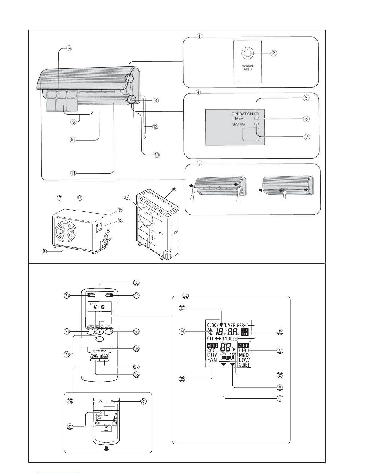
Fig. 1
Fig. 5
Fig. 2
Fig. 3
Fig. 4
Fig. 6
Fig. 8
Fig. 7
Page 5
NAME OF PARTS
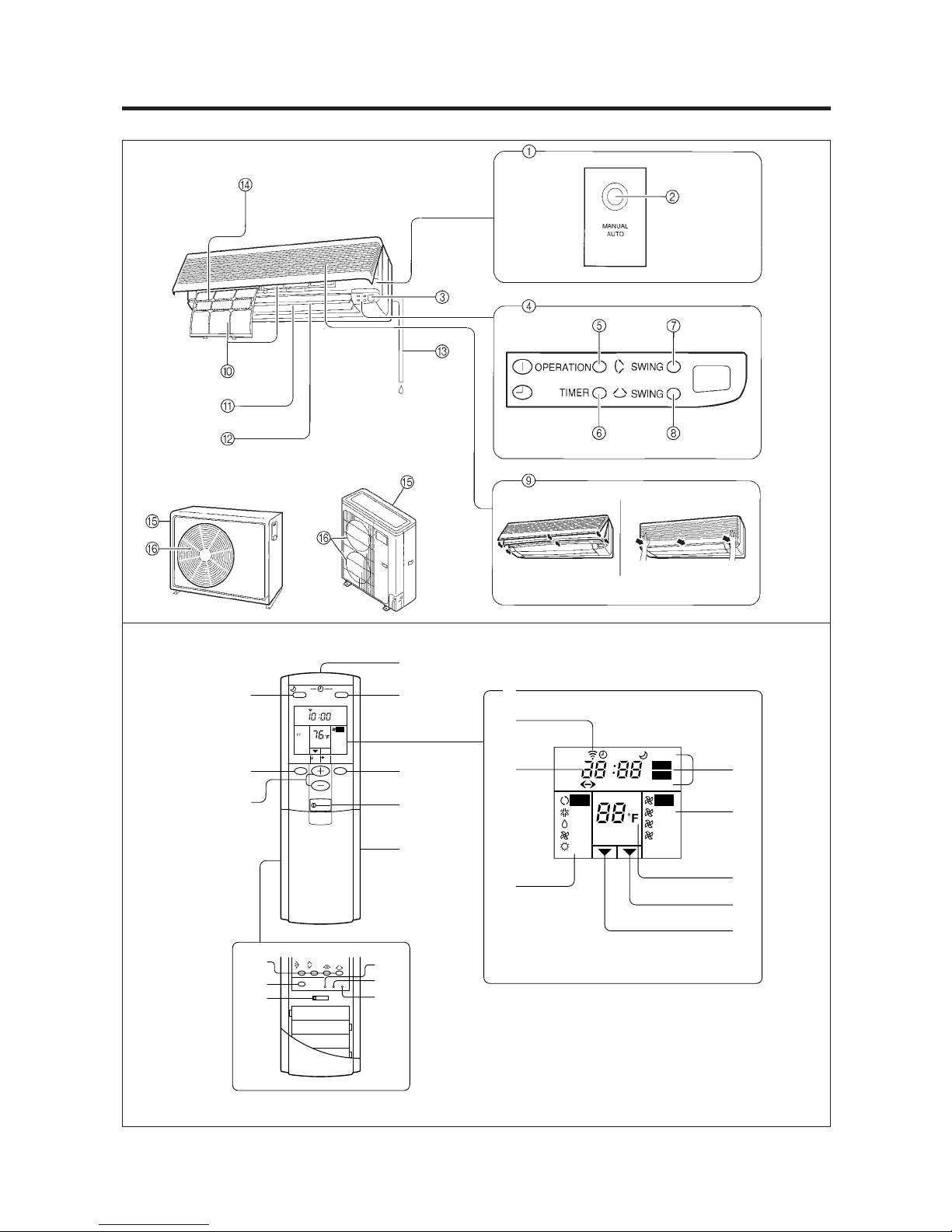
Fig. 1 Indoor Unit
1 Operating Control Panel (Fig. 2)
2 MANUAL AUTO button
3 Remote Control Signal Receiver
4 Indicator Lamps (Fig. 3)
5 OPERATION Indicator Lamp (red)
6 TIMER Indicator Lamp (green)
● If the TIMER indicator lamp flashes when
the timer is operating, it indicates that a
fault has occurred with the timer setting
(see page 17 Auto Restart).
7 SWING Indicator Lamp (orange)
8 Intake Grille (Fig. 4)
9 Air Filter
0 Air Flow Direction Louver
A Right-Left Louvers
(behind Air Flow Direction Louver)
B Drain Hose
C Inter Unit-Line
D Air Cleaning Filter (optional)
Fig. 5 Outdoor Unit
E Power Supply
F Intake Port
G Outlet Port
H Pipe Unit
I Drain port (bottom)
Fig. 6 Remote Control Unit
J SLEEP button
K MASTER CONTROL button
L SET TEMP./SET TIME button (
M Signal Transmitter
N TIMER button
O FAN CONTROL button
P START/STOP button
Q AIR FLOW DIRECTION button
R SWING LOUVER button
Rear side (Fig. 7)
S TIME ADJUST button
T ACL button
(located inside battery compartment)
U TEST RUN button
● This button is used when installing the
unit, and should not be used under normal conditions, as it will cause the air conditioner’s thermostat function to operate
incorrectly.
● If this button is pressed during normal operation, the unit will switch to test operation mode, and the Indoor Unit’s OPERATION Indicator Lamp and TIMER Indicator
Lamp will begin to flash simultaneously.
● To stop the test operation mode, press the
START/STOP button to stop the air conditioner.
V Remote Control Unit Display (Fig. 8)
W Transmit Indicator
X Clock Display
Y Operating Mode Display
Z Timer Mode Display
[ Fan Speed Display
\ Temperature Set Display
] Timer Set Indicator
` Temperature Set Indicator
)
En-4
Page 6
NAME OF PARTS
Instructions relating to heating(*) are applicable only to “HEAT & COOL MODEL” (Reverse Cycle).
Fig. 1
Fig. 2
Fig. 3
Fig. 5
Fig. 6
G
H
I
O
P
Q
MASTER
CONTROL
SLEEP
CLOCK
COOL
SET
ENERGY
SAVE
SET
TEMP
SWING
.
START
STOP
SET
TIME
TIME
ADJUST
Fig. 4
J
TIMER
AUTO
CONTROL
K
FAN
L
M
N
U
V
W
X
*
CLOCK
AM
PM
OFF
A
AUTO
COOL
DRY
FAN
HEAT
TIMER
SLEEP
HM
ON
ENERGY SAVE
ON
OFF
TIMER RESET
AUTO
HIGH
MED
LOW
Y
Z
[
\
]
SET
SWING
TEST
RUN ACL
R
S
Fig. 8
T
Fig. 7
En-5
Page 7
Fig. 1 Indoor Unit
1 Operating Control Panel (Fig. 2)
2 MANUAL AUTO button
3 Remote Control Signal Receiver
4 Indicator Lights (Fig. 3)
5 OPERATION Indicator Light (red)
6 TIMER Indicator Light (green)
7 SWING Indicator Light (orange)
(VERTICAL SWING)
8 SWING Indicator Light (orange)
(HORIZONTAL SWING)
If the TIMER indicator light flashes when
●
the timer is operating, it indicates that a
fault has occurred with the timer setting
(See page 15 Auto Restart).
9 Intake Grille (Fig. 4)
0 Air Filter
A UP/DOWN Air Direction Flaps
B RIGHT/LEFT Air Direction Louvers
(behind UP/DOWN Air Direction Flaps)
C Drain Hose
D Air Cleaning Filter (optional)
Fig. 5 Outdoor Unit
E Intake Side
F Outlet Side
Fig. 6 Remote Control Unit
G SLEEP Button
H MASTER CONTROL Button
I SET TEMP./SET TIME Buttons (
)
J Signal Transmitter
K TIMER Button
L FAN CONTROL Button
M START/STOP Button
N Battery compartment lid
Inside of the battery compartment lid (Fig. 7)
O AIR FLOW DIRECTION Button
P ENERGY SAVE Button
Q CODE CHANGE (Slide Switch)
Switching the remote control unit code.
(Max. 4 units)
R TIME ADJUST Button
S TEST RUN Button
● This button is used when installing the air
conditioner and should not be used under
normal conditions as it will cause the air
conditioner’s thermostat function to operate incorrectly.
● If this button is pressed during normal operation, the unit will switch to test operation mode, and the indoor unit’s OPERATION indicator light and TIMER indicator
light will begin to flash simultaneously.
● To stop the test operation mode, either
press the TEST RUN button once again, or
press the START/STOP button to stop the
air conditioner.
T ACL Button
U Remote Control Unit Display (Fig. 8)
V Transmit Indicator
W Clock Display
X Operating Mode Display
Y Timer Mode Display
Z Fan Speed Display
[ Temperature Set Display
\ Timer Set Indicator
] Temperature Set Indicator
En-6
Page 8
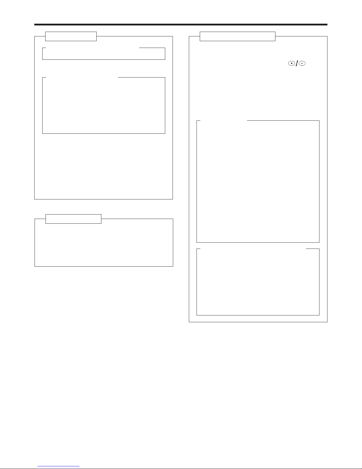
PREPARATION
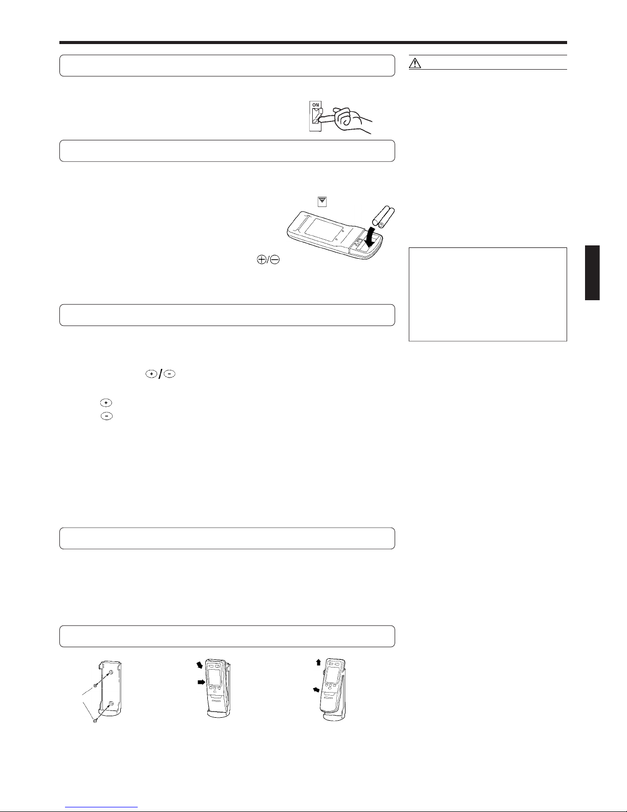
Turn on the Power
In the case of a direct line connection, turn on the circuit
breaker.
Load Batteries (AAA × 2)
Press and slide the battery compartment lid on the re-
1
verse side to open it.
Slide in the direction of the arrow while pressing the mark.
Insert batteries.
2
Be sure to align the battery polarities ( ) correctly.
Close the battery compartment lid.
3
Set the Current time
Press the TIME ADJUST button (Fig. 7 S).
1
Use the tip of a ball-point pen or other small object to press the button.
CAUTION!
● Take care to prevent infants from accidentally swallowing batteries.
● When not using the remote control unit
for an extended period, remove the batteries to avoid possible leakage and damage to the unit.
● If leaking battery fluid comes in contact
with your skin, eyes, or mouth, immediately wash with copious amounts of water, and consult your physician.
● Dead batteries should be removed quickly
and disposed of properly, either by placing in a public battery collection receptacle, or by returning to appropriate authority.
● Do not attempt to recharge dry batteries.
Never mix new and used batteries, or
batteries of different types.
Batteries should last about one year
under normal use. If the remote control
unit’s operating range becomes appreciably reduced, replace the batteries and
press the ACL button (Fig. 7 T) with
the tip of a ballpoint pen or other small
object.
Use the SET TEMP./SET TIME buttons (Fig. 6 L)
2
to adjust the clock to the current time.
button: Press to advance the time.
button: Press to reverse the time.
(Each time the buttons are pressed, the time will be advanced/reversed in
one-minute increments; hold the buttons depressed to change the time
quickly in ten-minute steps.)
Press the TIME ADJUST button again.
3
This completes the time setting and starts the clock.
To Use the Remote Control Unit
● The remote control unit must be pointed at signal receiver (Fig. 1 3) to operate
correctly.
● Operating range: About 7 meters.
● When a signal is properly received by the air conditioner, a beep be heard.
● If no beep is heard, press the remote control unit button again.
Remote Control Unit Holder
Insert
Press in
Screws
Slide up
Pull out
1 Mount the Holder. 2 Set the Remote Control
Unit.
3 To remove the Remote
Control Unit .
En-7
Page 9

PREPARATION
××
Load Batteries (R03/LR03/AAA
× 4)
××
Open the battery compartment lid.
1
1 Slide the battery compartment lid until it stops.
2 While strongly gripping the portion on each side of the battery com-
partment lid that has a rough surface, slide the lid until it comes completely off.
1
Insert batteries.
2
Be sure to align the battery polarities ( ) correctly.
2
Close the battery compartment lid.
3
Set the Current time
Press the TIME ADJUST button.
1
Use the tip of a ball-point pen or other small object to press the button.
Use the ( )SET TIME buttons to adjust the clock to
2
the current time.
button: Press to advance the time.
button: Press to reverse the time.
(Each time the buttons are pressed, the time will be advanced/reversed in
one-minute increments; hold the buttons depressed to change the time
quickly in ten-minute increments.)
2
2
CAUTION!
● Take care to prevent infants from
accidentally swallowing batteries.
● When not using the remote control unit
for an extended period, remove the
batteries to avoid possible leakage and
damage to the unit.
● If leaking battery fluid comes in contact
with your skin, eyes, or mouth, immediately wash with copious amounts of
water, and consult your physician.
● Dead batteries should be removed
immediately and disposed of properly,
either in a battery collection receptacle
or to the appropriate authority.
● Do not attempt to recharge dry batteries.
Never mix new and used batteries, or
batteries of different types.
Batteries should last about one year
under normal use. If the remote control
unit’s operating range becomes appreciably reduced, replace the batteries and
press the ACL button with the tip of a
ballpoint pen or other small object.
SET
SWING
TIME
ADJUST
SWING
TEST
RUN ACL
SET
ENERGY
SAVE
Press the TIME ADJUST button again.
3
This completes the time setting and starts the clock.
To Use the Remote Control Unit
● The remote control unit must be pointed at signal receiver to operate correctly.
● Maximum operating range: Approximately 10 meters. (This may not apply when
the battery is low or there are obstacles.)
● When a signal is properly received by the air conditioner, a beep will be heard.
● If no beep is heard, press the remote control unit button again.
Remote Control Unit Holder
For Hand-Held use
Screws
1 Mount the Holder.
Insert
2 Set the Remote
Control Unit.
Slide up
3 To remove the
Remote Control
Unit.
For Wall Mount use
Screws
1 Mount the Holder.
Insert
2 Set the Remote
Control Unit.
Slide
Screw
3 Attach the unit to
the holder as
shown.
En-8
Page 10

OPERATION
To Select Mode Operation
Press the START/STOP button (Fig.6 P).
1
The indoor unit’s OPERATION indicator lamp (red) (Fig. 3 5) will light.
The air conditioner will start operation.
Press the MASTER CONTROL button (Fig.6 K) to se-
2
lect the desired mode.
Each time the button is pressed, the mode will change in the following
order:
About three seconds later, the entire display will reappear.
ss
AUTO COOL DRY FAN
s
s
To Set the Thermostat
Press the SET TEMP. buttons (Fig. 6 L).
button: Press to raise the thermostat setting.
button: Press to lower the thermostat setting.
● Thermostat setting range:
Cooling/Drying........................ 64 to 88 °F
Fan ........................................... 62 to 88 °F
About three seconds later, the entire display will reappear.
NOTE:
● During Fan mode, set the unit to “– – “ for continuous fan operation regardless of room temperature.
The thermostat setting should be considered a standard value, and may differ
somewhat from the actual room temperature.
To Set the Fan Speed
Press the FAN CONTROL button (Fig. 6 O).
Each time the button is pressed, the fan speed changes in the following order:
s
AUTO HIGH MED LOW QUIET
About three seconds later, the entire display will reappear.
sss
s
Example: When set to COOL
Example: When set to 80 °F
When set to AUTO:
Cooling : As the room temperature approaches that of the thermostat setting,
the fan speed becomes slower.
Fan : The fan will operate at the optimum speed in accordance with the
room temperature in the vicinity of the indoor unit.
When set to QUIET:
SUPER QUIET operation begins. The indoor unit’s airflow will be reduced for
quieter operation.
● SUPER QUIET operation cannot be used during Dry mode. (The same is true
when dry mode is selected during AUTO mode operation.)
● During SUPER QUIET operation, Cooling performance will be reduced somewhat.
En-9
Example: When set to AUTO
In order to increase the drying effect
during quiet cooling operation, the fan of
the indoor unit may stop.
Page 11

To Select Automatic Operation
Press the MASTER CONTROL button to select AUTO.
The operating mode “AUTO” will appear alone in the display. The transmit indicator will flash to indicate the command has been sent, and about three seconds later the entire display panel will reappear.
To Set the Thermostat
Press the TEMPERATURE set button.
LOW HIGH
When set to
4 °F lower
LOW HIGH
When set to
2 °F lower
LOW HIGH
When set to
“normal”
LOW HIGH
When set to
2 °F higher
LOW HIGH
When set to
4 °F higher
About three seconds later, the entire display will reappear.
NOTE: The thermostat setting should be considered a standard value, and may
differ somewhat from the actual room temperature.
To Stop Operation
Press the START/STOP button.
The OPERATION indicator lamp (red) (Fig. 3 5) will go out.
About Mode Operation
AUTO:
● Depending on the room temperature at the time operation begins, the operating
mode will be switched automatically as shown in the accompanying table.
Also, depending on the operating mode, the room temperature setting will cause
the “standard” temperature to be set as shown.
Actual Room Operating Mode Thermostat Setting
Temperature (standard setting)
88 °F or above → Cooling → 82 °F
82 to 88 °F → Cooling → 80 °F
78 to 82 °F → Dry → 76 °F
74 to 78 °F → Dry → 72 °F
Below 74 °F → Dry → 68 °F
Example: When set to “normal”
The operating mode and standard thermostat settings are selected automatically
when operation begins.
● When automatic operation is initiated, the fan will run at very low speed for about
one minute while the unit detects and selects the proper operating mode.
● Once the operating mode has been set, the mode will not change even if the
room temperature changes.
● If the START/STOP button is pressed to recommence operation within two hours
after stopping automatic operation, the unit will begin operating from the same
mode as before.
Cooling:
● Use to cool your room.
Dry:
● Use for gently cooling while dehumidifying your room.
● You cannot heat the room during Dry mode.
● During Dry mode, the unit will operate at low speed; in order to adjust room
humidity, the indoor unit’s fan may stop from time to time. Also, the fan may
operate at very low speed when detecting room humidity.
● The fan speed cannot be changed manually when Dry mode has been selected.
Fan:
● Use to circulate warm air from ceiling area throughout room when using space
heaters.
During Cooling/Dry mode:
Set the thermostat to a temperature setting
that is lower than the current room temperature. The Cooling and Dry modes will not
operate if the thermostat is set higher than
the actual room temperature (in Cooling
mode, the fan alone will operate).
During Fan mode:
● Fan operation begins when room temperature in the vicinity of the air conditioner rises above the set thermostat
temperature; when the temperature
drops, fan operation stops.
● If the air emitted feels too cool, raise
the thermostat setting.
En-10
Page 12

OPERATION
Instructions relating to heating (*) are applicable only to “HEAT & COOL MODEL” (Reverse Cycle).
To Select Mode Operation
Press the START/STOP button.
1
The indoor unit’s OPERATION indicator light (red) will be on.
The air conditioner will start operating.
Press the MASTER CONTROL button to select the de-
2
sired mode.
Each time the button is pressed, the mode will change in the following
order.
AUTO COOL DRY
s
*HEAT FAN
s
t
s
t
About three seconds later, the entire display will reappear.
To Set the Thermostat
Press the SET TEMP. buttons.
button: Press to raise the thermostat setting.
button: Press to lower the thermostat setting.
●Thermostat setting range:
AUTO .................................. 64 to 88 °F
* Heating ............................... 60 to 88 °F
The thermostat cannot be used to set room temperature during the FAN mode (the
temperature will not appear on the remote control unit’s display).
About three seconds later, the entire display will reappear.
The thermostat setting should be considered a standard value, and may differ
somewhat from the actual room temperature.
Cooling/Dry ........................ 64 to 88 °F
SLEEP
MASTER
CONTROL
COOL
SET
TEMP
SET
TIME
.
START
STOP
TIMER
FAN
CONTROL
Example: When set to COOL
SLEEP
MASTER
CONTROL
SET
TEMP
SET
TIME
.
START
STOP
TIMER
FAN
CONTROL
Example: When set to 82 °F
To Set the Fan Speed
Press the FAN CONTROL button.
Each time the button is pressed, the fan speed changes in the following order:
AUTO HIGH MED LOW
ss s s
About three seconds later, the entire display will reappear.
When set to AUTO:
* Heating : Fan operates so as to optimally circulate warm air.
However, the fan will operate at very low speed when the temperature
of the air from the indoor unit is low.
Cooling : As the room temperature approaches that of the thermostat setting,
the fan speed becomes slower.
Fan : The fan alternately turns on and off; when on, the fan runs at the low
fan speed.
The fan will operate at a very low setting during Monitor operation
and at the start of the Heating mode.
To Stop Operation
Press the START/STOP button.
The OPERATION indicator light (red) will turn off.
SLEEP
MASTER
CONTROL
SET
TEMP
SET
TIME
.
START
STOP
TIMER
AUTO
FAN
CONTROL
Example: When set to AUTO
En-11
Page 13

OPERATION
Instructions relating to heating (*) are applicable only to “HEAT & COOL MODEL” (Reverse Cycle).
About Mode Operation
AUTO:
COOLING MODEL
● When the room temperature is 4 ° F
higher than the set temperature, the
mode will switch between Cooling and
Drying.
● During the Drying mode operation, the
FAN setting should be switched to LOW
for a gently cooling effect during which
the fan may temporarily stop rotating.
● If the mode automatically selected by the
unit is not satisfactory, see page 6 for instructions on changing the mode setting
(COOL, DRY, FAN).
AUTO (* AUTO CHANGEOVER):
HEAT & COOL MODEL (Reverse cycle)
● When AUTO CHANGEOVER is selected, the air conditioner selects the appropriate operation mode (Cooling or Heating) according to your room’s present temperature.
● When AUTO CHANGEOVER is first selected, the fan will operate at very low speed
for about one minute while the unit determines the current conditions of the
room and accordingly selects the proper operation mode.
● When the air conditioner has adjusted your room’s temperature to near the thermostat setting, it will begin monitor operation. In the monitor operation mode,
the fan will operate at low speed. If the room temperature subsequently changes,
the air conditioner will once again select the appropriate operation (Heating, Cooling) to adjust the temperature to the value set in the thermostat. (The monitor
operation range is ±4 °F relative to the thermostat setting.)
● If the mode automatically selected by the unit is not satisfactory, see page 6 for
instructions on changing the mode setting (HEAT, COOL, DRY, FAN).
Cooling Operation
Dry Operation
Thermostat control
4 °F
Setting temperature
*Heating:
● Use to warm your room.
● When Heating mode is selected, the air conditioner will operate at very low fan
speed for about 3 to 5 minutes, after which it will switch to the selected fan setting. This period of time is provided to allow the indoor unit to warm up before
begin full operation.
● When the room temperature is very low, frost may form on the outside unit, and
its performance may be reduced. In order to remove such frost, the unit will
automatically enter the defrost cycle from time to time. During Automatic Defrosting operation, the OPERATION indicator light (red) will flash, and the heat
operation will be interrupted.
Cooling:
● Use to cool your room.
Dry:
● Use for gently cooling while dehumidifying your room.
● You cannot heat the room during Dry mode.
● During Dry mode, the unit will operate at low speed; in order to adjust room
humidity, the indoor unit’s fan may stop from time to time. Also, the fan may
operate at very low speed when detecting room humidity.
● The fan speed cannot be changed manually when Dry mode has been selected.
Fan:
● Use to circulate the air throughout your room.
* During Heating mode:
Set the thermostat to a temperature setting that is higher than the current room
temperature. The Heating mode will not
operate if the thermostat is set lower than
the actual room temperature.
During Cooling/Dry mode:
Set the thermostat to a temperature setting that is lower than the current room
temperature. The Cooling and Dry modes
will not operate if the thermostat is set
higher than the actual room temperature
(in Cooling mode, the fan alone will operate).
During Fan mode:
The heat and cool functions of this unit
cannot operate in the Fan mode.
En-12
Page 14

TIMER OPERATION
SLEEP
TIMER
SET
TIME
SET
TEMP
MASTER
CONTROL
FAN
CONTROL
.
TIMER
ON
SLEEP
TIMER
SET
TIME
SET
TEMP
MASTER
CONTROL
FAN
CONTROL
.
TIMER
ON
Instructions relating to heating (*) are applicable only to “HEAT & COOL MODEL” (Reverse Cycle).
Before using the timer function, be sure that the remote control unit is set to the current time (See page 5).
To Use the ON timer or OFF timer
Press the START/STOP button
1
(if the unit is already operating, proceed to step 2).
The indoor unit’s OPERATION indicator light (red) will turn on.
Press the TIMER button to select the OFF timer or ON
2
timer operation.
Each time the button is pressed the timer function changes in the following order:
RESET OFF ON
sss
PROGRAM(OFF → ON, OFF ← ON)
t
The indoor unit’s TIMER indicator light (green) will turn on.
Use the SET TIME buttons to adjust the desired OFF
3
time or ON time.
Set the time while the time display is flashing (the flashing will continue
for about five seconds).
button: Press to advance the time.
button: Press to reverse the time.
About five seconds later, the entire display will reappear.
To Cancel the Timer
Use the TIMER button to select “TIMER
RESET.”
The air conditioner will return to normal
operation.
To Change the Timer Settings
Perform steps 2 and 3.
To Stop Air Conditioner Operation
while the Timer is Operating
Press the START/STOP button.
To Change Operating Conditions
If you wish to change the operating
conditions (Mode, Fan Speed, Thermostat
Setting), after making the timer setting,
wait until the entire display reappears, then
press the appropriate buttons to change to
the desired operating condition.
To Use the PROGRAM timer
Press the START/STOP button
1
(if the unit is already operating, proceed to step 2).
The indoor unit’s OPERATION indicator light (red) will turn on.
Set the desired times for OFF timer and ON timer.
2
See the section “To Use the ON timer or OFF timer” to set the desired
mode and times.
About three seconds later, the entire display will reappear.
The indoor unit’s TIMER indicator light (green) will turn on.
Press the TIMER button to select the PROGRAM timer
3
operation (either OFF → ON or OFF ← ON will display).
The display will alternately show “OFF timer” and “ON timer”, then change
to show the time setting for the operation to occur first.
● The PROGRAM timer will begin operation. (If the ON timer has been
selected to operate first, the unit will stop operating at this point.)
About five seconds later, the entire display will reappear.
To Cancel the Timer
Use the TIMER button to select “TIMER
RESET.”
The air conditioner will return to normal
operation.
To Change the Timer Settings
Follow the instructions given in the section
1.
“To Use the ON Timer or OFF Timer” to select the timer setting you wish to change.
2. Press the TIMER button to select either
OFF → ON or OFF ← ON.
To Stop Air Conditioner Operation
while the Timer is Operating
Press the START/STOP button.
To Change Operating Conditions
If you wish to change the operating
conditions (Mode, Fan Speed, Thermostat
Setting), after making the timer setting,
wait until the entire display reappears, then
press the appropriate buttons to change to
the desired operating condition.
En-13
Page 15

TIMER OPERATION
About the PROGRAM timer
● The PROGRAM timer allows you to integrate OFF timer
and ON timer operations in a single sequence. The sequence can involve one transition from OFF timer to ON
timer, or from ON timer to OFF timer, within a twentyfour hour period.
● The first timer function to operate will be the one set nearest to the current time. The order of operation is indicated by the arrow in the remote control unit’s display
(OFF → ON, or OFF ← ON).
● One example of PROGRAM timer use might be to have
the air conditioner automatically stop (OFF timer) after
you go to sleep, then start (ON timer) automatically in
the morning before you rise.
About the ON timer
● The timer function is designed to bring your room to a
comfortable temperature by the set time; as a result, the
unit automatically begins operation before the set time
so that the room reaches the desired temperature by the
time set on the timer.
● The hotter it is in summer, or the colder it is in winter, the
earlier that operation will begin.
* During Heating Operation ....... from 45 to 10 minutes be-
fore set time.
During Cooling/Dry Operation ... from 20 to 10 minutes be-
fore set time.
During Fan Operation .............. at the set time.
SLEEP TIMER OPERATION
Instructions relating to heating (*) are applicable only to “HEAT & COOL MODEL” (Reverse Cycle).
Unlike other timer functions, the SLEEP timer is designed to set the duration of time in which the unit does not operate.
To Use the SLEEP timer
While the air conditioner is operating or stopped, press the
SLEEP button.
Both the indoor unit’s OPERATION indicator light (red) and the TIMER indicator
light (green) will turn on.
SLEEP
COOL
TIMER
SLEEP
To Change the Timer Settings
MASTER
CONTROL
TEMP
FAN
SET
SET
CONTROL
TIME
.
Press the SLEEP button once again and set the time using the
SET TIME buttons.
Set the time while the Timer Mode Display is flashing (the flashing will continue for
about five seconds).
button: Press to advance the time.
button: Press to reverse the time.
About five seconds later, the entire display will reappear.
About the SLEEP timer
To prevent excessive warming or cooling during sleep, the SLEEP timer function automatically modifies the thermostat setting
in accordance with the time setting. When the set time has elapsed, the air conditioner completely stops.
During Cooling/Dry operation:
When the SLEEP timer is set, the thermostat setting is automatically raised 2 °F every sixty minutes. When the thermostat has been raised a total of 4 °F, the thermostat setting at
that time is maintained until the set time has elapsed, at which
time the air conditioner automatically turns off.
SLEEP timer setting
To Cancel the Timer:
Use the TIMER button to select “TIMER
RESET”.
The air conditioner will return to normal
operation.
To Stop the Air Conditioner During
Timer Operation:
Press the START/STOP button.
Set time
En-14
1 hour
2 °F
4 °F
Page 16
ADJUSTING THE DIRECTION OF AIR CIRCULATION
Instructions relating to heating (*) are applicable only to “HEAT & COOL MODEL” (Reverse Cycle).
Vertical (up-down) direction of airflow is adjusted by pressing the remote control unit’s AIR FLOW DIRECTION VERTICAL SET
button. Horizontal (right-left) direction of airflow is adjusted by pressing the remote control unit’s AIR FLOW DIRECTION
HORIZONTAL SET button.
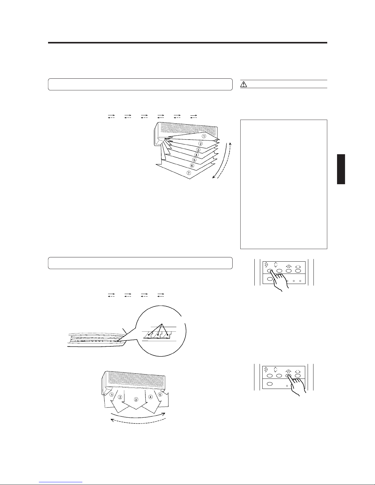
Vertical Air Direction Adjustment
Press the AIR FLOW DIRECTION VERTICAL SET button.
Each time the button is pressed, the air direction range will change as follows:
1
2
3
4
5
6
7
Types of Air flow Direction Setting:
1,2,3,4 : During Cooling/Dry Modes
5,6,7 : * During Heating mode
The remote control unit’s display does
not change.
Fig. 9
● Use the air direction adjustments within the ranges shown above.
● The vertical airflow direction is set automatically as shown, in accordance with
the type of operation selected.
During Cooling/Dry mode : Horizontal flow 1
* During Heating mode : Downward flow 7
● During AUTO mode operation, for the first minute after beginning operation,
airflow will be horizontal 1; the air direction cannot be adjusted during this period.
DANGER!
Never place fingers or foreign objects inside
the outlet ports, since the internal fan operates at high speed and could cause personal
injury.
● Always use the remote control unit’s
AIR FLOW DIRECTION button to adjust
the UP/DOWN air direction flaps or
RIGHT/LEFT air direction louvers. Attempting to move them manually
could result in improper operation; in
this case, stop operation and restart.
The louvers should begin to operate
properly again.
● During use of the Cooling and Dry
modes, do not set the UP/DOWN air
direction flaps in the Heating range (5
to 7) for long periods of time, since
water vapor may condense near the
outlet louvers and drops of water may
drip from the air conditioner.
● When used in a room with infants, children, elderly or sick persons, the air
direction and room temperature
should be considered carefully when
adjusting settings.
Horizontal Air Direction Adjustment
Press the AIR FLOW DIRECTION HORIZONTAL SET button.
Each time the button is pressed, the air direction range will change as follows:
1
2
3
4
5
The remote control unit’s display does
not change.
RIGHT/LEFT air direction louvers
● Use the air direction adjustments within the ranges shown above.
Fig. 10
SET
SWING
TIME
ADJUST
SWING
TEST
RUN ACL
SET
ENAGY
SAVE
Example: When set to vertical air direc-
tion
SET
SWING
TIME
ADJUST
SWING
TEST
RUN ACL
SET
ENERGY
SAVE
Example: When set to horizontal air
direction
En-15
Page 17

ADJUSTING THE DIRECTION OF AIR CIRCULATION
Vertical (up-down) direction of airflow is adjusted by pressing the Remote Control Unit’s AIR FLOW DIRECTION button. Horizontal (right-left) airflow direction is adjusted manually, by moving the Air Flow Direction Louvers.
Whenever making horizontal airflow adjustments, start air conditioner operation and be sure that the vertical air direction
louvers are stopped.
Vertical Air Direction Adjustment
Press the AIR FLOW DIRECTION button (Fig. 6 Q).
Each time the button is pressed, the air direction range will change as follows:
Cooling/Dry
mode
Fan mode
1 2 3 (6)
1 2 3 4 5 6 7
NOTE
● Use the air direction adjustments within the ranges shown above.
● The vertical airflow direction is set automatically as shown, in accordance with
the type of operation selected.
During Cooling/Dry modes : Horizontal flow 1
During Fan mode : Downward flow 6
● If you wish to select a different airflow direction, you may use the remote control
unit’s AIR FLOW DIRECTION button to choose a different setting.
● During AUTO mode operation, for the first minute after beginning operation,
airflow will be horizontal 1; the air direction cannot be adjusted during this period.
NOTE
You can select the air direction 1, 2, 3, or 6 (downward) by pressing the AIR
FLOW DIRECTION button.
Use the air direction 6 when you want to cool yourself for a while after taking
a bath or shower, or after coming back home in summer months.
But, for prevention of condensation on the louver, the air direction 6 is automatically released after 30 minutes and turned to the air direction 3.
Right-Left Adjustment
Adjust the Right-Left louvers.
● Move the Right-Left louvers to adjust air flow in the direction you prefer.
Right-Left Louvers
CAUTION!
Never place fingers or foreign objects inside
the outlet ports, since the internal fan operates at high speed and could cause personal
injury.
● Always use the remote control unit’s
AIR FLOW DIRECTION button to adjust
the vertical airflow louvers. Attempting to move them manually could result in improper operation; in this case,
stop operation and restart. The louvers
should begin to operate properly
again.
● When used in a room with infants, children, elderly or sick persons, the air
direction and room temperature
should be considered carefully when
making settings.
● Always operate the Air Flow Direction
Louvers and the Power Diffuser with
the air flow direction buttons on the
remote control. Forcible movement by
hand can cause incorrect operation. In
such a case, stop the operation to let
the unit return to normal condition.
En-16
knob
Page 18

SWING OPERATION
Begin air conditioner operation before performing this procedure.
To select SWING Operation
Press the SWING LOUVER button (Fig. 6 R).
The SWING indicator lamp (orange) (Fig. 3 7) will light.
In this mode, the Air Flow Direction Louvers will swing automatically to direct
the airflow both up and down.
To Stop SWING Operation
Press the SWING LOUVER button (Fig. 6 R) once again.
The SWING indicator lamp (orange) (Fig. 3 7) will go out.
Airflow direction will return to the setting before swing was begun.
About Swing Operation
● The SWING range is as follows:
Cooling/Dry
mode
Fan mode
● The SWING operation may stop temporarily when the air
conditioner’s fan is not operating or when operating at
very low speeds.
● The airflow direction can not be adjusted during SWING
operation even when the AIR FLOW DIRECTION button is
pressed.
1 3, (4 7)
1 3, 4 7
NOTE
MANUAL AUTO OPERATION
NOTE
The air swings between 4 and 7 by pressing the SWING
LOUVER button after selecting the air direction 6 (downward) by pressing the AIR FLOW DIRECTION button.
Use this operation when you want to cool yourself for a
while after taking a bath or shower, or after coming back
home in summer months.
But, for prevention of condensation on the louver, the
swing of the air direction 4 ↔ 7 is automatically released
after 30 minutes and turned to the swing of the air direction 1 ↔ 3.
Use the MANUAL AUTO operation in the event the Remote Control Unit is lost or otherwise unavailable.
How To Use the Main Unit Controls
Press the MANUAL AUTO button (Fig. 2 2) on the main
unit control panel.
To stop operation, press the MANUAL AUTO button once again.
(Controls are located inside the Intake Grille.)
● When the air conditioner is operated
with the controls on the Main unit, it
will operate under the same mode as
the AUTO mode selected on the Remote Control Unit (see page 8).
● The fan speed selected will be
“AUTO” and the thermostat setting
will be standard.
En-17
Page 19

SWING OPERATION
SET
ENERGY
SAVE
TIME
ADJUST
TEST
RUN ACL
SET
SWING
SWING
Begin air conditioner operation before performing this procedure.
To select Vertical airflow SWING Operation
Press the AIR FLOW DIRECTION VERTICAL SWING button .
The SWING indicator light (VERTICAL SWING) (orange) will turn on.
In this mode, the UP/DOWN air direction flaps will swing automatically to direct the
air flow both up and down.
To Stop Vertical airflow SWING Operation
Press the AIR FLOW DIRECTION VERTICAL SWING button
once again.
The SWING indicator light (VERTICAL SWING) will turn off.
Airflow direction will return to the setting before swing was begun.
About Swing Operation
● The range of swing is relative to the currently set airflow
direction.
Air flow direction set
1
2
3
4
5
6
7
Range of swing
1 to 3
1 to 4
2 to 5
3 to 6
4 to 7
5 to 7
1 to 7 (All range)
Air direction range (See page 10, Fig. 9)
● If the swing range is not as desired, use the remote control unit’s AIR FLOW DIRECTION VERTICAL SET button to
change the range of swing.
● The SWING operation may stop temporarily when the air
conditioner’s fan is not operating, or when operating at
very low speeds.
● During use of the Cooling and Dry modes, do not set the
air UP/DOWN direction flaps, in the Heating range (5 to
7) for long periods of time, since water vapor may condense near the outlet louvers and drops of water may
drip from the air conditioner.
SET
SWING
TIME
ADJUST
SWING
TEST
RUN ACL
SET
ENERGY
SAVE
Example: When set to vertical swing
To select Horizontal airflow SWING Operation
Press the AIR FLOW DIRECTION HORIZONTAL SWING button.
The SWING indicator light (HORIZONTAL SWING) (orange) will turn on.
In this mode, the RIGHT/LEFT air direction louvers will swing automatically to direct
the airflow both right and left.
To Stop Horizontal airflow SWING Operation
Press the AIR FLOW DIRECTION HORIZONTAL SWING button
once again.
The SWING indicator light (HORIZONTAL SWING) will turn off.
Airflow direction will return to the setting before swing was begun.
About Swing Operation
● The range of swing is relative to the currently set airflow
direction.
Air flow direction set
1
2
3
4
5
Range of swing
1 to 5 (All range)
1 to 3
2 to 4
3 to 5
1 to 5 (All range)
Air direction range (See page 10, Fig. 10)
● If the swing range is not as desired, use the remote control unit’s AIR FLOW DIRECTION HORIZONTAL SET button to change the range of swing.
● The SWING operation may stop temporarily when the air
conditioner’s fan is not operating, or when operating at
very low speeds.
Example: When set to horizontal swing
En-18
Page 20

ENERGY SAVE OPERATION
Instructions relating to heating (*) are applicable only to “HEAT & COOL MODEL” (Reverse Cycle).
The air conditioner can be operated while keeping energy consumption costs down.
How To Use the ENERGY SAVE OPERATION
Press the START/STOP button
1
(if the unit is already operating, proceed to step 2).
The indoor unit’s OPERATION indicator light (red) will turn on.
Press the MASTER CONTROL button to select the
2
COOL, DRY, *HEAT mode.
To Cancel the ENERGY SAVE:
Press the ENERGY SAVE button.
3
ENERGY SAVE can only be used if the MASTER CONTROL button is used
to select the “COOL”, “DRY” or *“HEAT”.
About the ENERGY SAVE
The air conditioner saves energy costs by controlling the thermostat temperature setting.
During Cooling/Dry operation:
The thermostat temperature setting increases by 2 °F as soon
as the ENERGY SAVE button is pressed, and then increases
by another 2 °F after one hour has passed.
In this manner, energy is saved by continuing to cool or dry
at a thermostat temperature of 4 °F above the setting.
Press the ENERGY SAVE button.
SET
SWING
ENERGY
SAVE
SET
TIME
ADJUST
SWING
TEST
RUN ACL
ENERGY SAVE setting
ENERGY
SAVE ON
1 hour
2 °F
MANUAL AUTO OPERATION
Use the MANUAL AUTO operation in the event the remote control unit is lost or otherwise unavailable.
How To Use the Main Unit Controls
Press the MANUAL AUTO button on the main unit control
panel.
To stop operation, press the MANUAL AUTO button once again.
CAUTION!
Do not press the MANUAL AUTO button with
wet hands or pointed objects, otherwise an
electric shock or malfunction may occur.
● When the air conditioner is operated
with the controls on the Main unit, it
will operate under the same mode as
the AUTO mode selected on the remote control unit (see page 7).
● The fan speed selected will be “AUTO”
and the thermostat setting will be 73 °F.
4 °F
Set temperature
En-19
Page 21

CLEANING AND CARE
CAUTION!
● Before cleaning the air conditioner, be sure to turn it off and disconnect the power supply.
● Be sure the intake grille is installed securely.
● When removing and replacing the air filters, be sure not to touch the heat exchanger, as per-
sonal injury may result.
● Turn off the circuit breaker.
Cleaning the Intake Grille
1. Remove the intake grille.
1 Place your fingers at both lower ends of the grille
panel, and lift forward; if the intake grille seems to
catch partway through its movement, continue lifting
upward to remove.
2 Lift up the intake grille fully to remove.
Intake Grille
2. Clean with water.
Remove dust with a vacuum cleaner; wipe the unit with
warm water, then dry with a clean, soft cloth.
Cleaning the Air Filter
1. Open the intake grille, and remove the air
filter.
Lift up the air filter’s handle, disconnect the two lower
tabs, and pull out.
Air filter handle
Hooks (two places)
2. Remove dust with a vacuum cleaner or by
washing.
After washing, allow to dry thoroughly in a shady place.
3. Replace the air filter and close the intake
grille.
1 Align the sides of the air filter with the panel, and push
in fully, making sure the two lower tabs are returned
properly to their openings in the panel.
3. Replace the intake grille.
1 Holding the intake grille horizontally, fasten the two
upper hooks on the unit.
Intake Grille
2 Press the intake grille down at the lower sides to close.
2 Close the intake grille.
(In the illustration, the unit is shown without the intake grille
installed.)
● Dust can be cleaned from the air filter either with a vacuum
cleaner, or by washing the filter in a solution of mild detergent and warm water. If you wash the filter, be sure to
allow it to dry thoroughly in a shady place before reinstalling.
● If dirt is allowed to accumulate on the air filter, air flow
will be reduced, lowering operating efficiency and increasing noise.
● During periods of normal use, the air filters should be
cleaned every two weeks.
Hooks (two places)
When using the optional Air Cleaning Filter
● Install the optional air cleaning filter set as instructed (installation instructions are furnished with the air cleaning filter set).
● When used for extended periods, the unit may accumulate dirt inside, reducing its performance. We recommend that the
unit be inspected regularly, in addition to your own cleaning and care. For more information, consult authorized service
personnel.
● When cleaning the unit’s body, do not use water hotter than 100 °F, harsh abrasive cleansers, or volatile agents like
benzene or thinner.
● Do not expose the unit body to liquid insecticides or hairsprays.
● When shutting down the unit for one month or more, first allow the fan mode to operate continuously for about one-half
day to allow internal parts to dry thoroughly.
En-20
Page 22

Cleaning the Intake Grille
1. Open the Intake Grille.
1 Place your fingers at both lower ends of the grille
panel, and lift forward; if the grille seems to catch
partway through its movement, continue lifting upward to remove.
2 Pull past the intermediate catch and open the Intake
Grille wide so that it becomes horizontal.
Intake Grille
2. Unlock the Intake Grille.
Hold the Intake Grille with one hand and pull the Knobs
on the right and the left all the way to unlock the Intake
Grille.
Intake Grille
4. Set the mounting shaft of the Intake Grille
into the bearings at the top of the panel.
1 Pull the Knobs all the way.
2 Hold the grille horizontal and set the left and right
mounting shafts into the bearings at the top of the
panel.
Mounting
shaft
Intake
Grille
Bearing
Knob
5. Lock the Intake Grille.
Hold the Intake Grille with one hand and push the Knobs
on the right and the left all the way in to lock the Intake
Grille mounting shafts.
Intake Grille
Mounting shaft
Knob
Raise the horizontal Intake Grille to remove it.
3. Clean with water.
Remove dust with a vacuum cleaner: wipe the unit with
warm water, then dry with a clean, soft cloth.
Mounting shaft
Knob
6. Close the Intake Grille.
Push the lower edge of the Intake Grille at both ends and
at the center to close it.
Intake Grille
CAUTION!
Do not operate with open Intake Grille, as this can
cause accidents.
En-21
Page 23
TROUBLESHOOTING
Instructions relating to heating (*) are applicable only to “HEAT & COOL MODEL” (Reverse Cycle).
WARNING!
Before requesting service, perform the following checks:
In the event of a malfunction (burning smell, etc.), immediately stop operation, turn off the circuit breaker, and consult authorized service personnel.
Merely turning off the unit’s power switch will not completely disconnect the unit from the power
source. Always be sure to turn off your circuit breaker to ensure that power is completely off.
NORMAL
FUNCTION
Symptom
Doesn’t operate immediately:
Noise is heard:
Odor:
Mist or steam are
emitted:
Problem
● If the unit is stopped and then immediately started again, the compressor will not operate for about 3 minutes, in order to prevent
fuse blowouts.
● Whenever the power switch is turned off then on again, the protection circuit will operate for about 3 minutes, preventing unit
operation during that period.
● During operation and immediately after stopping the unit, the
sound of water flowing in the air conditioner’s piping may be
heard. Also, noise may be particularly noticeable for about 2 to 3
minutes after starting operation (sound of coolant flowing).
● During operation, a slight squeaking sound may be heard. This is
the result of minute expansion and contraction of the front cover
due to temperature changes.
*● During Heating operation, a swoosh sound may be heard occa-
sionally. This sound is produced by the Automatic Defrosting operation.
● Occasionally an odor may be emitted from the indoor unit. This
may be the result of room odors (furniture, tobacco, etc.) which
have been taken into the air conditioner.
● During Cooling or Dry operation, a thin mist may be seen emitted
from the indoor unit. This results from the sudden Cooling of
room air by the air emitted from the air conditioner, resulting in
condensation and misting.
See Page
—
—
15
—
—
Airflow is weak or stops:
Water is produced from
the outdoor unit:
*● During Heating operation, the outdoor unit’s fan may stop, and
steam may be seen rising from the unit. This is due to Automatic
Defrosting operation.
*● When Heating operation is started, fan speed is temporarily very
low, to allow internal parts to warm up.
*● During Heating operation, if the room temperature rises above
the thermostat setting, the outdoor unit will stop, and the indoor
unit will operate at very low fan speed. If you wish to warm the
room further, set the thermostat for a higher setting.
*● During Heating operation, the unit will temporarily stop opera-
tion (between 7 and 15 minutes) as the Automatic Defrosting mode
operates. During Automatic Defrosting operation, the OPERATION
indicator light will flash.
● The fan may operate at very low speed during Dry operation or
when the unit is monitoring the room’s temperature.
● In the monitor AUTO operation, the fan will operate at very low
speed.
*● During Heating operation, water may be produced by the out-
door unit due to Automatic Defrosting operation.
15
—
15
6
6
15
En-22
Page 24

TROUBLESHOOTING
Instructions relating to heating (*) are applicable only to “HEAT & COOL MODEL” (Reverse Cycle).
Symptom
CHECK ONCE
MORE
If the problem persists after performing these checks, or if you notice burning smells, or the TIMER indicator light flashes,
immediately stop operation, disconnect the power supply, and consult authorized service personnel.
Doesn’t operate at all:
Poor Cooling
(or *Heating)
performance:
The unit operates
differently from the
remote control unit’s
setting:
● Has there been a power failure?
● Has a fuse blown out, or a circuit breaker been tripped?
● Is the timer operating?
● Is the air filter dirty?
● Is the air conditioner’s intake grille or outlet port blocked?
● Did you adjust the room temperature settings (thermostat) cor-
rectly?
● Is there a window or door open?
● In the case of Cooling operation, is a window allowing bright sun-
light to enter? (Close the curtains.)
● In the case of Cooling operation, are there heating apparatus and
computers inside the room, or are there too many people in the
room?
● Are the remote control unit’s batteries dead?
● Are the remote control unit’s batteries loaded properly?
Items to check
See Page
—
8 to 9
—
5
En-23
Page 25

OPERATING TIPS
Temperature and Humidity Range
Cooling and Dry Mode
Indoor temperature
Outdoor temperature
Indoor humidity
DB : Dry Bulb Temperature
WB : Wet Bulb Temperature
● If the air conditioner is used under higher temperature conditions than those listed, the built-in protection circuit may
operate to prevent internal circuit damage. Also, during Cooling and Dry modes, if the unit is used under conditions of
lower temperature than those listed above, the heat-exchanger may freeze, leading to water leakage and other damage.
● Do not use this unit for any purposes other than the Cooling, Dehumidifying, and air-circulation of rooms in ordinary
dwellings.
Maximum
Minimum
Maximum
Minimum
Outdoor
Temperature
68 °F or above
Outdoor
Temperature
below 68 °F
If the unit is used for long periods under high-humidity conditions, condensation
may form on the surface of the indoor unit, and drip onto the floor or other objects
underneath.
If the unit is used for long periods under high-humidity conditions, condensation
may form on the surface of the indoor unit, and drip onto the floor or other objects
underneath.
95 °F DB / 71 °F WB
64 °F DB / 55 °F WB
115 °F DB
32 °F DB
About 80 % or less
About 50 % or less
En-24
 Loading...