

Page 1

FUTRO S450
Operating Manual
Page 2

Sie haben...
... technische Fragen od
er Probleme?
Wenden Sie sich bitte an:
• unsere Hotline/Help Desk
(siehe die mitgelieferte Help Desk-Liste oder im
Internet: "
http://ts.f
ujitsu.com/he lpdesk")
• Ihren zuständigen Vertriebspartner
• Ihre Verkaufsstelle
Weitere Informationen finden Sie in den Handbüchern "Sicherheit" und "Garantie".
Aktuelle Informationen zu unseren Produkten, Tipps, Updates usw. finden
Sie im Internet: "
http://ts.fujitsu.com"
Are there ...
... any technical problems or other questions you need clarified?
Please contact:
• our Hotline/Help Desk (see the Help Desk list or go to:
"
http://ts.fujitsu.com/helpdesk")
• your sales partner
• your sales outlet
Further information can be found in the "Safety" manual.
The latest information on our products, tips, updates, etc., can be found
on the Internet under: "
http://ts.fujitsu.com"
Page 3

Page 4

Published by
Fujitsu Technology Solutions GmbH
A26361-K522-Z226-1-7419, Edition 2
2009/06
Produced by
XEROX Global Services
Page 5

FUTRO S450
Deutsch
English
Operating Manual
Page 6

FUTRO sind eingetragene Warenzeichen der Fujitsu Technology Solutions GmbH.
Microsoft, MS, MS-DOS, Windows, Windows NT, Windows 2000, Windows XP und Windows
Vista sind eingetragene Warenzeichen der Microsoft Corporation.
VESA und DPMS sind Warenzeichen der Video Electronics Standards Association.
PS/2 ist ein eingetragenes Warenzeichen von International Business Machines, Inc.
Pentium ist ein eingetragenes Warenzeichen der Intel Corporation, USA.
Kensington und MicroSaver sind eingetragene Warenzeichen der ACCO World Corporation.
Alle and eren Warenzeichen sind Warenzeichen oder eingetragene Warenzeichen der
jeweiligen Inhaber und werden als geschützt anerkannt.
Copyright © Fujitsu Technology Solutions GmbH 2 009
Alle Rechte vorbehalten, insbesondere (auch auszugsweise) die der Übersetzung, des
Nachdrucks, der Wiedergabe durch K opieren oder ähnliche Verfahren.
Zuwiderhandlungen verpflichten zu Schadenersatz.
Alle Rechte vorbehalten, insbesondere für den Fall der Patenterteilung oder GM-Eintragung.
Liefermöglichkeiten und technische Änderu ngen vorbehalten.
Page 7

Inhalt
Deutsch
Inhalt
Ihr FUTRO S450... ...................................................................... 1
Darstellungsmittel ....................................................................... 1
WichtigeHinweise ..................................................................... 2
Sicherheitshinweise ..................................................................... 2
Gerät transportieren ..................................................................... 2
Gerät reinigen .......................................................................... 3
Energie sparen, Entsorg
ung undRecycling ................................................
3
FCC Class B Compliance St
atement .....................................................
4
CE-Kennzeichnung . . . .................................................................. 4
Inbetriebnahme ........................................................................ 5
AnschlüsseundBedienelemente ........................................................ 5
Vorderansicht ....................................................................... 5
Rückansicht ........................................................................ 6
Gerät aufstellen ......................................................................... 7
Senkrechte Betriebslage ............................................................. 7
Waagerechte Betriebslage (optional) . . . . . . ............................................ 8
Bildschirm, MausundTastaturanschließen ............................................... 9
Bildschirm anschließen .............................................................. 9
Maus anschließen ................................................................... 10
Tastaturanschließen ................................................................ 10
Gerät an dasNetzwerk (LAN) anschließen ................................................ 10
ExterneGeräteanschließen ............................................................. 11
Leitungen anschließen . . . . ........................................................... 11
Leitungen lösen . . . .................................................................. 11
Anschlüsse amGerät ................................................................ 12
ExterneGerätean die serielleSchnittstelleanschließen ................................ 13
ExterneGerätean die USB-Anschlüsse anschließen ................................... 13
Mikrofon,Kopfhörer und Line-Out-Geräte anschließen .................................. 14
Netzadapter anschließen . ........................................................... 14
Bedienung ............................................................................. 15
Gerät eins
chalten .......................................................................
15
Gerät auss
chalten ......................................................................
15
BIOS-Setu
paufrufen ....................................................................
16
PXE-Syst
emstart ........................................................................
16
Konfigura
tionsmenüdesPXE-Systemstartsaufrufen ...................................
16
Systemerweiterungen .................................................................. 18
Hinweise zu Baugruppen . . . . . ........................................................... 18
Gehäuse öffnen ......................................................................... 19
Gehäuse schließen ..................................................................... 20
SmartCard-Leser einbauen . . . ........................................................... 21
SmartCard-Leser ausbauen . . . ........................................................... 22
Lithium-Batterietauschen ................................................................ 23
Tech
nischeDaten .....................................................................
24
A26361-K522-Z226-1-7419, Ausga be 2 Deutsch
Page 8

Inhalt
Deutsch A26361-K522-Z226-1-7419, Ausgabe 2
Page 9

Ihr FUTRO S450...
Ihr FUTRO S450...
…ist ein universeller Netzwerk-Client. Das intelligente und flexible Terminal ist zuverlässig und leicht
zu warten. Der Thin Client benötigt keine Lüfter und keine Festplatte. Dadurch ist er besonders
leise im Betrieb. Das Betriebssystem ist auf einem Comp act Flash installiert.
Darstellungsmittel
kennzeichnet Hinweise, bei deren Nichtbeachtung Ihre Gesundheit, die
Funktionsfähigkeit Ihres Geräts oder die Sicherheit Ihrer Daten gefährdet
sind. Die G ewährleistung erlischt, wenn Sie durch Nich tbeachtung dieser
Hinweise Defekte am Gerät verursachen
kennzeichnet wichtige In
formationen für den sachgerechten Umgang mit
dem Gerät
kennzeichnet auf dem Gerä t angebrachte Hinweise, deren Nichtbeachtung
Ihre G esundheit gefährdet oder zu Sachschäden führt.
►
kennzeichnet einen Arbeitsschritt, den Sie ausführen müssen
kennzeichnet ein Resultat
Diese Schrift
kennzeichnet Eingaben, die Sie mit der Tastatur in einem Programm-Dialog
oder in einer Kommandozeile vornehmen, z. B. Ihr Passwort (Name123)
oder einen Befehl, um ein Programm zu starten (start.exe)
Diese Schrift
kennzeichnet Informa
tionen, die von einem Programm am Bildschirm
ausgegeben werden, z.
B.: Die Installation ist abgeschlossen!
Diese Schrift
kennzeichnet
• Begriffe und Texte in e
iner Softwareoberfläche, z. B.: Klicken Sie auf
Speichern.
• Namen von Programmen oder Dateien, z. B. Windows oder setup.exe.
"Diese Schrift"
kennzeichnet
• Querverweise auf einen anderen Abschnitt z. B. "Sicherheitshinweise"
• Querverweise auf eine
externe Quelle, z. B. eine Webadresse: Lesen
Sie weiter auf "
http:/
/ts.fujitsu.com"
• Namen von CDs, DVDs sowie Bezeichnungen und Titel von anderen
Materialien, z. B.: "CD/DVD Drivers & Utilities" oder Handbuch
"Sicherheit"
Abc
kennzeichnet eine Taste auf der Tastatu r, z. B:
F10
Diese Schrift kennzeichnet Begriffe und Texte, die beto nt oder hervorgehoben werden,
z. B.: Gerät nicht ausschalten
A26361-K522-Z226-1-7419, Ausgabe 2 Deutsch - 1
Page 10
Wichtige Hinweise
Wichtige Hinweise
WichtigeHinweiseHinweise
In diesem Kapitel finden Sie unter anderem Sicherheitshinweise, die Sie beim
Umgang mit Ihrem Gerät unbedingt beachten müssen.
Sicherheitshinweise
SicherheitshinweiseHinweis
Beachten Sie die Sicherheitshin
weise im Handbuch "Sicherheit" und
die nachfolgenden Sicherheits
hinweise.
Beachten Sie beim Aufstellen und
beim Betrieb des Geräts die Hinweise
für die Umgebungsbedingungen im
Kapitel "
Technische Daten ", Seite 24
und das Kapitel "Inbetriebnahm
e", Seite 5.
Tauschen Sie die Lithium Batteri
e auf dem M ainboard nur entsprechend den
Angaben im Kapitel "
Lithium-B
atterie tauschen", Seite 23.
Die mitgelieferte Netzleitun
g entspricht den Anforderungen des La ndes, in
dem Sie das Gerät gekauft haben
. Achten Sie darauf, dass die Netzleitung
für das Land zugelassen ist, i
n dem sie verwendet wird.
Die Netzleitung des Netzadapt
ers darf nur dann an eine Steckdose
angeschlossen sein,wenn da s
Gerät angeschlossen ist.
Benutzen Sie den Netzadapter n
icht für and ere Geräte.
Benutzen Sie nur den für das Ge
rät vorgesehenen Netzadapter, siehe
Kapitel "
Technische Daten "
, Seite 24.
Versichern Sie sich, dass die
Stromaufnahme des Netzadapters nicht höher ist
als die des Stromnetzes, an d
as Sie den Netzadapter anschließen.
Der Ein-/Ausschalter trennt
das Gerät nicht von der Netzspannung. Zur
vollständigen Trennung von
der N etzspann ung müssen Sie den Netzstecker
aus der geerdeten Schutzkon
takt-Steckdose ziehen.
Gerät transportieren
GerätTransportWiedertransport
Transportieren Sie alle Geräte einzeln und nur in ihrer Originalverpackung oder in einer
anderen geeigneten Verpackung, die Schutz gegen Stoß und Schlag gewährt.
Packen Sie die Geräte erst am Aufstellungsort aus.
2 - Deutsch A26361-K522-Z226-1-7419, Ausgabe 2
Page 11

Wichtige Hinweise
Gerät reinigen
GerätTransportWiedertransportSystemeinheit,sieheGerät
Schalten Sie das Gerät und alle daran angeschlossenen Geräte aus und ziehen
Sie den Netzstecker aus der geerdeten Schutzkontakt-Steckdose.
Der Gehäuseinnenraum des G eräts darf nur von autorisiertem
Fachpersonal g ereinigt werden.
Verwenden Sie für die Reinigung kein Scheuerpulver und keine
Kunststoff lösenden Reinigungsmittel.
Achten Sie darauf, dass keine Flüssigkeit in das Innere der Geräte gelangt.
Die Gehäuseoberfläche können Sie m
it einem trockenen Tuch reinigen. Bei starker
Verschmutzung können Sie ein feuc
htes Tuch b enutzen, das Sie in Wasser mit mildem
Spülmittel getaucht und gut ausge
wrungen haben.
Tastatur und Maus können Sie außen
mit Desinfektionstüchern reinigen.
Energie sparen, Entsorgung u nd Recycling
EntsorgungEnergiesparenRecy clingDVDDrivers&UtilitiesDVDUserDocumentation
Informationen zu diesen Themen finden Sie auf der DVD "Drivers & Utilities".
A26361-K522-Z226-1-7419, Ausgabe 2 Deutsch - 3
Page 12

Wichtige Hinweise
FCC Class B Compliance Statement
The following statement applies to the products covered in this manual, unless otherwise specified
herein. The statement for other products will appear in the accompanying documentation.
NOTE:
This equipment has been tested and found to comply with the limits for a "Class B" digital
device, pursuant to Part 15 of the FCC rules and meets all requirements of the Canadian
Interference-Causing Equipment Standard ICES-003 for digital apparatus. These limits are
designed to provide reasonable protection against harmful interference in a residential installation.
This equipment generates, u ses and can radiate radio freque ncy energy and, if not installed
and used in strict accordance with the instructions, may cause harmful interference to radio
communications. However, there is no guarantee that interference will not occur in a particular
installation. If this equipment does cau se harmful interference to radio or t elevision r ece ption ,
which can be determined by turning the equipment off and on, the user is encouraged to
try to correct the interference by one or more of the following measures:
• Reorient or relocate the receiving antenna.
• Increase the separation between equipment and the receiver.
• Connect the equipment into an outlet on a c ircuit different from that to
which the receiver is connected.
• Consult the dealer or an experienced radio/TV technician for help.
Fujitsu Technology Solutions GmbH is not responsible for any radio or television interference
caused by unauthorized modifications of this equipment or the substitution or attachment
of connecting cables and equipment other than those specified by Fujitsu Technology
Solutions GmbH. The correction of interferences caused by such unau thorized modification,
substitution or attachment will be the responsibility of the user.
The use of shielded I/O cables is required when connecting this equipment to any and all optional
peripheral or host devices. Failure to do so may violate FCC and ICES rules.
CE-Kennzeichnung
Dieses Gerät erfüllt in der ausgelieferten Ausführung die Anforderungen
der EG-Richtlinien 2004/108/EG "Elektromagnetische Verträglichkeit" und
2006/95/EG "Niederspannungsrichtlinie".
4 - Deutsch A26361-K522-Z226-1-7419, Ausgabe 2
Page 13

Inbetriebnahme
Inbetriebnahme
Inbetriebnahme
Beachten Sie die Sicherheitshinweise im Kapitel "Wichtige Hinweise", Seite 2.
Anschlüsse und Bedienelemente
Anschlüsse
In diesem Kapitel werden die einzelnen Hardw are-Komponenten Ihres Geräts vorgestellt. Sie
erhalten eine Übersicht über die Anschlüsse und Bedienelemente des Geräts. Machen Sie
sich m it diesen Elementen vertraut, bevor Sie mit dem Gerät arbeiten.
Vorderansicht
EinschalterAusschalterBetriebsanzeigeSm artCard-LeserFlashspeicherzugr
iff
KopfhöreranschlussAudioausgangMikrofonanschlussUSB
5
4
3
2
6
7
1
1 = SmartCard-Leser
2 = Anzeige für SmartCard-Le
ser
3 = Flashspeicherzugriff
4 = Mikrofonanschluss
5 = USB-Anschlüsse (Universal Serial Bus)
6 = Ein-/Ausschalter
7 = Kopfhöreranschluss, Audioausgang
(Line Out)
A26361-K522-Z226-1-7419, Ausgabe 2 Deutsch - 5
Page 14
Inbetriebnahme
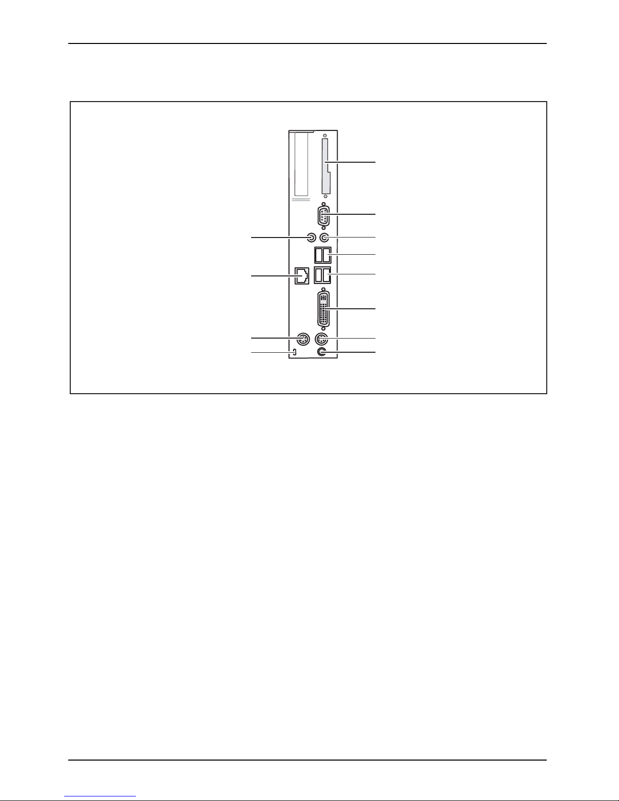
Rückansicht
RJ45-LAN-Ansc hlussPS/2-MausanschlussEinbauplatzPS/2-TastaturanschlussBildschirmanschlussSerielleSchnittstelleUSB-AnschlüsseAudioausgangGleichspannungsbuchseAudioeingangKensingtonLock
1
2
3
4
6
4
5
7
8
9
10
11
1 = Blende
2 = Serielle Schnittstelle
3 = Audioausgang (Line Out)
4 = USB-Anschlüsse (Unive rsal Serial Bus)
5 = DVI-Bildschirmanschlus
s
6 = PS/2-Tastaturanschluss
7 = Gleichspannungsbuchse (DC
IN)
8 = Kensington Lock-Vorrichtung
9 = PS/2-Mausanschluss
10 = RJ45-LAN-Anschluss (Local Area
Network)
11 = Audioeingang (Line In)
6 - Deutsch A26361-K522-Z226-1-7419, Ausgabe 2
Page 15

Inbetriebnahme
Gerät aufstellen
Damit das Gehäuse ausreichend belüftet wird und um Überhitzung zu verm eiden,
darf das Gerät nur mit befestigtem Standfuß betrieben werden.
Montieren Sie die Sta ndfüße für waagerechten oder senkrechten Betrieb (siehe
"
Senkrechte Betriebslage", Se ite 7 und "Waagerechte Betriebslage (optional)", Seite 8).
Standfüße für waagerechten Betrieb sind optional erhältlich.
Senkrechte Betriebslage
SenkrechteBetriebslageBetriebslagesenkrechtAufstellfüßeSeitenteil
Benutzen Sie den mitgelieferten Standfuß, wenn Sie das Gerät in
senkrechter Betriebslage be treiben wollen.
Gehen Sie wie folgt vor, um das Gerät in senkrechter Betriebslage zu betreiben:
► Lösen Sie ge gebenfalls die Leitungen.
► Schieben Sie das Gerät in P feilrichtung auf den Standfuß.
► Stecken Sie gegebe
nenfalls die zuvor gelösten Leitungen wieder.
A26361-K522-Z226-1-7419, Ausga be 2 Deutsch - 7
Page 16

Inbetriebnahme
Waagerechte Betriebslage (optional)
Gehen Sie wie folgt vor, um das Gerät in waagrechter Betriebslage zu betreiben:
WaagrechteBetriebslageBetriebslagewaagrechtAufstellfüße
► Lösen Sie gegebenfalls die Leitungen.
► Legen Sie das Gerät auf einer stabilen, ebenen und sauberen Unterlage auf die Oberseite.
► Positionieren Sie die Standfüße auf der Unterseite des Geräts.
1
1
1
1
► Schrauben Sie die Standfüße mit den Schrauben (1) fest.
► Stecken Sie gegebenenfalls die zuvor gelösten Leitungen wieder.
8 - Deutsch A26361-K522-Z226-1-7419, Ausgabe 2
Page 17

Inbetriebnahme
Bildschirm, Maus und Tastatur anschließen
PS/2-Tastaturanschluss,
violett
USB-Anschluss,
schwarz
(USB-Maus,
USB-Tastatur)
DVI-Bildschirmanschluss,
weiß
PS/2-Mausanschluss,
grün
Bildschirm anschließen
► Bereiten Sie den Bildschirm vor, wie in der Betriebsanleitung zum Bildschirm
beschrieben (z. B. Leitungen stecken).
Bildschirm
► Stecken Sie die Datenleitung in den DVI-Bildschirmanschluss des Geräts.
► Schließen Sie die Netzleitung des Bildschirms a n eine geerdete Schutzkontakt-Steckdose an.
A26361-K522-Z226-1-7419, Ausgabe 2 Deutsch - 9
Page 18

Inbetriebnahme
Maus anschließen
MausAnschließen
USB-Maus anschließen
► Schließen Sie die USB-Maus an einen USB-Anschluss des Geräts an.
USB-AnschlussUSB-Anschluss
PS/2-Maus anschließen
Wenn Sie am PS/2-Mausanschluss keine Maus anschließen, können Sie im BIOS-Setup
den Maus-Controller abschalten und so den IRQ12 für eine andere An wendun g freigeben.
► Schließen Sie die PS/2-Maus an den PS/2-Mausanschluss des Geräts an.
PS/2-MausAnschließenPS/2-Maus
Tastatur anschließen
Tasta turAnschließen
USB-Tastatur anschließen
Verwenden Sie nur die mitgelieferte Tast
aturleitung.
USB-AnschlussAnschließen
► Stecken Sie den rechteckigen Stecker der Tas
taturleitung in die rechteckige Buchse
an der Unterseite oder an der Rückseite der Ta
statur.
► Schließen S ie den flachen rechteckigen USB-Stecker der Tastaturleitung
an einen USB-Anschluss des Geräts.
USB-Anschluss
PS/2-Tastatur anschließen
Verwenden Sie nur die mitgelieferte Tastaturleitung.
PS/2-TastaturanschließenAnschließen
► Stecken Sie den rechteckigen Stecker der Tastaturleitung in die rechteckige Buchse
an der Unterseite oder an der Rückseite der Tastatur.
► Stecken S ie den runden Stecker der Tastaturlei
tung in den PS/2-Tastatu ranschluss des Geräts.
Tasta tur
Gerät an das Netzwerk (LAN) anschließen
LAN
► Schließen Sie die 10/100/1000-Base-T-Netzleitung an den RJ45-LAN-Anschluss an.
10 - Deutsch A26361-K522-Z226-1-7419, Ausgabe 2
Page 19

Inbetriebnahme
Externe Geräte anschließen
Lesen Sie die Dokumentation zum externen Gerät, bevor Sie es anschließen.
Außer bei USB-Geräten müssen die Netzstecker g ezo gen sein, wenn
Sie externe Geräte anschließen!
Bei Gewitter dürfen Sie Leitungen weder stecken noch lösen.
Fassen Sie beim Lösen einer Leitung immer am Stecker an. Ziehen
Sie nicht an der Leitung!
Halten Sie beim Anschließen oder Lösen von Leitungen die nachfolgend
beschriebene Reihenfolge ein.
Leitungen anschließen
► Alle betroffenen Geräte ausschalten .
KabelLeitung
► Die Netzstecker aller betroffenen Geräte aus den Schutzkontakt-Steckdosen ziehen.
► Alle Leitungen am Gerät und an den externen G eräten stecken. Beachten Sie auf jeden
Fall die Sicherheitshinweise im Kapitel "
Wichtige Hinweise", Seite 2.
► Alle Datenübertragungsleitungen in die vorgesehenen Steckvorrichtungen
der D aten-/Fernmeldenetze stecken.
► Alle Netzstecker in die geerdeten Schutzkontakt-Steckdosen stecken.
USB-Geräte sind hot-plug-fähig. Daher können die Leitungen von USB-Geräten
bei eingeschaltetem Gerät angeschlossen und gelöst werden.
Weitere Informationen fi nden Sie im Abschnitt "
Externe Geräte an die USB-Anschlüsse
anschließen", Seite 13 und in der Dokumentation zu den USB-Geräten.
Leitungen lösen
► Alle betroffenen G eräte aussc
halten.
Leitung
► Die Netzstecker aller betroffenen Geräte aus den Schutzkontakt-Steckdosen ziehen.
► Alle Datenübertragungsleitun
gen aus den Steckvorrichtungen d er Daten-/Fernmeldenetze
ziehen.
► Alle Leitungen am Gerät und an den externen Geräten lösen.
A26361-K522-Z226-1-7419, Ausgabe 2 Deutsch - 11
Page 20

Inbetriebnahme
Anschlüsse am Gerät
SchnittstellenExterneGeräteGerät
Die Anschlüsse finden Sie an Vorder- und Rückseite des Geräts. Welche Anschlüsse an
Ihrem Gerät verfügbar sind, hängt davon ab, welche Ausbaustufe Sie gewählt haben. Die
Standardanschlüsse sind durch die nachfolgenden oder durch ähnliche Symbole gekennzeichnet.
Genauere Angaben zur Position der Anschlüsse finden Sie im Handbuch zum Mainboard.
Serielle Schnittstelle,
türkis
SerielleSchnittstelle
Kopfhöreranschluss,
rosa
Mikrofonanschluss
DVI-Bildschirmanschluss, blau
Bildschirmanschluss
Audioeingang (Line
In), hellblau
AudioeingangLinein
Mikrofonanschluss,
hellgrün
Kopfhörer
Audioausgang (Line
Out), hellgrün
AudioausgangLineout
USB - Universal Serial
Bus, schwarz
UnversalSeria lBus
RJ45-LAN-Anschluss
LAN-Anschluss
PS/2-Mausanschluss,
grün
MausanschlussPS/2-Mausanschluss
PS/2-Tastaturanschluss,
violett
Tastaturanschluss
Für einige der angeschlossenen Geräte müssen Sie spezielle Software
(z. B . Treiber) installieren und einrichten (siehe Dokumentation zu
angeschlossenem Gerät und Betriebssystem).
12 - Deutsch A26361-K522-Z226-1-7419, Ausgabe 2
Page 21

Inbetriebnahme
Externe Geräte an die serielle Schnittstelle anschließen
SerielleSchnittstelleSerielleSchnittstelleExterneGeräteGeräte
An die serielle Schnittstelle können Sie externe Geräte anschließen (z. B.
einen Drucker oder ein Modem).
► Schließen Sie die Datenleitung an das externe Gerät an.
► Schließen S ie die Datenleitung je nach Gerät an die serielle Schnittstelle an.
Eine genaue Beschreibung, wie Sie das externe Gerät an die passende Schnittstelle
anschließen, entnehmen Sie der Dokumentation zum externen Gerät.
Einstellungen der Schnittstellen
SerielleSchnittstell
e
Sie können die Einstellungen der Schnittstellen (z. B. Adresse,
Interrupt) im BIOS-Setup ändern.
Gerätetreiber
Gerätetreibe r
Die Geräte, die Sie an die serielle Schnittstelle anschließen, benötigen Treiber.
Viele Treiber sind bereits in Ihrem Betriebssystem enthalten. Wenn der erforderliche
Treiber fehlt, installieren Sie ihn. Aktuelle Treiber sind meist im Internet
erhältlich od er werden auf einem Datenträger mitgeliefert.
Externe Geräte an die USB-Anschlüsse anschließen
USB-GeräteUSB-AnschlussExterneGeräteGeräte
An die USB-Anschlüsse können Sie eine Vielzahl externer Geräte anschließen
(z. B. Drucker, Scanner, Modem oder Tastatur).
USB-Geräte sind hot-plug-fähig. Daher können die Leitungen von USB-Geräten
bei eingeschaltetem Gerät angeschlossen und gelöst werden.
Weitere Informationen finden Sie in der Doku mentation zu den USB-Geräten.
► Schließen Sie die Datenleitung an das externe Gerät an.
► Schließen Sie die Datenleitung an einen USB-Anschluss Ihres Geräts an.
Gerätetreiber
Die externen USB-Geräte, die Sie an einen der USB-Anschlüsse anschließen,
benötigen übliche rweise keine eigenen Treiber, da die notw endige Software
bereits im Betriebssystem enthalten ist. Wenn das externe USB-Gerät jedoch
eine eigene Software benötigt, installieren Sie diese von dem Datenträger,
der mit dem USB-Gerät geliefert wurde.
Vom vorderen USB-Anschluss Ihres Geräts zum externen USB-Gerät d arf nu r eine
maximal 3 m lange Leitung verw endet werd en, um USB 2.0 zu gewährleisten.
A26361-K522-Z226-1-7419, A usga be 2 Deutsch - 13
Page 22

Inbetriebnahme
Mikrofon, Kopfhörer und Line-Out-Geräte anschließen
MikrofonKopfhörerLine-Out-Geräte
► Schließen Sie das Mikrofon an den Mikrofonanschluss an.
► Schließen Sie den Kopfhörer an den Kopfhöreranschluss a n.
► Schließen Sie Line-Out-Geräte an den Audioausgang an.
► Schließen Sie Line-In-Geräte an den Audioeingang an.
Netzadapter anschließen
Netzadapter
► Schließen Sie die Netzadapterleitung an das Gerät an.
► Schließen Sie die Netzleitung an den Ne
tzadapter an.
► Schließen Sie die Netzleitung an eine geerdete Schutzkontakt-Steckdose an.
14 - Deutsch A26361-K522-Z226-1-7419, Ausgabe 2
Page 23

Bedienung
Bedienung
Gerät einschalten
► Schalten Sie gegebenenfalls den Bildschirm ein (siehe Betriebsanleitung des Bildschirms).
GerätBildschirm
► Schalten Sie das Gerät mit dem Haupt
schalter an der Rückseite des Geräts ein (falls vorhanden).
► Drücken Sie den Ein-/Ausschalter an der Vorderseite des Geräts.
Die Betriebsanzeige leuchtet grü
n, das Gerät st a rtet.
Gerät ausschalten
► Beenden Sie ordnungsgemäß Ihr Betriebssystem. Bei Windows: im Menü
Start über die Funktion Beenden.
GerätBildschirm
► Wenn das Betriebssystem das Gerät
nicht automatisch in einen Energiesparmodus
wechselt oder ausschaltet, drück
en Sie den Ein-/Ausschalter. Achtu ng, dies
kann zu einem Verlust Ihrer Daten f
ühren!
Wenn das Gerät betriebsbereit ist, verbrau cht das Gerät ein Minimum an Ene rgie.
► Schalten Sie das Gerät mit dem Haupt
schalter aus (falls vorhanden). Das
Gerät verb raucht keine Energie me
hr.
Hauptschalter und Ein-/Aussch
alter trennen das G erät nicht von der
Netzspannung. Zur vollständig
en Trennung von der Netzspannung müssen
Sie den Netzstecker aus der Ste
ckdose ziehen.
► Schalten Sie gegebenenfalls den Bildschirm aus (siehe Betriebsanleitung des Bildschirms).
A26361-K522-Z226-1-7419, Ausgabe 2 Deutsch - 15
Page 24

Bedienung
BIOS-Setup aufrufen
BIOS-Setup
► Wenn das System startet, drücken Sie (eventuell mehrmals) die Taste
F2
.
Das BIOS-Setup wird gestartet. Sie erreichen weitere Einstellmöglichkeiten im
BIOS-Setup, wenn Sie eines der Register auswählen.
PXE-Systemstart
PXE-Systemstart
► Schalten Sie das Gerät mit dem Ein-/Ausschalter ein.
► Drücken Sie beim Start des Systems mehrmals die Taste
F12
.
Das Boot-Menü wird angezeigt.
► Wählen Sie die gewünschte Boot-Möglichkeit.
Konfigurationsmenü des PXE-Systemstarts aufrufen
► Drücken Sie die Tastenkombinat
ion
↑
+
F10
, während Re altek
RTL8139(X)/8130/810X Boot Age
nt angezeigt wird.
Auf dem Bildschirm erscheint folgende o der eine ähnliche Anzeige:
Realtek RTL 8139 / 8130 / 810x BOOT Agent
Configuration Menu v2.13
Network Boot Protokol PXE [RLP]
Boot Order Int19h [PnP/BEV(BBS)
/ROM Disabled/
Int18h]
Show Config Message Enable [Disable]
Show Message Time 3 Seconds [5 / 8]
<ESC> <Space> <Enter> <F4>
Quit Change Value Next Option Save/Quit
Bildschirm des Konfigurationsmenüs.
16 - Deutsch A26361-K522-Z226-1-7419, Ausgabe 2
Page 25

Bedienung
Folgende Einste llungen sind möglich:
Network Boot
Protocol:
PXE (Standard)
oder RPL
Angabe des verwendeten Systems
tart- Protoko lls.
Boot Order: Int 19h
Es wird immer zuerst das Netzwerk gestartet,
bevor die lokalen Geräte aktiviert werden.
PnP/ BEV (BBS)
Wenn e in B BS-BIOS (BIOS Boot Sp
ecification)
vorhanden ist, wird das Syst
em durch das
BBS-BIOS gestartet.
ROM Disabled
Der komplette Mechanismus zum Systemstart ist
ausgeschaltet. Das System kann nur noch über
die lokalen Geräte aktiviert werden.
Int 18h
Es werden die Geräte aktiviert, die im BIOS-Setup
eingestellt wurden.
Show Config
Message:
Die folgende Meldung kann w
ährend des Systemstarts ein- oder
ausgeschaltet werden:
Realtek RTL8139(X)/8130/810X Boot Agent Press Shift-F10
to configure …….
Show
Message
Time:
Gibt die Zeit in Sekunden an, die die folgende Meldung während des
Systemstarts zu sehen ist:
Realtek RTL8139(X)/8130/810X Boot Agent Press Shift-F10
to configure …….
Die Einstellungen sind erst nach dem Abspeichern und einem erneuten PXE-Systemstart
wirksam.
A26361-K522-Z226-1-7419, Ausgabe 2 Deutsch - 17
Page 26

Systemerweiterungen
Systemerweiterungen
ErweiterungenGerätSystemerweiterung
Optional können Sie folgende Komponenten einbauen:
• ein SmartCard-Leser-Modul
Es kann sinnvoll sein, wenn Sie s ich einige Teile dieses Kapitels ausdrucken, da das
Gerät beim Ein-/Ausbau von Systemerweiterungen ausgeschaltet sein muss.
Eventuell ist für eine Systemerweiterung oder Hardware-Hochrüstung ein Update
des BIOS notwendig. Weitere Informationen finden Sie in der Hilfe zum BIOS
oder gegebenenfalls im Technischen Handbuch zum Mainboard.
Achten Sie beim Einbauen von Komponenten mit großer Wärmeentwicklung darauf,
dass die maximal zulässige Temperatur nicht überschritten w ird.
Das Gerät muss beim Ein-/Ausbau von Systemerweiterungen ausgeschaltet
sein und darf sich nicht im Energiesparmodus befinden.
Ziehen Sie den Netzstecker, b evor Sie das Gerät öffnen.
In diesem Kapitel werde n alle Tätigkeiten beschrieben, die Sie ausführen müssen, wenn Sie in Ihrem
Gerät Hardw are -Änderungen (z. B. Baugrupp en oder Laufwerke einbauen) durchführen möchten.
Bevor Sie neue Laufwerke und/oder Baugruppen einbauen, lesen Sie
die mitgelieferte Dokumentation.
Bevor Sie Erweiterungen auf dem Mainboard vornehmen, lesen Sie das Handbuch zum Mainboard.
Hinweise zu Baugruppen
Gehen Sie sorgfältig mit den Verriegelungsmechanismen um (Rastnasen und Zentrierbolzen),
wenn Sie Baugruppen oder Komponenten auf Baugruppen austa uschen
Um Schäden der Baugruppe oder d er darauf befindlichen Bauteile und Leiterbahnen
zu vermeiden, bauen Sie Baugruppen mit Sorgfalt ein und aus. Achten Sie darauf,
Erweiterungsbaugruppen gerade einzusetzen.
Verwenden Sie niemals scharfe Gegenstände (Schraubendreher) als H ebelwerkzeuge.
Baugruppen mit elektrosta
tisch gefährdeten Bauelementen (EG B ) können
durch den abgebildeten Auf
kleber gekennzeichnet sein.
Wenn Sie Baugruppen mit EGB
handhaben, m üssen Sie folgende Hinweise
unbedingt beachten:
• Sie müssen sich statisch e
ntladen (z. B. durch Berühren eines geerdeten
Gegenstandes), bevor Sie
mit Baugruppen arbeiten.
• Verwendete Geräte und Werkzeuge müssen frei von statischer Aufladung
sein.
• Fassen Sie die Baugruppen n
ur am Rand an.
• Berühren Sie keine Anschluss-Stifte oder Leiterbahnen auf der
Baugruppe.
18 - Deutsch A26361-K522-Z226-1-7419, Ausgabe 2
Page 27

Systemerweiterungen
Gehäuse öffnen
GehäuseGerät
Beachten Sie, dass verschiedene Komponenten auf dem Mainboard sehr heiß sein
können, wenn das Gerät vor kurzem noch aktiv war.
Diese Komponenten können durch folgendes Symbol gekennzeichnet sein.
► Schalten Sie das Gerät aus. Das Gerät darf sich nicht im Energiesparmodus befinden!
Beachten Sie die Sicherheitshinweise im Kapitel "Wichtige Hinweise", Seite 2.
Ziehen Sie den Netzstecker aus der Steckdose.
Stecken Sie den Netzstecker erst wieder an, wenn Sie das Gehäuse geschlossen h aben.
► Entfernen Sie störende, gesteckte Leitungen.
3
22
11
► Lösen Sie die Schrauben auf der Rückseite (1).
► Schieben Sie den Gehäusedeckel nach v orne (2).
► Heben Sie d en Gehäusedeckel ab (3).
A26361-K522-Z226-1-7419, Ausgabe 2 Deutsch - 19
Page 28

Systemerweiterungen
Gehäuse schließen
GehäuseGehäusedeckel
► Setzen Sie den G ehäusedeckel wieder auf das Gerät und schieben Sie ihn nach hinten.
► Befestigen Sie den Gehäusedeckel mit den beiden Schrauben an der Rückseite des Geräts.
Achten Sie darauf, dass die Leitungen nicht zwischen Gehäuse u nd
Bauteilen eingeklemmt werden!
► Stecken Sie alle zuvor entfernten Leitungen.
20 - Deutsch A26361-K522-Z226-1-7419, Ausgabe 2
Page 29

Systemerweiterungen
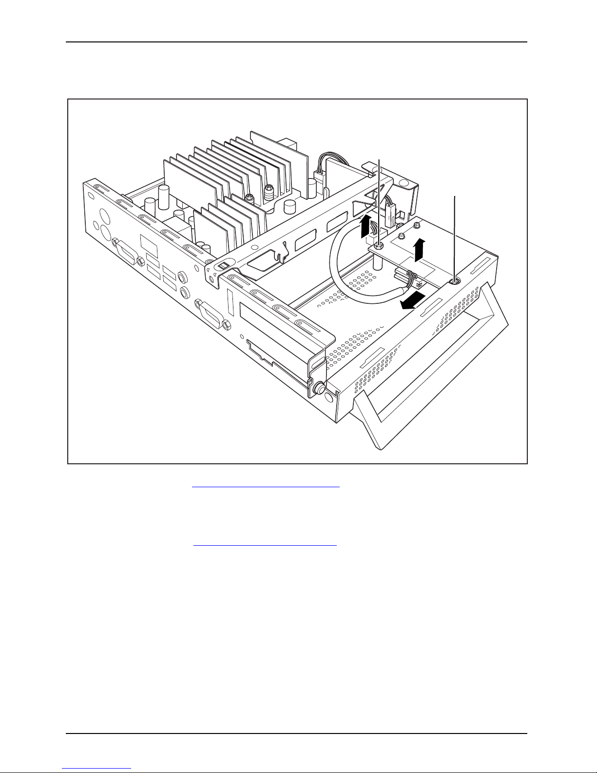
SmartCard-Leser einbauen
SmartCard-Leser
Sie können, sofern nicht bereits vorhanden, einen SmartCa rd-Leser einbauen.
1
2
4
4
4
3
► Schließen Sie die Leitung am SmartCard-Leser an (1) und schließen Sie die
Leitung am Stecker auf dem Mainboard an (2).
► Setzen Sie den SmartCard-Leser in Pfeilrichtung (3) mit der Bauteilseite
nach unten auf die Befestigungsbolzen.
► Befestigen Sie den SmartC ard-Leser mit den Schrauben (4) an der Halterung.
► Schließen Sie das Gehäuse (siehe "
Gehäuse schließen", Seite 20).
Achten Sie darauf, dass die Leitungen nicht zwischen Gehäuse und
Bauteilen eingeklemmt w erden !
A26361-K522-Z226-1-7419, Ausgabe 2 Deutsch - 21
Page 30

Systemerweiterungen
SmartCard-Leser ausbauen
SmartCard-Leser
1
2
4
3
3
► Öffnen Sie das Gehäuse (siehe "Gehäuse öffnen", Seite 19).
► Ziehen Sie die Leitung vom SmartCard-Leser (1) und vom Mainboard (2).
► Lösen Sie die Schrauben (3).
► Heben Sie den SmartCard-Leser von den Befestigungsbolzen ab (4).
► Schließen Sie das Gehäuse (siehe "
Gehäuse schließen", Seite 20).
22 - Deutsch A26361-K522-Z226-1-7419, Ausgabe 2
Page 31

Systemerweiterungen
Lithium-Batterie tauschen
Damit die Systeminformation dauerhaft gespeich ert werden kann, ist eine Lithium-Batterie
eingebaut, die den CMOS-Speicher mit Strom versorgt. Wenn die Spannung der Batterie
zu niedrig oder die Batterie leer ist, wird eine entsprechende Fehlermeldung ausgegeben.
Die Lithium-Batterie muss dann ausgetausch t w erden.
Bei unsachgemäßem Austausch der Lithium-Batterie besteht Explosionsgefahr!
Die Lithium-Batterie darf nur durch identische oder vom Hersteller
empfohlene Typen ersetzt werden.
Die L ithium-Batterie gehört nicht in den Hausmüll. Sie wird vom Hersteller,
Händler oder deren Beauftragten kostenlos zurückgenommen, um sie
einer Verwertung oder Entsorgung zuzuführen.
Achten Sie beim Austausch unbedingt auf die richtige Polung der
Lithium-Batterie, siehe Abbildung.
Lithium-BatterieTausch enWechselnAustauschen,Lithium-BatterieBatterie
Die Halterung der Lithium -Batterie gibt es in verschiedenen Ausf ührungen, die
sich in ihrer Funktionsweise nicht unterscheiden.
1
2
3
4
► Öffnen Sie das Geh äuse (siehe "Gehäuse öffnen", Seite 19).
► Drücken Sie die Rastnase in Pfeilrichtung (1).
Die Batterie springt etwas aus der Halterung heraus.
► Entfernen Sie die Batter ie (2 ).
► Schieben Sie die neue Lithium-Batterie des identischen Typs in die Halterung (3)
und drücken Sie sie nach unten , bis sie einrastet.
► Befestigen Sie die Rastnase (4).
► Schließen Sie das Gehäuse (siehe "
Gehäuse schließen", Seite 20).
A26361-K522-Z226-1-7419, Ausgabe 2 Deutsch - 23
Page 32

Technische Daten
Technische Daten
TechnischeDaten
Es dürfen nicht mehrere Geräte übereinander gestapelt werden.
Thin Client
Elektrische Daten
Prozessor:
AMD Sempron TF20
Nennspannung: 20 V
Maximaler Nennstrom: 3,25 A
Abmessungen
Breite/Tiefe/Höhe (mit Standfuß): 266 mm/97 mm/191 mm
Breite/Tiefe/Höhe (ohne Standfuß): 250 mm/52 mm/191 mm
Gewicht
im Grundausbau: ca. 1,6 kg (mit Standfuß)
Umgebungsbedingungen
Temperatur:
•Betrieb
• Transport
15 °C .... 35 °C
-25 °C .... 60 °C
Zu- und Ablufträume, um eine ausreichende Belüftung zu g ewährleisten:
• links min. 200 mm
• rechts min. 200 mm
•hinten min.200mm
•oben min.200mm
Betauung ist im Betrieb nicht zulässig!
Netzadapter
Elektrische Daten
Nennspannung: 100 - 240 V
Max. N ennstrom: 1,7 A
Nennfrequenz:
50 - 60 Hz
Es dürfen nur Adapter mit Limited Power Source werden:
• S26113-E519-V55 Model: ADP-65HB AD
• S26113-E519-V15 Model: 0335C2065
• S26113-E557-V55 Model: ADP-65JH AD
• S26113-E557-V65 Model: PA-1650-65
24 - Deutsch A26361-K522-Z226-1-7419, Ausgabe 2
Page 33

Contents
English
Contents
YourFUTRO S450... .................................................................... 1
Notational convention s .................................................................. 1
Importantnotes ........................................................................ 2
Safetyinformation ....................................................................... 2
Transportingthedevice .................................................................. 2
Cleaningthe device ..................................................................... 3
Energy saving, disposal
and recycling ....................................................
3
FCC Class B Compliance St
atement .....................................................
3
CEmarking ............................................................................ 4
Gettingstarted ......................................................................... 5
Ports and operating elements ........................................................... 5
Front view .......................................................................... 5
Rear view .......................................................................... 6
Settingup the device .................................................................... 7
Vertical operating position . ........................................................... 7
Horizontal operating position (optional) . . . . ............................................ 8
Connecting the monitor, mouse and keyboard . ............................................ 9
Connecting a m on itor . . . . . ........................................................... 9
Connecting the mouse . . . . ........................................................... 10
Connecting the k eyboard . ........................................................... 10
Connecting the device to the network (LAN) . . . ............................................ 10
Connecting external devices . . ........................................................... 11
Connecting the cables . .............................................................. 11
Disconnecting the cables . . . . . ....................................................... 11
Ports on the device .................................................................. 12
Connecting external devices to the serial interface . .................................... 12
Connecting external devices to the USB ports . ........................................ 13
Connecting microphone, headphones and line-out devices . ............................. 13
Connecting the mains adapter . ....................................................... 13
Operation .............................................................................. 14
Switch the
deviceon ....................................................................
14
Switching
offthe device .................................................................
14
Open BIOS S
etup .......................................................................
14
PXE syste
m boot . ......................................................................
14
Calling t
he PXE system boot configurationmenu .......................................
15
Systemexpansions .................................................................... 16
Information about boards . . . . . ........................................................... 16
Openingthe casing ..................................................................... 17
Closingthe casing ...................................................................... 18
Installing the SmartCard reader . . . ....................................................... 19
Removing the SmartCard reader . . ....................................................... 20
Replacingthelithiumbattery ............................................................. 21
Tech
nicaldata ........................................................................
22
A26361-K522-Z226-1-7419, edition 2 English
Page 34

Contents
English A26361-K522-Z226-1-7419, edition 2
Page 35

Your FUTRO S450...
Your FUTRO S450...
…is a universal network client. The intelligent, flexible terminal is reliable and easy
to maintain. The thin client requires no fan and no hard disk. It therefore runs very
quietly. The operating system is installed on a compact flash.
Notational conventions
Pay particular attention to text marked with this symbol. Failure to observe
these warnings could pose a risk to health, damage th e device or lead
to loss of data. The warranty will be invalidated if the device becomes
defective through failure to observe these warnings.
Indicates important information for the proper use of the device.
indicates information
affixed to the device , which is important for your health
or for preventing physi
cal damage.
►
indicates an activity th at m ust be perfo rmed
indicates the result of an action
This font
indicates data entered
using the keyboard in a program dialogue or at
the command line , e.g.
your password (Name123)oracommandusedto
start a program (star
t.exe)
This font
indicates informa tion that is displayed on the screen by a program, e.g.:
Installation is complete.
This font
indicates
• terms and text used in a software interface, e.g.: Click Save
• names of programs or files, e.g. Windows or setup.exe
"This font"
indicates
• cross-references to another section, e.g. "Safety information"
• cross-references to an external source, e.g. a web address: For more
information, go to"
http://ts.fujitsu.com"
• names of CDs, DVDs and titles or designations of other materials, e.g.:
"CD/DVD Drivers & Utilities" or "Safety" manual
Abc
indicates a key on the keyboard, e.g:
F10
This font
indicates terms and text that are emphasised or highlighted, e.g.: Do not
switch off the device
A26361-K522-Z226-1-7419, edition 2 English - 1
Page 36

Important notes
Important notes
ImportantnotesNotes
In this chapter you will find information regarding safety which it is essential to
take note of when working with your device.
Safety information
SafetyinformationNote
Pay attention to the information
provided in the "Safety" manua l
and in the following safety note
s.
When installing and operating th
e device, please observe the notes on
environmental conditions in Cha
pter "
Technical data ", Page 22 as well as
the instructions in Chapter "
Ge
tting started", Page 5.
Replace the lithium battery on th
e mainboard in accordance with the instructions
in the "
Replacing the lithium b
attery", Page 21 chapter.
The supplied pow er cable confo
rms to the requirements of the country in
which you purchased your devic
e. Make sure that the mains cable is approved
for use in the c ountry in which
you intend to use it.
The mains adapter’s power cabl
e should only be connected to a mains
socket if the device is connec
ted.
Do not use the mains adapter for
other devices.
Only use the mains adapter int
ended for use with the device, see
Chapter "
Technical data ", P
age 22.
Make sure that the rated curre
nt of the mains adapter is not higher than that of
the power system to which you
connect the mains adapter.
The ON/OFF switch does not ful
ly disconnect the TV from the mains
voltage. To completely disc
onnect the mains v oltage, remove the power
plug from the grounded mains
outlet.
Transporting the device
Device,TransportationRetransportation
Transport all parts separately in their original packaging or in a packaging which
protects them from knocks and jolts, to the new site.
Do not unpack them until all transportation manoeuvres are completed.
2 - English A26361-K522-Z226-1-7419, edition 2
Page 37

Important notes
Cleaning the device
Device,TransportationRetransportationSystemu nit,seeDevice
Turn off all power and equipment switches and remove the po wer
plug from the mains supply.
Do not clean any interior parts yourself, leave this job to a service technician.
Do not u se any cleaning agents that contain abrasives or may corrode plastic.
Ensure that no liquid enters the system.
Thesurfacecanbecleanedwithadry
cloth. If particularly dirty, use a cloth that has been
moistened in mild domestic deterge
nt and then carefully wrung out.
Use disinfectant wipes to clean the
keyboard and the mouse .
Energy saving, disposal and recycling
DisposalEnergysavingRecyclingDrivers&UtilitiesDVDUserDocumentationDVD
Further information can be found o n the "Drivers & Utilities" DVD.
FCC Class B Compliance Statement
The following statement applies to the p
roducts covered in this manual, unless otherwise specified
herein. The statement for other produc
ts w ill appear in the accompanying documentation.
NOTE:
This equipment has been tested and fou
nd to comply with the limits for a "Class B" digital
device, pursuant to Part 15 of the FCC r
ules and meets all requirements of the Canadian
Interference-Causing Equipment St
andard ICES-003 for digital apparatus. These limits are
designed to provide reasonable prot
ection against harmful interference in a residential installation.
This equipment generates, uses a nd c
an radiate radio frequency energy and, if not installed
and used in strict accordance with t
he instructions, may cause harmful interference to radio
communications. However, there
is no guarantee that interference will not occur in a particular
installation. If this eq uipme nt
does cause harmful interference to radio or television reception,
which can be determined by turnin
g the equipment off and on, the user is encouraged to
try to correct the interference
by one or more of the following measures:
• Reorient or relocate the receivi
ng antenna.
• Increase the sep aration between equipment and the receiver.
• Connect the equipment into an outl
et on a circuit different from that to
which the receiver is connected.
• Consult the dealer or an experienced radio/TV technician for help.
Fujitsu Technology Solutions Gm
bH is not responsible for any radio o r t elevision interference
caused by unauthorized modificat
ions of this equipment or the substitution or attachment
of connecting cables and equipm
ent other than those specified by Fujitsu Technology
Solutions GmbH. The correction
of interferences caused by such unauthorized modification,
substitution or attachment wil
l be the responsibility of the user.
The use of shielded I/O cables is
required when connecting this equipment to any and all optional
peripheral or host devices. F
ailure to do so may violate FCC and ICES rules.
A26361-K522-Z226-1-7419, edition 2 English - 3
Page 38

Important notes
CE marking
The shipped version of this device complies with the requirements of EEC
directives 2004/108/EC "Electromagnetic compatibility" and 2006/95/ EC
"Low voltage directive".
4 - English A26361-K522-Z226-1-7419, edition 2
Page 39

Getting started
Getting started
Gettingstarted
Please observe the safety information in the "Important notes", Page 2 chapter.
Ports and operating elements
Ports
This chapter presents the individual hardware c ompon ents of your device. This will p rovide
you with an overview of the ports and operating elements on the device. Please familiarise
yourself with these components before starting to work with your device.
Front view
OnswitchOffswitchPowerindicatorSmartCardreader,FlashmemoryaccessHeadphoneportAudiooutput,Mic rop honejackUSB,
5
4
3
2
6
7
1
1 = SmartCard reader
2 = Indicator for SmartCard read er
3 = Flash memory access
4 = Microphone jack
5 = USB ports (Universal Serial Bus)
6 = ON/OFF switch
7 = Headphones port, audio output (Line Out)
A26361-K522-Z226-1-7419, edition 2 English - 5
Page 40

Getting started
Rear view
RJ45-LANportPS/2mouseportInstallationopening,PS/ 2keyboardportMonitorportSerialportUSBportsAudiooutput,DCinput connector,Audioinput,KensingtonLock,
1
2
3
4
6
4
5
7
8
9
10
11
1 = Cover
2 = Serial port
3 = Audio output (Line Out)
4 = USB ports (Universal Serial Bus)
5 = DVI monitor port
6 = PS/2 key board port
7 = DC input connector (DC IN)
8 = Kensington lock device
9 = PS/2 mouse port
10 = RJ45 socket (Local Area N etwork)
11 = Audio input (Line In)
6 - English A26361-K522-Z226-1-7419, edition 2
Page 41

Getting started
Settingupthedevice
So that the casing is sufficiently ventilated and to prevent overheating, the
device may only be operated with the base foot attached.
Fit the base feet for horizontal or vertical operation ( see "Vertical operati ng position",
Page 7 and "Horizontal operating position (optional)", Page 8).
Base feet for horizontal operation are available as an option.
Vertical operating positi
on
Verticaloperatingpo
sition
Operatingposition,v
ertical
BasefeetSidecover
Use the supplied foot when the device is to be used in a vertical position.
Proceed as follows to operate the device in the vertical operating position:
► Disconnect the cables if required.
► Push the device onto the foot in the direction of the arrow.
► If necessary, rec
onnect any cables that were previously disconnected.
A26361-K522-Z226-1-7419, edition 2 English - 7
Page 42

Getting started
Horizontal operating position (optional)
Proceed as follows to operate the device in the horizontal operating position:
HorizontaloperatingpositionOperatingposition,horizontalBasefeet
► Disconnect the cables if re quired.
► Place the device on its upper side on a sturdy, flat and clean surface.
► Position the base feet on the underside of the device.
1
1
1
1
► Screw on the base feet with the screws (1).
► If necessary, reconnect an y cables that were previously disconnected.
8 - English A26361-K522-Z226-1-7419, edition 2
Page 43

Getting started
Connecting the monitor, mouse and keyboard
PS/2 keyboard port, purple USB port, black
(USB mouse , USB
keyboard)
DVI monitor port, white
PS/2 mouse port,
green
Connecting a monitor
► Follow the instructions contained in the monitor m anu al to prepare the monitor
for operation (e.g. connecting cables).
Monitor,
► Plug the data cable into the DVI monitor port of the device.
► Plug the monitor powe r cable into the grounded mains outlet.
A26361-K522-Z226-1-7419, edition 2 English - 9
Page 44
Getting started
Connecting the mouse
Mouse,Connecting,
Connecting a USB mouse
► Connect the U SB mouse to one of the USB ports on the device.
USBport,USBport
Connecting a PS/2 mouse
If you do not attach a mouse to the PS/2 mouse port, you can disable the mouse
controller in the BIOS Setup in order to free the IRQ12 for a different application.
► Connect the PS/2 mouse to the PS/2 mouse port of the device.
PS/2mouse,Connecting,PS/2mouse,
Connecting the keyboard
Keyboard,Connecting,
Connecting a USB keyboard
Use the supplied keyboard cable only.
USBport,Connecting,
► Plug the rectangular connector of the keyboa
rd cable into the rectangular socket
on the underside or on the rear of the keyboard
.
► Plug the flat rectangular USB co nnector of the keyboard cable into a USB port of the device.
USBport
Connecting a PS/2 keyboard
Use the supplied keyboard cable only.
ConnectingaPS/2keyboardConnecting,
► Plug the rectangular connector of the keyboard cable into the rectangular socket
on the underside or on the rear of the keyboard.
► Plug the round plug of the keyboard cable into th
e PS/2 keyboard port on the device.
Keyboard,
Connecting the device to the network (LAN)
LAN
► Connect the 10/100/1000 Base T network cable to the RJ45 LAN port.
10 - English A26361-K522-Z226-1-7419, edition 2
Page 45

Getting started
Connecting external devices
Read the documentation on the external device before connecting it.
With the exception of USB devices, always remove all power plugs
before connecting external devices!
Do not connect or disconnect cables during a thunderstorm.
Always take hold of the actual plug. Never unplug a cable by pulling the cab le itself.
Connect and disconnect the cables in the order described below.
Connecting the cables
► Turn off all power and equipment switches.
CordCable,
► Remove all power plugs from the grounded mains outlets.
► Connect all the cables to the device and the external devices. Please make sure that you
always obse rve the safety notes provided in "
Important notes", Page 2.
► Plug all data communication cables into the appropriate sockets.
► Plug all power cables into the grounded mains outlets.
USB devices are hot-pluggable. This means you can connect and disconnect
USB cables while your device is switched on.
Additional information can be found in "
Connecting external devices to the USB
ports", Page 13 and in the documentation for the USB devices.
Disconnecting the cables
► Switch off all affected devices
.
Cable,
► Remove all power plugs from the grounded mains outlets.
► Unplug all data communication cabl
es from the appropriate sockets.
► Disconnect all of the cables from the device and from the external devices.
A26361-K522-Z226-1-7419, edition 2 English - 11
Page 46

Getting started
Ports on the device
InterfacesExternaldevices,D evice,
The ports are located on the front and back of the device. The ports available on your
device depend on the configuration level you have selected. The standard ports are
marked with the symbols shown below (or similar). Detailed informat ion on the location
of the ports is provided in the manual for the mainboard.
Serial interface, turquoise
Serialinterface
Headphones port,
pink
Microphoneport
DVI monitor port, blue
Monitorport
Audio input (Line In),
light blue
AudioinputLinein
Microphone port, light
green
Headphones
Audio output (Line
Out), light green
AudiooutputLineou t
USB - Universal Serial
Bus, black
UniversalSerialBus
RJ45-LAN port
LANport
PS/2 mouse port, green
MouseportPS/2m ouseport
PS/2 keyboard port,
purple
Keyboardport
Some of the connected devices require special drivers (see the
documentation for the connected device).
Connecting external devices to the serial interface
SerialinterfaceSerialinterface,Externaldevices,Devices,
External devices can be connect
ed to the serial interface (e.g. a printer or modem).
► Connect the data cable to the ex
ternal device.
► Connect the data cable to the corresponding serial interf ace.
For an exact description of how t
o connect external devices to the corresponding
port, please see the external d
evice documentation.
Port settings
Serialinterface,
You can change the port settings
(e.g. address, interrupt) in the BIOS Setup.
Device drivers
Devi
cedrivers,
The devices connected to the serial interface require drivers. Your operating system
already includes many drivers. If the required drive is missing, install it. The latest
drivers are usually available on the Internet or will be supplied on a data carrier.
12 - English A26361-K522-Z226-1-7419, edition 2
Page 47

Getting started
Connecting external devices to the USB ports
USBdevices,USBport,Externaldevices,Devices,
You can conne ct a wide range of external devices to the USB ports (e.g.
printer, scanner, modem or keyboard).
USB devices are hot-pluggable. This means you can connect and disconnect
USB cables while your device is switched on.
Additional information can be found in the documentation for the USB devices.
► Connect the data cable to the external device.
► Connect the data cable to one of the USB ports on your device.
Device drivers
The external USB devices you connect to the USB ports usually require no
driver of their own, as the required software is already included in the opera ting
system. However, if the external USB device requires its own software, please
install it from the data carrier provided with the USB device.
To ensure USB 2.0, the length of the cable used between the front USB port o f
your device and the external USB device must not exceed 3 m.
Connecting microphone, headphones and line-out devices
MicrophoneH eadp honesLine-outdevices
► Connect the microphone to the microphone port.
► Connect the headphones to the headphones port.
► Connect line-out devices to the audio output.
► Connect the external line-in devices to the audio input.
Connecting the mains adapter
Mainsadapter
► Connect the mains adapter cable to the device.
► Connect the power cable to the mains adapter.
► Plug the power cable into a grounded mains outlet.
A26361-K522-Z226-1-7419, edition 2 English - 13
Page 48

Operation
Operation
Switch the device on
► If necessary, switch the monitor on (see the operating manu al for the monitor).
Device,Monitor,
► Switch on the device using the main
power switch located on the rear of the device (if present).
► Press the ON/OFF switch on the front of the device.
The power-on indicator lights gr
een and the device is started.
Switching off the device
► Shut down the operating system in a defined manner. In Windows: via the
Start menu and the Turn Off Computer function.
Device,Monitor,
► If the operating system does not au
tomatically switch the device into energy-saving mode or
switch it off, press the ON/OFF sw
itch. Warning, this could lead to a loss of data!
If the device is in s tandby, it consumes a minimum of energy.
► Switch the device off at the main s wi
tch (if present). The device no longer uses any power.
ThemainswitchandtheON/OFFswit
ch do not disconnect the device
from the mains voltage. To comple
tely disconnect the mains voltage,
remove the power plug from the p
ower socket.
► If necessary, switch the monitor off (see the operating manual for the monitor).
Open BIOS Setup
BIOS-Setup
► When the system starts, press the
F2
k
ey (several times if necessary).
BIOS Setup will be started. Select one of the tabs to access other setting options in BIOS Setup.
PXE system boot
PXEsyste
mboot
► Switch the devic e on with the ON/OF
Fswitch.
► When starting the syste m, press the
F12
key several times.
The boot menu is displayed.
► Select the desired boot option.
14 - English A26361-K522-Z226-1-7419, edition 2
Page 49

Operation
Calling the PXE system boot configuration menu
► Press the key combination
↑
+
F10
while Realtek RTL8139(X)/8130/810X Boot Agent is
displayed.
The following or a similar display appears on the screen:
Realtek RTL 8139 / 8130 / 810x BOOT Agent
Configuration Menu v2.13
Network Boot Protokol PXE [RLP]
Boot Order Int19h [PnP/BEV(BBS)
/ROM Disabled/
Int18h]
Show Config Message Enable [Disable]
Show Message Time 3 Seconds [5 / 8]
<ESC> <Space> <Enter> <F4>
Quit Change Value Next Option Save/Quit
Configuration menu s
creen.
The following settings are possible:
Network Boot
Protocol:
PXE (standard)
or RPL
Specification of the system boot protoco l used.
Boot Order: Int 19h
The network is always started first before the local
devices are activated.
PnP/ BEV (BBS)
If a BBS-BIOS (BIOS Boot Specification) exists,
the system is started by the BBS-BIOS.
ROM Disabled
The entire mechanism for the system boot is
deactivated. The system can only be activated via
the local devices.
Int 18h
The devices set in BIOS Setup are enabled.
Show Config
Message:
The following message can be activated or deactivated during the
system boot:
Realtek RTL8139(X)/8130/810X Boot Agent Press Shift-F10
to configure …….
Show
Message
Time:
Indicates the time in seconds for which the following message is
displayed during the system boot:
Realtek RTL8139(X)/8130/810X Boot Agent Press Shift-F10
to configure …….
The settings are not effective until after saving and another PXE system boot.
A26361-K522-Z226-1-7419, edition 2 English - 15
Page 50

System expansions
System expansions
Upgrades,D evice,System expansion
You can also insta ll the following optional compo nents:
As the device has to be shut down in order to install/uninstall system hardware
components, it is a good idea to print out the relevant sections of this chapter.
An update of the BIOS may be required for a system expansion or hardware
upgrade. Further information can be found in the BIOS help section or if
necessary in the Technical Manual for the mainboard.
When installing components that become very hot, make sure that the
maximum permissible temperature is not exceeded.
The device must be switched off when installing/removing the system
expansions and may not be in energy-saving mode.
Remove the power plug before opening the device.
This chapter describes all the activities required to modify your device hardware
(e.g. installing boards or drives).
Read the supplied documentation be fore installing new drives and/or boards.
Refer to the manual for the mainboard before making any extensions to the mainboard.
Information about boards
Take care with the locking mechanisms (catches and centring pins) when you
are replacing boards or components on boards
To prevent damage to the board or the c ompo nent s and conductors on it, please take care when
you insert or remove boards. Make s ure expansion boards are inserted straightly.
Never use sharp objects (screwdrivers) for leverage.
Boards with electrostatic s
ensitive devices (ESD) are identifiable by the label
shown.
When handling boards fitted w
ith ESDs, you must always observe the
following points:
• You must always discharge st
atic build up (e.g. by tou ching a grounded
object) before working.
• The equipment and tools you use must be free of static charges.
• Always hold boards by their
edges.
• Never touch pins or conductors on boards fitted with E SDs .
16 - English A26361-K522-Z226-1-7419, edition 2
Page 51

System expansio ns
Opening the casing
Casing,Device ,
Note that some components on the mainboard may be very hot if the device was in
use shortly before the casing was removed.
These components can be marked with the following symbol.
► Switch the device off. The device must not be in p ower-saving mode.
Please observe the safety information in "Importan t notes", Page 2.
Disconnect the mains plug from the mains outlet.
Only insert the power plug after you have closed the casing.
► Remove any connected w ires which are in the way.
3
22
11
► Loosen the screws at the rear (1).
► Push the casing cover forward (2).
► Lift off the casing cover (3).
A26361-K522-Z226-1-7419, edition 2 English - 17
Page 52

System expansions
Closing the casing
CasingCasingcover
► Replace the casing cover on the device and push it backwards.
► Secure the casing cover with the two screws on the rear of the device.
Make sure that the cables are not trapped between the casing a nd the components.
► Connect all the cables removed b
efore.
18 - English A26361-K522-Z226-1-7419, edition 2
Page 53

System expansio ns
Installing the SmartCard reader
SmartCardreader
If not already installed, you can fit a SmartCard reader.
1
2
4
4
4
3
► Connect the cable to the SmartCard reader (1) and to the connector on the mainboard (2).
► With the compo
nent side facing downwards, insert the SmartCard re ader on
the securing b
olt in the direction of the arrow (3).
► Secure the S ma rtCard reader onto the carrier with the screws (4).
► Close the casin
g (see "
Closing the casing", Page 18).
Make sure that
the cables are not trapped between the casing and the c omponen ts.
A26361-K522-Z226-1-7419, edition 2 English - 19
Page 54
System expansions
Removing the SmartCard reader
SmartCardreader
1
2
4
3
3
► Open the casing (see "Opening the casing", Page 17).
► Disconnect the cable from the SmartCard reader (1) and from the mainboard (2).
► Loosen the screws (3).
► Lift the SmartCard reader from the securing bo lt (4).
► Close the casing (see "
Closing the casing", Page 18).
20 - English A26361-K522-Z226-1-7419, edition 2
Page 55

System expansio ns
Replacing the lithium battery
In order to permanently save the system information, a lithium battery is installed to provide
the CMOS-memory with a current. A correspond ing error message notifies the user when the
charge is too low or the battery is empty. The lithium battery must the n be replaced.
Incorrect replacement of the lithium battery may lead to a risk of explosion!
The lithium batte ry may be replaced only with an identical battery or with
a type recommended by the manufacturer.
Do not dispose of lithium batteries with household waste. They must be disposed
of in accordance with local regulations concerning special w aste.
When replacing the Lithium battery, make sure that you insert it the
right way round, see diagram.
Lithiumbattery,Replacing,Replacing,Replacing,lithiumbatteryBattery
The lithium battery holder exists in different designs that fu nction in the same way.
1
2
3
4
► Open the casing (see "Opening the casing", Page 17).
► Press the catch in the direction of the arrow (1).
The battery jumps out of the holder slightly.
► Remove the battery (2).
► Push the new lithium battery of the identical type into the holder (3) and
press it down until it engages.
► Fasten the catch (4).
► Close the casing (see "
Closing the casing", Page 18).
A26361-K522-Z226-1-7419, edition 2 English - 21
Page 56

Technical data
Technical data
Technicaldata
Do not stack several devices o n top of each other.
Thin Client
Electrical data
Processor:
AMD Sempron TF20
Rated voltage: 20 V
Max. rated current: 3.25 A
Dimensions
Width/depth/height (with base foot): 2 66 mm/97 mm/191 mm
Width/depth/height (without base foot): 250 mm/52 mm/191 mm
Weight
in basic configuration: approx. 1.6 kg (including foot)
Ambient condit ions
Temperature:
• Operation
• Transportation
15 °C .... 35 °C
-25 °C .... 60 °C
Clearance required to ensure adequate ventilation:
•left
min. 200 mm
• right-hand side min. 200 mm
• rear
min. 200 mm
•top
min. 200 mm
Condensation must be avoided during operation.
Mains adapter
Electrical data
Rated voltage: 100 - 240 V
Max. rated current: 1.7 A
Rated frequency:
50 - 60 Hz
Only adapters with Limited Power Source may be used:
• S26113-E519-V55 Model: ADP-65HB AD
• S26113-E519-V15 Model: 0335C2065
• S26113-E557-V55 Model: ADP-65JH AD
• S26113-E557-V65 Model: PA-1650-65
22 - English A26361-K522-Z226-1-7419, edition 2
 Loading...