

Page 1
Mini-ITX D2963-SMini-ITX D2963-S
TechNotesV1.0
First Release
Mainboard OEM Sales -01/2010
Page 2
ContentContent
Safety Instructions à Page 2
•
•Mainboard Overview & Benchmarks à Page 3
•Display Options à Page 10
•Power Supply Features à Page 25
•Internal Connectors à Page 35
•System Monitoring à Page48
•Temperature Reference Overview à Page 63
•Mainboard Power Consumption à Page 66
•Special Features à Page 68
•Operating System Support à Page 71
•OEM FTP download link for D2963-S
ftp://ftp.ts.fujitsu.com/pub/Mainboard-OEM-Sales/Products/Mainboards/Industrial&ExtendedLifetime/D2963-S/
(provides BIOS; Drivers; Documents & Approvals; Specifications; Tools etc.)
1
TechNotes_D2963_V1.0 Copyright 2010 FUJITSU LIMITED
Page 3
SafetyInstructionsSafetyInstructions
Do not connect or disconnect any cables or modules to or from any onboard connectors
(except for the rear I/O connectors) until the mainboard is completely powered down.
Any damage caused to the mainboard by misuse of the onboard connectors is
excluded from the standard warranty. Fujitsu Technology Solutions cannot be held
liable for any damage that results from incorrect use of any onboard connectors.
The system integrator is fully responsible for the usage of appropriate connectors and
cables in order to fulfill the technical requirements (electrical contact, durability,
power/current levels, signal integrity etc.)
2
TechNotes_D2963_V1.0 Copyright 2010 FUJITSU LIMITED
Page 4
Overview
•Onboard interfaces & connectors
3
TechNotes_D2963_V1.0 Copyright 2010 FUJITSU LIMITED
Page 5
Overview
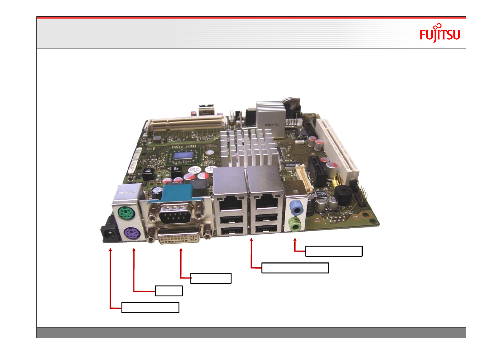
Overview
OnboardComponents
OnboardComponents
2 x PS/2
DC-IN (+ 19…24V)
COM1 / DVI-I
Dual-LAN / 4 x USB 2.0
4
TechNotes_D2963_V1.0 Copyright 2010 FUJITSU LIMITED
Stereo Audio In/Out
PCB: 8-layer
Page 6
Overview
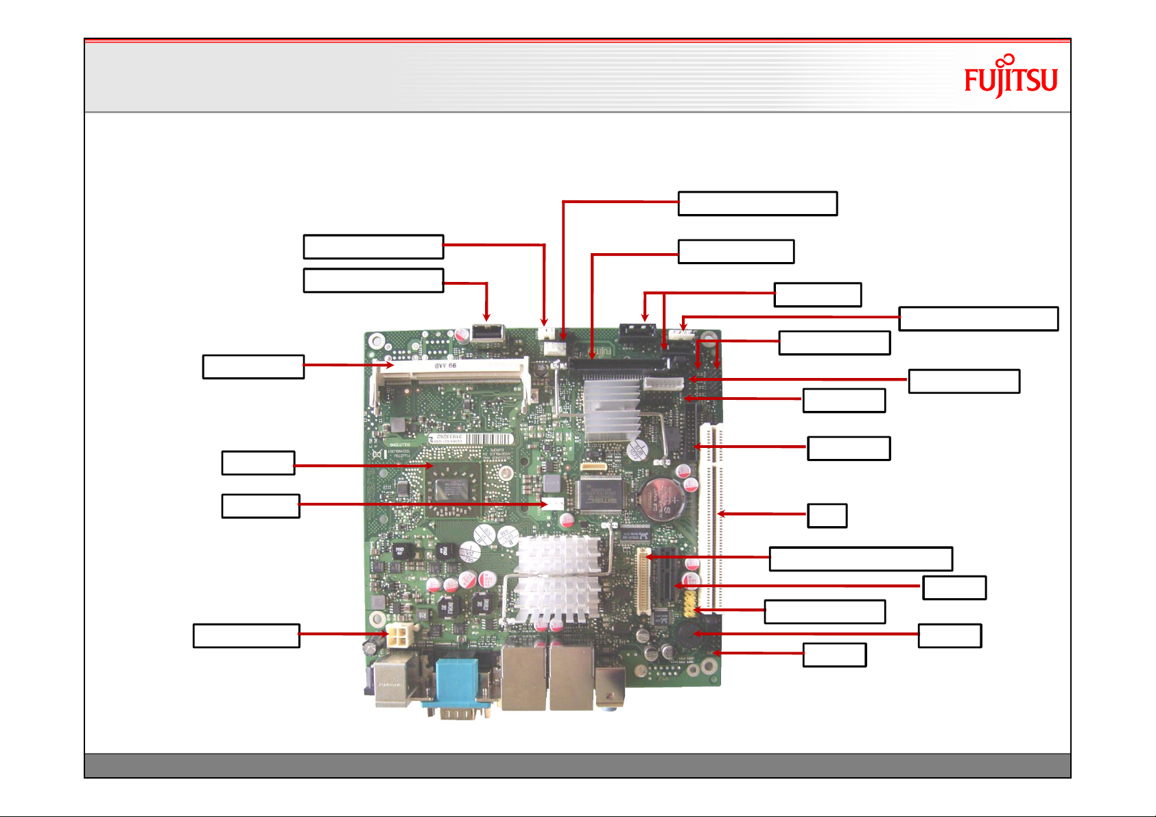
Overview
OnboardComponents
OnboardComponents
Chassis Fan Connector
1 x SO-DIMM
Processor
CPU Fan
19…24V DC-In
Intrusion Connector
USB Stick Connector
Compact Flash
2 x SATA II
Drive Power Connector
2 x 2 USB Ports
LVDS-Backlight
Frontpanel
GPIO Port
PCI
24 Bit Dual Channel LVDS
PCIe X1
FrontpanelAudio
Buzzer
COM 2
5
TechNotes_D2963_V1.0 Copyright 2010 FUJITSU LIMITED
Page 7
Overview
Overview
OnboardComponents
OnboardComponents
Mini PCI Express Connector (incl. USB support)
MechanicalLock for
Mini PCI Express Card
Sample forWLAN Minicardon D2963-S
MechanicalLock
(supportsfullsizecardsonly!)
6
TechNotes_D2963_V1.0 Copyright 2010 FUJITSU LIMITED
Page 8
Overview
Overview
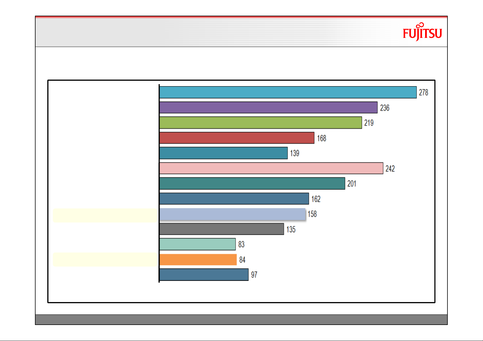
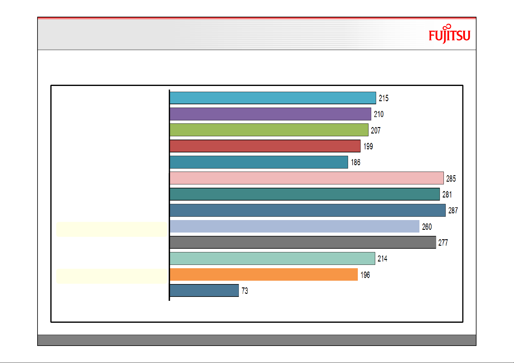
Benchmarks –SysMark2004SE (Overall Rating)
Benchmarks –SysMark2004SE (Overall Rating)
Intel Core 2 Duo T7200 / i945GM
2 GHz / 4MB L2 / 34W TDP
Intel Core 2 Duo T2500 / i945GM
2 GHz / 2MB L2 / 31W TDP
Intel Core 2 Duo T2400 / i945GM
1.83GHz / 2MB L2 / 31W TDP
Intel Core Solo T1300 / i945GM
1.66GHz / 2MB L2 / 31W TDP
Intel Celeron-M 420 / i945GM
1.6GHz / 1MB L2 / 27W TDP
AMD TurionTL-68 / D2703-S
2.4GHz / 1MB L2 / 35W TDP
.
AMD TurionTL-56 / D2703-S
1.8GHz / 1MB L2 / 31W TDP
.
Sempron 3700+ / D2703-S
2.0GHz / 512KB L2 / 25W TDP
AMD AthlonNeo X2 L325 / D2963-S2
1.5GHz / 1MB L2 / 18W TDP
.
.
1)
AthlonTF-20 / D2703-S
1.6GHz / 512KB L2 / 15W TDP
.
AMD Sempron2100+ / D2703-S
1.0GHz / 256KB L2 / 8W TDP
AMD Sempron200U / D2903-S1
1.0GHz / 256KB L2 / 8W TDP
Intel Atom N270/945GSE
1.6GHz / 512KB L2 / 2.5W TDP
.
.
1)
1)
System configuration: 2 x 512MB @ max. memory speed
1) Intel Atom and D2963-S: 1 x 1GB (1 socket only)
7
TechNotes_D2963_V1.0 Copyright 2010 FUJITSU LIMITED
Page 9
Overview
Overview
Benchmarks –3DMark2006
Benchmarks –3DMark2006
Intel Core 2 Duo T7200 / i945GM
2 GHz / 4MB L2 / 34W TDP
Intel Core 2 Duo T2500 / i945GM
2 GHz / 2MB L2 / 31W TDP
Intel Core 2 Duo T2400 / i945GM
1.83GHz / 2MB L2 / 31W TDP
Intel Core Solo T1300 / i945GM
1.66GHz / 2MB L2 / 31W TDP
Intel Celeron-M 420 / i945GM
1.6GHz / 1MB L2 / 27W TDP
AMD TurionTL-68 / D2703-S
2.4GHz / 1MB L2 / 35W TDP
.
AMD TurionTL-56 / D2703-S
1.8GHz / 1MB L2 / 31W TDP
.
Sempron 3700+ / D2703-S
2.0GHz / 512KB L2 / 25W TDP
AMD AthlonNeo X2 L325 / D2963-S2
1.5GHz / 1MB L2 / 18W TDP
.
.
1)
AthlonTF-20 / D2703-S
1.6GHz / 512KB L2 / 15W TDP
.
AMD Sempron2100+ / D2703-S
1.0GHz / 256KB L2 / 8W TDP
AMD Sempron200U / D2903-S1
1.0GHz / 256KB L2 / 8W TDP
Intel Atom N270/945GSE
1.6GHz / 512KB L2 / 2.5W TDP
.
.
1)
1)
System configuration: 2 x 512MB @ max. memory speed
1) Intel Atom and D2963-S: 1 x 1GB (1 socket only)
8
TechNotes_D2963_V1.0 Copyright 2010 FUJITSU LIMITED
Page 10
Overview
Overview
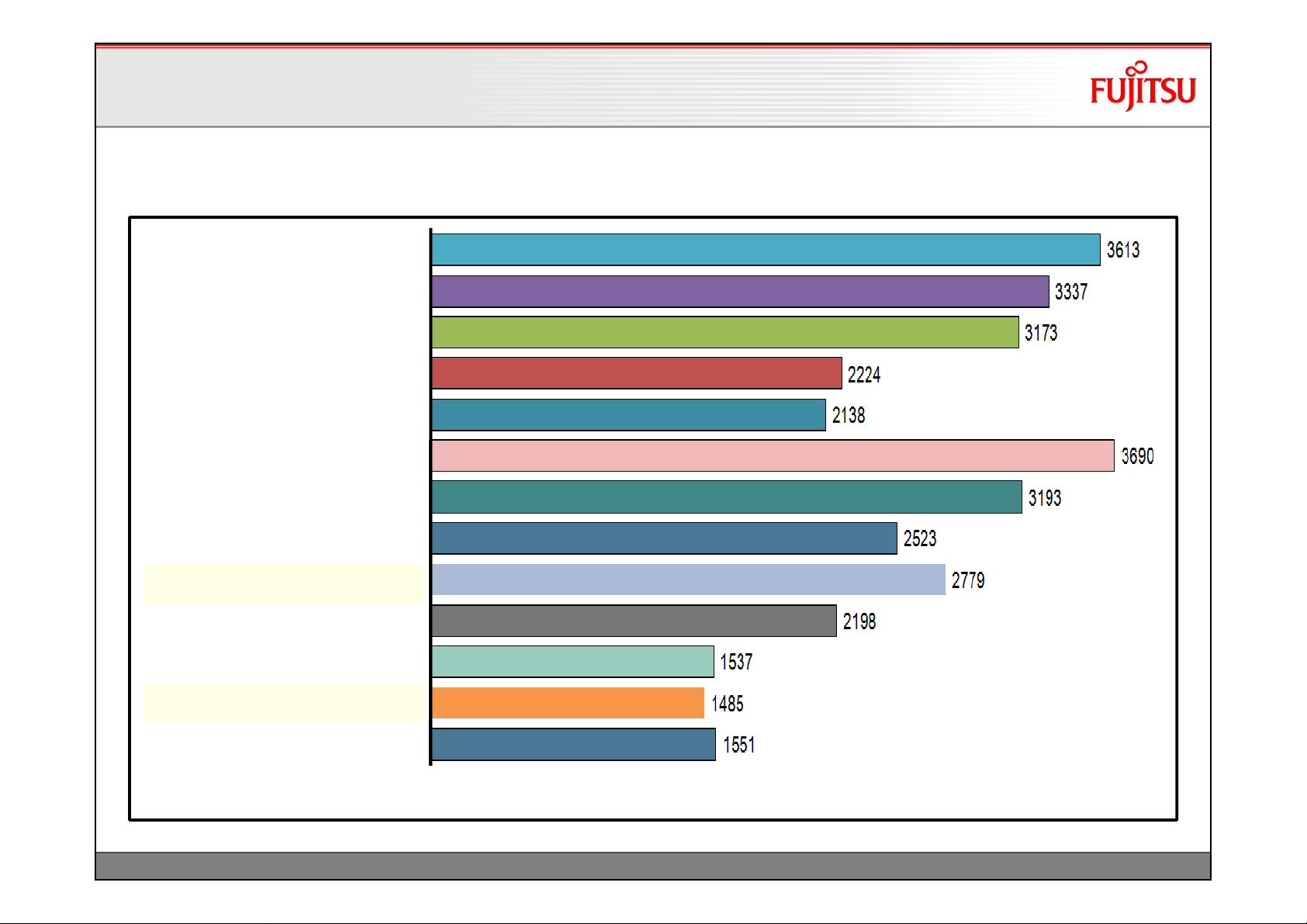
Benchmarks –PCMark2005
Benchmarks –PCMark2005
Intel Core 2 Duo T7200 / i945GM
2 GHz / 4MB L2 / 34W TDP
Intel Core 2 Duo T2500 / i945GM
2 GHz / 2MB L2 / 31W TDP
Intel Core 2 Duo T2400 / i945GM
1.83GHz / 2MB L2 / 31W TDP
Intel Core Solo T1300 / i945GM
1.66GHz / 2MB L2 / 31W TDP
Intel Celeron-M 420 / i945GM
1.6GHz / 1MB L2 / 27W TDP
AMD TurionTL-68 / D2703-S
2.4GHz / 1MB L2 / 35W TDP
.
AMD TurionTL-56 / D2703-S
1.8GHz / 1MB L2 / 31W TDP
.
Sempron 3700+ / D2703-S
2.0GHz / 512KB L2 / 25W TDP
.
AMD AthlonNeo X2 L325 / D2963-S2
1.5GHz / 1MB L2 / 18W TDP
.
.
1)
AthlonTF-20 / D2703-S
1.6GHz / 512KB L2 / 15W TDP
.
AMD Sempron2100+ / D2703-S
1.0GHz / 256KB L2 / 8W TDP
AMD Sempron200U / D2903-S1
1.0GHz / 256KB L2 / 8W TDP
Intel Atom N270/945GSE
1.6GHz / 512KB L2 / 2.5W TDP
.
.
1)
1)
System configuration: 2 x 512MB @ max. memory speed
1) Intel Atom and D2963-S: 1 x 1GB (1 socket only)
9
TechNotes_D2963_V1.0 Copyright 2010 FUJITSU LIMITED
Page 11

Display Options
• LVDS display & backlight inverter
• LVDS / Inverter connector details
• LVDS timings & screen resolutions
• LVDS cabling reference
• DVI, VGA, HDMI, LVDS
10
TechNotes_D2963_V1.0 Copyright 2010 FUJITSU LIMITED
Page 12
Display Options
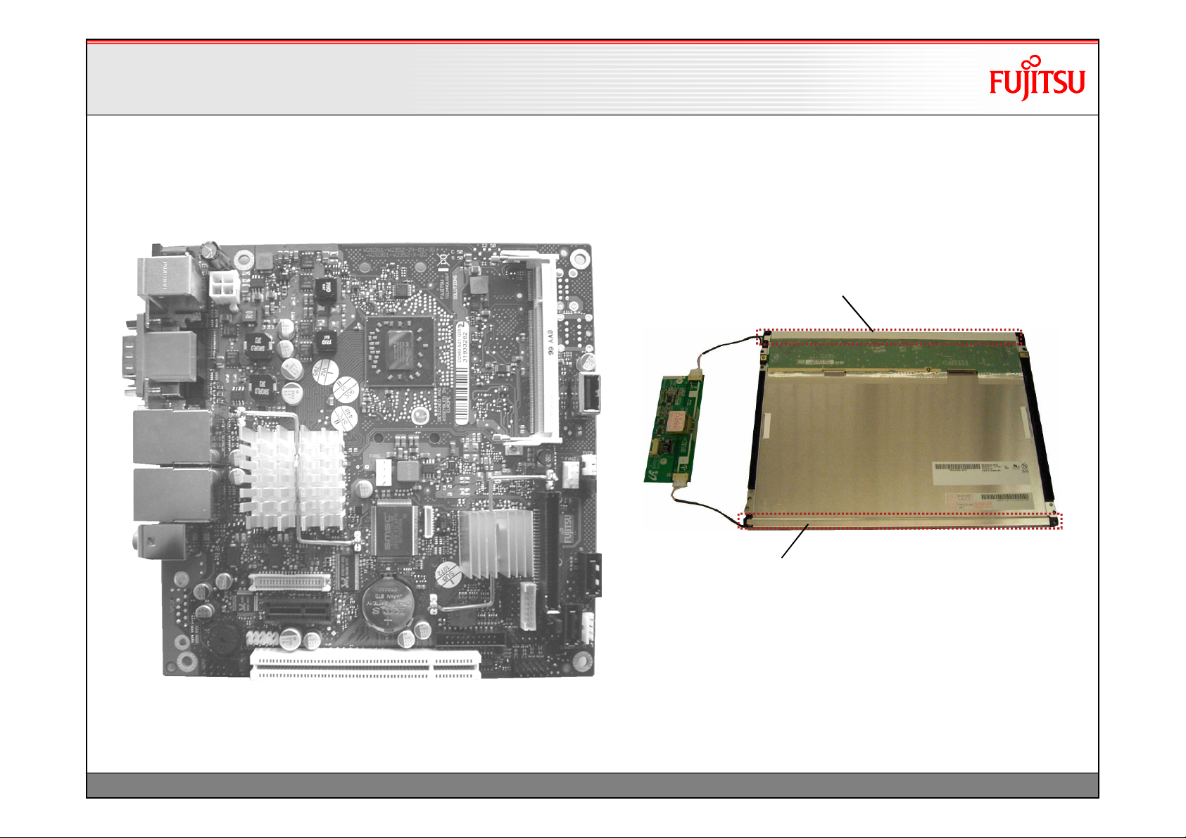
Display Options
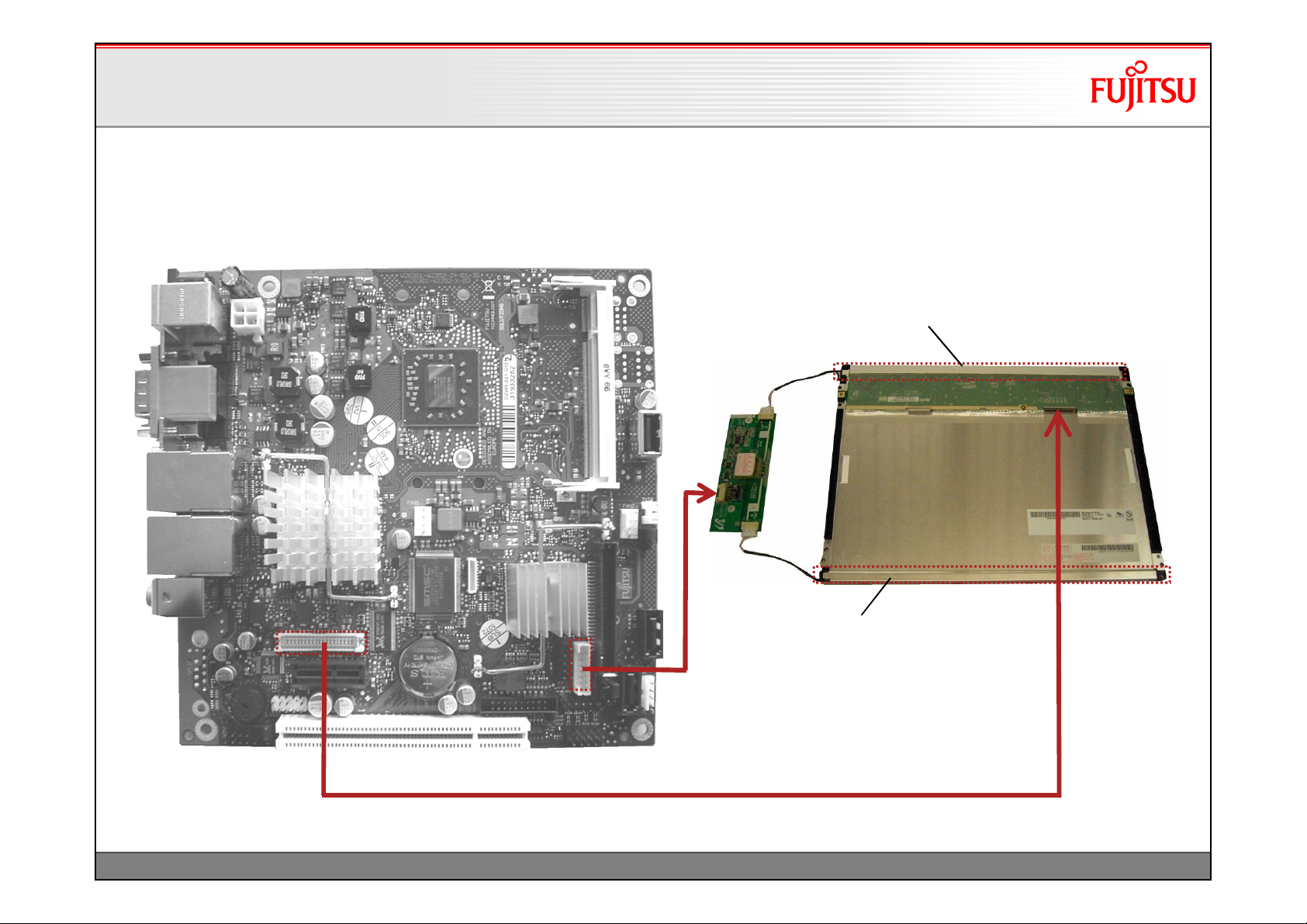
LVDS Display & Backlight Inverter
LVDS Display & Backlight Inverter
Backlight
Integrated Backlight, powered by Inverter
Inverter
LVDS Display
(rear view)
11
Integrated Backlight,
powered by Inverter
TechNotes_D2963_V1.0 Copyright 2010 FUJITSU LIMITED
Page 13
Display Options
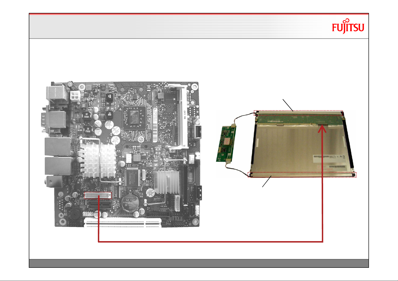
Display Options
LVDS Display & Backlight Inverter
LVDS Display & Backlight Inverter
Backlight
Integrated Backlight, powered by Inverter
Inverter
LVDS Display
(rear view)
12
Integrated Backlight,
powered by Inverter
LVDS Data / Power for display
TechNotes_D2963_V1.0 Copyright 2010 FUJITSU LIMITED
Page 14
Display Options
Display Options
LVDS Display & Backlight Inverter
LVDS Display & Backlight Inverter
Backlight
Integrated Backlight, powered by Inverter
Inverter
LVDS Display
(rear view)
13
Integrated Backlight,
for Inverter
Control / Power
LVDS Data / Power for display
TechNotes_D2963_V1.0 Copyright 2010 FUJITSU LIMITED
powered by Inverter
Page 15
PIN
SIGNAL
SIGNAL
PIN
1)
1)
35
1)
37
Display Options
Display Options
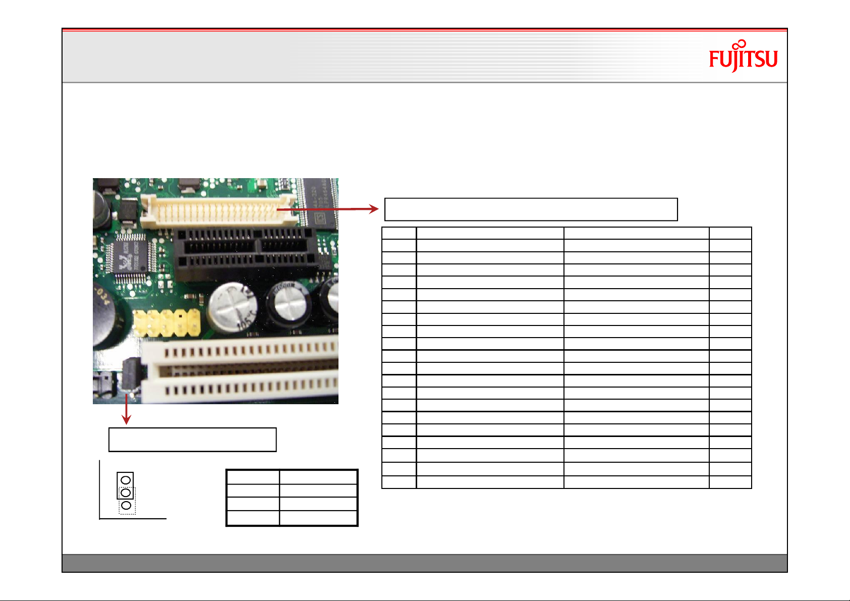
LVDS Connector Details
LVDS Connector Details
1
2
3
1
LVDS voltage selector jumper
3.3V (default)
5V (optional)
Pin Signal
3 VCC 3.3V
2 Power LVDS
1 VCC 5V
LVDS Connector: Hirose DF13-40 (or compatible)
2 Ground Ground 1
4 LVDS_H3+ (EVEN_3+) LVDS_L3+ (ODD_3+) 3
6 LVDS_H3- (EVEN_3-) LVDS_L3- (ODD_3-) 5
8 Ground Ground 7
10 LVDS_H2+ (EVEN_2+) LVDS_L2+ (ODD_2+) 9
12 LVDS_H2- (EVEN_2-) LVDS_L2- (ODD_2-) 11
14 Ground Ground 13
16 LVDS_H1+ (EVEN_1+) LVDS_L1+ (ODD_1+) 15
18 LVDS_H1- (EVEN_1-) LVDS_L1- (ODD_1-) 17
20 Ground Ground 19
22 LVDS_H0+ (EVEN_0+) LVDS_L0+ (ODD_0+) 21
24 LVDS_H0- (EVEN_0-) LVDS_L0- (ODD_0-) 23
26 Ground Ground 25
28 LVDS_CLK_H+ (CLK_EVEN+) LVDS_CLK_L+ (CLK_ODD+) 27
30 LVDS_CLKH- (CLK_EVEN-) LVDS_CLK_L- (CLK_ODD-) 29
32 Ground Ground 31
34 DDC-Data DDC-Clock 33
36
38 Ground
40 LCD_Power_Enable Ground 39
LCD-Power
LCD-Power
LCD-Power
1) selectable via Jumper
max. load: 1A per pin!
14
TechNotes_D2963_V1.0 Copyright 2010 FUJITSU LIMITED
Page 16
Display Options
Display Options
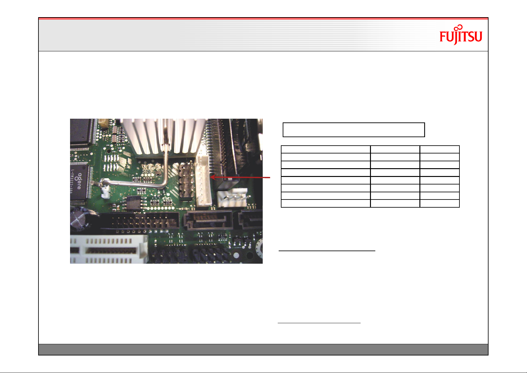
Backlight Inverter Connector Details
Backlight Inverter Connector Details
Backlight Inverter Connector: JST PHR-8
8
1
Backlight Brightness CTRL tbd 3
Backlight On/Off Control BL On/Off 6
Ground GND 1
Ground GND 2
Power 5V VCC 4
Power 5V VCC 5
Power 12V +12V 7
Power 12V +12V 8
max. load: 2A per pin!
15
Note:
BacklightBrightnessControl: Providesa variable DC voltage
between 0V and ~ 3.5V via an RC filter (2,2kOhm / 20uF).
Basically the voltage level can be selected via BIOS
Setup –Peripheral Configuration –Brightness Control.
If this control signal is used, the system integrator is
responsible for the implementation of a backlight converter
that fits to the control output voltage range.
Backlight On/Off Control:Active High, 3.3V
Note: Polarity can be changed via BIOS Setup
(Not supported by pilot production mainboardsGS5x!)
TechNotes_D2963_V1.0 Copyright 2010 FUJITSU LIMITED
Page 17
Display Options
Display Options
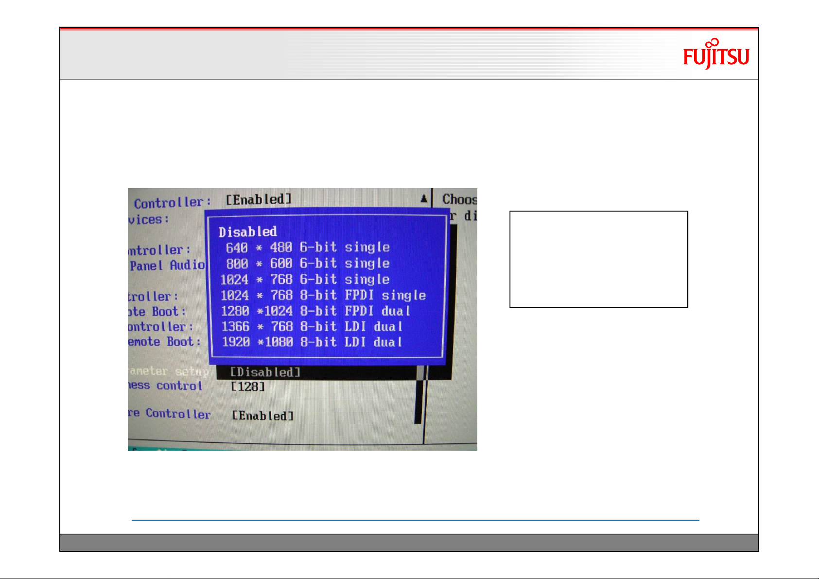
LVDS Timing & Screen Resolution
LVDS Timing & Screen Resolution
Available default LVDS settings (BIOS Setup –Advanced –Peripheral Configuration)
•
Detailed information (timing,
pixels etc.) about each LVDS
default setting is available in
the related configuration files
of the tool LVDS.EXE (see
following page)
max. LVDS screen resolution:
2048 x 1536 / 32bit color
Note:
Default BIOS Setting for LVDS is “Disabled”.
Any BIOS Setup changes can be fixed as new default BIOS setting via BIONVD tool!
ftp://ftp.ts.fujitsu.com/pub/Mainboard-OEM-Sales/Services/Software&Tools/Common-Mainboard-Tools/ChangeBIOS-Setup-Defaults/
16
TechNotes_D2963_V1.0 Copyright 2010 FUJITSU LIMITED
Page 18
Display Options
Display Options
LVDS Timing & Screen Resolution
LVDS Timing & Screen Resolution
• DOS-Tool LVDS.EXE V1.01 allows to adjust LVDS timing parameters
•Download link
ftp://ftp.ts.fujitsu.com/pub/Mainboard-OEM-Sales/Products/Mainboards/Industrial&ExtendedLifetime/D2963-S/IndustrialTools_D2963-
S/LVDS-Tool/
•Select one of the seven default configuration files as master file
(Note: These default files are based on the seven BIOS Setup default LVDS settings)
•Rename selected file to panel.txt
•Edit file panel.txt according to required settings and save file
•Run following operation on target system (DOS-mode required!):
lvds-v -cf=panel.txt (= DOS Batch-File "Set-LVDS.bat")
•Change BIOS Setup
Advanced \Peripheral Configuration
LCD Parameter setup --> User Defined
•Save settings and reboot system
•Note: In order to remove the "User defined" LVDS setting in BIOS Setup,
run the DOS Batch-File "Remove.bat"
17
TechNotes_D2963_V1.0 Copyright 2010 FUJITSU LIMITED
Page 19
Display Size
TFT
Pixel
Inverter
Display Options
Display Options
LVDS Cabling Reference
LVDS Cabling Reference
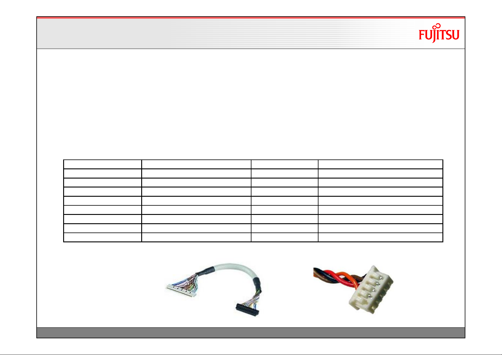
• Sample cabling diagrams for following LVDS displays & related
inverters are available:
10.4" NEC NL6448BC33-63D 640 x 480 NEC 104PW201
12.1" AUO G121SN01-V0 800 x 600 Green-C&C GH093A-ROHS
12.1" LG-Philips LB121S03-TL01 800 x 600 Green-C&C GH001HB-ROHS
15" Sharp LQ150X1LW71N 1024 x 768 TDK CXA-0349
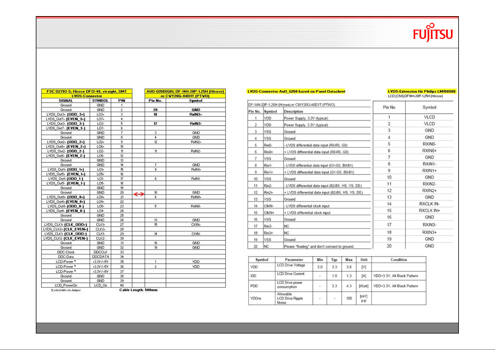
15" AUO G150XG01V0 1024 x 768 Green-C&C GH001A-ROHS
17" AUO M170EG01-VD 1280 x 1024 Green-C&C GH053A-ROHS
19" Sharp LQ190E1LW01 1280 x 1024 Power Systems PS-DA0412-05
19" AUO M190EG01 1280 x 1024 GH053(A1)-ROHS
18
TechNotes_D2963_V1.0 Copyright 2010 FUJITSU LIMITED
Page 20
Display Options
Display Options
LVDS Sample Cabling for AuO-G150
LVDS Sample Cabling for AuO-G150
19
TechNotes_D2963_V1.0 Copyright 2010 FUJITSU LIMITED
Page 21
Display Options
Display Options
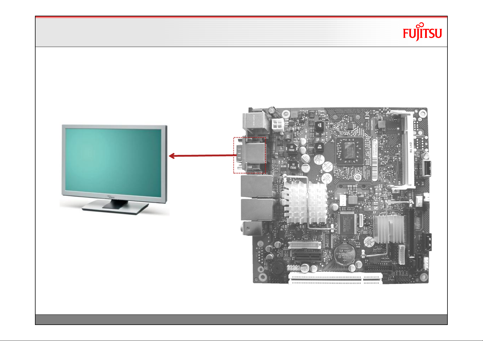
DVI Output
DVI Output
Digital (DVI) Monitor
max. DVI screenresolution:
2560 x 1600 / 32bit color(Dual Link)
1600 x 1200 / 32bit color (Single Link, standard timings)
1920 x 1200 / 32bit color (Single Link, reduced blanking timings)
20
TechNotes_D2963_V1.0 Copyright 2010 FUJITSU LIMITED
Page 22
Display Options
Display Options
HDMI Output (w/o audio!)
HDMI Output (w/o audio!)
Digital (HDMI) Monitor
via DVI/HDMI interface connector
max. HDMI screenresolution: 1080i
Note:
OnlyHDMI graphicssupported, noaudiotransmission!
21
TechNotes_D2963_V1.0 Copyright 2010 FUJITSU LIMITED
Page 23
Display Options
Display Options
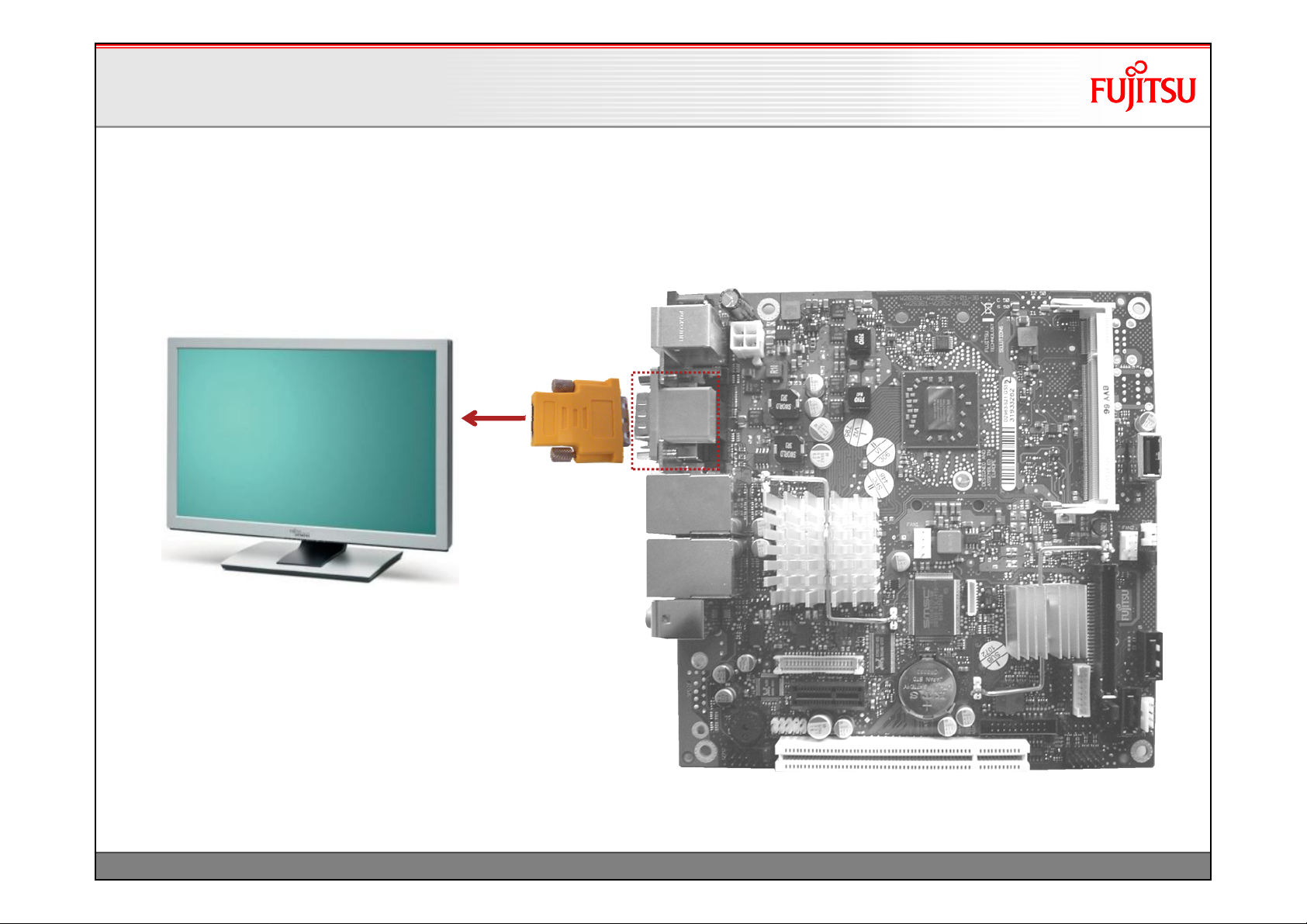
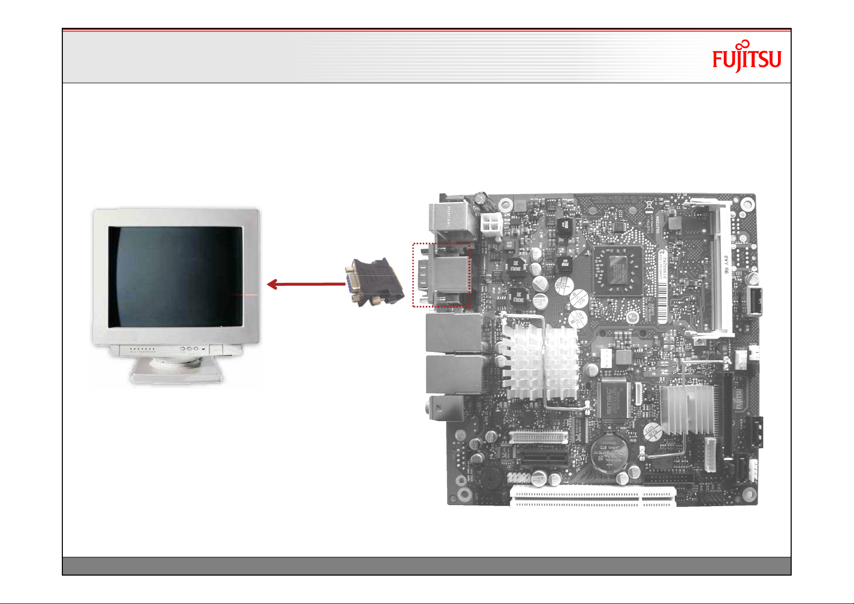
VGA Output via Interface Connector
VGA Output via Interface Connector
Analog (VGA) Monitor
via DVI/VGA interface connector
max. VGA screenresolution:
2048x1536 @85Hz for4:3 format
2560x1440 @75Hz for16:9 format
2456x1536 @60Hz for16:10 format
22
TechNotes_D2963_V1.0 Copyright 2010 FUJITSU LIMITED
Page 24
Display Options
Display Options
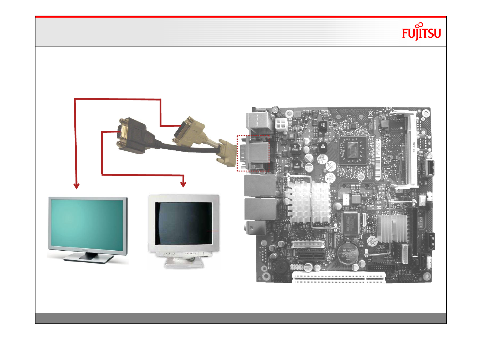
DVI & VGA via Splitter Cable
DVI & VGA via Splitter Cable
Analog (VGA) Monitor and Digital (DVI) Monitor
via DVI/VGA splitter cable
Dual Independent Display Option
(Note: DVI –single link only via splitter cable!)
23
TechNotes_D2963_V1.0 Copyright 2010 FUJITSU LIMITED
Page 25

Display Options
Display Options
DVI or VGA plus LVDS
DVI or VGA plus LVDS
or
Analog (VGA) Monitor or
Digital (DVI) Monitor;
plus LVDS Display
Dual Independent Display Option
max. LVDS screenresolution:
2048 x 1536 / 32bit color
24
TechNotes_D2963_V1.0 Copyright 2010 FUJITSU LIMITED
Page 26

Power Supply Features
•19-24V DC power supply
•Drive power connector
25
TechNotes_D2963_V1.0 Copyright 2010 FUJITSU LIMITED
Page 27

Power Supply FeaturesPower Supply Features
D2963-S offers two power supply options
1. Onboard4 -pinpower supplyconnector
Pin 3, 4: +19…24V DC-In
Pin 1, 2: GND
26
Pin 1, 2: GND
Pin 3, 4: +19…24V DC-In
TechNotes_D2963_V1.0 Copyright 2010 FUJITSU LIMITED
Page 28

Power Supply Features Power Supply Features
2. External DC supply(AC adapter)
19…24V DC via external connector(AC adapter)
GND (Ø 6.4mm)
+19…24V DC (Ø 2.5mm)
Appropriate DC plug for external AC adapter:
Ø 2.5mm / 5.5mm
contact length ~ 10-11mm
Angle plug or straight plug
27
TechNotes_D2963_V1.0 Copyright 2010 FUJITSU LIMITED
Note: “Universal Plug” not
allowed due to possible
polarity mismatch!
Page 29

Power Supply Features Power Supply Features
Requirementsfor19-24V operation
Nominal operatingrange19 -24V
Max. operatingrange(19V -15%) -(24V +10%)
Ripple / noisemax. 400mV (PP)
Max. inputcurrent: 5A
The DC power supply input provides
a capacitive load of 700µFwhich has to be
covered by the AC adapter respectively the
DC source during power ramp-up.
Mainboard outputcurrent:
The max. mainboard outputpower
availablevia PCI/PCIe-connector, USB-
connectors, GPI/O, backlight-connector, and drive
power connectorislimited!
Max. overalloutputcurrent:
+3.3V / 5A
+5V / 4.5A
+12V / 2.5A
-12V / 0.1A
See mainboard specificationforfurtherdetails!
28
TechNotes_D2963_V1.0 Copyright 2010 FUJITSU LIMITED
Page 30

Power Supply Features
Power Supply Features
Power option for internal drives
Power option for internal drives
BLUE = power
19/24V
Supply
(internal)
Drive Power
Connector
2.5” HDD
Max. rating via Drive Power
Connector: +5V/2A ; +12V/2A
or
19/24V AC
Adapter
(external)
optional:
SATA CD/DVD
29
TechNotes_D2963_V1.0 Copyright 2010 FUJITSU LIMITED
Page 31

Power Supply Features
Power Supply Features
Power option for internal drives
Power option for internal drives
RED = data
BLUE = power
19/24V
Supply
(internal)
Drive Power
Connector
2.5” HDD
Max. rating via Drive Power
Connector: +5V/2A ; +12V/2A
or
19/24V AC
Adapter
(external)
optional:
SATA CD/DVD
30
TechNotes_D2963_V1.0 Copyright 2010 FUJITSU LIMITED
Page 32

Power Supply Features
Power Supply Features
Drive Power Connector
Drive Power Connector
Drive Power Connector
1 VCC (+5V) max. 2A
2 GND
3 GND
4 +12V max. 2A
31
Note:
Connector is compliant to standard floppy power supply
connector.
TechNotes_D2963_V1.0 Copyright 2010 FUJITSU LIMITED
Page 33

Power Supply Features
Power Supply Features
Fujitsu DrivePowerCable
Fujitsu DrivePowerCable
Connector 1
(to mainboard)
1
2
3
4
171822-4 AMP
or equivalent
Note:
overall max. current via
connector 1 limited to
+5V / 2A and
+12V / 2A
connector pinning
Conn. 1 Conn. 2 Conn. 3 Note
1 7, 8, 9 2, 3 +5V, red
2 4, 5, 6 5, 6 GND, black
3 10, 11, 12 GND, black
4 13, 14, 15 +12V, yellow
(for SATA harddisk 2.5“ / 3.5“)
L1 = 20cm
Connector 2
15 . . . . . . . . 1
COMAX C1212K32
or equivalent
Connector 3
(for slimeline SATA optical drive)
L2=20cm
6 5 4 3 2 1
Molex SD-47328-100
or equivalent
Cable Ordercode:
T26139-Y1500-V700
32
TechNotes_D2963_V1.0 Copyright 2010 FUJITSU LIMITED
Page 34

Power Supply Features
Power Supply Features
Additional Power Output via Inverter Connector
Additional Power Output via Inverter Connector
Prerequisite: No LVDS display
attached to mainboard!
33
The backlight inverter connector provides additional power
for internal devices (+5V / +12V; max. 2A per pin!)
TechNotes_D2963_V1.0 Copyright 2010 FUJITSU LIMITED
Page 35

Power Supply Features
Power Supply Features
Additional Power Output via Feature Connector
Additional Power Output via Feature Connector
Feature
Connector
34
Feature Connector provides additional
power for internal devices:
3.3V
5V
12V
5Vaux
max. 1.5 A per pin!
TechNotes_D2963_V1.0 Copyright 2010 FUJITSU LIMITED
Page 36

Internal Connectors
• Optional Devices via Feature Connector
• Internal USB/Audio Ports
• Compact Flash
• Second Serial Port
• FrontpanelConnector
• PCI / PCIe / Mini-PCIe Extension Slot
35
TechNotes_D2963_V1.0 Copyright 2010 FUJITSU LIMITED
Page 37

Internal Connectors
Internal Connectors
Optional Devices via Feature Connector
Optional Devices via Feature Connector
8 bit 3.3V General Purpose
Input/Output (GPIO) in order to
attach any digital device
(sample picture)
Feature Connector
provides additional
power for internal
devices (3.3V; 5V; 12V;
5Vaux; max. 1A per pin!)
Feature
Connector
36
IrDA
Transceiver
(sample picture)
TechNotes_D2963_V1.0 Copyright 2010 FUJITSU LIMITED
Page 38

Internal Connectors
Internal Connectors
Feature Connector Details
Feature Connector Details
1
2
Feature Connector: CompuPack R-DRK2-20-S3-SMT
1 GPI/O_0 GPI/O_1 2
3 GPI/O_2 GPI/O_3 4
5 GPI/O_4 GPI/O_5 6
7 GPI/O_6 GPI/O_7 8
9 VCC_3.3V GND 10
11 VCC_3.3V VCC_5Vaux 12
13 IrDA_Tx GND 14
15 IrDA_Rx GND 16
17 GND VCC_5V 18
19 VCC_12V VCC_12V 20
Notes:
- SW-accesstoGPI/O: seemainboard specificationfordetails
- A Windows-based API is available for easy implementation
of the GPIO features (included in SystemMonitoringAPI)
Available via OEM FTP Server:
ftp://ftp.ts.fujitsu.com/pub/Mainboard-OEMSales/Products/Mainboards/Industrial&ExtendedLifetime/D2963S/IndustrialTools_D2963-S/BMC_Management-Controller-API/
37
Note: Current max. 1.5 A per power pin!
Parameter Range
GPI/O Input Low Voltage -0.5V … 1.3V
GPI/O Input High Voltage 1.8V … VCC_3.3V
GPI/O Output Low Voltage max. 0.4V
GPI/O Output High Voltage min. 2.4V
Input Leakage Current max. +/-10µA
Note: max. load per GPI/O pin: 8mA
TechNotes_D2963_V1.0 Copyright 2010 FUJITSU LIMITED
Page 39

Internal Connectors
Internal Connectors
Internal USB/Audio Ports
Internal USB/Audio Ports
Connect internal ports to USB/
Audio frontpanelmodule
(Note: 2 USB ports per connector)
RED = USB
BLUE = Audio
Frontpanel
Audio
USB Ports
38
TechNotes_D2963_V1.0 Copyright 2010 FUJITSU LIMITED
Page 40

Internal Connectors
Internal Connectors
Internal USB Ports –MiscellaneousOptions
Internal USB Ports –MiscellaneousOptions
Optional: Touchscreen
Controller via USB
USB Ports
39
TechNotes_D2963_V1.0 Copyright 2010 FUJITSU LIMITED
Page 41

Internal Connectors
Internal Connectors
Internal USB Ports –MiscellaneousOptions
Internal USB Ports –MiscellaneousOptions
Optional: Touchscreen
Controller via USB
USB Ports
40
Optional: Attach USB
Flash Disk Module
(up to 8GB available)
e.g. www.stec-inc.com
TechNotes_D2963_V1.0 Copyright 2010 FUJITSU LIMITED
Page 42

Internal Connectors
Internal Connectors
Compact Flash
Compact Flash
41
CF Card –inserted in
socket on mainboard
(IDE „Master“-Interface)
TechNotes_D2963_V1.0 Copyright 2010 FUJITSU LIMITED
Page 43

Internal Connectors
Internal Connectors
Second Serial Port
Second Serial Port
Note: Pinning according FTS standard!
COM2
Connector
42
External I/O Bracket
TechNotes_D2963_V1.0 Copyright 2010 FUJITSU LIMITED
Page 44

Internal Connectors
Internal Connectors
Frontpanel Connector
Frontpanel Connector
Frontpanel
Connector
43
Frontpanel providing
-Powerswitch
-Power/HDD-LED
-Reset-Switch
TechNotes_D2963_V1.0 Copyright 2010 FUJITSU LIMITED
Page 45

Internal Connectors
Internal Connectors
FrontpanelConnector Details
FrontpanelConnector Details
1
2
Power LED: 3.3V supply
max. 10mA
onboard 100R series resistor
HDD LED: 5.0V supply
max. 10mA
onboard 330R series resistor
Frontpanel Connector
10 (KEY) Reserved (NC) 9
8 PowerSwitch_GND ResetSwitch_P 7
6 PowerSwitch_P ResetSwitch_GND 5
4 Power_LED_GND HDD_LED- 3
2 Power_LED+ HDD_LED+ 1
44
Note: Pinning is compatible to
Intel 10 pin header
TechNotes_D2963_V1.0 Copyright 2010 FUJITSU LIMITED
Page 46

Internal Connectors
Internal Connectors
PCI Extension Slot
PCI Extension Slot
-32Bit, 33MHz, PCI Rev. 2.3
-Compliant to 3.3V / 5V devices
-Supports up to two PCI master slots via risercards
45
PCI Risercardsoffered by FTS
Note: Third party risercards must
not use any “Reserved”-pins
of PCI connector!
TechNotes_D2963_V1.0 Copyright 2010 FUJITSU LIMITED
Page 47

Internal Connectors
Internal Connectors
PCI Express Extension Slot
PCI Express Extension Slot
-PCIe x1
-Provides the option to install customer-specific
extension cards
-Note: External connectors of PCIe x1 cards
require appropriate aperture in chassis
rear!
46
TechNotes_D2963_V1.0 Copyright 2010 FUJITSU LIMITED
Page 48

Internal Connectors
Internal Connectors
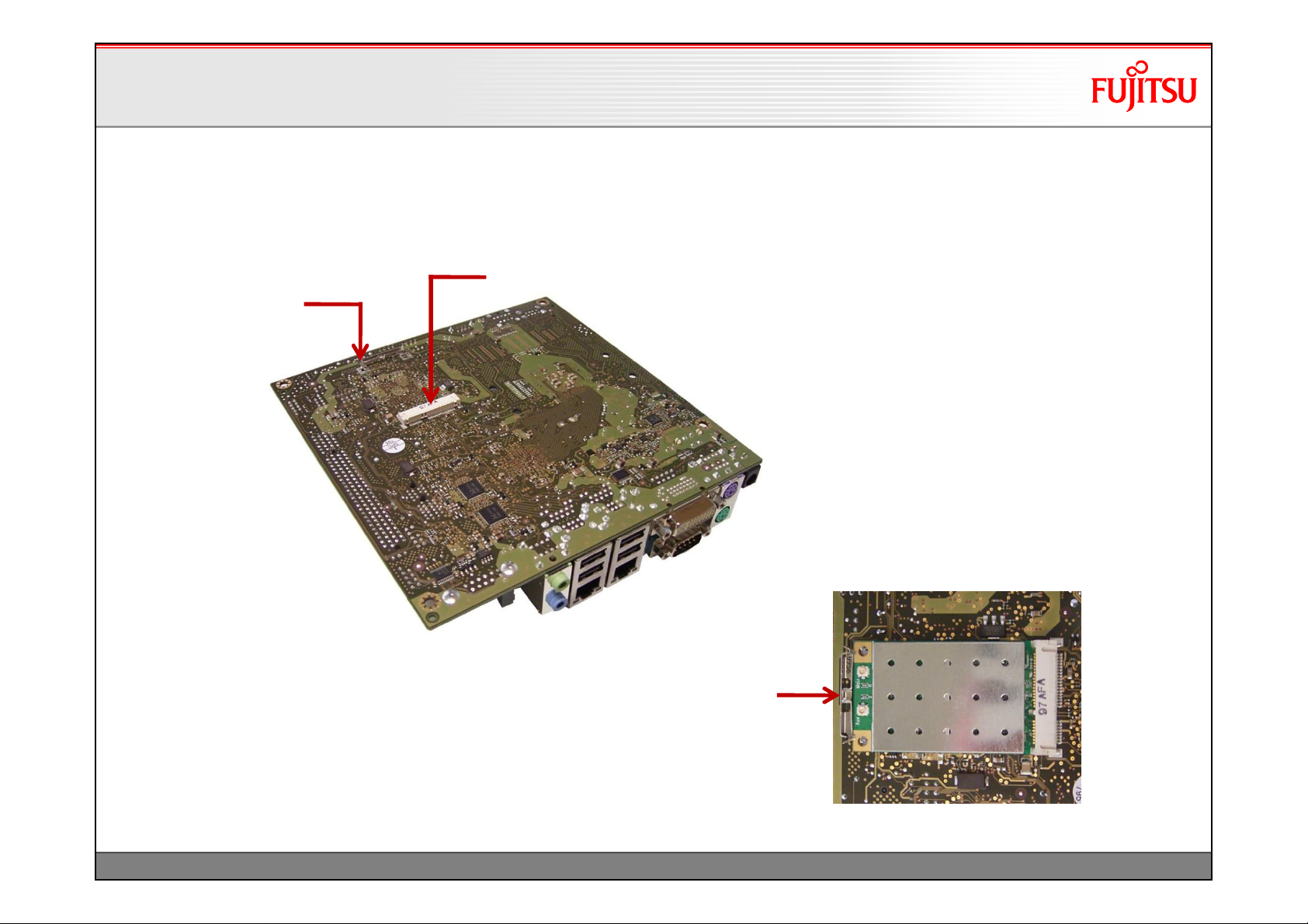
Mini PCI Express Extension Slot (bottomside)
Mini PCI Express Extension Slot (bottomside)
Mini PCI Express Connector (incl. USB support)
MechanicalLock for
Mini PCI Express Card
47
Note:
Mini card lock supports full length
cards only!
TechNotes_D2963_V1.0 Copyright 2010 FUJITSU LIMITED
Page 49

System Monitoring
• Temperature Sensors and Fans
• SystemGuard: Fan/Temperature Monitor
• SilentFanConfig: Customize System Monitoring
• Temperature Reference Points
48
TechNotes_D2963_V1.0 Copyright 2010 FUJITSU LIMITED
Page 50

System Monitoring
System Monitoring
D2963-S: Fans
D2963-S: Fans
FAN 1
(CPU Fan)
FAN 2
(Chassis)
Note: Do not attach more than one fan per connector!
49
TechNotes_D2963_V1.0 Copyright 2010 FUJITSU LIMITED
Note:
Fan1 PWM (4-wire) only!
Fan2: PWM (4-wire) and voltage controlled
(3-wire) possible.
Selectable via BIOS Setup
Page 51

System Monitoring
System Monitoring
D2963-S: Temperature Sensors
D2963-S: Temperature Sensors
CPU Sensor
(inside Processor)
50
Sensor 2
(inside Northbridge)
Sensor 1
(inside Super I/O)
TechNotes_D2963_V1.0 Copyright 2010 FUJITSU LIMITED
Page 52

System Monitoring
System Monitoring
D2963-S: BIOS Fan Settings
D2963-S: BIOS Fan Settings
BIOS Setup option for Fan2
Note: Default setting is PWM (4-Wire)
Setting “3-Wire”:
The default minimum operating voltage
is set to ~ 6V; the maximum operating
voltage (full speed) is 12V.
Note:
If a 3-wire fan is used while BIOS Setup
is set to “4-Wire”, the fan will operate at full
speed (=12V operating voltage)!
51
TechNotes_D2963_V1.0 Copyright 2010 FUJITSU LIMITED
Page 53

System Monitoring
System Monitoring
SystemGuard: Fan/TemperatureMonitor
SystemGuard: Fan/TemperatureMonitor
Windows-based Monitoring Tool
•
•Download link to latest version:
ftp://ftp.ts.fujitsu.com/pub/Mainboard-OEM-Sales/Services/Software&Tools/Common-Mainboard-Tools/SystemGuard/
Note:
Version 3.50 or higher recommended for D2963-S
•SystemGuardoffers several options like “LogFile-feature” and “No Adjustments-mode”
Details are available here:
ftp://ftp.ts.fujitsu.com/pub/Mainboard-OEM-Sales/Services/Software&Tools/Common-Mainboard-Tools/SystemGuard/Documentation/
•
Note: A Windows-based API is available for easy implementation of the
System Monitoring features like fan speed, sensor temperatures etc.
ftp://ftp.ts.fujitsu.com/pub/Mainboard-OEM-Sales/Products/Mainboards/Industrial&ExtendedLifetime/D2963-S/IndustrialTools_D2963-
S/BMC_Management-Controller-API/
52
TechNotes_D2963_V1.0 Copyright 2010 FUJITSU LIMITED
Page 54

System Monitoring
System Monitoring
D2963-S: SystemGuard
D2963-S: SystemGuard
Temperature Sensors
Northbridge Sensor
Super I/O Sensor
Processor Sensor
Sensor / Fan Matrix
Factory default setting:
- FAN1 (CPU) controlled by
Processor temperature
- FAN2 controlled by all sensors
1)
Current Fan Speed
1) Note: Characteristics for FAN1 is
always dependent on CPU
temperature –fully controlled by the
system BIOS. Due to safety
reasons this influence cannot be
disabled!
All relevant System Monitoring parameters can be
customized via SilentFanConfig-Tool!
53
TechNotes_D2963_V1.0 Copyright 2010 FUJITSU LIMITED
Page 55

System Monitoring
System Monitoring
SystemGuard–Sample forCustomizedFan Settings
SystemGuard–Sample forCustomizedFan Settings
Temperature Range for Sens1 adjusted
Minimum fan speed within “green” range;
fan speed increases within “blue” range
Sensor / Fan Matrix
Only Sensor 1 (Super I/O) controls Fan2
Current Fan Speed
Min. fan speed (fan2) reduced
Note: This specific setting is recommended if
D2963-S is installed in the Fujitsu Industrial MiniITX Chassis.
Download link for this setting:
ftp://ftp.ts.fujitsu.com/pub/Mainboard-OEMSales/Products/Accessories/Industrial-Mini-ITXChassis/Adjusted_Fan_Setting_D2963-S/
All relevant System Monitoring parameters can be
customized via SilentFanConfig-Tool!
54
TechNotes_D2963_V1.0 Copyright 2010 FUJITSU LIMITED
Page 56

System Monitoring
System Monitoring
SilentFanConfig: Customize System Monitoring
SilentFanConfig: Customize System Monitoring
Windows-based Configuration Tool
•
ftp://ftp.ts.fujitsu.com/pub/Mainboard-OEM-Sales/Products/Mainboards/Industrial&ExtendedLifetime/D2963S/IndustrialTools_D2963-S/SilentFanConfigManager/
•Use SilentFanConfigto adjust the required settings.
•As result, SilentFanConfigcreates a BIOS configuration file.
Save file as "smco.in“
•Afterwards you have to use the DOS-tool "SMCO" to flash the
new fan settings into the BIOS.
•Copy smco.exe and smco.into the DOS boot medium (USB-stick
or USB-floppy or harddiskwith DOS), boot on target platform and
run following operation: smcosmco.in
•New settings are written permanently to system BIOS
Note: SilentFanConfigV1.6 or higher required for D2963-S
55
TechNotes_D2963_V1.0 Copyright 2010 FUJITSU LIMITED
Page 57

System Monitoring
System Monitoring
D2963-S: SilentFanConfig(1)
D2963-S: SilentFanConfig(1)
Basic Fan Settings
Adjust minimum fan
startup speed
Enable/disable fan
speed control
56
TechNotes_D2963_V1.0 Copyright 2010 FUJITSU LIMITED
Page 58

System Monitoring
System Monitoring
D2963-S: SilentFanConfig(2)
D2963-S: SilentFanConfig(2)
Basic Sensor Settings
Adjust related temperature settings
57
TechNotes_D2963_V1.0 Copyright 2010 FUJITSU LIMITED
Page 59

System Monitoring
System Monitoring
D2963-S: SilentFanConfig(3)
D2963-S: SilentFanConfig(3)
Global Settings
Adjust minimum fan speed
(Condition for “Fan removed”)
Adjust sensor / fan influence
Note: Due to safety reasons the
CPU sensor always influences
Fan 1 (CPU)!
58
TechNotes_D2963_V1.0 Copyright 2010 FUJITSU LIMITED
Page 60

System Monitoring
System Monitoring
D2963-S: SilentFanConfig(4)
D2963-S: SilentFanConfig(4)
Import/Export Settings
Create configuration file “smco.in”
for additional SMCO flash tool (DOS-based).
Customized System Monitoring settings
can be flashed permanently to system BIOS.
59
TechNotes_D2963_V1.0 Copyright 2010 FUJITSU LIMITED
Page 61

System Monitoring
System Monitoring
ThermographyD2963-S
ThermographyD2963-S
60
TechNotes_D2963_V1.0 Copyright 2010 FUJITSU LIMITED
Page 62

System Monitoring
System Monitoring
ThermographyD2963-S (Front)
ThermographyD2963-S (Front)
61
TechNotes_D2963_V1.0 Copyright 2010 FUJITSU LIMITED
Page 63

System Monitoring
System Monitoring
ThermographyD2963-S (Rear)
ThermographyD2963-S (Rear)
62
TechNotes_D2963_V1.0 Copyright 2010 FUJITSU LIMITED
Page 64

System Monitoring
System Monitoring
Climatic chamber test D2963-S
Climatic chamber test D2963-S
D2963-S withthermocouplesforall criticalcomponents
63
TechNotes_D2963_V1.0 Copyright 2010 FUJITSU LIMITED
Page 65

System Monitoring
System Monitoring
Temperature Reference Points
Temperature Reference Points
Operating Conditions:
Circulating air max. 60°C
Usage 24h / 7 days
Inductors max. 90°C
Inductors max. 90°C
Northbridge Heatsink
max. 75°C
Crystal max. 75°C
Clock Synth.max. 85°C
Audio Codec max. 75°C
Super I/O max. 75°C
All Capacitors:
max. 75°C
Voltage Regulators
max. 90°C
Inductor / Voltage Regulator
max. 90°C
Southbridge Heatsink
max. 80°C
Battery max. 60/70°C
1) Note: Battery operation is
specified in temperature range up
to 60°C. Operation between
60°C and 70°C may result in:
-Higher self discharge rate
-Decline of specified characteristics
-Danger of leakage increases
1)
Reference Point Limit Temperatures (Component Surface) must not be exceeded!
64
TechNotes_D2963_V1.0 Copyright 2010 FUJITSU LIMITED
Page 66

System Monitoring
System Monitoring
Temperature Reference Points
Temperature Reference Points
Operating Conditions:
Circulating air max. 60°C
Usage 24h / 7 days
Crystal max. 75°C
Voltage Regulator
max. 90°C
Voltage Regulator
max. 90°C
Crystal max. 75°C
LAN Controller
max. 80°C
COM Driver
max. 90°C
Reference Point Limit Temperatures (Component Surface) must not be exceeded!
65
TechNotes_D2963_V1.0 Copyright 2010 FUJITSU LIMITED
Page 67

System Monitoring
System Monitoring
Processor Excess Temperature Protection
Processor Excess Temperature Protection
If the processor temperature exceeds the internal Alert temperature level (~ 100°C; exact level depends
on processor), the onboard electronics forces the processor to throttle down (“ProcHot”) in order to
reduce the power consumption and prevent the system from damage. The processor performance will
be reduced to ~ 50%.
Note: This performance compensation will not be reset automatically after the processor has reached its
specified temperature range again, but will remain active until the system is shut down or set to S3 (Standby) or
S4 (save to disk).
Due to reliability reasons this option is <Enabled> in BIOS Setup by default.
If this option is disabled, the system will shutdown in case of excess processor temperaturwhen
reaching a limit of ~ 125°C
66
TechNotes_D2963_V1.0 Copyright 2010 FUJITSU LIMITED
Page 68

Mainboard Power Consumption
• AC Mains Power Consumption
67
TechNotes_D2963_V1.0 Copyright 2010 FUJITSU LIMITED
Page 69

Mainboard Power Consumption
Mainboard Power Consumption
AC Mains Power Consumption
AC Mains Power Consumption
D2963-S1
Sempron200U, 1GHz single / max. 8W
1GB RAM, HDD 2.5” SATA, Win XP
AC adapter E557-V55 @230V
Pure MS-DOS
Windows XP “Idle” ~ 15W ~ 16W
Windows XP Full Load
Windows XP „S3“ („Standby“)
Windows Shutdown„S5“
1)Boot fromUSB stick
2)Windows XP, 100% processorload(AMD stress tool)
3)Dependson power supply efficiency @ minimum output power, BIOS settings and LAN configuration
1)
2)
3)
3)
~ 23W ~ 30W
~ 20W ~ 33W
< 1W < 1W
< 1W < 1W
AthlonL325, 1.5GHz dual / max. 18W
1GB RAM, HDD 2.5” SATA, Win XP
AC adapter E557-V55 @230V
D2963-S2
68
TechNotes_D2963_V1.0 Copyright 2010 FUJITSU LIMITED
Page 70

Special Features
•Mainboard Watchdog
•Harddisk Security
69
TechNotes_D2963_V1.0 Copyright 2010 FUJITSU LIMITED
Page 71

Special Features
Special Features
Mainboard Watchdog
Mainboard Watchdog
•
Watchdog feature provides secure system behaviourin case
of software crash
•System shuts down or
•System reboots
Example:
Printer Server (unattended)
-Specific SW application re-triggers watchdog
timer every 10 seconds
-Iftheprintersoftwarehangs, there-trigger
applicationwill nolongerbeactive, and the
watchdogforcesthesystemtoreboot
-After reboot, printersoftwareisavailableagain
Note: DetailedprogramminginfoabouttheWatchdogfeature
isavailablein theOEM mainboard specification.
A Windows-based API is available for easy implementation of the
GPIO features (included in SystemMonitoringAPI)
ftp://ftp.ts.fujitsu.com/pub/Mainboard-OEM-Sales/Products/Mainboards/Industrial&ExtendedLifetime/D2963-
S/IndustrialTools_D2963-S/BMC_Management-Controller-API/
70
TechNotes_D2963_V1.0 Copyright 2010 FUJITSU LIMITED
(Demo Application)
Page 72

Special Features
Special Features
Harddisk Security
Harddisk Security
•
Password Protection for Harddisk
•Password Entry on each Boot or
•Silent Boot from Protected Harddisk
à
Second option useful for unattended system
to ensure OS boot w/o any user interaction
Note: Harddisk protected by HDD password cannot
be used any more if password gets lost.
Keeps your SW IP secure within your system!
Silent Boot -Option
71
TechNotes_D2963_V1.0 Copyright 2010 FUJITSU LIMITED
Page 73

Operating System Support
•Windows ® XP / VISTA / Windows 7
•Windows® XP Embedded
•Linux / Embedded Linux
72
TechNotes_D2963_V1.0 Copyright 2010 FUJITSU LIMITED
Page 74

Operating System Support
Operating System Support
Support for Windows® XP / VISTA / Windows 7
Support for Windows® XP / VISTA / Windows 7
•
Mainboard D2963-S is designed according to the
Microsoft Guidelines for Windows XP,
Windows VISTA and Windows 7
• MS certified drivers are available via OEM DU-DVD,
OEM FTP Server and FTS Website
73
TechNotes_D2963_V1.0 Copyright 2010 FUJITSU LIMITED
Page 75

Operating System Support
Operating System Support
Supportfor Windows® XP Embedded
Supportfor Windows® XP Embedded
•
Conditions
•Customer is familiar with XP Embedded & Target Designer / Component Designer
•Customer creates specific XP Embedded SW installation at his own responsibility & risk
•
FTS provides Board Support Package
(SLD files incl. drivers for D2963-S onboard components)
•Drivers contain englishlanguage version
•SLD files have no license restrictions
•Complete BSP will be available for download:
ftp://ftp.ts.fujitsu.com/pub/Mainboard-OEM-Sales/Products/Mainboards/Industrial&ExtendedLifetime/D2963-S/Drivers_D2963-S/
74
TechNotes_D2963_V1.0 Copyright 2010 FUJITSU LIMITED
Page 76

1)OK 3)OK 3)OK 3)
1)OK 3)OK 3)OK 3)
1)
1)
3)OK 3)OK 3)
3)OK 3)OK 3)
2)
2)
3)OK 3)OK 3)
3)OK 3)OK 3)
Debian Etch, 32 Bit (netinst)
Debian Etch, 64 Bit (netinst)
Debian Lenny, 32 Bit (netinst)
Debian Lenny, 64 Bit (netinst)
3)OK 3)OK 3)
3)OK 3)OK 3)
Ubuntu 8.10, 32 Bit
Ubuntu 8.10, 32 Bit
Operating System Support
Operating System Support
SupportforLinux OS (preliminary)
SupportforLinux OS (preliminary)
openSUSE 10.3, 32 Bit
openSUSE 10.3, 64 Bit
openSUSE 11.0, 32 Bit
openSUSE 11.0, 64 Bit
SUSE Linux Enterprise 10 SP2, 32 Bit
SUSE Linux Enterprise 10 SP2, 64 Bit
Fedora 9, 32 Bit
Fedora 9, 64 Bit
Red Hat Enterprise Linux 5.2, 32 Bit
Red Hat Enterprise Linux 5.2, 64 Bit
Ubuntu 7.1, 32 Bit
Ubuntu 7.1, 64 Bit
Basic OS
Installation
OK OK
OK OK
OK OK
OK OK
OK OK OK
OK OK OK
OK OK
OK OK
OK OK OK
OK OK OK
Failed Failed Not testable Failed Failed Not testable
Failed Failed Not testable Failed Failed Not testable
OK OK OK OK OK OK
OK OK OK OK OK OK
OK OK OK
OK OK OK
OK OK OK OK OK OK
OK OK OK OK OK OK
HDD / DVD
Read/Write
Access
Graphics LAN
OK
OK
OK
OK
OK
OK
OK OK OK
OK OK OK
OK
OK
OK OK OK
OK OK OK
OK
OK
OK
OK
2nd LAN
Sound
1) See installation hints: http://www.suse.de/~sndirsch/ati-installer-HOWTO.html
2) Only preinstalled ATI driver, driver kit provided via ati.amd.com isn't working
3) Tested with compiled kernel 2.6.27.5
Note: Note: If standard kernel is used, LAN cable must not be connected before LAN module is loaded
4) Note “Debian Etch”: No official support for Debian by AMD/ATI, but working installation is possible
-After basic installation, system shows several boot errors (= Kernel 2.6.18-5-486)
-Run Debian updater (Kernel update) to resolve boot errrors (= Kernel 2.6.18-6-486)
-Install ATI graphics driver http://ati.amd.com/support/driver.html
("Linux x86 -> Integrated/Motherboard -> Radeon Xpress 1250“)
75
TechNotes_D2963_V1.0 Copyright 2010 FUJITSU LIMITED
Unofficial Wiki for ATI
Linux Drivers
http://wiki.cchtml.com/index.
php/Main_Page
Page 77

Operating System Support
Operating System Support
SupportforEmbedded Linux (preliminary)
SupportforEmbedded Linux (preliminary)
• FTS provides free demo BSP for Embedded Linux
•Download link
ftp://ftp.ts.fujitsu.com/pub/Mainboard-OEM-Sales/Products/Mainboards/Industrial&ExtendedLifetime/D2963-S/Drivers_D2963-S/
76
TechNotes_D2963_V1.0 Copyright 2010 FUJITSU LIMITED
Page 78

77
TechNotes_D2963_V1.0 Copyright 2010 FUJITSU LIMITED
 Loading...