

Page 1

BIOS Handbook D2840/D2841
Description
Page 2

Are there ...
... any technical problems or other questions you need clarified?
Contact:
•ourHelpDesk
• your sales partner
• your sales outlet
The latest information on our products, tips, updates, etc., can be found
on the Internet under: "
Help Desk list on the internet: "http://ts.fujitsu.com/helpdesk"
http://ts.fujitsu.com"
Page 3

Page 4

Published by
Fujitsu Technology Solutions GmbH
A26361-D2840-Z220-1-7619, Edition 1
2009/04
Produced by
XEROX Global Services
Page 5

BIOS manual D2840/D2841
Description
Introduction 1
Navigating BIOS Setup
Main Menu – System
Advanced Menu – Advanced system
configuration
Security Menu
Power Menu – Energy saving functions
Boot Menu – System boot
Exit Menu
Flash-BIOS update
Index
- Security features
– Exit BIOS Setup
functions
3
6
13
25
30
33
34
35
39
Page 6

Intel and Pentium are registered trademarks and MMX and OverDrive are
trademarks of Intel Corporation, USA.
Microsoft, MS, MS-DOS and Windows are registered trademarks of Microsoft Corporation.
Examples of Windows operating systems: Windows 95, Windows 98, Windows Me,
Windows NT, Windows 2000, Windows XP, Windows Vista.
PS/2 and OS/2 Warp are registered trademarks of International Business Machines, Inc.
All other trademarks referenced are trademarks or registered trademarks of their
respective owners, whose protected rights are acknowledged.
Copyright © Fujitsu Technology Solutions GmbH 2009
All rights reserved, including rights of translation, reproduction by printing, copying
or similar methods, in part or in whole.
In the event of violations, perpetrators will be liable to prosecution for damages.
All rights reserved, including rights created by patent grant or registration of a utility model or design.
Subject to availability and technical modifications.
Page 7

Contents
Contents
Introduction ........................................................................... 1
Notational conventions .................................................................. 2
Navigating BIOS Setup ................................................................. 3
Open BIOS Setup ....................................................................... 3
If you w ant to open the "Bo
BIOSSetupwithincorrec
Navigating BIOSSetup .................................................................. 5
ExitingBIOS Setup ..................................................................... 5
Main Menu –Systemfunctions ......................................................... 6
System Date/System Time .............................................................. 6
Diskette A- diskettedrive ................................................................ 6
SATA port .............................................................................. 7
TotalSectors ........................................................................ 7
Maximum Capacity– Hard disk capacity . .. ............................................ 8
Multi–sector Transfers ............................................................... 8
LBAMode Control ................................................................... 9
32 BitI/O -Bus width fordatatransfer ................................................ 9
Transfermode ...................................................................... 9
Ultra DMA Mode – Transfer Speed ................................................... 9
SMARTMonitoring .................................................................. 9
Firmware ........................................................................... 10
Silent Mode– Noise level forharddisksandopticaldrive ............................... 10
Password Status– Display harddisk password status .................................. 10
Change Password . .................................................................. 11
Hard Disk MasterPassword .......................................................... 11
HD-ID .............................................................................. 11
Boot Features – System boot . ........................................................... 11
POST Errors – Aborting system boot . . . . . ............................................. 11
Fast Boot– Quick Self-test ........................................................... 12
POST Diagnostic Screen – POST information or Boot Logo ............................. 12
Boot Menu – System boot ........................................................... 12
System Memory –Workingmemory ...................................................... 12
Extended Memory ...................................................................... 12
Advance
Periphe
Adva
d Menu – Advanced system configuration .....................................
ral configuration– Portsand controllers ............................................
/Serial2 –Serialports ........................................................
Serial 1
el port (system-depe ndent) . . ...................................................
Parall
el Mode -Parallel data transfer ..................................................
Parall
yDisk Controller ...............................................................
Flopp
st Controller .................................................................
USB Ho
Controller .....................................................................
Audio
ontroller ......................................................................
LAN c
emote Boot – Load operating system via LAN . . .. . . .............................
LAN R
nced System Configuration .........................................................
lay,primary .....................................................................
Disp
–Device 2 .....................................................................
IGD
–Device 2, Function1 ..........................................................
IGD
MT 5.0mode ....................................................................
DV
ot Menu" immediately: . . ....................................
tsettings .......................................................
13
13
14
14
14
14
14
15
15
16
16
16
17
17
17
3
4
A26361-D2840-Z220-1-7619, edition 1
Page 8

Contents
IGDMemory Size ................................................................... 18
High PrecisionEvent Timer .......................................................... 18
SMARTDevice Monitoring ........................................................... 18
FanControl–Fan speed ............................................................ 18
SATA0Compatible Mode ............................................................ 18
Advanced ProcessorOptions ............................................................ 19
Enhanced SpeedStep . . . ............................................................ 19
Enhanced IdlePower State .......................................................... 19
CPU Thermal Management . . ........................................................ 20
Virtualization Technology (VT-x) . . . . . ................................................. 20
NX Memory Protection ............................................................... 20
Adjacent CacheLinePrefetch ........................................................ 20
Hardware Prefetch .................................................................. 21
Hyper-threading . . . . . ................................................................ 21
LimitCPUIDFunctions .............................................................. 21
Core Multi-Processing ............................................................... 21
PCI Configuration ....................................................................... 22
DMI Event Logging . . . . . . ................................................................ 23
Eventlogvalidity .................................................................... 23
Event log capacity . . . ................................................................ 23
View DMIevent log .................................................................. 23
EventLogging ...................................................................... 23
Mark DMIeventsas read ............................................................ 24
ClearallDMIeventlogs ............................................................. 24
Security Menu - Securityfeatures ...................................................... 25
Assigningandcancelling passwords ..................................................... 25
Supervisor Password ................................................................ 25
User Password ...................................................................... 25
SetSupervisor Password ............................................................ 26
SetupPassword Lock ............................................................... 26
SetUserPassword .................................................................. 26
User Password Mode–effectsoftheuserpassword ................................... 26
Password On Boot .................................................................. 26
SetupPassword Lock ............................................................... 27
SetSupervisor /UserPassword ..................................................... 27
Cancelling supervisor/user password ................................................. 28
Setupprompt ........................................................................... 28
VirusWarning .......................................................................... 28
ATAVulnerability Protection .............................................................. 29
Diskette Write – Write protection for floppydiskdrive ....................................... 29
FlashWrite– System BIOSwriteprotection .............................................. 29
Power Menu – Energy saving functions . . . ............................................. 30
Power On S ource – Management of switch-on sources . . .................................. 30
PowerOnSource: LAN –Switchon viaLAN controller ................................ 30
PowerOnSource: Wake Up Timer–Switchonaccording to time ....................... 31
PowerFailureRecovery –Systemstatus after apower failure .............................. 31
USBAtPower Off ....................................................................... 32
USBKeyboard ...................................................................... 32
Boot Menu –Systemboot .............................................................. 33
Boot PriorityOrder ..................................................................... 33
Excluded from Boot Order . . . ............................................................ 33
A26361-D2840-Z220-1-7619, edition 1
Page 9

Contents
Exit Menu –ExitBIOSSetup .......................................................... 34
Save Changes & Exit . . .................................................................. 34
Discard Changes & Exit . . . . . . ........................................................... 34
Get Default Values – Restoring standard (default) settings . . . . . ............................. 34
Load PreviousValues –Restoringprevious settings ....................................... 34
Flash-BIOS update ..................................................................... 35
Error message after a Flash-BIOS update . . . . . ............................................ 37
FlashMemory Recovery Mode ........................................................... 38
DeskFlash .............................................................................. 38
Index .................................................................................. 39
A26361-D2840-Z220-1-7619, edition 1
Page 10

Contents
A26361-D2840-Z220-1-7619, edition 1
Page 11

Introduction
Introduction
BIOS Setup provides settings for system functions and the hardware co n fig uration for the device.
Any changes you make take effect as soon as you save t he settings and quit BIOS Setup.
The individual menus in BIOS Setup p rovide settings for the following areas:
Main:
Advanced:
Security:
Power:
Boot
Exit:
System functions
Advanced system configuration
Security functions
Energy saving function
Configuration of the start-up sequence
Save and quit
The individual menus and setting options are described in alphabetical
order in the following chapters.
The setting options depend on the hardware configuration of your device.
Some menus and certain settings may therefore not be available in BIOS Setup on your
device, or the menus may be in a different place, depending on the BIOS revision.
A26361-D2840-Z220-1-7619, edition 1 1
Page 12

Introduction
Notational conventions
Pay particular attention to text marked with this symbol. Failure to observe
these warnings could pose a risk to health, damage the device or lead
to loss of data. The warranty will be invalidated if the device becomes
defective through failure to take notice of this warning.
Indicates important informat
ion for the proper use of the device.
►
This font
This font
This font
"This font"
Abc
This font Indicates a default value in the BIOS menu settings (e.g. Enabled)
Indicates an activity that must be performed in the order shown
Indicates the result of an action
Indicates data entered usin
command line, e.g. your pass
start a program (start.ex
Indicates information that is displayed on the screen by a program, e.g.:
Installation is complete!
Indicates
• terms and text used in a software interface, e.g.: Click Save
• names of programs or files, e.g. Windows or setup.exe
Indicates
• Cross-references to another section, e.g. "Safety information"
• Cross-references to an external source, e.g. a web address: For more
information, go to
• Names of CDs, DVDs and titles or designations for other materials,
e.g.: " CD/DVD Drivers & Utilities" or "Safety" manual
Indicates a key on the keyboard, e.g:
g the keyb oard in a program dialogue or
word ((Name123) or a command used to
e)
"http://ts.fujitsu.com"
F10
2 A26361-D2840-Z220-1-7619, edition 1
Page 13

Navigating BIOS Setup
Navigating BIOS Setup
Open BIOS Setup
► Restart the device by switching off and on.
BIOSSetupSetup,BIOS-Setup
Wait until the screen output appear
► Press function key
► If you have assigned a supervisor p
password and confirm it with the Ent
The BIOS Setup Main menu will be displayed on the screen.
► Press function key
The BIOS release information will be displayed:
• BIOS Setup version (e.g. 6.0)
• BIOS Setu p revision (e.g. Rev. 1.03.2451)
The final digits refer to the number o
With the aid of the mainboard number you can locate the correct technical
manual for the mainboard on the "Drivers & Utilities" or "ServerStart" CD/DVD.
Alternatively you can also use it to download the corresponding BIOS update file
from the Internet (see "
F2
.
F1
.
Flash-BIOS update", Page 35).
If you want to open the "Boot Menu" immediately:
You can use this function if you do not want to boot the system from the drive
specified as the first device in the Boot Priority O rder in the Boot menu.
s.
assword, you must now enter this
er key.
f the mainboard.
► Press the function key
BootMenuF12,functionkey
The Boot Menu is displayed as a popup window on the screen. You can now select the
drive from w hich you wish to boot the operating system. The selection options are the
same as the possible settings in the Boot Priority Order in the Boot menu. Your selection
is only valid for the current system boot. The settings specified in the Boot Priority Order
in the Boot menu will be applied again the next time the system is started.
► Use the
boot the system on this occasion and press Enter.
► To open BIOS Setup, use the
entry and press En ter to confirm the selection.
A26361-D2840-Z220-1-7619, edition 1 3
and cursor keys to select which drive you want to use to
If the drive is marked with an "!" symbol then it cannot be selected as a boot drive. You
can check why this drive is not available for booting in the BIOS Setup (in the Boot menu).
F12
.
and cursor keys to select the Setup
Page 14
Navigating BIOS Setup
BIOS Setup with incorrect settings
Systemboot
If an incorrect setting in BIOS Setup prevents the system booting and the system cannot
be booted three times in a row, the default BIOS Setup settings will be applied once,
the next time the system is booted. The following error message will appear:
Previous boot incomplete - Default configuration used
F2
Pressing the
key allows you to check and correct the settings in BIOS Setup.
Any incorrect BIOS Setup settings that prevented the system from booting can now
be corrected. This will allow the system to boot without error again.
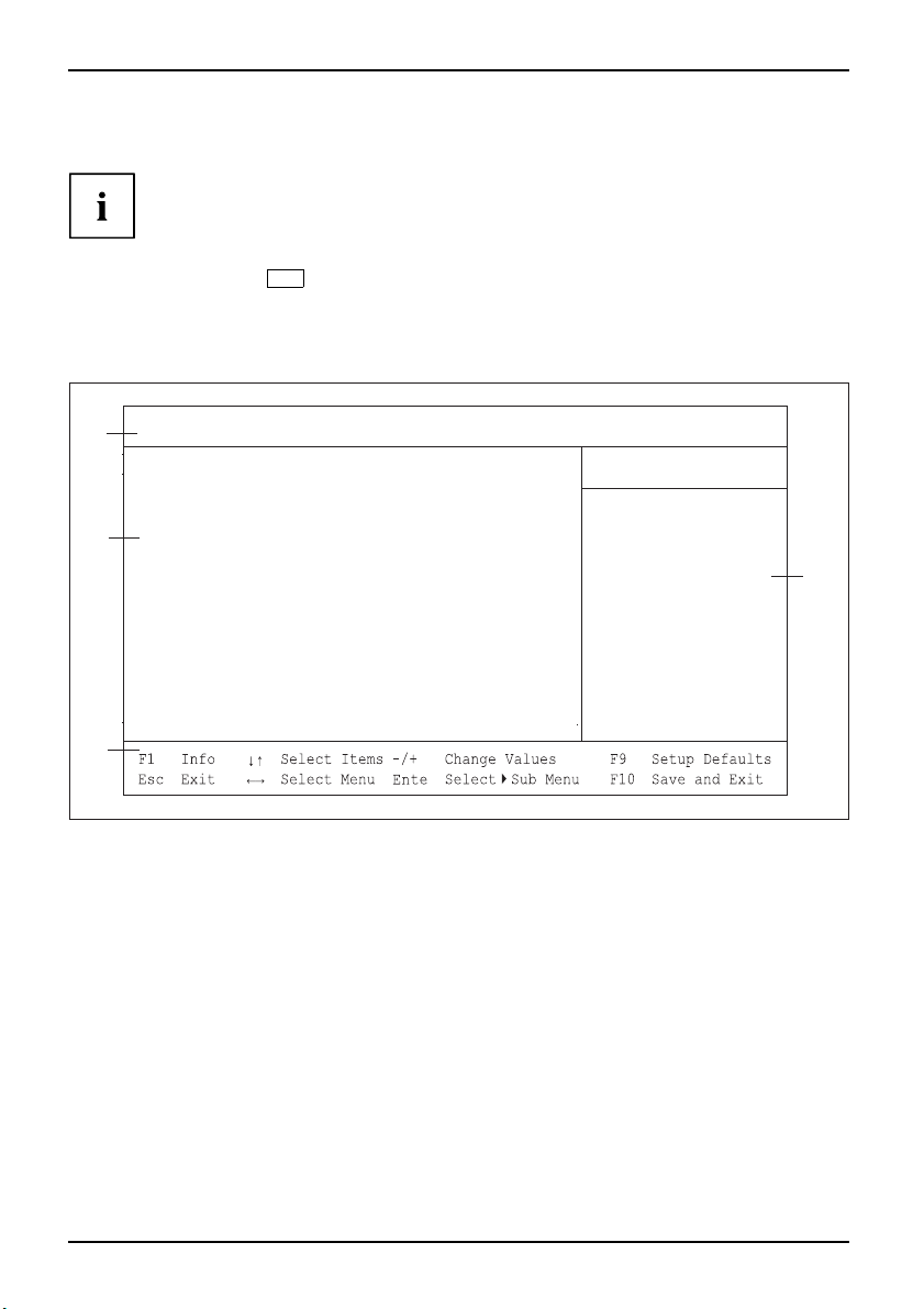
Example Main menu of the BIOS S
Advanced Security Power Boot
1
2
4
Main
System Time: [10:52:28]
System Date:
Diskette A:
SATA Port 0
SATA Port 1 [HL-DT-ST DVDRAM GH10N-(S1)]
SATA Port 2 None
SATA Port 3 None
Boot Features
System Memory: 633K
Extended Memory:
etup
[12/11/2008 ]
None
None
1980 M
Exit
Item Specific Help
<Tab>, <Shift-Tab>, or
<Enter> selects field
r
1 = Menu bar
2 = Working area
3 = Help area
4 = Operations bar
The BIOS Setup screen is divided into the following areas:
Menu bar
(1):
The menu
bar is used to sele ct the different BIOS Setup menus.
Working area ( 2): The working area displays the setting options (fields) for the selected menu.
You can set the entries in th e displayed fields according to y our requirements.
► I ndicates fields that open further submenus. You can change entries
in these submenus.
* Indica tes configuration conflicts that must be resolved to ensure t hat the
device functions correctly.
Help area (3): Brief information on the selected field is displayed in the help area.
SSetup
BIO
Operations bar (4): The operations bar lists the keys available fo r use with BIOS Setup.
3
4 A26361-D2840-Z220-1-7619, edition 1
Page 15

Navigating BIOS Setup
You can display additional information (e.g. BIOS version) by
pressing the
F1,functionkeyBIOSversion
F1
function key.
Navigating BIOS Setup
BIOSSetup
or cursor keys
or cursor keys
Enter
+
F9
F7
ESC
or
or-keys (numeric keypad) Change entry for field
function key Set d efault entries for all men
function key
Select menu from menu bar
Select field - selected field is hi
Open submenu (marked with Ê)
ESC
Reset entries that were in use w
Exiting BIOS Setup
► To exi t BIOS Setup, select the Exit menu from the menu bar.
You can then decide whether y
► Select the required option.
► Press the Enter key.
ou want to save th e changed settings.
ghlighted
Enter
, close submenu
us
hen BIOS Setup was opened.
A26361-D2840-Z220-1-7619, edition 1 5
Page 16

Main Menu – System functions
Main Menu – System functions
MainMenuBIOSSetup
Main
System Time: [10:52:28]
System Date:
Diskette A:
SATA Port 0
SATA Port 1 [HL-DT-ST DVDRAM GH10N-(S1)]
SATA Port 2 None
SATA Port 3 None
Boot Features
System Memory: 63
Extended Memory:
Example showing the Ma
in menu
[12/11/2008 ]
None
None
3
K
1980M
Item Specific Help
<Tab>, <Shift-Tab>, or
<Enter> selects field.
System Date/System Time
DateTime
Displays the current date/time set on the device. The date is shown in the format "mm/dd/yyyy".
The time is shown in the format "hours:minutes:seconds". Enter the new date/time in the
System Date/System Time fields respectively to change the current date/time settings. Use the
tab key to move the cursor between the System Time and System D ate fields.
If the settings in the System Time and System D ate fields are frequently
wrong when you power up the computer this means the lithium battery is
not providing power. Replace the lithium battery.
Refer to the mainboard manual for information on how to replace the lithium battery.
Diskette A - diskette drive
This field is used to specify the type of diskette drive installed.
360K, 720K, 1.2M, 1.4M,
2.8M
None there is no diskette drive installed.
6 A26361-D2840-Z220-1-7619, edition 1
The entry depends on the diskette drive installed.
Page 17

Main Menu – System functions
SATA port
Open the Submenu that provides settings for the corresponding hard disk drive.
The manufacturer’s designation for the drive is shown next to each submenu.
The following menu items cannot be changed.
SATA Port 1
Total Sectors 156301488
Maximum Capacity 80 GByte
[HL-DT-ST DVDRAM GH10N-(S1)]
Multi-Sector Transfers: [Disabled]
LBA Mode Control:
32 Bit I/O: [Enabled]
Transfer Mode: [FPIO 4 / DMA 2]
[Enabled]
Ultra DMA Mode: [Mode 5]
Smart Monitoring: Disabled
Firmware: EV03
Silent Mode: [Medium]
Password Status: Not installed
Change Password: [Press Enter]
Total Sectors
Displays the number of sectors on the h ard disk.
Not for optical storage media.
Item Specific Help
Configure automatic
acoustic management for
the drive. Changes will
take effect immediately.
[Disabled]
Maximum performance
No acoustic management
[Medium]
Intermediate level of
acoustic management
[Silent]
Maximum level of
acoustic management
A26361-D2840-Z220-1-7619, edition 1 7
Page 18

Main Menu – System functions
Maximum Capacity– Hard disk capa city
HarddiskparametersHarddiskcapacity
Shows the capacity of the hard disk as an LBA va lue. The LBA value is the capacity calculated by the
BIOS based on the maximum possible number of sectors reported by the hard disk. IDE and BIOS
restrict the arrangement of hard disks into cylinders, heads and sectors through maximum permissible
values. The hard disk permits more cylinders but fewer heads than the BIOS. A combination of IDE
and BIOS restrictions leads to a maximum addressable storage area of 528 MByte.
Not for optical storage media.
The following table lists the maximum permissible values and the resulting
maximum usable memory capacities.
BIOS
Max. sectors per
head (at 512 Byte)
Max. heads per
cylinder
Max. cylinders 1024 65535 1024 65535
Capacity 8.4 GByte 137 GByte
LBA Translation converts the physical arrangement of a hard disk into cylinders, heads
and sectors so that the logical values generated lie within the above BIOS limitations. This
means that a hard disk capacity of over 528 MByte can be used. The operating system
and application programmes make use of these logical hard disk values. Hard disks of over
528 MByte are configured and operated using LBA mode. If the hard disk sup ports the LBA
mode, then the full memory capacity of the hard disk can be used.
The BIOS also supports 48-bit addressing for hard disks. This industry standard sp eci fies hard disk
capacities up to 144 PByte (Petabyte) - approximately 120,000 times the 137 GByte limit.
63 255 63 65535
256 16 16 65535
IDE
Combination
BIOS/IDE
528 MByte 144 PByte
BIOS 48-bit LBA
Multi–sector Transfers
Shows the number of sec
Disabled
2sectors
4sectors
8sectors
16 sectors
8 A26361-D2840-Z220-1-7619, edition 1
tors per block that can be recognised automatically by the BIOS.
Page 19

Main Menu – System functions
LBA Mode Control
Sets addressing to use consecutive sector numbers (LBA = Logical Block Addressing).
Enabled
Disabled
If the hard disk supports LBA mode and it has a capacity of more than 528 MByte,
then the BIOS uses converted hard disk parameters. This allows the disk’s full
capacity to be used.
The BIOS uses the hard disk parameters and supports a maximum capacity of
528 MBytes.
32 Bit I/O - Bus width for data transfer
This field specifies the bus width for data transfer between the processor and the hard disk controller.
Enabled
Disabled
The data transfer is 32 bits in width at the PCI bus. This enhances performance.
The data transfer is 16 bits
in width.
Transfer mode
Specifies the method used to transfer data from the hard disk to the main memory.
Standard
Fast PIO_1
Fast PIO_2
Fast PIO_3
Fast PIO_4
FPIO 3 / DMA 1
FPIO 4 / DMA 2
UltraDMAMode–TransferSpeed
Performance,increasingHarddisk
Specifies that the hard disk drive should use a fast Ultra DMA transfer mode.
Disabled
Mode0, 1, 2,
3, 4, 5,6
The fast Ultra DMA transfer mode is not set.
The fast Ultra DMA transfer
mode is set.
SMART Monitoring
Shows whether SMART (Self Monitoring Analysis Reporting Technology)
monitoring is activated for the hard disk.
Enabled
Disabled
A26361-D2840-Z220-1-7619, edition 1 9
SMART m onitoring is activated.
SMART monitoring is deactivated.
Page 20

Main Menu – System functions
Firmware
Indicates the firmware version number for the hard disk controller.
Silent Mode – Noise level for hard disks and optical drive
OpticaldriveNoise,opticaldrive
Specifies the noise level for the har
by decreasing the speed at which i
Disabled The drive operates at the highest
Medium
Silent
Depending on the drive , the speed
less noise during operation and p
Depending on the drive, the speed
produces less noise during oper
d disk or optical drive. The noise level of the drive is reduced
t rotates. The drive must support this function.
possible speed.
is reduced to a medium level. The drive produces
erformance is slightly reduced.
is reduced to the lowest level. The optical drive
ation and performance is reduced.
Password Status – Display ha
PasswordStatus
Displays the current security status for the hard disk.
Not
Supported
Not
Installed
Installed
Count expired
Locked
DCO (Power
Cycle)
Frozen until
Power off
Change
Password
Hard Disk
Master
Password
The hard disk does not support a password. You cannot assign a password to
this hard disk.
No password has been assigned to this hard disk.
A password has just been assigned to the hard disk.
The maximum number of permissible attempts at entering the password has been
exceeded. Switch off the system and retry.
The hard disk is protected and a passwo rd must be entered to gain access.
DCO (Device Con figu ration Overlays) is blocked. Switch off the syste m and retry.
Restart the system to change the security status of the hard disk. Open BIOS Setup
during system boot and change the desired settings.
The hard disk password protects you against unauthorised access to your hard
disk drives. Only people w ho know the hard disk password can boot the operating
system from the hard disk or access data on it. The password m ust be four to eight
characters in length. All alphanume rical characters can be used, but no distinction
is made be tween upper-case and lower-case. Passwords are not displayed
during entry. The settings become effective immediately and will remain effective,
regardless of the method used to exit BIOS Setup later. The status of the hard disk
password will be displayed according to the current settings (Installed/Not Installed).
Access to the hard disk is also protected by requiring a master password to be
entered. This is intended for use in situations where the standard password has
been forgotten or is not known. The master password is normally kept secret and
can be obtained by contact ing Fujitsu Technology Solutions customer service. The
master password can be deactivated so that access to the hard disk is only possible
using the standard password.
rd disk password status
10 A26361-D2840-Z220-1-7619, edition 1
Page 21

Main Menu – System functions
Change Pass word
The hard disk password enables you to prevent un authorized access to your hard disk drives.
Booting the operating system of the hard disk or access to data on the hard disk can only be
carried out by people who know the hard disk password. The password must consist of four
to e ight characters. All alphanumerical characters can be used, and the password is not case
sensitive. When entering the password, the password itself is not displayed. The settings become
effective immediately and remain effective regardless of how you end the BIOS Setup later.
The status of the hard disk password is displayed as per the current setting.
Hard Disk Master Pa ssword
Access to the hard disk is al
for example, if the standar
the master password must be
Technology Solutions Se
totheharddiskisonlypo
so granted by entering the master password. This is useful,
d password has been forgotten or is not known. However,
kept secret and must be requested from the Fujitsu
rvice. The master password can be deactivated so that access
ssible using the standard password.
HD-ID
The hard disk ID number is displayed during POST and when the password is requested.
Boot Features – System
SystembootBootroutine
Opens the submenu used to select system boot settings for the device.
Boot Features
boot
Item Specific Help
POST Errors: [Halt On All Errors]
Fast Boot:
POST Diagnostic Screen:
Boot Menu:
[Enabled]
[Disabled]
[Enabled]
Pauses and displays
SETUP entry or resume
boot prompt if error
occurs on boot. If
disabled, system
always attempts to
boot
POST Errors – Abort
test
mboot
outine
Self-
Syste
Bootr
Defines whether the system boot process is aborted a nd the system halted when an error is detected.
Enabled
If the self-test detects an error, system boot is aborted after the self-test and the
system is halted. The system boot can be continued by pressing the F1 key.
Disabled
The system boot is not aborted. The error is ignored as far as possible.
A26361-D2840-Z220-1-7619, edition 1 11
ing system boot
Page 22

Main Menu – System functions
Fast Boot – Quick Self-test
can r educe the scope of the self-test and thus accelerate the start-up of the system.
Enabled
When the device is switched on, the quick self-test is carried out, in which e.g. the
floppy disk drives are not checked.
Disabled
When the device is switched on the complete self-test is carried out.
POST Diagnostic Screen – POST information or Boot Logo
The startup information is displayed on the screen instead of the boot logo.
Enabled
Disabled
Boot Menu – System boot
Systemboot
Specifies whether the Boot menu can be invoked du ring the POST process by pressing the
The POST information will be displayed on the screen.
The boot logo is displayed. Th
Esc
the
keyispressedorerrorsoc
e system will switch to displaying startup information if
cur.
F12
Enabled The Boot menu can be invoked.
Disabled
The Boot menu cannot be invoked.
System Memory – Working memory
MemoryMemory
This field indicates the size of the available base memory below 1 MByte.
key.
Extended Memory
emory,displayingsizeof
Extendedm
MemoryMemory
Indicates the size of the main memory above 1 MByte.
12 A26361-D2840-Z220-1-7619, edition 1
Page 23

Advanced Menu – Advanced system confi
guration
Advanced Menu – Advanced syste
m
configuration
AdvancedmenuBIOSSetup
Advanced
Example showing the Advanced menu
Peripheral configuration – Ports and controllers
PeripheralconfigurationPortController
Opens the submenu used to adjust settings for ports and controllers.
Only ch ange the default settings if required for a special purpose.
Incorrect settings can cause malfunctions.
Setting items on this menu to incorrect
values may cause your system to malfunction.
Peripheral Configuration
Advanced System Configuration
Advanced Processor Options
PCI Configuration
DMI Event Logging
Setup Warning
Item Specific Help
Peripheral
Configuration
Peripheral Configuration
Serial 1:
Parallel Port:
Diskette Controller:
USB Host Controller:
Audio
LAN Controller:
LAN Remote Boot:
Example showin
USB Speed:
USB Devices:
Controller:
Front Panel Audio:
gthePeripheral Config uratio n menu
[Auto]
[Disabled]
[Enabled]
[Enabled]
[USB 1.1 And USB 2.0]
]
[All
[Enabled]
[High Definition
[
Enabled
[
Enabled
]
]
Item Specific Help
Configure parallel port
using options:
[Disabled]
No configuration
[Enabled]
User configuration
]
[Auto]
BIOS or OS chooses
configuration
A26361-D2840-Z220-1-7619, edition 1 13
Page 24

Advanced Menu – Advanced system confi
guration
Serial 1/Serial 2 – Serial ports
This field selects the address and the interrupt used to access the corresponding serial port.
Enabled
Disabled
Auto
The se rial port is set to the indicated address and interrupt. If you select Enabled,
additional lines are displayed for the configuration settings.
The serial port is disabled.
The serial interface will be selected automatically by the BIOS or operating system.
Parallel port (system-dependent)
Sets the address and interrupt for access to the parallel port.
Enabled
Auto
Disabled
The parallel port is set to the address and the interrupt shown here. If Enabled is
selected, additional lines are displayed for setting the configuration.
The pa rallel port is automa
interrupt).
The parallel port is disabl
tically set to the next available combination (address,
ed.
Parallel Mode - Parallel d
Defines if the parallel port should be used bidirectionally as an input/output port or only as
an output port. The ECP and EPP transfer modes enable higher transfer speeds of 2 or
2.4 Mbyte/s. However, these m ode s are only effective in connection with peripherals that
support these modes. In addition, the Parallel field must be set to 378h or 278h for EPP.
Parallel mode is only displayed if you have selected Enabled under Parallel.
Bidirection
EPP
ECP
Data transfer is possible in both directions via the port.
Fast transfer mode (up to 2 Mbyte/s), data output and data receipt is possible.
The m ode requires a peripheral device which supports the EPP (Enhanced
Parallel Port) mode.
Fast transfer mode (up to 2.4 Mbyte/s), data output and data receipt are
possible. The mode requires a peripheral device which supports the ECP
(Enhanced Capability P ort) mode. The required DMA channel is defined by the
system via Plug&Play.
ata transfer
Floppy Disk Controller
Switches the mainb
Enabled
Disabled
USB Host Controller
controller
USB
Specifies whether the USB controller is switched on or switched off (Disabled). If this
function is switched off, the USB controller will not be recognised by any operating
system. As a result, no USB devices can be operated.
oard control of the floppy disk drive on or off.
The floppy disk control is switched on - IRQ6 is occupied.
The floppy disk control is switched off - IRQ6 is free.
14 A26361-D2840-Z220-1-7619, edition 1
Page 25

Advanced Menu – Advanced system confi
USB Speed
Defines which USB host controller speeds are supported.
USB 1.1
USB 1.1 AND USB
2.0
Only the USB 1.1 host controller is enabled.
The USB 1.1 and USB 2.0 controllers are enabled.
USB Devices
Defines the USB devices for which Legacy Support is available.
None
Keyboard
And Mouse
Only
All
No USB Legacy Support.
USB Legacy Support only enabled for keyboard and mouse.
USB Legacy Support enabled.
Audio Controller
If the audio controller is equipped on the mainboard, it can be switched on or off.
Enabled
Disabled
All audio controllers are
resources (interrupts
The onboard audio contro
enabled. The system BIOS determines which system
, addresses, DMAs) are occupied.
ller is disabled.
guration
Front Panel Audio
Enables use of an AC97 front audio connector. In this setting the automatic occupancy
detection for the audio sockets is not supported.
High
definition
Legacy
Foruseofahighdefinit
For use of a legacy aud
ion audio cable with automatic occupancy detection.
io cable without automatic occupancy detection.
LAN controller
Specifies whether or not the LAN controller on the mainboard is available.
Enable
Disable
A26361-D2840-Z220-1-7619, edition 1 15
The LAN Remote Controller is available.
The LAN Remote Controller is not ava ilable.
Page 26

Advanced Menu – Advanced system confi
LAN Remote Boot – Load operating system via LAN
Operatingsystem,loadingviaLAN
guration
Enables the operating system to be loaded from a server. This function is used in particular when
neither floppy disk nor hard disk drives are installed, or these have been switched off.
Enabled
LAN Remote Boot is activated and enables the operating system to b e loaded from a
server via a local netw ork connection.
Disabled
LAN Remote Boot is deactivated.
Advanced System Configuration
Systemsettings,additional
Advanced System Configuration
Primary Display:
IGD - Device 2:
IGD - Device 2, Function 1:
DVMT 5.0 Mode:
DVMT Graphics Memory:
High Precision Event Timer: [Enabled]
SMART Device Monitoring:
Fan Control:
SATA0 Compatible Mode:
PCI Bus SERR Checking:
[Auto]
[Auto]
[Auto]
[Auto]
356M
[Enabled]
[Enabled]
[Auto]
[Enabled]
Item Specific Help
Select IGD to have
Internal Graphics,
if supported and
enabled, be used
for the boot
display device.
Select PEG to have
PCI Express Graphics
if supported and
enabled, be used
for the boot display
device.
Example showing the Advanced System Configuration menu
Opens the submenu used to make additional system settings.
Display, primary
Display,primary
Specifies the picture source during the BIOS POST.
IGD
The Integ rated Graphics Device (IGD) on the system board is used as the picture
source during the BIOS POST.
PEG
If it is inserted, the PCI Express graphics card serves as the picture source during
the BIOS POST.
PCI
If it is inserted, the PCI graphics card serves as the picture source during the BIOS
POST.
Auto
The first available picture source in the sequence PEG, PCI or IGD is used as the
picture source during the BIOS POST.
16 A26361-D2840-Z220-1-7619, edition 1
Page 27

Advanced Menu – Advanced system confi
IGD – Device 2
Specifies whether the Integrated Graphics Device (IGD) is available.
Disabled
Auto
The Integrated Graphics Device is not available.
The Integrated Graphics Device is available. Use of the device depends on the
settings under "Primary Display" and any additional graphics card which may be
inserted.
IGD – Device 2, Function 1
Defines whe ther the function "Extended Desktop" is available in the operating system.
Disabled
Auto
The function "Extended Desktop" is not available.
The function "Extended Deskt
function.
op" is available if the graphics driver supports the
DVMT 5.0 mode
This defines whether memory assignment for the graphics memory is fixed (Fixed Graphics
Memory - Fixed mode) or dynamic (Dynamic Video Memory Technology - DVMT mode
and Auto mode). When the settings Fixed an d DVMT are used the memory size selected
under "IGD Memory Size" is used for the graphics. In Auto mode the graphics memory is
dynamically allocated according to the available system memory in order to achieve the
optimum balance between graphics performance and system performance.
Fixed
DVMT
Auto
A fixed portion of the system memory is used exclusively as the graphics memory.
This portion of the me m ory cannot be used by the operating system if the graphics
memory is temporarily not needed.
The memory reserved for the grap hics can be dynamically released and made
available to the operating system if the graphics memory requirements of the
system drop.
The me m ory reserved for the graphics is dynamically defined according to the
available system memory. The memory reserved for the graphics is requested
when it is needed. If the system’s graphics memory requirements drop again, it is
dynamically released and made available to the operating system.
guration
DVMT Graphics Memory - Displays the size of the graphics memory
Displays the size of the system memory reserved for the graphics.
A26361-D2840-Z220-1-7619, edition 1 17
Page 28

Advanced Menu – Advanced system confi
guration
IGD Memory Size
If the "DVMT 5.0 Mode" is set to "Fixed" or "DVMT" the portion of the system memory available for the
integrated graphic can be specified here. The available sizes depend on the set "DVMT 5.0 Mode".
128M
256M
MaxDVMT
Maximum size for the IGD (Integrated Graphics Device) is 128MB.
Maximum size for the IGD (Integrated Graphics Device) is 256MB.
Use of the maximum sized provided by the chipset for IGD (Integrated Graphics
Device).
High Precision Event Timer
Provided that it is enabled, the operating system is able to make use of the High Precision
Event Timer, which allows it to meet the requirements of time-critical applications. The
advanced timer is also known as the Multimedia Timer.
Enabled High Precision Event Timer is switched on.
Disabled
High Precision Event Timer
is switched off.
SMART Device Monitoring
It is possible to activate and deactivate SMART (Self Monitoring Analysis Reporting Technology).
SMART can be used in order to predict hard disk m a lfunctions.
Enabled
Disabled
SMART is switched on.
SMART is switched off.
Fan Control – Fan speed
Fanspeed
Turns the automatic fan control on or off. This is dependent on the temperature sensor.
Enabled
Disabled
Fan Control is switched
Fan Control is switched off.
on.
SATA0 Compatible Mode
Defines if legacy resources can be made available to the hard disk controller.
This setting is only possible if AHCI or RAID are not activated.
Auto
Disabled The hard disk controller does not use any legacy resources.
18 A26361-D2840-Z220-1-7619, edition 1
If available, legacy resources are made available to the hard disk controller.
Page 29

Advanced Menu – Advanced system confi
Advanced Processor Options
The adjustment options available in the Advanced Processor Options menu
depend on the processor being used.
guration
Advanced Processor Options
Enhanced SpeedStep:
CPU Halt Mode:
Enhanced Idle Power State:
CPU Thermal Management:
NX Memory Protection:
Adjacent Cache Line Prefetch:
Hardware Prefetch:
Core Multi-Processing:
Limit CPUID Functions:
Advanced Processor Options menu
Enhanced SpeedStep
Defines the process
Technology" (EIST
Disabled
Enabled
or clock rate and frequency. "Enhanced Intel SpeedStep®
) is an energy saving function.
The processor cl
in the clock freq
Enhanced SpeedS
Enhanced SpeedStep f unct ionality is available.
ock rate is adapted to the respective system requirements. A reduction
uency causes less power to be required by the system.
[Enabled] Enables ’Enhanced
[Enhanced]
[Enabled]
[Enhanced]
[Enabled]
[Enabled]
[Enabled]
[Enabled]
[Disabled]
tep functionality is not available.
Item Specific Help
Intel SpeedStep
Technology’. This
feature is supported
by some ACPI O/S.
Please refer to the
O/S help guide for
the proper setting
to support this
feature.
Enhanced Idle Power State
If supported by the operating system, the CPU is s topp ed if possible (C2
state / stop clock) to save energy.
Disabled
Enabled
A26361-D2840-Z220-1-7619, edition 1 19
Enhanced Idle Power State functionality is not available.
Enhanced Idle Power State functionality is available.
Page 30

Advanced Menu – Advanced system confi
guration
CPU Thermal Management
Protects the CPU from overheating. If the CPU becomes too hot for any reason (e.g. fan
failure), the system automatically reduces its performance. For CPUs with a clock frequency
of 3.6 GHz or higher, the enhanced mode (TM2) should be selected.
Standard Standard methods must support the functions of CPU thermal management.
Enhanced
In addition, Enhanced Thermal Management mode is activated. The CPU
automatically reduces the operating clock frequency and operating voltage to
achieve a balanced thermal state.
Virtualization Technology (VT-x)
This is used to support the visualization of platform hardware and several software
environments. Based on Virtual Machine Extensions (VMX) to support the use of several
software environments using virtual computers. Virtualization technology extends the
processor support for virtualization purposes with the 16 Bit and 32 Bit protected modes
and with the Intel® Extended Memory 64 Technology (EM64T) mode.
Disabled
Enabled
A Virtual Machine Monitor (VMM) cannot use the additional hardware features.
A VMM can use the addition
al hardware features.
NX Memory Protection
Defines the protection for executable memory areas (anti-virus protection). The function
is only effective if it is also supported by the operating system.
Enabled
Disabled
Enables the operating system to switch on the function "Execute Disable".
Prevents the operating system from being able to switch on the function "Execute
Disable".
Adjacent Cache Line Prefetch
This is available if the processor offers a mechanism for loading an additional adjacent
64Byte "Cache Line" during every cache request of the processor.
Enabled
Disabled The processor loads the requested cache line.
20 A26361-D2840-Z220-1-7619, edition 1
The processor loads the requested cache line and the adjacent cache line.
Page 31

Hardware Prefetch
Enables a prefetch to the hardware.
With this option you can change the performance settings for non-standard
applications. Fujitsu Technology Solutions recommends that you should adhere
to the default settings for standard applications.
Advanced Menu – Advanced system confi
guration
Enabled
Disabled
Activates the hardware prefetcher of the CPU.
Deactivates th e hardware prefetcher of the CPU.
Hyper-threading
Hyper-threading technology allows a single physical processor t o appear as several
logical processors. With this technology the operating system can better utilise the internal
processor resources, which in turn leads to increased performance. The advantages of this
technology can only be used by an operating system which supports ACPI. This setting
has no effect on operating systems which do not support ACPI.
Enabled
Disabled
An ACPI operating system c
processor.
An ACPI operating system can only use the fi rst logical processor of the physical
processor. This setting should only be used if hype r-th reading technology has
not been correctly implemented in the ACPI operating system.
an use all logical processors within a physical
Limit CPUID Functions
With the aid of this function the user can reduce the CPU functions (CPUID). Some
operating systems can not process new CPUID commands which support more than three
functions. This option should be activated for these operating systems.
Enabled
Disabled
For reasons of compatibility with the operating system, only a reduced number of
CPUID functions are supported by the processor.
All CPUID functions are supported.
Core Multi-Processing
For processors th
processors can be
Disabled
Enabled All available log
at contain several logical processors, all but one logical
deactivated.
All but one logica
l processors are deactivated.
ical processors are active.
A26361-D2840-Z220-1-7619, edition 1 21
Page 32

Advanced Menu – Advanced system confi
PCI Configuration
guration
PCI Configuration
PCI IRQ line 1: [Auto Select]
PCI IRQ line 2: [Auto Select]
PCI IRQ line 3: [Auto Select]
PCI IRQ line 4: [Auto Select]
PCI IRQ line 5: [Auto Select]
PCI IRQ line 6: [Auto Select]
PCI IRQ line 7: [Auto Select]
PCI IRQ line 8: [Auto Select]
Item Specific Help
PCI devices can use
hardware interrupts
called IRQs. A PCI
device cannot use
IRQs already in use
by ISA or EISA
devices. Use ’Auto’
only if no ISA or
Eisa legacy cards
are installed.
PCI Configuration menu
Establishes which ISA interrupts will be used for the individual PCI slots and which controller (device)
of the mainboard shares this PCI interrupt with the PCI slots (e.g. USB, SCSI). Multifunctional PCI
boards or boards with an integrated PCI-to-PCI bridge can use several PCI interrupts (INTA#,
INTB#, INTC#, INTD#). Monofunctional PCI boards (default) only use one PCI interrupt (INTA#) per
PCI slot. The PCI interrupts INTA#, INTB#, INTC# and INTD# are available for every PCI slot.
Different IRQ combinations may be disp layed depending on the configuration.
22 A26361-D2840-Z220-1-7619, edition 1
Page 33

DMI Event Logging
DMI Event Logging
Event log validity
Event log capacity
View DMI event log
Event logging
Advanced Menu – Advanced system confi
Valid
Space available
[Enter]
[Enabled]
Item Specific Help
View the contents of
the DMI event log.
guration
Mark DMI events as read
Clear all DMI event logs
The DMI Event Logging menu provides options for viewing, deleting and
administering the BIOS Event Log.
[Enter]
[No]
Event log validity
Indicates whether the Event Log entries are valid.
Event log capacity
Indicates whether enough storage space is available for new Event Log entries.
Space
Available
Full
Space is still available for additional entries.
The Event Log memory is full.
View DMI event log
► Press the Enter key t
o display all available DMI Event Log entries.
Event Logging
Allows activation and deactivation of DMI Event logging
Enabled Event Logging is activated.
Disabled
Event Logging is deactivated.
A26361-D2840-Z220-1-7619, edition 1 23
Page 34

Advanced Menu – Advanced system confi
guration
Mark DMI events as read
► Press the Enter key to mark DMI events as ’read’.
Recording of information by BIOS Setup for viewing in Event Log
messages will be deactivated.
Clear all DMI event logs
► Select "Ye s " to delete all DMI Event Logs next time the system is booted.
This option will be automatica
No
Default setting
lly reset to "No" after the DMI Event Log has been deleted.
24 A26361-D2840-Z220-1-7619, edition 1
Page 35

Security Menu - Security features
Security Menu - Security featu
SecurityMenuBIOSSetup,
The Security menu offers various options for protecting your system and personal
data from unauthorised access. Using a sensible combination of these options will
help you achieve maximum protection for your system.
Security
Supervisor Password: Not Installed
User Password: Not Installed
Set Supervisor Password: [Enter]
Set User Password: [Enter]
Password on Boot: [Disabled]
TPM (Security Chip) Setting:
Setup Prompt: [Enabled]
Virus Warning: [Disabled]
ATA Vulnerability Protection:[Standard]
Diskette Write: [Enabled]
Flash Write: [Enabled]
Assigning and cance
lling passwords
res
Item Specific Help
Press <Enter> Key to
set Supervisor Password
to enable any password
features.
Then password entry is
required to enter BIOS
Setup.
Supervisor Password
Indicates the current status of the supervisor password.
Not
Installed
Installed
No supervisor password is a ssigned.
A supervisor password is assigned.
User Password
Indicates the current status of the user password.
Not
Installed
Installed
A26361-D2840-Z220-1-7619, edition 1 25
No user password is assigned.
A user password is assigned.
Page 36

Security Menu - Security features
Set Supervisor Password
► Select
Enter
, to set the supervisor password.
To call up the BIOS setup, you need the supervisor password.
Setup Password Lock
Requirement: The supervisor password is installed.
This field specifies the effect of the Setup password lock.
Standard
Extended
The setup password lock prevents unauthorised callup of the BIOS setup.
The Setup password lock prevents unauthorised calls of the BIOS Setup and
locks the keyboard when the device is initialised. This prevents unauthorised
access to settings for installed boards that have their own BIOS. The BIOS
for the board can only be accessed if the setup password is ent ered during
initialisation of the bo ard. Password entry must be completed by pressing the
enter key. No request for a password is displayed on the screen.
Set User Password
To be able to assign the user password, a supervisor password must already be
assigned. The user password prevents unauthorized access to your system.
Enter
► Press
user password, you cannot change most menu options.
to set up the user password. If you call up the BIOS setu p with the
User Password Mode – effects of the user password
Defines if the user password has to be entered before booting or if it is loaded
directly in the keyboard controller of the PS2 keyboard.
Standard
Keyboard
Request a boot password if Pa ssword on boot is activated.
No boot password reque
controller and the sys
during network opera
sted. The user password is loaded in the PS2 keyboard
tem is protected during the boot process to prevent intervention
tion.
Password On Boot
Defines if the supervisor or user password must be entered before the boot process.
Disabled T he system boots, without requiring a password to be entered.
Enabled
Every Boot
26 A26361-D2840-Z220-1-7619, edition 1
The systems boots, a password must be entered during the first boot process.
The systems b oots, a password must be entered during every boot process.
Page 37

Security Menu - Security features
Setup Password Lock
SystemPasswordSupervisorpasswordWake OnLAN,systempassword
Establishes whether the system password is bypassed or must be entered
when booting with Wa k e O n L A N .
WOL Skip
Standard
Set Supervisor / User Password
PasswordPasswordSupervisorpasswordUserpassword
The supervisor password pre vents unauthorized call up of BIOS Setup.Onlythose
who know the supervisor password can call up B IOS Setup. You must also set a
supervisor password to make the user passw ord effective.
The system password is deactivated when booting with Wake On LAN.
The system password must be entered via the keyboard when booting the
operating system.
The password must be four to eight characters in length. All alphanumeric
characters can be used; no distinction is made between upper and lower case.
The password will not be displayed during entry. Please contact Customer
Services for assistance if you forget your password.
► To set or change the supervisor/u
► Open BIOS Setup and select the Security menu.
► Highlight the Set Supervisor Passw
When a password has been set, yo u will be asked to enter it:
Enter Current Password
You are asked to enter the new password:
Confirm New Password
► Enter the password again and press the Enter key.
The new password is saved.
Changes have been saved [Continue]
For the supervisor password:
You can now choose whether you want the supe rvisor password just to prevent
BIOS Setup being opened, or if you also want to block access to the settings
for any boards installed that have their own BIOS.
► To just block access to BIOS Setup,ma
► To also block access to settings for installed boards that have their own
BIOS (in addition to preventing BIOS Setup from being opened), mark the
Setup Password Lock field and select the value Extended.
For the user password:
► To prevent booting of the operating system, mark the Passw ord on boot
field and select the value Enabled.
► From the Exit menu, choose the optio
The device restarts and the new supervisor/user password becomes effective.
ser password, proceed as follows:
ord or Set User Password fi eld and pre ss the Enter key.
rk the Setup Password Lock field and select the Standard entry.
n Save Changes & Exit.
A26361-D2840-Z220-1-7619, edition 1 27
Page 38

Security Menu - Security features
Cancelling supervisor/user password
PasswordPassword
To cancel the supervisor/user password (without setting a new password):
► O pen BIOS Setup and select the Security menu.
► Highlight the Set Supervisor Password or Set User Password field and press the Enter key.
► Enter the password and press the Enter key.
► Press the Enter key twice.
► From the Exit menu, choose the option Save Changes & Exit.
If you cancel the supervisor password, you automatically deactivate the user password.
You are asked to enter the current password:
Current Password
The device is rebooted and the supervisor/user password is cancelled.
Setup prompt
Specifies whether the "Press F2 to enter SETUP" message is displayed during BIO S POST.
Enabled
Disabled
The "Press F2 to enter SETUP" message is displayed.
The "Press F2 to enter SETUP" message is not displayed.
Virus Warning
ViruswarningBootsectorComputerviruses
Checks the boot sectors of the hard di
the previous system start-up. If th
is unknown, a suitable computer v
Enabled
Confirm
Disabled The boot sectors are not checked.
28 A26361-D2840-Z220-1-7619, edition 1
A warning will be displayed if the boot sector has been changed since the previous
system start-up (e.g. new operating system or virus attack). The warning will s tay
on the screen until you acknowledge the change s with Confirm or deactivate the
function (Disabled).
This entry con firms a req uired change to a boot sector (e.g. new operating system).
sk drive to see if any changes have been made since
e boot sectors have been changed and the reason for this
irus detection program should be ru n.
Page 39

Security Menu - Security features
ATA Vulnerability Protection
Provides extended protection against access attempts to ATA hard disks.
Standard This setting causes the hard disk to operate using the standard factory settings.
Standard settings should be selected before configuring the hard disk (e.g. hard
disk password, silent mode, SMART, ...).
Enhanced
Theharddiskcanbesettouseapr
security-related functions
so they are not identical to the original default settings.
Some spe cial low-level hard d
otected mode that modifies the
isk configuration programs may not function if
this setting is selected.
The system must be restarted for a ny changes to take effect.
Diskette Write – Write protection for floppy disk drive
FloppydiskdriveWriteprotection
This field is used to enable and disable floppy disk write protection.
Enabled
Disabled
Diskettes can be read, writt
for the mainboard) is set ac
Diskettes can only be read.
en to or deleted if the appropriate option (see ma nual
cordingly.
Flash Write – System BIOS write protection
writeprotection
tion
date
SystemBIOS,
Writeprotec
FlashBIOSup
This field can assign write protection to the system BIOS.
Enabled
Disabled
A26361-D2840-Z220-1-7619, edition 1 29
The system BIOS can be written to or deleted if the corresponding switch (see
manual for the mainboard) is set accordingly. Flash BIOS update is possible
The S ystem BIOS can neither be written to nor deleted. Flash BIOS update is
not possible
Page 40

Power Menu – Energy saving functions
Power Menu – Energy saving func
Power
Power-on Source: [BIOS Controlled]
LAN: [Enabled]
Wake On LAN boot: [Boot Sequence]
Wake Up Timer: [Disabled]
Wake Up Time: [00.00.00]
Wake Up Mode: [Daily]
Power Failure Recovery: [Previous State]
USB At Power-off: [Always Off]
USB Keyboard [Disabled]
Example showing the Power menu
Item Specific Help
[BIOS Controlled]
Power-on sources are
controlled by BIOS.
Also valid for ACPI
operating systems.
[ACPI Controlled]
Power-on sources are
controlled by an ACPI
operating system.
tions
Power On S ource – Management of switch-on sources
Specifies whether the switch-on sources for ACPI operating systems are managed
by the BIOS or the operating system.
BIOS
Controlled
ACPI Controlled
The switch-on sources are managed by the BIOS.
The switch-on sources are managed by the ACPI operating system.
Power On Source: LAN – Switch on via LAN controller
Systempower-on
Determines wheth
the mainboard or a
Enabled The system can be s
Disabled
Wake On LAN Boot – Switching on over the network
Switchonsystem
Specifies the system behaviour when switched on by means of network signals.
Boot
Sequence
Force LAN
Boot
30 A26361-D2840-Z220-1-7619, edition 1
er the system can be switched on via a LAN controller (on
dditional board).
witched on via a LAN controller.
The system cannot
The system boots u
when switched on
The system is boo
be switched on via a LAN controller.
p according to the device sequence specified in the Boot m enu
via LAN.
ted remotely via LAN when switched on via LAN.
Page 41

Power Menu – Energy saving functions
Power On Source: Wake Up Timer – Switch on according to time
Switchonsystem
Specifies whether the system can be set to switch on at a particular time or after a
particular period of time. The switch-on date cannot be specified in BIOS Setup. A suitable
application is required in order to set the switch-on date.
Enabled
Disabled The system cannot be switched on using timer control.
Power On Source: Wake Up Time – Switch on according to time
WakeUpTime
Specifies the exact point in time at which the system is to be switched on. 00:00:00
Power On Source: Wake Up Mode
WakeUpMode
Specifies the switch-on period.
Daily The system is switched on daily.
Monthly
The system can be switched on using timer control.
Rebooting after a critical system error is not affected by this setting.
The system is switched on monthly.
Power Failure Recovery – System status after a power failure
re,systemreaction
Powerfailu
Specifies the system behaviour after a restart caused by a power failure.
Always Off
Always On
Previous State The system switches on briefly, performs a status check, and then re turns the
Disabled
All wake up sources are reconfigured during the short initialisation process.
The system can be ’woken up’ via LAN etc. When Disabled is set, the system
can only be ’woken up’ using the power-on button.
A26361-D2840-Z220-1-7619, edition 1 31
The system switches on briefly, performs a status check (initialisation), and
then switches off.
The system switches on.
mode it was in before the power failure occurred (ON or OFF).
The system does not switch on.
Page 42

Power Menu – Energy saving functions
USB At Power Off
Activates/deactivates the power supply for the USB ports.
Always
off
Always on
The USB ports are not provided w
The USB ports continue to be pow
USB Keyboard
Keyboard
Activates/deactivates the ON/OFF switch for the USB keyboard.
Enabled
Disabled
The PC can be switched ON/OFF using the O N/O FF switch on the USB keyboard.
The ON/OFF switch on the USB keyboard is deactivated.
ith power when the PC is switched off.
ered when the PC is switched off.
32 A26361-D2840-Z220-1-7619, edition 1
Page 43

Boot Menu – System boot
Boot
Boot Menu – System boot
1:
2:
3:
4:
5:
6:
7:
8:
Excluded from boot order:
Specifies the seque
Up to eight drives
SATA CD: HL-DT-ST DVDRAM GH10N-(S1)
Lagacy Floppy Drives
PCI BEV: BootManage PXE, Slot 0300
USB FDC: Y-E DATA USB-FDU-(USB 1.1)
:
Legacy Network Card
:
Bootable Add-in Cards
:
nce for drives that are available for booting.
(can include USB ports, for example) can be listed here.
Item Specific Help Boot priority order:
Keys used to view or
configure devices:
Up and Down arrows select
a device.
<+> and <-> moves the
device up or down.
<f> and <r> specifies the
device fixed or
removable.
<x> exclude or include
the device to boot.
<Shift + 1> enables or
disables a device.
<1 - 4> Loads default
boot sequence.
Boot Priority Order
Displays the current Boot Order.
► Use the up and down arrow keys to select the device for which you want change the boot order.
Use the
priority for the s
► Press
x
-to remove the selected device from the boot order.
The device removed
+
-key to inc
rease the priority and the
elected device.
from the boot order will be added to the Excluded from Boot Order list.
► Select between the four different Standard Boot Order settings using the keys
-
-key to decrease the
1to4
Excluded from Boot Order
Shows which de vice
Devices listed her
► Use the
► Press
x
A26361-D2840-Z220-1-7619, edition 1 33
s are excluded from the boot order.
e cannot be used as boot devices.
and cursor k
eys to select a device.
to reinsert the device as the last entry in the Boot Order Priority list.
Page 44

Exit Menu – Exit BIOS Setup
Exit Menu – Exit BIOS S etup
ExitmenuBIOSSetup
Exit
Save Changes & Exit
Discard Changes & Exit
Get Default Values
Load Previous Values
Item Specific Help
Exit System Setup and
save your changes to CMOS
The Exit menu provides optio
ns for saving settings and exiting BIOS Setup.
Save Changes & Exit
SaveChanges&Exit
To save the current menu entries and exit the BIOS Setup, select Save Changes & Exit and
Yes. The device will be rebooted and the new settings will be effective.
Discard Changes & Exit
DiscardChanges&Exit
Select Discard Changes & Exit
settings that were in use whe
BIOS Setup will be closed an
The restart happens autom
Get Default Values – Resto
and Yes to discard the changes you have m ade . The
ntheBIOS Setup was opened will remain effective.
d the device rebooted.
atically on some systems.
ring standard
(default) settings
tValues
GetDefaul
To re s e t a l l BIOS Setup men
want to exit BIOS Setup wi
us to use default values, select Get Default Values followed byYe s .Ifyou
th these settings, select Save Changes & Exit followed by Yes .
Load Previous Values – Restoring previous settings
LoadPreviousValues
To load the values for all menus that were active when BIOS Setup was started,
select Load Previous Values followed by Yes . If you want to exit BIOS Setup with these
settings, select Save Changes & Exit followed by Ye s .
34 A26361-D2840-Z220-1-7619, edition 1
Page 45

Flash-BIOS u pdate
Flash-BIOS update
To perform a Flash-BIOS update you must first download the relevant file from the Internet.
Flash-BIOSupdateBIOSupdateUpdate
Visit http://ts.fujitsu.com and select the desired language (English or German), then go to the
"Drivers/Manuals" section. Simply click on "Download/Accessories/Mainboards" to go to the
relevant web page and check if a Flash-BIOS update is available for your computer.
Flash-BIOSupdate
You need to save the BIOS update file to a DOS Boot diskette . This diskette
is referred to as the Flash-BIOS Diskette.
Flash-BIOSDiskette
► Note down the settings in the BIOS Setup.
Instead of using a diskette, it is possible to perform a BIOS Update using a DOS Boot
memory stick connected to a USB port or using the Windows program "DeskFlash".
The BIOS is stored in flash memory. The BIOS Setup in the flash memory will be
corrupted if any errors occur during the Flash-BIOS update. You can then only
restore BIOS Setup using Flash Memory Recovery Mode.Ifthisisnotpossible,
replace the Flash Memory or contact Customer Services.
A26361-D2840-Z220-1-7619, edition 1 35
Page 46

Flash-BIOS update
A Flash-BIOS update should not normally affect the BIOS Setup settings. If some
settings are modified by the Flash-BIOS update, then these must be reconfigured.
The system must not be switched off or reset while program ming is in progress.
Never interrupt the Flash-BIOS update. The BIOS update will otherwise be corrupted.
► Boot the system with the Flash-BIOS diskette inserted.
The BIOFLASH.EXE utility will initially read in the BIOS update file.
Programming will start once the flash memory type has been automatically recognised. The
old BIOS Setup will be deleted and overwritten with the contents of the BIOS Update file.
On-screen messages during programming may look like this:
WARNING:
SYSTEM MUST NOT BE SWITCHED OFF OR RESET WHILE FLASH PROGRAMMING
IS IN PROCESS. OTHERWISE THE SYSTEM BIOS WILL BE DESTROYED.
Flash memory: AMD 29F002T
Erasing 1.BLOCK (64K) /
Erasing 2.BLOCK (64K) /
Erasing 3.BLOCK (64K) /
Erasing 4.BLOCK (32K) /
Erasing 5.BLOCK (8K) /
Programming 1.BLOCK (64K) /
Programming 2.BLOCK (64K) /
Programming 3.BLOCK (64K) /
Programming 4.BLOCK (32K) /
Programming 5.BLOCK (8K) /
CMOS Configuration updated.
Flash memory programmed.
36 A26361-D2840-Z220-1-7619, edition 1
Page 47

Flash-BIOS u pdate
The following message will appear on the screen when th e Flash BIOS update is complete:
Flash memory programmed.
Turn off the system and remove flash deskette from drive!
► Switch off the PC and remove the
The next time the PC is switched on, it will boot up using the new BIOS version.
► Check the BIOS Setup and the set
BIOSversion
Flash-BIOS Diskette from drive A.
tings. Reconfigure any settings as required.
Error message after a Flash-BIOS update
If the message
BIOS update for installed CPU failed
Flash-BIOSupdate
appears, this means that the microcode required for the installed processor has still to be loaded.
Proceed as described below:
► Boot the system with the Flash-BIOS diskette inserted .
► Abort the normal Flash BIOS update
whether you want to perform the upd
Press n.
Press the Enter key.
► To carry out the Flash BIOS update for the processor, enter:
bioflash└┘/p6
► Press the Enter key.
by answering the question about
ate.
A26361-D2840-Z220-1-7619, edition 1 37
Page 48

Flash-BIOS update
Flash Memory Recovery Mode
RecoveryModeFlashMemoryRecoveryMode
► Switch off the system and unplug the power plug.
► O pen the casing and switch on Recovery Mode (RCV) using the appropriate switch/jumper (refer to
the manual for the mainboard or the relevant manual in PDF format on the "Drivers & Utilities" CD).
Normally, no screen output is possible in Recovery mode.
Note the signals issued from the loudspeaker.
The system has been successfully restored when you hear the signal sequence
"short-short-long-long-long" and the floppy disk access indicator is no longer
lit up. The recovery update may take a few minutes.
It is only possible to follow the recovery update on screen if a separate VGA board is fitted.
On some systems you must also switch on the "Skip" (SKP) switch to see
the output on screen (refer to the manual for the mainboard or the relevant
manual in PDF format on t he "Drivers & Utilities" CD).
► Boot the system with the Flash-B
The following message will appear:
RECOVERY MODE
► Switch off the system and unplug the power plug.
► Remove the diskette from drive A:.
► Return all switches th at have been moved (e.g. "RCV/SKP") to their original positions.
► Switch the device on again.
The PC will be booted with the new BIOS version.
► Check the settings in BIOS Setup.Re
IOS diskette inserted .
configure the settings if required.
DeskFlash
DeskFlash
With some mainboards, a Flash BIOS update can be performed directly from Windows
using the DeskFlash utility included on the "Drivers & Utilities" CD.
Installation instructions for DeskFlash can be found in the Readme
file in the DeskF lash subdirectory.
Further information on DeskFlash canbefoundinthefile \...\DeskView.PDF
andintheDeskView online help.
38 A26361-D2840-Z220-1-7619, edition 1
Page 49

Index
Index
A
Advanced menu 13
B
BIOS Setup 3
exit 34
navigating 4–5
System configuration 6
System settings 13
BIOS Setup,
security functions 25
BIOS update
see Flash-BIOS update 35
BIOS version 5, 37
BIOS-Setup
opening 3
Boot Menu 3
Boot routine 11
Boot sector 28
C
Computer viruses 28
Controller 13
D
Date 6
DeskFlash 38
Discard Changes & Exit 34
Display, primary 16
E
Exit menu 34
Extended memory, displaying size of 12
F
F1, function key 5
F12, function key 3
Fan speed 18
Flash B IOS update 29
Flash Memory Recovery Mode 38
Flash-BIOS Diskette 35
Flash-BIOS update 35
Error message 37
Internet address 35
Floppy disk drive
write protection 29
G
Get Defau lt Values 34
H
Hard disk
transfer speed 9
Hard disk capacity 8
Hard disk parameters 8
K
Keyboard
ON/OFF switch 32
L
Load Previous Values 34
M
Main Menu 6
Memory
extended memory 12
main memory 12
N
Noise, optical drive 10
O
Operating system, loading via LAN 16
Optical drive 10
P
Password
Setup password 28
Supervisor password 27
System password 28
Password Status 10
Performance, increasing 9
Peripheral configuration 13
Port 13
Power failure, system reaction 31
R
Recovery Mode 38
S
Save Changes & Exit 34
Security Menu 25
A26361-D2840-Z220-1-7619, edition 1 39
Page 50

Index
Self-test 11
Setup,
see BIOS Setup 3
Supervisor password 27
entering 27
Switch on system
network 30
timer c ontrolled 31
System BIOS, write protection 29
System boot 11–12
malfunction 4
System Password
deactivating 27
System power-on
LAN controller 30
System settings, additional 16
T
Time 6
U
Update
see Flash-BIOS update 35
USB controller 14
User password 27
V
Virus warning 28
W
Wake On LAN, system password 27
Wake Up Mode 31
Wake Up Time 31
Write protection
Floppy disk drive 29
system BIOS 29
40 A26361-D2840-Z220-1-7619, edition 1
 Loading...