

Page 1

FUJITSU Workstation CELSIUS C740
Page 2

Thank you for buying an innovative product from
Fujitsu.
The latest information on our products as well as tips, updates, etc., can be found on our website at:
http://www.fujitsu.com/fts
You can find driver updates at:
Should you have any technical questions, please contact
● our Hotline/Service Desk (see the Service Desk list or visit:
http://support.ts.fujitsu.com/contact/servicedesk)
● Your authorised distributor
● Your sales office
We hope you enjoy working with your new Fujitsu system!
http://support.ts.fujitsu.com/download
Page 3

Page 4

Published by / Contact address in the EU
Fujitsu Technology Solutions GmbH
Mies-van-der-Rohe-Straße 8
80807 München, Germany
http://www.fujitsu.com/fts
Copyright
© Fujitsu Technology Solutions 2015. All rights reserved.
Publish date
03/2015
Bestell-Nr: A26361-K1448-Z320-1-7619, Edition 1
Page 5

FUJITSU Workstation
CELSIUS C740
Operating Manual
Your FUJITSU Workstation CELSIUS C740... 7
Ports and operating elements 9
Important notes 10
Function overview 16
Preparation for initial startup 18
Rack mounting and dismounting 20
Connecting external devices 23
Connecting the device to the mains voltage 26
Switching the device on 27
Shutting down the device 28
Performing system configuration 29
Operation 31
Settings in BIOS Setup 36
Property and data protection 37
Troubleshooting and tips 39
System expansions 44
Technical data 94
Index 95
Page 6

Remarks
Notes on the product description are consistent with the design specifications from Fujitsu
and are made available for comparison purposes. The actual results may differ due to several
factors. Technical data is subject to change without notification. Fujitsu does not accept any
responsibility for technical or editorial errors or
Trademarks
Fujitsu, the Fujitsu logo and CELSIUS are registered trademarks of Fujitsu Limited or its
subsidiaries in the United States of America and other countries.
Pentium is a registered trademark of Intel Corporation, USA.
Kensington and MicroSaver are registered trademarks of ACCO Brands.
Microsoft and Windows are trademarks or registered trademarks of Microsoft Corporation in
the United States and/or other countries.
All other trademarks mentioned here are the property of their particular owner.
Copyright
No part of this publication may be copied, reproduced or translated without prior written
permission from Fujitsu.
No part of this publication may be stored or transmitted in any electronic manner without
written permission from Fujitsu.
Page 7

Contents
Contents
Your FUJITSU Workstation CELSIUS C740... .................................................................................. 7
Further information ............................................................................................................................... 7
Validity of the Reference Manual.......................................................................................................... 7
Notational conventions ......................................................................................................................... 8
Ports and operating elements........................................................................................................... 9
Front view ............................................................................................................................................. 9
Rear view.............................................................................................................................................. 9
Important notes ................................................................................................................................ 10
Safety notes........................................................................................................................................ 10
Before initial startup............................................................................................................................ 10
Initial startup and operation ................................................................................................................ 11
Cleaning the device............................................................................................................................ 13
Energy saving, disposal and recycling ............................................................................................... 13
CE mark.............................................................................................................................................. 14
EMC standard EN 55022 class A....................................................................................................... 14
FCC Compliance Statement............................................................................................................... 15
FCC Class A Compliance Statement .........................................................................................15
Function overview............................................................................................................................16
Mainboard........................................................................................................................................... 16
Hard disk drives.................................................................................................................................. 16
Accessible drives/components ........................................................................................................... 16
iRMC S4 with integrated management LAN port ............................................................................... 17
Preparation for initial startup.......................................................................................................... 18
Installation steps................................................................................................................................. 19
Rack mounting and dismounting.................................................................................................... 20
Inserting a device in the rack or removing from the rack.................................................................... 20
Fujitsu rack systems................................................................................................................... 20
3rd party racks............................................................................................................................ 21
Using the cable strain relief clip.......................................................................................................... 22
Connecting external devices ...................................................................................................... 23
Ports on the device............................................................................................................................. 24
Connecting a monitor ......................................................................................................................... 24
Connecting external devices to the USB ports................................................................................... 25
Connecting the device to the mains voltage ................................................................................. 26
Switching the device on................................................................................................................... 27
Shutting down the device................................................................................................................ 28
Forced shut down ............................................................................................................................... 28
Performing system configuration................................................................................................... 29
Configuring the onboard SATA controller........................................................................................... 29
Configuring the SAS/SATA Controller................................................................................................ 29
Systems without a pre-installed operating system ............................................................................. 30
Installing the operating system................................................................................................... 30
Systems with a pre-installed operating system .................................................................................. 30
Fujitsu 3
Page 8

Contents
Operation...........................................................................................................................................31
Buttons on the device .........................................................................................................................31
Indicators on the device ......................................................................................................................32
LAN indicators.............................................................................................................................33
Optical drive ........................................................................................................................................34
Settings in BIOS Setup.....................................................................................................................36
Property and data protection...........................................................................................................37
Mechanical casing lock (optional) .......................................................................................................37
Locking the casing ......................................................................................................................37
Releasing the casing...................................................................................................................37
BIOS Setup security functions ............................................................................................................38
Troubleshooting and tips.................................................................................................................39
Help if problems occur ........................................................................................................................39
Identifying defective devices.......................................................................................................39
Troubleshooting ..................................................................................................................................40
Power-on indicator fails to light after switching on......................................................................40
The device cannot be switched off with the ON/OFF switch. .....................................................40
Monitor stays blank.....................................................................................................................41
No mouse pointer displayed on the monitor ...............................................................................42
Time and/or date incorrect ..........................................................................................................42
Error message on the monitor ....................................................................................................42
Installing new software........................................................................................................................42
Restoring hard disk contents ..............................................................................................................42
Tips 43
System expansions ..........................................................................................................................44
Information about boards ............................................................................................................45
Opening the device .............................................................................................................................46
Closing the device...............................................................................................................................47
Overview of the installation openings and drives in your device.........................................................48
Removing and installing an accessible 5¼ inch drive (optical drive, ODD)........................................48
Removing an accessible 5¼ inch drive.......................................................................................48
Installing an accessible 5¼ inch drive.........................................................................................51
Removing and installing non-accessible drives (hard disks, HDD/SSD) ............................................52
Removing and installing non-accessible 2½ inch drives (hard disks, HDD/SSD) ......................53
Installing and removing fan modules ..........................................................................................58
Removing a defective fan module...............................................................................................59
Installing a new fan module ........................................................................................................61
Expansion cards .................................................................................................................................63
Occupancy of the PCI slots.........................................................................................................64
Installing an expansion card in the riser module (high profile).................................................... 65
Installing an expansion card in the display adapter carrier.........................................................69
Installing a backup unit (FBU) (only in conjunction with a RAID Controller) .......................................75
Installing the FBU into the FBU carrier .......................................................................................75
Installing the backup unit with the FBU carrier............................................................................77
Connecting the FBU cable to the RAID Controller...................................................................... 80
Laying the FBU cable..................................................................................................................80
Final steps...................................................................................................................................81
Removing and installing the processor heat sink................................................................................81
Removing the hood..................................................................................................................... 81
Removing the heat sink ..............................................................................................................83
Installing the heat sink ................................................................................................................84
Installing the hood.......................................................................................................................85
4 Fujitsu
Page 9

Contents
Mainboard expansions ....................................................................................................................... 88
Upgrading main memory ............................................................................................................ 88
Changing the processor ............................................................................................................. 88
Changing the front panel module ....................................................................................................... 89
Removing the front panel module .............................................................................................. 89
Installing a new front panel module............................................................................................91
Replacing the Lithium battery..................................................................................................... 93
Technical data................................................................................................................................... 94
CELSIUS C740................................................................................................................................... 94
Index.................................................................................................................................................. 95
Fujitsu 5
Page 10

Contents
6 Fujitsu
Page 11

Your FUJITSU Workstation CELSIUS C740...
Your FUJITSU Workstation CELSIUS C740...
... is available with various configuration levels, which differ in terms of hardware and software
equipment.
This manual tells you how to start using your device and how to operate it in daily use. This manual
applies to all configuration levels. Depending on the chosen configuration level, some of the
hardware components described may not be available on your device. Please also read the notes
about your operating system.
Depending on the selected configuration, the operating system is preinstalled on your hard disk
(e. B. Microsoft Windows).
Your device has a number of security features to ensure that no unauthorized persons can access
your data. The security functions in the BIOS Setup also allow you to protect access to your data,
e.g. by assigning password protection.
With certain operating systems, DeskUpdate offers a quick and simple of installing the latest drivers
and operating system upgrades with just a few mouse clicks. DeskUpdate is included on the
"Drivers & Utilities" DVD.
Further information
You can find further information about this device:
● in the "Quick Start Guide" booklet
● in the "Safety/regulations" manual
● in the "Warranty" manual
● in the "ServerView QuickStart Instructions" manual
● in the manual for the monitor
● in the manual for the mainboard
● in the documentation for your operating system (E.g. *.PDF, *.HTML, *.DOC, *.CHM, *.TXT,
*.HLP)
Electronic versions of some of the manuals mentioned can be found on the
"Drivers & Utilities" DVD or on our website at http://www.fujitsu.com/fts/support.
i
You can access and view the required information using the Acrobat Reader program,
which is also included on the DVD. If necessary, you can also print out the manuals.
Validity of the Reference Manual
This Reference Manual is valid for the following systems:
● FUJITSU Workstation CELSIUS C740
Fujitsu 7
Page 12
Your FUJITSU Workstation CELSIUS C740...
Notational conventions
The meanings of the symbols and fonts used in this manual are as follows:
!
i
► Indicates a step that must be performed.
This font indicates display output.
This font indicates programme names, commands, or menu items.
"Quotation marks"
This symbol indicates information that is important for protecting your health
or for preventing damage to property.
This symbol indicates instructions affixed to the device. Failure to observe
these instructions endangers your health or could lead to physical damage.
This symbol indicates important information and tips that are required to use
the system properly.
indicate names of chapters, names of data carriers and terms that are being
emphasised.
8 Fujitsu
Page 13
Ports and operating elements
Ports and operating elements
This section presents the individual hardware components of your device. This will provide you with
an overview of the ports and operating elements on the device. Please familiarise yourself with these
components before you start to work with the device.
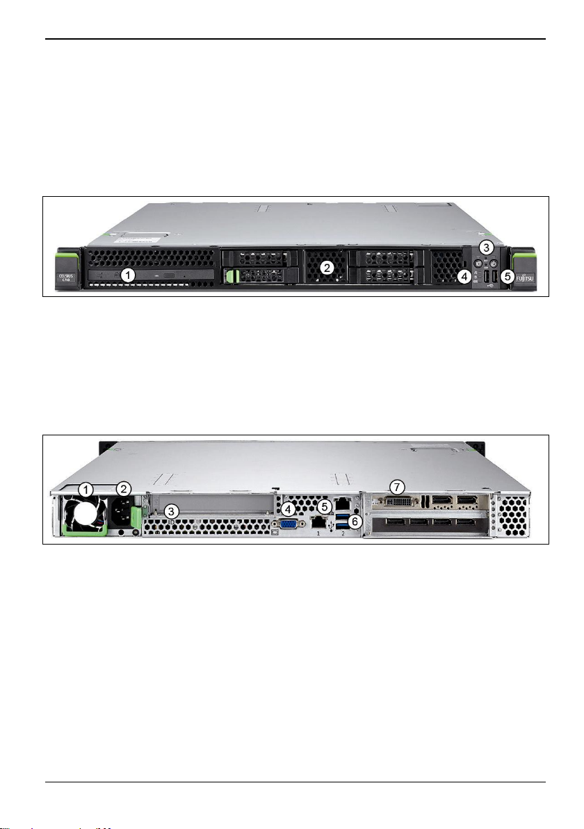
Front view
1= Optical drive 3= Buttons (see "Buttons on the device")
2= 4 non-accessible 2½ inch drives
4=
Indicators (see "
device")
5= USB ports 2.0
Indicators on the
Rear view
1= Power supply fan 5= LAN ports
2= Power connection 6= USB ports 3.0
3=
4=
ID indicator, blue
VGA monitor port
7=
Expansions on expansion cards
(optional)
Fujitsu 9
Page 14

Important notes
Important notes
Please store this Operating Manual and any other documentation close to the device. If you pass on
the device to third parties, you should also pass on the whole documentation.
Safety notes
Please observe the safety precautions in the "Safety/Regulations" manual
and the following safety notes.
This device complies with the relevant safety regulations for data processing equipment. If you have
any questions regarding whether or not you can set up the device in the intended environment,
please contact your sales outlet or our customer service centre.
● The activities described in this manual must only be performed by qualified
!
engineers. Qualified engineers are persons who have received appropriate training –
in the installation of th–e device – including hardware and software.
● Any equipment repairs must be performed by service personnel. Unauthorised
intervention in the system will result in a loss of warranty and liability exclusion.
● Disregarding the instructions in this manual and making improper repairs can
endanger the user (electric shock, energy hazard, fire risk) or damage the device.
● Before installing or uninstalling internal options in the device, switch off the device, all
peripheral devices and all other connected devices. Remove all mains plugs from the
power sockets. Otherwise there is a risk of electric shock.
Before initial startup
● During installation and before operating the device, observe any instructions on
!
10 Fujitsu
environmental conditions for your device (see "
● If the device is brought into the installation site from a cold environment,
condensation can form both inside the casing and on the outside of the casing.
● Before operating the device, wait until it is absolutely dry and has reached
approximately the same temperature as the room in which it will be used. Failure to
observe these guidelines can lead to material damage of the device.
● Transport the device only in its original packaging or other corresponding packaging
to protect it from knocks and jolts.
Technical data").
Page 15

Important notes
Initial startup and operation
● The device must only be operated at an ambient temperature in accordance with the
!
technical data (see "
● If the device is integrated in an installation supplied with power by an industrial
supply network with a Type IEC 309 connection plug, the fusing of the power supply
network must meet the requirements for non-industrial power supply networks for
plug type A.
● The device automatically sets itself to the correct voltage within the range from 100 V
to 240 V. Make sure that the local mains voltage is neither higher nor lower than this
limit value.
● This device must only be connected to properly grounded mains outlets or non-
heating sockets of the rack-internal power supply using safety-tested mains cables.
● Ensure that the device is connected to a properly grounded mains outlet and that the
device is close to the socket.
● Ensure that the sockets on the device or the properly grounded mains outlets are
freely accessible.
● The ON/OFF switch and the main switch (if available) do not disconnect the device
from the mains voltage. To completely disconnect from the mains voltage, remove all
mains plugs from the properly grounded mains outlets.
● Always connect the device and the attached peripherals to the same circuit.
Otherwise you risk losing data, e. Otherwise you risk losing data, e. if the device
continues to run during a power failure, but the peripheral device (e.g. a memory
sub-system) has failed.
● Data cables must offer sufficient shielding.
● The Ethernet cabling must meet standards EN 50173 and EN 50174-1/2 or standard
ISO/IEC 11801. As a minimum requirement, a category 5 shielded cable must be
used for 10/100 Ethernet or a category 5e cable for Gigabit Ethernet.
● Lay all cables so that nobody can stand on them or trip over them. Refer to the
relevant notes in the operating manual when connecting the device.
● No data transfer cables should be connected or disconnected during a thunderstorm
(lightning hazard).
● Ensure that no objects (e.g. jewellery, paper clips, etc.) or liquids are allowed to get
into the inside of the device (electric shock, short circuit).
● In emergencies (e.g. damaged casing, operating elements or cables, penetration of
liquids or foreign matter), switch off the device immediately, disconnect all mains
plugs from the grounded mains outlets, and contact the service team.
● Disconnect all mains plugs from the properly grounded mains outlets before
removing the air hood (rotating fans).
Technical data").
Fujitsu 11
Page 16

Important notes
● EN 60950-1/2) is only guaranteed with a completely fitted casing and built-in rear slot
!
cover plates for installation openings (electric shock, cooling, protection against fire,
radio interference suppression).
● Install only system expansions that satisfy the requirements and rules governing
safety and electromagnetic compatibility and relating to telecommunications terminal
equipment. If you install other expansions, you may damage the system or violate
the safety regulations and regulations governing RFI suppression. Information on
which system expansions are suitable can be obtained from the customer service
centre or your sales outlet.
● Components identified with a warning sign (e.g. a lightning bolt) may only be opened,
removed or exchanged by authorised specialists.
● The warranty is invalidated if the device is damaged during the installation or
replacement of system expansions.
● You may set only those resolutions and refresh rates specified in the Operating
Manual for the monitor. Otherwise you may damage the monitor. If you are in any
doubt, contact your sales outlet or customer service centre.
● Before installing or uninstalling internal options in the device, switch off the device, all
peripheral devices and all other connected devices. Remove all mains plugs from the
power sockets. Otherwise there is a risk of electric shock.
● Internal cables or devices must not be damaged or altered. This could lead to
damage to the device, make a fire break out or cause an electric shock.
● Some modules inside the device also remain hot after shut down. Wait some time
after shutting down the device before beginning to install or remove internal options.
The printed circuit boards and soldered components of the internal options are
unprotected and could be damaged by static electricity. Before handling, first touch a
metal part of the device to discharge any static electricity from the body.
● Circuitry on boards or soldered components must not be touched. Hold the printed
circuit boards by their edges or metallic areas.
● Tighten the screws that you removed during installation or removal of the internal
options into the original device or original positions again. Using different screws will
damage the device.
● We reserve the right to announce changes to the possible options for the installation
process described in this document.
12 Fujitsu
Page 17
Important notes
Cleaning the device
● Switch off the device and all equipment connected to it and remove the mains plug
!
The surfaces may be cleaned with a dry cloth. If particularly dirty, use a cloth that has been
moistened in mild domestic detergent and then carefully wrung out. You can use disinfectant wipes
to clean the outside surfaces of the keyboard and the mouse.
from the power socket.
● Do not clean any interior parts yourself, leave this job to a service technician.
● Do not use any cleaning agents that contain abrasives or may attack plastic.
● Ensure that no liquid enters the inside of the device.
● Ensure that the ventilation slots on the device and on the monitor are not covered.
● Do not use any cleaning sprays (especially not any flammable substances). Damage
to the device or a fire risk could occur.
Energy saving, disposal and recycling
You can find information on these subjects on the "Drivers & Utilities" DVD or on our
website (
i
The device must not be disposed of with household rubbish. This device is labelled in
accordance with European Directive 2002/96/EC concerning waste electrical and
electronic equipment (WEEE).
The Directive lays down the framework for the return and recycling of used electrical and
electronic equipment throughout the EU. To return your used device, please use the return
and collection systems available to you. For more information on this, go to
http://www.fujitsu.com/fts/about/fts/environment-care/.
http://www.fujitsu.com/fts/about/fts/environment-care/).
Fujitsu 13
Page 18

Important notes
CE mark
The shipped version of this device complies with the requirements of EC Directives 2004/108/EC
"Electromagnetic compatibility", 2014/30/EU "Low voltage directive", 2011/65/EU "RoHS directive"
and 2009/125/EC "Ecodesign directive".
CE mark for devices with a radio component
The shipped version of this device meets the requirements of Directive 1999/5/EC of the European
Parliament and of the Council, dated 9
CE nnnn (!) ; nnnn: For digits and exclamation mark (!), see label on the product.
You can find more information and declarations of conformity on the Internet at:
http://globalsp.ts.fujitsu.com/sites/certificates.
This equipment may be used in the following countries:
Belgium
Estonia
UK
Croatia
Luxembourg
Austria
Sweden
Spain
Cyprus
Contact the appropriate government office in the particular country for current information on possible
operating restrictions. If your country is not included in the list, please contact the appropriate
supervisory authority to establish whether the use of this product is permitted in your country.
Bulgaria Denmark Germany
Finland France Greece
Ireland Iceland Italy
Latvia Liechtenstein Lithuania
Malta The Netherlands Norway
Poland Portugal Romania
Switzerland Slovakia Slovenia
Turkey Czech Republic Hungary
EMC standard EN 55022 class A
This is a Class A device. This device may cause radio interference in residential areas. In
this case, the operator can be requested to take appropriate measures.
!
14 Fujitsu
Page 19

Important notes
FCC Compliance Statement
If the device complies with the FCC regulations, the FCC sign can be found on the type rating plate.
FCC Class A Compliance Statement
The following statement applies to the products covered in this manual, unless otherwise specified
herein. The statement for other products will appear in the accompanying documentation.
NOTE:
This equipment has been tested and found to comply with the limits for a Class A digital device,
pursuant to Part 15 of the FCC Rules and meets all requirements of the Canadian InterferenceCausing Equipment Standard ICES-003 for digital apparatus. These limits are designed to provide
reasonable protection against harmful interference in a residential installation. This equipment
generates, uses, and can radiate radio frequency energy and, if not installed and used in accordance
with the instructions, may cause harmful interference to radio communications. However, there is no
guarantee that interference will not occur in a particular installation. If this equipment does cause
harmful interference to radio or television reception, which can be determined by turning the
equipment off and on, the user is encouraged to try to correct the interference by one or more of the
following measures:
● Reorient or relocate the receiving antenna.
● Increase the separation between the equipment and receiver.
● Connect the equipment into an outlet on a circuit different from that to which the receiver is
connected.
● Consult the dealer or an experienced radio/T.V. technician for help.
Fujitsu Technology Solutions GmbH is not responsible for any radio television interference caused
by unauthorized modifications of this equipment or the substitution or attachment of connecting
cables and equipment other than those specified by Fujitsu Technology Solutions GmbH. The
correction of interference caused by such unauthorized modification, substitution or attachment will
be the responsibility of the user.
The use of shielded I/O cables is required when connecting this equipment to any and all optional
peripheral or host devices. Failure to do so may violate FCC and ICES rules.
WARNING:
This is a class A device. This equipment may cause interference in a residential installation. In this
case the user is encouraged to perform appropriate measures to correct the interference.
Fujitsu 15
Page 20

Function overview
Function overview
This section contains information about the functions of the device.
Mainboard
For the features of the mainboard, please refer to the technical manual for the D3288 mainboard for
hardware and to the BIOS Setup manual for firmware.
Hard disk drives
The device is supplied with the following drive cage: For up to four 2.5 inch SAS/SATA hard disk
drives:
Up to four 2.5 inch SAS/SATA hard disk modules can be inserted into the drive cage. Each HDD
module can accept a SAS/SATA hard disk drive in 2.5 inch format. Connection of the modules to the
SAS/SATA backplane is wire-free. This means the hard disk modules can be simply plugged in or
pulled out. Mixed configurations of SAS and SATA hard disk modules in one drive cage are not
supported.
Accessible drives/components
The hard disks cannot be changed during operation. Always shut down the device
beforehand. Please refer to section "
!
Shutting down the device".
The following location is available: one location for an Ultra-Slim DVD drive (option)
The accessible drives/components installed here cannot be changed while the computer is running.
16 Fujitsu
Page 21

Function overview
iRMC S4 with integrated management LAN port
The iRMC S4 (integrated Remote Management Controller) is a Baseboard Management Controller
(BMC) with integrated management LAN port and extended functionality. The iRMC S4 therefore
allows comprehensive control of your workstation independently of the system status, in particular,
therefore, control of your workstation when it is in "out of band" system status.
Among others, the iRMC S4 supports the following important functions:
● Browser access via the iRMC S4 own web server
● Secure communication (SSH, SSL)
● Power management for the managed device (independent of its system status)
● Power Consumption Management
● Connection of virtual drives as Remote Storage
● Text console redirection and graphical console redirection (Advanced Video Redirection)
● Provision of remote storage media (Remote Storage)
● Command Line Interface (CLI)
● Easy interactive or script-based configuration of the iRMC S4
● Own iRMC-S4 user management
● Global cross-processor iRMC S4 user administration using an LDAP directory service
● Automatic network configuration via DNS / DHCP
● Power supply of the iRMC S4 via the system's standby supply
● Comprehensive alarm management
● System Event Log (SEL) readout and editing
● IPMI support
● CIM / WS-MAN support
● Internal Event Log for checking the user login/logout
For more information on iRMC, see the "iRMC S4 – integrated Remote Manage–ment Controller"
manual (on the Fujitsu Manual Server under x86 Servers - Software - ServerView Suite - Out-Of-Band
Management).
Fujitsu 17
Page 22

Preparation for initial startup
Preparation for initial startup
Please follow the safety instructions in the "
!
When setting up your device, please read the recommendations and safety notes in the
"Safety/regulations" manual.
The device should only be set up in the intended orientation, i.e. in a horizontal position.
We recommend that you install the system in a rack. In view of the multitude of different
finishes and varnishes used on furniture, it is possible that the underside of the device will
mark the surface it stands on.
Do not expose the device to extreme environmental conditions (see "
Protect the device from dust, humidity, and heat.
Make sure that the device is adequately ventilated.
Do not stack several devices on top of each other.
Before putting it into operation, allow sufficient time for the device to acclimatise to the operating
environment:
Temperature difference (°C) (operating
environment/outside)
5 3
10 5
15 7
20 8
25 9
30 10
Important notes" section.
Technical data").
Acclimatisation time (hours)
18 Fujitsu
Page 23

Preparation for initial startup
Installation steps
This section contains an overview of the steps to be taken for installation of your device.
● As the very first step, please familiarise yourself with the safety instructions in section
Important notes" .
"
● Make sure that you have all the necessary manuals available (see section "
information"), and perhaps print out the PDF files.
● Transport the device to the desired set up location (see section "
● Unpack all the components, check the contents for any visible transportation damage and
check whether the delivery agrees with the information on the delivery note.
● Should you discover that the delivery does not correspond to the delivery note, notify your local
sales outlet immediately.
● Install the device in a rack (see section "
● Connect the cables to the device. In doing so, please take note of section "
devices".
● Connect the device to the mains power (see "
● Familiarise yourself with the operating elements and indicators on the front and rear of the
device (see section "
● Switch on the device (see section "
● Configure the device and, if necessary, install the desired operating system and the desired
applications (see section "
Ports and operating elements").
Performing system configuration").
Rack mounting and dismounting").
Connecting the device to the mains voltage").
Switching the device on").
Before initial startup").
Further
Connecting external
Fujitsu 19
Page 24

Rack mounting and dismounting
Rack mounting and dismounting
Due to its weight and external dimensions, at least two persons are required to install the
device in a rack, for safety reasons.
!
Do NOT use the QRLs (Quick Release Levers) on the front panel to lift the device into the
rack.
When connecting and disconnecting the cables, also follow the instructions in the
"Important Information" chapter of the Operating Manual for the particular rack. The
Operating Manual is supplied together with the rack when it is delivered.
When installing the rack, make sure that the anti-tilt bracket is properly fitted.
A maximum of one unit at a time may be removed from the rack, even if the anti-tilt
bracket is mounted. If several units are pulled out of the rack simultaneously, there is a
danger of the rack tipping over. Please observe the safety notes for the rack and the
corresponding warning label.
For EMEA only: The mains connection of the rack must be carried out by an authorised
professional (electrician).
If the device is integrated in an installation supplied with power by an industrial supply
network with a Type IEC 309 connection plug, the fusing of the power supply network
must meet the requirements for non-industrial power supply networks for plug type A.
Inserting a device in the rack or removing from the rack
Please observe the safety notes and the notes on rack installation in section "
notes" and section "
!
At least two persons are required to install the device in a rack and to remove the device
from a rack.
A maximum of one unit at a time may be removed from the rack, even if the anti-tilt
bracket is mounted. If several units are pulled out of the rack simultaneously, there is a
danger of the rack tipping over.
Rack mounting and dismounting"
Important
Fujitsu rack systems
The Fujitsu rack systems support the installation of PRIMERGY servers or
● PRIMECENTER Rack
● PRIMECENTER M1 Rack
● DataCenter Rack
● 19 inch standard rack
● 19 inch Slimline Rack (for Japan)
20 Fujitsu
Page 25

Rack mounting and dismounting
For information on how to mount the device in the rack, see the mounting instructions
provided with the rack installation kit. Additional information is contained in the manual for
i
the rack system.
Online documentation on rack installation can be found at:
http://manuals.ts.fujitsu.com/index.php?id=5406-5605-5606
In order to satisfy the ventilation concept and provide sufficient air to the devices, all the unoccupied
areas in the rack must be closed off with dummy covers.
The mains connection is made using the existing power strips in the particular rack (for EMEA).
Fujitsu rack systems have the following characteristics:
● Rail systems that can be mounted without tools
● Mounting systems with the facility for length adjustment, which guarantees alignment to various
rack depths.
Asymmetric PRIMECENTER and DataCenter racks offer enhanced cable management in the side
area of the rack.
3rd party racks
Installation in most current rack systems from other manufacturers (3rd party racks) is supported. For
more information, contact your responsible sales person.
Fujitsu 21
Page 26
Rack mounting and dismounting
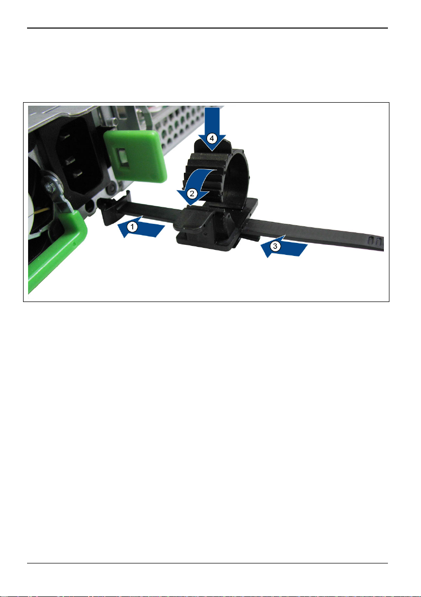
Using the cable strain relief clip
You can secure the mains cable in a cable strain relief clip to ensure that the non-heating connectors
cannot be accidentally disconnected from the device.
► Connect the cable strain relief clip at the power supply (1).
► Open the cable strain relief clip by pushing the lock in direction (2)
► Connect the mains cable to the power supply (3).
► Press the cable strain relief clip closed until it clicks into place, in order to secure the cable (4).
22 Fujitsu
Page 27

Rack mounting and dismounting
Connecting external devices
Read the documentation for the external device before connecting it.
!
With the exception of USB and FireWire devices, always disconnect all mains plugs before
connecting external devices!
Do not connect or disconnect cables during a thunderstorm.
Always take hold of the actual plug when disconnecting a cable. Never pull the cable!
Connecting cables
● Switch off all the devices concerned.
● For all the devices concerned, remove the power plugs from the power sockets.
● Connect the cables at the device and peripheral equipment. In every case, follow the safety
instructions given in the "
● Plug the data communication cables into the data/telephone network sockets.
● Insert the mains plugs into grounded mains outlets.
Disconnecting cables
● Switch off all the devices concerned.
● For all the devices concerned, remove the power plugs from the power sockets.
● Unplug the data communication connectors from the data/
telephone network sockets.
● Unplug all cables from the device and peripheral equipment.
USB and FireWire devices are hot-pluggable. This means you can connect and
disconnect the cables of USB devices while the operating system is running.
i
Additional information can be found in the "
the documentation for the USB devices.
Important notes" section and in the "Safety/regulations" manual.
Connecting external devices" section and in
Fujitsu 23
Page 28
Rack mounting and dismounting
Ports on the device
The ports are located on the front and rear of the device. The ports available on your device depend
on the configuration level you have selected. The standard ports are marked with the symbols shown
below (or similar).
VGA monitor port
USB 2.0 - Universal Serial Bus,
black
USB 3.0 - Universal Serial Bus,
i
blue
For some of the connected devices, you must install and set up special software
(e .g. drivers) (see documentation for the connected device and for the operating system).
LAN
LAN port
Connecting a monitor
► Follow the instructions provided in the monitor manual to prepare the monitor for operation
(e. g. connecting cables).
► Plug the data cable into a suitable monitor port on the device.
24 Fujitsu
Page 29

Rack mounting and dismounting
f
Connecting external devices to the USB ports
A number of external devices can be connected to the USB ports (e .g. printers, scanners, modems
or keyboards).
► Connect the data cable to the external device.
► Connect the data cable to a USB port.
► Read the documentation for the USB device to obtain full information about the installation of
Device drivers
USB devices are hot-pluggable. This means you can connect and disconnect the cables o
USB devices while the operating system is running.
i
Additional information can be found in the documentation for the USB devices.
the device.
The devices you connect to the USB ports usually require no driver of their own, as the
required software is already included in the operating system. If the device requires
i
separate software, please note the information in the manufacturer's manual.
To guarantee USB 2.0, only a max. 3 m long cab le may be used from the front USB port to
the USB peripheral device.
Simultaneous connection of components with a high current draw (e.g. external USB hard
disk drives) can cause the USB ports to shut down.
Fujitsu 25
Page 30

Connecting the device to the mains voltage
Connecting the device to the mains
voltage
In its basic configuration, the device has a non-redundant hot-plug power supply.
► Connect the connector of the mains cable to the power supply of the device (see section
► Plug the mains plug into a non-heating appliance socket on the power strip of the rack.
For more details, please refer to the technical manual for the rack.
The device automatically adjusts itself to a mains voltage of 100 V - 240 V. You may only
operate the device if the rated voltage range of the device matches the local mains
!
voltage.
"
Using the cable strain relief clip").
26 Fujitsu
Page 31

Switching the device on
Switching the device on
After the device has been connected to the mains, it takes approximately 60 seconds
before it can be switched on.
i
► Switch on the monitor (refer to the operating manual for the monitor).
► Press the ON/OFF switch on the front of your device for about half a second.
The power-on indicator lights up (see section "
Fujitsu 27
Indicators on the device") and the device starts.
Page 32

Shutting down the device
Shutting down the device
CAUTION!
!
Please follow the safety instructions in the "
This step is only necessary if you perform an upgrade or change components.
i
► Tell the system administrator that the device will be shut down and switched off line.
► Stop and close all applications.
► Shut down the device.
► Switch on the ID indicator of the device, as described in the "Identifying defective devices"
Forced shut down
If there is an ACPI-compatible operating system deployed on the system, pressing the
ON/OFF switch causes a controlled shutdown process or the device is put into Hibernate
i
mode, depending on the setting.
Pay attention to the signaling of the power-on indicator, as described in the "Indicators on
the device" section.
section.
Important notes" section.
Loss of data with this procedure!
!
If the device no longer responds to your inputs, proceed as follows:
► Press and hold the ON/OFF switch for at least 4 seconds.
The device will shut down. You can then restart it.
28 Fujitsu
Page 33

Performing system configuration
Performing system configuration
This section contains information about configuring the device and installation of the operating
system.
Configuring the onboard SATA controller
A 6-port SATA controller is integrated into the mainboard. You can thus use up to 4 non-accessible
drives, a DOM (Disk On Motherboard) and an optical drive.
Configuring the SAS/SATA Controller
The device has an optional SAS/SATA RAID Controller.
You can thus use up to 4 non-accessible drives.
Additional information on configuration of the controller is given in the "BIOS Setup"
manual.
i
Descriptions of operating systems not covered in the Controller manual are provided in the
appropriate readme files on the driver DVDs.
i
For more information on the configuration of the optional RAID Controller, see the
corresponding documentation on the Internet at http://www.fujitsu.com/fts/support.
i
Descriptions of operating systems not covered in the Controller manual are provided in the
appropriate readme files on the driver DVDs.
i
Fujitsu 29
Page 34

Performing system configuration
Systems without a pre-installed operating system
Installing the operating system
Configure the device and install the desired operating system and the desired applications.
► Switch the device on.
► Install the operating system.
► During installation, follow the instructions on screen.
► Install the latest driver and updates from the "Drivers & Utilities" DVD.
For further information about the system and its drivers, utilities and updates please refer
to the "Drivers & Utilities" DVD or visit our website at http://www.fujitsu.com/fts/support.
i
Systems with a pre-installed operating system
Depending on the version, your device can be delivered with an operating system already preinstalled.
Once the installation has been started the device must not be switched off, unless the
installation has been completed!
!
During the installation process, do not restart the device unless you are requested to do
so!
Otherwise the installation will not be carried out correctly and the contents of the hard disk
will have to be completely restored.
If the device will be included in a network, the user, device and network protocol details
are required during the software installation.
i
Contact your network administrator if you have any questions about this information.
When you switch on the device for the first time, the supplied software is installed and
configured. Plan a reasonable amount of time for this, as this process must not be
interrupted.
You may need the licence number for Windows during the installation. The licence number
is located on a sticker on your device.
For further information about the system and its drivers, utilities and updates please refer
to the "Drivers & Utilities" DVD or visit our website at http://www.fujitsu.com/fts/support.
i
30 Fujitsu
Page 35

Operation
Operation
Buttons on the device
The following buttons are found on the front:
Symbol Designation Description
ON/OFF switch If the system is switched off, press the ON/OFF switch to
ID Identification (ID)
RST
NMI
button
Reset button Pressing the Reset button reboots the system.
NMI button WARNING: Do NOT touch! Possible loss of data. The NMI
switch it on.
If the system is operating, press the ON/OFF switch to switch
the system off.
WARNING: Possible loss of data.
The ON/OFF switch does not disconnect the device from the
mains voltage. To completely disconnect from the mains
voltage, you must remove the mains plug from the power
socket.
When the ID button is pressed, the ID indicators light up
(blue) on the front and rear of the device. Both ID indicators
light synchronously.
WARNING: Possible loss of data.
button is only for use by Service.
Fujitsu 31
Page 36

Operation
Indicators on the device
Symbol Designation Description
ID ID indicator (blue) Lights up blue if the system was selected when the ID
Power-on
indicator
(green/orange/
yellow)
Hard disk activity
indicator (green)
Global error
indicator (orange)
button was pressed. Pressing the button again
deactivates the indicator.
The ID indicator can also be activated via the ServerView
Operations Manager and the iRMC-S4 web interface. In
addition, its status can be reported to the ServerView
Operations Manager and the iRMC S4.
● Lights green when the device is switched on.
● Lights orange when the system is in shutdown
mode (shutting down of the operating system) or is
switched off.
Lights green when an internal drive is being accessed.
● Lights orange if a pre-failure event was detected,
which requires a (preventive) service action.
● Flashes orange if a fault was detected, which
requires a service action.
● Unlit if there is no critical event present.
After a power failure, the indicator is activated after the
restart, provided that the event is still acute.
The indicator also lights in standby mode.
You can obtain more details of the indicated faults from
the System Event Log (SEL) or query them using the web
user interface of the iRMC S4.
32 Fujitsu
Page 37

Operation
LAN indicators
The LAN ports can be found on the rear of your device. Every LAN port has two LEDs, which
indicate the speed (right) or activity (left) of the LAN transfer.
No. Designation Description
1 LAN port 1
2 LAN Port 2
(managed/shared)
The LED on the left:
● lights green when an LAN connection is present.
● is unlit when there is no LAN connection.
● flashes green if an LAN transfer is occurring.
The LED on the right:
● lights yellow: LAN transfer 1 Gbit/s
● lights green: LAN transfer 100 Mbit/s
● unlit: LAN transfer 10 Mbit/s
Fujitsu 33
Page 38

Operation
Optical drive
This product contains an LED classified in accordance with IEC 60825-1:2007: LASER
CLASS 1, and therefore must not be opened.
!
It is dangerous to look directly at this beam.
Never remove casing parts of the optical drive!
Handling CDs/DVDs
Observe the following guidelines when handling CD/DVDs:
● Avoid touching the surface of a CD/DVD. Only hold CDs/DVDs by their edges!
● Only use CDs/DVDs that are in good condition, in order to prevent data loss,
damage to the device and injuries.
● Check each CD/DVD for damage, cracks, breakage etc. before inserting it in the
drive.
● Always store CDs/DVDs in their cases. This will protect them from dust, scratches
and other damage.
● Do not dirty the CD/DVD surface with fingerprints, oil, dust, etc. Remove any dirt or
marks by wiping them with a soft, dry cloth from the centre of the disk to the outside.
Do not use benzene, thinners, water, vinyl record spray, anti-static agents or cloths
impregnated with silicon.
● Protect your CDs/DVDs from dust, mechanical vibration and direct sunlight!
● Avoid storing CDs/DVDs in areas subject to high temperatures or humidity. Avoid
high levels of humidity and dust concentrations in the air.
● When a CD/DVD/BD is moved from a cold place to a warm place, condensation can
occur on its surface, which can result errors when reading the data. In such cases,
clean the CD/DVD/BD with a soft, dry cloth in a radial direction, and then leave it to
dry in the air. Do not dry the CD/DVD/BD with a hairdryer or similar device.
● Vibrations and shocks are also to be avoided.
● Do not bend CDs/DVDs and do not place heavy objects on top of them.
● Do not write on the labelling side (printed side) with a ballpoint pen or pencil.
● Please note that additionally affixed stickers change
● the mechanical properties of a CD/DVD and can result in imbalance.
● Damaged and imbalanced CDs/DVDs can break at high drive speeds (data loss).
● Sharp-edged pieces of broken CDs/DVDs may penetrate the cover of the optical
drive (damage to the system) and be thrown out of the unit (danger of injury,
particularly to unprotected parts of the body, such as the face and neck).
When using poor quality CDs/DVDs, vibrations and reading errors may occur.
34 Fujitsu
Page 39

Operation
Handling the drive
!
● You may use 12 cm / 4.72 inch CDs/DVDs in the optical drive. Do not use any
business card CDs or other small CDs.
● Never place objects other than the specified CDs/DVDs in the drive.
● Do not push, pull or use other rough action on the CD/DVD tray of the drive.
● Do not dismantle the optical drive.
● Before use, clean the tray of the optical drive with a soft, dry cloth.
● If liquids like water or metal objects like paper clips get into a drive, this can cause
electric shock and/or device failures.
● By way of precaution, remove the data carrier from the optical drive if you do not
intend to use it for a long period of time. Keep the optical drive tray closed to
prevent foreign matter, such as dust, from getting into the drive.
Take the following precautions to prevent damage to the optical drive and the CDs/DVDs,
i
and to prevent premature wear of the data carriers:
● Only insert the CDs/DVDs in the drive when needed and remove them after use.
● Store the data carriers in suitable sleeves.
● Protect the data carriers from exposure to heat and direct sunlight.
Fujitsu 35
Page 40

Settings in BIOS Setup
Settings in BIOS Setup
In BIOS Setup you can set the system functions and the hardware configuration of the
device.
i
On delivery, the default values are effective (see the "BIOS Setup" manual or the manual
for the mainboard). You can customise these settings in the BIOS Setup, in accordance
with your requirements.
36 Fujitsu
Page 41

Property and data protection
Property and data protection
The device has a lockable rack door to protect against unauthorised access.
BIOS Setup security functions can be enabled to protect the system and data against unauthorised
access internally.
Mechanical casing lock (optional)
With the casing lock, you can mechanically lock the casing to prevent unauthorised persons from
opening it. The keys can be found on the rear panel of your device.
i
In addition to the casing lock, an open and a closed lock are also illustrated:
Locking the casing
► Turn the key towards the closed lock .
Releasing the casing
► Turn the key towards the open lock .
Fujitsu 37
Page 42

Property and data protection
BIOS Setup security functions
In the BIOS Setup, the Security menu offers you various options for protecting your personal data
against unauthorised access, e.
● Prevent unauthorised access to the BIOS Setup
● Prevent unauthorised system access
● Prevent unauthorised access to the settings of boards with their own BIOS
● Output virus warnings
● Protect BIOS from being overwritten
● Protect the device from being switched on by an external device
You can also combine these functions.
For a detailed description of the Security menu and how to assign passwords, see the manual for the
mainboard or the "BIOS Setup" manual.
38 Fujitsu
Page 43

Troubleshooting and tips
Troubleshooting and tips
When you connect or disconnect cables, follow the safety instructions in the
"Safety/Regulations" manual and in the "
!
If a fault occurs, try to correct it as described in the following documentation:
● in this section
● in the documentation for the connected devices
● in the help facilities of the individual programs
● in the documentation for the operating system used
Help if problems occur
Should you encounter a problem with your device that you cannot resolve yourself:
► Note the ID number of your device. The ID number can be found on the type rating plate on the
top face of the casing.
► For further clarification of the problem, contact the Service Desk for your country (see the
Service Desk list or visit the Internet at http://support.ts.fujitsu.com/contact/servicedesk).
Identifying defective devices
When working in a data centre environment, you should enable easy identification of the ID
indicators on the front and rear connector panels of the device (see section "
elements").
► Activate the ID indicator by pressing the ID button on the front of the device once.
► As soon as you have successfully completed the maintenance task, deactivate the ID indicator
by pressing the ID button again. The ID indicator can also be activated via the ServerView
Operations Manager and the iRMC-S4 web interface. In addition, its status can be reported to
the ServerView Operations Manager and the iRMC S4.
Important notes" section.
Ports and operating
Fujitsu 39
Page 44

Troubleshooting and tips
Troubleshooting
Power-on indicator fails to light after switching on
Cause Troubleshooting
The mains voltage supply is faulty.
The device cannot be switched off with the ON/OFF switch.
Cause Troubleshooting
System crash
► Check whether the power cable is plugged into the
device and a grounded mains outlet correctly.
► Switch the device on.
► The device cannot be switched off with the ON/OFF
switch.
The operating system is not shut-down properly in the
process. Error messages are therefore possible the next
time the system is booted.
It may take a few seconds before the system boots. This
is while the system carries out a check.
40 Fujitsu
Page 45

Troubleshooting and tips
Monitor stays blank
Cause Troubleshooting
Monitor is switched off.
Power saving has been activated
(monitor is blank).
Brightness control set to dark.
Mains cable is not connected.
Monitor cable is not connected.
► Switch the monitor on.
► Press any key on the keyboard.
or
► Deactivate the screen saver. If necessary, enter the
appropriate password.
► Adjust the brightness control. For detailed
information, please refer to the operating manual
supplied with your monitor.
► Switch off the monitor and the device.
► Check that the monitor mains cable is properly
connected to the monitor and to a grounded mains
outlet or to the monitor socket of the device.
► Check that the device mains cable is properly
plugged into the device and a grounded mains
outlet.
► Switch on the monitor and the device.
► Switch off the monitor and the device.
► Check that the monitor cable is properly connected
to the device and to the monitor.
► Switch on the monitor and the device.
Fujitsu 41
Page 46

Troubleshooting and tips
No mouse pointer displayed on the monitor
Cause Troubleshooting
The mouse is not properly connected. ► Shut down the operating system correctly.
► Switch the device off.
► Check that the mouse cable is properly connected.
If you are using an adapter or extension for the
mouse cable, check these connections too.
► Make sure that only one mouse is connected.
► Switch the device on.
Time and/or date incorrect
Cause Troubleshooting
Time and date are wrongly set.
► Set the correct time and date under the operating
system you are using.
or
► Set the time or date in the BIOS Setup.
Error message on the monitor
Error messages and their explanations are contained in the documentation for the programs used.
Installing new software
When installing programs or drivers, important files may be overwritten and modified. You should
make a backup copy of the contents of the hard disk before performing an installation so that you
can still access the original data in the event of any problems following installation.
Restoring hard disk contents
Instructions for this are given on the case of the Recovery DVD.
42 Fujitsu
Page 47

Troubleshooting and tips
Tips
Topic Tip
Lack of system resources
Other manuals
If you have too many applications running at once, you
may experience problems due to a lack of system
resources.
► Close unnecessary applications.
or
► Run the applications in a different order.
You can find other manuals as PDF files on the Internet at
http://www.fujitsu.com/fts/support.
Fujitsu 43
Page 48

System expansions
System expansions
As the device has to be shut down to install or remove system expansions, it is a good
idea to print out some parts of this section.
i
It may be necessary to update the BIOS when carrying out a system expansion or
hardware upgrade. Additional information is contained in the "BIOS Setup" manual or,
where applicable, in the technical manual for the mainboard.
When installing components that become very hot, make sure that the maximum
permissible temperature is not exceeded.
The components are very similar to each other. For this reason, the device is shown in the
following illustrations. Any differences will be pointed out at the appropriate point.
This section describes all the activities which must be carried out when hardware changes are to be
made in the device (e. g. installing boards or drives).
Read the supplied documentation before installing new drives and/or boards.
Read the technical manual for the mainboard before making any expansion to the mainboard.
The device must be switched off when installing/removing the system expansions and
must not be in energy saving mode.
!
Remove the mains plug from the power socket before opening the device.
44 Fujitsu
Page 49

System expansions
Information about boards
Take care with the locking mechanisms (catches and centring pins) when you are replacing boards
or components on boards.
To prevent damage to the board or the components and conductors on it, please take care when you
insert or remove boards. Make sure expansion boards are inserted in a straight manner.
Never use sharp objects (screwdrivers) for leverage.
Boards with electrostatic sensitive devices (ESD) can be identified by the
sticker shown.
When handling boards fitted with ESDs, you must always observe the
following points:
● Switch the device off and disconnect the mains plug from the grounded
A detailed description of how to protect sensitive components from the effects of
electrostatic discharge can be found in the relevant European and international standards
i
(EN 61340-5-1, ANSI/ESD S20.20).
mains outlet before installing/removing components with ESDs.
● You must statically discharge yourself (e. g. by touching an earthed
object), before working with modules.
● The equipment and tools you use must be free of static charge.
● When installing components, use a suitable earthing cable to connect
them to the system unit.
● Always hold boards by their edges.
● Only touch or hold the components by the edge or at the areas marked
green (Touch Points).
● Never touch connector pins or conductors on the board.
● Set down all components on a surface which is free of static charge.
Fujitsu 45
Page 50

System expansions
Opening the device
Requirement:
● The device is removed from the rack (see section "
from the rack").
CAUTION!
!
• Before you remove or secure any covers, switch off the device, all other peripheral
devices and all other connected devices. Remove all mains plugs from the power
sockets. Otherwise the device could be damaged by short circuits if objects were to
fall in (e.g. screws).
• After finishing the maintenance work you must replace the casing cover to ensure
cooling, to comply with EMC (Electromagnetic Compatibility) regulations and to
protect against fire.
• Please follow the safety instructions in the "Important notes" section.
• Make sure that the device is shut down (see section "Shutting down the device").
Inserting a device in the rack or removing
► Where applicable, open the casing lock.
► Unlatch the casing cover by pressing in the two release buttons on the sides of the casing (1).
► Push the casing cover about 1 cm back.
► Lift the casing cover away upwards.
46 Fujitsu
Page 51

System expansions
Closing the device
CAUTION!
!
• Before closing the device, make certain that there are no unnecessary components
or tools left inside the device.
• Take care that no cables become trapped when the cover is put in place.
► Place the casing cover on the device.
► Slide the casing cover forwards until it reaches the stop.
► The cover latches automatically.
► Where applicable, close the casing lock.
► Install the device in the rack again (see section "
the rack").
Fujitsu 47
Inserting a device in the rack or removing from
Page 52

System expansions
Overview of the installation openings and drives in your device
The casing has space for several accessible and non-accessible drives:
● one location for an accessible 5¼ inch drive (optical drive, ODD)
● four locations for non-accessible 2½ inch drives (hard disks, HDD/SSD)
1 = Location for accessible 5¼ inch drive
2 = Drive cage for four non-accessible 2½ inch drives
Removing and installing an accessible 5¼ inch drive (optical drive, ODD)
Removing an accessible 5¼ inch drive
Requirements:
● The device is removed from the rack (see section "
from the rack").
● The casing is open (see section "
► Disconnect the cables connected to the drive.
48 Fujitsu
Opening the device").
Inserting a device in the rack or removing
Page 53

System expansions
► Unscrew the screw (1) on the drive cage.
► Slide the drive in the direction of the arrow.
► Lift the drive cage out of the device.
Fujitsu 49
Page 54

System expansions
► Undo the screws holding the drive in the drive cage.
► Take the drive out of the drive cage.
► If necessary, make the required settings on the remaining hard disk drives. If required, you
must adjust the entry for the drive in the BIOS Setup accordingly.
► If you do not install an accessible drive, close off the open drive bay with the optional cover.
► Close the device (see section "
► Install the device in the rack again (see section "
Closing the device").
Inserting a device in the rack or removing from
the rack").
50 Fujitsu
Page 55

System expansions
Installing an accessible 5¼ inch drive
Requirements:
● The device is removed from the rack (see section "
from the rack").
● The casing is open (see section "
Opening the device").
Inserting a device in the rack or removing
► Undo the screw (1) and remove the drive cage from the device.
► If necessary, remove the cover of the drive bay.
► Slide the drive into the drive cage and secure it with three screws.
► Slide the drive cage into the drive bay in the direction of the arrow.
► Tighten the screw (1).
Fujitsu 51
Page 56

System expansions
► Connect the data and power supply cables.
► Close the device (see section "
► Install the device in the rack again (see section "
the rack").
Closing the device").
Inserting a device in the rack or removing from
Removing and installing non-accessible drives (hard disks, HDD/SSD)
CAUTION!
!
• Removal of a hard disk drive or solid state drive from the installation frame must only
be performed by a service technician.
• The HDD/SSD modules (drives) must all be uniquely labelled so that they can be put
back in their original locations after an upgrade. If you do not do this, existing data
can be destroyed.
• The device does not support any hot-plug functions. Always shut down the device to
change drives. See section "
For more information on the configuration of the optional RAID Controller, see the
documentation in the RAID Controller.
• Circuitry on boards or soldered components must not be touched. Hold the boards by
their edges or metallic areas.
• Before you remove a unit, wait for about 30 seconds until the data carrier has come
to a complete standstill.
• During start-up, drives may briefly cause the device to resonate, producing a buzzing
noise. However, this does not mean that there is a fault. As soon as the drives have
reached their normal speed, the buzzing noise stops.
• Depending on the operating system, you may configure any write cache settings for
the hard disk drive. Should a power failure occur during an active write cache, data
could be lost.
• For your own security, before disposing of a hard disk drive or solid state drive,
delivering it to a third party or returning it, you should destroy any data saved on the
drive.
• Rough handling of hard disk drives can cause damage to the saved data. Before you
attempt to resolve unexpected problems, always make a backup copy of important
data. When backing up data onto another hard disk drive, you should proceed by
each file or partition.
• Take care that the hard disk drive is not subjected to any impacts and that it does not
come into contact with any metal objects.
• Use the device on a shock-free and vibration-free surface.
• Do not use the device in very hot or very cold locations, or where there are extreme
changes in temperature.
• Never try to dismantle a hard disk drive or a solid state drive.
Shutting down the device".
52 Fujitsu
Page 57

System expansions
Removing and installing non-accessible 2½ inch drives (hard disks, HDD/SSD)
A maximum of four non-accessible 2½ inch SAS/SATA HDD/SSD modules can be installed. Each
HDD/SSD module can accept a SAS/SATA hard disk drive or a SATA solid state drive in 2.5 inch
format. The connection of the HDD/SSD modules to the SAS/SATA backplane is wire-free. This
allows the HDD/SSD modules to be simply plugged in or pulled out.
Mixed configurations of SAS and SATA HDD/SSD modules are not supported.
• If only one HDD/SSD module is installed, this must be placed in position 0. The remaining free
locations must be occupied by an empty module.
Removing a 2½ inch empty module
Empty modules protect free locations from environmental influences. Remove the empty
module before installing an additional drive.
i
► Press together the two tongues on the empty module until the clip releases (1).
► Pull the empty module out of its location (2).
Fujitsu 53
Page 58

System expansions
CAUTION!
!
Keep the empty module. If you have removed a drive and not replaced it with a new one,
then the empty module must be reinstalled for cooling purposes, to comply with the
conditions of the EMC (electromagnetic compatibility) regulations and to protect against
fire. Make certain that the empty module engages properly in the location.
Installing a non-accessible 2½ inch drive
Requirements:
● The empty module is removed (see section "
Removing a 2½ inch empty module").
► To release the locking mechanism of the drive, press together the two green tabs of the locking
lever (1).
► Swing the grip of the drive fully in the direction of the arrow (2).
The drive is released.
54 Fujitsu
Page 59

System expansions
► Carefully slide the drive into the free location (1) until it reaches a stop.
► Press the grip fully in the direction of the arrow (2) until the locking mechanism engages.
Where appropriate, you must adjust the entry for the drive in the BIOS-Setup or in the
configuration of the RAID Controller.
i
Fujitsu 55
Page 60

System expansions
Removing a non-accessible 2½ inch drive
Requirements:
● You have made certain that the drive to be removed has not been combined in a RAID array. If
the drive is part of a RAID array, you must first of all delete the array.
For more information on the configuration of the optional RAID Controller, see the
corresponding documentation on the Internet at http://www.fujitsu.com/fts/support.
i
CAUTION!
!
All data on all the drives in the array will be lost. Perform a backup before you delete a
RAID array.
► To release the locking mechanism of the drive, press together the two green tabs of the locking
lever.
► Swing the grip of the drive fully in the direction of the arrow (1).
The drive is released.
► Pull out the drive (2).
56 Fujitsu
Page 61

System expansions
Installing a 2½ inch empty module
Requirement:
● The drive is removed (see section "
Removing a non-accessible 2½ inch drive").
► Slide the empty module into the empty location until it engages.
Fujitsu 57
Page 62

System expansions
Installing and removing fan modules
Depending on configuration, the device has up to 6 system fans.
i
If no fan is installed at one of the positions in your device, a placeholder made of foam
must be installed at this position. To ensure optimum cooling of the device, the
placeholder must not be removed under any circumstances.
Numbering of the fan modules:
58 Fujitsu
Page 63

System expansions
Removing a defective fan module
Requirements:
● The device is removed from the rack (see section "
from the rack").
● The casing is open (see section "
CAUTION!
!
The fans are powerful, high-speed models. Never remove the fans during operation,
because there is an increased risk of injury in doing so.
Opening the device").
Inserting a device in the rack or removing
► Pull the connector of the fan module out of the socket of the fan cable.
Fujitsu 59
Page 64

System expansions
► Lift the fan module by about 2 cm. To do this, press the four rubber pins upwards (A).
► Slide the fan cable through the opening of the fan cage.
► Lift out the fan module.
60 Fujitsu
Page 65

System expansions
Installing a new fan module
► Guide the fan cable forwards through the opening in the fan cage and insert the fan module.
► Press the four rubber pins (A) downwards until they engage.
Fujitsu 61
Page 66

System expansions
► Connect the connector of the fan module into the socket of the fan cable.
► Close the device (see section "
► Install the device in the rack again (see section "
Closing the device").
Inserting a device in the rack or removing from
the rack").
62 Fujitsu
Page 67

System expansions
Expansion cards
CAUTION!
!
• Internal cables or devices must not be damaged or altered. This could lead to damage
to the device, make a fire break out or cause an electric shock.
• Some modules and components inside the device also remain hot after shut down.
After shutting down the device, wait until hot components have cooled before you
install or remove internal options.
• Printed circuit boards and soldered components of the internal options are unprotected
and could be damaged by static electricity. You must statically discharge yourself (e.g.
by touching an earthed object), before working with modules, before replacing
electrostatic sensitive devices (ESDs).
• Circuitry on boards or soldered components must not be touched. Hold the circuitry by
the metallic parts or the edges.
• If devices are installed or dismantled by methods other than those described in this
section, the warranty becomes invalid.
Because of the two riser modules, the system offers one slot for a high profile board (1) and one slot
for a high profile board or graphic card (2), 2 slots.
1=
Riser module for high profile boards
(expansion card installed), max. card
length 180 mm
Fujitsu 63
2=
Display adapter carrier for high profile
boards, 2 Slots, max. card length
341 mm
Page 68

System expansions
Occupancy of the PCI slots
No. Riser module PCI bus Length
1 Riser module PCI Express High profile
2 Display adapter carrier PCI Express High profile, 2 Slots
64 Fujitsu
Page 69

System expansions
Installing an expansion card in the riser module (high profile)
Removing the riser module
Requirements:
● The device is shut down (see section "Shutting down the device").
● The device is removed from the rack (see section "
from the rack").
● The casing is open (see section "
Opening the device").
Inserting a device in the rack or removing
► Carefully pull the riser module up and out.
Fujitsu 65
Page 70

System expansions
Removing a slot cover
► Undo the screw (1).
► Pull the slot cover out.
66 Fujitsu
CAUTION!
!
Keep the slot cover for use later. If you remove the expansion card again and do not insert
a new one instead, you must replace the slot cover for cooling purposes, to comply with
the conditions of the EMC (electromagnetic compatibility) regulations and to protect
against fire.
Page 71

System expansions
Inserting an expansion card
► First of all, read the documentation supplied with the expansion card.
► Gently push the expansion card into the riser module slot until you feel it click into place (1).
► Ensure that the projection on the slot cover (2) engages in the appropriate recess (B).
► Secure the slot cover of the expansion card with the screw (3).
► Where necessary, plug in the cables required for connection to the expansion card
For more information on the optional cables, please refer to the documentation for the
expansion card and the mainboard manual.
i
Fujitsu 67
Page 72

System expansions
Installing the expansion card carrier
► Plug the riser card into the slot of the mainboard.
► Where necessary, connect the cables of the expansion card with the mainboard.
► Close the device (see section "
► Install the device in the rack again (see section "
Closing the device").
Inserting a device in the rack or removing from
the rack").
68 Fujitsu
Page 73

System expansions
Installing an expansion card in the display adapter carrier
Remove the display adapter carrier
Requirements:
● The device is shut down (see section "
● The device is removed from the rack (see section "
from the rack").
● The casing is open (see section "
Shutting down the device").
Inserting a device in the rack or removing
Opening the device").
► Open the two locking tabs in the direction of the arrow (1).
► Carefully pull the display adapter carrier up and out.
Fujitsu 69
Page 74

System expansions
Removing slot covers
► Undo the screw (1).
► Fold the locking lever in the direction of the arrow.
► Pull the slot covers out.
70 Fujitsu
CAUTION!
!
Keep the slot cover of the slot. If you remove the expansion card again and do not insert a
new one, you must replace the slot cover for cooling purposes, to comply with the
conditions of the EMC (electromagnetic compatibility) regulations and to protect against
fire.
Page 75

System expansions
Inserting an expansion card
► Please read the documentation supplied with the expansion card.
Display adapter carrier for ISA-compliant display adapter:
If you are using this type of display adapter, you will need an extender to achieve the ISA
length (max. 341 mm in accordance with the ISA specification).
i
► If necessary, plug the power supply cable onto the expansion card.
► Where necessary, loosen the screws (1) on the carrier (2) and slide the carrier to the right.
► Gently push the expansion card into the riser card slot in the direction of the arrow until you feel
it click into place.
► Ensure that the projection on the slot cover (B) engages into the appropriate recess.
Fujitsu 71
CAUTION!
!
Only with the correct fastening can enough cooling and compliance with the EMC
regulations be ensured.
Page 76

System expansions
► Close the locking lever and secure the expansion card with the screw (1).
72 Fujitsu
Page 77

System expansions
Display adapter carrier for ISA-compliant display adapter:
► Push the carrier in the direction of the arrow until the expansion card is securely fixed.
► Tighten the screws again (1).
Fujitsu 73
Page 78

System expansions
Installing a display adapater carrier
► If necessary, connect the power supply cable of the expansion card to the mainboard.
► Plug the display adapater carrier carefully in the direction of the arrow (1) into the slot of the
mainboard. Take care that no cables become trapped.
► Lock the two locking slides in the direction of the arrow (2).
► Close the device (see section "
► Install the device in the rack again (see section "
the rack").
74 Fujitsu
If you have installed or removed an expansion card, please check the settings for the
corresponding slot in the BIOS Setup. Change the settings if necessary.
i
Further information on this can be found in the documentation for the expansion card.
Closing the device").
Inserting a device in the rack or removing from
Page 79

System expansions
Installing a backup unit (FBU) (only in conjunction with a RAID Controller)
The backup unit (FBU) ensures the storage content of the RAID Controller is maintained if there is a
power failure.
Requirements:
● The device is shut down (see section "
● The device is removed from the rack (see section "
● The casing is open (see section "
Installing the FBU into the FBU carrier
CAUTION!
!
• Do not use excessive force when connecting the cable, as the connector is fragile.
• Please follow the safety instructions in the "Important notes" section.
Shutting down the device").
from the rack").
Opening the device").
Inserting a device in the rack or removing
► Place the FBU at a slight angle under the two brackets of the FBU-carrier, as illustrated.
► While sliding the FBU in, press the locking lever down as shown.
Fujitsu 75
Page 80

System expansions
► Slide the FBU into the location and make sure that you hear the FBU engage.
► Connect the cable of the FBU as shown.
76 Fujitsu
Page 81

System expansions
Installing the backup unit with the FBU carrier
Position of the key holes on the underside of the FBU:
Fujitsu 77
Page 82

System expansions
Counterpart in the casing:
► Insert the FBU carrier into the casing so that the three heads of the shoulder screws pass into
the open ends of the keyholes on the underside of the FBU.
78 Fujitsu
Page 83

System expansions
► Slide the FBU carrier in the direction of the arrow.
The heads of the shoulder screws engage in the open ends of the key holes on the FBU carrier.
► Make sure that the locking slide on the FBU carrier properly engages (see circle).
Fujitsu 79
Page 84

System expansions
Connecting the FBU cable to the RAID Controller
► Install a RAID Controller (see section "Expansion cards").
► Connect the FBU cable to the RAID Controller as described in the manual for the RAID
Controller. You can find an electronic version of the manual for the RAID Controller on the
Internet at http://www.fujitsu.com/fts/support.
Laying the FBU cable
► Route the FBU cable as shown in the illustration (1).
80 Fujitsu
Page 85

System expansions
Final steps
► Close the device (see section "Closing the device").
► Install the device in the rack again (see section "
the rack").
Inserting a device in the rack or removing from
Removing and installing the processor heat sink
Removing the hood
► Undo the two screws (see circles).
Fujitsu 81
Page 86

System expansions
► Lift the hood slightly at the side, as shown, and then lift it out of the casing.
82 Fujitsu
Page 87

System expansions
Removing the heat sink
Requirements:
● The device is removed from the rack (see section "
from the rack").
● The casing is open (see section "
● The hood is removed (see section "
Opening the device").
Removing the hood").
Inserting a device in the rack or removing
► Undo the four screws on the heat sink (1).
► Lift the heat sink out of the casing (2).
You can now change the processor (see section "
Fujitsu 83
Changing the processor").
Page 88

System expansions
Installing the heat sink
Requirements:
● The device is removed from the rack (see section "
from the rack").
● The casing is open (see section "
Opening the device").
Inserting a device in the rack or removing
► Reinstall the heat sink so that the air flow is fed towards the back of the casing (see arrow on
the heat sink).
► Press the heat sink downwards and secure it with four screws, tightening them diagonally.
► Replace the hood (see section "
► Close the device (see section "
► Install the device in the rack again (see section "
the rack").
84 Fujitsu
Removing the hood").
Closing the device").
Inserting a device in the rack or removing from
Page 89

System expansions
Installing the hood
► Reinstall the hood in the casing at a slight angle. Ensure that you insert the projection on the
hood (1) into the recess for the power supply (see circle).
Fujitsu 85
Page 90

System expansions
► Fit the hood in the casing as shown.
86 Fujitsu
Page 91

System expansions
► Tighten the two screws (see circles).
Fujitsu 87
Page 92

System expansions
Mainboard expansions
For more information on how to upgrade the main memory or the processor of your device, see the
manual for the mainboard.
Upgrading main memory
Requirements:
● The device is removed from the rack (see section "
from the rack").
● The casing is open (see section "
● The hood is removed (see section "
► Upgrade the main memory according to the description in the manual for the mainboard.
► Replace the hood (see section "
► Close the device (see section "
► Install the device in the rack again (see section "
the rack").
Opening the device").
Removing the hood").
Installing the hood").
Closing the device").
Changing the processor
Requirements:
● The device is removed from the rack (see section "
from the rack").
● The casing is open (see section "
● The hood is removed (see section "
● The processor heat sink is removed (see section "
► Change the processor as described in the manual for the mainboard.
► Replace the processor heat sink (see section "
► Replace the hood (see section "
► Close the device (see section "
► Install the device in the rack again (see section "
the rack").
Opening the device").
Removing the hood").
Installing the hood").
Closing the device").
Inserting a device in the rack or removing
Inserting a device in the rack or removing from
Inserting a device in the rack or removing
Removing the heat sink").
Installing the heat sink").
Inserting a device in the rack or removing from
88 Fujitsu
Page 93

System expansions
Changing the front panel module
The front panel module consists of the front panel board, a control panel and a bracket. These
components are already pre-assembled.
As well as the CPU and casing temperature sensors of the mainboard, the front panel has its own
sensor for the ambient temperature. If the temperature sensor for the ambient temperature becomes
defective, the front panel board must be changed.
Removing the front panel module
Requirements:
● The device is shut down (see section "
● The device is removed from the rack (see section "
● The casing is open (see section "
CAUTION!
!
Do not change the front panel module at the same time as the mainboard. If both
components are changed at the same time, it may not be possible to restore the system
configuration data onto the mainboard.
Shutting down the device").
from the rack").
Opening the device").
Inserting a device in the rack or removing
► Disconnect the front panel cable from the
front panel module (1).
► Press the catch downwards with a
screwdriver until it disengages (2).
Fujitsu 89
Page 94

System expansions
► Slide the front panel module forwards (3)
and remove it.
90 Fujitsu
Page 95

System expansions
Installing a new front panel module
► Insert the front panel module with the lower
catch first (1).
► Tilt the front panel module upwards (2) and
slide it towards the device until the upper
catch engages (3).
Fujitsu 91
Page 96

System expansions
► Connect the control panel cable to the front
panel module.
► Make absolutely certain that the polarity of
the cable is correct. The connector and the
socket are coded.
► Close the device (see section "
device").
► Install the device in the rack again (see
section "
removing from the rack").
Inserting a device in the rack or
Closing the
92 Fujitsu
Page 97

System expansions
Replacing the Lithium battery
In order to permanently save the system information, a lithium battery is installed to provide the
CMOS-memory with a current. A corresponding error message notifies the user when the charge is
too low or the battery is empty. The lithium battery must then be replaced.
Incorrect replacement of the lithium battery may lead to a risk of explosion!
!
The lithium battery may be replaced only with an identical battery or with a type
recommended by the manufacturer.
Do not throw lithium batteries into the household waste. They must be disposed of in
accordance with local regulations concerning special waste.
Make sure that you observe the correct polarity when replacing the lithium battery. The
positive terminal must be at the top!
The lithium battery holder exists in different designs that function in the same way.
All batteries containing harmful substances are identified with a symbol (crossed-out
garbage bin). In addition, the marking is provided with the chemical symbol of the heavy
metal decisive for the battery's classification as a pollutant.
● Cd Cadmium
● Hg Mercury
● Pb Lead
2
2
1
► Press the catch in the direction of the arrow (1).
The battery jumps out of the holder slightly.
► Remove the battery (2).
Push the new lithium battery of the same type into the holder (3) and press it downward until it
engages.
Fujitsu 93
3
3
Page 98

Technical data
Technical data
CELSIUS C740
Electrical data
Safety standards complied with: IEC 60950-1:2005 (Second Edition), Am 1: 2009,
Protection class: I
Rated voltage range: 100 - 240 V
Rated frequency range: 50 - 60 Hz
Max. rated current: 6.5 A – –3.0 A
Dimensions
Width x Depth x Height: 431 mm (483 mm) x 683 mm x 42.8 mm /
19-inch rack mount: Yes
Rack installation kit: Rack installation kit available as an option
Weight
In basic configuration: 11 kg / 24.25 lbs
Ambient conditions
Environment class 3K2
Environment class 2K2
Temperature
Operation (3K2) 10 °C .... 35 °C /
Transportation (2K2) –25 °C .... 60 °C /
Luftfeuchtigkeit 10% ... 85% (non-condensing)
The formation of condensation is not permitted while the device is in operation!
The data sheet of the device contains further technical data. You can find the data sheet
on the Internet at http://fujitsu.com/fts/support.
i
EN 60950-1:2006 + A1:2010+ A11:2009 +
A12:2011, CAN/CSA-C22.2 No. 60950-1-07 2ed.
2014 (MOD) ANSI/UL 60950-1-2014
16.96 inch (19.01 inch) x 26.88 inch x 1.68 inch
DIN IEC 721 part 3-3
DIN IEC 721 part 3-2
50 °F …. 95 °F
–13 °F …. 140 °F
94 Fujitsu
Page 99

Index
Index
A
Ambient conditions 94
B
battery 93
BIOS-Setup
Settings 36
Board 45
C
CD/DVD
Handling 34
CD/DVD Drivers&Utilities 13
CE mark 14
Cleaning the device 13
Connecting a monitor 24
Connecting cables 23
Connecting external devices 24
D
Date
Date not correct 42
Device
Connecting devices 23
Expansions 44
Indicators 32
Device Port 24
Devices
connecting 23, 25
Dimensions 94
Disconnecting cables 23
disposal 13
E
Electrical data 94
Electromagnetic compatibility 14
Energy saving 13
Error
Date 42
device 40
monitor 41
Mouse 42
Time 42
Error message 42
ESD 45
Expansions
Device 44
External devices
connecting 23, 25
connecting Port 24
F
First time switching on 27
H
Hardware Controller 36
I
Important notes 10
Indicator
Device 32
Initial startup 18
Installing new software 42
L
Low voltage directive 14
M
Malfunction
device 40
monitor 41
Mouse 42
Manuals, others 43
Monitor
no screen display 41
Port 24
stays blank 41
Mouse
error 42
Mouse pointer 42
N
Notational conventions 8
Note
Boards 45
CE mark 14
O
Optical drive 34
Other manuals 43
P
Power-on indicator
does not light up 40
unlit 40
Problemsolving 39
Fujitsu 95
Page 100

Index
R
recycling 13
Replacing the Lithium battery 93
Restoring hard disk contents 42
S
Select
the Lithium battery 93
Settings in BIOS Setup 36
Setup, see BIOS-Setup
Signs and symbols 8
Software
Installing new software 42
Storage
insufficient storage 43
Surface 94
Switching on the monitor 27
Switching the device on 27
System Controller 36
System expansion 44
T
Technical data 94
The device cannot be switched off with the
ON/OFF switch. 40
Time
Time not correct 42
Tips 39
to the USB ports 24
Ü
Übersicht, Gerät 7
U
USB
Universal Serial Bus 24
USB devices
connecting 25
USB port
Connecting devices 25
W
Weight 94
X
XE Storage
insufficient storage 43
96 Fujitsu
 Loading...