

Page 1

PRIMERGY BX630 S2
Scalable Server Blade
Operating Manual
Edition October 2008
Page 2

Comments… Suggestions… Corrections…
The User Documentation Department would like to
know your opinion of this manual. Your feedback helps
us optimize our documentation to suit your individual
needs.
Feel free to send us your comments by e-mail to
manuals@ts.fujitsu.com.
Certified documentation
according to DIN EN ISO 9001:2000
To ensure a consistently high quality standard and
user-friendliness, this documentation was created to
meet the regulations of a quality management system
which complies with the requirements of the standard
DIN EN ISO 9001:2000.
cognitas. Gesellschaft für Technik-Dokumentation mbH
www.cognitas.de
Copyright and Trademarks
Copyright © 2009 Fujitsu Technology Solutions GmbH.
© cognitas. Gesellschft für Technik-Dokumentation mbH 2009 Pfad: H:\April\PRIMERGY_Rebranding\von Walte r\bx630_s2_ba\Archiv\bx630s2-ba-en \OBJ_DOKU-2533-002.fm
All rights reserved.
Delivery subject to availability; right of technical modifications reserved.
All hardware and software names used are trademarks of their respective manufacturers.
Page 3

Contents
1 Preface . . . . . . . . . . . . . . . . . . . . . . . . . . . . . . 5
1.1 Concept and target group of this manual . . . . . . . . . . . . 6
1.2 Documentation overview . . . . . . . . . . . . . . . . . . . . 7
1.3 Features . . . . . . . . . . . . . . . . . . . . . . . . . . . . . . 8
1.4 Notational conventions . . . . . . . . . . . . . . . . . . . . 12
1.5 Technical data . . . . . . . . . . . . . . . . . . . . . . . . . 13
2 Overview: Installation Procedure . . . . . . . . . . . . . . . 15
3 Important notes . . . . . . . . . . . . . . . . . . . . . . . . . 17
3.1 Notes on safety . . . . . . . . . . . . . . . . . . . . . . . . . 17
3.2 CE conformity . . . . . . . . . . . . . . . . . . . . . . . . . 20
3.3 Environmental protection . . . . . . . . . . . . . . . . . . . 20
4 Installing the Hardware . . . . . . . . . . . . . . . . . . . . 23
4.1 Installation Steps . . . . . . . . . . . . . . . . . . . . . . . . 23
4.2 Unpacking the Server Blade . . . . . . . . . . . . . . . . . . 23
4.3 Installing the Server Blade in the Basic Unit . . . . . . . . . 24
4.4 Connecting Devices . . . . . . . . . . . . . . . . . . . . . . 28
5 Installation and Operation . . . . . . . . . . . . . . . . . . . 31
5.1 Control and Connection Panel . . . . . . . . . . . . . . . . 32
5.2 Switching the Server Blade On/Off . . . . . . . . . . . . . . 35
5.3 Configuring the Server Blade . . . . . . . . . . . . . . . . . 35
5.4 Updating the Firmware (BIOS and BMC) . . . . . . . . . . . 38
BX630 S2 Operating Manual
Page 4

Contents
6 BIOS Setup . . . . . . . . . . . . . . . . . . . . . . . . . . . . 39
6.1 Entering the BIOS Setup . . . . . . . . . . . . . . . . . . . . 43
6.2 Operation . . . . . . . . . . . . . . . . . . . . . . . . . . . . . 44
6.3 Main menu . . . . . . . . . . . . . . . . . . . . . . . . . . . . 46
6.4 Advanced menu . . . . . . . . . . . . . . . . . . . . . . . . . 48
6.4.1 Peripheral Configuration . . . . . . . . . . . . . . . . . . . . . 50
6.4.2 Advanced System Configuration . . . . . . . . . . . . . . . . . 53
6.4.3 Power On/Off menu . . . . . . . . . . . . . . . . . . . . . . . . 54
6.4.4 IPMI menu . . . . . . . . . . . . . . . . . . . . . . . . . . . . 56
6.4.4.1 IPMI LAN parameters . . . . . . . . . . . . . . . . . . . . . 59
6.5 Security menu . . . . . . . . . . . . . . . . . . . . . . . . . . 60
6.6 Server menu . . . . . . . . . . . . . . . . . . . . . . . . . . . 63
6.6.1 CPU Status . . . . . . . . . . . . . . . . . . . . . . . . . . . . 65
6.6.2 Memory Status . . . . . . . . . . . . . . . . . . . . . . . . . . 67
6.6.3 Console Redirection . . . . . . . . . . . . . . . . . . . . . . . 69
6.7 Boot menu . . . . . . . . . . . . . . . . . . . . . . . . . . . . 71
6.8 Exit menu . . . . . . . . . . . . . . . . . . . . . . . . . . . . 72
© cognitas. Gesellschft für Technik-Dokumentation mbH 2008 Pfad: H:\April\PRIMERGY_Rebranding\von Walte r\bx630_s2_ba\Archiv\bx630s2-ba-en \OBJ_DOKU-2537-002.fm
7 Troubleshooting and Tips . . . . . . . . . . . . . . . . . . . . 73
8 Hot-plug components . . . . . . . . . . . . . . . . . . . . . . 75
8.1 Hot-plug disk drives . . . . . . . . . . . . . . . . . . . . . . . 75
8.2 Handling hard disk drives and HDD modules . . . . . . . . . 77
8.3 Installing/removing the dummy module . . . . . . . . . . . . 78
8.4 Installing/removing a hard disk module . . . . . . . . . . . . 79
Abbreviations . . . . . . . . . . . . . . . . . . . . . . . . . . . . . . . . 83
Index . . . . . . . . . . . . . . . . . . . . . . . . . . . . . . . . . . . . 87
Operating Manual BX630 S2
Page 5
1 Preface
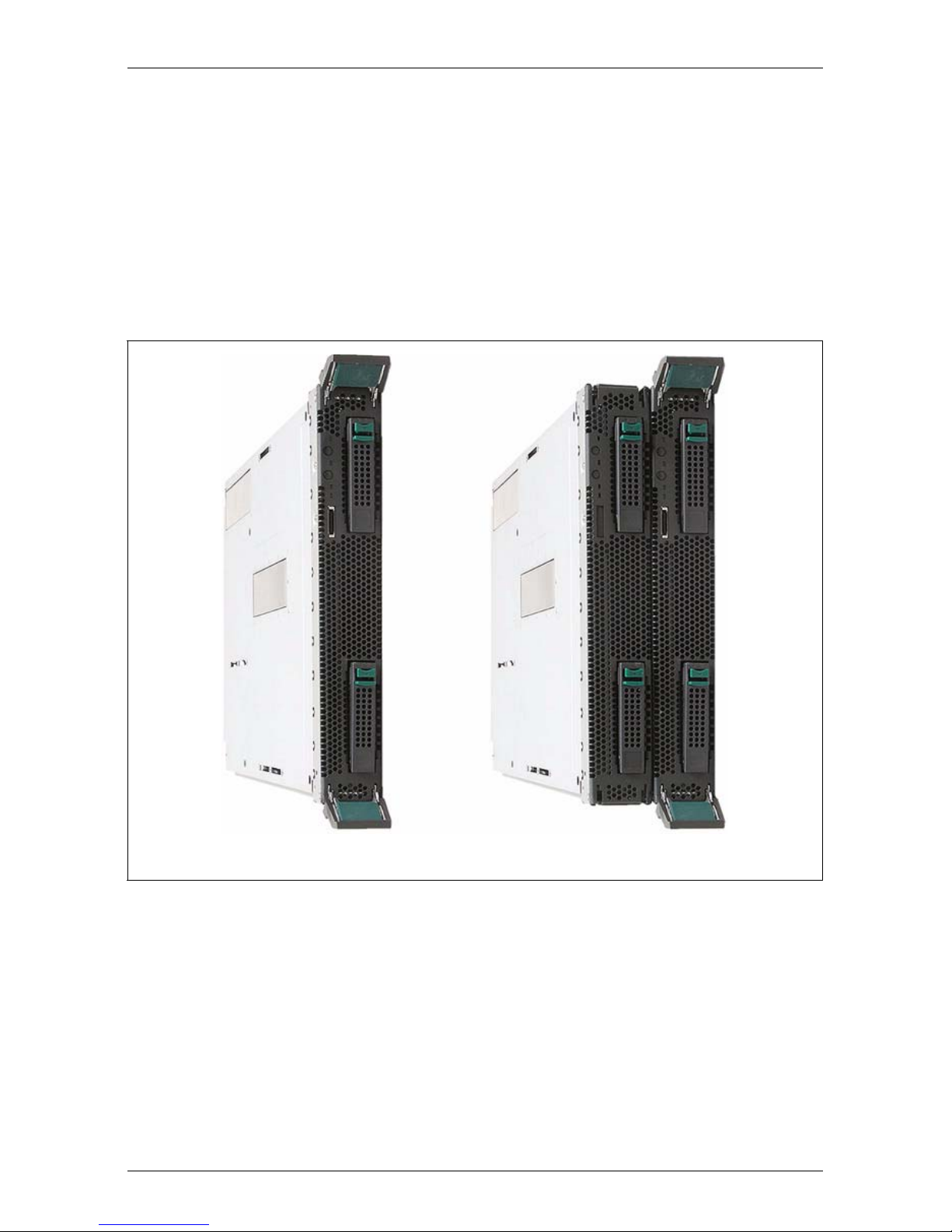
The PRIMERGY BX630 S2 server blade is a scalable AMD-based dual-socket
server blade. It offers several new forward-looking technologies such as quadcore processors, 2.5-inch SAS or SATA-II hard disk drives, four 1-Gbit/s
onboard Ethernet LAN channels and an optional dual-channel 4-Gbit/s Fibre
Channel (FC) connection. Two BX630 S2 dual-socket server blades can be
connected to form a quad-socket server blade with 16 processor cores.
Dual-socket server blade Quad-socket server blade
Figure 1: PRIMERGY BX630 S2 configurations
The PRIMERGY BX630 S2 scalable server blade is designed for the BX600 S3
basic unit, but it can also be installed in slots 1-3 and 5-9 of the BX600 S2 basic
unit.
I In the latter case, however, only 2 of the 4 onboard Ethernet channels of
the BX630 S2 server blade can be used.
Security functions in the BIOS Setup protect the data on the server blade from
unauthorized manipulation.
BX630 S2 Operating Manual 5
Page 6

Concept and target group of this manual Preface
Depending on the configuration, the PRIMERGY BX630 S2 scalable server
blade occupies one or two slots in the PRIMERGY BX600 S2 or the BX600 S3
basic unit.
1.1 Concept and target group of this manual
This operating manual is intended for those responsible for installing the
hardware and ensuring that the system runs smoothly. It contains all the information you need to put your PRIMERGY BX630 S2 server blade into operation.
The information in this manual refers to the BX630 S2 dual-socket server blade.
How to connect two BX630 S2 dual-socket server blades to form a quad-socket
server blade is described in the Options Guide.
For a brief overview of the installation steps see chapter 2 on page 15ff.
To understand the various expansion options, you will need to be familiar with
the fields of hardware and data transmission and you will require a basic
knowledge of the underlying operating system.
© cognitas. Gesellschft für Technik-Dokumentation mbH 2008 Pfad: H:\April\PRIMERGY_Rebranding\von Walte r\bx630_s2_ba\Archiv\bx630s2-ba-en \OBJ_DOKU-2504-002.fm
6 Operating Manual BX630 S2
Page 7

Preface Documentation overview
1.2 Documentation overview
Information on your PRIMERGY BX630 S2 is provided in the following
documents:
– Flyer "Quick Start Software - Quick Installation Guide" (only provided as
hard copy)
– Manual "Safety Notes and other Important Information"
– Manual "Guarantee"
– Manual "Ergonomics"
– Manual "Returning used devices"
– Flyer "Helpdesk"
– Operating Manual for PRIMERGY BX630 S2 Scalable Server Blade
– Options Guide for PRIMERGY BX630 S2 Scalable Server Blade
I PRIMERGY manuals are available in PDF format on the ServerBooks
DVD. The ServerBooks DVD is part of the ServerView Installation
Manager Suite supplied with every server.
The PDF files of the manuals can also be downloaded free of charge
from the Internet. The overview page showing the online documentation
available on the Internet can be found using the URL:
http://manuals.ts.fujitsu.com. The PRIMERGY server documentation can
be accessed using the Industry standard servers navigation option.
If you need a replacement copy of the ServerBooks DVD, send the
details of your server to the following e-mail address: rlc@ts.fujitsu.com.
Further sources of information:
– Manual for the monitor
– Documentation for boards and drives
– Documentation for your operating system
– Information files on your operating system
I For information on installing and operating PRIMERGY BX6xx server
blades that applies to all server blade models, see the operating manual
for your PRIMERGY BX600 S2 or BX600 S3 basic unit.
BX630 S2 Operating Manual 7
Page 8

Features Preface
1.3 Features
Processors
In the BX630 S2 dual-socket server blade, one (basic configuration) or two
AMD Opteron quad-core processors of the 23xx DP and 83xx MP series ensure
extremely high data throughput and system performance.
All processors have a 2-MB second-level cache (SLC).
I It is not possible to use CPUs with different clock rates or cache capacity
in a server blade.
In the BX630 S2 quad-socket server blade, only processors of the
Opteron 83xx MP series are allowed.
For upgrading processors see the Options Guide; for exchanging processors
see the Service Supplement.
Memory
The BX630 S2 dual-socket server blade has eight memory slots. Each
processor is assigned four memory slots. Two memory slots make up one
memory bank. The memory slots must be fitted by bank, i.e. with pairs of
© cognitas. Gesellschft für Technik-Dokumentation mbH 2008 Pfad: H:\April\PRIMERGY_Rebranding\von Walte r\bx630_s2_ba\Archiv\bx630s2-ba-en \OBJ_DOKU-2504-002.fm
memory modules. The server blade supports memory modules of the type
DDR2 667 with 512 MB, 1 GB, 2 GB or 4 GB capacity, so the maximum configuration is 32 GB (64 GB in a quad-socket server blade). ECC with memory
scrubbing and ChipKill™ are supported. Only memory modules of the same
capacity can be installed in the same memory bank.
How to install memory modules is described in the Options Guide.
LAN availability
The BX630 S2 dual-socket server blade has two onboard Ethernet LAN
controllers with two 1-Gbit/s Ethernet channels each. The Ethernet LAN
connection can be implemented via switch blades or via pass-thru blades on the
back of the basic unit. For more information see the operating manual for the
basic unit.
I You can only use the two 1-Gbit/s Ethernet channels of the second
onboard LAN controller in connection with the BX600 S3 basic unit and
the Gbit Ethernet LAN switch blade (SB9f) 12 x 1 Gbit.
8 Operating Manual BX630 S2
Page 9

Preface Features
Graphics controller
The PRIMERGY BX630 S2 scalable server blade has an onboard graphics
controller (Matrox MGA-200) which is integrated in the iRMC controller. You can
connect a monitor via the VGA interface (via breakout cable) on the front of the
server blade or via the KVM blade on the back of the basic unit.
Optional Fibre Channel or Ethernet I/O module (daughter card)
You can fit the BX630 S2 dual-socket server blade with an I/O daughter card to
connect to a SAN or for additional Ethernet connections. The BX630 S2 quadsocket server blade allows two I/O daughter cards to be installed.
To be able to use the additional I/O functionality, at least one FC pass-thru blade
or switch blade, or Ethernet pass-thru blade or switch blade must be installed in
slot NET3 of the basic unit.
The following I/O daughter cards are available:
– 4-Gbit/s Fibre Channel I/O module (PCIe), allows transfer rates of 1, 2 or 4
Gbit/s and supports multiple Fibre Channel storage subsystems with the
corresponding versions.
I You can operate the 4-Gbit/s Fibre Channel I/O module only with a
BX600 S3 basic unit and only in combination with a Brocade SW4016 D4 Fibre Channel switch blade or with a 4 Gbit FC pass-thru
blade. For more information see the operating manual for the
BX600 S3 basic unit.
– Gigabit Ethernet I/O module (PCIe), also supports TOE (TCP/IP offload
engine) and iSCSI
– 10-Gbit Ethernet I/O module (PCIe)
I The 10-Gbit Ethernet I/O module (PCIe) can only be used in combi-
nation with a 10-Gbit switch blade 10/2. For more information see the
operating manual for the basic unit.
I You must not install server blades with different I/O modules in the same
BX600 S2 or BX600 S3 basic unit.
How to install I/O modules later is described in the Options Guide.
BX630 S2 Operating Manual 9
Page 10

Features Preface
High availability and reliability
When memory data is accessed, 1-bit errors in the main memory are recognized and automatically corrected with the ECC (Error Correcting Code)
method.
ASR&R (Automatic Server Reconfiguration and Restart) restarts the system in
the event of an error and automatically "hides" the defective system components.
The PDA (Prefailure Detection and Analyzing) technology from Fujitsu
Technology Solutions analyzes and monitors all components that are important
for system reliability.
The onboard SAS RAID controller supports RAID levels 0 and 1 by default, thus
increasing the system's availability. If you are using SATA-II hard disk drives, you
can implement RAID levels 0 and 1 using Promise 20319 to increase the
system's availability.
Server management
Server management is implemented using the supplied ServerView software and
PDA technology. PDA reports the threat of a system error or overloading to the
system administrator in good time, so that preventive measures can be taken.
© cognitas. Gesellschft für Technik-Dokumentation mbH 2008 Pfad: H:\April\PRIMERGY_Rebranding\von Walte r\bx630_s2_ba\Archiv\bx630s2-ba-en \OBJ_DOKU-2504-002.fm
ServerView allows the management of all PRIMERGY servers in the network via
a central console. ServerView supports the following functions:
● Monitoring of the ambient and CPU temperatures
● Watchdog timer for Automatic Server Reconfiguration and Restart (ASR&R)
if memory modules or processors fail
● Power monitoring
● End-of-life monitoring of the fans with prefailure notification
● Watchdog timer for monitoring the operating system and applications with
ASR&R
The supplied deployment software simplifies and speeds up the installation of
multiple servers. For further information see the relevant documentation.
For further information on the ServerView server management software see the
relevant documentation.
10 Operating Manual BX630 S2
Page 11

Preface Features
ServerView Installation Manager
The enclosed ServerView Installation Manager software allows you to configure
your server system quickly according to your requirements. User-friendly
menus guide you through the installation of the server operating systems.
Service and support
PRIMERGY servers have a service-friendly, modular architecture, thus
enabling quick and simple maintenance. The flash-EPROM program supplied
with the utilities from Fujitsu Technology Solutions allows fast BIOS updating via
the USB interface.
The two redundant hot-pluggable management blades of the PRIMERGY
BX600 S2 and BX600 S3 basic unit with independent LAN and COM ports for
administration allow complete remote administration of the server blade.
Together they allow remote diagnosis for system analysis, remote configuration
and a remote restart even in the event of an operating system failure or
hardware errors.
BX630 S2 Operating Manual 11
Page 12

Notational conventions Preface
1.4 Notational conventions
The following notational conventions are used in this manual:
Text in italics indicates commands or menu items.
“Quotation marks” indicate names of chapters and terms that are being
emphasized.
Ê describes activities that must be performed in the order
shown.
V CAUTION! pay particular attention to texts marked with this symbol.
Failure to observe this warning may endanger your life,
destroy the system or lead to the loss of data.
I indicates additional information, notes and tips.
© cognitas. Gesellschft für Technik-Dokumentation mbH 2008 Pfad: H:\April\PRIMERGY_Rebranding\von Walte r\bx630_s2_ba\Archiv\bx630s2-ba-en \OBJ_DOKU-2504-002.fm
12 Operating Manual BX630 S2
Page 13

Preface Technical data
1.5 Technical data
Electrical specifications
Power consumption ~ 380 W (full configuration)
Thermal dissipation min. ~ 750 kJ/h,
max. ~ 1000 kJ/h
Compliance with regulations and standards
Product safety and
ergonomics
Electromagnetic
compatibility
IEC 60950-1 / EN 60950-1, UL/CSA 60950-1,
CNS 14336 / GB 4943 / EN 50371
FCC class A
CNS 13438 class A; VCCI class A
AS/NZS CISPR 22 class A / GB 9254 class A
GB 17625
Interference emissions EN 55022 class A
Harmonic current EN 61000-3-2
Flicker EN 61000-3-3
Interference immunity EN 55024, EN 300386
CE marking
to EU directives
Low Voltage Directive 2006/95/EC
(Product Safety)
Electromagnetic Compatibility 2004/108/EC
Certification
Product safety
Global CB
Europe ENEC
Germany GS, CE
USA/Canada CSA
Japan VCCI
China/Taiwan BSMI
BX630 S2 Operating Manual 13
/ CSA
US
C
Page 14

Technical data Preface
Mechanical specifications
Width 286 mm
Depth 470 mm (520 mm incl. handles and plugs)
Height 43 mm (quad-socket server blade: 86 mm;
1 or 2 slots in the basic unit)
Weight
Max. 6 kg (quad-socket server blade: 12 kg).
Ambient conditions
Environment class 3K2
Environment class 2K2
EN 60721 / IEC 721 Part 3-3
EN 60721 / IEC 721 Part 3-2
Temperature:
Operation (3K2) 5 °C .... 35 °C
Transport (2K2) -20 °C .... 60 °C
Humidity 10%...85%
© cognitas. Gesellschft für Technik-Dokumentation mbH 2008 Pfad: H:\April\PRIMERGY_Rebranding\von Walte r\bx630_s2_ba\Archiv\bx630s2-ba-en \OBJ_DOKU-2504-002.fm
Condensation during operation must be avoided!
14 Operating Manual BX630 S2
Page 15

2 Overview: Installation Procedure
This chapter provides an overview of the steps you must perform to install your
PRIMERGY BX630 S2 scalable server blade in your basic unit. The links take
you to the sections with more detailed descriptions of the individual steps.
Ê First read the chapter “Important notes” starting on page 17, in particular the
section “Notes on safety”.
Ê Unpack the server blade, check the delivery for damage sustained during
transport and that the delivery corresponds to the specifications in the
delivery note (see section 4.2 on page 23).
Ê Mount the server blade into your BX600 S2 or BX600 S3 basic unit (see
section 4.3 on page 24).
Ê Familiarize yourself with the control and display elements on the front of the
server blade (see chapter “Installation and Operation” on page 31).
Ê Install the operating system and the applications on the server blade.
To do this, you have the following options:
– Cloning the server blade from a remote image server using RemoteDeploy.
This is recommended if the following are available:
– the RemoteDeploy software
– a suitable clone image
– a deployment server and a LAN connection
– Remote installation with ServerView Installation Manager
This installation method is recommended if a LAN connection and a
DHCP server (deployment server) are available but the requirements for
cloning are not met.
BX630 S2 Operating Manual 15
Page 16

Overview: Installation Procedure
– Local installation with or without ServerView Installation Manager
The local installation is the least convenient method. It is only recommended if the requirements for a remote installation or cloning are not
met.
If you want to use an operating system that is not supported by
ServerView Installation Manager, you can of course install it directly without
ServerView Installation Manager.
I For more information on the remote or local installation of server
blades see the ServerView Installation Manager manual, which contains
a Quick Step Guide and a detailed description of the individual installation options and wizards. A PDF version of the ServerView
Installation Manager manual is available on the PRIMERGY
ServerBooks DVD.
For how to clone server blades see the RemoteDeploy manual (a
PDF file is available on the PRIMERGY ServerBooks DVD).
For information on installing and operating the PRIMERGY BX600 S2 or
BX600 S3 basic unit, see the operating manual of your basic unit.
© cognitas. Gesellschft für Technik-Dokumentation mbH 2008 Pfad: H:\April\PRIMERGY_Rebranding\von Walte r\bx630_s2_ba\Archiv\bx630s2-ba-en \OBJ_DOKU-2505-002.fm
16 Operating Manual BX630 S2
Page 17

3 Important notes
This chapter provides safety instructions which you must observe when
handling your server blade.
3.1 Notes on safety
I The following safety instructions are also provided in the manual “Safety
notes and other important information”.
This device complies with the relevant safety regulations for IT equipment,
including electronic office machines for use in an office environment.
If you have any questions, please contact your sales outlet or the Fujitsu
Technology Solutions customer service center.
V CAUTION!
The activities described in this manual should only be performed by
engineers, service personnel or technical specialists. Equipment repairs
should only be performed by qualified staff! Any failure to observe the
guidelines in this manual could endanger the user (through electric
shock, fire hazards) or damage the equipment. Please note that any
unauthorized opening of the device will result in the invalidation of the
warranty and exclusion from all liability.
Before setting up
V CAUTION!
● During installation and before operating the device, please read the
instructions on environmental conditions for your device (see section
“Technical data” on page 13).
● If the device is brought in from a cold environment, condensation may
form both inside and on the outside of the machine.
Before operating the device, wait until it is absolutely dry and has
reached approximately the same temperature as the installation site.
Failure to observe these guidelines can lead to material damage of
the device.
BX630 S2 Operating Manual 17
Page 18

Notes on safety Important notes
V CAUTION!
● Transport the device only in its original packaging or in packaging
which protects it from knocks and jolts.
Installation and operation
V CAUTION!
● Read the notes on installation and operation in the operating manual
for your BX600 S2 or BX600 S3 basic unit.
Batteries
V CAUTION!
● Incorrect replacement of batteries can lead to risk of explosion. The
batteries may only be replaced with identical batteries or with a type
recommended by the manufacturer (see Options Guide).
● Do not throw batteries into the trash can. They must be disposed of
in accordance with local regulations on special waste.
● The German battery act obligates consumers in Germany to return
waste batteries to the distributor or to the return points established by
© cognitas. Gesellschft für Technik-Dokumentation mbH 2008 Pfad: H:\April\PRIMERGY_Rebranding\von Walte r\bx630_s2_ba\Archiv\bx630s2-ba-en \OBJ_DOKU-2506-002.fm
Please note the following:
● If you pass the system on to someone else, you should also give them the
corresponding documentation.
the public waste management authorities.
● Replace the lithium battery on the system board only as described in
the Options Guide.
● All batteries containing pollutants are marked with a crossed-out
garbage can accompanied by the chemical symbol of the heavy
metal that classifies the battery as a pollutant:
Cd Cadmium
Hg Mercury
Pb Lead
18 Operating Manual BX630 S2
Page 19

Important notes Notes on safety
Modules with Electrostatic-Sensitive Devices
Modules with electrostatic-sensitive devices are identified by the following
sticker:
Figure 2: ESD label
When you handle components fitted with ESDs, you must always observe the
following points:
● Switch off the system and remove the power plugs from the power outlets
before installing or removing components with ESDs.
● You must always discharge static build-up (e.g. by touching a grounded
object) before working with such components.
● Any devices or tools that are used must be free of electrostatic charge.
● Wear a suitable grounding cable that connects you to the external chassis of
the system unit.
● Always hold components with ESDs at the edges or at the points marked
green (touch points).
● Do not touch any connectors or conduction paths on an ESD.
● Place all the components on a pad which is free of electrostatic charge.
I For a detailed description of how to handle ESD components, see the
relevant European or international standards (EN 61340-5-1,
ANSI/ESD S20.20).
BX630 S2 Operating Manual 19
Page 20

CE conformity Important notes
3.2 CE conformity
The system complies with the requirements of the EC directives
2004/108/EC regarding “Electromagnetic Compatibility” and
2006/95/EC “Low Voltage Directive”. This is indicated by the CE
marking (CE = Communauté Européenne).
3.3 Environmental protection
Environmentally-friendly product design and development
This product has been designed in accordance with the Fujitsu Technology
Solutions standard for “environmentally friendly product design and development”. This means that key factors such as durability, selection and labeling
of materials, emissions, packaging, ease of dismantling and recycling have
been taken into account.
This saves resources and thus reduces the harm done to the environment.
Energy-saving information
© cognitas. Gesellschft für Technik-Dokumentation mbH 2008 Pfad: H:\April\PRIMERGY_Rebranding\von Walte r\bx630_s2_ba\Archiv\bx630s2-ba-en \OBJ_DOKU-2506-002.fm
Devices that do not need to be constantly switched on should be switched off
until they are needed as well as during long breaks and after completion of work.
Packaging information
Do not throw away the packaging. You may need it later for transporting the
system. If possible, the equipment should only be transported in its original
packaging.
Information on handling consumables
Please dispose of printer consumables and batteries in accordance with the
applicable national regulations.
In accordance with EU directives, batteries must not be disposed of with
unsorted domestic waste. They can be returned free of charge to the manufacturer, dealer or an authorized agent for recycling or disposal.
All batteries containing pollutants are marked with a symbol (a crossed-out
garbage can). They are also marked with the chemical symbol for the heavy
metal that causes them to be categorized as containing pollutants:
20 Operating Manual BX630 S2
Page 21

Important notes Environmental protection
Cd Cadmium
Hg Mercury
Pb Lead
Labels on plastic casing parts
Please avoid sticking your own labels on plastic parts wherever possible, since
this makes it difficult to recycle them.
Returns, recycling and disposal
The device must not be disposed of with domestic waste. This
device is labeled in compliance with European directive
2002/96/EC on waste electrical and electronic equipment (WEEE).
This directive sets the framework for returning and recycling used
equipment and is valid across the EU. When returning your used
device, please use the return and collection systems available to
you. Further information can be found at
www.ts.fujitsu.com/recycling
..
Details regarding the return and recycling of devices and consumables within
Europe can also be found in the “Returning used devices” manual, via your local
Fujitsu Technology Solutions branch or from our recycling center in Paderborn:
Fujitsu Technology Solutions
Recycling Center
D-33106 Paderborn
Tel. +49 5251 8 18010
Fax +49 5251 8 18015
BX630 S2 Operating Manual 21
Page 22

© cognitas. Gesellschft für Technik-Dokumentation mbH 2008 Pfad: H:\April\PRIMERGY_Rebranding\von Walte r\bx630_s2_ba\Archiv\bx630s2-ba-en \OBJ_DOKU-2506-002.fm
Page 23

4 Installing the Hardware
V CAUTION!
Make sure you observe the safety notes in the chapter Important notes.
The server blade must not be exposed to extreme environmental conditions (see “Ambient conditions” on page 14). It must be protected from
dust, humidity and heat.
4.1 Installation Steps
The installation steps are described in detail in the following sections of this
chapter:
● Unpacking the system ( see 4.2 on page 23).
● Installing the server blade in the basic unit (see 4.3 on page 24).
● Connecting the server blade (see 4.4 on page 28).
4.2 Unpacking the Server Blade
V CAUTION!
Make sure you observe the safety notes in the chapter “Important notes”
on page 17 starting on page 17.
Unpack the server blade only at the place where you want to set it up.
Keep the original packaging of the server blade. You may need it for future
transport.
Ê Unpack all the individual parts.
Ê Check the delivery for damage sustained during transport.
Ê Check that the delivery corresponds to the specifications in the delivery
note.
The type label is located at the front right on the underside of the server blade.
If the delivery is damaged or does not match the delivery note, contact your
supplier immediately!
BX630 S2 Operating Manual 23
Page 24

Installing the Server Blade in the Basic Unit Installing the Hardware
Notify your supplier immediately if you discover any transport damage or if the
packaging content does not match the delivery note.
4.3 Installing the Server Blade in the Basic Unit
Depending on the configuration, the PRIMERGY BX630 S2 Scalable Server
Blade occupies one or two of the ten slots in the PRIMERGY BX600 S2 or
BX600 S3 basic unit. This section describes how to install the BX630 S2 dualsocket server blade in the basic unit.The BX630 S2 quad-socket server blade is
installed in the same way.
V CAUTION!
● Make sure you observe the safety notes and the information on
handling electrostatic-sensitive devices in the section “Notes on
safety” on page 17.
● Server blade boots automatically after installation in a switched-
on BX600 S3 basic unit with management blade S3.
If you insert a BX630 S2 server blade into a switched-on BX600 S3
basic unit with management blade S3, the server blade will automatically perform a POST (Power-On Self-Test) and then switch itself off.
© cognitas. Gesellschft für Technik-Dokumentation mbH 2008 Pfad: H:\April\PRIMERGY_Rebranding\von Walte r\bx630_s2_ba\Archiv\bx630s2-ba-en \OBJ_DOKU-2507-002.fm
You may not switch off the server blade during the automatic boot
process!
If the BX600 S3 basic unit is switched off when the server blade is
installed, the POST will be performed automatically after the basic
unit is switched on.
● PRIMERGY BX630 S2 server blades are not for use in slots 4 an 10
of the PRIMERGY BX600 S2 basic unit.
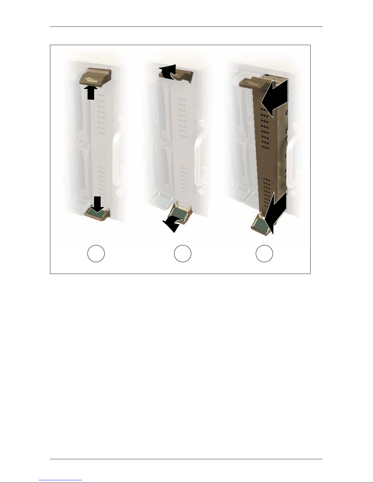
Removing the Dummy Module
Any unused slots in the BX600 S2 or BX600 S3 basic unit are fitted with appropriate dummy modules to comply with the electromagnetic compatibility (EMC)
regulations and ensure sufficient cooling of the system components.
To add a server blade, you must first remove the dummy module from the corresponding slot.
24 Operating Manual BX630 S2
Page 25
Installing the Hardware Installing the Server Blade in the Basic Unit
!
Figure 3: Removing the dummy module for a server blade
Ê Undo the locking mechanism of the handles by pressing the green inside
touch points of the two handles (1). This undoes the locking handles of the
dummy module.
Ê Swivel the top handle upward and the bottom handle downward (2) simulta-
neously until the locking mechanism of the dummy module disengages and
releases the module.
Ê Pull the dummy module completely out of the slot (3).
V CAUTION!
Keep the dummy module for future use. If a server blade is removed
again and not replaced with a new one, the dummy module must be
reinstalled because of cooling, fire protection and EMC regulations.
Install the dummy module in the same way as the server blade as described in
the section below.
BX630 S2 Operating Manual 25
Page 26
Installing the Server Blade in the Basic Unit Installing the Hardware
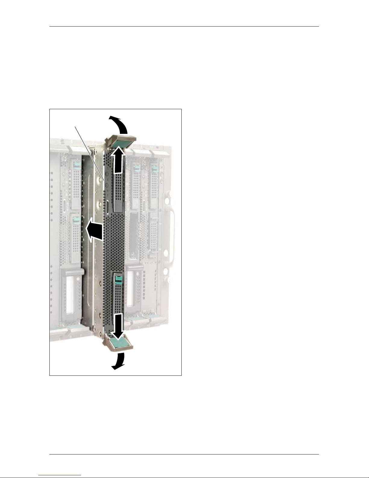
Installing the Server Blade
V CAUTION!
Make sure you observe the safety notes and the information on handling
electrostatic-sensitive devices in the section “Modules with Electrostatic-
Sensitive Devices” on page 19.
I Make sure you install the server
A
2
Ê Undo the locking mechanism of the
1
blade in the correct direction.
The control panel (A) must be at
the top.
handles of the server blade by first
pressing the green inside touch
points of the two handles (1) at the
same time.
Ê Then turn the locking handles
outward (2) into the unlocked
position.
Ê Hold the locking handles in the
© cognitas. Gesellschft für Technik-Dokumentation mbH 2008 Pfad: H:\April\PRIMERGY_Rebranding\von Walte r\bx630_s2_ba\Archiv\bx630s2-ba-en \OBJ_DOKU-2507-002.fm
1
2
Figure 4: Inserting the server blade
unlocked position and push the
server blade as far as possible into
the slot.
26 Operating Manual BX630 S2
Page 27
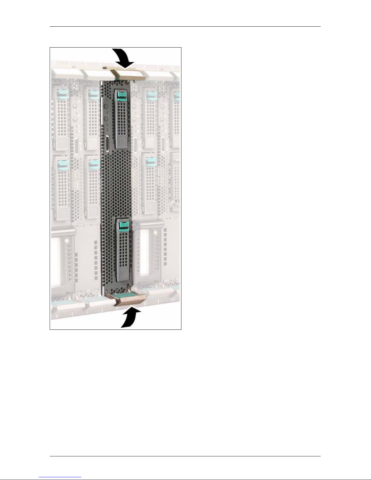
Installing the Hardware Installing the Server Blade in the Basic Unit
Ê Press the locking handles inward
until the locking mechanism
engages fully.
Figure 5: Final engaging of the locking mechanism
Removing the server blade
Remove the server blade in the same way as the dummy module (see
“Removing the Dummy Module” on page 24).
V CAUTION!
If a server blade has been removed and no new blade is installed in its
place, you must install a dummy module in the empty slot.
BX630 S2 Operating Manual 27
Page 28

Connecting Devices Installing the Hardware
4.4 Connecting Devices
All the connections required for operating the BX630 S2 Scalable Server Blade
are made via the midplane of the PRIMERGY BX600 S2 or BX600 S3 basic
unit. When you install the server blade, connections to the infrastructure
modules on the back of the basic unit are made automatically by means of plug
connectors:
– Power supply units
– Management blade(s) for server administration
– KVM blade for connecting a monitor, keyboard and mouse
– Ethernet switch blade(s) and/or pass-thru blades for connecting to the LAN
– Fibre channel switch blades or pass-thru blades for connection to a SAN
(optional, requires installation of an FC daughter card in the server blade,
see Options Guide)
For information on connecting external devices via the infrastructure modules of
the BX600 S2 or BX600 S3 basic unit, see the basic unit operating manual.
© cognitas. Gesellschft für Technik-Dokumentation mbH 2008 Pfad: H:\April\PRIMERGY_Rebranding\von Walte r\bx630_s2_ba\Archiv\bx630s2-ba-en \OBJ_DOKU-2507-002.fm
28 Operating Manual BX630 S2
Page 29

Installing the Hardware Connecting Devices
USB/VGA connection
1
2
A
Figure 6: USB/VGA connectionon on the BX630 S2 server blade and breakout cable
The PRIMERGY BX630 S2 Scalable Server Blade has a USB/VGA connector
on the front (A).. Connecting an external device via the USB/VGA connector
requires a special cable with two USB plugs (2) and a VGA plug (3)..
I The USB/VGA breakout cable is supplied with the basic unit.
For information on connecting external devices via the infrastructure
module of the basic unit, see the operating manual for your basic unit .
BX630 S2 Operating Manual 29
Page 30

© cognitas. Gesellschft für Technik-Dokumentation mbH 2008 Pfad: H:\April\PRIMERGY_Rebranding\von Walte r\bx630_s2_ba\Archiv\bx630s2-ba-en \OBJ_DOKU-2507-002.fm
Page 31

5 Installation and Operation
V CAUTION!
Make sure you observe the safety notes in the chapter “Important notes”
on page 17.
This chapter explains how to set up and operate the BX630 S2 scalable server
blade once you have installed it in the PRIMERGY BX600 S2 or BX600 S3 basic
unit.
– The position and function of the elements on the control and connection
panel of the server blade are described in section 5.1 on page 32.
– The different possible ways of switching the server blade on and off are
described in section 5.2 on page 35.
– Section 5.3 on page 35 explains how to configure the server blade with
ServerView Installation Manager.
– Section 5.4 on page 38 explains how to update the server blade firmware.
BX630 S2 Operating Manual 31
Page 32

Control and Connection Panel Installation and Operation
5.1 Control and Connection Panel
9
8
1
2
3
4
5
6
© cognitas. Gesellschft für Technik-Dokumentation mbH 2008 Pfad: H:\April\PRIMERGY_Rebranding\von Walte r\bx630_s2_ba\Archiv\bx630s2-ba-en \OBJ_DOKU-2508-002.fm
7
Figure 7: Control panel
32 Operating Manual BX630 S2
Page 33

Installation and Operation Control and Connection Panel
1 Voltage/Selection indicator (two-color LED)
Dark: The BX600 S2 or BX600 S3 basic unit is off, 5 V standby voltage
is not present, or the server blade is not installed properly.
Glows green: Server blade is running.
Glows orange: Server blade is off but basic unit is running (5 V standby voltage is
present).
Flashes green: Server blade is switched on and selected for identification, or this
server blade is in a critical state.
Flashes
orange:
Flashes green-
orange
Flashes green-
dark-orange
Server blade is switched off and selected for identification, or this
server blade is in a critical state.
Server blade is in standby mode (ACPI function) or in a critical
state.
Server blade is in standby mode (ACPI function) and selected for
identification, or this server blade is in a critical state.
2 On/Off button fully compatible with the Advanced Configuration Power Interface
(ACPI)
If you press the On/Off button when the BX600 S2 or BX600 S3 basic unit is on (5 V
standby voltage is present) and the server blade is switched off, the power_up
command is sent to the management blade and the server blade is switched on.
If you press the On/Off button for less than 4 seconds when the server blade is
running, the power_off command is sent to the management blade and the server
blade is switched off by the management blade (graceful shutdown).
If you press the On/Off button for more than 4 seconds when the server blade is
running, the server blade is switched off immediately.
3 KVM/MP error indicator (two-color LED)
Dark: KVM has not been activated for this server blade.
Glows green: KVM has been activated for this server blade.
Flashes
orange:
Flashes green-
orange:
4 KVM button (keyboard/video/mouse)
Pressing this button switches the keyboard, monitor and mouse to this server blade.
5 I/O status of the optional I/O module (green LED)
I/O Dark: System is off or signal synchronization has failed.
Green: System is switched on and online.
BX630 S2 Operating Manual 33
KVM has not been activated for this server blade, and this blade
has been deactivated to save energy.
KVM has been activated for this server blade, and this blade has
been deactivated to save energy.
Page 34

Control and Connection Panel Installation and Operation
6 NIC indicator (green LED)
Dark: System or server blade is off and LAN interface is not active.
Glows green: Existing LAN connection.
Flashes green: Active LAN.
7 USB/VGA connector
Connector for adapter cable with two USB ports for external devices (e.g. floppy disk
drive, CD/DVD drive or hard disk drive, mouse or keyboard) and a VGA port.
I A special cable is required! (See figure 6 on page 29)
8 Hard disk access (green LED)
Dark: Hard disk drive not active.
Glows green: Hard disk drive active.
9 Hard disk drive indicator (orange LED)
Dark: No error
Glows orange: Server blade is on and hard disk drive has an error.
Flashes slowly
(1Hz)
Flashes quickly
© cognitas. Gesellschft für Technik-Dokumentation mbH 2008 Pfad: H:\April\PRIMERGY_Rebranding\von Walte r\bx630_s2_ba\Archiv\bx630s2-ba-en \OBJ_DOKU-2508-002.fm
(3Hz)
Reconstruction (RAID message)
Identification of hard disk localization (RAID message)
34 Operating Manual BX630 S2
Page 35

Installation and Operation Switching the Server Blade On/Off
5.2 Switching the Server Blade On/Off
V CAUTION!
If you switch the server blade on and the connected monitor only displays
flickering stripes, switch it off again immediately (see chapter “Trouble-
shooting and Tips” on page 73).
Switching the Server Blade On/Off via the Control Panel
The basic unit must be switched on.
You can switch the server blade on or off using one of the following methods:
– To switch the server blade on, press the On/Off button of the server blade
(position 2 in figure 7 on page 32).
To switch the server blade off, press the On/Off button of the server blade
(position 2 in figure 7 on page 32) for 4 seconds.
– Defined switch-on/switch-off time
The server blade is switched on or off at the time defined in ServerView.
– After power failure
A server blade that was already on when the power failed, automatically
switches on again when power resumes (depending on the BIOS setting,
see section “Power On/Off menu” on page 54??? in chapter “BIOS Setup”
on page 39).
I With the basic unit, you can also switch the installed server blades on an
off via the control panel of the overall system as well as via the Web
interface of the management blade. For detailed information see the
operating manual for your basic unit.
5.3 Configuring the Server Blade
PRIMERGY BX6xx server blades can be set up using one of the following
methods:
– Local installation with or without ServerView Installation Manager
– Remote installation, see the section ServerView Installation Manager Remote
Installation in the ServerView Installation Manager manual on the ServerBooks
DVD.
BX630 S2 Operating Manual 35
Page 36

Configuring the Server Blade Installation and Operation
– Copying the clone images from a remote image repository to the relevant
server blades (for further information see the RemoteDeploy manual on the
ServerBooks DVD (version 5.210 or later)).
I The optional RemoteDeploy software package can be obtained from
the Fujitsu Technology Solutions customer service center
(order number U15000-C286).
Reference Installation
A reference installation of a server blade performed using ServerView Installation
Manager is used as the basis for a clone image. The image is created and then
used by RemoteDeploy for fast installation and configuration of other server
blades.
I For details on using ServerView Installation Manager, see the operating
manual for ServerView Installation Manager on the PRIMERGY
ServerBooks DVD, which is part of the PRIMERGY ServerView Suite
provided with each server system.
Preparing the Hardware
To implement initial installation of the server blade or perform subsequent
© cognitas. Gesellschft für Technik-Dokumentation mbH 2008 Pfad: H:\April\PRIMERGY_Rebranding\von Walte r\bx630_s2_ba\Archiv\bx630s2-ba-en \OBJ_DOKU-2508-002.fm
modifications, you must meet the the following conditions.
– The relevant server blade must be connected to a CD-ROM drive and a
diskette drive via the USB/VGA interface.
– A monitor, a keyboard and a mouse must be connected to KVM blade on the
rear of the BX600 basic unit.
– the relevant server blade must be switched to by pressing the KVM button.
Perform the following steps to prepare the installation of a server blade:
Ê Connect the breakout cable to the USB/VGA port on the front of the relevant
server blade (figure 6 on page 29).
Ê Connect the data cable of the CD-ROM drive and, if required, also the floppy
disk drive to the USB ports of the breakout cable (see figure 6 on page 29).
Ê Make sure that the basic unit is switched on.
Ê To switch the server blade on, press the On/Off button on the control panel
(position 2 in figure 7 on page 32).
Ê If the CD-ROM drive and the floppy disk drive are not supplied with power
via the USB ports of the breakout cable, connect them directly to the mains.
36 Operating Manual BX630 S2
Page 37

Installation and Operation Configuring the Server Blade
Ê Connect the monitor, keyboard and mouse to the KVM blade on the rear of
the basic unit. For information see the BX600 S2 or BX600 S3 basic unit
operating manual.
Ê Press the KVM button (position 4 in figure 7 on page 32) on the control panel
of the server blade to switch the keyboard, mouse and the monitor of the
KVM blade to the server blade.
Preparing the Software
Booting from the CD-ROM drive
Boot the relevant server blade from the ServerView Installation Manager CD to
install the operating system. In some cases this may require that you change a
few settings:
Ê Insert the ServerView Installation Manager CD in the CD-ROM drive and press
the On/Off button (position 2 in figure 7 on page 32) on the control panel of
the server blade.
Ê Press the KVM button (position 4 in figure 7 on page 32) on the control panel
of the server blade to switch the keyboard, mouse and the monitor of the
KVM blade to the server blade. Wait a few seconds for the monitor to be
activated.
Ê When prompted, press [F2] to call up the BIOS setup of the server blade.
Ê In the BIOS setup menu select the Boot submenu and enable Boot from CD-
ROM Drive.
Ê Press [ESC] twice and select Exit Saving Changes from the Exit menu.
Once the server blade has booted from the ServerView Installation Manager CD,
the startup screen is displayed.
BX630 S2 Operating Manual 37
Page 38

Updating the Firmware (BIOS and BMC) Installation and Operation
5.4 Updating the Firmware (BIOS and BMC)
All the files required for updating the server blade components are available
from http://download.ts.fujitsu.com.
You can update both the firmware of the server blade BIOS and the firmware of
the server blade BMC.
I BMC stands for Baseboard Management Controller. The BMC on the
server blade collects management information and sends it to the
management blade.
There are three possible ways of updating the firmware of the server blade
BIOS and the server blade BMC:
– Updating the firmware of the server blade with TFTP.
For detailed information see the operating manual for your basic unit.
– Updating the firmware of the server blade with GlobalFlash.
For detailed information see the GlobalFlash manual.
– Updating the firmware of the server blade from a USB stick.
To update the firmware of the BX630 S2 Server Blade from a USB stick,
© cognitas. Gesellschft für Technik-Dokumentation mbH 2008 Pfad: H:\April\PRIMERGY_Rebranding\von Walte r\bx630_s2_ba\Archiv\bx630s2-ba-en \OBJ_DOKU-2508-002.fm
proceed as follows:
Ê Create a bootable USB stick using the selfextracting USB stick image you
downloaded from http://download.ts.fujitsu.com.
Ê Connect the breakout cable to the relevant server blade. Connect the USB
stick to the other end of the breakout cable.
Ê Switch on the server blade or restart it. The firmware update is performed
automatically.
I You may have to change the order of the boot devices in the BIOS to
enable booting from the USB stick. For further information see the
section “Boot menu” on page 71 chapter BIOS Setup and the
operating manual for ServerView Installation Manager .
38 Operating Manual BX630 S2
Page 39

6 BIOS Setup
In the BIOS Setup you can set the system functions and the hardware configuration of a server blade.
I The scope of the displayed BIOS parameters may differ depending on
the configuration.
The server blade comes with default settings in effect. You can change these
settings in the BIOS Setup menus. Your changes will take effect as soon as you
save the settings and quit the BIOS Setup.
The following lists illustrate the structure of the BIOS Setup menus. The
numbers in brackets refer to the pages on which the individual functions are
described.
Main – Basic system configuration
System Time [46]
System Date [46]
Sync RTC with Mgmt. Blade [46]
POST Errors [46]
SM Error Halt [47]
Boot Diagnostic Screen [47]
Numlock [47]
Boot Menu [47]
Base Memory / Extended Memory [47]
Advanced – Advanced system configuration
Peripheral Configuration [50]
Serial # [50]
Serial Multiplexer [51]
Onboard USB Controller [51]
USB BIOS Legacy Support [51]
Master HD Controller [51]
Slave HD Controller [51]
SAS Option ROM Scan [52]
Master LAN # [52]
Slave LAN # [52]
BX630 S2 Operating Manual 39
Page 40

Master Daughtercard [52]
Slave Daughtercard [52]
Remote Boot [52]
Management LAN [52]
Advanced System Configuration [53]
High Precision Event Timer [53]
Power On/Off [54]
Power off Source [54]
Software [54]
Power Button [54]
Power Failure Recovery [54]
IPMI [56]
SEL Load [56]
BIOS Setup
Clear System Event Log [56]
Event Log Full Mode [56]
System Event Log [57]
Entry Number [57]
Sensor Type[57]
© cognitas. Gesellschft für Technik-Dokumentation mbH 2008 Pfad: H:\April\PRIMERGY_Rebranding\von Walte r\bx630_s2_ba\Archiv\bx630s2-ba-en \OBJ_DOKU-2509-002.fm
Sensor [57]
Event Type [57]
Sensor Event [57]
Event Data [57]
Timestamp [57]
SDRR Browser [57]
SDR Record ID [57]
Entity ID [57]
Entity Inst [57]
SDR ID [58]
Sensor No.[58]
Sensor Type [Units] [58]
Sensor Value[58]
Sensor Value (max)[58]
Sensor Value (min) [58]
Entity ID [58
40 Operating Manual BX630 S2
]
Page 41

BIOS Setup
LAN Settings [58]
DHCP [59]
Local IP Address [59]
Subnet Mask [59]
Gateway Address [59]
Reset Configuration Data [48]
Multiprocessor Specification [49]
Security – Security functions
Supervisor Password [60]
User Password [60]
Set Setup Password [60]
Setup Password Lock [61]
Set System Password [61]
System Password Mode [61]
Setup Prompt [61]
Flash Write [62]
Server – Server management
O/S Boot Timeout [63]
Action [63]
ASR&R Boot Delay (min) [63]
Boot Retry Counter [64]
Temperature Monitoring [64]
CPU Status [65]
Node # (1-4) CPU Status [65]
Re-enable Failed CPUs [66]
Memory Status [67]
Memory Scrubbing [67]
SW Mem Hole Remap [68]
DRAM Bank Interleave [68]
Node Interleave [68]
Memory on Master Board [68]
CPUn (1-4) - DIMMm (1-7) + DIMMm+1 (2-8) [68]
BX630 S2 Operating Manual 41
Page 42

Memory on Slave Board [68]
Re-enable Failed DIMMs [69]
Console Redirection [69]
Port [69]
Baud Rate [69]
Protocol [70]
Flow Control [70]
Console Connection [70]
Mode [70]
# of video pages to support [70]
Boot – System start
Boot priority order [71]
BIOS Setup
CPUn (1-4) - DIMMm (1-7) + DIMMm+1 (2-8) [68]
Excluded from Boot order [72]
Exit – Save settings and terminate BIOS Setup
Save Changes & Exit [72]
© cognitas. Gesellschft für Technik-Dokumentation mbH 2008 Pfad: H:\April\PRIMERGY_Rebranding\von Walte r\bx630_s2_ba\Archiv\bx630s2-ba-en \OBJ_DOKU-2509-002.fm
Discard Changes & Exit [72]
Get Default Values [72]
Load Previous Values [72]
The following sections describe how to call up and use the BIOS Setup as well
as the individual menus and possible settings.
42 Operating Manual BX630 S2
Page 43

BIOS Setup Entering the BIOS Setup
6.1 Entering the BIOS Setup
Ê Start the server blade (cold or warm start).
The subsequent procedure depends on the current setting of the Boot Menu
parameter in the Boot menu (see also section “Boot menu” on page 71):
Boot Menu = Disabled
With this parameter setting, you can open the Main menu.
Boot Menu = Enabled
With this parameter setting, you can open the Main menu or a pop-up
boot menu.
Opening the Main menu
Ê Press the [F2] function key.
Ê Enter the Setup password (if defined) and confirm your entry by pressing
Enter.
Opening the pop-up boot menu
Use this function if you do not want to start your system from the drive that is set
as the first option in the Boot Sequence parameter in the Boot menu.
Ê Press [ESC].
A pop-up boot menu is displayed.
Ê Use the Ê or Ë cursor keys to select the drive from which you want to start
the operating system, and confirm your selection by pressing Enter. The
selection options are the same as the possible settings of the Boot priority
order parameter in the Boot menu.
If a drive is marked with an exclamation mark (!), you cannot select it for
booting.
I The option you select only applies to the current system start. The
next time you start the system, the settings of the Boot Sequence
parameter in the Boot menu will apply again.
Ê To start the BIOS Setup, select the Setup parameter and confirm your
selection with Enter. The Main menu opens and, if applicable, you must
enter and confirm the Setup password.
BX630 S2 Operating Manual 43
Page 44

Operation BIOS Setup
6.2 Operation
1
2
4
3
Figure 8: BIOS Setup screen structure
The BIOS Setup screen is structured as follows:
© cognitas. Gesellschft für Technik-Dokumentation mbH 2008 Pfad: H:\April\PRIMERGY_Rebranding\von Walte r\bx630_s2_ba\Archiv\bx630s2-ba-en \OBJ_DOKU-2509-002.fm
Menu bar (1)
Use the À and  cursor keys to select a menu.
Workspace (2)
The workspace contains the information for the selected menu and the
settings you can make. Use the Ê and Ë cursor keys to select the
parameter whose setting you want to change.
A [Ê] in the left margin indicates that a parameter contains submenus.
To display a submenu, select the relevant parameter and press Enter.
Pressing [ESC] returns you from the submenu to the superordinate
menu.
An asterisk (*) indicates configuration conflicts that must be resolved.
Square brackets ([ ]) enclosing a parameter value indicate that this value
can be changed with the [+] and [-] keys.
Control bar (3)
The control bar shows all the keys you can use to navigate and change
settings in the BIOS Setup.
[F1] Function key for displaying additional information
44 Operating Manual BX630 S2
Page 45

BIOS Setup Operation
[Esc] Function key for quitting a submenu
ÊË Cursor keys for selecting a parameter
ÀÂ Cursor keys for selecting a menu
[+][-] Keys for changing parameter values
Press Enter
Press Enter to perform a menu-dependent action
[F9] Load the default values for all menus
I Pressing the [F7] function key discards all the changes you
have made in this BIOS session and resets the values that
were in effect when you opened the BIOS Setup.
[F10] Save the changed values and quit the BIOS Setup.
Information area (4)
The information area displays brief information on the selected
parameter.
BX630 S2 Operating Manual 45
Page 46

Main menu BIOS Setup
6.3 Main menu
Figure 9: Main menu
© cognitas. Gesellschft für Technik-Dokumentation mbH 2008 Pfad: H:\April\PRIMERGY_Rebranding\von Walte r\bx630_s2_ba\Archiv\bx630s2-ba-en \OBJ_DOKU-2509-002.fm
System Time / System Date
Sets the system time and date.
The system time has the format HH:MM:SS, and the system date has the
format MM/DD/YYYY. Use the tab keys to position the cursor within the
individual input fields.
I If the system time and date are incorrect after you switch the
system off and back on again, the lithium battery is empty and
needs to be replaced.
Sync RTC with Mgmt. Blade
Switches synchronization of the real-time clock with the time of the
management blade on (Enabled) or off (Disabled).
POST Errors
Defines whether the system start is aborted and the system is stopped if
an error is detected.
Halt On All Errors or Enabled
If the self-test detects an error, the system start is aborted and the
system is stopped after the self-test.
46 Operating Manual BX630 S2
Page 47

BIOS Setup Main menu
No Halt On Any Errors or Disabled
The system start is not aborted. If possible, the error is ignored.
SM Error Halt – error handling for system monitoring
Configures the system behavior during the self-test in the event of a
system monitoring error reported by the iRMC (e.g. fan monitoring,
temperature monitoring).
This setting only takes effect if the setting Halt On All Errors is selected
for POST Errors in the Boot Options menu.
Enabled
If the iRMC reports an error to the BIOS, the system start is
aborted and the system is stopped after the self-test.
Disabled
The system start is not aborted if the iRMC reports an error to the
BIOS. The error is only displayed.
Boot Diagnostic Screen
Defines whether the screen displays a logo instead of the start information.
Enabled
The logo is displayed. If an error occurs or if you press the [F3] or
{Esc} key, the display switches to the start information.
Disabled
The start information is displayed on the screen.
Numlock
Defines the setting of the NumLock key after system start.
Auto The state of the NumLock key is not changed.
On The NumLock key is switched on.
Off The NumLock key is switched off.
Boot menu
Defines whether the pop-up Boot menu can be called with the [F12]
function key when the BIOS Setup is called during the POST (Enabled)
or not (Disabled).
Base Memory / Extended Memory
Indicates the size of the available main memory.
BX630 S2 Operating Manual 47
Page 48

Advanced menu BIOS Setup
6.4 Advanced menu
Figure 10: Advanced menu
© cognitas. Gesellschft für Technik-Dokumentation mbH 2008 Pfad: H:\April\PRIMERGY_Rebranding\von Walte r\bx630_s2_ba\Archiv\bx630s2-ba-en \OBJ_DOKU-2509-002.fm
Peripheral Configuration
Calls a submenu for setting up the interfaces and controllers (see section
“Peripheral Configuration” on page 50).
Advanced System Configuration
Calls a submenu for setting the High Precision Event Timer (see section
“Advanced System Configuration” on page 53).
Power On/Off
Calls a submenu for setting the power-on and power-off options of the
server blade (see section “Power On/Off menu” on page 54).
IPMI Calls a submenu with the settings of the Intelligent Platform Management
Interface (see section “IPMI menu” on page 56).
Reset Configuration Data
Defines whether the configuration data is reinitialized when the server
blade is started.
48 Operating Manual BX630 S2
Page 49

BIOS Setup Advanced menu
Yes After the server blade is started, the plug&play functionality
identifies the new configuration data to initialize the installed
boards and drives and resets this field to No. You must enter the
configuration data of non-plug&play components manually.
No After the server blade is started, the plug&play functionality
initializes the installed boards and drives with the configuration
data that is currently in effect. The configuration data of non-
plug&play components is not changed.
Multiprocessor Specification
Sets the version of the multiprocessor table used.
I For compatibility reasons, some operating systems require
version 1.1.
BX630 S2 Operating Manual 49
Page 50

Advanced menu BIOS Setup
6.4.1 Peripheral Configuration
Figure 11: Peripheral Configuration
© cognitas. Gesellschft für Technik-Dokumentation mbH 2008 Pfad: H:\April\PRIMERGY_Rebranding\von Walte r\bx630_s2_ba\Archiv\bx630s2-ba-en \OBJ_DOKU-2509-002.fm
Serial #
Defines how the address and the interrupt of the corresponding serial
interface are configured.
Auto Automatic configuration with an available combination of address
and interrupt.
Disabled
The interface is disabled.
Enabled
User-configured. This setting requires the manual configuration of
the base I/O address and the IRQ in an extra line.
OS Controlled
Operating system configuration.
50 Operating Manual BX630 S2
Page 51

BIOS Setup Advanced menu
Serial Multiplexer
Defines whether the serial interface can be used by the system or by the
iRMC.
System
The serial interface can be used by the system or by the operating
system.
iRMC
The serial interface can be used by the iRMC. The operating
system cannot use the serial interface.
Onboard USB Controller
Defines whether the USB (Universal Serial Bus) controller of the system
board is Enabled or Disabled.
USB BIOS Legacy Support
Defines whether the USB keyboard and mouse emulation is Enabled or
Disabled.
This emulation is also required if you want to start the operating system
from a USB device.
If emulation is enabled, the USB keyboard or the USB mouse can also
be used with operating systems that do not support USB. The operating
system can be started from a USB device if this is also supported by the
operating system.
With emulation disabled, the USB keyboard or mouse can only be used
if supported by the operating system. The operating system cannot be
started from a USB device.
Master HD Controller
Slave HD Controller
Enables or disables the SAS controller on the system board of the master
module or of the slave module of a quad-socket server blade.
Enabled
The SAS controller is enabled.
Disabled
The SAS controller is disabled.
I In a dual-socket server blade, this parameter is not interpreted.
BX630 S2 Operating Manual 51
Page 52

Advanced menu BIOS Setup
SAS Option ROM Scan
Defines whether the SAS BIOS is started by the system BIOS when the
onboard SAS controller is initialized (Enabled) or not (Disabled).
I To be able to start an operating system from an SAS controller,
this controller must be controlled by a BIOS.
Master LAN #
Slave LAN #
Defines whether the onboard LAN controller 1 and/or 2 of the master
module or the slave module of a quad-socket server blade is enabled.
Channel 1 & 2
Channels 1 and 2 of the relevant onboard LAN controller are
enabled.
Channel #
Channel 1 or 2 of the relevant onboard LAN controller is enabled.
Disabled
The relevant onboard LAN controller is disabled.
I For a dual-socket server blade, the parameters Slave LAN 1 and
Slave LAN 2 are not interpreted.
© cognitas. Gesellschft für Technik-Dokumentation mbH 2008 Pfad: H:\April\PRIMERGY_Rebranding\von Walte r\bx630_s2_ba\Archiv\bx630s2-ba-en \OBJ_DOKU-2509-002.fm
Master Daughtercard
Slave Daughtercard
Defines whether the optional I/O daughter card of the master module or
of the slave module of a quad-socket server blade is enabled (Enabled)
or not (Disabled).
I In a dual-socket server blade, the Slave Daughtercard parameter is
not interpreted.
Remote Boot
Defines whether the operating system can be booted via the relevant I/O
daughter card (Enabled) or not (Disabled).
Management LAN
Defines whether the LAN port of the iRMC for remote control of the
system is Enabled or Disabled.
52 Operating Manual BX630 S2
Page 53

BIOS Setup Advanced menu
6.4.2 Advanced System Configuration
Figure 12: Advanced System Configuration
High Precision Event Timer
This option allows you to make the system's high-precision event timer
available to the operating system. This timer is also known as the “multimedia timer“.
Enabled
The operating system can use the timer.
Disabled
The timer is not visible to the operating system.
BX630 S2 Operating Manual 53
Page 54

Advanced menu BIOS Setup
6.4.3 Power On/Off menu
Figure 13: Power On/Off menu
© cognitas. Gesellschft für Technik-Dokumentation mbH 2008 Pfad: H:\April\PRIMERGY_Rebranding\von Walte r\bx630_s2_ba\Archiv\bx630s2-ba-en \OBJ_DOKU-2509-002.fm
Power off Source
Defines how the system can be switched off if the ACPI function is not
enabled.
Software
Defines whether the system can be switched off by a software
program (Enabled) or not (Disabled).
Power Button
Defines whether the system can be switched off via the on/off
button on the front of the system (Enabled) or not (Disabled).
Power Failure Recovery
Defines the system state after the system is restarted due to a power
failure.
Always Off
The system switches on, checks its current state (i.e. initializes
itself) and switches off again.
54 Operating Manual BX630 S2
Page 55

BIOS Setup Advanced menu
I During the brief initialization, all WakeUp sources are recon-
figured, so that the system can be woken via the LAN etc. If this
option is Disabled, the system can only be switched on using the
on/off button.
Always On
The system switches on.
Previous State
The system switches on, checks its current state and returns to
the state it was in before the power failure (ON or OFF).
Disabled
The system does not switch on.
BX630 S2 Operating Manual 55
Page 56

Advanced menu BIOS Setup
6.4.4 IPMI menu
Figure 14: IPMI menu
© cognitas. Gesellschft für Technik-Dokumentation mbH 2008 Pfad: H:\April\PRIMERGY_Rebranding\von Walte r\bx630_s2_ba\Archiv\bx630s2-ba-en \OBJ_DOKU-2509-002.fm
SEL Load
Indicates in percent how full the system event log is.
Clear System Event Log
Defines whether the system event log file is to be cleared the next time
the system is started. All system events and errors are written to this file.
Disabled
The system event log is not deleted.
Enabled
The system event log is deleted the next time the system is
started.
Event Log Full Mode
Defines whether the system event log can be overwritten or not.
Overwrite
If the system event log is full, the oldest entries in each case are
overwritten by new entries.
56 Operating Manual BX630 S2
Page 57

BIOS Setup Advanced menu
Maintain
If the system event log is full, no more entries are written to it. The
system event log must be deleted so that the system can create a
new system event log.
System Event Log
Opens the submenu of the system event log viewer. The system event
log file stores all the events and errors that occur in the system.
Entry Number
Shows the number of the current system event log entry.
You can go to the previous/next entry with the - or + key on the
numeric keypad.
Sensor Type
Shows the sensor type that has triggered the current event.
Sensor
Indicates the sensor that triggered the current event.
Event Type
Indicates the type of the current event.
Sensor Event
Shows the current event in plain text. The data from Event Data are
evaluated for this purpose.
Event Data
Shows the data of the current event as a number code.
Timestamp
Shows the data and time at which the current event occurred.
SDRR Browser
Displays the values of the individual sensor data records. Use the [+] and
[-] keys on the numeric keypad to navigate between the individual
records.
SDR Record ID
Identifier of the sensor data record
Entity ID
Module to which the sensor belongs
Entity Inst
Number of the sensor within the module
BX630 S2 Operating Manual 57
Page 58

Advanced menu BIOS Setup
SDR ID
Sensor type
Sensor No.
Serial number of the sensor
Sensor Type [Units]
Type and unit of the sensor
Sensor Value
Measured value of the sensor
Sensor Value (max)
Maximum permissible sensor value
Sensor Value (min)
Minimum permissible sensor value
LAN Settings
Opens the submenu for the iRMC LAN settings (see section “IPMI LAN
parameters” on page 59).
© cognitas. Gesellschft für Technik-Dokumentation mbH 2008 Pfad: H:\April\PRIMERGY_Rebranding\von Walte r\bx630_s2_ba\Archiv\bx630s2-ba-en \OBJ_DOKU-2509-002.fm
58 Operating Manual BX630 S2
Page 59

BIOS Setup Advanced menu
6.4.4.1 IPMI LAN parameters
Figure 15: IPMI LAN Settings menu
DHCP
Defines whether DHCP support for the iRMC is Enabled or Disabled.
Using the DHCP (Dynamic Host Configuration Protocol) network
protocol, the iRMC can have an IP address assigned to it automatically
by a DHCP server in the network. In this case, you do not have to enter
an IP address manually under Local IP Address.
Local IP Address
Ê Enter the IP address of the system's LAN board, using numeric
characters only.
Subnet Mask
Ê Enter the subnet mask of your LAN segment, using numeric
characters only.
Gateway Address
Ê Enter the gateway address of the system's LAN board, using numeric
characters only.
BX630 S2 Operating Manual 59
Page 60

Security menu BIOS Setup
6.5 Security menu
Figure 16: Security menu
© cognitas. Gesellschft für Technik-Dokumentation mbH 2008 Pfad: H:\April\PRIMERGY_Rebranding\von Walte r\bx630_s2_ba\Archiv\bx630s2-ba-en \OBJ_DOKU-2509-002.fm
Supervisor Password / User Password
Indicates whether a supervisor or user password has been defined
(Installed) or not (Not installed).
Set Supervisor Password
When you press the Enter key, a window is opened in which you can
define the supervisor password. The supervisor password prevents
unauthorized BIOS Setup calls.
To delete an existing supervisor password without defining a new one,
open the password definition window, enter the current password and
press Enter three times.
I Deleting the supervisor password also deletes the user password.
60 Operating Manual BX630 S2
Page 61

BIOS Setup Security menu
Setup Password Lock
Defines the effect of the supervisor password.
I Requirement: A supervisor password must have been defined.
Standard
The supervisor password prevents unauthorized BIOS Setup
calls.
Extended
The supervisor password prevents unauthorized Setup calls and
locks the keyboard during device initialization. This prevents
unauthorized access to settings of installed modules with their
own BIOS.
The BIOS of a module can only be accessed if the supervisor
password is entered during initialization. The user is not prompted
to enter a password.
Set User Password
When you press the Enter key, a window is opened in which you can
define the user password. The user password prevents unauthorized
access to the system.
I Requirement: A supervisor password must have been defined.
System Password Mode
Defines the effect of the user password.
I Requirement: A supervisor password and a user password must
have been defined.
System
After the device is started, the operating system is started. Select
this option if you are using a USB keyboard.
Keyboard
After the device is started, the operating system is started with the
keyboard and mouse locked. This lock is released by entering the
user password. A prompt to enter a password is not displayed.
Setup Prompt
Defines whether the Setup prompt is displayed during system start
(Enabled) or not (Disabled).
BX630 S2 Operating Manual 61
Page 62

Security menu BIOS Setup
Flash Write
Defines whether the system BIOS is write-protected.
Enabled
The system BIOS can be written to or deleted.
Disabled
The system BIOS cannot be written to or deleted.
© cognitas. Gesellschft für Technik-Dokumentation mbH 2008 Pfad: H:\April\PRIMERGY_Rebranding\von Walte r\bx630_s2_ba\Archiv\bx630s2-ba-en \OBJ_DOKU-2509-002.fm
62 Operating Manual BX630 S2
Page 63

BIOS Setup Server menu
6.6 Server menu
Figure 17: Server menu
O/S Boot Timeout
Defines whether the system is restarted (Enabled) or not (Disabled) if the
operating system cannot establish a connection to a server management
process within a defined period of time. In this case, the server
management firmware assumes a system startup error.
I If the operating system has no server management process, you
must set this parameter to Disabled to prevent the server
management firmware from initiating a restart by mistake. The
watchdog timer and the server management process (agent) are
installed with ServerView.
Action
Defines the behavior following an OS Boot Timeout (Continue - No
Action; Reset; Power cycle).
ASR&R Boot Delay (min)
Defines the delay of the system restart after a shutdown due to an error
(1 - 30 minutes). The restart occurs after the set waiting time has
elapsed.
BX630 S2 Operating Manual 63
Page 64

Server menu BIOS Setup
Boot Retry Counter
Defines the maximum number of attempts (0-7) to start the operating
system. This parameter depends on the setting of the O/S Boot Timeout
parameter on the one hand. On the other hand, other critical system
errors can lead to a restart of the system and thus to a decrease in the
counter value. After the last attempt, the system is finally shut down, or,
if configured, the diagnostic system is started.
Temperature Monitoring
Defines whether the system is shut down (Enabled) or not (Disabled) if the
ambient temperature or a processor's temperature rises above a critical
point.
If the operating system has an active server management process, this
monitors the temperatures and shuts down the system if critical temperature values occur.
After a shutdown, the system restarts after the period of time defined for
the ASR&R Boot Delay parameter and depending on the Boot Retry
Counter parameter.
CPU Status
Opens a submenu for setting the CPU status (see section “CPU Status”
on page 65).
© cognitas. Gesellschft für Technik-Dokumentation mbH 2008 Pfad: H:\April\PRIMERGY_Rebranding\von Walte r\bx630_s2_ba\Archiv\bx630s2-ba-en \OBJ_DOKU-2509-002.fm
Memory Status
Opens a submenu for setting the memory status (see section “Memory
Status” on page 67).
Console Redirection
Opens a submenu for setting up terminal communication (see section
“Console Redirection” on page 69).
64 Operating Manual BX630 S2
Page 65

BIOS Setup Server menu
6.6.1 CPU Status
Figure 18: CPU Status
Node # CPU Status
Defines whether the selected CPU is used or not. You should only
disable a CPU if it has reported an internal error. The error is recorded in
the system event log, which you can view with the SCU (Server Configuration Utility) or the RemoteView or ServerView programs.
Failed
The CPU cannot be used by the operating system. As long as the
status is Failed, an entry is written to the system event log each
time the system is started.
Disabled
The CPU cannot be used by the operating system.
Enabled
The CPU can be used by the operating system.
I If there is only one CPU, this parameter has no effect. This CPU
is always used when the system is started. Also if four CPUs are
installed and none of them are set to Enabled, the first CPU is
used.
BX630 S2 Operating Manual 65
Page 66

Server menu BIOS Setup
Even if only one CPU is installed, the status indicators are
displayed for all possible CPUs. If Disabled is set for all the CPUs,
the system still starts with one CPU.
Re-enable Failed CPUs
Resets all CPUs flagged as Failed to Enabled.
© cognitas. Gesellschft für Technik-Dokumentation mbH 2008 Pfad: H:\April\PRIMERGY_Rebranding\von Walte r\bx630_s2_ba\Archiv\bx630s2-ba-en \OBJ_DOKU-2509-002.fm
66 Operating Manual BX630 S2
Page 67

BIOS Setup Server menu
6.6.2 Memory Status
Figure 19: Memory Status
Memory Scrubbing
Specifies whether memory will be screened and one-bit errors
recovered. This involves the reading and restoration of the constant
memory. This process recovers one-bit memory errors and prevents
most multibit memory errors, since the latter are due to an accumulation
of one-bit memory errors.
I The cause of one-bit memory errors may be inappropriate or
incorrect system environment specifications.
Enabled
One-bit memory errors are corrected.
Disabled
One-bit errors are not corrected. System performance is
enhanced.
BX630 S2 Operating Manual 67
Page 68

Server menu BIOS Setup
SW Mem Hole Remap
Defines whether the address space required for the PCI configuration is
regained or not.
Enabled
For main memory larger than 3 Gbytes, the main memory area
above 4 Gbytes that is hidden by the PCI devices is shown again.
This setting affects the performance but may increase the
available memory drastically. This option has no effect for a fully-
configured main memory.
Disabled
For main memory larger than 3 Gbytes, the main memory area
that is hidden by the PCI devices is not used. This increases the
performance.
DRAM Bank Interleave
Enables a memory bank to be addressed within the main memory of a
CPU (node) while data is read from or written to another memory bank.
To allow this bank interleaving, the relevant memory banks must be fitted
with memory modules of the same capacity. Possible settings: Auto
(default) and Disabled.
Node Interleave
© cognitas. Gesellschft für Technik-Dokumentation mbH 2008 Pfad: H:\April\PRIMERGY_Rebranding\von Walte r\bx630_s2_ba\Archiv\bx630s2-ba-en \OBJ_DOKU-2509-002.fm
Enables a memory bank to be addressed across nodes while data is
read from or written to another memory bank. To allow this node
interleaving, the relevant memory banks must be fitted with memory
modules of the same capacity. Possible settings: Auto (default) and
Disabled.
CPUn - DIMMm + DIMMm+1
Sets the status of the corresponding memory module:
Failed
As long as at least one error-free bank is available, the memory
module is no longer used by the system because a non-
correctable error or too many correctable errors have occurred.
Once you have replaced a defective memory module, you must
reset this parameter to Enabled. As long as the module status is
Failed, an entry is automatically written to the system event log
each time the system is started.
Disabled
The memory module is not used by the system.
68 Operating Manual BX630 S2
Page 69

BIOS Setup Server menu
Enabled
If the bank is fitted, the memory module is used by the system.
Re-enable Failed DIMMs
Resets all memory modules flagged as Failed to Enabled.
6.6.3 Console Redirection
Figure 20: Console Redirection menu
Port
Defines the port used for communication with the terminal (Serial # or
Disabled). The Disabled setting switches off the terminal functionality and
makes the other parameters described in this section disappear.
Baud Rate:
Requirement: The Port field must not be set to Disabled.
Defines the transfer speed used for communication with the terminal.
This setting must be the same both on the terminal and on the server.
300, 1200, 2400, 9600, 19.2K, 38.4K, 57.6K, 115.2K
The data is transferred to the terminal at the selected transfer rate.
BX630 S2 Operating Manual 69
Page 70

Server menu BIOS Setup
Protocol
Defines the transmission protocol used for communication with the
terminal. This setting should be the same on both the terminal and the
server. The protocols differ in the supported key sequences and
character sets and whether they can display color or only black and
white.
Flow Control
Defines how transfer via the port is controlled.
This setting must be the same on both the terminal and the server.
Requirement: The Port parameter must not be set to Disabled.
Console connection
Opens the submenu in which you make the settings for operating a
terminal on the system. The terminal can be connected to the server
using a direct serial connection (null modem cable). Screen output is
displayed in parallel on the terminal and on the system monitor.
Keyboard input on the terminal is sent to the system and handled in the
same way as input made on the connected server keyboard. You can, for
example, open and modify the BIOS Setup of the system on the terminal.
Enabled
The function is enabled.
© cognitas. Gesellschft für Technik-Dokumentation mbH 2008 Pfad: H:\April\PRIMERGY_Rebranding\von Walte r\bx630_s2_ba\Archiv\bx630s2-ba-en \OBJ_DOKU-2509-002.fm
Disabled
The function is disabled.
I You cannot enter a system password at the terminal in keyboard
mode.
Mode
Defines how long the terminal connection is available. Requirement: The
Port parameter must not be set to Disabled.
Standard
The terminal connection is only available during system startup.
Enhanced
The terminal connection is also available after system start.
# of video pages to support
Defines the number of video pages to allocate for console redirection.
70 Operating Manual BX630 S2
Page 71

BIOS Setup Boot menu
6.7 Boot menu
Figure 21: Boot menu
Boot priority order
Defines the order in which the listed devices are searched for the system
files that the system BIOS requires for booting.
Note:
– Use the Êand Ë keys to select a device.
– Use the [+] and [-] keys to move the selected device up or down in the
list.
– Use the [f] and [r] keys to mark the selected device as fixed or
removable.
– Use the [x] key to add a device to the list of bootable devices or to
remove it from the list.
– You can release or lock the selected device for booting with the key
combination [Shift][1]. A locked device is flagged with an exclamation
mark at the beginning of the line.
– Use the [1] - [4] keys to load the default boot order.
BX630 S2 Operating Manual 71
Page 72

Exit menu BIOS Setup
Excluded from Boot order
Defines the list of devices that are excluded from the boot order.
6.8 Exit menu
© cognitas. Gesellschft für Technik-Dokumentation mbH 2008 Pfad: H:\April\PRIMERGY_Rebranding\von Walte r\bx630_s2_ba\Archiv\bx630s2-ba-en \OBJ_DOKU-2509-002.fm
Figure 22: Exit menu
Save Changes & Exit
Saves parameter changes and terminates the BIOS Setup.
Discard Changes & Exit
Discards parameter changes and terminates the BIOS Setup.
Get Default Values
Resets all the parameters to their default values.
Load Previous Values
Resets all the parameters to the values that were in effect when the BIOS
Setup was called up.
72 Operating Manual BX630 S2
Page 73

7 Troubleshooting and Tips
V CAUTION!
Make sure you observe the safety notes in the chapter “Important notes”
on page 17.
How to handle errors that may occur while operating server blades in the basic
unit is described in the BX600 S2 or BX600 S3 basic unit operating manual.
If a fault occurs, try to correct it as described
– in the chapter "Troubleshooting and Tips" in the BX600 S2 or BX600 S3
basic unit operating manual,
– in the chapters for the installed components,
– in the documentation for the connected devices,
– in the help systems of the individual programs used.
If you are unable to correct the problem, proceed as follows:
Ê Make a note of the steps you have taken and the situation in which the fault
occurred. Also make a note of the error messages displayed.
Ê Switch off the defective server blade or the system.
Ê Contact customer service.
BX630 S2 Operating Manual 73
Page 74

© cognitas. Gesellschft für Technik-Dokumentation mbH 2008 Pfad: H:\April\PRIMERGY_Rebranding\von Walte r\bx630_s2_ba\Archiv\bx630s2-ba-en \OBJ_DOKU-2510-002.fm
Page 75

8 Hot-plug components
This chapter describes how to replace or add hot-plug components in the
PRIMERGY BX630 S2 scalable server blade.
V CAUTION
Only hard disk modules can be added or replaced while the system is
running. For all other system components, the server blade must be
switched off and removed from the basic unit in order to open it. The
required procedure is described in the Options Guide or the Service
Supplement and must only be performed by qualified staff.
8.1 Hot-plug disk drives
In a PRIMERGY BX630 S2 dual-socket server blade, you can install one or two
2.5-inch SAS or SATA-II hard disk drives. In the BX630 S2 quad-socket server
blade, you can install up to four hard disk drives.
I You cannot operate both SAS and SATA hard disks together in a server
blade.
On delivery, the available hard disk drives for the BX630 S2 server blade are
mounted in a module frame that allows you to replace defective drives and add
new ones while the system is running. Together, the hard disk drive and the
module frame make up the hard disk module.
V CAUTION!
● A hard disk must only be removed from the module by a service
technician.
● The hard disk modules (drives) must all be clearly marked, so that
they can be reinstalled in the original bays if they are removed. If you
mix up the hard disks you might lose existing data.
● "Hot plugging" is only possible in conjunction with a corresponding
RAID configuration.
For more information on RAID configurations or RAID levels, see the
documentation for the RAID controller.
BX630 S2 Operating Manual 75
Page 76

Hot-plug disk drives Hot-plug components
Figure 23: 2.5-inch hard disk module and dummy module
1 Hard disk module (hard disk carrier with installed hard disk drive)
2 Indicators
HDD Busy (LED green)
HDD Fault (LED orange)
For a description, see the table on page 33 in the section „Control and
Connection Panel“.
© cognitas. Gesellschft für Technik-Dokumentation mbH 2008 Pfad: H:\April\PRIMERGY_Rebranding\von Walte r\bx630_s2_ba\Archiv\bx630s2-ba-en \OBJ_DOKU-2511-002.fm
3 Handle for engaging and disengaging the hard disk module
4 Locking button
5 Indentation for a sticker with the current drive identifier
6 Dummy module
7 Locking tabs
76 Operating Manual BX630 S2
Page 77

Hot-plug components Handling hard disk drives and HDD modules
8.2 Handling hard disk drives and HDD
modules
Hard disk drives incorporated in the HDD modules are highly sensitive electromagnetic devices and must be handled with great care. Incorrect handling can
cause partial or total failure of the hard disk drives. These failures can result in
data errors and to a loss of data or to total corruption of the hard disk drive.
Observe the following rules to prevent such problems occurring:
● Only store and transport HDD modules within the limits stipulated in the
specification.
● When transporting HDD modules (even over short distances), always use
the original packaging (ESD label).
● Never expose HDD modules to a temperature shock. Avoid the formation of
condensation inside and on the outside of the hard disk drive.
V CAUTION!
The HDD module must be acclimatized in its operating environment
for an acclimatization time before it is started up for the first time.
Temperature difference (°C)
(operating environment/
Table 1: Acclimatization times for HDD modules
Minimum acclimatization time
(hours)
outside)
53
10 5
15 7
20 8
25 9
30 10
● Always set the HDD module down carefully, with the large surface facing
downwards to prevent it from tipping over.
BX630 S2 Operating Manual 77
Page 78

Installing/removing the dummy module Hot-plug components
8.3 Installing/removing the dummy module
Unused bays are fitted with a dummy module. Remove the dummy module
before you install an additional hard disk module.
1
2
© cognitas. Gesellschft für Technik-Dokumentation mbH 2008 Pfad: H:\April\PRIMERGY_Rebranding\von Walte r\bx630_s2_ba\Archiv\bx630s2-ba-en \OBJ_DOKU-2511-002.fm
Figure 24: Removing the dummy module
Ê Press the two tabs on the dummy module together until the lock is
released (1).
Ê Remove the memory module from the slot (2).
To install the dummy module, follow the above procedure in reverse.
1
V CAUTION!
Keep the dummy module for future use. If you have removed the hard
disk module and do not replace it with a new one, you must reinstall the
dummy module to comply with EMC (electromagnetic compatibility)
regulations and cooling and fire protection requirements. Make sure that
the dummy module engages properly in the bay.
78 Operating Manual BX630 S2
Page 79

Hot-plug components Installing/removing a hard disk module
8.4 Installing/removing a hard disk module
Unlocking the hard disk module
2
1
Figure 25: Unlocking a 2.5-inch hard disk module
– Press the green locking lever to the left (1) and swivel the locking handhold
to the front (2).
BX630 S2 Operating Manual 79
Page 80

Installing/removing a hard disk module Hot-plug components
Installing a hard disk module
Figure 26: Installing a hard disk module
Ê Carefully push the hard disk module into the empty bay as far as it will go.
© cognitas. Gesellschft für Technik-Dokumentation mbH 2008 Pfad: H:\April\PRIMERGY_Rebranding\von Walte r\bx630_s2_ba\Archiv\bx630s2-ba-en \OBJ_DOKU-2511-002.fm
Ê Swivel the handle fully round in the direction of the arrow until the locking
mechanism engages.
Removing the hard disk module
V CAUTION!
● Only remove a HDD module during operation if the drive is not
currently being accessed. Observe the control LEDs for the corresponding HDD modules (see “Control and Connection Panel” on
page 32).
● Under no circumstances should you remove an HDD module while
the system is in operation if you are not sure whether the hard disk
drive is operated by a RAID controller and belongs to a disk array
which is operating at RAID level 1.
An HDD module can only be replaced during operation in conjunction
with a corresponding RAID configuration.
80 Operating Manual BX630 S2
Page 81

Hot-plug components Installing/removing a hard disk module
● All HDD modules (drives) must be uniquely identified so that they can
be reinstalled in their original mounting locations later. If this is not
done, existing data can be lost.
If you want to remove an HDD module during operation, proceed as follows:
Ê If you want to remove a HDD module that is not defective, the drive must be
first set to offline via the software (RAID controller configuration software).
Ê Unlock the HDD module as described in section “Unlocking the hard disk
module” on page 79.
Ê Pull the HDD module out a few centimeters.
Ê Wait for at least 60 seconds.
I This period is necessary for the RAID controller to recognize that an
HDD module has been removed and for the hard disk drive to come
to a stop.
Ê Pull the HDD module out completely.
Ê Install the new HDD module, as described in “Unlocking the hard disk
module” on page 79 and “Installing a hard disk module” on page 80.
V CAUTION!
If you have removed an HDD module and do not install a new one in
its place, put the dummy module back in its place for cooling, to
comply with EMC regulations (regulations regarding electromagnetic
compatibility), and for protection against fire. Ensure that the dummy
module engages correctly in the slot.
BX630 S2 Operating Manual 81
Page 82

© cognitas. Gesellschft für Technik-Dokumentation mbH 2008 Pfad: H:\April\PRIMERGY_Rebranding\von Walte r\bx630_s2_ba\Archiv\bx630s2-ba-en \OBJ_DOKU-2511-002.fm
Page 83

Abbreviations
ASR&R
Automatic Server Reconfiguration and Restart
ATA
Advanced Technology Attachment
BIOS
Basic Input-Output System
CD
Compact Disk
COM
Communication
CPU
Central Processing Unit
DBMS
DC
DDR
DIMM
DVD
ECC
EDC
Database Management System
Dual Core
Double Data Rate (RAM)
Dual Inline Memory Module
Digital Versatile Disk
Error Correcting Code
Error Detection Code
BX630 S2 Operating Manual 83
Page 84

Abbreviations
EMC
Electromagnetic Compatibility
ESD
Electrostatic Discharge
FBD
Fully Buffered DIMMs
FC
Fibre Channel
FSB
Front Side Bus
GAM
Global Array Manager
HDD
Hard Disk Drive
HU
© cognitas. Gesellschft für Technik-Dokumentation mbH 2008 Pfad: H:\April\PRIMERGY_Rebranding\von Walte r\bx630_s2_ba\Archiv\bx630s2-ba-en \OBJ_DOKU-2535-002.fm
Height Unit
I/O
Input/Output
ID
Identification
IDE
Integrated Drive Electronics
IP
Internet Protocol
iSCSI
Internet Small Computer System Interface over IP
LAN
Local Area Network
84 Operating Manual BX630 S2
Page 85

LCD
LED
MRL
NIC
NMI
PCI
Abbreviations
Liquid Crystal Display
Light-Emitting Diode
Manually Retention Latch
Network Interface Card
Non Maskable Interrupt
Peripheral Component Interconnect
PDA
POST
PSU
RAID
ROM
SAN
SAS
Prefailure Detection and Analyzing
Power On Self Test
Power Supply Unit
Redundant Arrays of Independent Disks
Read-Only Memory
Storage Area Network
Serial Attached SCSI
SATA
Serial Advanced Technology Attachment
BX630 S2 Operating Manual 85
Page 86

Abbreviations
SCA
Single Connector Attachment
SCSI
Small Computer System Interface
SCU
Server Configuration Utility
SFP
Small Form Factor Pluggable
TOE
TCP/IP Offload Engine
USB
Universal Serial Bus
VGA
Video Graphics Adapter
VPD
© cognitas. Gesellschft für Technik-Dokumentation mbH 2008 Pfad: H:\April\PRIMERGY_Rebranding\von Walte r\bx630_s2_ba\Archiv\bx630s2-ba-en \OBJ_DOKU-2535-002.fm
Vital Product Data
WOL
Wakeup on LAN
86 Operating Manual BX630 S2
Page 87

Index
A
acclimatization time 77
ambient conditions 14
ASR&R 10
availability 10
B
BIOS setup 39
Advanced menu 48
Advanced menu, Advanced
System Configuration 53
Advanced menu, IPMI
settings 56
Advanced menu, Peripheral
Configuration 50
Advanced menu, Power On/Off
settings 54
Boot menu 71
Exit menu 72
Main menu 46
operation 44
Security menu 60
Server menu 63
Server menu, CPU Status 65
Server menu, Memory Status 67
Server menu, terminal
functionality 69
start 43
BIOS update 11
C
CE marking 13, 20
certification
product safety 13
compliance standards 13
configure
server blade 11
consumables 20
CPU 8
D
data manipulation 5
delivery note 23
disposal, devices 21
dummy module
install 24
server blade 24
dummy module, hard disk
module 78
dummy module, HDD module 81
E
ECC 10
electrical specifications 13
electromagnetic compatibility 13, 20
electrostatic-sensitive devices
(ESD) 19
EMC directive 13
EMC regulations 78, 81
environment class 14
environmental protection 20
Error Correcting Code 10
ESD (electrostatic-sensitive
devices) 19
F
Fibre Channel 9
firmware 38
update 38
flash-EPROM 11
H
hard disk drive
acclimatization time 77
dummy module 75
handling 75, 77
install 75
install/remove 79
module frame 75, 79
replacing online 81
BX630 S2 Operating Manual 87
Page 88

Index
I
I/O module 9
information material, additional 7
install
dummy module 24
hard disk drives 75
installation procedure, overview 15
security functions 5
server blade
ambient conditions 14
compliance standards 13
control panel 32
CPU 8
dimensions 14
dummy module 24
K
KVM button 33
electrical specifications 13
hard disk drives 75
indicators 32
L
labels 21
lithium battery 18
Low Voltage Directive 13, 20
memory 8
safety standards 13
technical data 13
ventilation space 14
weight 14
M
meaning of the symbols 12
memory
SDRAM 8
N
norms and standards 13
© cognitas. Gesellschft für Technik-Dokumentation mbH 2008 Pfad: H:\April\PRIMERGY_Rebranding\von Walte r\bx630_s2_ba\Archiv\bx630s2-ba-en \OBJ_DOKU-2540-002.fm
notational conventions 12
notes on safety 17
server management 10
ServerView
10
supported functions 10
ServerView Installation Manager 11
reference installation 36
switch off
system 35
switch on
system 35
O
On/Off button 33
overloading 10
switch-off time
define 35
switch-on time
define 35
P
packaging 20, 23
PDA 10
processor 8
system
switch off 35
switch on 35
unpacking 23
R
RAID level 10
recycling devices 21
reliability 10
replacing online 81
return of devices 21
S
safety standards 13
saving energy 20
88 Operating Manual BX630 S2
T
target group 6
technical data 13
transport damage 23
troubleshooting and tips 73
type label 23
Page 89

U
unpacking
system 23
update
BIOS 38
BMC 38
firmware 38
USB/VGA connector 34
V
ventilation space 14
W
weight 14
Index
BX630 S2 Operating Manual 89
Page 90

© cognitas. Gesellschft für Technik-Dokumentation mbH 2008 Pfad: H:\April\PRIMERGY_Rebranding\von Walte r\bx630_s2_ba\Archiv\bx630s2-ba-en \OBJ_DOKU-2540-002.fm
 Loading...