

Page 1

SPLIT TYPE
ROOM AIR CONDITIONER
WALL MOUNTED TYPE
CONTENTS
SPECIFICATIONS. . . . . . . . . . . . . . . . . . .
1
DIMENSIONS . . . . . . . . . . . . . . . . . . . . . .
2
REFRIGERANT SYSTEM DIAGRAM. . . .
3
CIRCUIT DIAGRAM . . . . . . . . . . . . . . . . .
4
ERROR DETECTION . . . . . . . . . . . . . . .
5
INDOOR PCB CIRCUIT DIAGRAM . . . . .
9
OUTDOOR PCB CIRCUIT DIAGRAM . . .
11
PARTS (INDOOR UNIT) . . . . . . . . . . . . .
13
PARTS (OUTDOOR UNIT) . . . . . . . . . . .
18
21
ACCESSORIES . . . . . . . . . . . . . . . . . . .
Indoor unit Outdoor unit
ASYG09LTCB AOYG09LTCN
Page 2
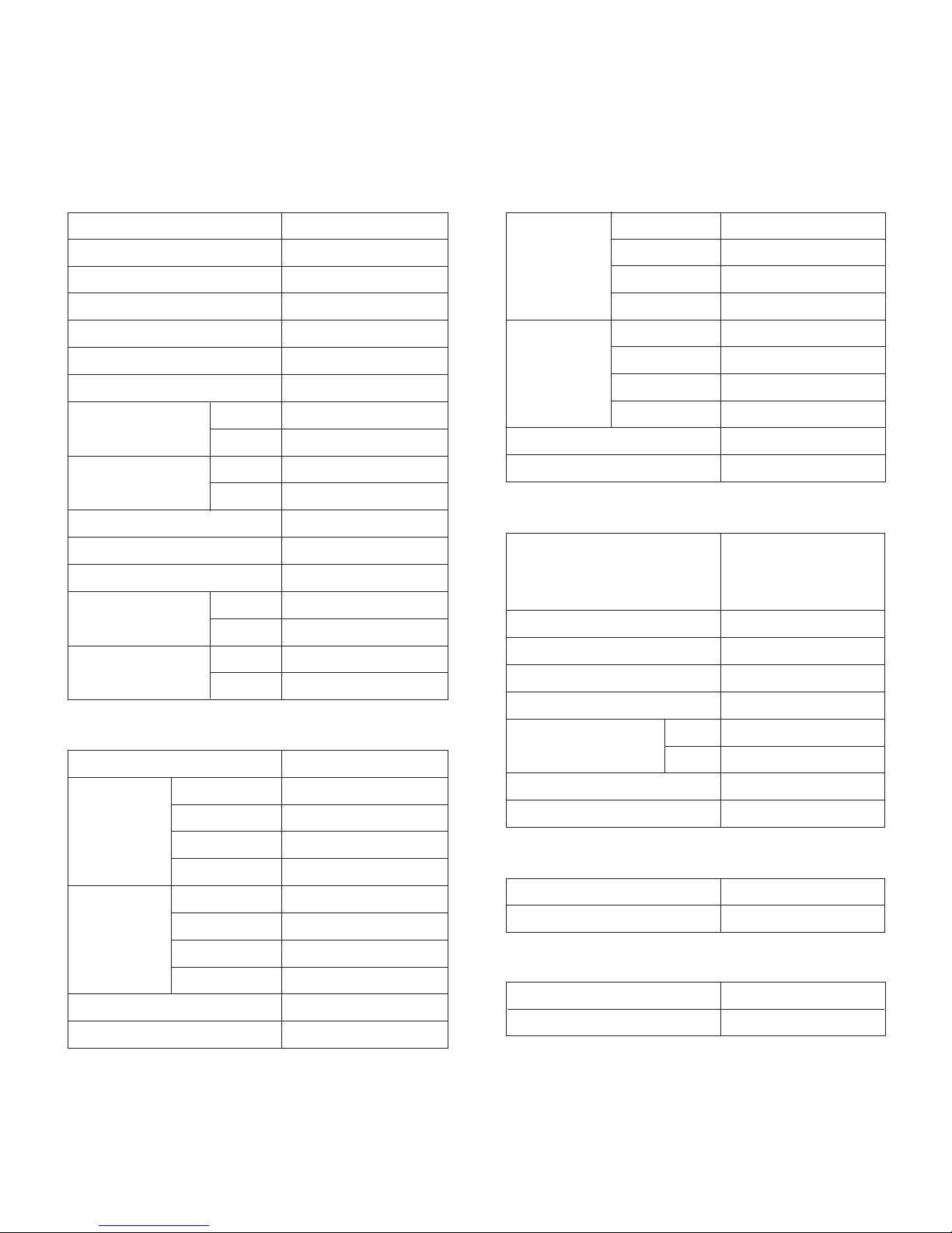
SPECIFICATIONS
TYPE Cool & heat inverter
INDOOR UNIT ASYG09LTCB
OUTDOOR UNIT
AOYG09LTCN
COOLING CAPACITY
2.50 kW
HEATING CAPACITY
3.20 kW
POWER SOURCE
230 V
FREQUENCY 50 Hz
RUNNING
CURRENT
MAXIMUM
CURRENT
2.6 A
3.3 A
INPUT
WATTS
0.505 kW
0.66 kW
E.E.R. Cooling 4.95 kW/kW
COP
Heating
Cooling
Heating
Cooling
Heating
Cooling
Heating
Cooling
Heating
4.85 kW/kW
MOISTURE REMOVAL
AIR CIRCULATION
HIGH
6.5 A
9.0 A
1.3 L/h
800 m3/h
800 m3/h
FAN MOTOR
POWER SOURCE
230 V
High speed
INDOOR
UNIT
Cooling
Medium speed
Low speed
Quiet
High speed
INDOOR
UNIT
Heating
Medium speed
Low speed
Quiet
High speed
Medium speed
Low speed
Quiet
1,300 r.p.m.
1,080 r.p.m.
960 r.p.m.
650 r.p.m.
1,300 r.p.m.
1,120 r.p.m.
960 r.p.m.
650 r.p.m.
OUTDOOR UNIT Heating 750 r.p.m.
OUTDOOR UNIT Cooling 750 r.p.m.
ELECTRICAL DATA
INDOOR
UNIT
Cooling
High speed
Medium speed
Low speed
Quiet
INDOOR
UNIT
Heating
OUTDOOR UNIT Heating
NOISE LEVEL
improper
42 dB
36 dB
32 dB
21 dB
42 dB
37 dB
32 dB
21 dB
50 dB
OUTDOOR UNIT Cooling 50 dB
2011.09.12 1
COMPRESSOR TYPE
Hermetic type,
4 pole, 3 phase,
DC inverter motor,
Rotary
DISCRIMINATION DA89X1C-20FZ2
PRECHARGED REFRIGERANT
REFRIGERANT TYPE
R410A
1,050 g
1,050 g
WEIGHT (with oil)
9.2 kg
COMPRESSOR AND REFRIGERANT
Pipe length
15 m
FULL CHARGE
20 m 1,150 g
MAXIMUM PIPING HEIGHT
15m
ADDITIONAL CHARGE
20 g/m
WEIGHT
INDOOR UNIT Shipping / Net
Shipping / Net
12 kg / 9.5 kg
OUTDOOR UNIT
39 kg / 36 kg
INDOOR UNIT H x W x D
H x W x D
282 x 870 x 185 mm
OUTDOOR UNIT
540 x 790 x 290 mm
DIMENSIONS
Page 3
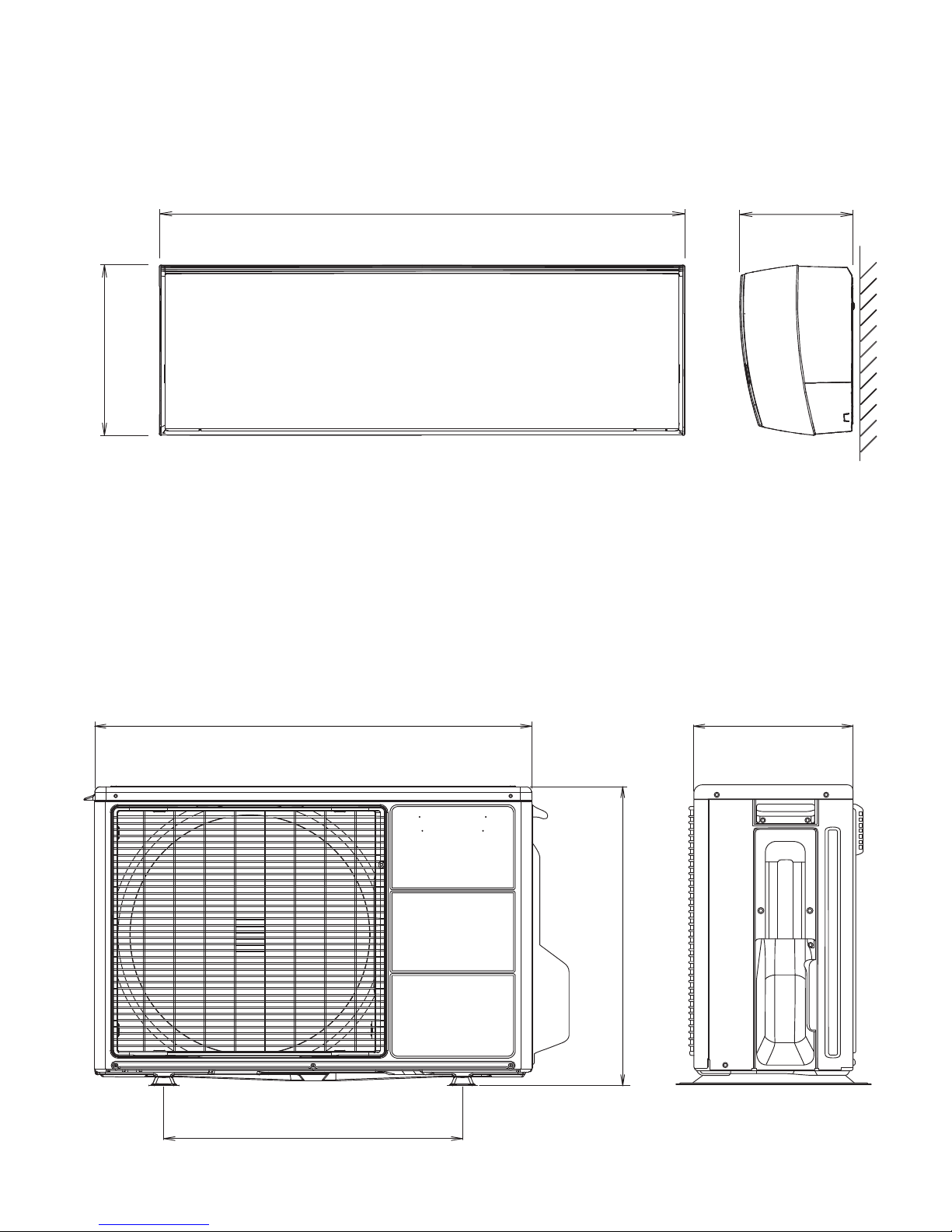
DIMENSIONS
unit : mm
282
185
870
2011.09.12 2
INDOOR UNIT
Drain hose length
600 mm
Drain pipe diameter
Inside : 14.2 mm
Outside : 16.2 mm
OUTDOOR UNIT
540
290790
540
Page 4

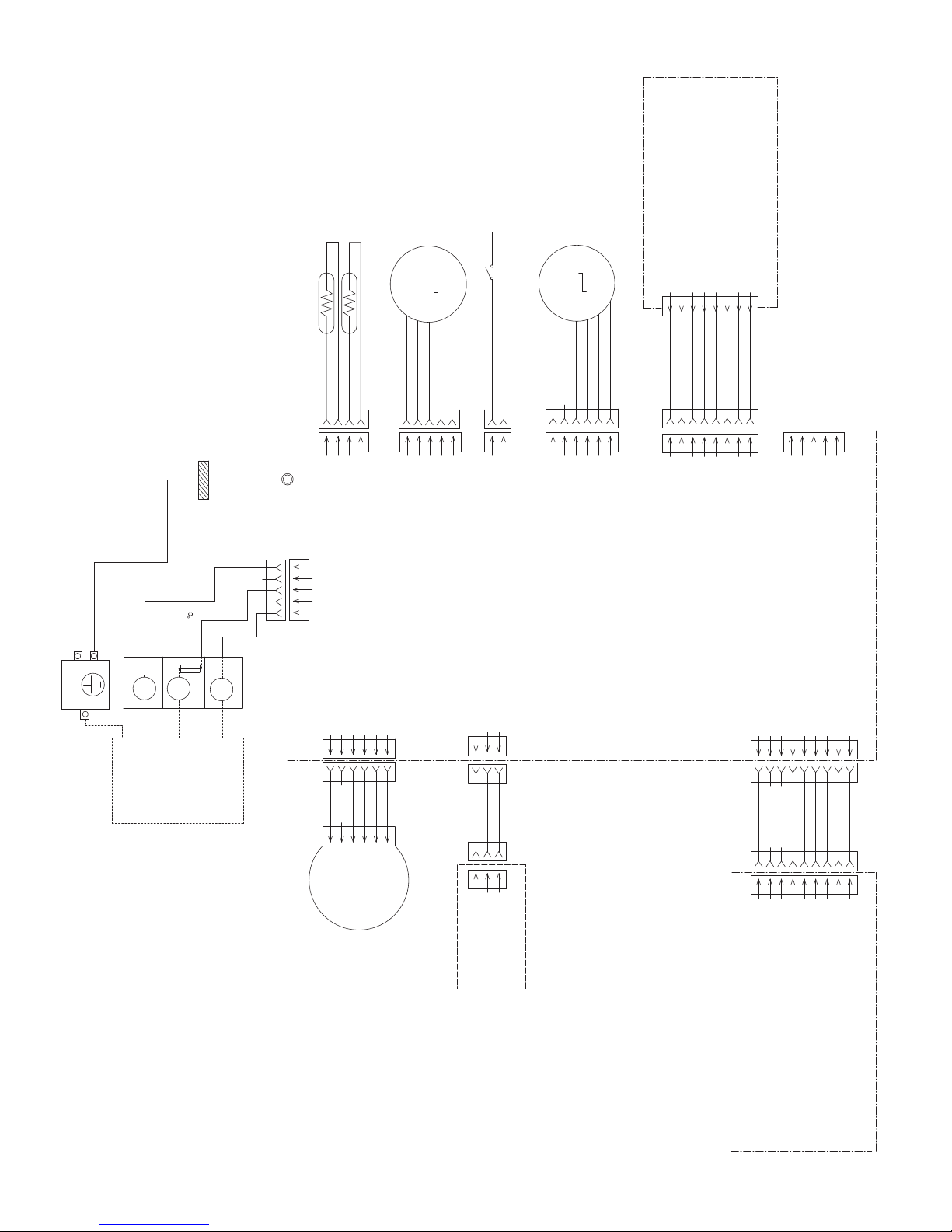
REFRIGERANT
SYSTEM DIAGRAM
2-way valve
Strainer
Strainer
3-way valve
Muffler
4-way valve
Expansion valve
Refrigerant direction
Heat exchanger
(indoor unit)
Heat exchanger
(outdoor unit)
Compressor
Cooling
Heating
Refrigerant pipe diameter
Liquid : 1/4" (6.35 mm)
Gas : 3/8" (9.52 mm)
2011.09.12 3
Page 5

REACTOR
W10
COMPRESSOR
FAN MOTOR
EXPANSION
VALV E
4-WAY VALVE
HEATER
THERMOSTAT ( 55 )
FUSE 250V 5A x 2
FUSE 250V 20A
FUSE
250V 5A
TERMINAL
POWER SOURCE
THERMISTOR
( PIPE TEMP. )
THERMISTOR
( DISCHARGE PIPE TEMP. )
THERMISTOR
( OUTDOOR TEMP. )
CONTROLLER
PCB ASSY
CM
FM
PMV
4WV
R
S
C
W11
W4W2W1
W3
CN71
CN70
CN40
CN30
CN10
CN800
U W7
V W8
W W9
1
2
3
456
7
1
2
3
4
5
6
7
1
2
3
4
5
1
2
3
4
5
1
2
3
1
2
3
1
2
3
4
1
2
3
4
1
2
3
1
2
3
1
2
3
4
5
1
2
3
4
5
3
2
1
3
2
1
RED
WHITE
BLACK
RED
BLACK
WHITE
YELLOW
BROWN
RED
BLUE
ORANGE
YELLOW
WHITE
BLACK
BLACK
BLACK
WHITE
BLACK
WHITE
BLACK
BLACK
WHITE
GREEN
GREEN
BLACK
BLACK
BLACK
WHITE
BLACK
BLACK
BLACK
BLACK
BROWN
BROWN
RED
BLACK
WHITE
WHITE
RED
123LN
ORANGE
YELLOW
PINK
BLUE
RED
ORANGE
YELLOW
PINK
BLUE
RED
BLACK
BLACK
BLACK
BLACK
WHITE
WHITE
WHITE
WHITE
WHITE
BLUE
YELLOW
WHITE
BLACK
RED
WHITE
RED
WHITE
WHITE
WHITE
WHITE
WHITE
WHITE
BLACK
GREEN
RED
BLACK
1234567
8
1234567
8
1234567
8
12345
6
1234561234567
8
9
12345
12345
12345
6
12345
6
123
4
123
4
1234512
1
2
1
2
1
2
1
2
3
4
5
321
321
1
2
34
5
1
2
3
1
2
3
CN201
CN3
CN7
CN8
CN14
CN5
CN12
CN4
CN6
CN11
CN1
W4
THERMAL
FUSE 102
LOUVER ( UP / DOWN )M
M OPEN PANEL
THERMISTOR
( PIPE TEMP. )
THERMISTOR
( ROOM TEMP. )
TEST
PANEL LIMIT
SWITCH
EARTH
TERMINAL
TERMINAL
123
PYROELECTRIC
SENSOR
TO COMMUNICATION
KIT ( OPTION )
FAN MOTOR FM
INDICATOR
PCB ASSY
CONTROLLER
PCB ASSY
( MAIN PCB )
INDOOR UNIT
OUTDOOR UNIT
CIRCUIT DIAGRAM
UTY-TWBXF ( OPTION )
2011.09.08 4
CND01
CNA01 CNB02CNB01
CNC01
32145
1
2
34567
8
9
1
2
34567
8
9
1
2
34567
8
9
2
1
2
1
123
COMMUNICATION PCB ASSY
TO CONTROLLER
PCB ASSY
REMOTE CONTROL
EX IN
EX OUT
OPERATION STATUS
EX OUT
ERROR STATUS
Page 6
BLACK
BLACK
BLACK
BLACK
RED
ORANGE
YELLOW
PINK
BLUE
WHITE
WHITE
RED
ORANGE
YELLOW
PINK
BLUE
RED
WHITE
WHITE
WHITE
WHITE
WHITE
WHITE
WHITE
RED
BLACK
WHITE
YELLOW
BLUE
WHITE
WHITE
WHITE
WHITE
WHITE
WHITE
WHITE
WHITE
WHITE
WHITE
BLACK
WHITE
RED
GREEN
12345
6
7
8
12345
12345
6
123
12345
123
4
123
98765
432
1
98765
4
3
2
1
3
2
1
65432
1
5
4
3
2
1
CN1
2013485-1
CN4
B04B-PL I RK-1
W4
CN5
B05B-PL I SK-1
CN1
B02B-PL I RK-1
CN12
B06B-PL I RK-1
CN3
B08B-PL I RK-1
CN6
B5B-PH-K-S
CN201
JB20-08
12345
6
7
8
CN14
B03B-XN I SK-A-1
CN8
SJH20-09WSF
CND01
SJH20-09WSF
B03B-PL I SK-1
EARTH TERMINAL
TERMINAL
THERMAL
FUSE 102
3
2
1
OUTDOOR
UNIT
F M
FAN MOTOR
TEST
OPEN PANEL
PANEL LIMIT SWITCH
LOUVER ( UP / DOWN )
THERMISTOR ( PIPE TEMP. )
THERMISTOR ( ROOM TEMP. )
M
M
EMI FILTER
ESD-R-19
or
RTCB-19-10-10
3 T
CN7
B5 ( 6-5 ) B-XN I SK-A-1
PYROELECTRIC
SENSOR
COMMUNICATION PCB
ASSEMBLY ( OPTION )
K10DC-1000HSE-CA0
INDICATOR PCB
ASSEMBLY
K10CX-1000HSE-D0
CONTROLLER PCB ASSEMBLY
( MAIN PCB )
K10CH-1004HSE-C1
CONTROL UNIT
EZ-0100YHSE
INDOOR PCB
CIRCUIT DIAGRAM
2011.07.15 5
Page 7

13V
15V
+
+
D3
D1FL20U
C10
100/
25V
C16
330/
25V
T1
EE16
R24
100k
<1/10W>
D11
D1FL20U
R11
27k
+
R8
2.7k
Q5
2SC4081
<R>
Q6
2SA1576A
<R>
5V
JM3
0R0
5V-2
JM2
0R0
D13
RD8.2FM
+
R10
10k
1%
R9
10k
1%
C11
0.1
<F>
R7
1.2k
R6
150
I C6
TL431
REF
3
C
1
A
2
3
1
2
VCC
G / V
9
8
A
15V
VCC
G / V
9
8
A
15V
I C14-8
uLN2003
I C13-8
uLN2003
A
A
A
A
A
A
340V
15V-2
15V-2
5V
A
A
13V
5V
13V
13V
5V
15V
5V 5V
2
31
10
7
Q7
DTA124
15V-2
I C14-7
uLN2003
+
C18
10/
25V
C24
1.0
<F>
C19
1.0
<F>
A
A
I C1
78F1154AGK
R15
1.0k
C21
0.01
<B>
C20
0.01
<B>
A
A
A
A
A
5V
5V
C36
0.1
<F>
R44
10k
R55
10k
I C15
S-93C66B0 I
C17
1.0
<F>
A
R38
1.0k
C28
0.1
<F>
R39
10k
1%
A
A
R40
1.0k
C31
0.1
<F>
R41
49.9k
1%
A
A
5V-2
L3
0R0
L6
0R0
L4
0R0
C7
470
<1/16W>
5V
A
A
5V
5V
R62 - R64
100 <1/10W> x 3
R54
470
R49
10k
R51
10k
R52, R48, R47
100 x 3
R89
470
R87, R88
10k x 2
340V
D5
S1NBC60
+
C4
68/
420V
I C8
TNY277
C26
10/
25V
3
2
1
567
8
D
BP_M
EN_UV
4
2
1
SSS
S
D12
ST03D-140
A
12345
910876
L2
BLm18
<BD102>
D4
D1FL20U
C9
470/
25V
C40
0.1
<F>
R70
1.0k
R69
1.0k
R75
0R0
Q15
DTC143EUA
Q16
DTC143EUA
Q13
DTC143EUA
R29 1.0k <1/4W>
R28 1.0k <1/4W>
R27 1.0k <1/4W>
R80
A
A
A
2
2
2
3
3
1
1
3
1
611
6
11
2
3
1
I C14-6
uLN2003
Q3
DTA124EUA
C50
1000p
<B>
R37
22
5V
R36
10k
C25
1000p
<B>
C41
0.1
<F>
R46
1.0k
R45
10k
5V
I C13-6
uLN2003
R25
10k
1%
+
R26
8.2k
1%
C6
10/
25V
R21
10k
R20
1.0k
C23
1000p
<B>
340V
5V
15V
A
A
C14
0.01
<B>
C15
0.1
<F>
I C13-7
uLN2003
R43
10k
7
10
BZ
A
2
3
1
X1
8.00MHz
<FCR>
R65
0R0
X3
32.768kHz
<MC-146>
C30
12p
C32
12p
BZ1
KPT-1340P22
L5
0.6A - 10mH
L1
<SS11V>
W4
C3
0.01
<F>
C2
0.01
<F>
+
-
2
3
4
1
4
3
21
C1
0.1
<LE>
F1
3.15A
250V
FH1 FH2
VA1
470V
<ERZ10V>
JM4
0R0
5V
5V
R14
1.0k
Q1
RT1N241M
R13
10k
I C13-1
uLN2003
A
A
2
3
1
16 1
8
4
7
6
132
5
VCC
DO
NC
TEST
CS
D I
SK
GND
5V-2
5V-2
C91
0.1
<F>
R90
10k
R92
1.0k
C92
0.1
<F>
A
A
C29
1000p
<E>
R12
1.0k
<1/2W>
18
14
10
54
3
2
1
R19
10k
R30
100k
R23 1.0k
R60 100
R42 1.0k
R61 100
R59 100
A
I C14-1 uLN2003
I C14-4 uLN2003
I C14-3 uLN2003
I C14-2 uLN2003
I C13-2 uLN2003
I C13-5 uLN2003
I C13-4 uLN2003
I C13-3 uLN2003
1
16
2
15
314
413
2
15
3
14
4
13
512
123
4
5
678
123
4
5
123
4
5
6
1
2
5
4
321
9
6
5
432
1
4
3
2
1
123
4
5
123
135
S-D I
WARIKOMI
15V CUT
P-SW
FB
WARIKOMI
S-DO
SSR
HA-I N
HA-OUT
S-DO
S-D I
W-OUT
5VCUT
LED-PWM
13VTR-CUT
PWM
15V CUT
LED3
LED2
LED1
P-SW
FB
ERROR
LED-DEM
W-I N
HA-I N
HA-OUT
W-I N
W-OUT
ERROR
1920595642434445462122
2324262728293736353433323130555758115141211698079
78
77
76
75
74
737271703938545352
51
50
49484768676665646362614025
987
6
543
2
41
1013161760
18
P00
P01
VCC
EVCC
AVREF 0
AVREF 1
P51
P52
P53
P54
P55
P60
P61
P62
P63
P64
P65
P66
P67
P70
P71
P72
P73
P74
P75
P76
P77
P90
P110
P111
P120
P121
P122
P123
P124
P130
P140
P141
P142
P143
P144
P145
P02
P03
P04
P05
P06
P10
P11
P12
P13
P14
P15
P16
P17
P20
P21
P22
P23
P24
P25
P26
P27
P30
P31
P40
P41
P42
P43
P44
P45
P46
P47
P50
RESET
FLMD0
REGC
GND
AGND
EGND
POWER SOURCE
AC230V
50Hz
CN1
2013485-1
TO TERMINAL
BLK
WHT
RED
TP00351-31 x 2
H I C 2
G K - L V 3 0 1 1 E 5
LED1
LED2
LED3
R71
100k
R22
10k
A
A
A
A
R53
100
I C14-5
uLN2003
5
12
PWM
THERMISTOR ( PIPE TEMP. )
THERMISTOR ( ROOM TEMP. )
CN4
B04B-PL I RK-1
CN6
B5B-PH-K-S
TEST
COMMUNICATION PCB
( OPTION )
CN8
SJH20-09WSF
PYROELECTRIC SENSOR
CN14
B03B-XN I SK-A-1
CN11
B02B-PL I RK-1
PANEL LIMIT SWITCH
CN12
B06B-PL I RK-1
OPEN PANEL MOTOR
LOUVER ( UP / DOWN )
CN5
B05B-PL I SK-1
CN3
B08B-PL I RK-1
INDICATOR PCB
CN7
B5 ( 6-5 ) B-XN I SK-A-1
FAN MO TOR
INDOOR UNIT
CONTROLLER PCB ASSEMBLY
( MAIN PCB )
K10CH-1004HSE-C1
2011.07.15 6
Page 8

VCC
OUT
GND
2
1
3
A
A
A
A
1
2
3
4
5
6
7
8
5V
13V
5V
13V
+
I C201
GP1UM271R
SW201
KSHC611BT
C203
0.1
<F>
R202
47
<1/4W>
R201
22
<1/4W>
D204
UDZS6.2B
D206
UDZS6.2B
D205
UDZS6.2B
D201
SLR-343ECT
<GREEN>
D203
SLR-343ECT
<GREEN>
D202
SL I-343DCT
<ORANGE>
CN201
8 - JB / PL I
L=250 #26 / 1061
C204
47/
10V
INDOOR UNIT
INDICATOR PCB ASSEMBLY
K10CX-1000HSE-D0
2011.07.15 7
Page 9

13V
12V
13V
13V
12V
I C308
PS2501L-1
I C309
PS2501L-1
R315
2.7k
<1/10W>
R316
1.2k
<1/4W>
I C304-1
BA10393F
13V
R318
15.4k
<1/10W>
1%
R319
28k
<1/10W>
1%
13V
R317
10k
<1/10W>
1%
13V
13V
C304
0.1
<F>
I C304
D307
D1F60
L303
0R0
D306
DAN217U
3
2
1
5
6
7
+
-
I C304-2
BA10393F
C310
1000p
<R>
R322
10k
<1/10W>
R330
2.7k
<1/10W>
C309
0.01
<B>
Q303
DTC143EUA
2
3
1
R320
390
<1/4W>
1%
Q302
DTC143EUA
A
A
A
+
-
3
2
1
321
4
3
2
1
2
3
1
2
3
4
1
Q304
DTC143EUA
R331
22k
<1/10W>
8
4
CNC01
B05B-XASK-1-A
WIRED REMOTE
CONTROL
1
2
3
4
5
1
2
1
2
1
2
3
9
6
5
4
3
2
1
390V
A
A
13V
JM303
0R0
12V
R309
18k
<1/10W>
D303
RF101L2S
+
C306
100/
25V
T301
SW1614-1
10
6
123
5
4
5
678
4
2
1
D
BP_M
FB
SSS
S
I C301
LNK603
12V
R303
18k
<1/10W>
13V
C305
1.0
<B>
R306
1.0k
1%
R304
36k
1%
R305
6.2k
1%
D302
RF101L2S
C311
100/
25V
+
L301
0R0
R312
1.2k
<1/4W>
C313
0.01
<B>
CNA01
B3B-XH-AM
I C306
PS2501L-1
A
L302
0R0
12V
K301
FTR-F3
A
Q301
DTC123EUA
3
2
1
2
1
3
4
CNB01
B2B-XH-AM
CNB02
B2B-XH-AM
12V
K304
FTR-F3
2
1
3
4
2
3
1
A
Q305
DTC123EUA
CN301
SJH20-09WSF
+
C301
47/
450V
R301
390k
<1/4W>
R302
270
<1/4W>
D301
UF4007
4
32
1
C302
1000p
<E>
EX ( I N )
EX ( OUT )
EX ( ERROR OUT )
TO CONTROLLER
PCB ASSEMBLY
UTY-TWBXF
COMMUNICATION PCB ASSEMBLY
( OPTION )
K10DC-1000HSE-CA0
2011.03.15 8
Page 10

TERMINAL
5A - 250V
FRAME
W11
B
W10
B
W5 W6
REACTOR
W1
B
W2BW4BW3
B
W7BW8BW9
B
U
V
W
1
23456
7
1
234
5
1
2
3
1
234
1
2
3
CN71
B04B-PASK-1
WHITE
CN70
B03B-PASK-1
WHITE
CN40
B05B-PL I SK-1
WHITE
CN800
B5 ( 7-2.3 ) B-XASK-1-A
WHITE
CN30
B2P3-VH-B-C
BLACK
RED
BLACK
WHITE
YELLOW
BROWN
RED
BLUE
ORANGE
YELLOW
WHITE
BLACK
BLACK
BLACK
WHITE
RED
UL3271 AWG16
BLACK
BLACK
BLACK
BLACK
BROWN
BROWN
UL1015
AWG16
GREEN
UL1015
AWG20
RED
UL1015
AWG14
WHITE
UL1015
AWG14
BLACK
UL1015
AWG14
ORANGE
UL3271
AWG14
RED
UL3271
AWG14
WHITE
W100
UL1015
AWG20
WHITE
W103
UL1015
AWG20
BLACK
W102
UL1015 AWG20 BLACK
W101
UL1015 AWG14
BLACK
F201
20A
250V
WIRE w/TERMINAL ( CORE )
1015#22
GREEN
EMI FILTER
ZCAT2132-1130
2 T
EMI FILTER
ZCAT2132-1130
1 T
EMI FILTER
ZCAT2132-1130
1 T
COMPRESSOR
4-WAY VALVE
DC FAN MOTOR
EXPANSION
VALV E
THERMISTOR ( OUTDOOR TEMP. )
THERMISTOR ( DISCHARGE TEMP. )
THERMISTOR ( PIPE TEMP. )
L
N
SERIAL
EARTH
POWER SOURCE
AC230V
50Hz
TO INTDOOR UNIT
1
2
3
L
N
PMV
F M
F M
CONTROLLER PCB ASSEMBLY
K10CT-1103HUE-C1
INVERTER ASSEMBLY
EZ-011RHUE
2011.09.08 9
1
234
5
5A - 250V
5A - 250V
HEATER
1
2
3
THERMOSTAT ( 55 )
OUTDOOR PCB
CIRCUIT DIAGRAM
CN10
B3P5-VH-B
Page 11

5V
C570
0.1
<F>
I C570
S-93C66BD0 I
R570
10k
5V
5V
R560
100k
I C560
S-80842
+
C50
47/
35V
R51
47
D54
RD24FM
D52
1SS355
C51
1.0
<B>
I C50
TOP243P
1
234
8
7
5
MSS
C
S
S
D
1
2
3OI
G
1
2
3
4
5
10
9
8
7
6
7
6
5
+
-
5V
-
1
2
3
+
2
3
1
3
2
1
1
2
3
+
-
-
7
5
6
+
5V
5V
5V 5V
5V
D301
DAN217U
R337
100k
1%
R219
1.0k
R220
1.0k
C219
1000p
<B>
5V
15V
+
5V15V
-12V
D64
1SS355
C69
100/
25V
+
+
D63
1SS355
D62
D1FL20U
D61
D1FL20U
D60
D1FL20U
T60
RPZ-1F
C66
100/
25V
+
C64
330/
25V
+
15V
12V
5V
C65
470/
25V
+
R61
10k
C67
0.1
<F>
C68
100/
25V
I C60
BA7805
C86
470p
<B>
C84
0.1
<F>
C87
330p
<B>
+
15V
C85
10/
25V
I C302-2
BA2903F
C300
330p
<B>
R81
1.0k
<1/10W>
R83
10k
<1/10W>
R311
8.66k
1%
R309
5.76k
1%
R310
143
1%
R307, R308
195k
<RN-1/2W>
x 2
D304
DAN217U
D303
DAN217U
R305, R303, R301
R306, R304, R302
195k
<RN-1/2W>
x 6
-12V
15V
C306
0.1
<F>
C305
0.1
<F>
C330
1000p
<B>
I C300-2
BA4560
R331
47k
1%
I C300-1
BA4560
R329
47k
1%
C213
0.022
<F>
C214
2200p
<B>
R330
4.7k
1%
R332
4.7k
1%
C206 - C208, C215 - C217
2200p <B> x 6
D302
RB751V
R328
1.0k
C311
1000p
<B>
R327
22k
C320
0.15
<ECQV>
R210
1.0k
*I C200
15V
C574, C573
1000p <B> x 2
R93, R92, R91, R90
10k <1/10W> x 4
5V
R581, R582
10k x 2
R583
1.0k
R584
22k
C580
0.1
<F>
5V
C131
0.1
<F>
C132
2.2/
50V
+
C133
2.2/
50V
+
C134
0.1
<F>
R168
22k
R169
22k
15V
-12V
C125
0.1
<F>
C126
2.2/
50V
+
C127
2.2/
50V
+
C128
0.1
<F>
5V
D112
DAN217U
D113
DAN217U
15V
C112
0.1
<F>
R165
22k
R164
22k
D107
RB751V
3
1
2
3
1
2
-
+
-
+
3
2
1
6
5
7
-
+
5
4
2
-
+
14
9
8
3
21
-
+
-
+
11
10
13
7
6
1
3
12
3
1
2
2
3
1
2
3
1
-
+
2
3
1
-
+
6
5
7
-
+
2
3
1
-
+
6
5
7
21
3
1
2
3
R200
39
<1/2W>
++
+
15V
L300
CAL45VB470K
+
123
45678
9
10
11
12
13
141516
171819
20
2122232425
26
27
VCC
COM
I N
I N
I N
VFO
CFOD
CSC
I N
VCC
VB
VS
I N
VCC
VBVSI N
VCCVBVS
P
W
V
U
NW
NV
NU
123
456
7
14
13
12
11
10
9
8
R117
22k
1%
I C102-1
BA2901F
R118
10k
1%
R119
10k
1%
R116
15k
1%
C111
4700p
<B>
C110
0.1
<F>
R115
22k
1%
R112
10k
1%
I C102-3
BA2901F
R101
4.7k
C141
1000p
<B>
C106
0.1
<F>
R113
1.0k
1%
R167
10k
5V
D106
DAN217U
R110
6.8k
+
C108
2.2/
50V
C107
0.1
<F>
+
R111
10k
C109
2.2/
50V
C136
0.01
<F>
R114
4.7k
1%
D115
DAN217U
D114
DAN217U
5V
I C101
TC74HC00AF
5V
R124
4.7k
I C102-4
BA2901F
R171
4.7k
C142
0.1
<F>
C113
2700p
<B>
I C102-2
BA2901F
I C3-1
BA4560
C117
1.0
<B>
5V
R132
2.2k
C20
0.022
<B>
C21
0.047
<B>
R22
1.0k
<1/10W>
15V
15V
C130
0.1
<F>
Q103
DTC143EUA
Q102
DTC143EUA
R130
220
1%
R131
10
R154
120k
L130
ELC0607RA
+
C140
0.1
<F>
C139
2.2/
50V
R102
47k
R109
22
<1/4W>
R108
47
<1/4W>
L100
BL02Rn1
157
3
264
VCC
SO
GND
GAT I N
S I
D I
NC
-
+
2
3
1
-
+
6
5
7
-
+
9
10
8
-
+
13
12
14
2
1
3
4
VDD
OUT
NC
GND
2
13
23
22
4
6
578
9
10
4443424157333231302928
27473421605859335216
17
5611252640
36
37
38
3912454650
5152535455
14
15
18
2064636261
1
19
48
132449
VCC
AVCC
P00
P01
P17
P13
P14
P15
P16
AVR
P24
P25
P30
P31
P32
P33
P34
P35
P60
P61
MD0
MD1
P44
P43
P42
P41
P45
RSTX
P27
AGND
GND
GND
P63
P62
P46
P12
P50
P37
P36
P40
MD2
P11
P26
P02
P03
P04
P05
P06
P07
P10CP20
P21
P22
P23
P57
P56
P55
P54
P52
P53
P51
X0
X1
X500
4.00MHz
<FCR>
C500
0.1
<F>
+
C502
0.1
<F>
R561
1.0k
C501
10/
25V
C503
0.1
<F>
C561
0.1
<F>
12V
12V
I C80
uLN2003
5V
R18
0R0
R19
0R0
12V 12V
I C40
TD62064
3
6
11
14
1
8
10
15
2
7
9
16
4
5
12
13
I 1
I 2
I 3
I 4
COM1
COM2
NC1
NC2
O1
O2O3O4
GND4
GND2
GND3
GND4
1
2345678
1615141312
11
10
9
1B
2B3B4B5B6B
7B
E
1C
2C3C4C
5C6C7C
COM
1
236
8
4
7
5
VCC
DO
NC
GND
CS
SK
D I
NC
C801
0.01
<F>
R804
1.0k
D600
DAN217U
5V
5V
15V
JM30
15V
-12V
R103
100
<1/2W>
D102
UF4007
F100
15A
250V
F4
3.15A
250V
FH2
FH1
R121
100k
1%
I C103-2
BA4560
-12
Q100
STGW20NC60V
R218
4.7k
<1/10W>
390 <1/10W> x 6
R204
R205
R206
R207
R208
R209
R105, R106
195k
<RN-1/2W>
1% x 2
R107
3.83k
1%
I C100
TA8316
C104
10/25V
C105
0.1 <F>
C119
0.1
<F>
C120
0.1
<F>
I C103-1
BA4560
R126
100k
1%
R129
100k
1%
R400 - R407
0.2 <1W>
1% x 8
*D100
*D101
C115
0.1
<F>
C116
0.1
<F>
I C104-4
BA2902F
I C104-1
BA2902F
R134, R133
10k 1%
x 2
R135
10k
1%
R141
10k
1%
D108
RB751V
I C104-2
BA2902F
D109
RB751V
I C105-2
BA2903F
I C105-1
BA2903F
R162
68k
1%
5V
5V
R159
4.7k
C129
1000p
<B>
R161
1.5k
1%
R160
68k
1%
R163
10k
1%
R137, R136 10k 1% x 2
R138 10k 1%
R140
10k
1%
R143
39k
1%
-12V
I C104-3
BA2902F
I C500
MB90F462
5V
R500
10k
R502
1.0k
JM500
R503
10k
R139
10k
1%
R146
39k
1%
R152
4.7k
1%
D110
DAN217U
D111
DAN217U
R144
22k
1%
R145
22k
1%
C124
2200p
<B>
C123
2200p
<B>
R149
4.7k
1%
3
21
3
2
1
R147, R150
R148, R151
195k
<RN-1/2W>
1% x 4
K30
FTR-F3
12V
JM31
JM32
CR30
RE1201
0.1/120
5V
H Y I C 1
H U 2 0 0 1 R 3
VA1
470V
<TNR>
VA2
470V
<TNR>
C1
1.0
<LE>
SA1
RA-302M
Q800
DTC143EUA
Q801
DTA143EUA
+
R801
1.0k
<1/4W>
C800
100/
25V
R802
560
<1/4W>
R803
10k
<1/10W>
C802
0.1
<F>
L800
BL02Rn1
15V
C40
0.1
<F>
R40 - R43
1.5k <1/10W> x 4
C10
4.7k
<1/10W>
L70
BL02Rn1
5V
R71 4.75k
1%
R75
10k
R76
10k
R72
13k
1%
C72
0.1
<F>
C71
0.1 <F>
R77
10k
C73
0.1
<F>
R73
38.3k
1%
C75
0.1
<F>
R80
2.2k
D80
SLR-332VR
<RED>
R211
R212
R213
R214
R215
R216
0.1
<1W>
1%
x 6
3
2121
3
C52
2200p
<E>
R57
0R0
D53
UF4005
R50
0R0
L50, L51
BLm31
<A601>
x 2
D51
UDZS8.2B
D50
1SS355
R52 470k
<1/8W>
1%
R56
150k
<2W>
R53 510k
<1/8W>
1%
R54 510k
<1/8W>
1%
R55 510k
<1/8W>
1%
JM101
JM102
JM103
JM100
R339
10k
R334
10k
1%
Q300
DTC114EUA
I C302-1
BA2903F
C339
0.01
<F>
R338
3.3k
1%
R335
10k
1%
R336
10k
1%
R333
10k
1%
D200 - D202
US1J x 3
C200 47/35V
C201 0.1 <F>
R201 330k
C202 47/35V
C203 0.1 <F>
R202 330k
C204 47/35V
C205 0.1 <F>
R203 330k
R104
220k
<2W>
++
C100, C101
660uF / 450V x 2
C103
0.1
<HCP>
R120 4.7k 1%
R125 4.7k
C209 0.1 <F>
C210 0.1 <F>
C211 0.1 <F>
C221 0.1 <F>
C212 0.1 <F>
C222 1.0 <F>
D204 RD24FM
C220 100/35V
123
4
567
123
4
5
1234123
2=3
1
R23
27k
<1/10W>
5V
R20
1.0k
<1/10W>
R21
39k
<1/10W>
R127, R128
10k 1% x 2
R153 120k
1%
D105
DAN217U
I C3-2
BA4560
R142 1.2k
1%
+
R157
4.7k
R155
100k
1%
R156
100k
1%
C137
0.1
<F>
C138
2.2/
50V
R122
4.7k
1%
R123
4.7k
1%
R166
3.9k
R158
3.9k
+
-
+
-
R1
ZPR0RCH400
12V
K1
DX12D1
W5
ORANGE
W6
ORANGE
W10
WHITE
W11
RED
3
2
4
1
2
3
1
4
2
3
1
4
1
2
4
3
W1
BLACK
W2
WHITE
W3
GREEN
L
N
EARTH
W4
RED
SERIAL
18
14
10 5 4 3
2
1
8
76
5
4
3
2
1
1
3
2
4
1
3
2
3
2
1
3
21
L40
EPV3/44P
EPV4/43P
EPV2/42P
EPV1/45P
TE/5P
TD/4P
TA6P
COMP.
DCV-F
SO/I C80-2
DCV/8P
CT/3P
FAN PWM/2P
V4-AC/I C80-3
FAN I N/17P
SERVICE
E2SK/40P
ZXH/36P
ZXL/37P
E2D I/39P
EPV1/45P
PFC-TRIP/46P
U/50P
X/51P
V/52P
Y/53P
W/54P
Z/55P
PFCEN/14P
TMODE/18P
MD1/64P
MD2/63P
TRXD/61P
MD0/1P
/TRES/19P
S I/48P
COMP.
CP-POS/47P
I PM-G
DCV
I PM-G
W
VU
MD0/1P
MD1/64P
MD2/63P
TEST/59P
E2CS/41P
E2SK/40P
E2D I/39P
TTXD/60P
TRXD/61P
TMODE/18P
/TRES/19P
V4-AC/I C80-3
PR/I C80-5
FAN I N/17P
FANPWM/2P
PFCSW/35P
CT/3P
TEST/59P
PFC/58P
TTXD/60P
CP-POS/47P
V4-AC/27P
ACFAN/28P
V4-DC/29P
LED/30P
PR/31P
SO/32P
I PM-TRIP/33P
E2CS/41P
EPV2/42P
EPV4/43P
EPV3/44P
I PM-CR/9P
DCV/8P
ACV/7P
TE/5P
TA/6P
TD/4P
LED/30P
SO/32P
VA-AC/27P
VA-DC/29P
PR/31P
ACFAN/28P
POW_GND
POW_GND
TEST
POW_GND
I PM-G
I PM-CR/9P
I PM-TRIP/33P
Z/55P
Y/53P
X/51P
W/54P
V/52P
U/50P
POW_GND
PFCSW/35P
PFCEN/14P
PFC-TRIP/46P
5V-2
15V-2
DCV
DCV-F
POW_GND
DCV
5V-2
PFCEN/14P
S I/48P
ZXL/37P
SO/I C80-2
PFC/58P
PR/I C80-5
U
VW
W7 W8 W9
UVW
5V-2
5V-2
ZXH/36P
I PM-G
ACV/7P
C572
1.0k
POWER SOURCE
AC230V
50Hz
*L1
C4
0.01
<KH>
C5
0.01
<KH>
C6
3.3
<LE>
REACTOR
FC51FL x 2
CN30
B2P3-VH-B-C
BLACK
4-WAY VALVE
DCV-F POW_GND
CN800
B5 ( 7-2.3 ) B-XASK-1-A
WHITE
FAN MOTOR
CN40
B05B-PL I SK-1
WHITE
EXPANSION VALVE
CN70
B03B-PASK-1
CN71
B04B-PASK-1
THERMISTOR ( OUTDOOR TEMP. )
THERMISTOR ( PIPE TEMP. )
THERMISTOR ( DISCHARGE TEMP. )
R585
1.0k
OUTDOOR UNIT
CONTROLLER PCB ASSEMBLY
K10CT-1103HUE-C1
2011.09.08 10
34
1
2
ACFAN/I C80-6
12V
K3
FTR-F3
CN10
B3P5-VH-B
WHITE
HEATER
123
4
5
I C200
AOYG09LTCN : FSBS15CH60
AOYG12LTCN : FSBB20CH60
D100, D101
AOYG09LTCN : D15XB60
AOYG12LTCN : LL25XB60
L1
AOYG09LTCN : SC-10-55JH
AOYG12LTCN : RCH4716-070PF01
Page 12

If you use a wireless remote control, the lamp
on the photo detector unit will output error codes
by way of blinking patterns.
If you use a wired remote control, error codes
will appear on the remote control display.
See the lamp blinking patterns and error codes
in the table.
An error display is displayed only during operation.
Indoor unit
Wired
remote
control
Description
OPERATION
lamp
(green)
TIMER
lamp
(orange)
ECONOMY
lamp
(green)
Indoor unit
Wired
remote
control
Description
OPERATION
lamp
(green)
TIMER
lamp
(orange)
ECONOMY
lamp
(green)
(1)
(1)
Serial communication error
(1)
(2)
Wired remote control
communication error
(1)
(5)
Check run unfinished
(2)
(2)
Indoor unit capacity error
(2)
(3)
Combination error
(3)
(2)
Indoor unit PCB model
information error
(3)
(5)
Manual auto switch error
(4)
(1)
Room temp. sensor error
(4)
(2)
Indoor unit Heat Ex. Middle temp.
sensor error
(5)
(1)
Indoor unit fan motor error
(5)
(15)
Indoor unit error
(6)
(2)
Outdoor unit main PCB model
information error or
communication error
(6)
(3)
Inverter error
(6)
(4)
Active filter error,
PFC circuit error
(6)
(5)
Trip terminal L error
(6)
(10)
Display PCB microcomputers
communication error
(7)
(1)
Discharge temp. sensor error
Compressor temp. sensor error
(7)
(3)
Outdoor unit Heat Ex. liquid
temp. sensor error
(7)
(4)
Outdoor temp. sensor error
(7)
(5)
Suction Gas temp. sensor error
(7)
(6)
2-way valve temp. sensor error•
3-way valve temp. sensor error•
(7)
(7)
Heat sink temp. sensor error
(8)
(2)
Sub-cool Heat Ex. gas inlet •
temp. sensor error
Sub-cool Heat Ex. gas outlet •
temp. sensor error
(8)
(3)
Liquid pipe temp. sensor error
(8)
(4)
Current sensor error
(8)
(6)
Discharge pressure sensor error•
Suction pressure sensor error•
High pressure switch error•
(9)
(4)
Trip detection
(9) (5)
Compressor rotor position
detection error (permanent stop)
(9)
(7)
Outdoor unit fan motor error
(9)
(9)
4-way valve error
(10)
(1)
Discharge temp. error
(10) (3)
Compressor temp. error
(10)
(4)
High pressure error
(10)
(5)
Low pressure error
Branch boxes error
Indoor unit display
Wired remote control display (Option)
If an error occurs, the following display will be shown.
(“Er” will appear in the set room temperature display.)
Error code
ERROR DETECTION
2011.09.13 11
: 0.5s ON / 0.5s OFF
: 0.1s ON / 0.1s OFF
( ) : Number of flashing
INDOOR UNIT
REMOTE CONTROL
(13)
(2)
(7)
(2)
OPERATION indicator lamp (green)
TIMER indicator lamp (orange)
ECONOMY indicator lamp (green)
Page 13

LED
OUTDOOR UNIT
0.5 second on / 0.5 second off
on
0.1 second on / 0.1 second off
2.0 second on / 2.0 second off
IPM overcurrent protection
Discharge temperature abnormal
Thermistor abnormal
CT abnormal
0.1 second on / 2.0 second off
5.0 second on / 5.0 second off
ERROR
Compressor location abnormal
DC fan abnormal
2011.09.13 12
Page 14

PARTS
2
1
3
6
8
7
9
4
5
INDOOR UNIT
2011.09.13 13
5
2
6
43Under Cover 9318879001
1 Bracket Panel 9318913002
8
Wire Cover 9318911008
9
Wire Shield 9318919004
7 Air Clean Filter Assy 9317250009
Remote Control 9319207001
Remote Control Holder 9318912005
Ref. Description Part number
Louver (Upper) 9318880007
Louver (Lower) 9318881004
Page 15

17
18
16
12
15
19
20
11
21
14
13
INDOOR UNIT
Front panel
2011.09.13 14
15
Air Filter
9318909005
12
Front Panel 9318876000
16 Display Plate Holder L 9318894004
14
Front Panel Cover T
17 9318895001
18 Display Plate R 9318893007
Display Plate Holder R
19 9318900002
22
Motion LED Display Case
9318907001
23 Pyroelectric Sensor 9317755023
20 Grille Stay 9318899009
21 Grille Clamper B 9316951006
Arm Cover
9318883008
13 Intake Grille Assy 9319351155
11 Front Panel Total Assy 9319348148
Ref. Description Part number
23
22
Page 16

35
34
36
37
32
33
15
31 Evaporator Total Assy 9319327006
32 Joint Pipe Assy 9319322001
33 Joint Pipe Holder 9318901009
3534Filter Guide 9318887006
36 Evaporator Holder L 9318875003
Base 9318874006
37 Air Seal 9319295008
Ref. Description Part number
INDOOR UNIT
Evaporator
2011.03.08
31
Page 17

43
49
48
44
42
41
46
47
45
INDOOR UNIT
Control box
16
46
Terminal 9900638009
Controller PCB Assy 9708713052
45
Earth Terminal 9318918007
41
Control Box
9318916003
42
Cover Shield A
9318882001
43 Box Shield Assy 9319344003
44
49 Step Motor 9900384166
47
Room Thermistor Holder
9319068008
48 Gear Cover 9318902006
Ref. Description Part number
56
Display PCB Assy 970882401757
-- Thermistor Assy 9900627003
Display Assy 9708823010
54 Grille Key Top 9319334004
55 Micro Switch 9900625009
51 Panel Gear 9319293004
Switch Case 9319332000
5253Gear Case 9318903003
50 Gear B 9319294001
Ref. Description Part number
2011.09.27
52
53
50
51
54
55
56
57
Page 18

80
68
66
67
71
62
69
64
73
70
61
72
78
63
74
79
77
65
76
75
INDOOR UNIT
Casing assy
17
76
Fan Guard 9318924008
77
Fan Motor 9602947003
78
Crossflow Fan Assy 9319361000
79
Bearing C Assy 9306628017
80
71
Gear A
9318904000
9309994003
72
Motor Step 9900384128
73
74
Drain Hose Assy 9316904002
75
Drain Cap 9316177017
Ref. Description Part number
64
65
Casing Cover B 9318920000
66
Casing Cover F 9318923001
67
R and L Louver 9318885002
61
Casing Assy 9319342009
62
Casing 9318873009
63
Motor Cover 9316601000
Motor Cover 9318888003
68
Pipe Bracket 9318889000
69
70
Panel Cover 9319296005
Louver Holder 9318886009
Louver Gear Holder
Louver Gear
9318905007
Ref. Description Part number
2011.09.13
Page 19

1
1
2
10
3
12
13
19
18
20
16
15
14
5
6
9
8
11
17
4
PARTS
OUTDOOR UNIT
2011.09.14 18
4 Top Panel Assy 9317761017
1 Front Panel Assy 9317760041
5 Protective Net 9318635003
37Cabinet Left Assy 9318247008
2 Emblem 9319151007
Switch Cover A Assy 9317795005
9 Grip 9317588003
8 Switch Cover B 9317582001
11 Valve Bracket 9331649001
10 Cabinet Right Assy 9317759007
6 Thermistor Holder 9313954031
19 Heater Holder A 9318631005
13 Reactor Assy 9900611019
12 Separator Assy 9317781022
20 Heater Holder B 9318651003
18 Heater Unit Assy 9900616007
14 Motor Bracket Assy 9317763028
16 Propeller Fan 9313808013
17 Base Assy 9316885059
15 Fan Motor 9602864003
Ref. Description Part number
7
Page 20

OUTDOOR UNIT
2011.09.14 19
24 3 way Valve Sub Assy 9317109000
27 Pulse Motor Valve Assy 9332368000
26 Solenoid 9970110047
28 Expansion Valve Coil 9970095030
25 4 way Valve Assy 9332365009
Ref. Description Part number
22 Compressor Assy 9317619004
21 Condenser Total Assy 9332359005
23 2 way Valve Assy 9332371000
22
21
23
27
24
28
25
26
Page 21

33
34
32
31
35
36
OUTDOOR UNIT
2011.09.14 20
-- Outdoor Thermistor 9900544010
35 Terminal Bracket 9315233073
36 Terminal 6P 9900435028
34 9315690081
Controller PCB Assy
-- Thermistor Assy 9900614003
31 Sealed Panel 9309913011
Inverter Case Assy
32 9708753164
33 PCB Holder 9313074029
Ref. Description Part number
Page 22

9318912005
Remote control holder
Name and Shape Part number
9318913002
9319207001
0600185046
0700076046
9308117007
Remote control
Battery (penlight)
Cloth tape
Tapping screw (big)
Bracket panel
ACCESSORIES
Tapping screw (small)
( 3 x 12)
( 4 x 25)
0700019036
2011.09.13 21
INDOOR UNIT
9311925088
9312153077
Air cleaning filter
(ion deodorant)
Air cleaning filter
(electric)
Page 23

1109G3963
 Loading...