

Page 1

AIR CONDITIONER
Multi: 2, 3, 4 rooms type
DESIGN & TECHNICAL MANUAL
INDOOR
AUU7RLF
AUU9RLF
AUU12RLF
AUU18RLF
ARU7RLF
ARU9RLF
ARU12RLF
ARU18RLF ARU24RLF
ASU7RLF1
ASU9RLF1
ASU12RLF1
ASU15RLF1
OUTDOOR
ASU7RLF*
ASU9RLF*
ASU12RLF*
*: AOU36RLXFZ1 is not connectable.
AOU18RLXFZ
AOU24RLXFZ
ASU9RLS2*
ASU12RLS2*
ASU15RLS2*
AOU36RLXFZ1
ASU18RLF
ASU24RLF
AGU9RLF
AGU12RLF
AGU15RLF
DR_MU008EF_07
2018.06.14
Page 2

Notices:
• Product specifications and design are subject to change without notice for future improvement.
• For further details, please check with our authorized dealer.
Copyright © 2016, 2018 Fujitsu General Limited. All rights reserved.
Page 3

CONTENTS
Part 1. INDOOR UNIT...........................................................................1
1. Model lineup ..................................................................................................2
1-1. Indoor unit connection patterns........................................................................................ 3
2. Specifications................................................................................................5
2-1. Compact cassette type ....................................................................................................5
2-2. Slim duct type ..................................................................................................................6
2-3. Wall mounted type ...........................................................................................................8
2-4. Floor type.......................................................................................................................12
3. Dimensions..................................................................................................13
3-1. Compact cassette type ..................................................................................................13
3-2. Slim duct type ................................................................................................................16
3-3. Wall mounted type .........................................................................................................21
3-4. Floor type.......................................................................................................................29
4. Wiring diagrams .......................................................................................... 30
4-1. Compact cassette type ..................................................................................................30
4-2. Slim duct type ................................................................................................................31
4-3. Wall mounted type .........................................................................................................32
4-4. Floor type.......................................................................................................................36
5. Air velocity and temperature distributions ...............................................37
5-1. Compact cassette type ..................................................................................................37
5-2. Slim duct type ................................................................................................................43
5-3. Wall mounted type .........................................................................................................53
5-4. Floor type.......................................................................................................................64
6. Fan performance ......................................................................................... 65
6-1. Slim duct type ................................................................................................................65
7. Airflow..........................................................................................................75
7-1. Compact cassette type ..................................................................................................75
7-2. Slim duct type ................................................................................................................76
7-3. Wall mounted type .........................................................................................................77
7-4. Floor type.......................................................................................................................79
8. Noise level curve.........................................................................................80
8-1. Compact cassette type ..................................................................................................80
8-2. Slim duct type ................................................................................................................82
8-3. Wall mounted type .........................................................................................................85
8-4. Floor type.......................................................................................................................91
8-5. Sound level check point.................................................................................................93
9. Electrical characteristics ............................................................................ 95
10. Safety devices .............................................................................................96
11. External input and output...........................................................................97
11-1.External input................................................................................................................97
Page 4

CONTENTS (continued)
11-2.External output............................................................................................................ 100
12. Group connection .....................................................................................107
12-1.Precautions on creating a group connection...............................................................108
12-2.Remote controller address setting procedure for wireless remote controllers.............110
13. Remote controller .....................................................................................111
13-1.Wireless remote controller (UTY-LNHUM/AR-RAH1U)...............................................111
13-2.Wireless remote controller (AR-RED1U/AR-REG1U) .................................................114
13-3.Wired remote controller (UTY-RNNUM)......................................................................117
13-4.Simple remote controller (UTY-RSNUM: Optional part)..............................................122
14. Function settings ......................................................................................128
14-1.Indoor unit (setting by jumper wire)............................................................................. 128
14-2.Indoor unit (setting by wireless remote controller).......................................................129
14-3.Indoor unit (setting by wired remote controller) ...........................................................142
14-4.Indoor unit (setting by simple remote controller) .........................................................145
14-5.Function details........................................................................................................... 149
14-6.Wired remote controller...............................................................................................155
14-7.Simple remote controller.............................................................................................157
15. Accessories ............................................................................................... 158
15-1.Compact cassette type ...............................................................................................158
15-2.Slim duct type .............................................................................................................158
15-3.Wall mounted type ......................................................................................................160
15-4.Floor type....................................................................................................................164
16. Optional parts............................................................................................165
16-1.Controllers ..................................................................................................................165
16-2.Cassette grille .............................................................................................................167
16-3.Others.........................................................................................................................168
17. Indoor unit installation precautions ........................................................171
17-1.Places where prohibited for use.................................................................................. 171
17-2.Points to remember when installing ............................................................................171
Page 5

CONTENTS (continued)
Part 2. OUTDOOR UNIT (2 ROOMS TYPE) ....................................175
1. Specifications............................................................................................176
1-1. Specifications............................................................................................................... 176
2. Dimensions................................................................................................177
2-1. Model: AOU18RLXFZ..................................................................................................177
3. Installation space ...................................................................................... 178
3-1. Model: AOU18RLXFZ..................................................................................................178
4. Refrigerant circuit .....................................................................................181
4-1. Model: AOU18RLXFZ..................................................................................................181
5. Wiring diagram .......................................................................................... 182
5-1. Model: AOU18RLXFZ..................................................................................................182
6. Capacity table............................................................................................183
6-1. Combinations...............................................................................................................183
6-2. Cooling capacity...........................................................................................................185
6-3. Heating capacity ..........................................................................................................190
7. Capacity compensation rate for pipe length and height difference......195
7-1. Model: AOU18RLXFZ..................................................................................................195
8. Additional charge calculation ..................................................................197
8-1. Model: AOU18RLXFZ..................................................................................................197
9. Airflow........................................................................................................198
9-1. Model: AOU18RLXFZ..................................................................................................198
10. Operation noise (sound pressure)...........................................................199
10-1.Noise level curve.........................................................................................................199
10-2.Sound level check point..............................................................................................199
11. Electrical characteristics .......................................................................... 200
12. Safety devices ...........................................................................................201
13. Accessories ............................................................................................... 202
14. Outdoor unit installation precautions .....................................................203
14-1.Places where prohibited for use.................................................................................. 203
14-2.Points to remember when installing ............................................................................203
Page 6

CONTENTS (continued)
Part 3. OUTDOOR UNIT (3 ROOMS TYPE) ....................................205
1. Specifications............................................................................................206
1-1. Specifications............................................................................................................... 206
2. Dimensions................................................................................................207
2-1. Model: AOU24RLXFZ..................................................................................................207
3. Installation space ...................................................................................... 208
3-1. Model: AOU24RLXFZ..................................................................................................208
4. Refrigerant circuit .....................................................................................211
4-1. Model: AOU24RLXFZ..................................................................................................211
5. Wiring diagram .......................................................................................... 212
5-1. Model: AOU24RLXFZ..................................................................................................212
6. Capacity table............................................................................................213
6-1. Combinations...............................................................................................................213
6-2. Cooling capacity...........................................................................................................215
6-3. Heating capacity ..........................................................................................................226
7. Capacity compensation rate for pipe length and height difference......237
7-1. Model: AOU24RLXFZ..................................................................................................237
8. Additional charge calculation ..................................................................240
8-1. Model: AOU24RLXFZ..................................................................................................240
9. Airflow........................................................................................................241
9-1. Model: AOU24RLXFZ..................................................................................................241
10. Operation noise (sound pressure)...........................................................242
10-1.Noise level curve.........................................................................................................242
10-2.Sound level check point..............................................................................................242
11. Electrical characteristics .......................................................................... 243
12. Safety devices ...........................................................................................244
13. Accessories ............................................................................................... 245
14. Outdoor unit installation precautions .....................................................246
14-1.Places where prohibited for use.................................................................................. 246
14-2.Points to remember when installing ............................................................................246
Page 7

CONTENTS (continued)
Part 4. OUTDOOR UNIT (4 ROOMS TYPE) ....................................247
1. Specifications............................................................................................248
1-1. Model: AOU36RLXFZ1................................................................................................248
2. Dimensions................................................................................................249
2-1. Model: AOU36RLXFZ1................................................................................................249
3. Installation space ...................................................................................... 250
3-1. Model: AOU36RLXFZ1................................................................................................250
4. Refrigerant circuit .....................................................................................253
4-1. Model: AOU36RLXFZ1................................................................................................253
5. Wiring diagram .......................................................................................... 254
5-1. Model: AOU36RLXFZ1................................................................................................254
6. Capacity table............................................................................................255
6-1. Combinations...............................................................................................................255
6-2. Cooling capacity...........................................................................................................259
6-3. Heating capacity ..........................................................................................................279
7. Capacity compensation rate for pipe length and height difference......299
7-1. Model: AOU36RLXFZ1................................................................................................299
8. Additional charge calculation ..................................................................303
8-1. Model: AOU36RLXFZ1................................................................................................303
9. Airflow........................................................................................................304
9-1. Model: AOU36RLXFZ1................................................................................................304
10. Operation noise (sound pressure)...........................................................305
10-1.Noise level curve.........................................................................................................305
10-2.Sound level check point..............................................................................................305
11. Electrical characteristics .......................................................................... 306
12. Safety devices ...........................................................................................307
13. Accessories ............................................................................................... 308
14. Optional parts............................................................................................309
14-1.2 rooms combination (with optional part K9FZ1818)...................................................309
15. Outdoor unit installation precautions .....................................................311
15-1.Places where prohibited for use.................................................................................. 311
15-2.Points to remember when installing ............................................................................311
Page 8

Page 9

Part 1. INDOOR UNIT
COMPACT CASSETTE TYPE:
AUU7/9/12/18RLF
SLIM DUCT TYPE:
ARU7/9/12/18/24RLF
WALL MOUNTED TYPE:
ASU7/9/12/15RLF1
ASU7/9/12RLF*
ASU9/12/15RLS2*
ASU18/24RLF
FLOOR TYPE:
AGU9/12/15RLF
*: AOU36RLXFZ1 is not connectable.
Page 10

1. Model lineup
MULTI TYPE
2, 3, 4 ROOMS TYPE
Indoor unit
MULTI TYPE
2, 3, 4 ROOMS TYPE
AUU7RLF
AUU9RLF
AUU12RLF
AUU18RLF
ARU24RLF ASU7RLF1
ASU9RLS2
ASU12RLS2
ASU15RLS2
ARU7RLF
ARU9RLF
ARU12RLF
ASU9RLF1
ASU12RLF1
ASU15RLF1
ASU18RLF
ASU24RLF
Outdoor unit
ARU18RLF
ASU7RLF
ASU9RLF
ASU12RLF
AGU9RLF
AGU12RLF
AGU15RLF
AOU18RLXFZ
AOU24RLXFZ
AOU36RLXFZ1
¢ Indoor units that can be connected to each outdoor unit
●: Connectable / -: Not connectable
Outdoor unit
kBtu class 7 9 12 18 7 9 12 18 24
2 rooms AOU18RLXFZ ● ● ● - ● ● ● - 3 rooms AOU24RLXFZ ● ● ● ● ● ● ● ● 4 rooms AOU36RLXFZ1 ● ● ● ● ● ● ● ● ●
Outdoor unit
kBtu class 7 9 12 15 18 24 9 12 15
2 rooms AOU18RLXFZ ● ● ● - - - ● ● 3 rooms AOU24RLXFZ ● ● ● ● ● - ● ● ●
4 rooms AOU36RLXFZ1 ● ● ● ● ● ● ● ● ●
Compact cassette Slim duct
AUU7—18RLF ARU7—24RLF
Wall mounted Floor
ASU7—12RLF*
ASU7—15RLF1
ASU9—15RLS2*
ASU18,
24RLF
AGU9—15RLF
*: AOU36RLXFZ1 is not connectable.
- 2 -
1. Model lineup
Page 11
1-1. Indoor unit connection patterns
¢ 2 rooms
MULTI TYPE
2, 3, 4 ROOMS TYPE
¢ 3 rooms
Outdoor unit: AOU18RLXFZ
No. Room 1 Room 2 Total
1 7 7 14
2 7 9 16
3 7 12 19
4 9 9 18
5 9 12 21
7: 7,000Btu/h, 9: 9,000Btu/h, 12: 12,000Btu/h
Outdoor unit: AOU24RLXFZ
No. Room 1 Room 2 Room 3 Total
1 7 7 — 14
2 7 9 — 16
3 7 12 — 19
4 7 15 — 22
5 7 18 — 25
6 9 9 — 18
7 9 12 — 21
8 9 15 — 24
9 9 18 — 27
10 12 12 — 24
11 12 15 — 27
12 7 7 7 21
13 7 7 9 23
14 7 7 12 26
15 7 9 9 25
16 9 9 9 27
MULTI TYPE
2, 3, 4 ROOMS TYPE
7: 7,000Btu/h, 9: 9,000Btu/h, 12: 12,000Btu/h, 15: 14,000Btu/h, 18: 18,000Btu/h,
1-1. Indoor unit connection patterns 1. Model lineup
- 3 -
Page 12

¢ 4 rooms
MULTI TYPE
2, 3, 4 ROOMS TYPE
Outdoor unit: AOU36RLXFZ1
No. Room 1 Room 2 Room 3 Room 4 Total
1
18*
1
18*
1
— — 36
2 7 7 15 — 29
3 7 7 18 — 32
4 7 7 24 — 38
5 7 9 12 — 28
6 7 9 15 — 31
7 7 9 18 — 34
8 7 12 12 — 31
9 7 12 15 — 34
10 7 12 18 — 37
11 9 9 9 — 27
12 9 9 12 — 30
13 9 9 15 — 33
14 9 9 18 — 37
15 9 12 12 — 33
16 9 12 15 — 36
17 9 12 18 — 39
18 12 12 12 — 36
19 12 12 15 — 39
20 7 7 7 7 28
21 7 7 7 9 30
22 7 7 7 12 33
23 7 7 7 15 36
24 7 7 7
18*
2
39
25 7 7 9 9 32
26 7 7 9 12 35
27 7 7 9 15 38
28 7 7 12 12 38
29 7 9 9 9 34
30 7 9 9 12 37
31 9 9 9 9 36
32 9 9 9 12 39
MULTI TYPE
2, 3, 4 ROOMS TYPE
7: 7,000Btu/h, 9: 9,000Btu/h, 12: 12,000Btu/h, 15: 14,000Btu/h, 18: 18,000Btu/h,
24: 24,000Btu/h
*1: Optional kit K9FZ1818 (UTP-MU36A2) shall be necessary for the dual zone system "18
+ 18".
*2: Wall mounted type ASU18RLF can not be connected in this combination.
1-1. Indoor unit connection patterns 1. Model lineup
- 4 -
Page 13

2. Specifications
MULTI TYPE
2-1. Compact cassette type
2, 3, 4 ROOMS TYPE
Model name AUU7RLF AUU9RLF AUU12RLF AUU18RLF
Power supply 208/230 V ~ 60 Hz
Available voltage range 187—264 V
Capacity Btu/h class 7,000 9,000 12,000 18,000
Input power W 18 18 23 39
Running current A 0.15 0.15 0.19 0.30
Fan
Sound pressure level *
Heat exchanger type
Dimensions
(H × W × D)
Weight
Connection pipe
Operation range
Drain hose
Cassette grille
(Standard type: Option)
Cassette grille
(Grid type: Option)
Remote controller type Wired (Wireless [option])
NOTES:
• The protective function might work when using it outside the operation range.
• *: Sound pressure level:
– Measured values in manufacturer’s anechoic chamber.
– Because of the surrounding sound environment, the sound levels measured in actual installation conditions might be higher than the specified values here.
HIGH
Cooling
Airflow rate
Heating
Type × Q'ty Turbo fan × 1
Motor output W 54
Cooling
Heating
Dimensions (H × W × D) in (mm) 8-1/4 × 51-9/16 × 1/2 + 8-1/4 × 49-3/16 × 1/2 (210 × 1,310 × 13.3 + 210 × 1,250 × 13.3)
Fin pitch FPI 21
Rows × Stages 2 × 10
Pipe type Copper tube
Net
Gross 10-7/16 × 28-3/4 × 24-5/8 (265 × 730 × 625)
Net
Gross 40 (18)
Size
Method Flare
Material Hard PVC
Size in (mm) Ø 3/4(I.D.), Ø 1-1/16(O.D.) [Ø 20.7 (I.D.), Ø 26.6 (O.D.)]
Fin type Aluminum
Liquid
Gas Ø3/8 (Ø9.52) Ø1/2 (Ø12.70)
Cooling
Heating °F (°C) 60 to 86 (16 to 30)
Model name
Material PS
Color
Dimensions
(H × W × D)
Weight
Model name
Material PS
Color
Dimensions
(H × W × D)
Weight
MED 288 (490) 288 (490) 312 (530) 359 (610)
LOW 259 (440) 259 (440) 277 (470) 306(520)
QUIET 230 (390) 230 (390) 241 (410) 241 (410)
HIGH 318 (540) 318 (540) 359 (610) 471 (800)
MED 288 (490) 288 (490) 312 (530) 418 (710)
LOW 259 (440) 259 (440) 277 (470) 353 (600)
QUIET 230 (390) 230 (390) 241 (410) 265 (450)
HIGH
MED 31 31 33 37
LOW 29 29 31 33
QUIET 27 27 28 29
HIGH 34 34 37 44
MED 32 32 33 40
LOW 29 29 31 37
QUIET 27 27 28 30
Net
Gross 4-3/4 × 30-1/8 × 29-3/4 (120 × 765 × 755)
Net
Gross 10 (4.5)
Net
Gross 4-3/4 × 30-1/8 × 29-3/4 (120 × 765 × 755)
Net
Gross 10 (4.5)
CFM (m3/h)
dB (A)
in (mm)
lb (kg)
in (mm)
°F (°C) 64 to 90 (18 to 32)
%RH 80 or less
in (mm)
lb (kg)
in (mm)
lb (kg)
318 (540) 318 (540) 359 (610) 441 (750)
33 33 37 42
9-5/8 × 22-7/16 × 22-7/16 (245 × 570 × 570)
33 (15)
Ø1/4 (Ø6.35)
UTG-CCGF
White
Approximate color of Munsell N 9.25/
1-15/16 × 27-9/16 × 27-9/16 (49 × 700 × 700)
5.7 (2.6)
UTG-CCGFG
White
Approximate color of Munsell 9PB 9.1/0.2
1-15/16 × 24-7/16 × 24-7/16 (49 × 620 × 620)
5.1 (2.3)
MULTI TYPE
2, 3, 4 ROOMS TYPE
2-1. Compact cassette type 2. Specifications
- 5 -
Page 14

2-2. Slim duct type
Model name ARU7RLF ARU9RLF ARU12RLF
Power supply 208/230 V ~ 60 Hz
Available voltage range 187—264 V
MULTI TYPE
2, 3, 4 ROOMS TYPE
Capacity Btu/h class 7,000 9,000 12,000
Input power W 33 49 58
Running current A 0.30 0.30 0.35
Fan
Recommended static pressure inWG (Pa) 0 to 0.36 (0 to 90)
Sound pressure level *
Heat exchanger type
Enclosure
Dimensions
(H × W × D)
Weight
Connection pipe
Drain hose
Operation range
Remote controller type Wired (Wireless [option])
NOTES:
• Specifications are based on the following conditions.
• *: Sound pressure level:
HIGH
Cooling
Airflow rate
Heating
Type × Q'ty Sirocco fan × 2
Motor output W 80
Cooling
Heating
Dimensions (H × W × D) in (mm)
Fin pitch FPI 20
Rows × Stages 2 × 14 3 × 14
Pipe type Copper tube
Material Galvanized steel sheet
Color Net
Gross 10-13/16 × 37-3/16 × 30-3/8 (274 × 945 × 772)
Net
Gross 49 (22) 51 (23)
Size
Method Flare
Material Hard PVC
Size in (mm) Ø 3/4 (I.D.), Ø 1-1/16 (O.D.) [Ø 20.7 (I.D.), Ø 26.6 (O.D.)]
– Standard static pressure: 0.10 inWG (25 Pa)
– Measured values in manufacturer’s anechoic chamber.
– Because of the surrounding sound environment, the sound levels measured in actual installation conditions might be higher than the specified values here.
Fin type Aluminum
Liquid
Gas Ø3/8 (Ø9.52)
Cooling
Heating °F (°C) 60 to 86 (16 to 30)
MED 288 (490) 324 (550) 353 (600)
LOW 277 (470) 294 (500) 324 (550)
QUIET 259 (440) 265 (450) 283 (480)
HIGH 324 (550) 353 (600) 383 (650)
MED 288 (490) 324 (550) 353 (600)
LOW 277 (470) 294 (500) 324 (550)
QUIET 259 (440) 265 (450) 283 (480)
HIGH
MED 26 27 28
LOW 25 26 27
QUIET 24 25 26
HIGH 28 28 29
MED 26 26 28
LOW 25 25 27
QUIET 24 24 24
CFM (m3/h)
dB (A)
in (mm)
lb (kg)
in (mm)
°F (°C) 64 to 90 (18 to 32)
%RH 80 or less
324 (550) 353 (600) 383 (650)
28 28 29
11-9/16 × 19-11/16 × 1-1/16
(294 × 500 × 26.6)
7-13/16 × 27-9/16 × 24-7/16 (198 × 700 × 620)
37 (17) 40 (18)
11-9/16 × 19-11/16 × 1-9/16
(294 × 500 × 39.9)
Ø1/4 (Ø6.35)
MULTI TYPE
2, 3, 4 ROOMS TYPE
2-2. Slim duct type 2. Specifications
- 6 -
Page 15

Model name ARU18RLF ARU24RLF
Power supply 208/230 V ~ 60 Hz
Available voltage range 187—264 V
Capacity Btu/h class 18,000 24,000
Input power W 73 111
MULTI TYPE
2, 3, 4 ROOMS TYPE
Running current A 0.44 0.66
Fan
Recommended static pressure inWG (Pa) 0 to 0.36 (0 to 90) 0 to 0.20 (0 to 50)
Sound pressure level *2
Heat exchanger type
Enclosure
Dimensions
(H × W × D)
Weight
Connection pipe
Drain hose
Operation range
Remote controller type Wired (Wireless [option])
NOTES:
• Specifications are based on the following conditions.
• *: Sound pressure level:
HIGH
Cooling
Airflow rate
Heating
Type × Q'ty Sirocco × 3 Sirocco × 4
Motor output W 81
Cooling
Heating
Dimensions (H × W × D) in (mm)
Fin pitch FPI 20
Rows × Stages 3 × 14
Pipe type Copper tube
Material Galvanized steel sheet
Color -
Net
Gross
Net
Gross 60 (27) 68 (31)
Size
Method Flare
Material Hard PVC
Size in (mm) Ø 3/4(I.D.), Ø 1-1/16(O.D.) [Ø 20.7 (I.D.), Ø 26.6 (O.D.)]
– Standard static pressure: 0.10 inWG (25 Pa)
– Measured values in manufacturer’s anechoic chamber.
– Because of the surrounding sound environment, the sound levels measured in actual installation conditions might be higher than the specified values here.
Fin type Aluminum
Liquid
Gas Ø1/2 (Ø12.70) Ø5/8 (Ø15.88)
Cooling
Heating °F (°C) 60 to 86 (16 to 30)
MED 518 (880) 730 (1,240)
LOW 483 (820) 648 (1,100)
QUIET 441 (750) 607 (1,030)
HIGH 554 (940) 783 (1,330)
MED 518 (880) 730 (1,240)
LOW 483 (820) 648 (1,100)
QUIET 441 (750) 607 (1,030)
HIGH
MED 31 32
LOW 30 30
QUIET 29 29
HIGH 33 35
MED 32 34
LOW 31 32
QUIET 29 29
CFM (m3/h)
dB (A)
in (mm)
lb (kg)
mm (in)
°F (°C) 64 to 90 (18 to 32)
%RH 80 or less
554 (940) 783 (1,330)
32 33
11-9/16 × 27-9/16 × 1-9/16
(294 × 700 × 39.9)
7-13/16 x 35-7/16 x 24-7/16
(198 × 900 × 620)
10-13/16 x 45-1/16 x 30-3/8
(274 × 1,145 × 772)
49 (22) 55 (25)
Ø1/4 (Ø6.35)
11-9/16 × 35-7/16 × 1-9/16
(294 × 900 × 39.9)
7-13/16 x 43-5/16 x 24-7/16
(198 × 1,100 × 620)
10-13/16 x 52-15/16 x 30-3/8
(274 × 1,345 × 772)
MULTI TYPE
2, 3, 4 ROOMS TYPE
2-2. Slim duct type 2. Specifications
- 7 -
Page 16

2-3. Wall mounted type
Model name ASU7RLF1 ASU9RLF1 ASU12RLF1 ASU15RLF1
Power supply 208/230 V ~ 60 Hz
Available voltage range 187—264 V
MULTI TYPE
Capacity Btu/h class 7,000 9,000 12,000 14,000
2, 3, 4 ROOMS TYPE
Input power W 15 17 22 28
Running current A 0.13 0.15 0.19 0.25
Fan
Sound pressure level *
Heat exchanger type
Enclosure
Dimensions
(H × W × D)
Weight
Connection pipe
Drain hose
Operation range
Remote controller type Wireless (Wired [option])
NOTES:
• The protective function might work when using it outside the operation range.
• *Sound pressure level:
– Measured values in manufacturer’s anechoic chamber.
– Because of the surrounding sound environment, the sound levels measured in actual installation conditions might be higher than the specified values here.
HIGH
Cooling
Airflow rate
Heating
Type × Q'ty Cross flow fan × 1
Motor output W 30
Cooling
Heating
Dimensions (H × W × D) in (mm)
Fin pitch FPI Main: 23, Sub: 18
Rows × Stages Main: 2 × 20, Sub: 1 × 4
Pipe type Copper tube
Material Polystyrene
Color
Net
Gross 10-5/8 × 34-13/16 × 14-3/4 (270 × 884 × 336)
Net
Gross 23 (10.5)
Size
Method Flare
Material PP + LLDPE
Size in (mm) Ø 9/16(I.D.), Ø 5/8 to Ø 11/16(O.D.) [Ø 13.8(I.D.), Ø 15.8 to Ø 16.7(O.D.)]
Fin type Aluminum
Liquid
Gas Ø3/8 (Ø9.52) Ø1/2 (Ø12.70)
Cooling
Heating °F (°C) 60 to 86 (16 to 30)
MED 294 (500) 306 (520) 330 (560) 353 (600)
LOW 253 (430) 253 (430) 265 (450) 312 (530)
QUIET 182 (310) 182 (310) 182 (310) 212 (360)
HIGH 330 (560) 353 (600) 388 (660) 430 (730)
MED 294 (500) 306 (520) 330 (560) 362 (615)
LOW 253 (430) 253 (430) 277 (470) 330 (560)
QUIET 194 (330) 194 (330) 194 (330) 221 (375)
HIGH
MED 32 33 36 38
LOW 29 29 30 33
QUIET 21 21 21 25
HIGH 36 37 40 42
MED 32 33 36 38
LOW 29 29 31 35
QUIET 22 22 22 27
CFM (m3/h)
dB (A)
in (mm)
lb (kg)
in (mm)
°F (°C) 64 to 90 (18 to 32)
%RH 80 or less
330 (560) 353 (600) 388 (660) 430 (730)
36 37 40 42
Main: 12-5/8 × 24-13/16 × 13/16 (320 × 630 × 20)
Sub: 3-5/16 × 24-13/16 × 1/2 (84 × 630 × 13.3)
(Approximate color of Munsell N 9.25/)
10-9/16 × 33-1/16 × 8 (268 × 840 × 203)
White
19 (8.5)
Ø1/4 (Ø6.35)
MULTI TYPE
2, 3, 4 ROOMS TYPE
2-3. Wall mounted type 2. Specifications
- 8 -
Page 17

Model name ASU7RLF ASU9RLF ASU12RLF
Power supply 208/230 V ~ 60 Hz
Available voltage range 187—264 V
Capacity Btu/h class 7,000 9,000 12,000
Input power W 14 17 22
MULTI TYPE
2, 3, 4 ROOMS TYPE
Running current A 0.13 0.15 0.19
Fan
Sound pressure level *2
Heat exchanger type
Enclosure
Dimensions
(H × W × D)
Weight
Connection
pipe
Drain hose
Operation range
Remote controller type Wireless (Wired [option])
NOTES:
• The protective function might work when using it outside the operation range.
• *Sound pressure level:
HIGH
Cooling
Airflow rate
Heating
Type × Q'ty Cross flow × 1
Motor output W 30
Cooling
Heating
Dimensions (H × W × D) in (mm)
Fin pitch FPI Main: 23, Sub: 18
Rows × Stages Main: 2 × 20, Sub: 1 × 4
Pipe type Copper tube
Material Polystyrene
Color
Net
Gross 10-3/8 × 33-1/16 × 14-3/4 (263 × 840 × 375)
Net
Gross 20 (10.5)
Size
Method Flare
Material PP + LLDPE
Size in (mm) Ø 9/16(I.D.), Ø 5/8 to Ø 11/16(O.D.) [Ø 13.8(I.D.), Ø 15.8 to Ø 16.7(O.D.)]
– Measured values in manufacturer’s anechoic chamber.
– Because of the surrounding sound environment, the sound levels measured in actual installation conditions might be higher than the specified values here.
Fin type Aluminum
Liquid
Gas Ø3/8 (Ø9.52)
Cooling
Heating °F (°C) 60 to 86 (16 to 30)
MED 294 (500) 306 (520) 330 (560)
LOW 253 (430) 253 (430) 265 (450)
QUIET 200 (340) 200 (340) 200 (340)
HIGH 330 (560) 353 (600) 388 (660)
MED 294 (500) 306 (520) 330 (560)
LOW 253 (430) 253 (430) 277 (470)
QUIET 206 (350) 206 (350) 206 (350)
HIGH
MED 32 33 36
LOW 29 29 30
QUIET 25 25 25
HIGH 36 37 40
MED 32 33 36
LOW 29 29 31
QUIET 25 25 25
CFM (m3/h)
dB (A)
in (mm)
lb (kg)
mm (in)
°F (°C) 64 to 90 (18 to 32)
%RH 80 or less
330 (560) 353 (600) 388 (660)
36 37 40
Main: 12-5/8 × 24-13/16 × 13/16 (320 × 630 × 20)
Sub: 3-5/16 × 24-13/16 × 1/2 (84 x 630 × 13.3)
(Approximate color of Munsell N 9.25/)
11-1/16 × 31-1/16 × 8 (280 × 790 × 203)
White
18 (8)
Ø1/4 (Ø6.35)
MULTI TYPE
2, 3, 4 ROOMS TYPE
2-3. Wall mounted type 2. Specifications
- 9 -
Page 18

Model name ASU9RLS2 ASU12RLS2 ASU15RLS2
Power supply 208/230 V ~ 60 Hz
Available voltage range 187—264 V
Capacity Btu/h class 9,000 12,000 14,000
Input power W 16 19 23
MULTI TYPE
2, 3, 4 ROOMS TYPE
Running current A 0.14 0.17 0.20
Fan
Sound pressure level *
Heat exchanger type
Enclosure
Dimensions
(H × W × D)
Weight
Connection
pipe
Drain hose
Operation range
Remote controller type Wireless (Wired [option])
NOTES:
• The protective function might work when using it outside the operation range.
• *Sound pressure level:
HIGH
Cooling
Airflow rate
Heating
Type × Q'ty Cross flow ×1
Motor output W 36
Cooling
Heating
Dimensions (H × W × D) in (mm)
Fin pitch FPI Main: 23, Sub: 18
Rows × Stages Main: 2 × 20, Sub: 1 × 4
Pipe type Copper tube
Material Polystyrene
Color
Net
Gross 9-3/4 × 36-1/4 × 14-11/16 (247 x 920 x 373)
Net
Gross 27 (12)
Size
Method Flare
Material PP + LLDPE
Size in (mm) Ø 9/16(I.D.), Ø 5/8 to Ø 11/16(O.D.) [Ø 13.8(I.D.), Ø 15.8 to Ø 16.7(O.D.)]
– Measured values in manufacturer’s anechoic chamber.
– Because of the surrounding sound environment, the sound levels measured in actual installation conditions might be higher than the specified values here.
Fin type Aluminum
Liquid
Gas Ø3/8 (Ø9.52) Ø 1/2(Ø 12.70)
Cooling
Heating °F (°C) 60 to 86 (16 to 30)
MED 324 (550) 353 (600) 377 (640)
LOW 277 (470) 312 (530) 336 (570)
QUIET 194 (330) 194 (330) 230 (390)
HIGH 353 (600) 388 (660) 418 (710)
MED 324 (550) 353 (600) 377 (640)
LOW 277 (470) 312 (530) 347 (590)
QUIET 194 (330) 194 (330) 253 (430)
HIGH
MED 32 34 36
LOW 28 31 33
QUIET 21 21 25
HIGH 36 37 41
MED 32 34 36
LOW 28 31 34
QUIET 21 21 27
CFM (m3/h)
dB (A)
in (mm)
lb (kg)
mm (in)
°F (°C) 64 to 90 (18 to 32)
%RH 80 or less
353 (600) 388 (660) 418 (710)
36 37 41
Main: 12-5/8 × 27-3/16 × 13/16 (320 × 690 × 20)
Sub: 3-5/16 × 27-3/16 × 1/2 (84 × 690 × 13.3)
(Approximate color of Munsell N 9.25/)
11-1/8 × 34-1/4 × 7-5/16 (282 x 870 x 185)
White
21 (9.5)
Ø1/4 (Ø6.35)
MULTI TYPE
2, 3, 4 ROOMS TYPE
2-3. Wall mounted type 2. Specifications
- 10 -
Page 19

Model name ASU18RLF ASU24RLF
Power supply 208/230 V ~ 60 Hz
Available voltage range 187—264 V
Capacity Btu/h class 18,000 24,000
Input power W 41 69
MULTI TYPE
2, 3, 4 ROOMS TYPE
Running current A 0.32 0.53
Fan
Sound pressure level *
Heat exchanger type
Enclosure
Dimensions
(H × W × D)
Weight
Connection pipe
Drain hose
Operation range
Remote controller type Wireless (Wired [option])
NOTES:
• The protective function might work when using it outside the operation range.
• *Sound pressure level:
HIGH
Cooling
Airflow rate
Heating
Type × Q'ty Cross flow fan ×1
Motor output W 42
Cooling
Heating
Dimensions (H × W × D) in (mm)
Fin pitch FPI Main: 21, Sub: 18
Rows × Stages Main: 2 × 18, Sub: 1 × 4
Pipe type Copper tube
Material Polystyrene
Color
Net
Gross 12-9/16 × 42-15/16 × 16-7/8 (319 × 1,090 × 429)
Net
Gross 40 (18)
Size
Method Flare
Material PVC
Size in (mm) Ø 1/2(I.D.), Ø 5/8(O.D.) [Ø 12(I.D.), Ø 16(O.D.)]
– Measured values in manufacturer’s anechoic chamber.
– Because of the surrounding sound environment, the sound levels measured in actual installation conditions might be higher than the specified values here.
Fin type Aluminum
Liquid
Gas Ø1/2 (Ø12.70) Ø5/8 (Ø15.88)
Cooling
Heating °F (°C) 60 to 86 (16 to 30)
MED 436 (740) 530 (900)
LOW 365 (620) 436 (740)
QUIET 324 (550) 365 (620)
HIGH 542 (920) 647 (1,100)
MED 436 (740) 530 (900)
LOW 365 (620) 436 (740)
QUIET 324 (550) 365 (620)
HIGH
MED 37 42
LOW 33 37
QUIET 31 33
HIGH 44 48
MED 37 42
LOW 33 37
QUIET 31 33
CFM (m3/h)
dB (A)
in (mm)
lb (kg)
mm (in)
°F (°C) 64 to 90 (18 to 32)
%RH 80 or less
542 (920) 659 (1,120)
43 49
Main: 15-7/8 × 33-3/4 × 1-1/16 (378 × 832 × 26.6)
Sub: 3-5/16 × 33-3/4 × 1/2 (84 × 832 × 13.3)
(Approximate color of Munsell N 9.25/)
12-5/8 × 39-1/4 × 9 (320 × 998 × 228)
White
31 (14)
Ø1/4 (Ø6.35)
MULTI TYPE
2, 3, 4 ROOMS TYPE
2-3. Wall mounted type 2. Specifications
- 11 -
Page 20

2-4. Floor type
Model name AGU9RLF AGU12RLF AGU15RLF
Power supply 208/230 V ~ 60 Hz
Available voltage range 187—264 V
MULTI TYPE
Capacity Btu/h class 9,000 12,000 14,000
2, 3, 4 ROOMS TYPE
Input power W 16 20 23
Running current A 0.15 0.18 0.20
Fan
Sound pressure level *
Heat exchanger type
Enclosure
Dimensions
(H × W × D)
Weight
Connection pipe
Drain hose
Operation range
Remote controller type Wireless (Wired [option])
NOTES:
• The protective function might work when using it outside the operation range.
• *Sound pressure level:
– Measured values in manufacturer’s anechoic chamber.
– Because of the surrounding sound environment, the sound levels measured in actual installation conditions might be higher than the specified values here.
HIGH
Cooling
Airflow rate
Heating
Type × Q'ty Cross flow fan × 2
Motor output W 16
Cooling
Heating
Dimensions (H × W × D) in (mm) 14-7/8 × 21-5/8 × 1-1/16 (378 × 550 × 26.6)
Fin pitch FPI 21
Rows × Stages 2 x 18
Pipe type Copper tube
Material Polystyrene
Color
Net
Gross 27-9/16 × 32-5/16 × 12-3/16 (700 × 820 × 310)
Net
Gross 37 (17)
Size
Method Flare
Material PVC
Size in (mm) Ø 9/16 (I.D.), Ø 11/16 (O.D.) [Ø 13.8 (I.D.), Ø 16.7 (O.D.)]
Fin type Aluminium
Liquid
Gas Ø3/8 (Ø 9.52) Ø1/2 (Ø 12.70)
Cooling
Heating °F (°C) 60 to 86 (16 to 30)
MED 259 (440) 288 (490) 306 (520)
LOW 212 (360) 224 (380) 235 (400)
QUIET 159 (270) 159 (270) 159 (270)
HIGH 312 (530) 353 (600) 383 (650)
MED 270 (460) 300 (510) 318 (540)
LOW 224 (380) 241 (410) 253 (430)
QUIET 159 (270) 159 (270) 159 (270)
HIGH
MED 34 36 38
LOW 28 30 31
QUIET 22 22 22
HIGH 39 42 44
MED 35 38 39
LOW 30 32 33
QUIET 22 22 22
CFM (m3/h)
dB (A)
in (mm)
lb (kg)
in (mm)
°F (°C) 64 to 90 (18 to 32)
%RH 80 or less
312 (530) 353 (600) 383 (650)
39 42 44
(Approximate color of Munsell N 9.25/)
23-5/8 × 29-1/8 × 7-7/8 (600 × 740 × 200)
White
31 (14)
Ø1/4 (Ø 6.35)
MULTI TYPE
2, 3, 4 ROOMS TYPE
2-4. Floor type 2. Specifications
- 12 -
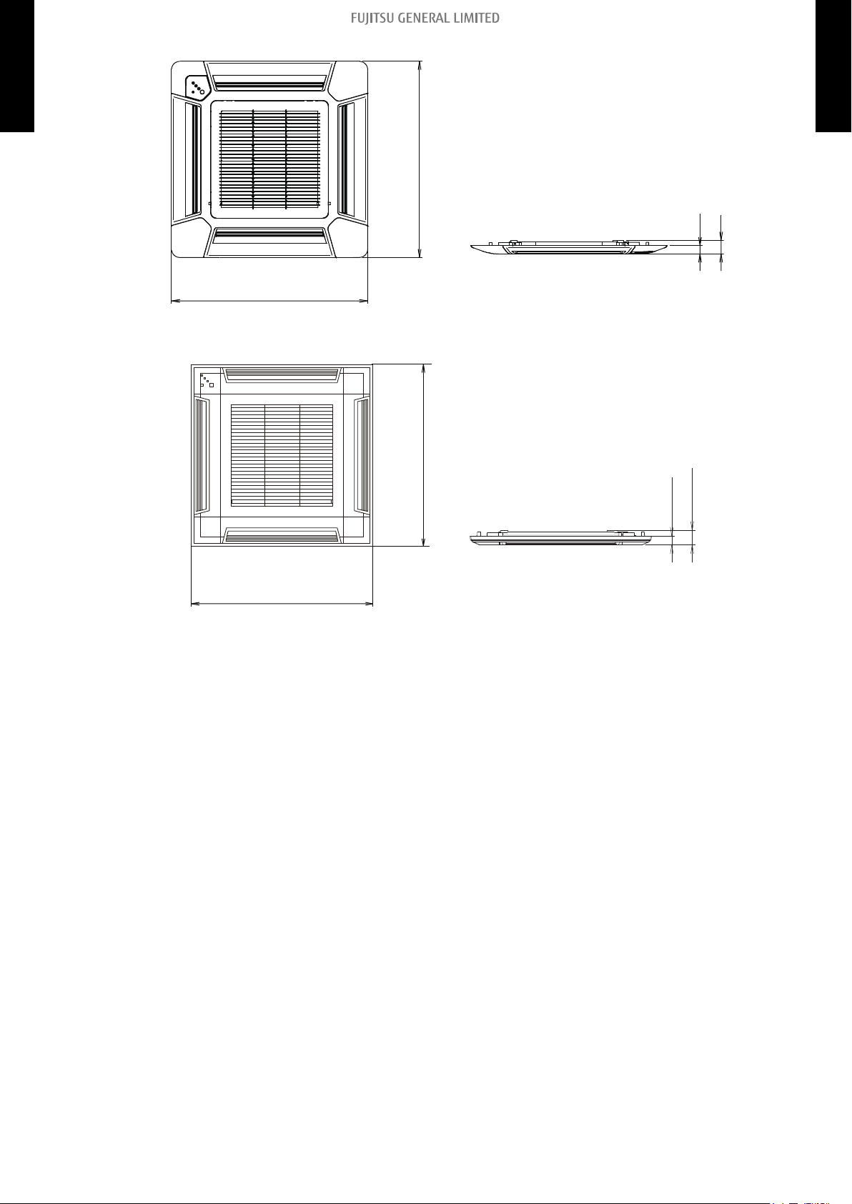
Page 21

3. Dimensions
20-7/8 (530): Hanging bolt position
4 (102)
5-5/16
(135)
9-13/16 (250)
2-15/16 (75)
1-3/16 (30)
1-3/16 (30)
10-5/16 (262)
21-1/4 (540): Hanging bolt position
22-7/16 (570): Indoor unit
a (Ceiling openings)
•
Cassette grille mounting state
Top view
5-14/16 to 7-7/8 (150 to 200)
Min. 17-11/16 (450)
Min. 17-11/16 (450)
Maintenance space
Side view
8-7/16 (215)
4-13/16 (123)
2-5/16 (58)
4-1/2 (114)
5-3/4 (146)
4-1/4
(108)
4 (102)
9-5/8 (245)
1-3/16 (30)
1-9/16 (40)
3-7/8 (99)
Drain port
Control box
Ceiling
Drain port
Be sure to leave
maintenance space
for future service
at the designated
position.
Unit: in (mm)
MULTI TYPE
3-1. Compact cassette type
2, 3, 4 ROOMS TYPE
¢
Models: AUU7RLF, AUU9RLF, AUU12RLF, and AUU18RLF
MULTI TYPE
2, 3, 4 ROOMS TYPE
a (Ceiling openings size):
Standard type grille
UTG-CCGF
22-13/16 to 26
(580 to 660)
Grid type grille
UTG-CCGFG
22-13/16 to 24
(580 to 610)
3-1. Compact cassette type 3. Dimensions
- 13 -
Page 22
• Standard type grille (UTG-CCGF)
27-9/16 (700)
27-9/16 (700)
Bottom view
1-3/16 (30)
1-15/16 (49)
Side view
24-7/16 (620)
24-7/16 (620)
Bottom view
Side view
1-3/16 (30)
1-15/16 (49)
MULTI TYPE
2, 3, 4 ROOMS TYPE
• Grid type grille (UTG-CCGFG)
MULTI TYPE
2, 3, 4 ROOMS TYPE
3-1. Compact cassette type 3. Dimensions
- 14 -
Page 23

40 (1,000)
or more
40 (1,000)
or more
95 (2,400)
or more
11 (262)
or more
Strong and durable ceiling
Obstruction
Floor
Unit: in (mm)
4 (100) or more*
Unit: in (mm)
MULTI TYPE
2, 3, 4 ROOMS TYPE
Model name AUU7RLF and AUU9RLF AUU12RLF and AUU18RLF
Standard mode
High ceiling mode —
Installation space
Maximum height from floor to ceiling [Unit: in (mm)]
107
(2,700)
119
(3,000)
MULTI TYPE
2, 3, 4 ROOMS TYPE
• 3-way direction setting
NOTES:
3-1. Compact cassette type 3. Dimensions
• *: When installing the indoor unit, be careful about the maintenance space.
• To set “3-direction”, optional Air outlet shutter plate (UTR-YDZB) must be installed, and the “outlet-direction” need to be switched to “3-way” by remote controller.
• The ceiling height cannot be set in the 3-way outlet mode. Therefore, ceiling height setting
change by function setting 20 is prohibited. For details, refer to "Contents of function setting" on
page 149.
- 15 -
Page 24

3-2. Slim duct type
Rear view
View A
Top view
Side view
Front view
Bottom view
Drain port
2 (51)
22-5/8 (574)
6-17/8 (174)
2-13/16 (71)
6 (152)
3-15/16 (100) x 6 = 23-5/8 (600)
3-7/32 (82)
1-7/8 (48)
25-9/16 (650)
28-7/8 (734)
1-3/16 (30)
14-13/16 (377)
6-9/16
(167)
4-11/16 (119)
3-1/2 (89)
3-1/16 (78)
2-3/16 (55)
1-7/8 (47)
3/8 (10)
24-7/16 (620)
14-5/8 (371)
10-3/8 (264)
5-11/16 (144)
2-11/16 (69)
25-9/16 (650)
26-1/8 (664)
27-9/16 (700)
1-11/16 (43)
13/16 (20)
7-13/16 (198)
6-5/8 (168)
5-15/16
(151)
3-1/16 (78) 2-3/16 (55)
Unit: in (mm)
¢ Models: ARU7RLF, ARU9RLF, and ARU12RLF
MULTI TYPE
2, 3, 4 ROOMS TYPE
MULTI TYPE
2, 3, 4 ROOMS TYPE
3-2. Slim duct type 3. Dimensions
- 16 -
Page 25

¢ Model: ARU18RLF
Rear view
View A
Top view
Side view
Front view
Bottom view
Drain port
2 (51)
30-1/2 (774)
6-7/8 (174)
2-13/16 (71)
6 (152)
3-7/16 (87)
2-3/16 (56)
33-7/16 (850)
36-3/4 (934)
3-15/16 (100) x 8 = 31-1/2 (800)
1-3/16 (30)
14-13/16 (377)
6-9/16
(167)
4-11/16 (119)
3-1/2 (89)
3-1/16 (78)
2-3/16 (55)
1-7/8 (47)
3/8 (10)
24-7/16 (620)
14-5/8 (371)
10-3/8 (264)
5-11/16 (144)
2-11/16 (69)
33-7/16 (850)
34 (864)
35-7/16 (900)
1-11/16 (43)
13/16
(20)
7-13/16 (198)
6-5/8 (168)
5-15/16
(151)
3-1/16
(78)
2-3/16 (55)
Unit: in (mm)
MULTI TYPE
2, 3, 4 ROOMS TYPE
MULTI TYPE
2, 3, 4 ROOMS TYPE
3-2. Slim duct type 3. Dimensions
- 17 -
Page 26

¢ Model: ARU24RLF
Rear view
View A
Top view
Side view
Front view
Bottom view
Drain port
38-3/8 (974)
2 (51)
6-7/8 (174)
2-13/16 (71)
6 (152)
44-5/8 (1,134)
2-3/16 (56)
3-7/16 (87)
3-15/16 (100) x 10 = 39-3/8 (1,000)
41-5/16 (1,050)
1-3/16 (30)
14-13/16 (377)
6-9/16 (167)
4-11/16 (119)
3-1/2 (89)
3-1/16 (78)
2-3/16 (55)
1-7/8 (47)
6/16 (10)
24-7/16 (620)
14-5/8 (371)
10-6/16 (264)
5-11/16 (144)
2-11/16 (69)
43-5/16 (1,100)
1-11/16 (43)
13/16 (20)
7-13/16 (198)
6-5/8 (168)
5-15/16
(151)
3-1/16 (78)
2-3/16 (55)
Unit: in (mm)
MULTI TYPE
2, 3, 4 ROOMS TYPE
MULTI TYPE
2, 3, 4 ROOMS TYPE
3-2. Slim duct type 3. Dimensions
- 18 -
Page 27

¢
Left
side
Strong and durable ceiling
Indoor unit
Right
side
4 (100)
or more
12 (300)
or more
Service access Ceiling
99 (2,500) or more
(When no ceiling)
Floor
10 (240) or more
1 (20) or more
1 (20) or more
12 (300) or more
Unit: in (mm)
1 (10)
or less
1 (10)
or less
Left side
Strong and
durable floor
Right side
(PIPE side)
Grille
Inlet air
Strong and
durable floor
6
(150)
or more
4 (100)
or more
12 (300)
or more
1 (20)
or more
1 (20)
or more
6 (150)
or more
Unit: in (mm)
Left side
Strong and
durable floor
Right side
(PIPE side)
Duct
Grille
Inlet air
Strong and
durable floor
6
(150)
or more
4 (100)
or more
12 (300)
or more
1 (20)
or more
1 (20)
or more
6 (150)
or more
Provide sufficient installation space for product safety.
In ceiling-concealed installations:
MULTI TYPE
2, 3, 4 ROOMS TYPE
In wall-concealed installations:
Installation space requirement
MULTI TYPE
2, 3, 4 ROOMS TYPE
3-2. Slim duct type 3. Dimensions
- 19 -
Page 28

Maintenance space requirement
Service access
Unit
Control
box
or more
Service space
12 (300)
12 (300)
or more
4 (100)
or more
Unit: in (mm)
¢
For future maintenance and service access, provide sufficient maintenance space.
MULTI TYPE
2, 3, 4 ROOMS TYPE
NOTE: Do not place any wiring or illumination in the maintenance space, as they will impede ser-
vice.
MULTI TYPE
2, 3, 4 ROOMS TYPE
3-2. Slim duct type 3. Dimensions
- 20 -
Page 29

3-3. Wall mounted type
33-1/16 (840) 8 (203)
10-9/16 (268)
(33-1/16 (840))
1-3/4 (45)
2-1/16 (52)
14-5/16 (364)
Ø2-9/16 (Ø65)
for pipe inlet
12-5/8 (321)
3-7/16
(88)
Ø2-9/16 (Ø65)
for pipe inlet
12-3/8 (315)
4-9/16
(116)
1-5/8(41)
10-9/16 (268)
13-7/8 (353)
3-1/16 (78)
11/16 (18)7/16 (11)
1-5/8 (41)
Unit: in (mm)
¢
MULTI TYPE
2, 3, 4 ROOMS TYPE
Models: ASU7RLF1, ASU9RLF1, ASU12RLF1, and ASU15RLF1
MULTI TYPE
2, 3, 4 ROOMS TYPE
3-3. Wall mounted type 3. Dimensions
- 21 -
Page 30

71 (1,800) or more
60 (1,500) or more
1 (25)
or more
Outline of unit
3 (70)
or more
3 (52)
or more
2 (45) or more
3 (63) or more
6 (130)
or more
Unit: in (mm)
MULTI TYPE
2, 3, 4 ROOMS TYPE
Installation space
MULTI TYPE
2, 3, 4 ROOMS TYPE
3-3. Wall mounted type 3. Dimensions
- 22 -
Page 31

¢
Unit: in (mm)
8-1/16 (205) : Installed state
*1: Vertical flap is downward
8 (203)
5-1/2 (140) *1
6/16 (10) *1
5-11/16 (145) *1
31-1/8 (790)
11 (280)
3-11/16 (94)
2-1/16 (52)
3-1/16 (78)
ø2-9/16 (65)
for pipe inlet
ø2-9/16 (65)
for pipe inlet
Outline of unit
12-11/16 (323)
13-7/8 (353): Gas pipe
16-5/16 (415): Liquid pipe
12-7/8 (327)
9-5/16 (237)
17-11/16 (450)
8-1/4 (209)
2-7/16 (62)
11/16 (18)
1-7/8 (47)
1-7/8 (47)
7-1/4 (184)
8-7/16 (215)
11/16 (18)
3-1/4 (82)
MULTI TYPE
2, 3, 4 ROOMS TYPE
Models: ASU7RLF, ASU9RLF, and ASU12RLF
MULTI TYPE
2, 3, 4 ROOMS TYPE
3-3. Wall mounted type 3. Dimensions
- 23 -
Page 32

Unit: in (mm)
60 (1,500) or more
71 (1,800) or more
3 (63) or more
2 (45) or more
2 (48) or more
3 (52) or more
Outline of unit
3 (70) or more
4 (100) or more
MULTI TYPE
2, 3, 4 ROOMS TYPE
Installation space
MULTI TYPE
2, 3, 4 ROOMS TYPE
- 24 -
3-3. Wall mounted type 3. Dimensions
Page 33

¢ Models: ASU9RLS2, ASU12RLS2, and ASU15RLS2
Unit: in (mm)
7-7/8 (35)7-7/8 (200)
1-15/16 (49)
(3-5/16 (84)) 13-7/8 (353)
8-7/16 (214) 7 (178)
14-5/16 (364) 2-3/4 (70)
1-15/16 (49)
(11-2/16 (282))
13/16 (20)
12-1/4 (311)12-3/8 (315)
Outline of Unit
Ø2-9/16 (65)
for pipe inlet
(34-1/4 (870))
Ø2-9/16 (65)
for pipe inlet
11-1/8 (282)
7-5/16 (185)34-1/4 (870)
7-3/8(187) : Installed state
MULTI TYPE
2, 3, 4 ROOMS TYPE
MULTI TYPE
2, 3, 4 ROOMS TYPE
3-3. Wall mounted type 3. Dimensions
- 25 -
Page 34

Unit: in (mm)
2 (50) or more
60 (1,500) or more
10 (247)
3
(55)
71 (1,800) or more
14 (337)
7 (162) or more
2 (50) or more
7 (162) or more
4 (100) or more
5 (120) or more
Outline of Unit
MULTI TYPE
2, 3, 4 ROOMS TYPE
Installation space
MULTI TYPE
2, 3, 4 ROOMS TYPE
3-3. Wall mounted type 3. Dimensions
- 26 -
Page 35

¢
39-5/16 (998)
17-1/4 (438)
15-5/8 (397)
12-5/8 (320): Unit size
2 (51)
2 (51)
13/16 (20)
2-5/8 (67)1-1/8 (28)
35-9/16 (903)
Ø 3-1/8 (80) hole
39-5/16 (998): Unit size
Outline of unit
Piping inlet
Unit center
9 (228)
12-5/8 (320)
Ø 3-1/8 (80) hole
Piping inlet
11/16 (17)
7/16 (11)
Unit: in (mm)
MULTI TYPE
2, 3, 4 ROOMS TYPE
Models: ASU18RLF and ASU24RLF
MULTI TYPE
2, 3, 4 ROOMS TYPE
3-3. Wall mounted type 3. Dimensions
- 27 -
Page 36

3 (63) or more
4 (80) or more
3 (53) or more
3 (52) or more
4 (80) or more
Outline of unit
5 (120) or more
60 (1,500) or more
71 (1,800) or more
Unit: in (mm)
MULTI TYPE
2, 3, 4 ROOMS TYPE
Installation space
MULTI TYPE
2, 3, 4 ROOMS TYPE
3-3. Wall mounted type 3. Dimensions
- 28 -
Page 37

3-4. Floor type
23-5/8 (600)
7-7/8 (200)
Side view
Front view
29-1/8 (740)
Unit: in (mm)
4 (80)
or more
2 (50)
or more
4 (80) or more
4 (100) or more
5 (150) or less
Unit: in (mm)
¢ Models: AGU9RLF, AGU12RLF, and AGU15RLF
MULTI TYPE
2, 3, 4 ROOMS TYPE
MULTI TYPE
2, 3, 4 ROOMS TYPE
¢
Installation space
3-4. Floor type 3. Dimensions
- 29 -
Page 38

4. Wiring diagrams
MULTI TYPE
4-1. Compact cassette type
2, 3, 4 ROOMS TYPE
¢
Models: AUU7RLF, AUU9RLF, AUU12RLF, and AUU18RLF
MULTI TYPE
2, 3, 4 ROOMS TYPE
4-1. Compact cassette type 4. Wiring diagrams
- 30 -
Page 39

4-2. Slim duct type
¢
MULTI TYPE
2, 3, 4 ROOMS TYPE
Models: ARU7RLF, ARU9RLF, ARU12RLF, ARU18RLF, and ARU24RLF
MULTI TYPE
2, 3, 4 ROOMS TYPE
4-2. Slim duct type 4. Wiring diagrams
- 31 -
Page 40

4-3. Wall mounted type
¢
MULTI TYPE
2, 3, 4 ROOMS TYPE
Models: ASU7RLF1, ASU9RLF1, ASU12RLF1, and ASU15RLF1
MULTI TYPE
2, 3, 4 ROOMS TYPE
4-3. Wall mounted type 4. Wiring diagrams
- 32 -
Page 41

¢
MULTI TYPE
2, 3, 4 ROOMS TYPE
Models: ASU7RLF, ASU9RLF, and ASU12RLF
MULTI TYPE
2, 3, 4 ROOMS TYPE
4-3. Wall mounted type 4. Wiring diagrams
- 33 -
Page 42

¢
MULTI TYPE
2, 3, 4 ROOMS TYPE
Models: ASU9RLS2, ASU12RLS2, and ASU15RLS2
MULTI TYPE
2, 3, 4 ROOMS TYPE
4-3. Wall mounted type 4. Wiring diagrams
- 34 -
Page 43

¢
MULTI TYPE
2, 3, 4 ROOMS TYPE
Models: ASU18RLF and ASU24RLF
MULTI TYPE
2, 3, 4 ROOMS TYPE
4-3. Wall mounted type 4. Wiring diagrams
- 35 -
Page 44

4-4. Floor type
¢
MULTI TYPE
2, 3, 4 ROOMS TYPE
Models: AGU9RLF, AGU12RLF, and AGU15RLF
MULTI TYPE
2, 3, 4 ROOMS TYPE
4-4. Floor type 4. Wiring diagrams
- 36 -
Page 45

5. Air velocity and temperature distributions
7 (2.0)
7 (2.0)
7 (2.0)
7 (2.0)
3 (1.0)
3 (1.0)
3 (1.0)
3 (1.0)
2 (0.5)
2 (0.5)
2 (0.5)
2 (0.5)
1 (0.25)
1 (0.25)
1 (0.25)
1 (0.25)
Unit: ft/s (m/s)
(m)(ft)
00
3
3
7
7
10
10
13
13
1
1
2
2
3
3
4
4
(m)
(ft)
0
0
11
33771010 1313
2233 44
7 (2.0)
3 (1.0)
2 (0.5) 2 (0.5)
1 (0.25) 1 (0.25)
Unit: ft/s (m /s)
(m)(ft)
0
0
3
7
9
1
2
2.7
(m)
(ft)
0
0
11
33771010 1313
2233 44
MULTI TYPE
5-1. Compact cassette type
2, 3, 4 ROOMS TYPE
¢
• Air velocity distribution
Measuring conditions
Top view
Vertical airflow direction louver: Up
Models: AUU7RLF and AUU9RLF
Fan speed Operation mode
HIGH FAN
MULTI TYPE
2, 3, 4 ROOMS TYPE
Side view
Vertical airflow direction louver: Up
5-1. Compact cassette type 5. Air velocity and temperature distributions
- 37 -
Page 46

Measuring conditions
7 (2.0) 7 (2.0)
5 (1.5) 5 (1.5)
3 (1.0) 3 (1.0)
2 (0.5) 2 (0.5)
1 (0.25) 1 (0.25)
Unit: ft/s (m/s)
(m)(ft)
0
0
3
7
9
8
1
2
2.7
2.5
(m)
(ft)
0
0
11
33771010 1313
2233 44
86
(3 0) 8 6 ( 3 0)
82
(28)
82
(28)
79
(26)
79 (26)
75 (24)
75
(24)
72 (22) 72 (22)
Unit: °F (°C)
(m)(ft)
0
0
3
7
9
8
1
2
2.7
2.5
(m)
(ft)
0
0
11
33771010 1313
2233 44
NOTE: Reference data
• Air velocity distribution
MULTI TYPE
2, 3, 4 ROOMS TYPE
Side view
Vertical airflow direction louver: Down
• Air temperature distribution
Side view
Vertical airflow direction louver: Down
Fan speed Operation mode Outlet directions
HIGH HEAT 4-way air outlet
MULTI TYPE
2, 3, 4 ROOMS TYPE
5-1. Compact cassette type 5. Air velocity and temperature distributions
- 38 -
Page 47

¢
7 (2.0)
7 (2.0)
7 (2.0)
7 (2.0)
3 (1.0)
3 (1.0)
3 (1.0)
3 (1.0)
2 (0.5)
2 (0.5)
2 (0.5)
2 (0.5)
1 (0.25)
1 (0.25)
1 (0.25)
1 (0.25)
Unit: ft/s (m/s)
4
3
2
1
0
1
2
3
4
43
210
1
2
34
(m)
(m)
0
3
7
(ft)
3
7
10
13
10
13
13
10
7
3
0
3
7
10
13
(ft)
7 (2.0)
3 (1.0)
2 (0.5)
2 (0.5)
1 (0.25)
1 (0.25)
43
2
1
0
1
2
34
(m)
0
1
2
2.7
(m)
Unit: ft/s (m/s)
0
3
7
9
(ft)
13
10
7
3
0
3
7
10
13
(ft)
• Air velocity distribution
MULTI TYPE
2, 3, 4 ROOMS TYPE
Measuring conditions
Top view
Vertical airflow direction louver: Up
Model: AUU12RLF
Fan speed Operation mode
HIGH FAN
MULTI TYPE
2, 3, 4 ROOMS TYPE
Side view
Vertical airflow direction louver: Up
5-1. Compact cassette type 5. Air velocity and temperature distributions
- 39 -
Page 48

Measuring conditions
5 (1.5) 5 (1.5)
3 (1.0) 3 (1.0)
2 (0.5) 2 (0.5)
1 (0.25) 1 (0.25)
43
2
1
0
1
2
34
(m)
0
1
2
2.7
(m)
Unit: ft/s (m/s)
0
3
7
9
(ft)
13
10
7
3
0
3
7
10
13
(ft)
2.5
8
86 (30) 86 (30)
82 (28) 82 (28)
79 (26) 79 (26)
75 (24) 75 (24)
72 (22) 72 (22)
43
2
1
0
1
2
34
(m)
0
1
2
2.7
(m)
Unit: ft/s (m/s)
0
3
7
9
(ft)
13
10
7
3
0
3
7
10
13
(ft)
2.5
8
NOTE: Reference data
• Air velocity distribution
MULTI TYPE
2, 3, 4 ROOMS TYPE
Side view
Vertical airflow direction louver: Down
• Air temperature distribution
Fan speed Operation mode Outlet directions
HIGH HEAT 4-way air outlet
MULTI TYPE
2, 3, 4 ROOMS TYPE
Side view
Vertical airflow direction louver: Down
5-1. Compact cassette type 5. Air velocity and temperature distributions
- 40 -
Page 49

¢
7 (2.0)
7 (2.0)
7 (2.0)
7 (2.0)
3 (1.0)
3 (1.0)
3 (1.0)
3 (1.0)
2 (0.5)
2 (0.5)
2 (0.5)
2 (0.5)
1 (0.25)
1 (0.25)
1 (0.25)
1 (0.25)
Unit: ft/s (m/s)
4
3
2
1
0
1
2
3
4
43
210
1
2
34
(m)
(m)
0
3
7
(ft)
3
7
10
13
10
13
13
10
7
3
0
3
7
10
13
(ft)
7 (2.0)
3 (1.0)
2 (0.5)
2 (0.5)
1 (0.25)
1 (0.25)
43
2
1
0
1
2
34
(m)
0
1
2
2.7
(m)
Unit: ft/s (m/s)
0
3
7
9
(ft)
13
10
7
3
0
3
7
10
13
(ft)
• Air velocity distribution
MULTI TYPE
2, 3, 4 ROOMS TYPE
Measuring conditions
Top view
Vertical airflow direction louver: Up
Model: AUU18RLF
Fan speed Operation mode
HIGH FAN
MULTI TYPE
2, 3, 4 ROOMS TYPE
Side view
Vertical airflow direction louver: Up
5-1. Compact cassette type 5. Air velocity and temperature distributions
- 41 -
Page 50

Measuring conditions
5 (1.5) 5 (1.5)
3 (1.0) 3 (1.0)
2 (0.5) 2 (0.5)
1 (0.25) 1 (0.25)
7 (2.0) 7 (2.0)
43
2
1
0
1
2
34
(m)
0
1
2
2.7
(m)
Unit: ft/s (m/s)
0
3
7
9
(ft)
13
10
7
3
0
3
7
10
13
(ft)
2.5
8
86 (30) 86 (30)
82 (28) 82 (28)
79 (26) 79 (26)
75 (24) 75 (24)
72 (22) 72 (22)
43
2
1
0
1
2
34
(m)
0
1
2
2.7
(m)
Unit: ft/s (m/s)
0
3
7
9
(ft)
13
10
7
3
0
3
7
10
13
(ft)
2.5
8
NOTE: Reference data
• Air velocity distribution
MULTI TYPE
2, 3, 4 ROOMS TYPE
Side view
Vertical airflow direction louver: Down
• Air temperature distribution
Fan speed Operation mode Outlet directions
HIGH HEAT 4-way air outlet
MULTI TYPE
2, 3, 4 ROOMS TYPE
Side view
Vertical airflow direction louver: Down
5-1. Compact cassette type 5. Air velocity and temperature distributions
- 42 -
Page 51

5-2. Slim duct type
2
1
0
1
2
(m)
Unit: ft/s (m/s)
7
3
0
3
7
(ft)
7 (2)
3 (1)
2 (0.5)
(m)
0
12 3
456
7
(ft)
7
20
89
10
0
3
10
13 16
23 26 29
32
2
1
0
1
2
(m)
(m)
Unit: ft/s (m/s)
0
12 3
456
7
(ft)
7
20
7
3
0
3
7
(ft)
7 (2)
3 (1)
2 (0.5)
5
4
3
16
13
10
89
10
0
3
10
13 16
23 26 29
32
5
4
3
16
13
10
3 (1)
2 (0.5)
7 (2)
2
1
0
(m)
Unit: ft/s (m/s)
7
3
0
(ft)
7 (2)
3 (1)
2 (0.5)
(m)
0
12 3
456
7
(ft)
7
20
89
10
0
3
10
13 16
23 26 29
32
2.58
310
¢
MULTI TYPE
2, 3, 4 ROOMS TYPE
Measuring conditions
• Air velocity distribution
Top view
Vertical airflow direction louver: Up
Horizontal airflow direction louver: Center
Model: ARU7RLF
NOTE: This data is measured after installing optional Auto louver grille kit.
Fan speed Operation mode
HIGH FAN
MULTI TYPE
2, 3, 4 ROOMS TYPE
Top view
Vertical airflow direction louver: Up
Horizontal airflow direction louver: Left & Right
Side view
Vertical airflow direction louver: Up
Horizontal airflow direction louver: Center
5-2. Slim duct type 5. Air velocity and temperature distributions
- 43 -
Page 52

Measuring conditions
2
1
0
(m)
Unit: ft/s (m/s)
7
3
0
(ft)
7 (2)
3 (1)
2 (0.5)
(m)
0
12 3
456
7
(ft)
7
20
89
10
0
3
10
13 16
23 26 29
32
2.58
310
2
1
0
(m)
Unit: °F (°C)
7
3
0
(ft)
86 (30)
(m)
0
12 3
456
7
(ft)
7
20
89
10
0
3
10
13 16
23 26 29
32
2.58
310
82 (28)
79 (26)
75 (24)
72 (22)
• Air velocity distribution
MULTI TYPE
2, 3, 4 ROOMS TYPE
Side view
Vertical airflow direction louver: Down
Horizontal airflow direction louver: Center
• Air temperature distribution
Side view
Vertical airflow direction louver: Down
Horizontal airflow direction louver: Center
Fan speed Operation mode
HIGH HEAT
MULTI TYPE
2, 3, 4 ROOMS TYPE
5-2. Slim duct type 5. Air velocity and temperature distributions
- 44 -
Page 53

¢
2
1
0
1
2
(m)
Unit: ft/s (m/s)
7
3
0
3
7
(ft)
7 (2)
3 (1)
2 (0.5)
(m)
0
12 3
456
7
(ft)
7
20
89
10
0
3
10
13 16
23 26 29
32
2
1
0
1
2
(m)
(m)
Unit: ft/s (m/s)
0
12 3
456
7
(ft)
7
20
7
3
0
3
7
(ft)
7 (2)
3 (1)
2 (0.5)
5
4
3
16
13
10
89
10
0
3
10
13 16
23 26 29
32
5
4
3
16
13
10
3 (1)
2 (0.5)
7 (2)
2
1
0
(m)
Unit: ft/s (m/s)
7
3
0
(ft)
7 (2)
3 (1)
2 (0.5)
(m)
0
12 3
456
7
(ft)
7
20
89
10
0
3
10
13 16
23 26 29
32
2.5
8
310
MULTI TYPE
2, 3, 4 ROOMS TYPE
Measuring conditions
• Air velocity distribution
Top view
Vertical airflow direction louver: Up
Horizontal airflow direction louver: Center
Model: ARU9RLF
NOTE: This data is measured after installing optional Auto louver grille kit.
Fan speed Operation mode
HIGH FAN
MULTI TYPE
2, 3, 4 ROOMS TYPE
Top view
Vertical airflow direction louver: Up
Horizontal airflow direction louver: Left & Right
Side view
Vertical airflow direction louver: Up
Horizontal airflow direction louver: Center
- 45 -
5-2. Slim duct type 5. Air velocity and temperature distributions
Page 54

Measuring conditions
2
1
0
(m)
Unit: ft/s (m/s)
7
3
0
(ft)
7 (2)
3 (1)
2 (0.5)
(m)
0
12 3
456
7
(ft)
7
20
89
10
0
3
10
13 16
23 26 29
32
2.5
8
3
10
2
1
0
(m)
Unit: °F (°C)
7
3
0
(ft)
86 (30)
(m)
0
12 3
456
7
(ft)
7
20
89
10
0
3
10
13 16
23 26 29
32
2.58
310
82 (28)
79 (26)
75 (24)
72 (22)
• Air velocity distribution
MULTI TYPE
2, 3, 4 ROOMS TYPE
Side view
Vertical airflow direction louver: Down
Horizontal airflow direction louver: Center
• Air temperature distribution
Side view
Vertical airflow direction louver: Down
Horizontal airflow direction louver: Center
Fan speed Operation mode
HIGH HEAT
MULTI TYPE
2, 3, 4 ROOMS TYPE
5-2. Slim duct type 5. Air velocity and temperature distributions
- 46 -
Page 55

¢
2
1
0
1
2
(m)
Unit: ft/s (m/s)
7
3
0
3
7
(ft)
7 (2)
3 (1)
2 (0.5)
(m)
0
12 3
456
7
(ft)
7
20
89
10
0
3
10
13 16
23 26 29
32
2
1
0
1
2
(m)
(m)
Unit: ft/s (m/s)
0
12 3
456
7
(ft)
7
20
7
3
0
3
7
(ft)
7 (2)
3 (1)
2 (0.5)
5
4
3
16
13
10
89
10
0
3
10
13 16
23 26 29
32
5
4
3
16
13
10
3 (1)
2 (0.5)
7 (2)
2
1
0
(m)
Unit: ft/s (m/s)
7
3
0
(ft)
7 (2)
3 (1)
2 (0.5)
(m)
0
12 3
456
7
(ft)
7
20
89
10
0
3
10
13 16
23 26 29
32
2.58
3
10
MULTI TYPE
2, 3, 4 ROOMS TYPE
Measuring conditions
• Air velocity distribution
Top view
Vertical airflow direction louver: Up
Horizontal airflow direction louver: Center
Model: ARU12RLF
NOTE: This data is measured after installing optional Auto louver grille kit.
Fan speed Operation mode
HIGH FAN
MULTI TYPE
2, 3, 4 ROOMS TYPE
Top view
Vertical airflow direction louver: Up
Horizontal airflow direction louver: Left & Right
Side view
Vertical airflow direction louver: Up
Horizontal airflow direction louver: Center
5-2. Slim duct type 5. Air velocity and temperature distributions
- 47 -
Page 56

Measuring conditions
2
1
0
(m)
Unit: ft/s (m/s)
7
3
0
(ft)
7 (2)
3 (1)
2 (0.5)
(m)
0
12 3
456
7
(ft)
7
20
89
10
0
3
10
13 16
23 26 29
32
2.5
8
310
2
1
0
(m)
Unit: °F (°C)
7
3
0
(ft)
86 (30)
(m)
0
12 3
456
7
(ft)
7
20
89
10
0
3
10
13 16
23 26 29
32
2.58
310
82 (28)
79 (26)
75 (24)
72 (22)
• Air velocity distribution
MULTI TYPE
2, 3, 4 ROOMS TYPE
Side view
Vertical airflow direction louver: Down
Horizontal airflow direction louver: Center
• Air temperature distribution
Side view
Vertical airflow direction louver: Down
Horizontal airflow direction louver: Center
Fan speed Operation mode
HIGH HEAT
MULTI TYPE
2, 3, 4 ROOMS TYPE
5-2. Slim duct type 5. Air velocity and temperature distributions
- 48 -
Page 57

¢
2
1
0
1
2
(m)
Unit: ft/s (m/s)
7
3
0
3
7
(ft)
7 (2)
3 (1)
2 (0.5)
(m)
0
12 3
456
7
(ft)
7
20
89
10
0
3
10
13 16
23 26 29
32
2
1
0
1
2
(m)
(m)
Unit: ft/s (m/s)
0
12 3
456
7
(ft)
7
20
7
3
0
3
7
(ft)
7 (2)
3 (1)
2 (0.5)
5
4
3
16
13
10
89
10
0
3
10
13 16
23 26 29
32
5
4
3
16
13
10
3 (1)
2 (0.5)
7 (2)
2
1
0
(m)
Unit: ft/s (m/s)
7
3
0
(ft)
7 (2)
3 (1)
2 (0.5)
(m)
0
12 3
456
7
(ft)
7
20
89
10
0
3
10
13 16
23 26 29
32
2.5
8
3
10
MULTI TYPE
2, 3, 4 ROOMS TYPE
Measuring conditions
• Air velocity distribution
Top view
Vertical airflow direction louver: Up
Horizontal airflow direction louver: Center
Model: ARU18RLF
NOTE: This data is measured after installing optional Auto louver grille kit.
Fan speed Operation mode
HIGH FAN
MULTI TYPE
2, 3, 4 ROOMS TYPE
Top view
Vertical airflow direction louver: Up
Horizontal airflow direction louver: Left & Right
Side view
Vertical airflow direction louver: Up
Horizontal airflow direction louver: Center
- 49 -
5-2. Slim duct type 5. Air velocity and temperature distributions
Page 58

Measuring conditions
2
1
0
(m)
Unit: ft/s (m/s)
7
3
0
(ft)
7 (2)
3 (1)
2 (0.5)
(m)
0
12 3
456
7
(ft)
7
20
89
10
0
3
10
13 16
23 26 29
32
2.58
3
10
2
1
0
(m)
Unit: °F (°C)
7
3
0
(ft)
86 (30)
(m)
0
12 3
456
7
(ft)
7
20
89
10
0
3
10
13 16
23 26 29
32
2.58
310
82 (28)
79 (26)
75 (24)
72 (22)
• Air velocity distribution
MULTI TYPE
2, 3, 4 ROOMS TYPE
Side view
Vertical airflow direction louver: Down
Horizontal airflow direction louver: Center
• Air temperature distribution
Side view
Vertical airflow direction louver: Down
Horizontal airflow direction louver: Center
Fan speed Operation mode
HIGH HEAT
MULTI TYPE
2, 3, 4 ROOMS TYPE
5-2. Slim duct type 5. Air velocity and temperature distributions
- 50 -
Page 59

¢
2
1
0
1
2
(m)
Unit: ft/s (m/s)
7
3
0
3
7
(ft)
7 (2)
3 (1)
2 (0.5)
(m)
0
12 3
456
7
(ft)
7
20
89
10
0
3
10
13 16
23 26 29
32
2
1
0
1
2
(m)
(m)
Unit: ft/s (m/s)
0
12 3
456
7
(ft)
7
20
7
3
0
3
7
(ft)
7 (2)
3 (1)
2 (0.5)
5
4
3
16
13
10
89
10
0
3
10
13 16
23 26 29
32
5
4
3
16
13
10
3 (1)
2 (0.5)
7 (2)
2
1
0
(m)
Unit: ft/s (m/s)
7
3
0
(ft)
7 (2)
3 (1)
2 (0.5)
(m)
0
12 3
456
7
(ft)
7
20
89
10
0
3
10
13 16
23 26 29
32
2.5
8
3
10
MULTI TYPE
2, 3, 4 ROOMS TYPE
Measuring conditions
• Air velocity distribution
Top view
Vertical airflow direction louver: Up
Horizontal airflow direction louver: Center
Model: ARU24RLF
NOTE: This data is measured after installing optional Auto louver grille kit.
Fan speed Operation mode
HIGH FAN
MULTI TYPE
2, 3, 4 ROOMS TYPE
Top view
Vertical airflow direction louver: Up
Horizontal airflow direction louver: Left & Right
Side view
Vertical airflow direction louver: Up
Horizontal airflow direction louver: Center
5-2. Slim duct type 5. Air velocity and temperature distributions
- 51 -
Page 60

Measuring conditions
2
1
0
(m)
Unit: ft/s (m/s)
7
3
0
(ft)
7 (2)
3 (1)
2 (0.5)
(m)
0
12 3
456
7
(ft)
7
20
89
10
0
3
10
13 16
23 26 29
32
2.58
310
2
1
0
(m)
Unit: °F (°C)
7
3
0
(ft)
86 (30)
(m)
0
12 3
456
7
(ft)
7
20
89
10
0
3
10
13 16
23 26 29
32
2.5
8
3
10
82 (28)
79 (26)
75 (24)
72 (22)
• Air velocity distribution
MULTI TYPE
2, 3, 4 ROOMS TYPE
Side view
Vertical airflow direction louver: Down
Horizontal airflow direction louver: Center
• Air temperature distribution
Side view
Vertical airflow direction louver: Down
Horizontal airflow direction louver: Center
Fan speed Operation mode
HIGH HEAT
MULTI TYPE
2, 3, 4 ROOMS TYPE
5-2. Slim duct type 5. Air velocity and temperature distributions
- 52 -
Page 61

5-3. Wall mounted type
7 (2.0)
3 (1.0) 2 (0.5)
2
1
0
1
2
Unit: ft/s (m/s)
(m)
(m)
01234567
8
7
3
0
3
7
(ft)
(ft)
0 3 7 10 13 16 20 23
26
9
29
7 (2.0)
7 (2.0)
2 (0.5)
2 (0.5)
3 (1.0)
3 (1.0)
10
7
3
0
3
7
10
(ft)
(ft)
0 3 7 10 13 16 20 23
26
3
2
1
0
1
2
3
Unit: ft/s (m/s)
(m)
(m)
01234567
8
9
29
7 (2.0)
2 (0.5)
3 (1.0)
3
2
1
0
Unit: ft/s (m/s)
(m)
(m)
012345678
10
7
3
0
(ft)
(ft)
0 3 7 10 13 16 20 23 26
9
29
2 (0.5)
7 (2.0)
3 (1.0)
3
2
1
0
Unit: ft/s (m/s)
(m)
(m)
012345678
10
7
3
0
(ft)
(ft)
0 3 7 10 13 16 20 23 26
9
29
¢
MULTI TYPE
2, 3, 4 ROOMS TYPE
Measuring conditions
Top view
Vertical airflow direction louver: Up
Horizontal airflow direction louver: Center
Top view
Vertical airflow direction louver: Up
Horizontal airflow direction louver: Left & Right
Model: ASU7RLF1
Fan speed Operation mode
HIGH FAN
MULTI TYPE
2, 3, 4 ROOMS TYPE
Side view
Vertical airflow direction louver: Up
Horizontal airflow direction louver: Center
Side view
Vertical airflow direction louver: Down
Horizontal airflow direction louver: Center
5-3. Wall mounted type 5. Air velocity and temperature distributions
- 53 -
Page 62

Model: ASU9RLF1
7 (2.0)
3 (1.0) 2 (0.5)
2
1
0
1
2
Unit: ft/s (m/s)
(m)
(m)
01234567
8
7
3
0
3
7
(ft)
(ft)
0 3 7 10 13 16 20 23
26
9
29
7 (2.0)
7 (2.0)
2 (0.5)
2 (0.5)
3 (1.0)
3 (1.0)
10
7
3
0
3
7
10
(ft)
(ft)
0 3 7 10 13 16 20 23
26
3
2
1
0
1
2
3
Unit: ft/s (m/s)
(m)
(m)
01234567
8
9
29
3 (1.0) 2 (0.5)
7 (2.0)
3
2
1
0
Unit: ft/s (m/s)
(m)
(m)
012345678
10
7
3
0
(ft)
(ft)
0 3 7 10 13 16 20 23 26
9
29
3 (1.0)
2 (0.5)
7 (2.0)
3
2
1
0
Unit: ft/s (m/s)
(m)
(m)
012345678
10
7
3
0
(ft)
(ft)
0 3 7 10 13 16 20 23 26
9
29
¢
Measuring conditions
MULTI TYPE
2, 3, 4 ROOMS TYPE
Top view
Vertical airflow direction louver: Up
Horizontal airflow direction louver: Center
Top view
Vertical airflow direction louver: Up
Horizontal airflow direction louver: Left & Right
Fan speed Operation mode
HIGH FAN
MULTI TYPE
2, 3, 4 ROOMS TYPE
Side view
Vertical airflow direction louver: Up
Horizontal airflow direction louver: Center
Side view
Vertical airflow direction louver: Down
Horizontal airflow direction louver: Center
5-3. Wall mounted type 5. Air velocity and temperature distributions
- 54 -
Page 63

Model: ASU12RLF1
3 (1.0) 2 (0.5)
7 (2.0)
2
1
0
1
2
Unit: ft/s (m/s)
(m)
(m)
01234567
8
7
3
0
3
7
(ft)
(ft)
0 3 7 10 13 16 20 23
26
9
29
7 (2.0)
7 (2.0)
2 (0.5)
2 (0.5)
3 (1.0)
3 (1.0)
10
7
3
0
3
7
10
(ft)
(ft)
0 3 7 10 13 16 20 23
26
3
2
1
0
1
2
3
Unit: ft/s (m/s)
(m)
(m)
01234567
8
9
29
3 (1.0)
2 (0.5)
7 (2.0)
3
2
1
0
Unit: ft/s (m/s)
(m)
(m)
012345678
10
7
3
0
(ft)
(ft)
0 3 7 10 13 16 20 23 26
9
29
7 (2.0)
3 (1.0)
2 (0.5)
3
2
1
0
Unit: ft/s (m/s)
(m)
(m)
012345678
10
7
3
0
(ft)
(ft)
0 3 7 10 13 16 20 23 26
9
29
¢
Measuring conditions
MULTI TYPE
2, 3, 4 ROOMS TYPE
Top view
Vertical airflow direction louver: Up
Horizontal airflow direction louver: Center
Top view
Vertical airflow direction louver: Up
Horizontal airflow direction louver: Left & Right
Fan speed Operation mode
HIGH FAN
MULTI TYPE
2, 3, 4 ROOMS TYPE
Side view
Vertical airflow direction louver: Up
Horizontal airflow direction louver: Center
Side view
Vertical airflow direction louver: Down
Horizontal airflow direction louver: Center
5-3. Wall mounted type 5. Air velocity and temperature distributions
- 55 -
Page 64

Model: ASU15RLF1
7 (2.0)
3 (1.0)
2 (0.5)
2
1
0
1
2
Unit: ft/s (m/s)
(m)
(m)
0123456
78
7
3
0
3
7
(ft)
(ft)
03710131620
23
26
9
29
3 (1.0)
3 (1.0)
2 (0.5)
2 (0.5)
7 (2.0)
7 (2.0)
10
7
3
0
3
7
10
(ft)
(ft)
03
710 13162023
26
3
2
1
0
1
2
3
Unit: ft/s (m/s)(m)
(m)
01
234567
8
9
29
7 (2.0)
3 (1.0)
2 (0.5)
3
2
1
0
Unit: ft/s (m/s)
(m)
(m)
012345678
10
7
3
0
(ft)
(ft)
037101316202326
9
29
7 (2.0)
3 (1.0)
2 (0.5)
3
2
1
0
Unit: ft/s (m/s)
(m)
(m)
012 34 5 67 8
10
7
3
0
(ft)
(ft)
0 3 7 10 13 16 20 23 26
9
29
¢
Measuring conditions
MULTI TYPE
2, 3, 4 ROOMS TYPE
Top view
Vertical airflow direction louver: Up
Horizontal airflow direction louver: Center
Top view
Vertical airflow direction louver: Up
Horizontal airflow direction louver: Left & Right
Fan speed Operation mode
HIGH FAN
MULTI TYPE
2, 3, 4 ROOMS TYPE
Side view
Vertical airflow direction louver: Up
Horizontal airflow direction louver: Center
Side view
Vertical airflow direction louver: Down
Horizontal airflow direction louver: Center
5-3. Wall mounted type 5. Air velocity and temperature distributions
- 56 -
Page 65

Model: ASU7RLF
Unit: ft/s (m/s)
(m)(ft)
0
0
3
3
7
7
1
1
2
2
(m)
(ft)
0
0
1
3 7 10 13 16 20 23 26
2345678
7 (2.0)
3 (1.0)
2 (0.5)
Unit: ft/s (m/s)
(m)
(ft)
0
0
1
3 7 10 13 16 20 23 26
2345678
(m)(ft)
00
3
3
7
7
1
1
2
2
3310
10
7 (2.0)
7 (2.0)
3 (1.0)
3 (1.0)
2 (0.5)
2 (0.5)
7 (2.0)
3 (1.0)
2 (0.5)
3
2
1
0
Unit: ft/s (m/s)
(m)
(m)
012345678
10
7
3
0
(ft)
(ft)
0 3 7 101316202326
3
2
1
0
Unit: ft/s (m/s)
(m)
(m)
012345678
10
7
3
0
(ft)
(ft)
0 3 7 101316202326
7 (2.0)
3 (1.0)
2 (0.5)
¢
Measuring conditions
MULTI TYPE
2, 3, 4 ROOMS TYPE
Top view
Vertical airflow direction louver: Up
Horizontal airflow direction louver: Center
Top view
Vertical airflow direction louver: Up
Horizontal airflow direction louver: Left & Right
Fan speed Operation mode
HIGH FAN
MULTI TYPE
2, 3, 4 ROOMS TYPE
Side view
Vertical airflow direction louver: Up
Horizontal airflow direction louver: Center
Side view
Vertical airflow direction louver: Down
Horizontal airflow direction louver: Center
5-3. Wall mounted type 5. Air velocity and temperature distributions
- 57 -
Page 66

Model: ASU9RLF
Unit: ft/s (m/s)
(m)(ft)
0
0
3
3
7
7
1
1
2
2
(m)
(ft)
0
0
1
3 7 10 13 16 20 23 26
2345678
7 (2.0)
3 (1.0)
2 (0.5)
Unit: ft/s (m/s)
(m)
(ft)
0
0
1
3 7 10 13 16 20 23 26
2345678
(m)(ft)
00
3
3
7
7
1
1
2
2
3310
10
7 (2.0)
7 (2.0)
3 (1.0)
3 (1.0)
2 (0.5)
2 (0.5)
3
2
1
0
Unit: ft/s (m/s)
(m)
(m)
012345678
10
7
3
0
(ft)
(ft)
0 3 7 101316202326
3 (1.0)
2 (0.5)
7 (2.0)
3
2
1
0
Unit: ft/s (m/s)
(m)
(m)
012345678
10
7
3
0
(ft)
(ft)
0 3 7 101316202326
7 (2.0)
3 (1.0)
2 (0.5)
¢
Measuring conditions
MULTI TYPE
2, 3, 4 ROOMS TYPE
Top view
Vertical airflow direction louver: Up
Horizontal airflow direction louver: Center
Top view
Vertical airflow direction louver: Up
Horizontal airflow direction louver: Left & Right
Fan speed Operation mode
HIGH FAN
MULTI TYPE
2, 3, 4 ROOMS TYPE
Side view
Vertical airflow direction louver: Up
Horizontal airflow direction louver: Center
Side view
Vertical airflow direction louver: Down
Horizontal airflow direction louver: Center
5-3. Wall mounted type 5. Air velocity and temperature distributions
- 58 -
Page 67

Model: ASU12RLF
Unit: ft/s (m/s)
(m)(ft)
0
0
3
3
7
7
1
1
2
2
(m)
(ft)
0
0
1
3 7 10 13 16 20 23 26
2345678
7 (2.0)
3 (1.0)
2 (0.5)
Unit: ft/s (m/s)
(m)
(ft)
0
0
1
3 7 10 13 16 20 23 26
2345678
(m)(ft)
00
3
3
7
7
1
1
2
2
3310
10
7 (2.0)
7 (2.0)
3 (1.0)
3 (1.0)
2 (0.5)
2 (0.5)
3
2
0
Unit: ft/s (m/s)
(m)
(m)
012345678
10
7
3
0
(ft)
(ft)
0 3 7 101316202326
3 (1.0)
2 (0.5)
7 (2.0)
1
3
2
1
0
Unit: ft/s (m/s)
(m)
(m)
012345678
10
7
3
0
(ft)
(ft)
0 3 7 101316202326
7 (2.0)
3 (1.0)
2 (0.5)
¢
Measuring conditions
MULTI TYPE
2, 3, 4 ROOMS TYPE
Top view
Vertical airflow direction louver: Up
Horizontal airflow direction louver: Center
Top view
Vertical airflow direction louver: Up
Horizontal airflow direction louver: Left & Right
Fan speed Operation mode
HIGH FAN
MULTI TYPE
2, 3, 4 ROOMS TYPE
Side view
Vertical airflow direction louver: Up
Horizontal airflow direction louver: Center
Side view
Vertical airflow direction louver: Down
Horizontal airflow direction louver: Center
5-3. Wall mounted type 5. Air velocity and temperature distributions
- 59 -
Page 68

Model: ASU9RLS2
Unit: ft/s (m/s)
3 (1)
2 (0.5)
1 (0.25)
(m)(ft)
0
0
3
3
7
7
1
1
2
2
(m)
(ft)
0
0
1
3 7 10 13 16 20 23 26
2345678
2 (0.5)
1 (0.25)
3 (1)
3 (1)
2 (0.5)
1 (0.25)
(m)(ft)
0
0
3
3
7
10
7
10
1
1
2
3
2
3
(m)
(ft)
0
0
1
3 7 10 13 16 20 23 26
2345678
Unit: ft/s (m/s)
3 (1)
2 (0.5)
1 (0.25)
(m)(ft)
0
0
3
7
10
1
2
3
(m)
(ft)
0
0
1
3 7 10 13 16 20 23 26
2345678
Unit: ft/s (m/s)
3 (1)
2 (0.5)
1 (0.25)
(m)(ft)
0
0
3
7
10
1
2
3
(m)
(ft)
0
0
1
3 7 10 13 16 20 23 26
2345678
Unit: ft/s (m/s)
¢
Measuring conditions
MULTI TYPE
2, 3, 4 ROOMS TYPE
Top view
Vertical airflow direction louver: Up
Horizontal airflow direction louver: Center
Top view
Vertical airflow direction louver: Up
Horizontal airflow direction louver: Left & Right
Fan speed Operation mode
HIGH FAN
MULTI TYPE
2, 3, 4 ROOMS TYPE
Side view
Vertical airflow direction louver: Up
Horizontal airflow direction louver: Center
Side view
Vertical airflow direction louver: Down
Horizontal airflow direction louver: Center
5-3. Wall mounted type 5. Air velocity and temperature distributions
- 60 -
Page 69

Models: ASU12RLS2 and ASU15RLS2
3 (1)
2 (0.5)
1 (0.25)
(m)(ft)
0
0
3
3
7
7
1
1
2
2
(m)
(ft)
0
0
1
3 7 10 13 16 20 23 26
2345678
Unit: ft/s (m/s)
2 (0.5)
1 (0.25)
3 (1)
3 (1)
2 (0.5)
1 (0.25)
0
0
3
3
7
10
7
10
1
1
2
3
2
3
0
0
1
3 7 10 13 16 20 23 26
2345678
(m)(ft)
(m)
(ft)
Unit: ft/s (m/s)
3 (1)
2 (0.5)
1 (0.25)
0
0
3
7
10
1
2
3
0
0
1
3 7 10 13 16 20 23 26
2345678
(m)(ft)
(m)
(ft)
Unit: ft/s (m/s)
3 (1)
2 (0.5)
1 (0.25)
0
0
3
7
10
1
2
3
0
0
1
3 7 10 13 16 20 23 26
2345678
(m)(ft)
(m)
(ft)
Unit: ft/s (m/s)
¢
Measuring conditions
MULTI TYPE
2, 3, 4 ROOMS TYPE
Top view
Vertical airflow direction louver: Up
Horizontal airflow direction louver: Center
Top view
Vertical airflow direction louver: Up
Horizontal airflow direction louver: Left & Right
Fan speed Operation mode
HIGH FAN
MULTI TYPE
2, 3, 4 ROOMS TYPE
Side view
Vertical airflow direction louver: Up
Horizontal airflow direction louver: Center
Side view
Vertical airflow direction louver: Down
Horizontal airflow direction louver: Center
5-3. Wall mounted type 5. Air velocity and temperature distributions
- 61 -
Page 70

Model: ASU18RLF
Unit: ft/s (m/s)
(m)(ft)
0
0
3
3
7
7
1
1
2
2
(m)
(ft)
0
0
1
3 7 10 13 16 20 23 26
2345678
7 (2.0)
3 (1.0)
2 (0.5)
7 (2.0)
7 (2.0)
3 (1.0)
3 (1.0)
2 (0.5)
2 (0.5)
Unit: ft/s (m/s)
(m)
(ft)
0
0
1
3 7 10 13 16 20 23 26
2345678
(m)(ft)
00
3
3
7
7
1
1
2
2
3310
10
3
2
1
0
Unit: ft/s (m/s)
(m)
(m)
012345678
10
7
3
0
(ft)
(ft)
0 3 7 101316202326
7 (2.0)
3 (1.0)
2 (0.5)
7 (2.0)
3 (1.0)
2 (0.5)
3
2
1
0
Unit: ft/s (m/s)
(m)
(m)
012345678
10
7
3
0
(ft)
(ft)
0 3 7 101316202326
¢
Measuring conditions
MULTI TYPE
2, 3, 4 ROOMS TYPE
Top view
Vertical airflow direction louver: Up
Horizontal airflow direction louver: Center
Top view
Vertical airflow direction louver: Up
Horizontal airflow direction louver: Left & Right
Fan speed Operation mode
HIGH FAN
MULTI TYPE
2, 3, 4 ROOMS TYPE
Side view
Vertical airflow direction louver: Up
Horizontal airflow direction louver: Center
Side view
Vertical airflow direction louver: Down
Horizontal airflow direction louver: Center
5-3. Wall mounted type 5. Air velocity and temperature distributions
- 62 -
Page 71

Model: ASU24RLF
7 (2.0)
3 (1.0)
2 (0.5)
(m)(ft)
0
0
3
3
7
7
1
1
2
2
(m)
(ft)
0
0
1
3 7 10 13 16 20 23 26
2345678
Unit: ft/s (m/s)
7 (2.0)
7 (2.0)
3 (1.0)
3 (1.0)
2 (0.5)
2 (0.5)
Unit: ft/s (m/s)
(m)
(ft)
0
0
1
3 7 10 13 16 20 23 26
2345678
(m)(ft)
00
3
3
7
7
1
1
2
2
3310
10
7 (2.0)
3 (1.0)
2 (0.5)
Unit: ft/s (m/s)
(m)
(ft)
0
0
1
3 7 10 13 16 20 23 26
2345678
(m)(ft)
0
0
3
7
10
1
2
3
7 (2.0)
3 (1.0)
2 (0.5)
Unit: ft/s (m/s)
(m)
(ft)
0
0
1
3 7 10 13 16 20 23 26
2345678
(m)(ft)
0
0
3
7
10
1
2
3
¢
Measuring conditions
MULTI TYPE
2, 3, 4 ROOMS TYPE
Top view
Vertical airflow direction louver: Up
Horizontal airflow direction louver: Center
Fan speed Operation mode
HIGH FAN
MULTI TYPE
2, 3, 4 ROOMS TYPE
Top view
Vertical airflow direction louver: Up
Horizontal airflow direction louver: Left & Right
Side view
Vertical airflow direction louver: Up
Horizontal airflow direction louver: Center
Side view
Vertical airflow direction louver: Down
Horizontal airflow direction louver: Center
5-3. Wall mounted type 5. Air velocity and temperature distributions
- 63 -
Page 72

5-4. Floor type
3(1.0)
2(0.5)
UPPER LOWER
2
1
0
1
2
(m)
7
3
0
3
7
(ft)
(m)
1
2
3
(ft)
3
7
10
4
13
Unit: ft/s (m/s)
3(1.0)
2(0.5)
3(1.0)
2(0.5)
Unit: ft/s (m/s)
2
1
0
1
2
(m)
7
3
0
3
7
(ft)
(m)
1
2
3
(ft)
3
7
10
4
13
3(1.0)
2(0.5)
3
2
1
0
Unit: ft/s (m/s)
(m)
10
7
3
0
(ft)
(m)
1
2
3
(ft)
3
7
10
4
13
3(1.0)
2(0.5)
3
2
1
0
(m)
10
7
3
0
(ft)
(m)
1
2
3
(ft)
3
7
10
4
13
Unit: ft/s (m/s)
¢
MULTI TYPE
2, 3, 4 ROOMS TYPE
Measuring conditions
Top view
Vertical airflow direction louver: Up
Horizontal airflow direction louver: Center
Top view
Vertical airflow direction louver: Up
Horizontal airflow direction louver: Left & Right
Models: AGU9RLF, AGU12RLF, and AGU15RLF
Fan speed Operation mode Fan select
HIGH FAN Upper and lower
MULTI TYPE
2, 3, 4 ROOMS TYPE
Side view
Vertical airflow direction louver: Up
Horizontal airflow direction louver: Center
Side view
Vertical airflow direction louver: Down
Horizontal airflow direction louver: Center
5-4. Floor type 5. Air velocity and temperature distributions
- 64 -
Page 73

6. Fan performance
Hi (SP mode 09)
Hi (Normal SP)
Hi (SP mode 00)
SP mode 09
upper limit
SP mode 09
lower limit
Quiet (SP mode 09)
Normal SP
upper limit
Quiet (Normal SP)
SP mode 00
upper limit
Quiet (SP mode 00)
0.44 (110)
0.40 (100)
0.36 (90)
0.32 (80)
0.28 (70)
0.24 (60)
0.20 (50)
0.16 (40)
0.12 (30)
0.08 (20)
0.04 (10)
0 (0)
177
235
294
353 412
(300)
(400)
(500)
(600) (700)
External static pressure (inWG [Pa])
Airflow (CFM [m3/h])
0.44 (110)
0.40 (100)
0.36 (90)
0.32 (80)
0.28 (70)
0.24 (60)
0.20 (50)
0.16 (40)
0.12 (30)
0.08 (20)
0.04 (10)
0 (0)
177
235
294
353 412
(300)
(400)
(500)
(600) (700)
External static pressure (inWG [Pa])
Airflow (CFM [m3/h])
Hi (SP mode 09)
Hi (SP mode 08)
Hi (SP mode 07)
Hi (SP mode 06)
Hi (SP mode 05)
Hi (SP mode 04)
Hi (SP mode 03)
Hi (Normal SP)
Hi (SP mode 02)
Hi (SP mode 01)
Hi (SP mode 00)
*1
Available airflow rate range (High level)
*1: Available airflow rate range when Auto louver grille (option) is installed.
Fan speed : HIGH
Vertical airflow direction louver : Up
MULTI TYPE
6-1. Slim duct type
2, 3, 4 ROOMS TYPE
¢
Model: ARU7RLF
MULTI TYPE
2, 3, 4 ROOMS TYPE
6-1. Slim duct type 6. Fan performance
- 65 -
Page 74
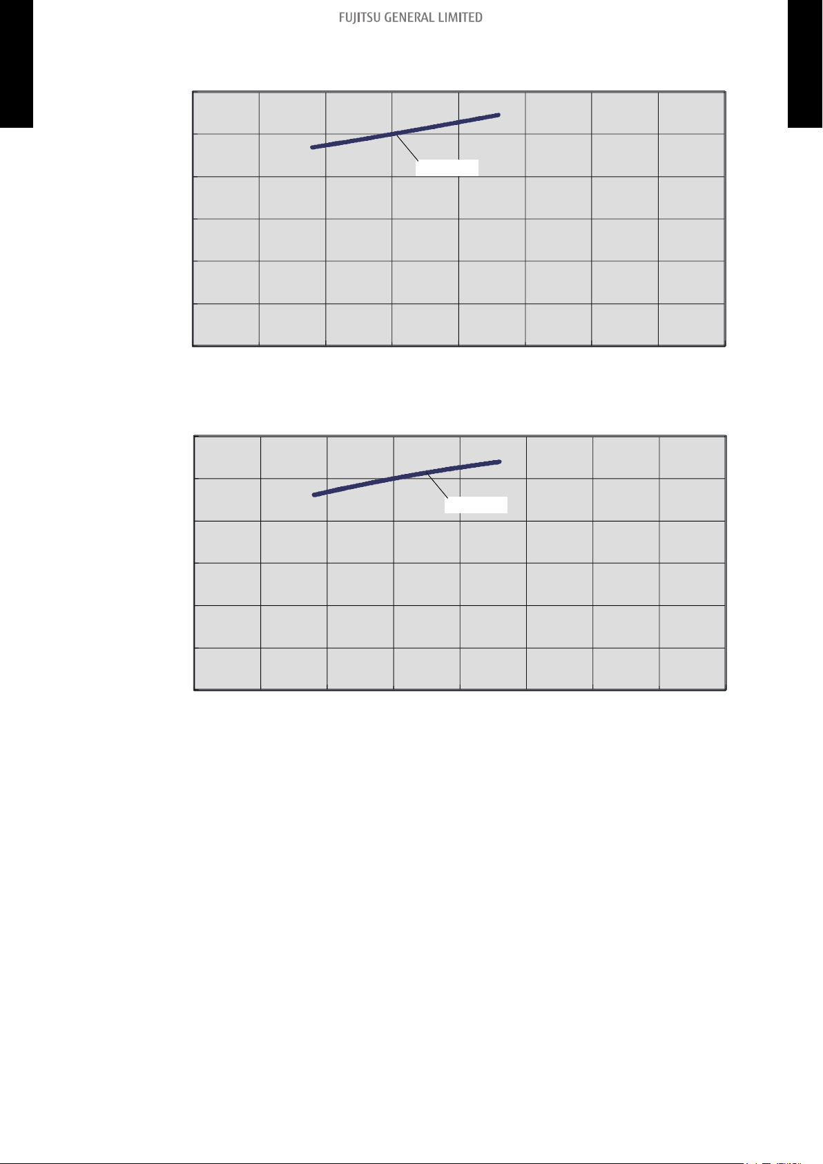
Characteristics of air volume and capacity
0
20
40
60
80
100
120
235
294
353
471
(400)
(500)
(600)
(800)
412
(700)
Capacitty
Capacity (%)
Airflow (CFM [m3/h])
0
20
40
60
80
100
120
235
294
353
471
(400)
(500)
(600)
(800)
412
(700)
Capacitty
Capacity (%)
Airflow (CFM [m3/h])
MULTI TYPE
2, 3, 4 ROOMS TYPE
• Cooling
• Heating
MULTI TYPE
2, 3, 4 ROOMS TYPE
6-1. Slim duct type 6. Fan performance
- 66 -
Page 75

¢
Hi (SP mode 09)
Hi (Normal SP)
SP mode 09
upper limit
SP mode 09
lower limit
Quiet (SP mode 09)
Normal SP
upper limit
Quiet (Normal SP)
SP mode 00
upper limit
Quiet (SP mode 00)
0.44 (110)
0.40 (100)
0.36 (90)
0.32 (80)
0.28 (70)
0.24 (60)
0.20 (50)
0.16 (40)
0.12 (30)
0.08 (20)
0.04 (10)
0 (0)
177
235
294
353
412
(300)
(400)
(500)
(600)
(700)
External static pressure (inWG [Pa])
Airflow (CFM [m3/h])
471
(800)
*1
0.44 (110)
0.40 (100)
0.36 (90)
0.32 (80)
0.28 (70)
0.24 (60)
0.20 (50)
0.16 (40)
0.12 (30)
0.08 (20)
0.04 (10)
0 (0)
177
(300)
External static pressure (inWG [Pa])
Airflow (CFM [m3/h])
Hi (SP mode 09)
Hi (SP mode 08)
Hi (SP mode 07)
Hi (SP mode 06)
Hi (SP mode 05)
Hi (SP mode 04)
Hi (SP mode 03)
Hi (Normal SP)
Hi (SP mode 02)
Hi (SP mode 01)
Hi (SP mode 00)
Available airflow rate range (High level)
*1
235
294
353
471
(400)
(500)
(600)
(800)
412
(700)
*1: Available airflow rate range when Auto louver grille (option) is installed.
Fan speed : HIGH
Vertical airflow direction louver : Up
MULTI TYPE
2, 3, 4 ROOMS TYPE
Model: ARU9RLF
MULTI TYPE
2, 3, 4 ROOMS TYPE
6-1. Slim duct type 6. Fan performance
- 67 -
Page 76

Characteristics of air volume and capacity
0
20
40
60
80
100
120
235
294
353
471
(400)
(500)
(600)
(800)
412
(700)
Capacitty
Capacity (%)
Airflow (CFM [m3/h])
0
20
40
60
80
100
120
235
294
353
471
(400)
(500)
(600)
(800)
412
(700)
Capacitty
Capacity (%)
Airflow (CFM [m3/h])
MULTI TYPE
2, 3, 4 ROOMS TYPE
• Cooling
• Heating
MULTI TYPE
2, 3, 4 ROOMS TYPE
6-1. Slim duct type 6. Fan performance
- 68 -
Page 77
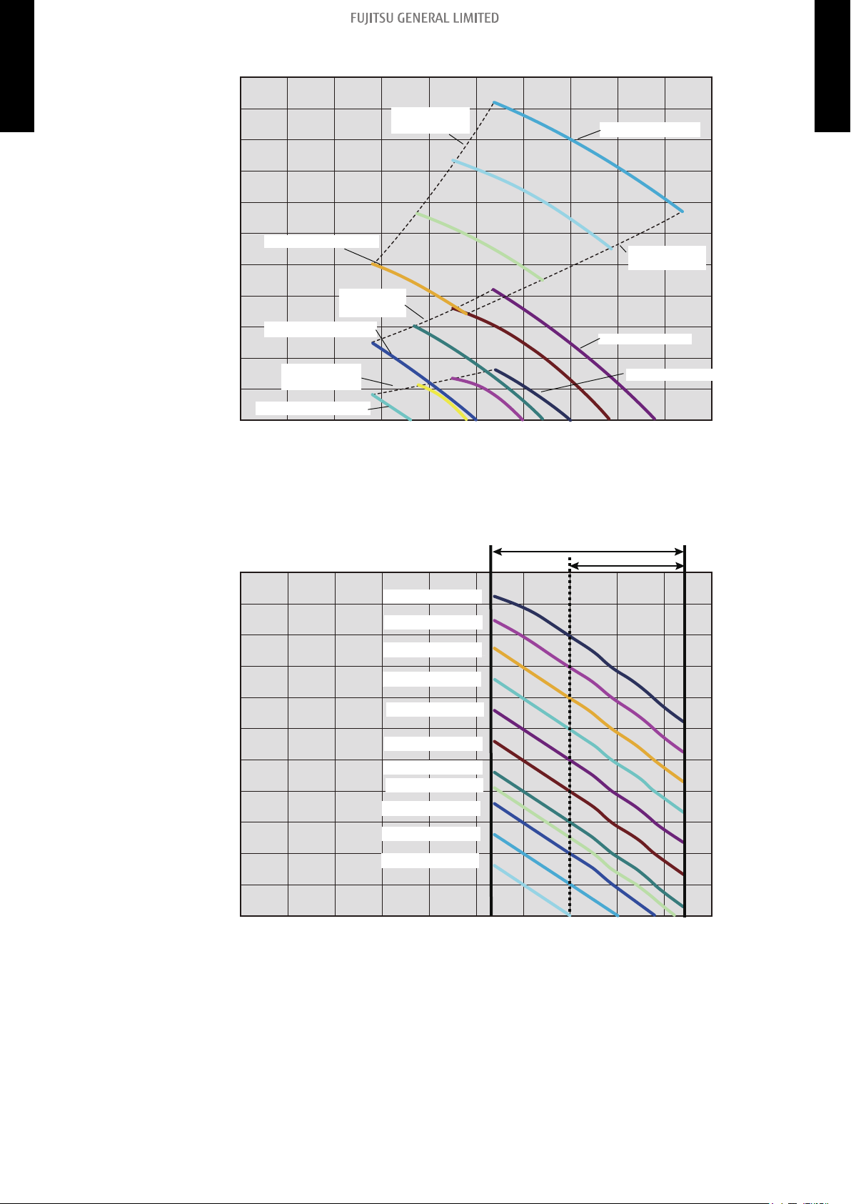
¢
Hi (SP mode 09)
Hi (Normal SP)
SP mode 09
upper limit
SP mode 09
lower limit
Quiet (SP mode 09)
Normal SP
upper limit
Quiet (Normal SP)
SP mode 00
upper limit
Quiet (SP mode 00)
0.44 (110)
0.40 (100)
0.36 (90)
0.32 (80)
0.28 (70)
0.24 (60)
0.20 (50)
0.16 (40)
0.12 (30)
0.08 (20)
0.04 (10)
0 (0)
177
235
294
353
412
(300)
(400)
(500)
(600)
(700)
External static pressure (inWG [Pa])
Airflow (CFM [m3/h])
471
(800)
Hi (SP mode 00)
0.44 (110)
0.40 (100)
0.36 (90)
0.32 (80)
0.28 (70)
0.24 (60)
0.20 (50)
0.16 (40)
0.12 (30)
0.08 (20)
0.04 (10)
0 (0)
177
235
294
353
471
(300)
(400)
(500)
(600)
(800)
External static pressure (inWG [Pa])
Airflow (CFM [m3/h])
Hi (SP mode 09)
Hi (SP mode 08)
Hi (SP mode 07)
Hi (SP mode 06)
Hi (SP mode 05)
Hi (SP mode 04)
Hi (SP mode 03)
Hi (Normal SP)
Hi (SP mode 02)
Hi (SP mode 01)
Hi (SP mode 00)
Available airflow rate range (High level)
*1
412
(700)
*1: Available airflow rate range when Auto louver grille (option) is installed.
Fan speed : HIGH
Vertical airflow direction louver : Up
MULTI TYPE
2, 3, 4 ROOMS TYPE
Model: ARU12RLF
MULTI TYPE
2, 3, 4 ROOMS TYPE
6-1. Slim duct type 6. Fan performance
- 69 -
Page 78

Characteristics of air volume and capacity
0
20
40
60
80
100
120
530
294
353
471
(900)
(500)
(600)
(800)
412
(700)
Capacitty
Capacity (%)
Airflow (CFM [m3/h])
(900)
0
20
40
60
80
100
120
530
294
353
471
(500)
(600)
(800)
412
(700)
Capacitty
Capacity (%)
Airflow (CFM [m3/h])
MULTI TYPE
2, 3, 4 ROOMS TYPE
• Cooling
• Heating
MULTI TYPE
2, 3, 4 ROOMS TYPE
6-1. Slim duct type 6. Fan performance
- 70 -
Page 79

¢
Hi (SP mode 09)
Hi (Normal SP)
SP mode 09
upper limit
SP mode 09
lower limit
Quiet (SP mode 09)
Normal SP
upper limit
Quiet (Normal SP)
SP mode 00
upper limit
Quiet (SP mode 00)
0.44 (110)
0.40 (100)
0.36 (90)
0.32 (80)
0.28 (70)
0.24 (60)
0.20 (50)
0.16 (40)
0.12 (30)
0.08 (20)
0.04 (10)
0 (0)
412
(700)
External static pressure (in.WG [Pa])
Airflow (CFM [m3/h])
Hi (SP mode 00)
530
589
647
706
(900)
(1,000)
(1,100)
(1,200)
471
(800)
353
(600)
0.44 (110)
0.40 (100)
0.36 (90)
0.32 (80)
0.28 (70)
0.24 (60)
0.20 (50)
0.16 (40)
0.12 (30)
0.08 (20)
0.04 (10)
0 (0)
External static pressure (inWG [Pa])
Airflow (CFM [m3/h])
Hi (SP mode 09)
Hi (SP mode 08)
Hi (SP mode 07)
Hi (SP mode 06)
Hi (SP mode 05)
Hi (SP mode 04)
Hi (SP mode 03)
Hi (Normal SP)
Hi (SP mode 02)
Hi (SP mode 01)
Hi (SP mode 00)
Available airflow rate range (High level)
*1
412
(700)
530
589
647
706
(900)
(1,000)
(1,100)
(1,200)
471
(800)
353
(600)
*1: Available airflow rate range when Auto louver grille (option) is installed.
Fan speed : HIGH
Vertical airflow direction louver : Up
MULTI TYPE
2, 3, 4 ROOMS TYPE
Model: ARU18RLF
MULTI TYPE
2, 3, 4 ROOMS TYPE
6-1. Slim duct type 6. Fan performance
- 71 -
Page 80

Characteristics of air volume and capacity
0
20
40
60
80
100
120
Capacitty
Capacity (%)
Airflow (CFM [m3/h])
412
(700)
530
589
647
(900)
(1,000)
(1,100)
471
(800)
0
20
40
60
80
100
120
Capacitty
Capacity (%)
Airflow (CFM [m3/h])
412
(700)
530
589
647
(900)
(1,000)
(1,100)
471
(800)
MULTI TYPE
2, 3, 4 ROOMS TYPE
• Cooling
• Heating
MULTI TYPE
2, 3, 4 ROOMS TYPE
6-1. Slim duct type 6. Fan performance
- 72 -
Page 81

¢
Hi (SP mode 05)
Hi (Normal SP)
SP mode 05
upper limit
SP mode 05
lower limit
Quiet (SP mode 05)
Normal SP
upper limit
Quiet
(Normal SP)
SP mode 00
upper limit
Quiet
(SP mode 00)
0.32 (80)
0.28 (70)
0.24 (60)
0.20 (50)
0.16 (40)
0.12 (30)
0.08 (20)
0.04 (10)
0 (0)
530
589
647
706
765
(900)
(1,000)
(1,100)
(1,200)
(1,300)
External static pressure (inWG [Pa])
Airflow (CFM [m3/h])
471
(800)
Hi (SP mode 00)
824
883
(1,400)
(1,500)
942
(1,600)
0 (0)
External static pressure (inWG [Pa])
Airflow (CFM [m3/h])
Hi (SP mode 05)
Hi (SP mode 04)
Hi (SP mode 03)
Hi (Normal SP)
Hi (SP mode 02)
Hi (SP mode 01)
Hi (SP mode 00)
Available airflow rate range (High level)
*1
530
589
647
706
765
(900)
(1,000)
(1,100)
(1,200)
(1,300)
471
(800)
824
883
(1,400)
(1,500)
942
(1,600)
0.32 (80)
0.28 (70)
0.24 (60)
0.20 (50)
0.16 (40)
0.12 (30)
0.08 (20)
0.04 (10)
*1: Available airflow rate range when Auto louver grille (option) is installed.
Fan speed : HIGH
Vertical airflow direction louver : Up
MULTI TYPE
2, 3, 4 ROOMS TYPE
Model: ARU24RLF
MULTI TYPE
2, 3, 4 ROOMS TYPE
6-1. Slim duct type 6. Fan performance
- 73 -
Page 82

Characteristics of air volume and capacity
0
20
40
60
80
100
120
Capacitty
Capacity (%)
Airflow (CFM [m3/h])
706
(1,200)
530
589
647
(900)
(1,000)
(1,100)
471
(800)
765
(1,300)
824
(1,400)
883
(1,500)
942
(1,600)
0
20
40
60
80
100
120
Capacitty
Capacity (%)
Airflow (CFM [m3/h])
706
(1,200)
530
589
647
(900)
(1,000)
(1,100)
471
(800)
765
(1,300)
824
(1,400)
883
(1,500)
942
(1,600)
MULTI TYPE
2, 3, 4 ROOMS TYPE
• Cooling
• Heating
MULTI TYPE
2, 3, 4 ROOMS TYPE
6-1. Slim duct type 6. Fan performance
- 74 -
Page 83

7. Airflow
Conversion factor:
MULTI TYPE
2, 3, 4 ROOMS TYPE
• 1 m3/h = 0.2778 l/s = 0.5886 CFM
• 3.6 m3/h = 1 l/s
• 1.699 m3/h = 1 CFM
7-1. Compact cassette type
Model Operation mode Fan speed
High 540 150 318
Cooling
AUU7RLF
Heating
Cooling
AUU9RLF
Heating
Cooling
AUU12RLF
Heating
Cooling
AUU18RLF
Heating
Med 490 136 288
Low 440 122 259
Quiet 390 108 230
High 540 150 318
Med 490 136 288
Low 440 122 259
Quiet 390 108 230
High 540 150 318
Med 490 136 288
Low 440 122 259
Quiet 390 108 230
High 540 150 318
Med 490 136 288
Low 440 122 259
Quiet 390 108 230
High 610 169 359
Med 530 147 312
Low 470 131 277
Quiet 410 114 241
High 610 169 359
Med 530 147 312
Low 470 131 277
Quiet 410 114 241
High 750 208 441
Med 610 169 359
Low 520 144 306
Quiet 410 114 241
High 800 222 471
Med 710 197 418
Low 600 167 353
Quiet 450 125 265
m3/h
Airflow
l/s CFM
MULTI TYPE
2, 3, 4 ROOMS TYPE
7-1. Compact cassette type 7. Airflow
- 75 -
Page 84

7-2. Slim duct type
MULTI TYPE
2, 3, 4 ROOMS TYPE
Model Operation mode Fan speed
High 550 153 324
Cooling
ARU7RLF
Heating
Med 490 136 288
Low 470 131 277
Quiet 440 122 259
High 550 153 324
Med 490 136 288
Low 470 131 277
Quiet 440 122 259
High 600 167 353
Cooling
ARU9RLF
Heating
Med 550 153 324
Low 500 139 294
Quiet 450 125 265
High 600 167 353
Med 550 153 324
Low 500 139 294
Quiet 450 125 265
High 650 181 383
Cooling
ARU12RLF
Heating
Med 600 167 353
Low 550 153 324
Quiet 480 133 283
High 650 181 383
Med 600 167 353
Low 550 153 324
Quiet 480 133 283
High 940 261 554
Cooling
ARU18RLF
Heating
Med 880 244 518
Low 820 227 483
Quiet 750 208 441
High 940 261 554
Med 880 244 518
Low 820 227 483
Quiet 750 208 441
High 1,330 369 783
Cooling
ARU24RLF
Heating
Med 1,240 344 730
Low 1,100 306 648
Quiet 1,030 286 607
High 1,330 369 783
Med 1,240 344 730
Low 1,100 306 648
Quiet 1,030 286 607
m3/h
Airflow
l/s CFM
MULTI TYPE
2, 3, 4 ROOMS TYPE
7-2. Slim duct type 7. Airflow
- 76 -
Page 85

7-3. Wall mounted type
MULTI TYPE
2, 3, 4 ROOMS TYPE
Model Operation mode Fan speed
High 560 156 330
Cooling
ASU7RLF1
Quiet 310 86 182
High 560 156 330
Heating
Quiet 330 92 194
High 600 167 353
Cooling
ASU9RLF1
Quiet 310 86 182
High 600 167 353
Heating
Quiet 330 92 194
High 660 183 388
Cooling
ASU12RLF1
Quiet 310 86 182
High 660 183 388
Heating
Quiet 330 92 194
High 730 203 430
Cooling
ASU15RLF1
Quiet 360 100 212
High 730 203 430
Heating
Quiet 375 104 221
High 920 256 542
Cooling
ASU18RLF
Quiet 550 153 324
High 920 256 542
Heating
Quiet 550 153 324
High 1,120 311 659
Cooling
ASU24RLF
Quiet 620 172 365
High 1,100 306 647
Heating
Quiet 620 172 365
Airflow
m3/h
l/s CFM
Med 500 139 294
Low 430 119 253
Med 500 139 294
Low 430 119 253
Med 520 144 306
Low 430 119 253
Med 520 144 306
Low 430 119 253
Med 560 156 330
Low 450 125 265
Med 560 156 330
Low 470 131 277
Med 600 167 353
Low 530 147 312
Med 615 171 362
Low 560 156 330
Med 740 206 436
Low 620 172 365
Med 740 206 436
Low 620 172 365
Med 900 250 530
Low 740 206 436
Med 900 250 530
Low 740 206 436
MULTI TYPE
2, 3, 4 ROOMS TYPE
7-3. Wall mounted type 7. Airflow
- 77 -
Page 86

MULTI TYPE
2, 3, 4 ROOMS TYPE
Model Operation mode Fan speed
Cooling
ASU7RLF
Heating
Cooling
ASU9RLF
Heating
Cooling
ASU12RLF
Heating
Cooling
ASU9RLS2
Heating
Cooling
ASU12RLS2
Heating
Cooling
ASU15RLS2
Heating
Airflow
m3/h
l/s CFM
High 560 156 330
Med 500 139 294
Low 430 119 253
Quiet 340 94 200
High 560 156 330
Med 500 139 294
Low 430 119 253
Quiet 350 97 206
High 600 167 353
Med 520 144 306
Low 430 119 253
Quiet 340 94 200
High 600 167 353
Med 520 144 306
Low 430 119 253
Quiet 350 97 206
High 660 183 388
Med 560 156 330
Low 450 125 265
Quiet 340 94 200
High 660 183 388
Med 560 156 330
Low 470 131 277
Quiet 350 97 206
High 600 167 353
Med 550 153 324
Low 470 131 277
Quiet 330 92 194
High 600 167 353
Med 550 153 324
Low 470 131 277
Quiet 330 92 194
High 660 183 388
Med 600 167 353
Low 530 147 312
Quiet 330 92 194
High 660 183 388
Med 600 167 353
Low 530 147 312
Quiet 330 92 194
High 710 197 418
Med 640 178 377
Low 570 158 336
Quiet 390 108 230
High 710 197 418
Med 640 178 377
Low 590 164 347
Quiet 430 119 253
MULTI TYPE
2, 3, 4 ROOMS TYPE
7-3. Wall mounted type 7. Airflow
- 78 -
Page 87

7-4. Floor type
MULTI TYPE
2, 3, 4 ROOMS TYPE
Model Operation mode Fan speed
High 530 147 312
Cooling
AGU9RLF
Heating
Med 440 122 259
Low 360 100 212
Quiet 270 75 159
High 530 147 312
Med 460 128 270
Low 380 106 224
Quiet 270 75 159
High 600 167 353
Cooling
AGU12RLF
Heating
Med 490 136 288
Low 380 106 224
Quiet 270 75 159
High 600 167 353
Med 510 142 300
Low 410 114 241
Quiet 270 75 159
High 650 181 383
Cooling
AGU15RLF
Heating
Med 520 144 306
Low 400 111 235
Quiet 270 75 159
High 650 181 383
Med 540 150 318
Low 430 119 253
Quiet 270 75 159
m3/h
Airflow
l/s CFM
MULTI TYPE
2, 3, 4 ROOMS TYPE
7-4. Floor type 7. Airflow
- 79 -
Page 88

8. Noise level curve
0
10
20
30
40
50
60
70
80
63 125 250 500 1,000 2,000 4,000 8,000
Octave band sound pressure level, dB: (0 dB=0.00020 μbar)
Octave band center frequency, Hz
NC-65
NC-60
NC-55
NC-50
NC-45
NC-40
NC-35
NC-30
NC-25
NC-20
NC-15
HIGH
QUIET
0
10
20
30
40
50
60
70
80
63 125 250 500 1,000 2,000 4,000 8,000
Octave band sound pressure level, dB: (0 dB=0.00020 μbar)
Octave band center frequency, Hz
NC-65
NC-60
NC-55
NC-50
NC-45
NC-40
NC-35
NC-30
NC-25
NC-20
NC-15
HIGH
QUIET
Octave band sound pressure level, dB: (0 dB=0.00020 μbar)
Octave band center frequency, Hz
0
10
20
30
40
50
60
70
80
63 125 250 500 1,000 2,000 4,000 8,000
NC-20
NC-40
NC-50
NC-60
NC-30
NC-15
NC-25
NC-35
NC-45
NC-55
NC-65
HIGH
QUIET
Octave band sound pressure level, dB: (0 dB=0.00020 μbar)
Octave band center frequency, Hz
0
10
20
30
40
50
60
70
80
63 125 250 500 1,000 2,000 4,000 8,000
NC-20
NC-40
NC-50
NC-60
NC-30
NC-15
NC-25
NC-35
NC-45
NC-55
NC-65
HIGH
QUIET
MULTI TYPE
8-1. Compact cassette type
2, 3, 4 ROOMS TYPE
¢
Cooling
Model: AUU7RLF
Heating
MULTI TYPE
2, 3, 4 ROOMS TYPE
Model: AUU9RLF
¢
Cooling
8-1. Compact cassette type 8. Noise level curve
Heating
- 80 -
Page 89

Model: AUU12RLF
Octave band sound pressure level, dB: (0 dB=0.00020 μbar)
Octave band center frequency, Hz
0
10
20
30
40
50
60
70
80
63 125 250 500 1,000 2,000 4,000 8,000
NC-20
NC-40
NC-50
NC-60
NC-30
NC-15
NC-25
NC-35
NC-45
NC-55
NC-65
HIGH
QUIET
Octave band sound pressure level, dB: (0 dB=0.00020 μbar)
Octave band center frequency, Hz
0
10
20
30
40
50
60
70
80
63 125 250 500 1,000 2,000 4,000 8,000
NC-20
NC-40
NC-50
NC-60
NC-30
NC-15
NC-25
NC-35
NC-45
NC-55
NC-65
HIGH
QUIET
Octave band sound pressure level, dB: (0 dB=0.00020 μbar)
Octave band center frequency, Hz
0
10
20
30
40
50
60
70
80
63 125 250 500 1,000 2,000 4,000 8,000
NC-20
NC-40
NC-50
NC-60
NC-30
NC-15
NC-25
NC-35
NC-45
NC-55
NC-65
HIGH
QUIET
Octave band sound pressure level, dB: (0 dB=0.00020 μbar)
Octave band center frequency, Hz
NC-20
NC-40
NC-50
NC-60
NC-30
NC-15
NC-25
NC-35
NC-45
NC-55
NC-65
HIGH
QUIET
0
10
20
30
40
50
60
70
80
63 125 250 500 1,000 2,000 4,000 8,000
¢
Cooling
MULTI TYPE
2, 3, 4 ROOMS TYPE
Heating
MULTI TYPE
2, 3, 4 ROOMS TYPE
Model: AUU18RLF
¢
Cooling
8-1. Compact cassette type 8. Noise level curve
Heating
- 81 -
Page 90

8-2. Slim duct type
0
10
20
30
40
50
60
70
80
63 125 250 500 1,000 2,000 4,000 8,000
Octave band sound pressure level, dB: (0 dB=0.00020 μbar)
Octave band center frequency, Hz
NC-65
NC-60
NC-55
NC-50
NC-45
NC-40
NC-35
NC-30
NC-25
NC-20
NC-15
HIGH
QUIET
0
10
20
30
40
50
60
70
80
63 125 250 500 1,000 2,000 4,000 8,000
Octave band sound pressure level, dB: (0 dB=0.00020 μbar)
Octave band center frequency, Hz
NC-65
NC-60
NC-55
NC-50
NC-45
NC-40
NC-35
NC-30
NC-25
NC-20
NC-15
HIGH
QUIET
0
10
20
30
40
50
60
70
80
63 125 250 500 1,000 2,000 4,000 8,000
Octave band sound pressure level, dB: (0 dB=0.00020 μbar)
Octave band center frequency, Hz
NC-20
NC-40
NC-50
NC-60
NC-30
NC-15
NC-25
NC-35
NC-45
NC-55
NC-65
HIGH
QUIET
0
10
20
30
40
50
60
70
80
63 125 250 500 1,000 2,000 4,000 8,000
Octave band sound pressure level, dB: (0 dB=0.00020 μbar)
Octave band center frequency, Hz
NC-20
NC-40
NC-50
NC-60
NC-30
NC-15
NC-25
NC-35
NC-45
NC-55
NC-65
HIGH
QUIET
¢
MULTI TYPE
2, 3, 4 ROOMS TYPE
Cooling
Model: ARU7RLF
Heating
MULTI TYPE
2, 3, 4 ROOMS TYPE
Model: ARU9RLF
¢
Cooling
8-2. Slim duct type 8. Noise level curve
Heating
- 82 -
Page 91

Model: ARU12RLF
0
10
20
30
40
50
60
70
80
63 125 250 500 1,000 2,000 4,000 8,000
Octave band sound pressure level, dB: (0 dB=0.00020 μbar)
Octave band center frequency, Hz
NC-20
NC-40
NC-50
NC-60
NC-30
NC-15
NC-25
NC-35
NC-45
NC-55
NC-65
HIGH
QUIET
0
10
20
30
40
50
60
70
80
63 125 250 500 1,000 2,000 4,000 8,000
Octave band sound pressure level, dB: (0 dB=0.00020 μbar)
Octave band center frequency, Hz
NC-20
NC-40
NC-50
NC-60
NC-30
NC-15
NC-25
NC-35
NC-45
NC-55
NC-65
HIGH
QUIET
0
10
20
30
40
50
60
70
80
63 125 250 500 1,000 2,000 4,000 8,000
Octave band sound pressure level, dB: (0 dB=0.00020 μbar)
Octave band center frequency, Hz
NC-20
NC-40
NC-50
NC-60
NC-30
NC-15
NC-25
NC-35
NC-45
NC-55
NC-65
HIGH
QUIET
0
10
20
30
40
50
60
70
80
63 125 250 500 1,000 2,000 4,000 8,000
Octave band sound pressure level, dB: (0 dB=0.00020 μbar)
Octave band center frequency, Hz
NC-20
NC-40
NC-50
NC-60
NC-30
NC-15
NC-25
NC-35
NC-45
NC-55
NC-65
HIGH
QUIET
¢
Cooling
MULTI TYPE
2, 3, 4 ROOMS TYPE
Heating
MULTI TYPE
2, 3, 4 ROOMS TYPE
Model: ARU18RLF
¢
Cooling
Heating
8-2. Slim duct type 8. Noise level curve
- 83 -
Page 92

Model: ARU24RLF
0
10
20
30
40
50
60
70
80
63 125 250 500 1,000 2,000 4,000 8,000
Octave band sound pressure level, dB: (0 dB=0.00020 μbar)
Octave band center frequency, Hz
NC-65
NC-60
NC-55
NC-50
NC-45
NC-40
NC-35
NC-30
NC-25
NC-20
NC-15
HIGH
QUIET
0
10
20
30
40
50
60
70
80
63 125 250 500 1,000 2,000 4,000 8,000
Octave band sound pressure level, dB: (0 dB=0.00020 μbar)
Octave band center frequency, Hz
NC-65
NC-60
NC-55
NC-50
NC-45
NC-40
NC-35
NC-30
NC-25
NC-20
NC-15
HIGH
QUIET
¢
Cooling
MULTI TYPE
2, 3, 4 ROOMS TYPE
Heating
MULTI TYPE
2, 3, 4 ROOMS TYPE
8-2. Slim duct type 8. Noise level curve
- 84 -
Page 93

8-3. Wall mounted type
0
10
20
30
40
50
60
70
80
63 125 250 500 1,000 2,000 4,000 8,000
Octave band sound pressure level, dB: (0 dB=0.00020 μbar)
Octave band center frequency, Hz
NC-65
NC-60
NC-55
NC-50
NC-45
NC-40
NC-35
NC-30
NC-25
NC-20
NC-15
QUIET
HIGH
0
10
20
30
40
50
60
70
80
63 125 250 500 1,000 2,000 4,000 8,000
Octave band sound pressure level, dB: (0 dB=0.00020 μbar)
Octave band center frequency, Hz
NC-65
NC-60
NC-55
NC-50
NC-45
NC-40
NC-35
NC-30
NC-25
NC-20
NC-15
QUIET
HIGH
0
10
20
30
40
50
60
70
80
63 125 250 500 1,000 2,000 4,000 8,000
Octave band sound pressure level, dB: (0 dB=0.00020 μbar)
Octave band center frequency, Hz
NC-65
NC-60
NC-55
NC-50
NC-45
NC-40
NC-35
NC-30
NC-25
NC-20
NC-15
QUIET
HIGH
-
0
10
20
30
40
50
60
70
80
63 125 250 500 1,000 2,000 4,000 8,000
Octave band sound pressure level, dB: (0 dB=0.00020 μbar)
Octave band center frequency, Hz
NC-65
NC-60
NC-55
NC-50
NC-45
NC-40
NC-35
NC-30
NC-25
NC-20
NC-15
QUIET
HIGH
¢
MULTI TYPE
2, 3, 4 ROOMS TYPE
Cooling
Model: ASU7RLF1
Heating
MULTI TYPE
2, 3, 4 ROOMS TYPE
Model: ASU9RLF1
¢
Cooling
8-3. Wall mounted type 8. Noise level curve
Heating
- 85 -
Page 94

Model: ASU12RLF1
0
10
20
30
40
50
60
70
80
63 125 250 500 1,000 2,000 4,000 8,000
Octave band sound pressure level, dB: (0 dB=0.00020 μbar)
Octave band center frequency, Hz
NC-65
NC-60
NC-55
NC-50
NC-45
NC-40
NC-35
NC-30
NC-25
NC-20
NC-15
QUIET
HIGH
0
10
20
30
40
50
60
70
80
63 125 250 500 1,000 2,000 4,000 8,000
Octave band sound pressure level, dB: (0 dB=0.00020 μbar)
Octave band center frequency, Hz
NC-65
NC-60
NC-55
NC-50
NC-45
NC-40
NC-35
NC-30
NC-25
NC-20
NC-15
QUIET
HIGH
0
10
20
30
40
50
60
70
80
63 125 250 500 1,000 2,000 4,000 8,000
Octave band sound pressure level, dB: (0 dB=0.00020 μbar)
Octave band center frequency, Hz
NC-65
NC-60
NC-55
NC-50
NC-45
NC-40
NC-35
NC-30
NC-25
NC-20
NC-15
QUIET
HIGH
0
10
20
30
40
50
60
70
80
63 125 250 500 1,000 2,000 4,000 8,000
Octave band sound pressure level, dB: (0 dB=0.00020 μbar)
Octave band center frequency, Hz
NC-65
NC-60
NC-55
NC-50
NC-45
NC-40
NC-35
NC-30
NC-25
NC-20
NC-15
QUIET
HIGH
¢
Cooling
MULTI TYPE
2, 3, 4 ROOMS TYPE
Heating
MULTI TYPE
2, 3, 4 ROOMS TYPE
Model: ASU15RLF1
¢
Cooling
8-3. Wall mounted type 8. Noise level curve
Heating
- 86 -
Page 95

Model: ASU7RLF
0
10
20
30
40
50
60
70
80
63 125 250 500 1,000 2,000 4,000 8,000
Octave band sound pressure level, dB: (0 dB=0.00020 μbar)
Octave band center frequency, Hz
NC-65
NC-60
NC-55
NC-50
NC-45
NC-40
NC-35
NC-30
NC-25
NC-20
NC-15
QUIET
HIGH
0
10
20
30
40
50
60
70
80
63 125 250 500 1,000 2,000 4,000 8,000
Octave band sound pressure level, dB: (0 dB=0.00020 μbar)
Octave band center frequency, Hz
NC-65
NC-60
NC-55
NC-50
NC-45
NC-40
NC-35
NC-30
NC-25
NC-20
NC-15
QUIET
HIGH
0
10
20
30
40
50
60
70
80
63 125 250 500 1,000 2,000 4,000 8,000
Octave band sound pressure level, dB: (0 dB=0.00020 μbar)
Octave band center frequency, Hz
NC-65
NC-60
NC-55
NC-50
NC-45
NC-40
NC-35
NC-30
NC-25
NC-20
NC-15
QUIET
HIGH
0
10
20
30
40
50
60
70
80
63 125 250 500 1,000 2,000 4,000 8,000
Octave band sound pressure level, dB: (0 dB=0.00020 μbar)
Octave band center frequency, Hz
NC-65
NC-60
NC-55
NC-50
NC-45
NC-40
NC-35
NC-30
NC-25
NC-20
NC-15
QUIET
HIGH
¢
Cooling
MULTI TYPE
2, 3, 4 ROOMS TYPE
Heating
MULTI TYPE
2, 3, 4 ROOMS TYPE
Model: ASU9RLF
¢
Cooling
Heating
8-3. Wall mounted type 8. Noise level curve
- 87 -
Page 96

Model: ASU12RLF
0
10
20
30
40
50
60
70
80
63 125 250 500 1,000 2,000 4,000 8,000
Octave band sound pressure level, dB: (0 dB=0.00020 μbar)
Octave band center frequency, Hz
NC-65
NC-60
NC-55
NC-50
NC-45
NC-40
NC-35
NC-30
NC-25
NC-20
NC-15
QUIET
HIGH
0
10
20
30
40
50
60
70
80
63 125 250 500 1,000 2,000 4,000 8,000
Octave band sound pressure level, dB: (0 dB=0.00020 μbar)
Octave band center frequency, Hz
NC-65
NC-60
NC-55
NC-50
NC-45
NC-40
NC-35
NC-30
NC-25
NC-20
NC-15
QUIET
HIGH
0
10
20
30
40
50
60
70
80
63 125 250 500 1,000 2,000 4,000 8,000
Octave band sound pressure level, dB: (0 dB=0.00020 μbar)
Octave band center frequency, Hz
NC-65
NC-60
NC-55
NC-50
NC-45
NC-40
NC-35
NC-30
NC-25
NC-20
NC-15
QUIET
HIGH
0
10
20
30
40
50
60
70
80
63 125 250 500 1,000 2,000 4,000 8,000
Octave band sound pressure level, dB: (0 dB=0.00020 μbar)
Octave band center frequency, Hz
NC-65
NC-60
NC-55
NC-50
NC-45
NC-40
NC-35
NC-30
NC-25
NC-20
NC-15
QUIET
HIGH
¢
Cooling
MULTI TYPE
2, 3, 4 ROOMS TYPE
Heating
MULTI TYPE
2, 3, 4 ROOMS TYPE
Model: ASU9RLS2
¢
Cooling
8-3. Wall mounted type 8. Noise level curve
Heating
- 88 -
Page 97

Model: ASU12RLS2
0
10
20
30
40
50
60
70
80
63 125 250 500 1,000 2,000 4,000 8,000
Octave band sound pressure level, dB: (0 dB=0.00020 μbar)
Octave band center frequency, Hz
NC-65
NC-60
NC-55
NC-50
NC-45
NC-40
NC-35
NC-30
NC-25
NC-20
NC-15
QUIET
HIGH
0
10
20
30
40
50
60
70
80
63 125 250 500 1,000 2,000 4,000 8,000
Octave band sound pressure level, dB: (0 dB=0.00020 μbar)
Octave band center frequency, Hz
NC-65
NC-60
NC-55
NC-50
NC-45
NC-40
NC-35
NC-30
NC-25
NC-20
NC-15
High
Quiet
0
10
20
30
40
50
60
70
80
63 125 250 500 1,000 2,000 4,000 8,000
Octave band sound pressure level, dB: (0 dB=0.00020 μbar)
Octave band center frequency, Hz
NC-65
NC-60
NC-55
NC-50
NC-45
NC-40
NC-35
NC-30
NC-25
NC-20
NC-15
QUIET
HIGH
0
10
20
30
40
50
60
70
80
63 125 250 500 1,000 2,000 4,000 8,000
Octave band sound pressure level, dB: (0 dB=0.00020 μbar)
Octave band center frequency, Hz
NC-65
NC-60
NC-55
NC-50
NC-45
NC-40
NC-35
NC-30
NC-25
NC-20
NC-15
QUIET
HIGH
¢
Cooling
MULTI TYPE
2, 3, 4 ROOMS TYPE
Heating
MULTI TYPE
2, 3, 4 ROOMS TYPE
Model: ASU15RLS2
¢
Cooling
Heating
8-3. Wall mounted type 8. Noise level curve
- 89 -
Page 98

Model: ASU18RLF
0
10
20
30
40
50
60
70
80
63 125 250 500 1,000 2,000 4,000 8,000
Octave band sound pressure level, dB: (0 dB=0.00020 μbar)
Octave band center frequency, Hz
NC-65
NC-60
NC-55
NC-50
NC-45
NC-40
NC-35
NC-30
NC-25
NC-20
NC-15
QUIET
HIGH
0
10
20
30
40
50
60
70
80
63 125 250 500 1,000 2,000 4,000 8,000
Octave band sound pressure level, dB: (0 dB=0.00020 μbar)
Octave band center frequency, Hz
NC-65
NC-60
NC-55
NC-50
NC-45
NC-40
NC-35
NC-30
NC-25
NC-20
NC-15
QUIET
HIGH
0
10
20
30
40
50
60
70
80
63 125 250 500 1,000 2,000 4,000 8,000
Octave band sound pressure level, dB: (0 dB=0.00020 μbar)
Octave band center frequency, Hz
NC-65
NC-60
NC-55
NC-50
NC-45
NC-40
NC-35
NC-30
NC-25
NC-20
NC-15
QUIET
HIGH
0
10
20
30
40
50
60
70
80
63 125 250 500 1,000 2,000 4,000 8,000
Octave band sound pressure level, dB: (0 dB=0.00020 μbar)
Octave band center frequency, Hz
NC-65
NC-60
NC-55
NC-50
NC-45
NC-40
NC-35
NC-30
NC-25
NC-20
NC-15
QUIET
HIGH
¢
Cooling
MULTI TYPE
2, 3, 4 ROOMS TYPE
Heating
MULTI TYPE
2, 3, 4 ROOMS TYPE
Model: ASU24RLF
¢
Cooling
8-3. Wall mounted type 8. Noise level curve
Heating
- 90 -
Page 99

8-4. Floor type
0
10
20
30
40
50
60
70
80
63 125 250 500 1,000 2,000 4,000 8,000
Octave band sound pressure level, dB: (0 dB=0.00020 μbar)
Octave band center frequency, Hz
NC-65
NC-60
NC-55
NC-50
NC-45
NC-40
NC-35
NC-30
NC-25
NC-20
NC-15
HIGH
QUIET
0
10
20
30
40
50
60
70
80
63 125 250 500 1,000 2,000 4,000 8,000
Octave band sound pressure level, dB: (0 dB=0.00020 μbar)
Octave band center frequency, Hz
NC-65
NC-60
NC-55
NC-50
NC-45
NC-40
NC-35
NC-30
NC-25
NC-20
NC-15
HIGH
QUIET
0
10
20
30
40
50
60
70
80
63 125 250 500 1,000 2,000 4,000 8,000
Octave band sound pressure level, dB: (0 dB=0.00020 μbar)
Octave band center frequency, Hz
NC-65
NC-60
NC-55
NC-50
NC-45
NC-40
NC-35
NC-30
NC-25
NC-20
NC-15
HIGH
QUIET
0
10
20
30
40
50
60
70
80
63 125 250 500 1,000 2,000 4,000 8,000
Octave band sound pressure level, dB: (0 dB=0.00020 μbar)
Octave band center frequency, Hz
NC-65
NC-60
NC-55
NC-50
NC-45
NC-40
NC-35
NC-30
NC-25
NC-20
NC-15
HIGH
QUIET
¢
MULTI TYPE
2, 3, 4 ROOMS TYPE
Cooling
Model: AGU9RLF
Heating
MULTI TYPE
2, 3, 4 ROOMS TYPE
Model: AGU12RLF
¢
Cooling
Heating
8-4. Floor type 8. Noise level curve
- 91 -
Page 100

Model: AGU15RLF
0
10
20
30
40
50
60
70
80
63 125 250 500 1,000 2,000 4,000 8,000
Octave band sound pressure level, dB: (0 dB=0.00020 μbar)
Octave band center frequency, Hz
NC-65
NC-60
NC-55
NC-50
NC-45
NC-40
NC-35
NC-30
NC-25
NC-20
NC-15
HIGH
QUIET
0
10
20
30
40
50
60
70
80
63 125 250 500 1,000 2,000 4,000 8,000
Octave band sound pressure level, dB: (0 dB=0.00020 μbar)
Octave band center frequency, Hz
NC-65
NC-60
NC-55
NC-50
NC-45
NC-40
NC-35
NC-30
NC-25
NC-20
NC-15
HIGH
QUIET
¢
Cooling
MULTI TYPE
2, 3, 4 ROOMS TYPE
Heating
MULTI TYPE
2, 3, 4 ROOMS TYPE
8-4. Floor type 8. Noise level curve
- 92 -
 Loading...