

Page 1
AIR CONDITIONER
Multi : 2rooms type
3rooms type
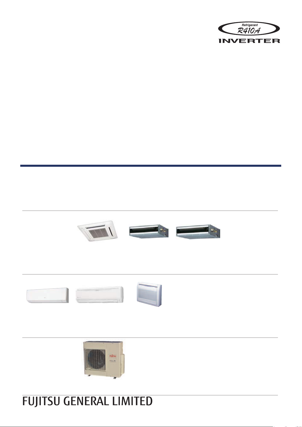
DESIGN & TECHNICAL MANUAL
for Extra Cold Climate Area
INDOOR
ASU7RLF1
ASU9RLF1
ASU12RLF1
OUTDOOR
AUU7RLF
AUU9RLF
AUU12RLF
AUU18RLF
ASU18RLF AGU9RLF
AOU18RLXFZH
AOU24RLXFZH
ARU7RLF
ARU9RLF
ARU12RLF
AGU12RLF
AGU15RLF
ARU18RLF
Page 2

1. INDOOR UNIT
COMPACT
CASSETTE TYPE :
AUU7RLF
AUU9RLF
AUU12RLF
AUU18RLF
WALL MOUNTED TYPE :
ASU7RLF1
ASU9RLF1
ASU12RLF1
ASU18RLF
SLIM DUCT TYPE :
ARU7RLF
ARU9RLF
ARU12RLF
ARU18RLF
FLOOR TYPE :
AGU9RLF
AGU12RLF
AGU15RLF
DTR_MU040E_01
2015.01.30
Page 3

CONTENTS
MULTI TYPE
2, 3 ROOMS TYPE
MULTI TYPE
2, 3 ROOMS TYPE
1. INDOOR UNIT
1. FEATURES
1-1. INDOOR UNIT
1-1-1. COMPACT CASSETTE TYPE
1-1-2. SLIM DUCT TYPE
1-1-3. WALL MOUNTED TYPE
1-1-4. FLOOR TYPE
1-2. OUTDOOR UNIT
1-3. LINE UP
...........................................................................................................01 - 01
....................................................................................................01 - 01
......................................................................................01 - 02
............................................................................................01 - 05
...............................................................................................01 - 06
.............................................................................................................. 01 - 07
2. REMOTE CONTROLLER
2-1. WIRELESS REMOTE CONTROLLER
2-2. WIRED REMOTE CONTROLLER
(For Compact cassette type, Slim duct type)
3. SPECIFICATIONS
3-1. COMPACT CASSETTE TYPE
3-2. SLIM DUCT TYPE
3-3. WALL MOUNTED TYPE
...........................................................................................01 - 23
............................................................................................. 01 - 24
..................................................................................01 - 25
...................................................................01 - 01
........................................................................... 01 - 03
.......................................................................... 01 - 09
........................................................... 01 - 09
...........................................01 - 17
.........................................................................01 - 23
3-4. FLOOR TYPE
4. DIMENSIONS
4-1. COMPACT CASSETTE TYPE
4-2. SLIM DUCT TYPE
4-3. WALL MOUNTED TYPE
4-4. FLOOR TYPE
5. WIRING DIAGRAMS
5-1. COMPACT CASSETTE TYPE
5-2. SLIM DUCT TYPE
5-3. WALL MOUNTED TYPE
5-4. FLOOR TYPE
..................................................................................................... 01 - 27
...................................................................................................... 01 - 28
.........................................................................01 - 28
............................................................................................. 01 - 30
..................................................................................01 - 34
..................................................................................................... 01 - 38
.....................................................................................01 - 39
.........................................................................01 - 39
............................................................................................. 01 - 40
..................................................................................01 - 41
..................................................................................................... 01 - 43
6. AIR VELOCITY AND TEMPERATURE DISTRIBUTIONS
6-1. COMPACT CASSETTE TYPE
6-2. SLIM DUCT TYPE with Auto louver grille kit
6-3. WALL MOUNTED TYPE
........................................................................01 - 44
............................................01 - 50
.................................................................................. 01 - 58
01 - 44
6-4. FLOOR TYPE
..................................................................................................... 01 - 62
7. FAN PERFORMANCE CURVE
7-1. SLIM DUCT TYPE
............................................................................................. 01 - 63
............................................................. 01 - 63
Page 4

CONTENTS
MULTI TYPE
2, 3 ROOMS TYPE
MULTI TYPE
2, 3 ROOMS TYPE
1. INDOOR UNIT
8. AIRFLOW
9. NOISE LEVEL CURVE
9-1. COMPACT CASSETTE TYPE
9-2. SLIM DUCT TYPE
9-3. WALL MOUNTED TYPE
9-4. FLOOR TYPE
9-5. SOUND LEVEL CHECK POINT
............................................................................................................... 01 - 71
................................................................................01 - 73
.........................................................................01 - 73
............................................................................................. 01 - 75
..................................................................................01 - 77
..................................................................................................... 01 - 80
.....................................................................01 - 82
10. ELECTRIC CHARACTERISTICS
11. SAFETY DEVICES
12. EXTERNAL INPUT & OUTPUT
12-1. EXTERNAL INPUT
12-2. EXTERNAL OUTPUT
13. FUNCTION SETTINGS
13-1. INDOOR UNIT (setting by jumper wire)
.......................................................................................... 01 - 86
............................................................01 - 87
............................................................................................ 01 - 87
....................................................................................... 01 - 89
................................................................................ 01 - 93
........................................................ 01 - 85
...................................................... 01 - 93
13-2. INDOOR UNIT (setting by wireless remote controller)
13-2-1. UTY-LNHUM
13-2-2. AR-REG1U
13-3. INDOOR UNIT (setting by wired remote controller)
13-3-1. UTY-RNNUM
13-4. INDOOR UNIT (setting by simple remote controller)
13-5. FUNCTION DETAILS
13-6. WIRED REMOTE CONTROLLER
13-7. SIMPLE REMOTE CONTROLLER
14. OPTIONAL PARTS
14-1. CONTROLLER
14-2. CASSETTE GRILLE
14-3. OTHERS
...........................................................................................................01 - 126
..............................................................................................01 - 95
............................................................................................... 01 - 100
............................................................................................ 01 - 106
.......................................................................................01 - 113
.................................................................01 - 118
............................................................... 01 - 121
....................................................................................... 01 - 124
................................................................................................01 - 124
.......................................................................................01 - 125
15. INSTALLATION PRECAUTIONS
15-1. INDOOR UNIT INSTALLATION PRECAUTIONS
..........................01 - 94
.............................. 01 - 105
............................01 - 109
.......................................................01 - 128
...................................... 01 - 128
Page 5
FEATURES1.
+
2 stage
22-7/16in. (570mm)
22-7/16in. (570mm)
27-9/16in. (700mm)
A
B
C
D
2
3
1
INDOOR UNIT1-1.
MULTI TYPE
2, 3 ROOMS TYPE
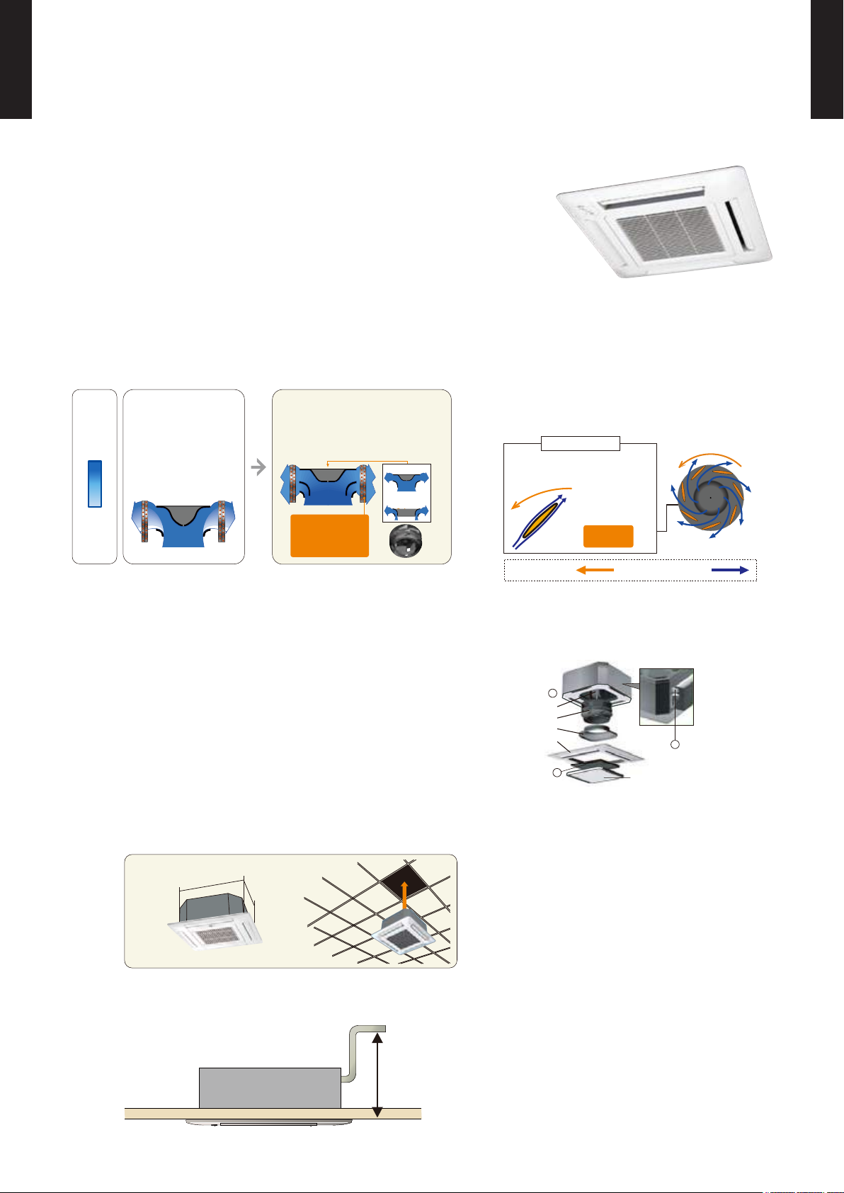
MODELS : AUU7RLF, AUU9RLF, AUU12RLF, AUU18RLF
COMPACT CASSETTE TYPE1-1-1.
FEATURES
2-stage turbo fan
z
Quiet quality
z
Optimization of wing form (laminar
Wind
velocity
Fast
Slow
High efciency design by 2 stage structure
Previous turbo fan
In the case of a
conventional fan, the air
outlet range was narrow
as the air ow moved to
the motor side which
meant the velocity of air
passing through the heat
exchanger was uneven.
2-stage turbo fan
A evenly spread air distribution across
the heat exchanger is possible due
to the new 2 stage turbo fan which
produces two separate air ow
streams.
1-stage
2-stage
Heat exchange
efciency:
20%UP
wing type) and wing number (7 blades
each)
Designed by CFD- analysis (uid) simulations
Laminar wing
Airow runs through smoothly
along the laminar wing
No airow separation
Quiet
Spin direction
Airow direction
Quiet
Adoption of laminar wing
MULTI TYPE
2, 3 ROOMS TYPE
Easy maintenance
z
Maintenance of fan motor and fan
Maintenance of the fan motor and fan can be done easily after taking off the panel as the bell mouth of the fan
can be removed easily.
A : Fan motor B : 2-stage turbo fan
C : Bell-mouth D : Panel
Long life lter
: standard equipment
Adaptation of transparent drainage parts
During installation, maintenance and operation, the drain pump and
kit can be checked easily.
Compact design
z
Grille cover
Easy installation by taking off ceiling panel of 23-5/8in. x 23-5/8in.(600mm x 600mm) size
High lift drain pump
z
- (01 - 01) -
Page 6
MULTI TYPE
Height
Drain pump built-in
7-13/16 in.
(198mm)
Max.
33-7/16 in.
(850mm)
0
[in.WG (Pa )]
Air flow rate
Static pressure range
[CFM (m3/h)]
0.36 (90)
2, 3 ROOMS TYPE
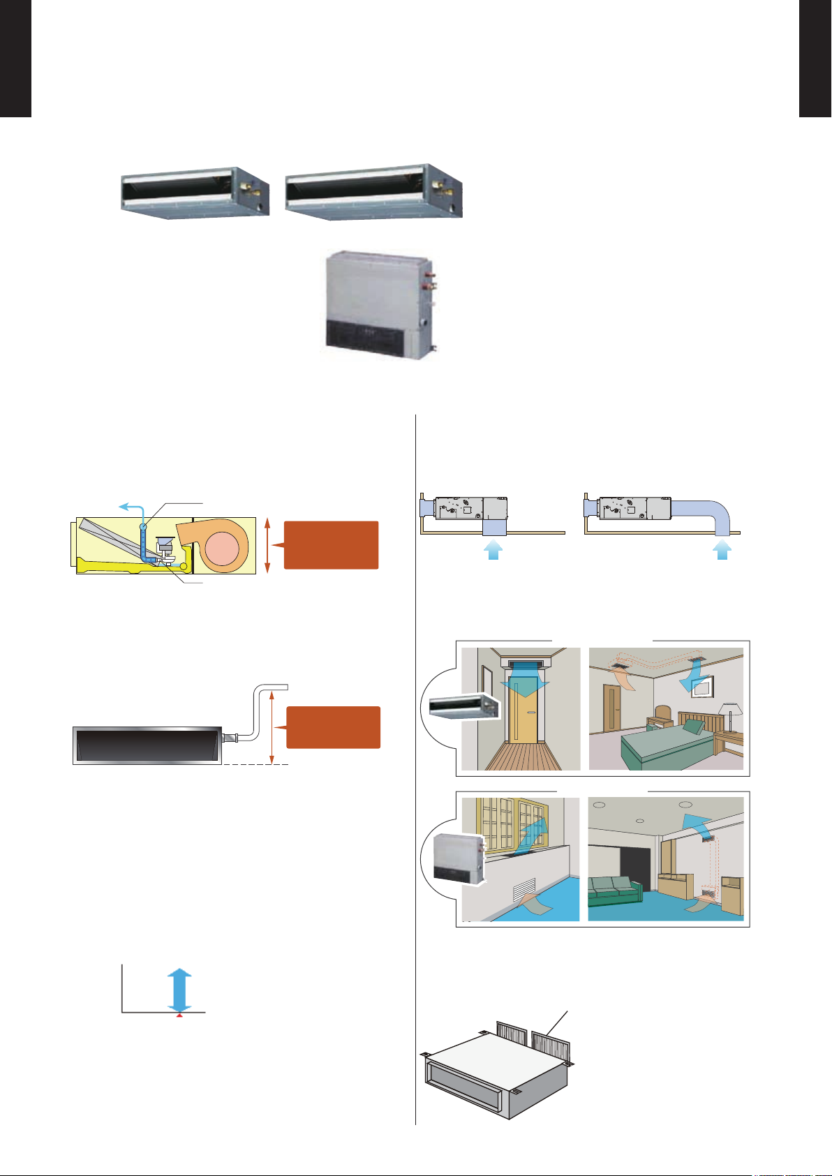
MODELS : ARU7RLF, ARU9RLF, ARU12RLF, ARU18RLF
SLIM DUCT TYPE1-1-2.
MULTI TYPE
2, 3 ROOMS TYPE
Slim design and wide range of static
pressure for exible installation.
FEATURES
Slim design
z
This model is slim design, it can install at
the place where a ceiling is narrow.
Drain por t
Drain pump
Compact design
z
Condensate lift-up to 33-7/16in. (850mm)
Drain hose is standard accessory
Selectable with a wide range of
z
static pressure
Air - intake
z
Air intake direction can be selected to
match the installation site.
Bottom side Back side
Flexible installation
z
Ceiling concealed
Wall concealed
By using DC fan motor, it is possible
to change of static pressure range 0 to
0.36in. WG (0 to 90Pa). The change of
static pressure range is possible by remote
controller.
- (01 - 02) -
Filter (Accessory)
z
Filter (ARU07/09/12/18: 2pcs.)
Page 7
MULTI TYPE
“MIN. HEAT”
Button ON
Indoor unit
operation START
68
°F
(20°C)
50
°F
(10°C)
2, 3 ROOMS TYPE
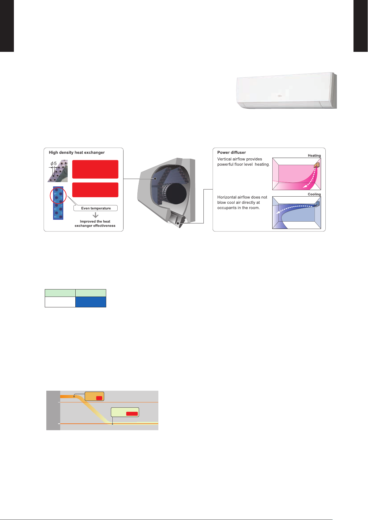
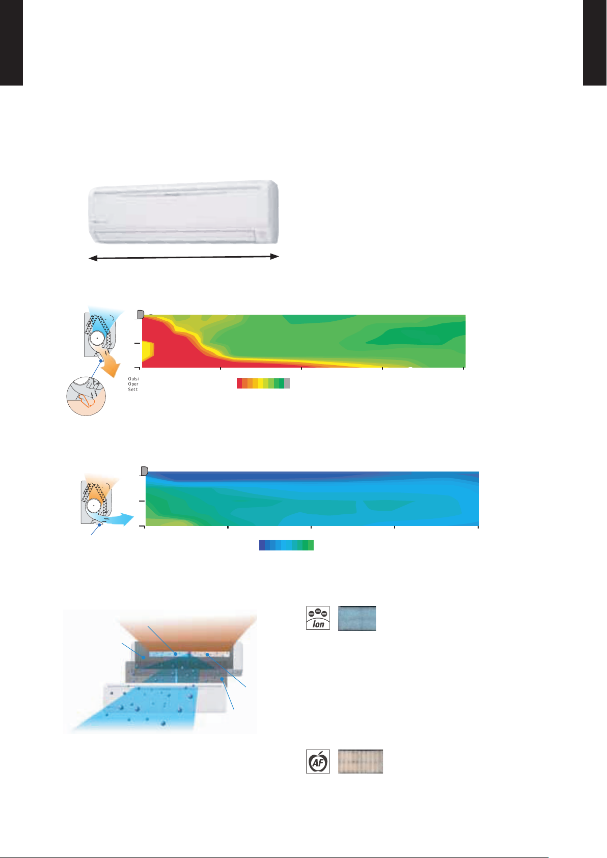
MODELS : ASU7RLF1, ASU9RLF1, ASU12RLF1
FEATURES
WALL MOUNTED TYPE 1-1-3.
MULTI TYPE
2, 3 ROOMS TYPE
High efcient compact design
z
Making the tube thin:
0.276inch (7mm)
Thin:
Volume reduction of heat
exchanger:
Quiet operation
z
▼
0.197inch (5mm)
30%
More comfortable airow
z
INDOOR UNIT
Airow mode can be set in 4 steps and more detailed airow setting is possible.
21dB only at cooling operation (22dB at heating operation).
Fan speed Noise level
dB(A)
Quiet
21
(ASU7/9/12RLF1)
MIN. HEAT Operation
z
*Only available with Wireless RC.
The room temperature can be set to go no lower than 50°F (10°C),
thus ensuring that the room does not get too cold when not occupied
Caution)
When the room temperature is higher than 50°F (10°C), “ •
temperature at 50°F (10°C) when the temperature drops below 50°F (10°C).
MIN. HEAT
When “ •
Powerful operation
z
” operation stops, the room set temperature quickly returns to the preset temperature.
*Only available with Wireless RC.
MIN. HEAT
” operation does not start. Operation star ts and maintains the room
20 minutes continuous operation by maximum airow and maximum compressor speed is
possible. Rapid cooling and heating makes the room comfortable quickly.
- (01 - 03) -
Page 8
MULTI TYPE
Outside air conditions: 35.6oF (2o C) 60%
( F)
Operation contents: Heating
Set temperature (Max set temp)
86
o
F (30oC), Air flow Hi
o
( C)
o
Vertical flap : Downward
Horizontal flap : Center
Power diffuser
(full open)
8492 90 88 86
2933 32 31 30
46
o
(24/30)
16
7 (2.1)
3 (1)
0
10 (3) 20 (6) 30 (9) 40 (12)
ft.(m)
ft.(m)
Power diffuser
Outside air conditions: 95oF (35oC) 40%
( F)
Operation contents: Cooling
Set temperature (Min set temp)
64oF (18oC), Air flow Hi
o
Vertical flap : Upward
Horizontal flap : Center
6458 60 62
( C)
o
1815 16 17
7 (2.1)
3 (1)
0
ft.(m)
10 (3) 20 (6) 30 (9) 40 (12)
ft.(m)
Organic coating fin used
heat exchanger
Pre Filter
Antibacterial deodorizing pre-filter with special ceramic powder
Ion Deodorization Filter
Apple-catechin
Filter
2, 3 ROOMS TYPE
MODELS : ASU18RLF
MULTI TYPE
2, 3 ROOMS TYPE
Simple & Elegant Appearance Design
FEATURES
Compact & Slim design
z
39-5/16in. (998 mm)
“Vertical airow” provides powerful oor level heating
z
“Horizontal airow” does not blow cool air directly at the
z
Air conditioner lter features
z
Easy maintenance
z
Simplication of drain pan cleaning
improves maintenance-ability.
occupants in the room
Long-life*
Ion deodorization lter
The lter deodorizes by powerfully decomposing
absorbed odors using the oxidizing and reducing
effects of ions generated by the ultra-ne-particle
ceramic.
(*The lter can be used for approx. 3 years if it is washed
under water to restore its surface action when it is dirty.)
Using different lters at both sides
É
Apple-catechin lter
Fine dust, invisible mold spores, and harmful
microorganisms are absorbed onto the lter by
static electricity, and further growth is inhibited and
deactivated by the polyphenol extracted from apples.
- (01 - 04) -
Page 9
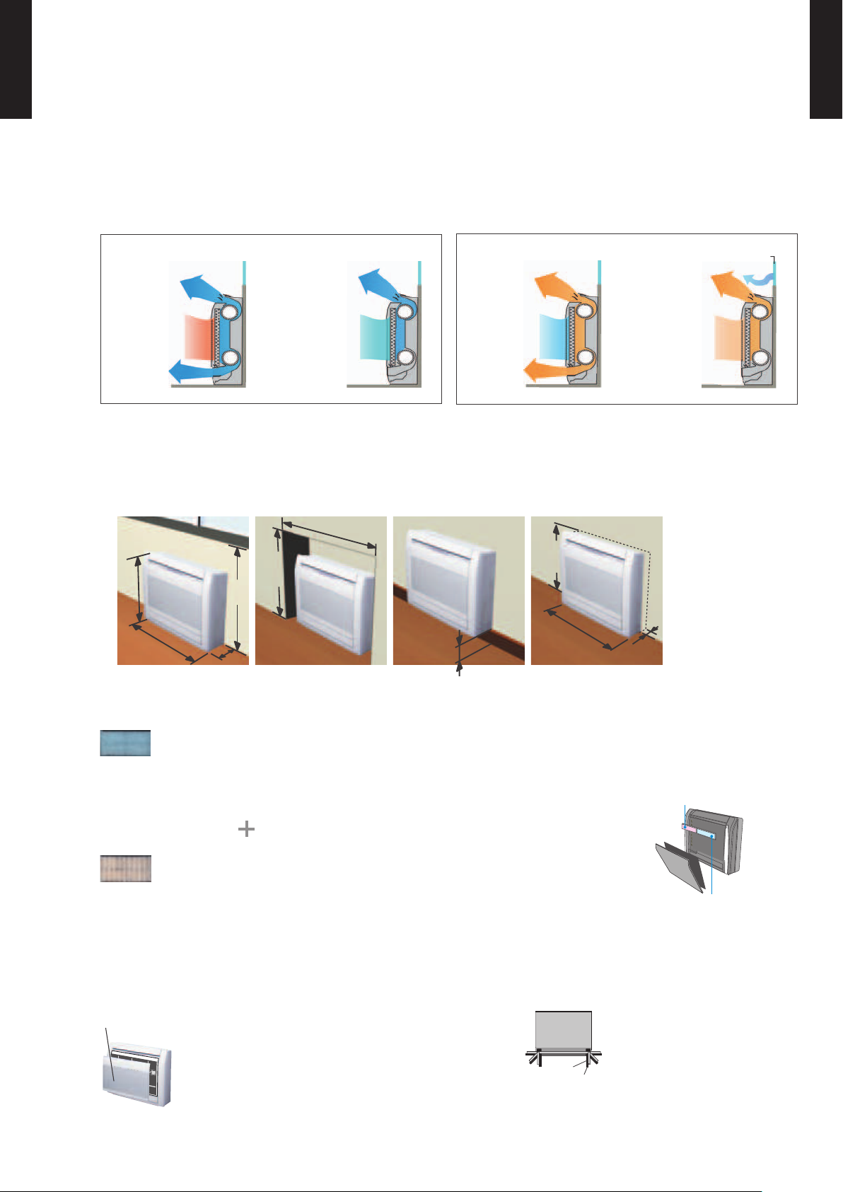
MULTI TYPE
Cooling
at operation
start
Prevents cold air
from falling
at stable
operation
at operation
start
Heating WindowPrevents cold
draft from
window
at stable
operation
Beneath
standard window
Standard concave
portion
Wall
Half concealed
Min.
27-9/16
(700)
Min.
23-1/4
(590)
Max.
3-1/8
(80)
Min.
28-3/4
(730)
Min.37 (940)
Max.
5-7/8
(150)
23-5/8
(600)
29-1/8
(740)
7-7/8
(200)
27-9/16
(700)
Remo
v
a
ble pane
l
Back view
Drain hose
Piping
1
6
2
5
3
4
Apple-catechin
Filter
Ion Deodorization
Filter
2, 3 ROOMS TYPE
MODELS : AGU9RLF, AGU12RLF, AGU15RLF
FEATURES
FLOOR TYPE 1-1-4.
2-Fan & Wide airow
z
Flexible & easy installation
z
Unit: in. (mm)
MULTI TYPE
2, 3 ROOMS TYPE
Filter features
z
ion deodorization lter
The lter deodorizes by powerfully decomposing absorbed odors using the oxidizing and reducing
effects of ions generated by the ultra-ne-particle ceramic.
Using different lters at both sides
Apple-catechin lter
Apple-catechin lter uses static electricity to clean ne particles and dust in
the air.
Easy maintenance
z
Removable and washable panel
Flexible piping connection
z
6 direction of drain & piping
- (01 - 05) -
Page 10

OUTDOOR UNIT1-2.
Heating capacity
Rated capacity
47°F
(8°C)
5°F
(-15°C)
-15°F
(-26°C)
100%
80%
60%
-4°F
(-20°C)
Workable down to -15°F(-26°C) outdoor temperature &
Powerful operation even at low outdoor temperature
Outdoor unit has a built- in heater to keep it from freezing during the freezing cold mid-winter season.
The air conditioner uses highly cold resistant components that were desinge d to prevent freezing
and meet CSA standards to provide comfortable herating even whrn temperature fall to -15°F(-26°C).
Equipped with a base heater that prevents
condensate from freezing.
Cultivated base design discharges melted
water through many holes.
Without a heater, freezing condensate can
cause noise, damage to blade, condense r,
and system performance.
Powerful heating at low
ambient te mperature.
Base Pan Heater
Base heater
Without
base heater
With
base heater
MULTI TYPE
2, 3 ROOMS TYPE
MULTI TYPE
2, 3 ROOMS TYPE
- (01 - 06) -
Page 11
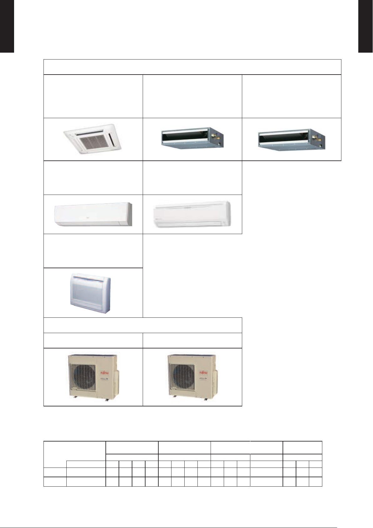
LINE UP1-3.
MULTI TYPE
2, 3 ROOMS TYPE
MODEL
INDOOR UNIT
MULTI TYPE
2, 3 ROOMS TYPE
AUU7RLF
AUU9RLF
AUU12RLF
AUU18RLF
ASU7RLF1
ASU9RLF1
ASU12RLF1
AGU9RLF
AGU12RLF
AGU15RLF
ARU7RLF
ARU9RLF
ARU12RLF
ASU18RLF
ARU18RLF
OUTDOOR UNIT
AOU18RLXFZH AOU24RLXFZH
Indoor units that can be connected to each outdoor unit
z
: Connectable / -: Not connectable
●
OUTDOOR
Btu Class 7 9 12 18 7 9 12 18 7 9 12 18 9 12 15
2 Rooms AOU18RLXFZH
3 Rooms AOU24RLXFZH
COMPACT
CASSETTE
AUU7-18RLF ARU7-18RLF ASU7-12RLF1 ASU18RLF AGU9-15RLF
● ● ● - ● ● ● - ● ● ● - ● ● -
● ● ● ● ● ● ● ● ● ● ● ● ● ● ●
SLIM DUCT WALL MOUNTED FLOOR
- (01 - 07) -
Page 12
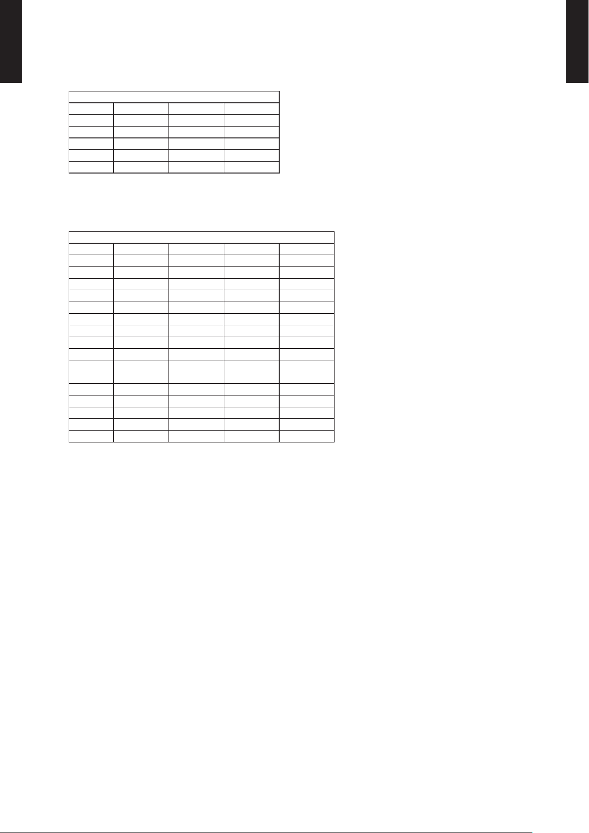
INDOOR UNIT CONNECTION PATTERNS
2 Rooms
MULTI TYPE
2, 3 ROOMS TYPE
z
AOU18RLXFZH
No. room 1 room 2 total
1 7 7 14
2 7 9 16
3 7 12 19
4 9 9 18
5 9 12 21
Notes) 7: 7,000Btu/h, 9: 9,000Btu/h, 12: 12,000Btu/h models
3 Rooms
z
AOU24RLXFZH
No. room 1 room 2 room 3 total
1 7 7 - 14
2 7 9 - 16
3 7 12 - 19
4 7 15 - 22
5 7 18 - 25
6 9 9 - 18
7 9 12 - 21
8 9 15 - 24
9 9 18 - 27
10 12 12 - 24
11 12 15 - 27
12 7 7 7 21
13 7 7 9 23
14 7 7 12 26
15 7 9 9 25
16 9 9 9 27
MULTI TYPE
2, 3 ROOMS TYPE
Notes) 7: 7,000Btu/h, 9: 9,000Btu/h, 12: 12,000Btu/h, 15: 14,000Btu/h, 18: 18,000Btu/h models
- (01 - 08) -
Page 13
REMOTE CONTROLLER2.
60min.
2°F (1°C)
4°F (2°C)
Timer setting
2°F (1°C)
4°F (2°C)
6°F (3°C)
8°F (4°C)
30min.
60min.
90min.
Timer setting
A B C D
A B
C
D
Mixed-up
I.U. I.U. I.U. I.U.
I.U. I.U. I.U. I.U.
After code change
WIRELESS REMOTE CONTROLLER2-1.
MULTI TYPE
2, 3 ROOMS TYPE
MODEL: UTY-LNHUM
FEATURES
4 mode timer setup available (ON / OFF / PROGRAM /SLEEP). ●
Can be used jointly with wired remote controllers . ●
Easy to change custom code (max. 4 custom codes) by button operation. ●
Built-in timers
z
Select from four different timer programs (ON/OFF/PROGRAM/SLEEP).
Program timer
z
The program timer operates the ON and OFF timer once within a 24 hour period.
MULTI TYPE
2, 3 ROOMS TYPE
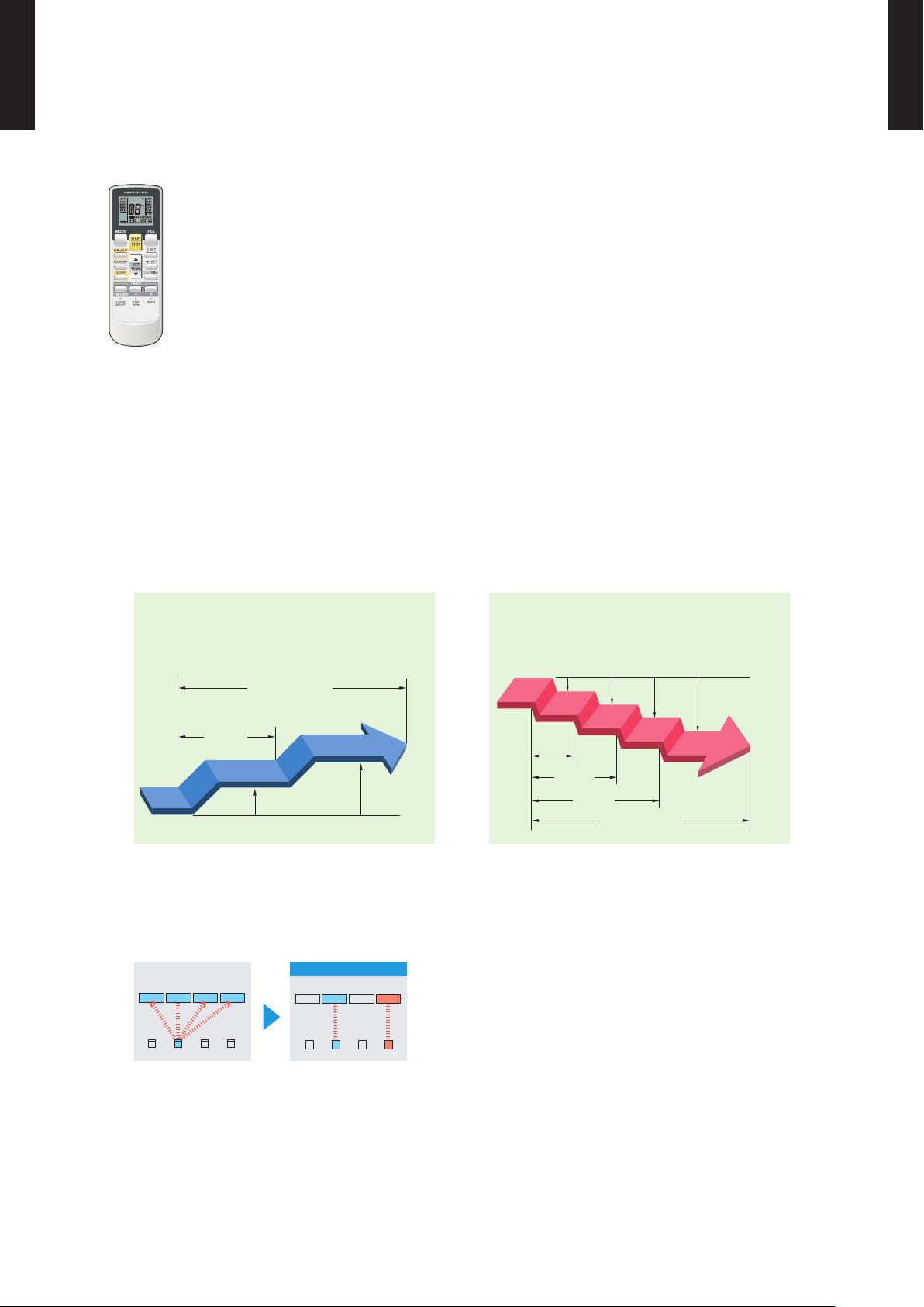
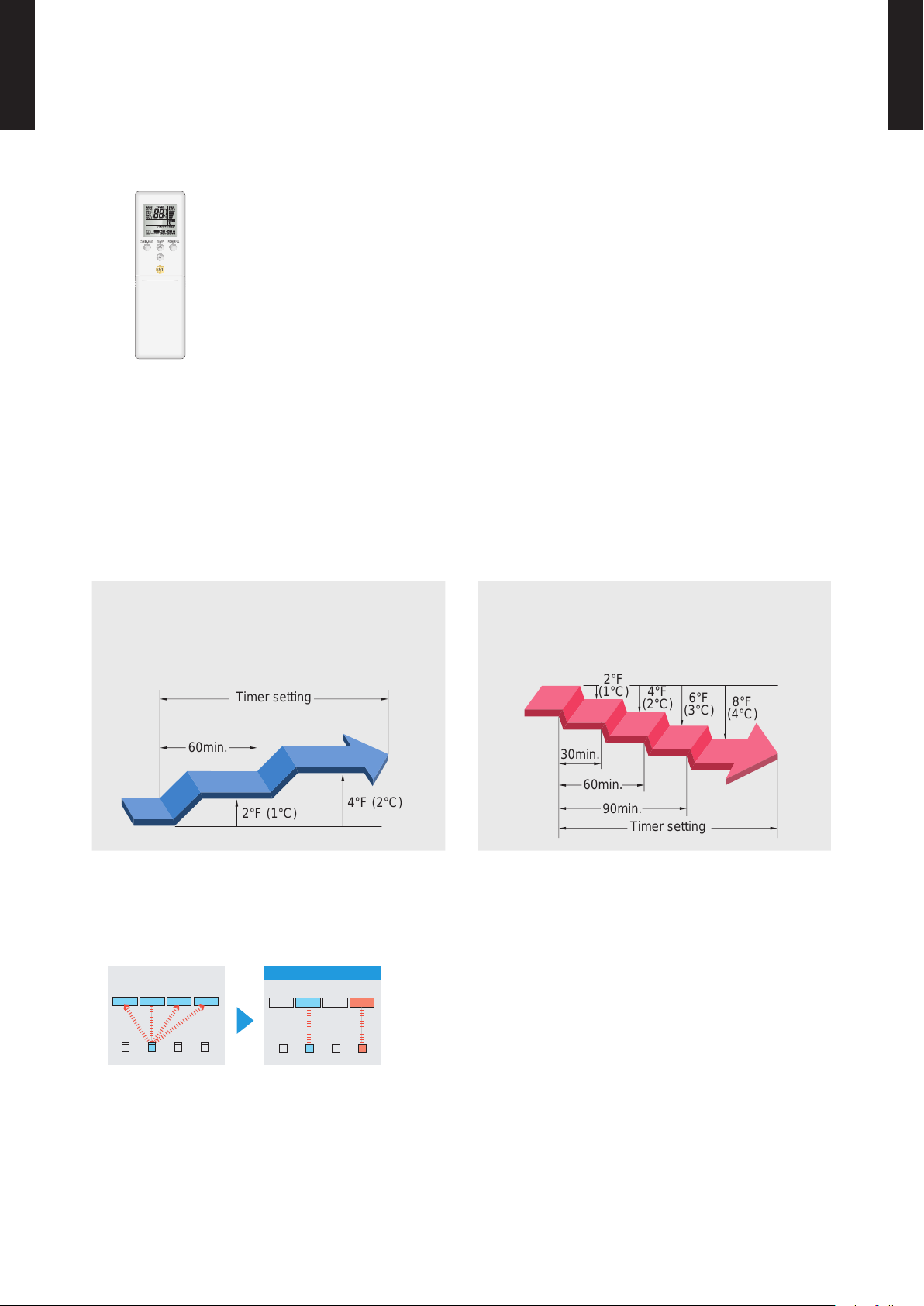
Sleep timer
z
The sleep timer function automatically corrects the temperature thermostat setting according to the
time setting to prevent excessive cooling and heating while sleeping.
Cooling operation / dry operation
When the sleep timer is set, the set temperature
automatically rises 2°F (1°C) every hour. The set
temperature can rise up to a maximum of 4°F (2°C).
Simple function setting
z
Heating operation
When the sleep timer is set, the set temperature
automatically drops 2°F (1°C) every 30 minutes. The
set temperature can drop to a maximum of 8°F (4°C).
Setting of the air conditioner selection function is performed by remote controller.
Switching remote controller custom code
z
Code selector switch eliminates unit
•
being wrongly switched.
(Up to 4 custom codes can be set.)
*I.U.=Indoor unit
- (01 - 09) -
Page 14
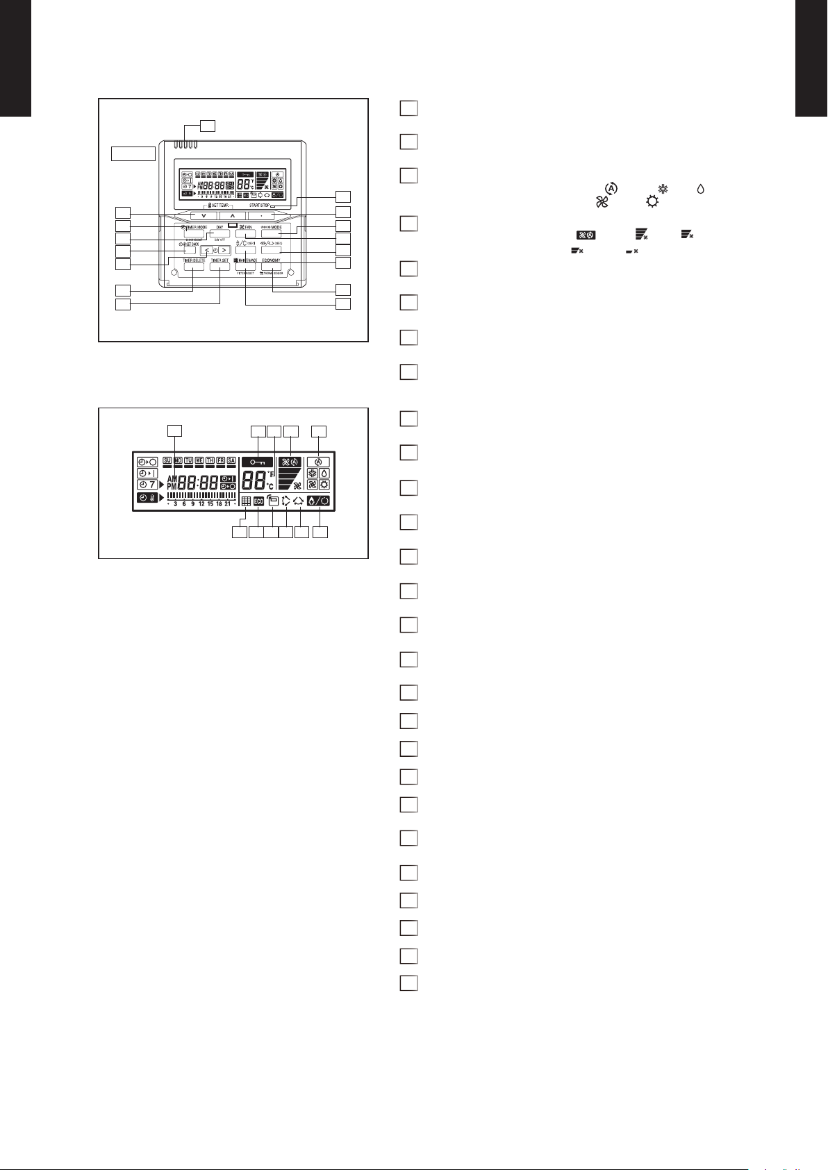
FUNCTIONS (UTY-LNHUM)
2
4
9
3
1
16
15
5
10
13
11
12
14
8
7
6
17
18
19
21
24
23
22
20
MULTI TYPE
2, 3 ROOMS TYPE
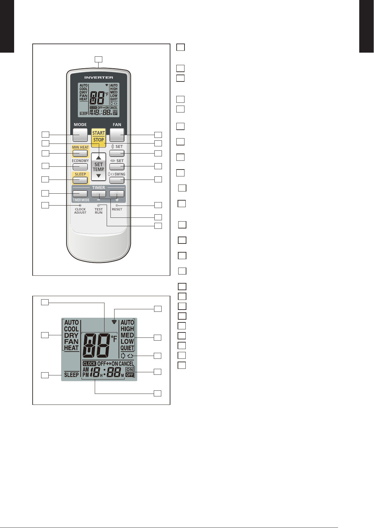
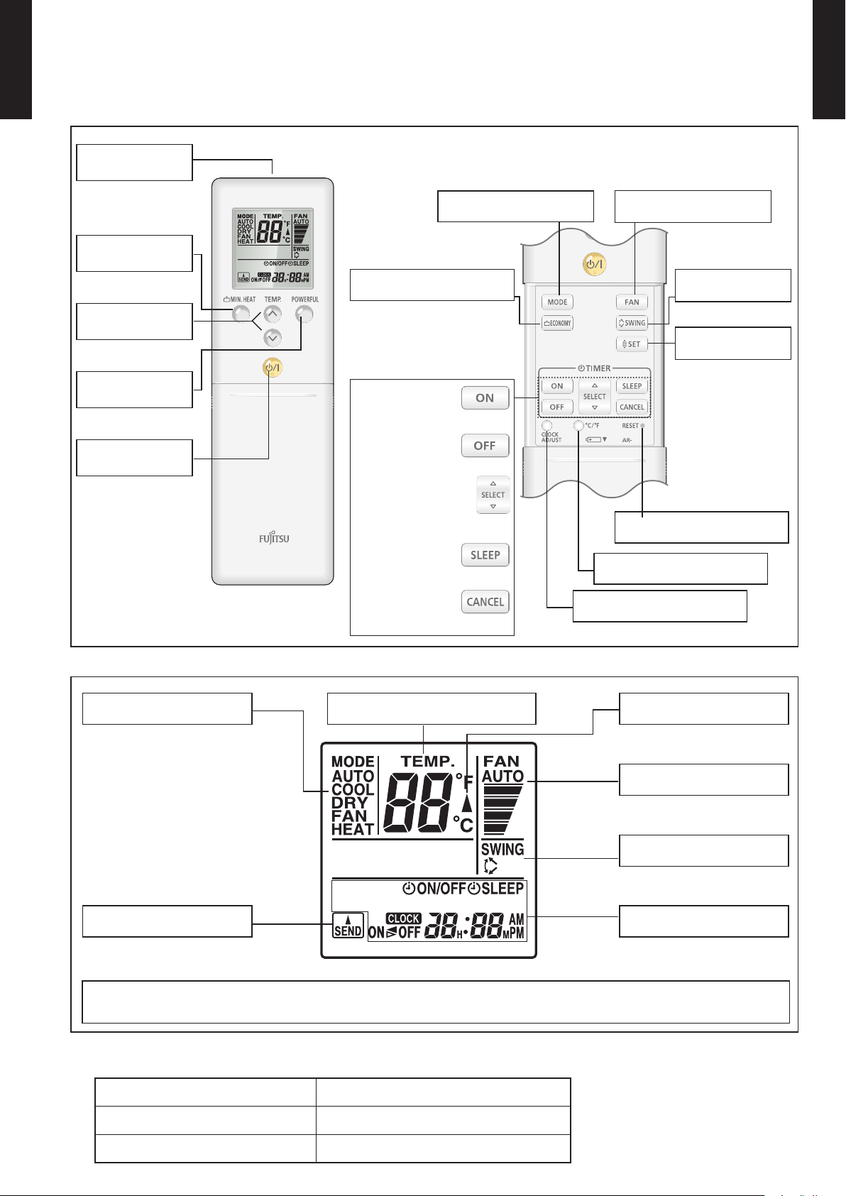
MODE button1
Selects the operating mode (AUTO, COOL, DRY, FAN, HEAT).
/Start / end R.C. custom code change. (Max 4 codes)
MULTI TYPE
2, 3 ROOMS TYPE
MIN.HEAT button2
SET TEMP. button ( ▲ / ▼ )3
Sets the indoor temp./ Sets R.C. custom code.
ECONOMY button4
SLEEP button5
Pressed to select sleep timer.
FAN button6
Selects the fan speed (AUTO, HIGH, MED, LOW, QUIET).
START/STOP button7
Pressed to start and stop operation.
SET button (Vertical)8
Air ow direction vertical set button.
SET button (Horizontal)9
Air ow direction horizontal set button.
SWING button10
Air ow direction swing button.
TIMER MODE button11
Pressed to select the timer mode. (OFF TIMER, ON TIMER,
PROGRAM TIMER, TIMER RESET)
TIMER set ( + / - ) button12
Sets the current time and on-off time.
CLOCK ADJUST button13
Sets the current time.
RESET button14
Used when replacing batteries.
TEST RUN button15
Used when testing the air conditioner after installation.
Display panel
Signal transmitter16
Temperature set indicator17
Operating mode indicator18
Sleep indicator19
Transmit indicator20
Fan speed indicator21
Swing indicator22
Timer mode indicator23
Clock indicator24
Note: Functions will be different due to type of indoor unit.
For details, please see operation manual.
- (01 - 10) -
Page 15
SYSTEM DIAGRAM
6-11/16 (170)
2-3/16 (56)
3/4 (19)
2-3/8 (60.4)
1-3/16 (30.2)
Ø1/8 (3.5)
1/8 x 1/4 (3.5 x 6.5)
(HOLE)
(HOLE)
1-1/16 (26.2)
1 (25.5)
3-3/4 (95)
6-1/16 (154.7)
MULTI TYPE
2, 3 ROOMS TYPE
MULTI TYPE
2, 3 ROOMS TYPE
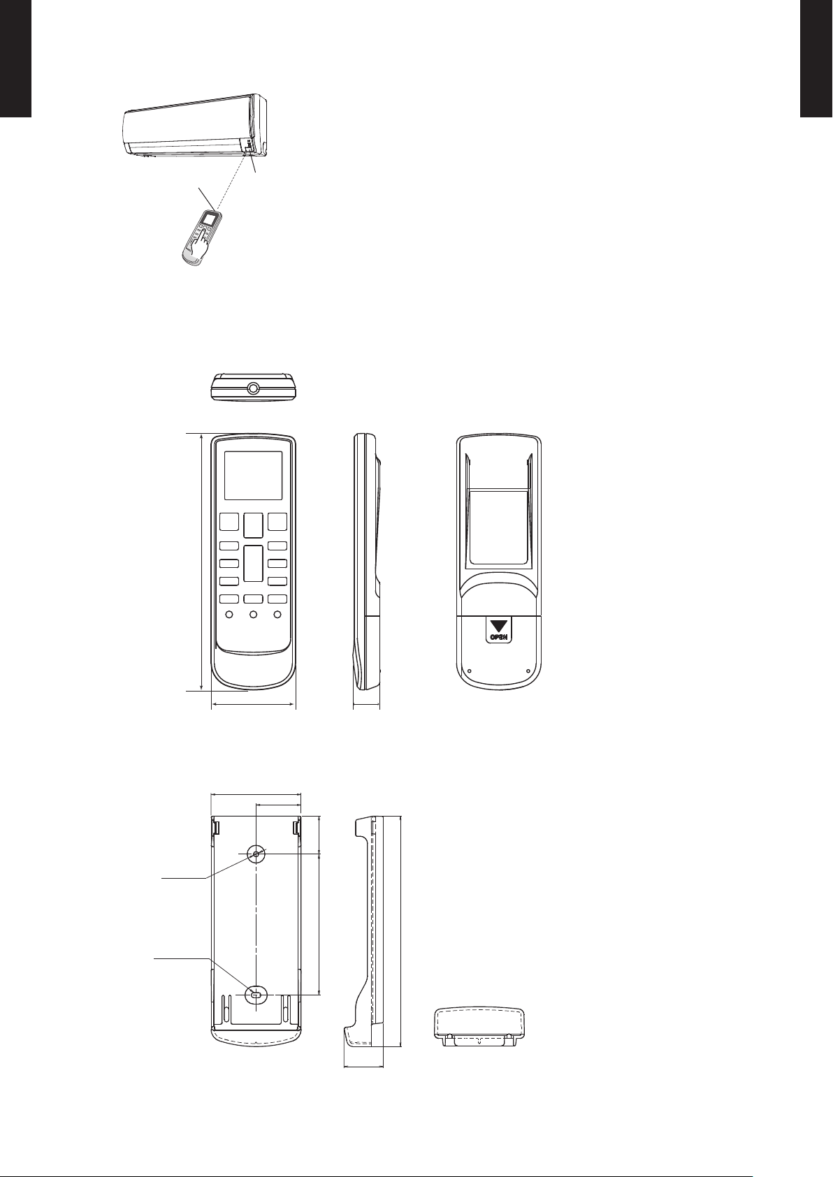
Control signal might not be recognized in following cases: ●
(i) A curtain or a wall, etc. exists between transmitter and receiver.
(ii) There is an instant-start type (inverter type, etc.) uorescent lamp
Signal transmitter
Signal receiver
window
in the room.
Air conditioner might not work correctly when strong light hits the ●
signal receiver window. Shut off the direct sunlight and also make
illuminator far away from the receiver window.
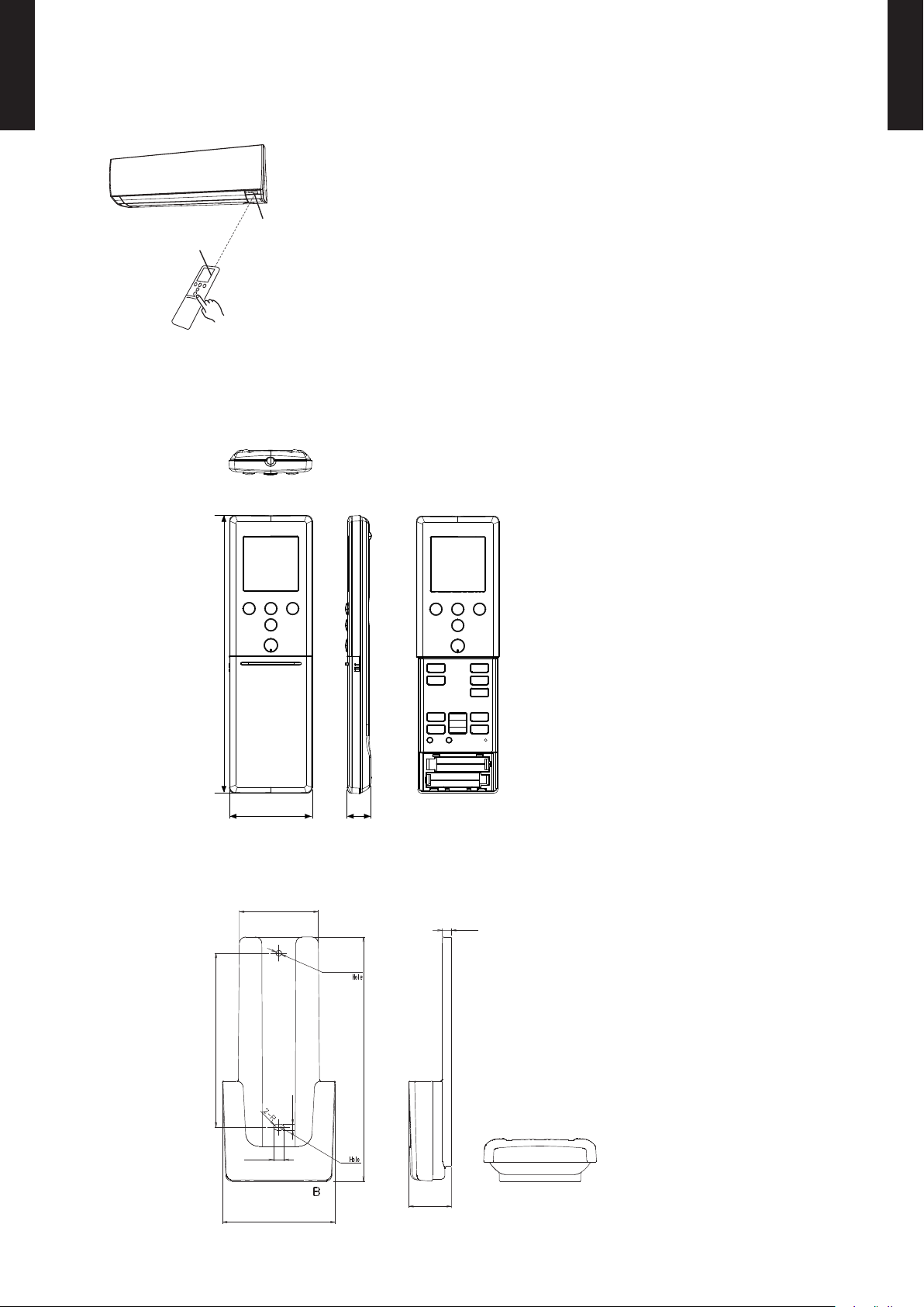
DIMENSIONS
Controller
z
Unit : in. (mm)
Top View
Holder
z
Front View Rear View
Side View
Front View Side View Bottom View
- (01 - 11) -
Page 16
MULTI TYPE
2, 3 ROOMS TYPE
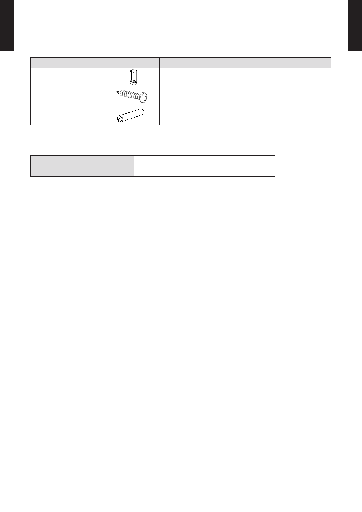
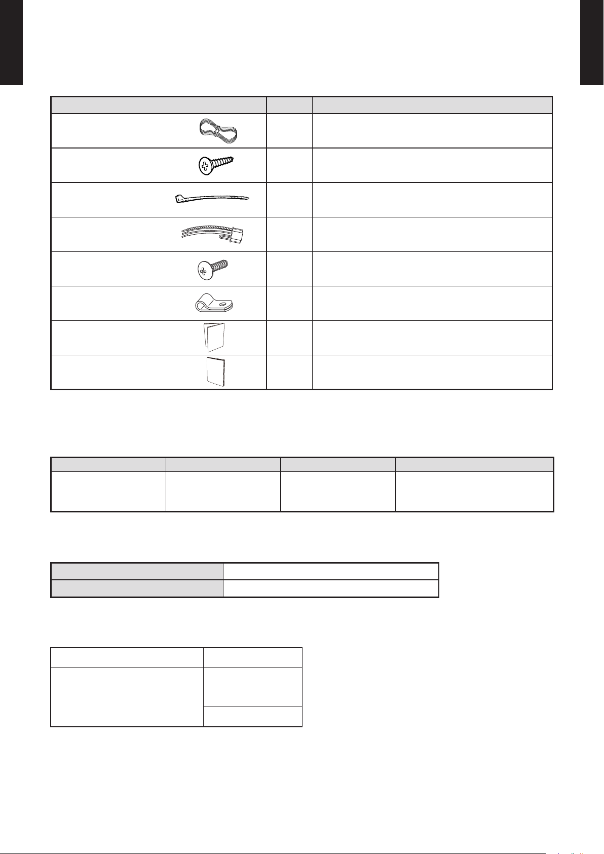
PACKING LIST
Name and shape Quantity Application
MULTI TYPE
2, 3 ROOMS TYPE
Remote controller holder 1
Tapping screw 2
Battery
[ 1.5V (R03 / AAA) ]
SPECIFIC ATIONS
Dimensions [H x W x D]: in. (mm) 6-11/16 (170) x 2-3/16 (56) x 3/4 (19)
Weight : oz. (g) 3 (85) [w/o batteries]
2 For remote controller
Use as remote controller holder
For remote controller holder installation
- (01 - 12) -
Page 17
MULTI TYPE
60min.
2°F (1°C)
4°F (2°C)
Timer setting
30min.
60min.
90min.
8°F
(4°C)
Timer setting
6°F
(3°C)
4°F
(2°C)
2°F
(1°C)
A B C D
A B
C
D
Mixed-up
I.U. I.U. I.U. I.U.
I.U. I.U. I.U. I.U.
After code change
REG1U
2, 3 ROOMS TYPE
MODEL: AR-REG1U
MULTI TYPE
2, 3 ROOMS TYPE
FEATURES
Built-in timers
z
4 mode timer setup available (ON / OFF / PROGRAM / SLEEP).
Easy operation.
Easy to change custom code (max. 4 custom codes) by button operation.
Select from four different timer programs (On / Off / Program / Sleep).
Program timer
z
The program timer operates the on and off timer once within a 24-hour period.
Sleep timer
z
The sleep timer function automatically corrects the temperature thermostat setting according to
the timer setting to prevent excessive cooling and heating while sleeping.
Cooling operation/dry operation
When the sleep timer is set, the set temperature
automatically rises 2°F (1°C) every hour. The set
temperature can rise up to a maximum of 4°F (2°C).
Heating operation
When the sleep timer is set, the set temperature
automatically drops 2°F (1°C) every 30 minutes. The
set temperature can drop to a maximum of 8°F (4°C).
Simple function setting
z
Setting of the air conditioner selection function is performed by remote controller.
Switching remote controller custom code
z
Code selector switch eliminates unit
•
being wrongly switched.
(Up to 4 custom codes can be set.)
*I.U.=Indoor unit
To change the temperature unit
z
Easy to change the temperature unit (
°F ↔ °C) by button operation.
- (01 - 13) -
Page 18
MULTI TYPE
REG1U
REG1U
2, 3 ROOMS TYPE
FUNCTIONS (AR-REG1U)
MULTI TYPE
2, 3 ROOMS TYPE
Signal
transmitter
MIN. HEAT
button
TEMP.
button
POWERFUL
button
Start/Stop
button
ECONOMY button
TIMER ON button
TIMER OFF button
TIMER SELECT button
TIMER SLEEP button
TIMER CANCEL button
MODE button
CLOCK ADJUST button
FAN button
SWING button
SET button
RESET button
°C / °F switching button
Display panel
Mode indicator
Temperature indicator
Send indicator
To facilitate explanation, the accompanying illustration has been drawn to show all possible indicators; in actual operation,
however, the display will only show those indicators appropriate to the current operation.
SPECIFIC ATION
Transmit indicator
Fan Speed indicator
Swing indicator
Clock & Timer
indicator
DIMENSIONS [H × W × D]: in. (mm) 8-1/16 (205) × 2-3/8 (61) × 11/16 (17)
WEIGHT oz. (g) 4.3 (122)
ACCESSORY Holder
- (01 - 14) -
NOTE: Some button operations may
not be available for all units
or systems.
For details, refer to the
operation manual.
Page 19
MULTI TYPE
8-1/16 (205)
11/16
(17)
2-3/8
(61)
Ø1/8 (Ø3.5)
1-15/16 (48.5)
4-3/16 (106.8)
5-7/8 (150)
1/8 (3.5)
1/4 (6.5)
2-3/4 (69.3)
1-1/16 (26.2)
3/16 (5.5)
2, 3 ROOMS TYPE
SYSTEM DIAGRAM
MULTI TYPE
2, 3 ROOMS TYPE
Control signal might not be recognized in following cases: ●
(i) A curtain or a wall, etc. exists between transmitter and receiver.
Signal transmitter
Signal receiver
window
(ii) There is an instant-start type (inverter type, etc.) uorescent lamp
in the room.
Air conditioner might not work correctly when strong light hits the ●
signal receiver window. Shut off the direct sunlight and also make
illuminator far away from the receiver window.
DIMENSIONS
Controller
z
[Unit: in.(mm)]
Top View
Holder
z
Front View Front View
Side View
Front View Side View Bottom View
- (01 - 15) -
Page 20

MULTI TYPE
2, 3 ROOMS TYPE
PACKING LIST
Name and shape Quantity Application
MULTI TYPE
2, 3 ROOMS TYPE
Remote controller holder 1
Tapping screw 2
Battery
[ 1.5V (LR03 / AAA) ]
SPECIFIC ATIONS
Dimensions [H x W x D]: in.(mm) 8-1/16 (205) × 2-3/8 (61) × 11/16 (17)
Weight: oz.(g) 4.3 (122) [w/o batteries]
2 For remote controller
Use as remote controller holder
For remote controller holder installation
- (01 - 16) -
Page 21
WIRED REMOTE CONTROLLER 2-2.
76°F (24°C)
0 3 6 9 12 15 18 21
O'clock
12 3 6 9 12 3 6 9
time
AM PM
84°F (28°C)
0 3 6 9 12 15 18 21
O'clock
12 3 6 9 12 3 6 9
time
AM PM
76°F 84°F 76°F
0 3 6 9 12 15 18 21
O'clock
12 3 6 9 12 3 6 9
time
AM PM
76°F (24°C)
84°F (28°C)
24°C 28°C 24°C
MULTI TYPE
2, 3 ROOMS TYPE
(For Compact cassette type, Slim duct type)
MULTI TYPE
2, 3 ROOMS TYPE
FEATURES
Various timer setup (ON/OFF/WEEKLY) are possible. ●
Equipped with weekly timer as standard function. ●
(Start/Stop function is twice per day for a week)
When setting up a timer, start/stop and a temperature setup can ●
be changed.
When a failure occurs,the error code is displayed. ●
Error history.(Last 16 error codes can be accessed.) ●
The room temperature can be controlled by being detective the ●
temperature accurately with Built-in thermo sensor.
Powerful features and compact size
z
Individual
control
Accurate and comfortable
z
Indoor temperature can be detected accurately by the inclusion of a
thermo sensor in the body of the wired controller.
Our system can correspond to various scenes.
This wired remote controller and the optional remote sensor allows
exibility in sensor location, and suitable for all requirements.
Thermo
sensor
Weekly
timer
Setback
timer
Wired
remote
controller
Sensor part
Thermo sensor
indicator
Control part for
changing the
thermo sensor
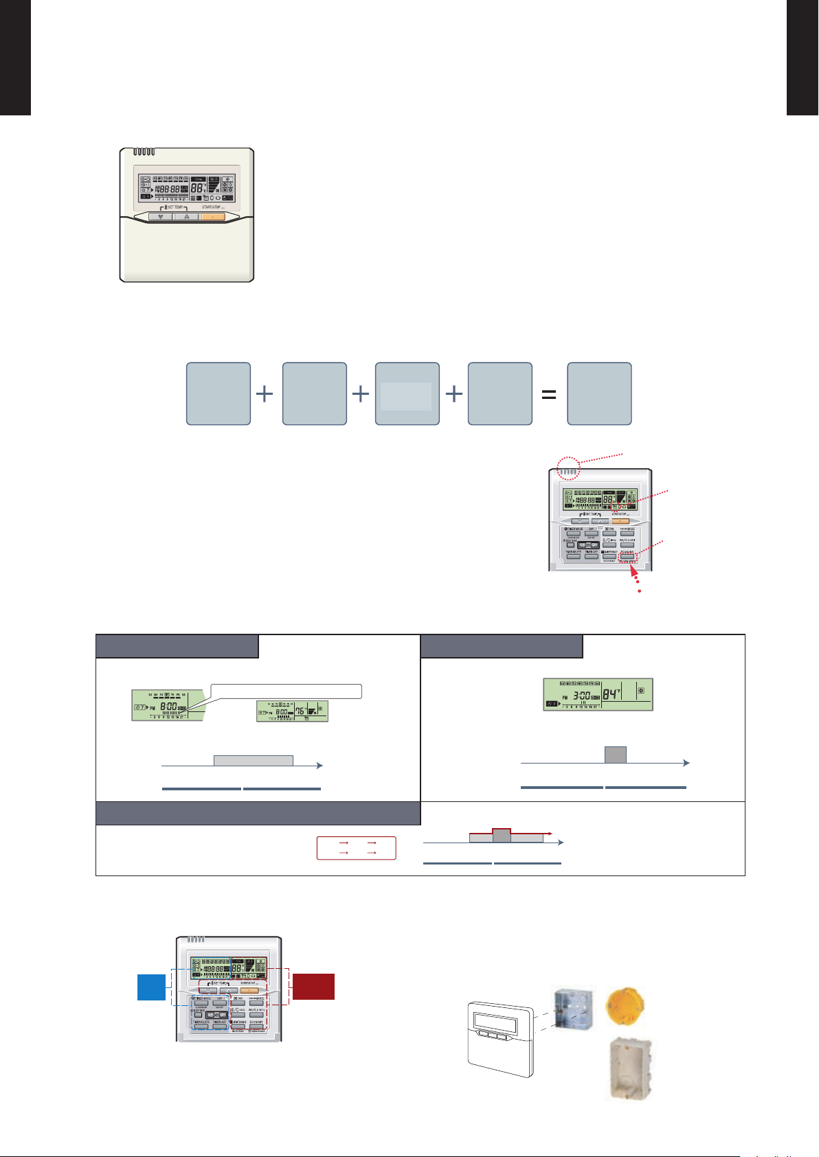
Built-in timers
z
Weekly timer Setback timer
Possible to set ON/OFF time to operate twice each day of the
week.
Example : setup sc reen
(Set to Wedne sday: 8:0 0 to 20:00.)
Easy-to-understa nd time ba r display
Screen
after setup
Possible to set temperature for two time spans and for each
day of the week.
At "Weekly timer" + "Set back timer" setup
Easy-to-understand operation
z
Timer
area
Operation
area
Simple installation
z
Components are compatible with standard switch
boxes. Flat back surface allows equipment to be
installed wherever it is needed.
Example : setup sc reen
(Set from S unday to Sat urday: 12:0 0 to 15:00, 28 °C .)
[Variable timer control]
The operation/display sections are zoned according
to time and operation, enabling variable programming
to match application.
- (01 - 17) -
European
switch b ox
JIS box
Page 22
FUNCTIONS
7
Display
13
12
11
10
2
8
9
16
15
14
1
3
5
4
6
18
17
1920 21
2223 242527 26
MULTI TYPE
2, 3 ROOMS TYPE
START/STOP button1
Pressed to start and stop operation.
MULTI TYPE
2, 3 ROOMS TYPE
SET TEMP. button2
Selects the setting temperature.
MODE button3
Selects the operating mode ( AUTO , COOL , DRY
FAN , HEAT ).
,
FAN button4
Selects the fan speed ( AUTO , HIGH
LOW , QUIET ).
,
MED ,
Vertical air ow direction and swing button5
Press for two seconds to change the swing mode
Horizontal air ow direction and swing button6
Press for two seconds to change the swing mode.
Built-in thermo sensor7
Detect room temperature.
TIMER MODE (CLOCK ADJUST) button8
Display panel
Selects the timer mode (OFF TIMER, ON TIMER, WEEKLY TIMER)
Set the current time.
DAY (DAY OFF) button9
Temporarily cancels of one day timer.
SET BACK button10
Pressed select the set back timer.
SET TIME button11
Pressed to select the set back timer.
TIMER DELETE button12
The schedule of a weekly timer is deleted.
TIME SET button13
Sets the date, hour, minute and on-off time.
ECONOMY (THERMO SENSOR) button14
FILTER RESET button15
Operation lamp16
Lights during operation and when the timer is on.
Timer and clock indicator17
Operation mode indicator18
Fan speed indicator19
Operation lock indicator20
Temperature indicator21
Displayed temperature is set temperature.
Defrost indicator22
Indicates during the oil recovery and defrosting operation.
Vertical swing indicator 23
Horizontal swing indicator 24
Economy indicator25
Thermo sensor indicator 26
Filter indicator27
Note: Functions will be different due to type of indoor unit.
For details, please see operation manual.
- (01 - 18) -
Page 23
MULTI TYPE
Primary
Secondary
A B C
Indoor unit
REMOTE
CONTROLLER
1 2 3
1 2 3
Primary
Secondary
Indoor unit
1 2 3
1 2 3 1 2 3
REMOTE
CONTROLLER
3-5/16 (83.5)
5/8 (15.3)
2-1/2 (63.5)
Hole
1-13/16 (45.3)
3/16 (4.5)3/16 (4.5)
3/16 (4.5)
3/8 (9)
1/2 (12.5)
Hole x 2
Hole x 3
1/4 (6)
1-3/16 (30) 1-5/16 (33.5)
7/8 (23)
4- 3/4 (120)
4- 3/4 (120)
4- 3/4 (120)
11/16 (18)
2, 3 ROOMS TYPE
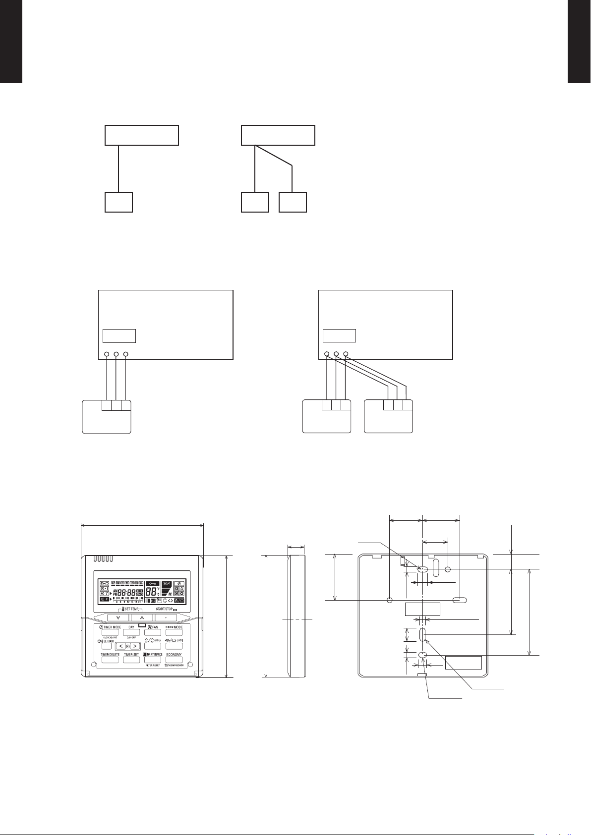
SYSTEM DIAGRAM
MULTI TYPE
2, 3 ROOMS TYPE
1 remote controller
z
Indoor unit Indoor unit
Remote controller Remote controllers
ELECTRICAL WIRING
1 remote controller
z
z
2 remote controllers
A , B , C : Remote controller cable.
A
z
2 remote controllers
<
1,640ft (500m) ; B+C
=
<
1,640ft (500m)
=
Remote controller Remote controllers
DIMENSIONS
Front View Side View Rear View
1 (RED) : 12V
2 (WHITE) : Signal
3 (BLACK) : COM
Unit : in. (mm)
- (01 - 19) -
Page 24
INSTALLATION
PCB
13/16 in.
(20 mm)
Connection Pattern
MULTI TYPE
2, 3 ROOMS TYPE
z
MULTI TYPE
2, 3 ROOMS TYPE
Note: Connection pattern is different according to type of Indoor unit.
Indoor unit types Connection Pattern
Wall Mounted type
Pattern A
z
Compact Cassette type
Slim Duct type
ASU7RLF1, ASU9RLF1, ASU12RLF1 Pattern B
ASU18RLF
Floor type
Pattern A
Pattern C
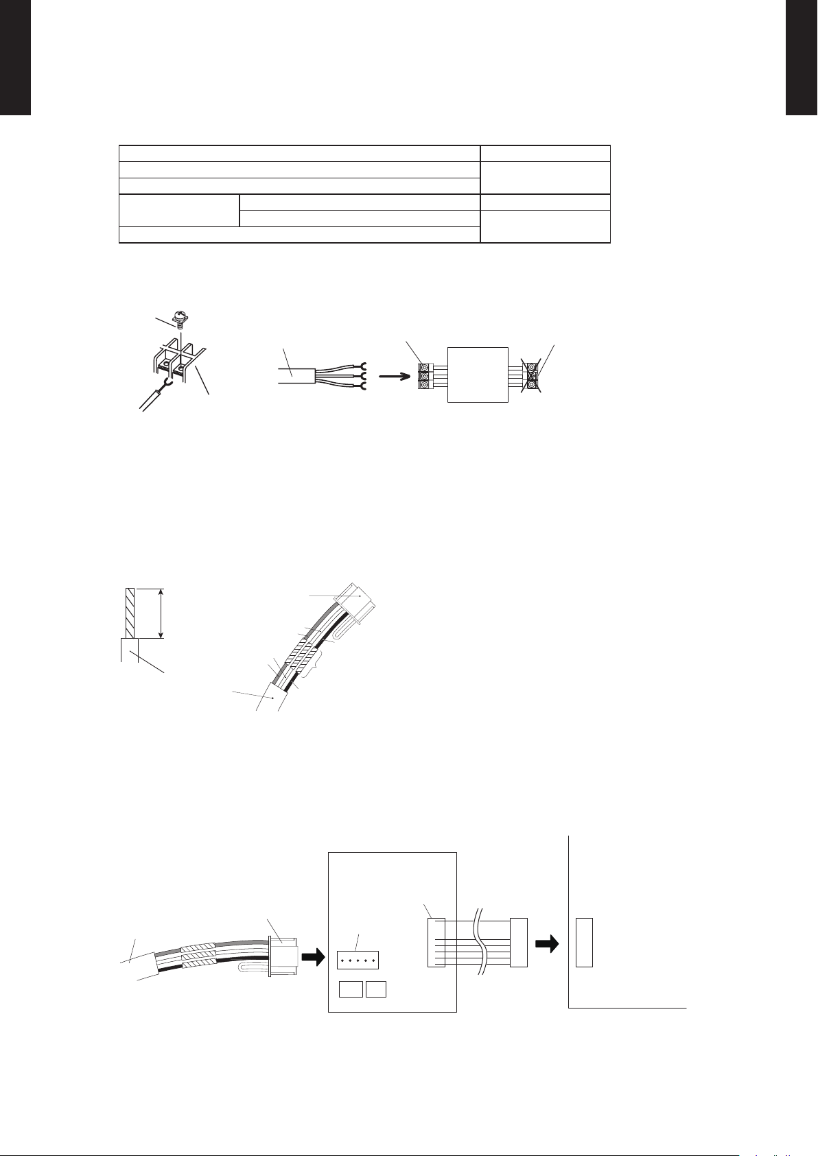
Connect the end of remote controller cable directly to the exclusive terminal block.
M4 screw
Terminal block
Remote
controller
cable
Remote controller
terminal block
Indoor unit
Outdoor unit /
Power supply
terminal block
Note: It may be failed if it is connected to the outdoor unit or the terminal block for power supply.
Pattern B
z
1) Modify the remote controller cable as per below methods.
Use a tool to cut off the terminal on the end of the remote controller cable and then remove ●
the insulation from the cut end of the cable as shown in Fig.
Connect the remote controller cable and connecting cable as shown in Fig. ●
Be sure to insulate the connection between the cables. ●
Connecting
cable
White
Remote controller
cable
Red
White
Red
Black
Black
Insulated
connection
2) Method of connecting remote controller cable
Connecting cable made by above-mentioned 1) is connected with terminal (*1) of optional ●
communication kit.
Cable connected with terminal (*2) of communication kit is connected with PCB of Indoor unit. ●
*1: CNC01 (for ASU7RLF1, ASU9RLF1, ASU12RLF1: UTY-XCBXZ2)
*2: CND01 (for ASU7RLF1, ASU9RLF1, ASU12RLF1: UTY-XCBXZ2)
Terminal
(*2)
Remote controller
cable
Connecting
cable
Terminal
(*1)
Communication kit Indoor unit PCB
- (01 - 20) -
Page 25
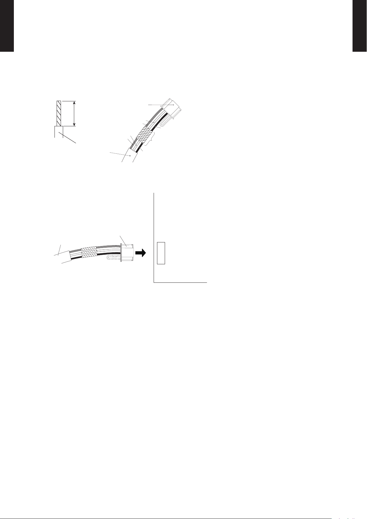
Pattern C
13/16 in.
(20 mm)
MULTI TYPE
2, 3 ROOMS TYPE
z
MULTI TYPE
2, 3 ROOMS TYPE
1) Modify the remote controller cable as per below methods.
Use a tool to cut off the terminal on the end of the remote controller cable and then remove ●
the insulation from the cut end of the cable as shown in Fig.
Connect the remote controller cable and connecting cable as shown in Fig. ●
Be sure to insulate the connection between the cables. ●
Connecting
cable
White
Red
Black
Insulated
connection
Remote controller
cable
White
Red
Black
2) Method of connecting remote controller cable
Connecting cable made by above-mentioned 1) is connected with PCB of Indoor unit. ●
Remote controller
cable
Connecting
cable
Indoor unit PCB
- (01 - 21) -
Page 26
MULTI TYPE
2, 3 ROOMS TYPE
PACKING LIST
Name and shape Quantity Application
MULTI TYPE
2, 3 ROOMS TYPE
Remote controller cable
[33ft(10m)]
Screw
(M4 x 16mm)
Binder 1
Connecting cable
Screw *1
(M4 x 14mm)
Cable clamper *1
Installation manual
Operating manual
Use only if the remote controller cable must be modied for the indoor unit model.
*1:
*1 1
For connecting the remote controller
1
For installing the remote controller
2
For remote controller and remote controller cable
binding
For connecting the remote controller cable to the
Wall mounted type indoor unit
For installing the remote controller cable to the
1
indoor unit
For installing the remote controller cable to the
1
indoor unit
1
1
WIRING SPECIFICATIONS
Use Cable size Wire type Remarks
Remote controller
cable
SPECIFIC ATIONS
Dimensions [H x W x D]: in.(mm) 4-3/4 (120) x 4-3/4 (120) x 11/16 (18)
Weight: oz. (g) 5.6 (160)
PART (OPTIONAL)
Model name
22AWG
( 0.33 mm
Wall mounted type
ASU7RLF1
ASU9RLF1
ASU12RLF1
UT Y-XCBXZ2
2
)
Polar 3 core Use sheathed PVC cable
* The communication kit is needed for connecting the wired remote controller to the Wall mounted type.
- (01 - 22) -
Page 27
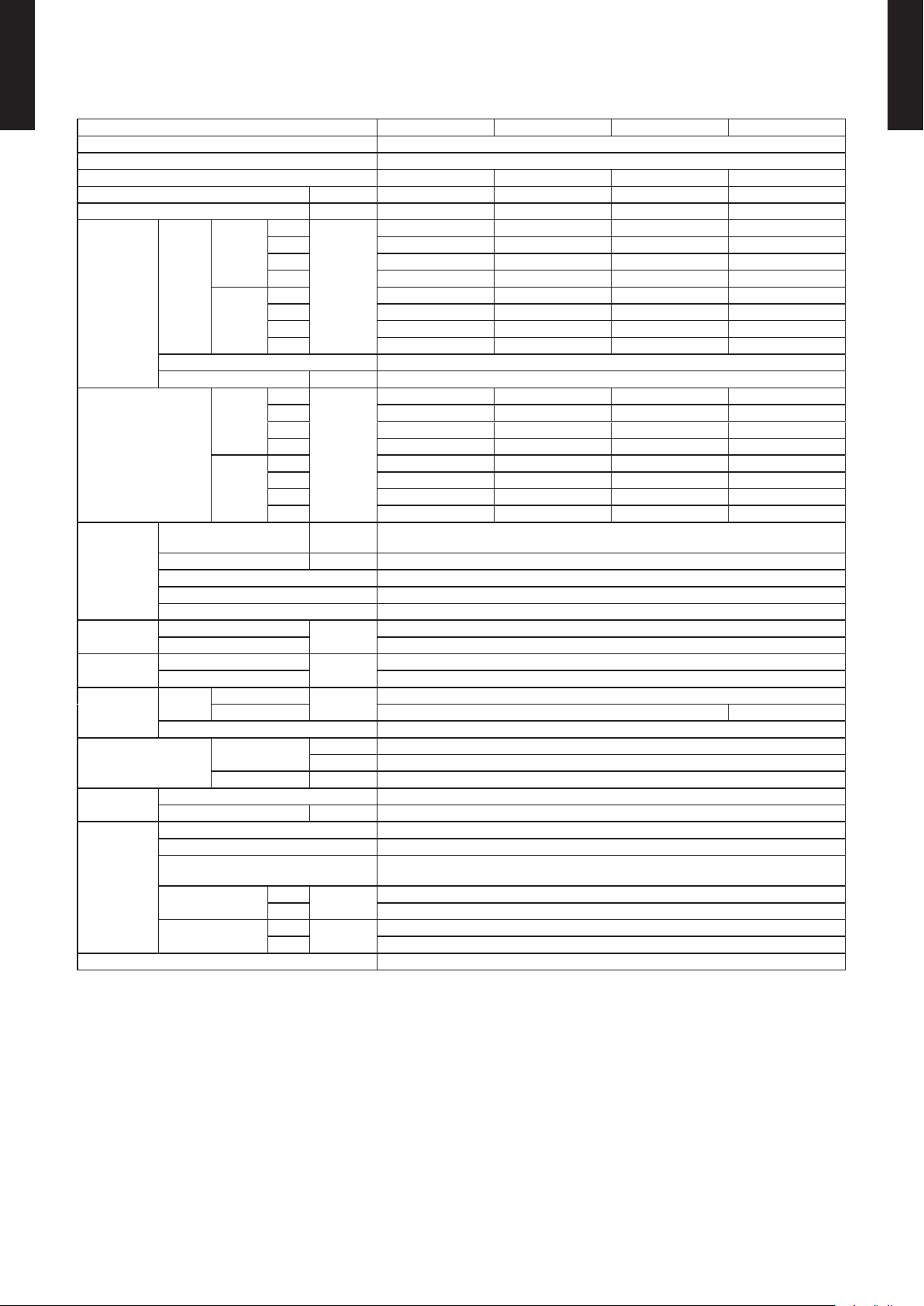
SPECIFICA TIONS3.
COMPACT CASSETTE TYPE3-1.
MULTI TYPE
2, 3 ROOMS TYPE
Model name AUU7RLF AUU9RLF AUU12RLF AUU18RLF
Power source 1ø 208/230V 60Hz
Available voltage range 187-26 4V
Capacity 7,000 Btu/h class 9,000 Btu/h class 12,000 Btu/h class 18,000 Btu/h class
Input power W 18 18 23 39
Running current A 0.15 0.15 0.19 0.30
High
Cooling
Airow
Fan
Sound pressure level *
Heat
exchanger
Dimensions
(H × W × D)
Weight
Connection
pipe
Operation range
Drain hose
Cassette
grille
Remote controller type Wired [Wireless(option)]
NOTE :
• The protective function might work when using it outside the operation range.
*: These are the measured values in the manufacturer’s anechoic chamber.
Because of the surrounding sound environment, the sound levels measured in actual installation conditions might be higher than the
specied values here.
rate
Heating
Fan Type × Q'ty Turbo × 1
Fan Motor Output W 54
Cooling
Heating
Dimension (H × W × D) in. (mm)
Fin pitch FPI 21
Rows × Stages 2 × 10
Pipe type Copper tube
Fin Type Aluminum
Net
Gross 10-7/16 × 28-3/4 × 24-5/8 (265 × 730 × 625)
Net
Gross 40 (18)
Size
Method Flare
Material HARD PVC
size in. [mm] Ø 1(I.D.), Ø 1-1/4(O.D.) [Ø 25 (I.D.), Ø 32 (O.D.)]
Model name UTG-CCGF
Material PS
Color
Dimensions
(H × W × D)
Weight
Liquid
Gas Ø3/8 (Ø9.52) Ø1/2 (Ø12.70)
Cooling
Heating °F (°C) 60 to 88 (16 to 31)
Med 288 (490) 288 (490) 312 (530) 359 (610)
Low 259 (440) 259 (440) 277 (470) 306 (520)
Quiet 230 (390) 230 (390) 241 (410) 241 (410)
High 318 (540) 318 (540) 359 (610) 471 (800)
Med 288 (490) 288 (490) 312 (530) 418 (710)
Low 259 (440) 259 (440) 277 (470) 353 (600)
Quiet 230 (390) 230 (390) 241 (410) 265 (450)
High
Med 31 31 33 37
Low 29 29 31 33
Quiet 27 27 28 29
High 34 34 37 44
Med 32 32 33 40
Low 29 29 31 37
Quiet 27 27 28 30
Net
Gross 4-3/4 × 30-1/8 × 29-3/4 (120 × 765 × 755)
Net
Gross 10 (4.5)
CFM
(m3/h)
dB (A)
in. (mm)
lbs. (kg)
in. (mm)
°F (°C) 64 to 90 (18 to 32)
%RH 80 or less
in. (mm)
lbs. (kg)
318 (540) 318 (540) 359 (610) 441 (750)
33 33 37 42
8-1/4 × 51-9/16 × 1/2 + 8-1/4 × 49-3/16 × 1/2
(210 × 1,310 × 13.3 + 210 × 1,250 × 13.3)
9-5/8 × 22-7/16 × 22-7/16 (245 × 570 × 570)
33 (15)
Ø1/4 (Ø6.35)
WHITE
(Approximate colour of MUNSELL N 9.25 /)
1-15/16 × 27-9/16 × 27-9/16 (49 × 700 × 700)
5.7 (2.6)
MULTI TYPE
2, 3 ROOMS TYPE
- (01 - 23) -
Page 28
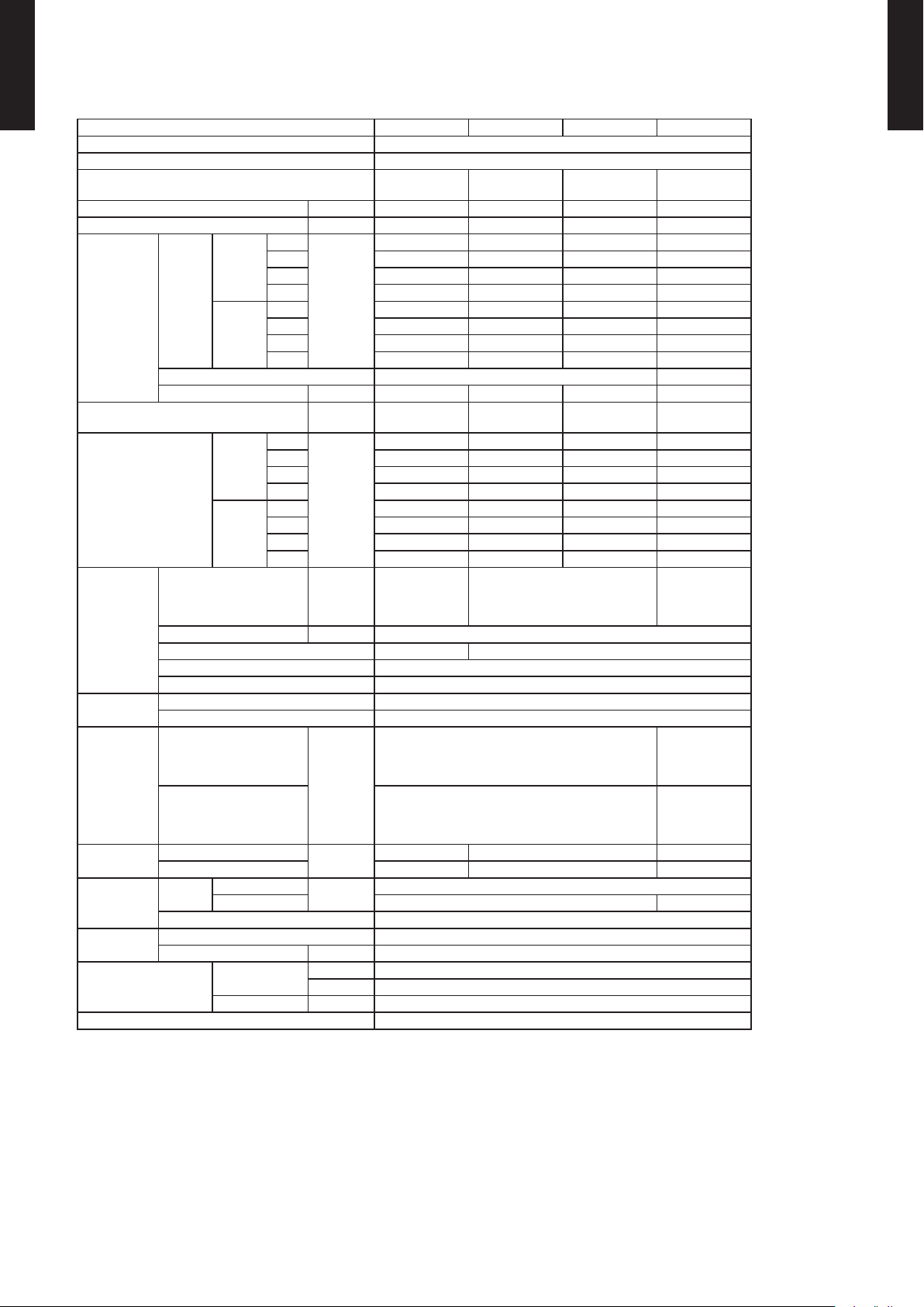
SLIM DUCT TYPE3-2.
MULTI TYPE
2, 3 ROOMS TYPE
Model name ARU7RLF ARU9RLF ARU12RLF ARU18RLF
Power source 1ø 208/230V 60Hz
Available voltage range 187-26 4V
Capacity
Input power W 33 49 58 73
Running current A 0.30 0.30 0.35 0.44
High
Cooling
Airow
Fan
Recommended static pressure in.WG (Pa)
Sound pressure level *
Heat
exchanger
Enclosure
Dimensions
(H × W ×D)
Weight
Connection
pipe
Drain hose
Operation range
Remote controller type Wired [Wireless(option)]
NOTE :
• Specications are based on the following conditions.
Standard static pressure : 0.10in.WG (25Pa)
• The protective function might work when using it outside the operation range.
*: These are the measured values in the manufacturer’s anechoic chamber.
Because of the surrounding sound environment, the sound levels measured in actual installation conditions might be higher than the
specied values here.
rate
Heating
Fan type × Q'ty Sirocco × 2 Sirocco × 3
Fan motor output W 80 81 81 81
Cooling
Heating
Dimension (H × W × D) in. (mm)
Fin pitch FPI 20
Rows × Stages 2 × 14 3 × 14
Pipe type Copper tube
Fin Type Aluminum
Material GALVANIZED STEEL SHEET
Color -
Net
Gross
Net
Gross 49 (22) 51 (23) 60 (27)
Size
Method Flare
Material HARD PVC
size in. [mm] Ø 1(I.D.), Ø 1-1/4(O.D.) [Ø 25(I.D.), Ø 32(O.D.)]
Liquid
Gas Ø3/8 (Ø9.52) Ø1/2 (Ø12.70)
Cooling
Heating °F (°C) 60 to 88 (16 to 31)
Med 288 (490) 324 (550) 353 (600) 518 (880)
Low 277 (470) 294 (500) 324 (550) 483 (820)
Quiet 259 (440) 265 (450) 283 (480) 442 (750)
High 324 (550) 353 (600) 383 (650) 554 (940)
Med 288 (490) 324 (550) 353 (600) 518 (880)
Low 277 (470) 294 (500) 324 (550) 483 (820)
Quiet 259 (440) 265 (450) 283 (480) 442 (750)
High
Med 26 27 28 31
Low 25 26 27 30
Quiet 24 25 26 29
High 28 28 29 33
Med 26 26 28 32
Low 25 25 27 31
Quiet 24 24 24 29
CFM
(m3/h)
dB(A)
in. (mm)
lbs. (kg)
in. (mm)
°F (°C) 64 to 90 (18 to 32)
%RH 80 or less
7,000 Btu/h
class
324 (550) 353 (600) 383 (650) 554 (940)
0 to 0.36
(0 to 90)
28 28 29 32
11-9/16 × 19-
11/16 × 1-1/16
(294 × 500 ×
26.6)
37 (17) 40 (18) 49 (22)
9,000 Btu/h
class
0 to 0.36
(0 to 90)
11-9/16 × 19-11/16 × 1-9/16
(294 × 500 × 39.9)
7-13/16 x 27-9/16 x 24-7/16
(198 × 700 × 620)
10-13/16 x 37-3/16 x 30-3/8
(274 × 945 × 772)
Ø1/4 (Ø6.35)
12,000 Btu/h
class
0 to 0.36
(0 to 90)
18,000 Btu/h
class
0 to 0.36
(0 to 90)
11-9/16 × 279/16 × 1-9/16
(294 × 700 ×
39.9)
7-13/16 x 35-
7/16 x 24-7/16
(198 × 900 ×
620)
10-13/16 x 45-
1/16 x 30-3/8
(274 × 1,145 ×
772)
MULTI TYPE
2, 3 ROOMS TYPE
- (01 - 24) -
Page 29
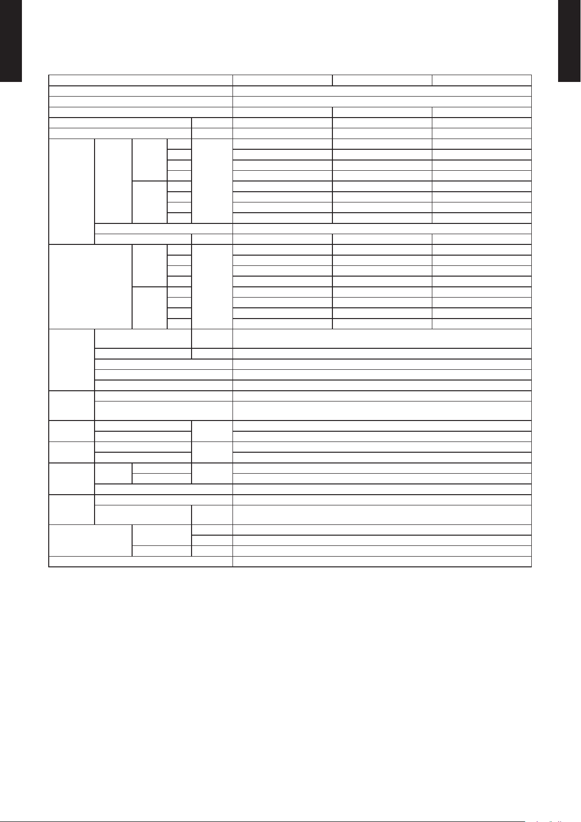
WALL MOUNTED TYPE3-3.
MULTI TYPE
2, 3 ROOMS TYPE
Model name ASU7RLF1 ASU9RLF1 ASU12RLF1
Power source 1ø 208/230V 60Hz
Available voltage range 187-26 4V
Capacity 7,000 Btu/h class 9,000 Btu/h class 12,000 Btu/h class
Input power W 15 17 22
Running current A 0.13 0.15 0.19
High
Cooling
Airow
Fan
Sound pressure level *
Heat
exchanger
Enclosure
Dimensions
(H × W ×D)
Weight
Connection
pipe
Drain hose
Operation range
Remote controller type Wireless [Wired(option)]
NOTE :
• The protective function might work when using it outside the operation range.
*: These are the measured values in the manufacturer’s anechoic chamber.
Because of the surrounding sound environment, the sound levels measured in actual installation conditions might be higher than the
specied values here.
rate
Heating
Fan type × Q'ty Cross ow × 1
Fan motor output W 30 30 30
Cooling
Heating
Dimension (H × W × D) in.(mm)
Fin pitch FPI Main: 23, Sub: 18
Rows × Stages Main: 2 x 20, Sub: 1 x 4
Pipe type Copper tube
Fin Type Aluminum
Material Polystyrene
Color
Net
Gross 10-5/8 × 34-13/16 × 14-3/4 (270 × 884 × 336)
Net
Gross 23 (10.5)
Size
Method Flare
Material PP + LLDPE
size in. [mm]
Liquid
Gas Ø3/8 (Ø9.52)
Cooling
Heating °F (°C) 60 to 86 (16 to 30)
Med 294 (500) 306 (520) 330 (560)
Low 253 (430) 253 (430) 265 (450)
Quiet 182 (310) 182 (310) 182 (310)
High 330 (560) 353 (600) 388 (660)
Med 294 (500) 306 (520) 330 (560)
Low 253 (430) 253 (430) 277 (470)
Quiet 194 (330) 194 (330) 194 (330)
High
Med 32 33 36
Low 29 29 30
Quiet 21 21 21
High 36 37 40
Med 32 33 36
Low 29 29 31
Quiet 22 22 22
CFM
(m3/h)
dB(A)
in. (mm)
lbs. (kg)
in.(mm)
°F (°C) 64 to 90 (18 to 32)
%RH 80 or less
330 (560) 353 (600) 388 (660)
36 37 40
Main: 12-5/8 x 24-13/16 x 13/16 (320 x 630 x 20)
Sub: 3-5/16 x 24-13/16 x 1/2 (84 x 630 x 13.3)
WHITE
(Approximate color of MUNSELL N9.25 /)
10-9/16 × 33-1/16 × 8 (268 × 840 × 203)
19 (8.5)
Ø1/4 (Ø6.35)
Ø 9/16(I.D.), Ø 5/8 to Ø 11/16(O.D.)
[Ø 13.8(I.D.), Ø 15.8 to Ø 16.7(O.D.)]
MULTI TYPE
2, 3 ROOMS TYPE
- (01 - 25) -
Page 30
MULTI TYPE
2, 3 ROOMS TYPE
Model name ASU18RLF
Power source 1ø 208/230V 60Hz
Available voltage range 187-26 4V
Capacity 18,000 Btu/h class
Input power W 41
Running current A 0.32
High
Cooling
Airow
Fan
Sound pressure level *
Heat
exchanger
Enclosure
Dimensions
(H × W × D)
Weight
Connection
pipe
Drain hose
Operation range
Remote controller type Wireless [Wired(option)]
NOTE :
• The protective function might work when using it outside the operation range.
*: These are the measured values in the manufacturer’s anechoic chamber.
Because of the surrounding sound environment, the sound levels measured in actual installation conditions might be higher than the
specied values here.
rate
Heating
Fan type × Q'ty Cross ow ×1
Fan motor output W 42
Cooling
Heating
Dimension (H × W × D) in. (mm)
Fin pitch FPI Main: 21, Sub: 18
Rows × Stages Main: 2 x 18, Sub: 1 x 4
Pipe type Copper tube
Fin Type Aluminum
Material Polystyrene
Color
Net
Gross 12-9/16 x 42-15/16 x 16-7/8 (319 × 1,090 × 429)
Net
Gross 40 (18)
Size
Method Flare
Material PVC
size in. [mm] Ø 1/2(I.D.), Ø 5/8(O.D.) [Ø 12(I.D.), Ø 16(O.D.)]
Liquid
Gas Ø1/2 (Ø12.70)
Cooling
Heating °F (°C) 60 to 88 (16 to 31)
Med 436 (740)
Low 365 (620)
Quiet 324 (550)
High 542 (920)
Med 436 (740)
Low 365 (620)
Quiet 324 (550)
High
Med 37
Low 33
Quiet 31
High 44
Med 37
Low 33
Quiet 31
CFM
(m3/h)
dB(A)
Main:15-7/8 x 33-3/4 x 1-1/16 (378 x 832 x 26.6)
Sub:3-5/16 x 33-3/4 x 1/2 (84 x 832 x 13.3)
(Approximate color of MUNSELL N9.25 /)
mm
lbs. (kg)
in. (mm)
°F (°C) 64 to 90 (18 to 32)
%RH 80 or less
12-5/8 x 39-1/4 x 9 (320 × 998 × 228)
542 (920)
43
WHITE
31 (14)
Ø1/4 (Ø6.35)
MULTI TYPE
2, 3 ROOMS TYPE
- (01 - 26) -
Page 31

FLOOR TYPE3-4.
MULTI TYPE
2, 3 ROOMS TYPE
Model name AGU9RLF AGU12RLF AGU15RLF
Power source 1ø 208/230V 60Hz
Available voltage range 18 7-2 6 4V
Capacity 9,000 Btu/h class 12,000 Btu/h class 14,000 Btu/h class
Input power W 16 20 23
Running current A 0.15 0.18 0.20
High
Cooling
Airow
Fan
Sound pressure level *
Heat
exchanger
Enclosure
Dimensions
(H × W × D)
Weight
Connection
pipe
Drain hose
Operation range
Remote controller type Wireless [Wired (option)]
NOTE :
• The protective function might work when using it outside the operation range.
*: These are the measured values in the manufacturer’s anechoic chamber.
Because of the surrounding sound environment, the sound levels measured in actual installation conditions might be higher than the
specied values here.
rate
Heating
Type × Q'ty Crossow x 2
Motor output W 16
Cooling
Heating
Dimension (H × W × D) in. (mm) 14-7/8 x 21-5/8 x 1-1/16 (378 × 550 × 26.6)
Fin pitch FPI 21
Rows × Stages 2 x 18
Pipe type Copper tube
Fin Type Aluminium
Material Polystyrene
Colour
Net
Gross 27-9/16 x 32-5/16 x 12-3/16 (700 × 820 × 310)
Net
Gross 37 (17)
Size
Method Flare
Material PVC
size in. (mm) Ø 9/16(I.D.), Ø 11/16(O.D.) [Ø 13.8 (I.D.), Ø 16.7 (O.D.)]
Liquid
Gas Ø3/8in. (Ø 9.52) Ø1/2in. (Ø 12.70)
Cooling
Heating °F (°C) 60 to 86 (16 to 30)
Med 259 (440) 288 (490) 306 (520)
Low 212 (360) 224 (380) 235 (400)
Quiet 159 (270) 159 (270) 159 (270)
High 312 (530) 353 (600) 383 (650)
Med 270 (460) 300 (510) 318 (540)
Low 224 (380) 241 (410) 253 (430)
Quiet 159 (270) 159 (270) 159 (270)
High
Med 34 36 38
Low 28 30 31
Quiet 22 22 22
High 39 42 44
Med 35 38 39
Low 30 32 33
Quiet 22 22 22
CFM
(m3/h)
dB(A)
in. (mm)
Ibs. (kg)
in. (mm)
°F (°C) 64 to 90 (18 to 32)
%RH 80 or less
312 (530) 353 (600) 383 (650)
39 42 44
WHITE
(Approximate colour of MUNSELL N9.25/)
23-5/8 x 29-1/8 x 7-7/8 (600 × 740 × 200)
31 (14)
Ø1/4in. (Ø 6.35)
MULTI TYPE
2, 3 ROOMS TYPE
- (01 - 27) -
Page 32

DIMENSIONS4.
(Drain hose)
20-7/8 (530): Hanging bolt position
4 (102)
5-5/16
(135)
9-13/16 (250)
27-9/16 (700)
27-9/16 (700)
2-15/16 (75)
1-3/16 (30)
1-3/16 (30)
10-5/16 (262)
21-1/4 (540): Hanging bolt position
□ 22-7/16 (570): Indoor unit
□ 22-13/16 to 26 (580 to 660)
: Ceiling openings
•
Cassette grille mounting state
Top view
5-14/16 to 7-7/8 (150 to 200)
Min. 17-11/16 (450)
Min. 17-11/16 (450)
Maintenance space
Side view
8-7/16 (215)
4-13/16 (123)
2-5/16 (58)
4-1/2 (114)
5-3/4 (146)
4-1/4
(108)
4 (102)
9-5/8 (245)
1-3/16 (30)
1-9/16 (40)
3-7/8 (99)
Drain port
Control box
Ceiling
Drain port
Be sure to leave
maintenance space
for future service
at the designated
position.
Bottom view
1-3/16 (30)
1-15/16 (49)
Side view
COMPACT CASSETTE TYPE4-1.
MULTI TYPE
2, 3 ROOMS TYPE
MODELS : AUU7RLF, AUU9RLF, AUU12RLF, AUU18RLF
Unit: in. (mm)
MULTI TYPE
2, 3 ROOMS TYPE
AUU7RLF, AUU9RLF,
AUU12RLF
Refrigerant pipe are
connection
Drain hose connection Drain hose I.D.: Ø 1 in.(Ø 25 mm), O.D.: Ø 1-1/4 in.(Ø 32 mm)
Liquid ø 1/4 in. (ø 6.35 mm) ø 1/4 in. (ø 6.35 mm)
Gas ø 3/8 in. (ø 9.52 mm) ø 1/2 in. (ø 12.70 mm)
- (01 - 28) -
AUU18RLF
Page 33

MULTI TYPE
40 (1,000)
or more
40 (1,000)
or more
95 (2,400)
or more
11 (262)
or more
Strong and durable ceiling
Obstruction
Floor
4 (100) or more
*
2, 3 ROOMS TYPE
INSTALLATION PLACE
Unit : in. (mm)
MULTI TYPE
2, 3 ROOMS TYPE
H
H (The maximum height from oor to ceiling)
Unit: in. (mm)
Model name AUU7 AUU9 AUU12 AUU18
Standard mode
107
(2,700)
107
(2,700)
107
(2,700)
107
(2,700)
High Ceiling mode - -
3-way directions setting
z
119
(3,000)
119
(3,000)
To set “3-way directions”, the air outlet shutter plate (UTR-YDZB) sold separately must be
installed and “outlet-direction” switched to “3-way” by remote controller.
*When installing the indoor unit, be careful about the maintenance space.
- (01 - 29) -
Page 34

SLIM DUCT TYPE4-2.
Rear view
View A
Top view
Side view
Front view
Bottom view
(Drain hose)
Drain port
2 (51)
22-5/8 (574)
6-17/8 (174)
2-13/16 (71)
6 (152)
3-15/16 (100) x 6 = 23-5/8 (600)
3-1/4 (82)
1-7/8 (48)
25-9/16 (650)
28-7/8 (734)
1-3/16 (30)
14-13/16 (377)
6-9/16 (167)
4-11/16 (119)
3-1/2 (89)
3-1/16 (78)
2-3/16 (55)
1-7/8 (47)
3/8 (10)
24-7/16 (620)
14-5/8 (371)
10-3/8 (264)
5-11/16 (144)
2-11/16 (69)
25-9/16 (650)
26-1/8 (664)
27-9/16 (700)
1-11/16 (43)
13/16 (20)
7-13/16 (198)
6-5/8 (168)
5-15/16 (151)
3-1/16 (78) 2-3/16 (55)
MULTI TYPE
2, 3 ROOMS TYPE
MODELS : ARU7RLF, ARU9RLF, ARU12RLF
Unit : in. (mm)
MULTI TYPE
2, 3 ROOMS TYPE
ARU7, ARU9, ARU12
Refrigerant pipe are
connection
Drain hose connection Drain hose I.D.: Ø 1 in.(Ø 25 mm), O.D.: Ø 1-1/4 in.(Ø 32 mm)
Liquid ø 1/4 in. (ø 6.35 mm)
Gas ø 3/8 in. (ø 9.52 mm)
- (01 - 30) -
Page 35

MODEL : ARU18RLF
Rear view
View A
Top view
Side view
Front view
Bottom view
(Drain hose)
Drain port
2 (51)
30-1/2 (774)
6-7/8 (174)
2-13/16 (71)
6 (152)
3-7/16 (87)
2-3/16 (56)
33-7/16 (850)
36-3/4 (934)
3-15/16 (100) x 8 = 31-1/2 (800)
1-3/16 (30)
14-13/16 (377)
6-9/16 (167)
4-11/16 (119)
3-1/2 (89)
3-1/16 (78)
2-3/16 (55)
1-7/8 (47)
3/8 (10)
24-7/16 (620)
14-5/8 (371)
10-3/8 (264)
5-11/16 (144)
2-11/16 (69)
33-7/16 (850)
34 (864)
35-7/16 (900)
1-11/16 (43)
13/16
(20)
7-13/16 (198)
6-5/8 (168)
5-15/16 (151)
3-1/16 (78)
2-3/16 (55)
Unit : in. (mm)
MULTI TYPE
2, 3 ROOMS TYPE
MULTI TYPE
2, 3 ROOMS TYPE
Refrigerant pipe are
connection
Drain hose connection Drain hose I.D.: Ø 1 in.(Ø 25 mm), O.D.: Ø 1-1/4 in.(Ø 32 mm)
Liquid ø 1/4 in. (ø 6.35 mm)
Gas ø 1/2 in. (ø 12.70 mm)
ARU18
- (01 - 31) -
Page 36

Left
side
Strong and durable ceiling
Indoor unit
Right
side
4 (100)
or more
12 (300)
or more
Service access Ceiling
99 (2,500) or more
(When no ceiling)
Floor
10 (240) or more
1 (20) or more
1 (20) or more
12 (300) or more
1 (10)
or less
1 (10)
or less
Left side
Strong and
durable floor
Right side
(PIPE side)
Grille
Inlet air
Strong and
durable floor
6
(150)
or more
4 (100)
or more
12 (300)
or more
1 (20)
or more
1 (20)
or more
6 (150)
or more
Left side
Strong and
durable floor
Right side
(PIPE side)
Duct
Grille
Inlet air
Strong and
durable floor
6
(150)
or more
4 (100)
or more
12 (300)
or more
1 (20)
or more
1 (20)
or more
6 (150)
or more
Unit : in. (mm)
MULTI TYPE
2, 3 ROOMS TYPE
INSTALLATION PLACE
MULTI TYPE
2, 3 ROOMS TYPE
- (01 - 32) -
Page 37

Service access
Unit
Control
box
or more
Service space
12 (300)
12 (300)
or more
4 (100)
or more
Unit : in. (mm)
MULTI TYPE
2, 3 ROOMS TYPE
MAINTENANCE SPACE
Provide a service access for inspection purposes as shown below.
Do not place any wiring or illumination in the service space, as they will impede service.
MULTI TYPE
2, 3 ROOMS TYPE
- (01 - 33) -
Page 38

WALL MOUNTED TYPE4-3.
33-1/16 (840) 8 (203)
10-9/16 (268)
33-1/16(840)
1-3/4(45)
2-1/16(52)
14-5/16(364)
Ø2-9/16 (Ø65)
for pipe inlet
12-5/8(321)
3-7/16
(88)
Ø2-9/16 (Ø65)
for pipe inlet
12-3/8(315)
4-9/16
(1 16)
1-5/8(41)
10-9/16(268)
13-7/8(353)
3-1/16(78)
11/16(18)7/16(11)
1-5/8(41)
MULTI TYPE
2, 3 ROOMS TYPE
MODELS : ASU7RLF1, ASU9RLF1, ASU12RLF1
Unit : in. (mm)
MULTI TYPE
2, 3 ROOMS TYPE
Refrigerant pipe are
connection
Liquid ø 1/4 in. (ø 6.35 mm)
Gas ø 3/8 in. (ø 9.52 mm)
Drain hose connection Drain hose
ASU7RLF1, ASU9RLF1, ASU12RLF1
I.D. 9/16 in. (13.8 mm), O.D. 5/8 to 11/16 in. (15.8 to 16.7 mm)
Drain hose : L=23-5/8 in. (600mm)
- (01 - 34) -
Page 39

MULTI TYPE
71 (1,800) or more
60 (1,500) or more
1 (25)
or more
Outline of unit
3 (70)
or more
3 (52)
or more
2 (45) or more
3 (63) or more
6 (130)
or more
2, 3 ROOMS TYPE
INSTALLATION PLACE
Unit : in. (mm)
MULTI TYPE
2, 3 ROOMS TYPE
- (01 - 35) -
Page 40

MULTI TYPE
39-5/16 (998)
17-1/4 (438)
15-5/8 (397)
12-5/8 (320): Unit size
2 (51)
2 (51)
13/16 (20)
2-5/8 (67)1-1/8 (28)
35-9/16 (903)
Ø 3-1/8 (80) hole
39-5/16 (998): Unit size
Outline of unit
Piping inlet
Unit center
9 (228)
12-5/8 (320)
20-1/2 (520)
20-1/2 (520)
23-1/4 (590)
28-3/8 (721)
Ø 3-1/8 (80) hole
Piping inlet
11/16 (17)
1 (25)
ø1-1/4 (32)
ø5/8 (16)
ø1/8 (12)
7/16 (11)
2, 3 ROOMS TYPE
MODELS : ASU18RLF
MULTI TYPE
2, 3 ROOMS TYPE
Unit : in. (mm)
Refrigerant pipe are
connection
Drain hose connection Drain hose
ASU18RLF
Liquid ø 1/4 in. (ø 6.35 mm)
Gas ø 1/2 in. (ø 12.70 mm)
I.D. 1/2 in. (12 mm) , O.D. 5/8 in. (16 mm)
Drain hose : L=26-3/8 in. (670mm)
- (01 - 36) -
Page 41

MULTI TYPE
3 (63) or more
4 (80) or more
3 (53) or more
3 (52) or more
4 (80) or more
Outline of unit
5 (120) or more
60 (1,500) or more
71 (1,800) or more
2, 3 ROOMS TYPE
INSTALLATION PLACE
MULTI TYPE
2, 3 ROOMS TYPE
Unit : in. (mm)
- (01 - 37) -
Page 42

FLOOR TYPE4-4.
23-5/8 (600)
7-7/8 (200)
Side view
Front view
29-1/8 (740)
4 (80)
or more
2 (50)
or more
from the floor
4 (80) or more
4 (100) or more
4 (100) or below
MULTI TYPE
2, 3 ROOMS TYPE
MODELS : AGU9RLF, AGU12RLF, AGU15RLF
Unit : in. (mm)
MULTI TYPE
2, 3 ROOMS TYPE
INSTALLATION PLACE
- (01 - 38) -
Page 43

WIRING DIAGRAMS5.
COMPACT CASSETTE TYPE5-1.
MULTI TYPE
2, 3 ROOMS TYPE
MODELS : AUU7RLF, AUU9RLF, AUU12RLF, AUU18RLF
MULTI TYPE
2, 3 ROOMS TYPE
- (01 - 39) -
Page 44

SLIM DUCT TYPE5-2.
MULTI TYPE
2, 3 ROOMS TYPE
MODELS : ARU7RLF, ARU9RLF, ARU12RLF, ARU18RLF
MULTI TYPE
2, 3 ROOMS TYPE
- (01 - 40) -
Page 45

WALL MOUNTED TYPE5-3.
MULTI TYPE
2, 3 ROOMS TYPE
MODELS : ASU7RLF1, ASU9RLF1, ASU12RLF1
MULTI TYPE
2, 3 ROOMS TYPE
- (01 - 41) -
Page 46

MULTI TYPE
2, 3 ROOMS TYPE
MODELS : ASU18RLF
MULTI TYPE
2, 3 ROOMS TYPE
- (01 - 42) -
Page 47

FLOOR TYPE5-4.
MULTI TYPE
2, 3 ROOMS TYPE
MODELS : AGU9RLF, AGU12RLF, AGU15RLF
MULTI TYPE
2, 3 ROOMS TYPE
- (01 - 43) -
Page 48

AIR VELOCITY AND TEMPERATURE DISTRIBUTIONS6.
7 (2.0)
7 (2.0)
7 (2.0)
7 (2.0)
3 (1.0)
3 (1.0)
3 (1.0)
3 (1.0)
2 (0.5)
2 (0.5)
2 (0.5)
2 (0.5)
1 (0.25)
1 (0.25)
1 (0.25)
1 (0.25)
7 (2.0)
3 (1.0)
2 (0.5) 2 (0.5)
1 (0.25) 1 (0.25)
COMPACT CASSETTE TYPE6-1.
Conditions
Fan speed : High
MULTI TYPE
2, 3 ROOMS TYPE
MODEL : AUU7RLF, AUU9RLF
Air velocity distribution
z
Operation mode : FAN
MULTI TYPE
2, 3 ROOMS TYPE
Top view
Vertical air ow direction louver : Up
(m)(f t.)
13
4
10
3
7
2
3
1
Unit : ft./s (m/s)
00
3
1
7
2
10
3
13
4
Side view
Vertical air ow direction louver : Up
(m)(f t.)
9
2.7
0
0
11
33 77 1010 1313
22 33 44
Unit : ft./s (m/s)
(m)
(f t.)
7
2
1
3
0
0
0
0
- (01 - 44) -
11
33 77 1010 1313
22 33 44
(m)
(f t.)
Page 49

7 (2.0) 7 (2.0)
5 (1.5) 5 (1.5)
3 (1.0) 3 (1.0)
2 (0.5) 2 (0.5)
1 (0.25) 1 (0.25)
86 (30) 86 (30)
82 (28) 82 (28)
79 (26) 79 (26)
75 (24) 75 (24)
72 (22) 72 (22)
Note: Reference data
Conditions
MULTI TYPE
2, 3 ROOMS TYPE
Air velocity distribution
z
Side view
Vertical air ow direction louver : Down
Fan speed : High
Operation mode : Heating
Vertical air ow direction louver:
Downward (4Way)
MULTI TYPE
2, 3 ROOMS TYPE
(m)(f t.)
9
2.7
8
2.5
7
2
1
3
0
0
Air temperature distribution
z
0
0
11
33 77 1010 1313
22 33 44
Unit : ft./s (m/s)
(m)
(f t.)
Side view
Vertical air ow direction louver : Down
(m)(f t.)
9
2.7
8
2.5
Unit : °F (°C)
7
2
1
3
0
0
0
0
11
33 77 1010 1313
22 33 44
(m)
(f t.)
- (01 - 45) -
Page 50

7 (2.0)
7 (2.0)
7 (2.0)
7 (2.0)
3 (1.0)
3 (1.0)
3 (1.0)
3 (1.0)
2 (0.5)
2 (0.5)
2 (0.5)
2 (0.5)
1 (0.25)
1 (0.25)
1 (0.25)
1 (0.25)
7 (2.0)
3 (1.0)
2 (0.5)
2 (0.5)
1 (0.25)
1 (0.25)
Conditions
Fan speed : High
MULTI TYPE
2, 3 ROOMS TYPE
MODEL : AUU12RLF
Air velocity distribution
z
Top view
Vertical air ow direction louver : Up
Operation mode : FAN
MULTI TYPE
2, 3 ROOMS TYPE
(m)(f t.)
13
4
10
3
7
2
3
1
00
3
1
Unit : ft./s (m/s)
7
2
10
3
13
4
0
0
11
33 77 1010 1313
22 33 44
(m)
(f t.)
Side view
Unit : ft./s (m/s)
Vertical air ow direction louver : Up
(m)(f t.)
9
2.7
7
2
1
3
0
0
0
0
11
33 77 1010 1313
22 33 44
(m)
(f t.)
- (01 - 46) -
Page 51

5 (1.5) 5 (1.5)
3 (1.0) 3 (1.0)
2 (0.5) 2 (0.5)
1 (0.25) 1 (0.25)
86 (30) 86 (30)
82 (28) 82 (28)
79 (26) 79 (26)
75 (24) 75 (24)
72 (22) 72 (22)
Note: Reference data
Conditions
MULTI TYPE
2, 3 ROOMS TYPE
Fan speed : High
Operation mode : Heating
MULTI TYPE
2, 3 ROOMS TYPE
Vertical air ow direction louver:
Air velocity distribution
z
Downward (4Way)
Side view
Vertical air ow direction louver : Down
(m)(f t.)
9
2.7
8
2.5
7
2
1
3
0
0
Air temperature distribution
z
0
0
11
33 77 1010 1313
22 33 44
Unit : ft./s (m/s)
(m)
(f t.)
Side view
Vertical air ow direction louver : Down
(m)(f t.)
9
2.7
8
2.5
Unit : °F (°C)
7
2
1
3
0
0
0
0
11
33 77 1010 1313
22 33 44
(m)
(f t.)
- (01 - 47) -
Page 52

7 (2.0)
7 (2.0)
7 (2.0)
7 (2.0)
3 (1.0)
3 (1.0)
3 (1.0)
3 (1.0)
2 (0.5)
2 (0.5)
2 (0.5)
2 (0.5)
1 (0.25)
1 (0.25)
1 (0.25)
1 (0.25)
7 (2.0)
3 (1.0)
2 (0.5)
2 (0.5)
1 (0.25)
1 (0.25)
Conditions
Fan speed : High
MULTI TYPE
2, 3 ROOMS TYPE
MODEL : AUU18RLF
Air velocity distribution
z
Top view
Vertical air ow direction louver : Up
Operation mode : FAN
MULTI TYPE
2, 3 ROOMS TYPE
(m)(f t.)
13
4
10
3
7
2
3
1
00
3
1
Unit : ft./s (m/s)
7
2
10
3
13
4
Side view
0
0
11
33 77 1010 1313
22 33 44
(m)
(f t.)
Vertical air ow direction louver : Up
Unit : ft./s (m/s)
(m)(f t.)
9
2.7
7
2
1
3
0
0
0
0
11
33 77 1010 1313
22 33 44
(m)
(f t.)
- (01 - 48) -
Page 53

5 (1.5) 5 (1.5)
3 (1.0) 3 (1.0)
2 (0.5) 2 (0.5)
1 (0.25) 1 (0.25)
7 (2.0) 7 (2.0)
86 (30) 86 (30)
82 (28) 82 (28)
79 (26) 79 (26)
75 (24) 75 (24)
72 (22) 72 (22)
Note: Reference data
Conditions
MULTI TYPE
2, 3 ROOMS TYPE
Air velocity distribution
z
Fan speed : High
Operation mode : Heating
Vertical air ow direction louver:
MULTI TYPE
2, 3 ROOMS TYPE
Downward (4Way)
Side view
Vertical air ow direction louver : Down
(m)(f t.)
9
2.7
8
2.5
7
2
1
3
0
0
Air temperature distribution
z
0
0
11
33 77 1010 1313
22 33 44
Unit : ft./s (m/s)
(m)
(f t.)
Side view
Vertical air ow direction louver : Down
(m)(f t.)
9
2.7
8
2.5
Unit : °F (°C)
7
2
1
3
0
0
0
0
11
33 77 1010 1313
22 33 44
(m)
(f t.)
- (01 - 49) -
Page 54

SLIM DUCT TYPE with Auto louver grille kit6-2.
MULTI TYPE
2, 3 ROOMS TYPE
MODEL : ARU7RLF
Note: This data is measured installing the Auto louver grille kit (option).
Air velocity distribution
z
(f t .)
(m)
7
2
3
Top view
Vertical air ow
direction louver : Up
Horizontal airow
direction louver : Center
1
0
0
3
1
7
2
7 (2)
3 (1)
Conditions
Fan speed : High
Operation mode : Fan
Voltage : 230V
Unit : ft./s (m/s)
2 (0.5)
109876543210 (m)
3229262320161310730 (f t .)
MULTI TYPE
2, 3 ROOMS TYPE
Top view
Vertical air ow
direction louver : Up
Horizontal airow
direction louver : Right & Left
(f t .)
16
13
10
7
3
0
3
7
10
13
(m)
5
4
3
2
1
0
1
2
3
4
Unit : ft./s (m/s)
2 (0.5)
3 (1)
7 (2)
7 (2)
3 (1)
2 (0.5)
Side view
Vertical air ow
direction louver : Up
Horizontal airow
direction louver : Center
16
(f t .)
10
8
7
3
0
5
(m)
3
2.5
2
1
0
7 (2)
- (01 - 50) -
3 (1)
109876543210 (m)
3229262320161310730 (f t .)
Unit : ft./s (m/s)
2 (0.5)
109876543210 (m)
3229262320161310730 (f t .)
Page 55

Reference Data
MULTI TYPE
2, 3 ROOMS TYPE
Note: This data is measured installing the Auto louver grille kit (option).
Air velocity distribution
z
(m)
(f t .)
3
10
2.5
Side view
Vertical air ow
direction louver : Down
Horizontal airow
direction louver : Center
Air temperature distribution
z
8
2
7
1
3
0
0
7 (2)
3 (1)
Conditions
Fan speed : High
Operation mode : Heating
Voltage : 230V
Unit : ft./s (m/s)
2 (0.5)
109876543210 (m)
3229262320161310730 (f t .)
MULTI TYPE
2, 3 ROOMS TYPE
Side view
Vertical air ow
direction louver : Down
Horizontal airow
direction louver : Center
(f t .)
10
8
7
3
0
(m)
3
2.5
2
1
0
86 (30)
82 (28)
79 (26)
Unit: °F (°C)
75 (24)
72 (22)
109876543210 (m)
3229262320161310730 (f t .)
- (01 - 51) -
Page 56

Conditions
MULTI TYPE
2, 3 ROOMS TYPE
MODEL : ARU9RLF
Note: This data is measured installing the Auto louver grille kit (option).
Air velocity distribution
z
(f t .)
(m)
7
2
3
Top view
Vertical air ow
direction louver : Up
Horizontal airow
direction louver : Center
1
0
0
3
1
7
2
7 (2)
3 (1)
Fan speed : High
Operation mode : Fan
Voltage : 230V
Unit : ft./s (m/s)
2 (0.5)
109876543210 (m)
3229262320161310730 (f t .)
MULTI TYPE
2, 3 ROOMS TYPE
Top view
Vertical air ow
direction louver : Up
Horizontal airow
direction louver : Right & Left
(f t .)
16
13
10
7
3
0
3
7
10
13
(m)
5
4
3
2
1
0
1
2
3
4
Unit : ft./s (m/s)
2 (0.5)
3 (1)
7 (2)
7 (2)
3 (1)
2 (0.5)
Side view
Vertical air ow
direction louver : Up
Horizontal airow
direction louver : Center
16
(f t .)
10
8
7
3
0
5
(m)
3
2.5
2
1
0
7 (2)
- (01 - 52) -
3 (1)
109876543210 (m)
3229262320161310730 (f t .)
Unit : ft./s (m/s)
2 (0.5)
109876543210 (m)
3229262320161310730 (f t .)
Page 57

Reference Data
MULTI TYPE
2, 3 ROOMS TYPE
Note: This data is measured installing the Auto louver grille kit (option).
Air velocity distribution
z
(m)
(f t .)
3
10
2.5
Side view
Vertical air ow
direction louver : Down
Horizontal airow
direction louver : Center
Air temperature distribution
z
8
2
7
1
3
0
0
7 (2)
3 (1)
Conditions
Fan speed : High
Operation mode : Heating
Voltage : 230V
Unit : ft./s (m/s)
2 (0.5)
109876543210 (m)
3229262320161310730 (f t .)
MULTI TYPE
2, 3 ROOMS TYPE
Side view
Vertical air ow
direction louver : Down
Horizontal airow
direction louver : Center
(f t .)
10
8
7
3
0
(m)
3
2.5
2
1
0
86 (30)
82 (28)
79 (26)
Unit: °F (°C)
75 (24)
72 (22)
109876543210 (m)
3229262320161310730 (f t .)
- (01 - 53) -
Page 58

Conditions
MULTI TYPE
2, 3 ROOMS TYPE
MODELS : ARU12RLF
Note: This data is measured installing the Auto louver grille kit (option).
Air velocity distribution
z
(f t .)
(m)
7
2
3
Top view
Vertical air ow
direction louver : Up
Horizontal airow
direction louver : Center
1
0
0
3
1
7
2
7 (2)
3 (1)
Fan speed : High
Operation mode : Fan
Voltage : 230V
Unit : ft./s (m/s)
2 (0.5)
109876543210 (m)
3229262320161310730 (f t .)
MULTI TYPE
2, 3 ROOMS TYPE
Top view
Vertical air ow
direction louver : Up
Horizontal airow
direction louver : Right & Left
(f t .)
16
13
10
7
3
0
3
7
10
13
(m)
5
4
3
2
1
0
1
2
3
4
Unit : ft./s (m/s)
2 (0.5)
3 (1)
7 (2)
7 (2)
3 (1)
2 (0.5)
Side view
Vertical air ow
direction louver : Up
Horizontal airow
direction louver : Center
16
(f t .)
10
8
7
3
0
5
(m)
3
2.5
2
1
0
7 (2)
- (01 - 54) -
3 (1)
109876543210 (m)
3229262320161310730 (f t .)
Unit : ft./s (m/s)
2 (0.5)
109876543210 (m)
3229262320161310730 (f t .)
Page 59

Reference Data
MULTI TYPE
2, 3 ROOMS TYPE
Note: This data is measured installing the Auto louver grille kit (option).
Air velocity distribution
z
(m)
(f t .)
3
10
2.5
Side view
Vertical air ow
direction louver : Down
Horizontal airow
direction louver : Center
8
2
7
1
3
0
0
7 (2)
3 (1)
Conditions
Fan speed : High
Operation mode : Heating
Voltage : 230V
Unit : ft./s (m/s)
2 (0.5)
109876543210 (m)
3229262320161310730 (f t .)
MULTI TYPE
2, 3 ROOMS TYPE
Air temperature distribution
z
(f t .)
10
Side view
Vertical air ow
direction louver : Down
Horizontal airow
direction louver : Center
8
7
3
0
(m)
3
2.5
2
1
0
86 (30)
82 (28)
79 (26)
Unit: °F (°C)
75 (24)
72 (22)
109876543210 (m)
3229262320161310730 (f t .)
- (01 - 55) -
Page 60

Conditions
MULTI TYPE
2, 3 ROOMS TYPE
MODELS : ARU18RLF
Note: This data is measured installing the Auto louver grille kit (option).
Air velocity distribution
z
(f t .)
(m)
7
2
3
Top view
Vertical air ow
direction louver : Up
Horizontal airow
direction louver : Center
1
0
0
3
1
7
2
7 (2)
3 (1)
Fan speed : High
Operation mode : Fan
Voltage : 230V
Unit : ft./s (m/s)
2 (0.5)
109876543210 (m)
3229262320161310730 (f t .)
MULTI TYPE
2, 3 ROOMS TYPE
Top view
Vertical air ow
direction louver : Up
Horizontal airow
direction louver : Right & Left
(f t .)
16
13
10
7
3
0
3
7
10
13
(m)
5
4
3
2
1
0
1
2
3
4
Unit : ft./s (m/s)
2 (0.5)
3 (1)
7 (2)
7 (2)
3 (1)
2 (0.5)
Side view
Vertical air ow
direction louver : Up
Horizontal airow
direction louver : Center
16
(f t .)
10
8
7
3
0
5
(m)
3
2.5
2
1
0
7 (2)
- (01 - 56) -
3 (1)
109876543210 (m)
3229262320161310730 (f t .)
Unit : ft./s (m/s)
2 (0.5)
109876543210 (m)
3229262320161310730 (f t .)
Page 61

Reference Data
MULTI TYPE
2, 3 ROOMS TYPE
Note: This data is measured installing the Auto louver grille kit (option).
Air velocity distribution
z
(m)
(f t .)
3
10
2.5
Side view
Vertical air ow
direction louver : Down
Horizontal airow
direction louver : Center
8
2
7
1
3
0
0
7 (2)
3 (1)
Conditions
Fan speed : High
Operation mode : Heating
Voltage : 230V
Unit : ft./s (m/s)
2 (0.5)
109876543210 (m)
3229262320161310730 (f t .)
MULTI TYPE
2, 3 ROOMS TYPE
Air temperature distribution
z
(f t .)
10
Side view
Vertical air ow
direction louver : Down
Horizontal airow
direction louver : Center
8
7
3
0
(m)
3
2.5
2
1
0
86 (30)
82 (28)
79 (26)
75 (24)
Unit: °F (°C)
72 (22)
109876543210 (m)
3229262320161310730 (f t .)
- (01 - 57) -
Page 62

WALL MOUNTED TYPE6-3.
7 (2.0)
7 (2.0)
2 (0.5)
2 (0.5)
3 (1.0)
3 (1.0)
7 (2.0)
2 (0.5)
3 (1.0)
2 (0.5)
7 (2.0)
3 (1.0)
7 (2.0)
3 (1.0) 2 (0.5)
MULTI TYPE
2, 3 ROOMS TYPE
MODEL : ASU7RLF1
(m)
(f t.)
2
7
Conditions
Fan speed : High
Operation mode : Fan
Unit : ft./s (m/s)
MULTI TYPE
2, 3 ROOMS TYPE
Top view
Vertical air ow
direction louver : Up
Horizontal airow
direction louver :
Center
Top view
Vertical air ow
direction louver : Up
Horizontal airow
direction louver : Right & Left
1
3
0
0
1
3
2
7
0 1 2 3 4 5 6 7 8 9
0 3 7 10 13 16 20 23 26 29
(m)
(f t.)
3
10
2
7
1
3
0
0
1
3
2
7
3
10
0 1 2 3 4 5 6 7 8
0 3 7 10 13 16 20 23 26
(m)
(f t.)
3
10
(m)
(f t.)
9
(m)
29
(f t.)
Side view
Vertical air ow
direction louver : Up
Horizontal airow
direction louver : Center
Side view
Vertical air ow
direction louver : Down
Horizontal airow
direction louver : Center
2
7
1
3
0
0
0 1 2 3 4 5 6 7 8
0 3 7 10 13 16 20 23 26
(f t.)
(m)
10
3
7
2
3
1
0
0
0 1 2 3 4 5 6 7 8
0 3 7 10 13 16 20 23 26
- (01 - 58) -
9
(m)
29
(f t.)
9
(m)
29
(f t.)
Page 63

7 (2.0)
7 (2.0)
2 (0.5)
2 (0.5)
3 (1.0)
3 (1.0)
3 (1.0) 2 (0.5)
7 (2.0)
3 (1.0)
2 (0.5)
7 (2.0)
Conditions
7 (2.0)
3 (1.0) 2 (0.5)
MULTI TYPE
2, 3 ROOMS TYPE
MODEL : ASU9RLF1
(m)
(f t.)
2
7
Fan speed : High
Operation mode : Fan
Unit : ft./s (m/s)
MULTI TYPE
2, 3 ROOMS TYPE
Top view
Vertical air ow
direction louver : Up
Horizontal airow
direction louver :
Center
Top view
Vertical air ow
direction louver : Up
Horizontal airow
direction louver : Right & Left
1
3
0
0
1
3
2
7
0 1 2 3 4 5 6 7 8 9
0 3 7 10 13 16 20 23 26 29
(m)
(f t.)
3
10
2
7
1
3
0
0
1
3
2
7
3
10
0 1 2 3 4 5 6 7 8
0 3 7 10 13 16 20 23 26
(m)
(f t.)
3
10
(m)
(f t.)
9
(m)
29
(f t.)
Side view
Vertical air ow
direction louver : Up
Horizontal airow
direction louver : Center
Side view
Vertical air ow
direction louver : Down
Horizontal airow
direction louver : Center
2
7
1
3
0
0
0 1 2 3 4 5 6 7 8
0 3 7 10 13 16 20 23 26
(f t.)
(m)
10
3
7
2
3
1
0
0
0 1 2 3 4 5 6 7 8
0 3 7 10 13 16 20 23 26
- (01 - 59) -
9
(m)
29
(f t.)
9
(m)
29
(f t.)
Page 64

7 (2.0)
7 (2.0)
2 (0.5)
2 (0.5)
3 (1.0)
3 (1.0)
3 (1.0)
2 (0.5)
7 (2.0)
7 (2.0)
3 (1.0)
2 (0.5)
Conditions
3 (1.0) 2 (0.5)
7 (2.0)
MULTI TYPE
2, 3 ROOMS TYPE
MODEL : ASU12RLF1
(m)
(f t.)
2
7
Fan speed : High
Operation mode : Fan
Unit : ft./s (m/s)
MULTI TYPE
2, 3 ROOMS TYPE
Top view
Vertical air ow
direction louver : Up
Horizontal airow
direction louver :
Center
Top view
Vertical air ow
direction louver : Up
Horizontal airow
direction louver : Right & Left
1
3
0
0
1
3
2
7
0 1 2 3 4 5 6 7 8 9
0 3 7 10 13 16 20 23 26 29
(m)
(f t.)
3
10
2
7
1
3
0
0
1
3
2
7
3
10
0 1 2 3 4 5 6 7 8
0 3 7 10 13 16 20 23 26
(m)
(f t.)
3
10
(m)
(f t.)
9
(m)
29
(f t.)
Side view
Vertical air ow
direction louver : Up
Horizontal airow
direction louver : Center
Side view
Vertical air ow
direction louver : Down
Horizontal airow
direction louver : Center
2
7
1
3
0
0
0 1 2 3 4 5 6 7 8
0 3 7 10 13 16 20 23 26
(f t.)
(m)
10
3
7
2
3
0
1
0
0 1 2 3 4 5 6 7 8
0 3 7 10 13 16 20 23 26
- (01 - 60) -
9
(m)
29
(f t.)
9
(m)
29
(f t.)
Page 65

MULTI TYPE
7 (2.0)
3 (1.0)
2 (0.5)
7 (2.0)
3 (1.0)
2 (0.5)
7 (2.0)
3 (1.0)
2 (0.5)
7 (2.0)
7 (2.0)
3 (1.0)
3 (1.0)
2 (0.5)
2 (0.5)
2, 3 ROOMS TYPE
MODEL : ASU18RLF
Conditions
Fan speed : High
Operation mode : Fan
MULTI TYPE
2, 3 ROOMS TYPE
Top view
Vertical air ow
direction louver : Up
Horizontal airow
direction louver : Center
Top view
Vertical air ow
direction louver : Up
Horizontal airow
direction louver : Right & Left
(m)(f t.)
7
2
1
3
0
0
1
3
2
7
0
0
(m)(f t.)
3310
7
2
3
1
00
1
3 7 10 13 16 20 23 26
2 3 4 5 6 7 8
Unit : ft./s (m/s)
(m)
(f t.)
Unit : ft./s (m/s)
Side view
Vertical air ow
direction louver : Up
Horizontal airow
direction louver : Center
Side view
Vertical air ow
direction louver : Down
Horizontal airow
direction louver : Center
3
1
7
2
10
0
0
(m)(f t.)
10
3
2
7
1
3
0
0
0
0
(m)(f t.)
10
3
2
7
1
3
1
3 7 10 13 16 20 23 26
1
3 7 10 13 16 20 23 26
2 3 4 5 6 7 8
Unit : ft./s (m/s)
2 3 4 5 6 7 8
Unit : ft./s (m/s)
(m)
(f t.)
(m)
(f t.)
0
0
0
1
3 7 10 13 16 20 23 26
2 3 4 5 6 7 8
(m)
(f t.)
0
- (01 - 61) -
Page 66

FLOOR TYPE6-4.
3(1.0)
2(0.5)
UPPER LOWER
3(1.0)
2(0.5)
3(1.0)
2(0.5)
3(1.0)
2(0.5)
3(1.0)
2(0.5)
MULTI TYPE
2, 3 ROOMS TYPE
MODELS : AGU9RLF, AGU12RLF, AGU15RLF
Conditions
(f t.)
(m)
7
2
1
3
Unit : ft./s (m/s)
Fan speed : High
Operation mode : Fan
Fan select : UPPER & LOWER
Top view
Vertical air ow
0
direction louver : Up
0
Horizontal airow
direction louver : Center
1
3
7
2
1
3
2
7
3
10
(m)
4
(f t.)
13
MULTI TYPE
2, 3 ROOMS TYPE
Top view
Vertical air ow
direction louver : Up
Horizontal airow
direction louver : Right & Left
Side view
Vertical air ow
direction louver : Up
Horizontal airow
direction louver : Center
(f t.)
(f t.)
10
2
7
Unit : ft./s (m/s)
3
10
Unit : ft./s (m/s)
(m)
4
(f t.)
13
(m)
7
2
1
3
0
0
1
3
7
2
(m)
3
2
7
1
3
1
3
Side view
Vertical air ow
direction louver : Down
Horizontal airow
direction louver : Center
(f t.)
10
0
0
(m)
3
2
7
1
3
0
0
1
3
1
3
2
7
2
7
3
10
Unit : ft./s (m/s)
3
10
(m)
4
(f t.)
13
(m)
4
(f t.)
13
- (01 - 62) -
Page 67

FAN PERFORMANCE CURVE7.
SLIM DUCT TYPE7-1.
MULTI TYPE
2, 3 ROOMS TYPE
MODEL : ARU7RLF
0.44 (110)
MULTI TYPE
2, 3 ROOMS TYPE
0.40 (100)
0.36 (90)
0.32 (80)
0.28 (70)
0.24 (60)
0.20 (50)
0.16 (40)
0.12 (30)
0.08 (20)
External Static Pressure [in.WG (Pa)]
0.04 (10)
0 (0)
Quiet (SP mode09)
Normal SP
upper limit
Quiet
(Normal SP)
SP mode00
upper limit
Quiet (SP mode00)
177
(300)
SP mode09
upper limit
235 294 412
(400) (500) (700)
Air Flow [CFM (m
3
/h)]
Hi (SP mode09)
SP mode09
lower limit
Hi (Normal SP)
Hi (SP mode00)
353
(600)
0.44 (110)
0.40 (100)
0.36 (90)
0.32 (80)
0.28 (70)
0.24 (60)
0.20 (50)
0.16 (40)
0.12 (30)
0.08 (20)
External Static Pressure [in.WG (Pa)]
0.04 (10)
0 (0)
177
(300)
Available air ow rate range (High level)
Hi (Normal SP)
Hi (SP mode02)
Hi (SP mode01)
Hi (SP mode00)
235 294
(400) (500)
Air Flow [CFM (m
3
*1
Hi (SP mode09)
Hi (SP mode08)
Hi (SP mode07)
Hi (SP mode06)
Hi (SP mode05)
Hi (SP mode04)
Hi (SP mode03)
412353
(700)(600)
/h)]
*1: Available air ow rate range when Auto louver grille (option) is installed.
Fan speed : High
Vertical air ow direction louver : Up
- (01 - 63) -
Page 68

MULTI TYPE
2, 3 ROOMS TYPE
Cooling
z
MULTI TYPE
2, 3 ROOMS TYPE
120
100
80
60
40
Capacity (%)
20
0
Heating
z
120
100
80
60
40
Capacity (%)
235
(400)
294
(500)
Capacity
Air Flow [CFM (m
Capacity
353
(600)
3
/h)]
412
(700)
471
(800)
20
0
235
(400)
294
(500)
353
(600)
Air Flow [CFM (m
3
/h)]
412
(700)
471
(800)
- (01 - 64) -
Page 69

MULTI TYPE
2, 3 ROOMS TYPE
MODEL : ARU9RLF
MULTI TYPE
2, 3 ROOMS TYPE
0.44 (110)
0.40 (100)
0.36 (90)
0.32 (80)
0.28 (70)
0.24 (60)
0.20 (50)
0.16 (40)
0.12 (30)
0.08 (20)
External Static Pressure [in.WG (Pa)]
0.04 (10)
0 (0)
SP mode09
upper limit
Quiet (SP mode09)
Normal SP
upper limit
SP mode00
upper limit
Quiet
(Normal SP)
Quiet (SP mode00)
177
(300)
Hi (SP mode09)
SP mode09
lower limit
Hi (Normal SP)
Hi (SP mode00)
235 294 471
(400) (500) (800)
Air Flow [CFM (m
3
/h)]
412353
(700)(600)
0.44 (110)
0.40 (100)
0.36 (90)
0.32 (80)
0.28 (70)
0.24 (60)
0.20 (50)
0.16 (40)
0.12 (30)
0.08 (20)
External Static Pressure [in.WG (Pa)]
0.04 (10)
0 (0)
177
(300)
Available air ow rate range (High level)
*1
Hi (SP mode09)
Hi (SP mode08)
Hi (SP mode07)
Hi (Normal SP)
Hi (SP mode02)
Hi (SP mode01)
Hi (SP mode00)
235 294 471
(400) (500) (800)
Air Flow [CFM (m
3
/h)]
Hi (SP mode06)
Hi (SP mode05)
Hi (SP mode04)
Hi (SP mode03)
412353
(700)(600)
*1: Available air ow rate range when Auto louver grille (option) is installed.
Fan speed : High
Vertical air ow direction louver : Up
- (01 - 65) -
Page 70

MULTI TYPE
2, 3 ROOMS TYPE
Cooling
z
MULTI TYPE
2, 3 ROOMS TYPE
120
100
80
60
40
Capacity (%)
20
0
Heating
z
120
100
80
235
(400)
Capacity
294
(500)
353
(600)
Air Flow [CFM (m
Capacity
3
/h)]
412
(700)
471
(800)
60
40
Capacity (%)
20
0
235
(400)
294
(500)
353
(600)
Air Flow [CFM (m
3
/h)]
412
(700)
471
(800)
- (01 - 66) -
Page 71

MULTI TYPE
2, 3 ROOMS TYPE
MODEL : ARU12RLF
MULTI TYPE
2, 3 ROOMS TYPE
0.44 (110)
0.40 (100)
0.36 (90)
0.32 (80)
0.28 (70)
0.24 (60)
0.20 (50)
0.16 (40)
0.12 (30)
0.08 (20)
External Static Pressure [in.WG (Pa)]
0.04 (10)
0 (0)
Quiet (SP mode09)
Normal SP
upper limit
Quiet
(Normal SP)
SP mode00
upper limit
Quiet (SP mode00)
177
(300)
SP mode09
upper limit
235 294 471
(400) (500) (800)
Air Flow [CFM (m
3
/h)]
Hi (SP mode09)
SP mode09
lower limit
Hi (Normal SP)
Hi (SP mode00)
412353
(700)(600)
0.44 (110)
0.40 (100)
0.36 (90)
0.32 (80)
0.28 (70)
0.24 (60)
0.20 (50)
0.16 (40)
0.12 (30)
0.08 (20)
External Static Pressure [in.WG (Pa)]
0.04 (10)
0 (0)
177
(300)
Available air ow rate range (High level)
*1
Hi (SP mode09)
Hi (Normal SP)
Hi (SP mode02)
Hi (SP mode01)
Hi (SP mode00)
235 294 471
(400) (500) (800)
3
Air Flow [CFM (m
/h)]
412353
(700)(600)
Hi (SP mode08)
Hi (SP mode07)
Hi (SP mode06)
Hi (SP mode05)
Hi (SP mode04)
Hi (SP mode03)
*1: Available air ow rate range when Auto louver grille (option) is installed.
Fan speed : High
Vertical air ow direction louver : Up
- (01 - 67) -
Page 72

MULTI TYPE
2, 3 ROOMS TYPE
Cooling
z
MULTI TYPE
2, 3 ROOMS TYPE
120
100
80
Capacity
60
40
Capacity (%)
20
0
Heating
z
294
(500)
353
(600)
Air Flow [CFM (m
412
(700)
3
/h)]
471
(800)
530
(900)
120
100
80
Capacity
60
40
Capacity (%)
20
0
294
(500)
353
(600)
Air Flow [CFM (m
412
(700)
3
/h)]
471
(800)
530
(900)
- (01 - 68) -
Page 73

MULTI TYPE
2, 3 ROOMS TYPE
MODEL : ARU18RLF
MULTI TYPE
2, 3 ROOMS TYPE
0.44 (110)
0.40 (100)
SP mode09
upper limit
Hi (SP mode09)
0.36 (90)
0.32 (80)
Quiet
(SP mode09)
0.28 (70)
0.24 (60)
0.20 (50)
0.16 (40)
0.12 (30)
0.08 (20)
External Static Pressure [in.WG (Pa)]
0.04 (10)
0.44 (110)
0.40 (100)
0 (0)
Normal SP
upper limit
Quiet (Normal
SP)
SP mode00
upper limit
Quiet
(SP mode00)
SP mode09
lower limit
Hi (Normal SP)
Hi (SP mode00)
412353 471 530 589 647 706
(700)(600) (800) (900) (1,000) (1,100) (1,200)
Air Flow [CFM (m3/h)]
Available air ow rate range (High level)
*1
0.36 (90)
0.32 (80)
0.28 (70)
0.24 (60)
0.20 (50)
0.16 (40)
0.12 (30)
0.08 (20)
External Static Pressure [in.WG (Pa)]
0.04 (10)
Hi (Normal SP)
Hi (SP mode02)
Hi (SP mode01)
Hi (SP mode00)
0 (0)
412353 471 530 589 647 706
(700)(600) (800) (900) (1,000) (1,100) (1,200)
Air Flow [CFM (m
*1: Available air ow rate range when Auto louver grille (option) is installed.
Fan speed : High
Vertical air ow direction louver : Up
3
/h)]
Hi (SP mode09)
Hi (SP mode08)
Hi (SP mode07)
Hi (SP mode06)
Hi (SP mode05)
Hi (SP mode04)
Hi (SP mode03)
- (01 - 69) -
Page 74

MULTI TYPE
2, 3 ROOMS TYPE
Cooling
z
MULTI TYPE
2, 3 ROOMS TYPE
120
100
80
Capacity
60
40
Capacity (%)
20
0
412
(700)
471
(800)
530
(900)
589
(1,000)
647
(1,100)
Air Flow [CFM (m3/h)]
Heating
z
120
100
80
Capacity
60
40
Capacity (%)
20
0
412
(700)
471
(800)
530
(900)
589
(1,000)
647
(1,100)
Air Flow [CFM (m3/h)]
- (01 - 70) -
Page 75

AIRFLOW8.
Typ e Model
MULTI TYPE
2, 3 ROOMS TYPE
Operation
mode
Cooling
AUU7RLF
Heating
Cooling
AUU9RLF
Heating
Compact
Cassette
Cooling
AUU12RLF
Heating
Cooling
AUU18RLF
Heating
Fan
speed
High 540 150 318
Med 490 136 288 Med 490 136 28 8
Low 440 122 259 Low 470 131 277
Quiet 390 108 230 Quiet 440 122 259
High 540 150 318
Med 490 136 288 Med 490 136 28 8
Low 440 122 259 Low 470 131 277
Quiet 390 108 230 Quiet 440 122 259
High 540 150 318
Med 490 136 288 Med 550 153 324
Low 440 122 259 Low 500 139 294
Quiet 390 108 230 Quiet 450 125 265
High 540 150 318
Med 490 136 288 Med 550 153 324
Low 440 122 259 Low 500 139 294
Quiet 390 108 230 Quiet 450 125 265
High 610 169 359
Med 530 147 312 Med 60 0 167 353
Low 470 131 277 Low 550 153 324
Quiet 410 114 241 Quiet 480 133 283
High 610 169 359
Med 530 147 312 Med 60 0 167 353
Low 470 131 277 Low 550 153 324
Quiet 410 114 241 Quiet 480 133 283
High 750 20 8 441
Med 610 169 359 Med 880 244 518
Low 520 144 306 Low 820 227 483
Quiet 410 114 241 Quiet 750 208 441
High 800 222 471
Med 710 197 418 Med 880 244 518
Low 600 167 353 Low 820 227 483
Quiet 450 125 265 Quiet 750 208 441
Air ow
3
/h l/s CFM m3/h l/s CFM
m
Typ e Model
ARU7RLF
ARU9RLF
Slim Duct
ARU12RLF
ARU18RLF
Operation
mode
Cooling
Heating
Cooling
Heating
Cooling
Heating
Cooling
Heating
Fan
speed
High 550 153 324
High 550 153 324
High 600 167 353
High 600 167 353
High 650 181 383
High 650 181 383
High 940 261 553
High 940 261 553
Air ow
MULTI TYPE
2, 3 ROOMS TYPE
Conversion Factor
1 m3/h = 0.2778 l/s = 0.5886 CFM
3.6 m3/h = 1 l/s
1.699 m3/h = 1 CFM
- (01 - 71) -
Page 76

Typ e Model
MULTI TYPE
2, 3 ROOMS TYPE
Operation
mode
Cooling
ASU7RLF1
Heating
Cooling
ASU9RLF1
Heating
Wall
Mounted
Cooling
ASU12RLF1
Heating
Cooling
ASU18RLF
Heating
Fan
speed
High 560 156 330
Med 500 139 294 Med 4 40 122 25 9
Low 430 119 25 3 Low 360 100 212
Quiet 310 86 182 Quiet 270 75 159
High 560 156 330
Med 500 139 294 Med 460 128 270
Low 430 119 25 3 Low 380 106 224
Quiet 330 92 194 Quiet 270 75 159
High 600 167 353
Med 520 144 306 Med 490 136 288
Low 430 119 25 3 Low 380 106 224
Quiet 310 86 182 Quiet 270 75 159
High 600 167 353
Med 520 144 306 Med 510 142 300
Low 430 119 25 3 Low 410 114 241
Quiet 330 92 194 Quiet 270 75 159
High 660 183 388
Med 560 156 330 Med 520 144 306
Low 450 125 265 Low 400 111 235
Quiet 310 86 182 Quiet 270 75 159
High 660 183 388
Med 560 156 330 Med 540 150 318
Low 470 131 277 Low 430 119 253
Quiet 330 92 194 Quiet 270 75 159
High 920 256 542
Med 740 20 6 436
Low 620 172 365
Quiet 550 153 324
High 920 256 542
Med 740 20 6 436
Low 620 172 365
Quiet 550 153 324
Air ow
3
m
/h l/s CFM m3/h l/s CFM
Typ e Model
AGU9RLF
Floor
AGU12RLF
AGU15RLF
Operation
mode
Cooling
Heating
Cooling
Heating
Cooling
Heating
Fan
speed
High 530 147 312
High 530 147 312
High 600 167 353
High 600 167 353
High 650 181 383
High 650 181 383
Air ow
MULTI TYPE
2, 3 ROOMS TYPE
Conversion Factor
1 m3/h = 0.2778 l/s = 0.5886 CFM
3.6 m3/h = 1 l/s
1.699 m3/h = 1 CFM
- (01 - 72) -
Page 77

NOISE LEVEL CURVE9.
0
10
20
30
40
50
60
70
80
63 12 5 250 500 1,000 2,00 0 4,000 8 ,000
NC -20
NC -40
NC -50
NC -60
NC -30
NC -15
NC -25
NC -35
NC -45
NC -55
NC -65
High
Quiet
0
10
20
30
40
50
60
70
80
63 12 5 250 500 1,000 2,00 0 4,000 8 ,000
NC -20
NC -40
NC -50
NC -60
NC -30
NC -15
NC -25
NC -35
NC -45
NC -55
NC -65
High
Quiet
0
10
20
30
40
50
60
70
80
63 125 250 500 1,000 2,000 4,000 8,000
NC-20
NC-40
NC-50
NC-60
NC-30
NC-15
NC-25
NC-35
NC-45
NC-55
NC-65
HIGH
QUIET
0
10
20
30
40
50
60
70
80
63 125 250 500 1,000 2,000 4,000 8,000
NC-20
NC-40
NC-50
NC-60
NC-30
NC-15
NC-25
NC-35
NC-45
NC-55
NC-65
HIGH
QUIET
COMPACT CASSETTE TYPE9-1.
MULTI TYPE
2, 3 ROOMS TYPE
MODEL : AUU7RLF
MULTI TYPE
2, 3 ROOMS TYPE
Cooling
z
Octave band sound pressure level, dB:(0dB=0.0002µbar)
z
Octave band sound pressure level, dB:(0dB=0.0002µbar)
Heating
Octave band center frequency, Hz
MODEL : AUU9RLF
Cooling
z
z
Heating
Octave band center frequency, Hz
Octave band sound pressure level, dB:(0dB=0.0002µbar)
Octave band center frequency, Hz
Octave band sound pressure level, dB:(0dB=0.0002µbar)
Octave band center frequency, Hz
- (01 - 73) -
Page 78

MULTI TYPE
0
10
20
30
40
50
60
70
80
63 12 5 250 500 1,000 2,00 0 4,000 8 ,000
NC -20
NC -40
NC -50
NC -60
NC -30
NC -15
NC -25
NC -35
NC -45
NC -55
NC -65
High
Quiet
0
10
20
30
40
50
60
70
80
63 12 5 250 500 1,000 2,00 0 4,000 8 ,000
NC -20
NC -40
NC -50
NC -60
NC -30
NC -15
NC -25
NC -35
NC -45
NC -55
NC -65
High
Quiet
0
10
20
30
40
50
60
70
80
63 12 5 250 500 1,000 2,00 0 4,000 8 ,000
NC -20
NC -40
NC -50
NC -60
NC -30
NC -15
NC -25
NC -35
NC -45
NC -55
NC -65
High
Quiet
0
10
20
30
40
50
60
70
80
63 12 5 250 500 1,000 2,00 0 4,000 8 ,000
NC -20
NC -40
NC -50
NC -60
NC -30
NC -15
NC -25
NC -35
NC -45
NC -55
NC -65
High
Quiet
2, 3 ROOMS TYPE
MODEL : AUU12RLF
MULTI TYPE
2, 3 ROOMS TYPE
Cooling
z
Octave band sound pressure level, dB:(0dB=0.0002µbar)
z
Octave band sound pressure level, dB:(0dB=0.0002µbar)
Heating
Octave band center frequency, Hz
MODEL : AUU18RLF
Cooling
z
Octave band sound pressure level, dB:(0dB=0.0002µbar)
z
Octave band sound pressure level, dB:(0dB=0.0002µbar)
Heating
Octave band center frequency, Hz
Octave band center frequency, Hz
Octave band center frequency, Hz
- (01 - 74) -
Page 79

SLIM DUCT TYPE9-2.
0
10
20
30
40
50
60
70
80
63 125 250 500 1,000 2,000 4,000 8,000
NC-20
NC-40
NC-50
NC-60
NC-30
NC-15
NC-25
NC-35
NC-45
NC-55
NC-65
HIGH
QUIET
0
10
20
30
40
50
60
70
80
63 125 250 500 1,000 2,000 4,000 8,000
NC-20
NC-40
NC-50
NC-60
NC-30
NC-15
NC-25
NC-35
NC-45
NC-55
NC-65
HIGH
QUIET
0
10
20
30
40
50
60
70
80
63 12 5 250 500 1,000 2,00 0 4,000 8 ,000
NC -20
NC -40
NC -50
NC -60
NC -30
NC -15
NC -25
NC -35
NC -45
NC -55
NC -65
High
Quiet
0
10
20
30
40
50
60
70
80
63 12 5 250 500 1,000 2,00 0 4,000 8 ,000
NC -20
NC -40
NC -50
NC -60
NC -30
NC -15
NC -25
NC -35
NC -45
NC -55
NC -65
High
Quiet
MULTI TYPE
2, 3 ROOMS TYPE
MODEL : ARU7RLF
MULTI TYPE
2, 3 ROOMS TYPE
Cooling
z
Octave band sound pressure level, dB:(0dB=0.0002µbar)
z
Octave band sound pressure level, dB:(0dB=0.0002µbar)
Heating
Octave band center frequency, Hz
MODEL : ARU9RLF
Cooling
z
Octave band sound pressure level, dB:(0dB=0.0002µbar)
z
Octave band sound pressure level, dB:(0dB=0.0002µbar)
Heating
Octave band center frequency, Hz
Octave band center frequency, Hz
Octave band center frequency, Hz
- (01 - 75) -
Page 80

MULTI TYPE
0
10
20
30
40
50
60
70
80
63 12 5 250 500 1,000 2,00 0 4,000 8 ,000
NC -20
NC -40
NC -50
NC -60
NC -30
NC -15
NC -25
NC -35
NC -45
NC -55
NC -65
High
Quiet
0
10
20
30
40
50
60
70
80
63 12 5 250 500 1,000 2,00 0 4,000 8 ,000
NC -20
NC -40
NC -50
NC -60
NC -30
NC -15
NC -25
NC -35
NC -45
NC -55
NC -65
High
Quiet
0
10
20
30
40
50
60
70
80
63 12 5 250 500 1,000 2,00 0 4,000 8 ,000
NC -20
NC -40
NC -50
NC -60
NC -30
NC -15
NC -25
NC -35
NC -45
NC -55
NC -65
High
Quiet
0
10
20
30
40
50
60
70
80
63 12 5 250 500 1,000 2,00 0 4,000 8 ,000
NC -20
NC -40
NC -50
NC -60
NC -30
NC -15
NC -25
NC -35
NC -45
NC -55
NC -65
High
Quiet
2, 3 ROOMS TYPE
MODEL : ARU12RLF
MULTI TYPE
2, 3 ROOMS TYPE
Cooling
z
Octave band sound pressure level, dB:(0dB=0.0002µbar)
z
Octave band sound pressure level, dB:(0dB=0.0002µbar)
Heating
Octave band center frequency, Hz
MODEL : ARU18RLF
Cooling
z
z
Heating
Octave band center frequency, Hz
Octave band sound pressure level, dB:(0dB=0.0002µbar)
Octave band center frequency, Hz
Octave band sound pressure level, dB:(0dB=0.0002µbar)
Octave band center frequency, Hz
- (01 - 76) -
Page 81

WALL MOUNTED TYPE9-3.
0
10
20
30
40
50
60
70
80
63
125
250
500
1000
2000
4000
8000
N C -2 0
N C -4 0
N C -5 0
N C -6 0
N C -3 0
N C -1 5
N C -2 5
N C -3 5
N C -4 5
N C -5 5
N C -6 5
HIGH
QUIET
0
10
20
30
40
50
60
70
80
63
125
250
500
1000
2000
4000
8000
N C -2 0
N C -4 0
N C -5 0
N C -6 0
N C -3 0
N C -1 5
N C -2 5
N C -3 5
N C -4 5
N C -5 5
N C -6 5
HIGH
QUIET
0
10
20
30
40
50
60
70
80
63
125
250
500
1000
2000
4000
8000
N C -2 0
N C -4 0
N C -5 0
N C -6 0
N C -3 0
N C -1 5
N C -2 5
N C -3 5
N C -4 5
N C -5 5
N C -6 5
HIGH
QUIET
0
10
20
30
40
50
60
70
80
63
125
250
500
1000
2000
4000
8000
N C -2 0
N C -4 0
N C -5 0
N C -6 0
N C -3 0
N C -1 5
N C -2 5
N C -3 5
N C -4 5
N C -5 5
N C -6 5
HIGH
QUIET
MULTI TYPE
2, 3 ROOMS TYPE
MODEL : ASU7RLF1
Cooling
z
Heating
z
MULTI TYPE
2, 3 ROOMS TYPE
Octave band sound pressure level, dB:(0 dB= 0.0002µbar)
Octave band center frequency,Hz
Octave band sound pressure level, dB:(0 dB= 0.0002µbar)
Octave band center frequency,Hz
MODEL : ASU9RLF1
Cooling
z
Heating
z
Octave band sound pressure level, dB:(0 dB= 0.0002µbar)
Octave band center frequency,Hz
Octave band sound pressure level, dB:(0 dB= 0.0002µbar)
Octave band center frequency,Hz
- (01 - 77) -
Page 82

MULTI TYPE
0
10
20
30
40
50
60
70
80
63
125
250
500
1000
2000
4000
8000
N C -2 0
N C -4 0
N C -5 0
N C -6 0
N C -3 0
N C -1 5
N C -2 5
N C -3 5
N C -4 5
N C -5 5
N C -6 5
HIGH
QUIET
0
10
20
30
40
50
60
70
80
63
125
250
500
1000
2000
4000
8000
N C -2 0
N C -4 0
N C -5 0
N C -6 0
N C -3 0
N C -1 5
N C -2 5
N C -3 5
N C -4 5
N C -5 5
N C -6 5
HIGH
QUIET
2, 3 ROOMS TYPE
MODEL : ASU12RLF1
Cooling
z
Heating
z
MULTI TYPE
2, 3 ROOMS TYPE
Octave band sound pressure level, dB:(0 dB= 0.0002µbar)
Octave band center frequency,Hz
Octave band sound pressure level, dB:(0 dB= 0.0002µbar)
Octave band center frequency,Hz
- (01 - 78) -
Page 83

MULTI TYPE
0
10
20
30
40
50
60
70
80
63 12 5 250 500 1,000 2,00 0 4,000 8 ,000
NC -20
NC -40
NC -50
NC -60
NC -30
NC -15
NC -25
NC -35
NC -45
NC -55
NC -65
High
Quiet
0
10
20
30
40
50
60
70
80
63 12 5 250 500 1,000 2,00 0 4,000 8 ,000
NC -20
NC -40
NC -50
NC -60
NC -30
NC -15
NC -25
NC -35
NC -45
NC -55
NC -65
High
Quiet
2, 3 ROOMS TYPE
MODEL : ASU18RLF
MULTI TYPE
2, 3 ROOMS TYPE
Cooling
z
Octave band sound pressure level, dB:(0dB=0.0002µbar)
z
Octave band sound pressure level, dB:(0dB=0.0002µbar)
Heating
Octave band center frequency, Hz
Octave band center frequency, Hz
- (01 - 79) -
Page 84

FLOOR TYPE9-4.
0
10
20
30
40
50
60
70
80
63 125 250 500 1,000 2,000 4,000 8,000
NC-20
NC-40
NC-50
NC-60
NC-30
NC-15
NC-25
NC-35
NC-45
NC-55
NC-65
Quiet
High
0
10
20
30
40
50
60
70
80
63 125 250 500 1,000 2,000 4,000 8,000
NC-20
NC-40
NC-50
NC-60
NC-30
NC-15
NC-25
NC-35
NC-45
NC-55
NC-65
Quiet
High
0
10
20
30
40
50
60
70
80
63 125 250 500 1,000 2,000 4,000 8,000
NC-20
NC-40
NC-50
NC-60
NC-30
NC-15
NC-25
NC-35
NC-45
NC-55
NC-65
Quiet
High
0
10
20
30
40
50
60
70
80
63 125 250 500 1,000 2,000 4,000 8,000
NC-20
NC-40
NC-50
NC-60
NC-30
NC-15
NC-25
NC-35
NC-45
NC-55
NC-65
Quiet
High
MULTI TYPE
2, 3 ROOMS TYPE
MODEL : AGU9RLF
MULTI TYPE
2, 3 ROOMS TYPE
Cooling
z
Octave band sound pressure level, dB:(0dB=0.0002µbar)
z
Octave band sound pressure level, dB:(0dB=0.0002µbar)
Heating
Octave band center frequency, Hz
Octave band center frequency, Hz
MODEL : AGU12RLF
Cooling
z
z
Heating
Octave band sound pressure level, dB:(0dB=0.0002µbar)
Octave band center frequency, Hz
Octave band sound pressure level, dB:(0dB=0.0002µbar)
Octave band center frequency, Hz
- (01 - 80) -
Page 85

MULTI TYPE
0
10
20
30
40
50
60
70
63 125 250 500 1,000 2,000 4,000 8,000
NC-20
NC-40
NC-50
NC-60
NC-30
NC-15
NC-25
NC-35
NC-45
NC-55
NC-65
Quiet
High
0
10
20
30
40
50
60
70
80
63 125 250 500 1,000 2,000 4,000 8,000
NC-20
NC-40
NC-50
NC-60
NC-30
NC-15
NC-25
NC-35
NC-45
NC-55
NC-65
Quiet
High
2, 3 ROOMS TYPE
MODEL : AGU15RLF
MULTI TYPE
2, 3 ROOMS TYPE
Cooling
z
Octave band sound pressure level, dB:(0dB=0.0002µbar)
z
Octave band sound pressure level, dB:(0dB=0.0002µbar)
Heating
Octave band center frequency, Hz
Octave band center frequency, Hz
- (01 - 81) -
Page 86

SOUND LEVEL CHECK POINT9-5.
Microphone
Microphone
60in. (1.5m)
MULTI TYPE
2, 3 ROOMS TYPE
COMPACT CASSETTE TYPE
MULTI TYPE
2, 3 ROOMS TYPE
- (01 - 82) -
Page 87

MULTI TYPE
CenterCenter
Front viewSide view
60in. (1.5m)
79in. (2m) 40in. (1m)
Microphone
Measuring duct Measuring duct
Microphone
40in. (1m)
32in. (0.8m)
Microphone Microphone
2, 3 ROOMS TYPE
SLIM DUCT TYPE
WALL MOUNTED TYPE
MULTI TYPE
2, 3 ROOMS TYPE
- (01 - 83) -
Page 88

MULTI TYPE
Microphone
Air Flow
Air Flow
40in. (1m)
40in. (1m)
Microphone
2, 3 ROOMS TYPE
FLOOR TYPE
MULTI TYPE
2, 3 ROOMS TYPE
- (01 - 84) -
Page 89

ELECTRIC CHARACTERISTICS10.
Power Supply Indoor Rated
MULTI TYPE
2, 3 ROOMS TYPE
Type Model name Hz
AUU7RLF 60 208 / 230 0.19 / 0.19 17 / 18 0.15 / 0.15
Compact Cassette
Slim Duct
Wall Mounted
Floor
AUU9RLF 60 208 / 230 0.19 / 0.19 17 / 18 0.15 / 0.15
AUU12RLF 60 208 / 230 0.24 / 0.24 22 / 23 0.19 / 0.19
AUU18RLF 60 208 / 230 0.41 / 0.38 38 / 39 0.32 / 0.30
ARU7RLF 60 208 / 230 0.40 / 0.41 47 / 33 0.32 / 0.30
ARU9RL F 60 208 / 230 0.40 / 0.38 47 / 49 0.32 / 0.30
ARU12RLF 60 208 / 230 0.47 / 0.44 56 / 58 0.37 / 0.35
ARU18RLF 60 208 / 230 0.59 / 0.55 71 / 73 0.47 / 0.44
ASU7RLF1 60 208 / 230 0.18 / 0.16 15 / 15 0.14 / 0.13
ASU9RLF1 60 208 / 230 0.20 / 0.19 17 / 17 0.16 / 0.15
ASU12RLF1 60 208 / 230 0.25 / 0.24 22 / 22 0.20 / 0.19
ASU18RLF 60 208 / 230 0.42 / 0.40 40 / 41 0.34 / 0.32
AGU9RLF 60 208 / 230 0.36 / 0.33 35 / 32 0.29 / 0.26
AGU12RLF 60 208 / 230 0.36 / 0.33 35 / 32 0.29 / 0.26
AGU15RLF 60 208 / 230 0.41 / 0.38 40 / 36 0.33 / 0.30
Voltage
(V)
MCA
(A)
Input Power
(W)
FLA
(A)
MULTI TYPE
2, 3 ROOMS TYPE
Wiring spec.
(Indoor unit to outdoor
unit)
Connection cable AWG 14
Limited wiring length [ft. (m)] 85 (26)
MCA : Min Circuit Amps = Max Operating Current (Full Load).
FLA : Full Load Amps.
- (01 - 85) -
Page 90

SAFETY DEVICES11.
MULTI TYPE
2, 3 ROOMS TYPE
Compact Cassette
Wall Mounted
Model and type PCB fuse
AUU7RLF
AUU9RLF
AUU12RLF
AUU18RLF
ARU7RLF
Slim Duct
Floor
ARU9RL F
ARU12RLF
ARU18RLF
ASU7RLF1
ASU9RLF1
ASU12RLF1
ASU18RLF 250V 3.15A
AGU9RLF
AGU15RLF
250V 3.15A
250V 3.15A
250V 3.15A
250V 3.15A
Fan motor
thermal
protector
OFF: 212 ± 18°F
(100 ± 10°C)
ON: 203 ± 18°F
(95 ± 10°C)
OFF: 275 ± 27°F
(135 ± 15°C)
ON: 239 ± 27°F
(115 ± 15°C)
OFF: 221 ± 18°F
(105 ± 10°C)
ON: 194 ± 18°F
(90 ± 10°C)
OFF: 302 ± 27°F
(150 ± 15°C)
ON: 248 ± 27°F
(120 ± 15°C)
OFF: 302 ± 27°F
(150 ± 15°C)
ON: 248 ± 27°F
(120 ± 15°C)
Terminal
thermal fuse
―
―
― ―
OFF: 216°F
(OFF: 102°C)
OFF: 216°F
(OFF: 102°C)
Float
switch
○
○
―
―AGU12RLF
MULTI TYPE
2, 3 ROOMS TYPE
- (01 - 86) -
Page 91

EXTERNAL INPUT & OUTPUT12.
Indoor unit
control PC board *1
Connector
1
3
Signal
Field supply
33ft. (10m) *2
Connected unit
Ex.) Switch
EXTERNAL INPUT
MULTI TYPE
2, 3 ROOMS TYPE
Indoor unit type
Compact Cassette
Slim Duct
Control input
● ● ● ― ―
● ● ● ● ―
Operation status
output
EXTERNAL OUTPUT
Fresh air control
output
Auxiliary heater
output
Error status output
MULTI TYPE
2, 3 ROOMS TYPE
●
Wall Mounted
Floor
● ● ― ―
● ● ― ― ●
(ASU7RLF1
ASU9RLF1
ASU12RLF1)
EXTERNAL INPUT12-1.
CONTROL INPUT (Operation/Stop or Forced stop)
Compact
Cassette
Connector CN102 CN102 CNA01 CN14 CN14
The air conditioner can be remotely operated by means of the following on-site work.
"Operation/Stop" mode or "Forced stop" mode can be selected with function setting of indoor unit.
Operation is started at the following contents by adding the contact input of a commercial ON/OFF switch to a
connector on the external control PC board and turning it ON.
Operation mode Auto changeover Mode at previous operation
Set temperature 76°F (24°C) Temperature at previous operation
Air ow mode AUTO Mode at previous operation
Air direction (swing) Standard air direction (swing OFF) Air direction at previous operation
Slim Duct
Initial starting after power turned on Starting other than at the left
Wall Mounted Floor
ASU7RLF1
ASU9RLF1
ASU12RLF1
ASU18RLF
AGU9RLF
AGU12RLF
AGU15RLF
Circuit diagram example
z
*1: PC board of Communication kit is used for Wall mounted (ASU7RLF1, ASU9RLF1, ASU12RLF1) type.
*2: Make the distance from the PC board to the connected unit within 33ft. (10m).
Indoor unit type
Compact Cassette - +
Slim Duct - +
Wall Mounted
Floor AGU9RLF, AGU12RLF, AGU15RLF
ASU7RLF1, ASU9RLF1, ASU12RLF1,
ASU18RLF
Contact capacity : 24VDC or more, 10mA or more.
1 Pin
(Polarity)
- +
- +
3 Pin
(Polarity)
- (01 - 87) -
Page 92

When function setting is "Operation/Stop" mode ●
Operation
Stop
ON
OFF
Input signal
Indoor unit
Remote controller
On On On
Input signal
On
Off
Indoor unit
Operation
Stop
Command
Forced stop
Normal
Remote control
operation invalidity
MULTI TYPE
2, 3 ROOMS TYPE
MULTI TYPE
2, 3 ROOMS TYPE
When function setting is "Forced stop" mode ●
Parts (Optional)
z
Compact
Cassette
Parts name External connect kit
Model name UT Y-XWZX UT D-ECS5A
Compact
Cassette
Parts name ― ― Communication kit ― ―
Model name ― ― UT Y-XCBXZ2 ― ―
* For operating the EXTERNAL INPUT function, the Wall mounted (ASU7RLF1, ASU9RLF1, ASU12RLF1) type requires
the communication kit (UTY-XCBXZ2) in addition to the wire (UTY-XWZXZ5).
Slim Duct
(UTD-ECS5A)(U T Y-XWZX)
Slim Duct
Wall Mounted Floor
ASU7RLF1
ASU9RLF1
ASU12RLF1
UT Y-
XWZXZ5
ASU7RLF1
ASU9RLF1
ASU12RLF1
ASU18RLF
UT Y-XWZ X
Wall Mounted Floor
ASU18RLF
AGU9RLF
AGU12RLF
AGU15RLF
UT Y-
XWZXZ5
(U T Y-XWZX Z5)
AGU9RLF
AGU12RLF
AGU15RLF
- (01 - 88) -
Page 93

EXTERNAL OUTPUT12-2.
Field supply
Ex.)Display
Indoor unit
control PC board *1
Connected unit
Ex.)Relay unit
1
2
Signal
Relay
power
supply
V
Connector
33ft. (10m)
*2
24V DC
ON
OFF
Operation
Stop
Indoor unit
Output signal
MULTI TYPE
2, 3 ROOMS TYPE
OPERATION STATUS OUTPUT
MULTI TYPE
2, 3 ROOMS TYPE
Compact
Cassette
Connector CN103 CN103 CNB01 CN16 CN20
Slim Duct
Wall Mounted Floor
ASU7RLF1
ASU9RLF1
ASU12RLF1
ASU18RLF
AGU9RLF
AGU12RLF
AGU15RLF
An air conditioner operation status signal can be output.
Circuit diagram example
z
Relay spec.:
Ma x.24V D C, 10mA to l ess
than 500mA.
*1: PC board of Communication kit is used for Wall mounted (ASU7RLF1, ASU9RLF1, ASU12RLF1) type.
*2: Make the distance from the PC board to the connected unit within 33ft. (10m).
Parts (Optional)
z
Parts name External connect kit
Model name UT Y-XWZX UT D-ECS5A
Parts name ― ― Communication kit ― ―
Model name ― ― UT Y-XCBXZ2 ― ―
* For operating the EXTERNAL OUTPUT function, the Wall mounted (ASU7RLF1, ASU9RLF1, ASU12RLF1) type
requires the communication kit (UTY-XCBXZ2) in addition to the wire (UTY-XWZXZ5).
Compact
Cassette
Compact
Cassette
Slim Duct
Slim Duct
Wall Mounted Floor
ASU7RLF1
ASU9RLF1
ASU12RLF1
UT Y-
XWZXZ5
ASU7RLF1
ASU9RLF1
ASU12RLF1
ASU18RLF
UT Y-XWZ X
Wall Mounted Floor
ASU18RLF
- (01 - 89) -
AGU9RLF
AGU12RLF
AGU15RLF
UT Y-
XWZXZ5
AGU9RLF
AGU12RLF
AGU15RLF
Page 94

MULTI TYPE
Field supply
Indoor unit
control PC board
Connector
1
12 V
on/off
2
Signal
Relay
power
supply
Ex.) Fan
Connected unit
Ex.) Relay unit
*33ft.
(10m)
ON
OFF
Operation
Stop
Indoor fan
Output signal
2, 3 ROOMS TYPE
FRESH AIR CONTROL OUTPUT
Compact Cassette Slim Duct Wall Mounted Floor
MULTI TYPE
2, 3 ROOMS TYPE
Connector CN6 CN6 ― ―
A signal linked to air conditioner indoor fan ON can be output.
* However, signal becomes OFF during cold air prevention control operation.
Circuit diagram example
z
Relay spec.:
Rated 12V DC, 50mA to less.
* Make the distance from the PC board to the connected unit within 33ft. (10m).
Parts (Optional)
z
Compact Cassette Slim Duct Wall Mounted Floor
Parts name
Fresh air intake kit External control set
― ―
Model name UTZ-VXAA *1 UTD-ECS5A ― ―
Note
*1: Please prepare External control set (UTD-ESC5A) when using it excluding Fresh air intake kit
(UTZ-V XA A).
- (01 - 90) -
Page 95

MULTI TYPE
Field supply
Indoor unit
control PC board
Connector
1
12 V
on/off
2
Signal
Relay
power
supply
Ex.) Heater
Connected unit
Ex.) Relay unit
*33ft.
(10m)
ON
OFF
Operation
Stop
Heating
operation
Indoor unit fan
ON
OFF
Output signal
1min
OFF
OFF
ON
External
Heater
Supply air Return air
Indoor unit
2, 3 ROOMS TYPE
AUXILIARY HEATER OUTPUT
MULTI TYPE
2, 3 ROOMS TYPE
Compact Cassette Slim Duct Wall Mounted Floor
Connector - CN10 ― ―
A signal is outputed from Connector when indoor fan and compressor turn on under heating
operation.
* Signal output performance specications are as
shown on the right
Tr-Ts = -2°F( -1°C)
Tr-Ts
Tr-Ts = -6°F( -3°C)
Ex. When Set Temperature(Ts) is 72°F(22°C)
▪ and Room Temperature(Tr) increase above
52°F(12°C), signal output is on.
Tr-Ts = -20°F( -10°C)
Tr-Ts = -24°F( -12°C)
▪ and Room Temperature(Tr) increase
above70°F(21°C), signal output is off.
▪ and Room Temperature(Tr) decrease below 66°F(19°C), signal output is on.
▪and Room Temperature(Tr) decrease below 48°F(10°C), signal output is off.
Fan delay setting (JM3)
z
This is used to continue indoor unit fan operation for 1 minute after thermo OFF in heating mode.
1 minute delay control set by cutting jumper wire on PCB.
Circuit diagram example
z
* Make the distance from the PC board to the connected unit within 33ft. (10m).
Please locate a external heater between the indoor unit
and the outlet.
Please be sure to use delay control of a fan.
Parts (Optional)
z
Parts name ―
Model name ― UTD-ECS5A ― ―
Relay spec.:
Rated 12V DC, 50mA to less.
CAUTION
Compact Cassette Slim Duct Wall Mounted Floor
External control set
- (01 - 91) -
― ―
Page 96

MULTI TYPE
Field supply
Ex.)Display
Indoor unit
control PC board *1
Connected unit
Ex.)Relay unit
1
2
Signal
Relay
power
supply
V
Connector
10m *2
24V DC
ON
OFF
Error
Normal
Error status
Output signal
2, 3 ROOMS TYPE
ERROR STATUS OUTPUT
MULTI TYPE
2, 3 ROOMS TYPE
Compact
Cassette
Connector ― ― CNB02 ― CN21
Slim Duct
Wall Mounted Floor
ASU7RLF1
ASU9RLF1
ASU12RLF1
ASU18RLF
AGU9RLF
AGU12RLF
AGU15RLF
An air conditioner error status signal can be output.
Circuit diagram example
z
Relay spec.:
Ma x.24V D C, 10mA to l ess
than 500mA.
*1 PC board of Communication kit is used for Wall mounted (ASU7RLF1, ASU9RLF1, ASU12RLF1) type.
*2 Make the distance from the PC board to the connected unit within 10m.
Parts (Optional)
z
Parts name ― ―
Model name ― ―
Parts name ― ― Communication kit ― ―
Model name ― ― UTY-XCBX Z2 ― ―
* For operating the EXTERNAL OUTPUT function, the wall mounted type (ASU7RLF1, ASU9RLF1, ASU12RLF1)
requires the communication kit (UTY-XCBXZ2) in addition to the wire (UTY-XWZXZ5).
Compact
Cassette
Compact
Cassette
Slim Duct
Slim Duct
Wall Mounted Floor
ASU7RLF1
ASU9RLF1
ASU12RLF1
External
connect kit
UT Y-
XWZXZ5
ASU7RLF1
ASU9RLF1
ASU12RLF1
ASU18RLF
―
―
Wall Mounted Floor
ASU18RLF
AGU9RLF
AGU12RLF
AGU15RLF
External
connect kit
UT Y-
XWZXZ5
AGU9RLF
AGU12RLF
AGU15RLF
- (01 - 92) -
Page 97

FUNCTION SETTINGS13.
JM1
JM2
JM3
INDOOR UNIT (setting by jumper wire)13-1.
MULTI TYPE
2, 3 ROOMS TYPE
Note: This function is Slim Duct type only.
SWITCH POSITION
Slim Duct type
z
MULTI TYPE
2, 3 ROOMS TYPE
JUMPER WIRE SETTING
Drainage function setting (JM1)
z
(
...Factory setting)
u
JM1 Drainage function
u
Auto louver grille setting (JM2)
z
Connect Valid
Disconnect Invalid
When Auto louver grille kit (optional parts) is attached, set the Auto louver grille setting to
"Valid".
(
...Factory setting)
u
JM2 Auto louver grille setting
u
Connect Invalid
Disconnect Valid
Fan delay setting (JM3)
z
JM3 Fan delay
u
Connect Invalid
Disconnect Valid
(
...Factory setting)
u
- (01 - 93) -
Page 98

INDOOR UNIT (setting by wireless remote controller)13-2.
The function settings of the control of the indoor unit can be changed by this procedure
MULTI TYPE
2, 3 ROOMS TYPE
●
according to the installation conditions. Incorrect settings can cause the indoor unit
malfunction.
After the power is turned on, perform the “FUNCTION SETTING” according to the
●
installation conditions using the remote controller.
The settings may be selected between the following two: Function Number or Setting
●
Num b er.
Settings will not be changed if invalid numbers or setting numbers are selected.
●
PREPARATION
(1) Turn on the power to the Outdoor unit.
By turning on the power indoor units, so make sure the piping air-tight test and vacuuming have been
conducted before turning on the power.
Also check again to make sure no wiring mistakes were made before turning on the power.
Outdoor unit
Breaker ON
MULTI TYPE
2, 3 ROOMS TYPE
Indoor
units
- (01 - 94) -
Page 99

MULTI TYPE
SET TEMP. ( )
RESET
FAN
Function setting
mode display
CUSTOM CODE
(
- -
-
)
The initial setting is " "
Pi Pi
2, 3 ROOMS TYPE
SWITCHING SELECTION OF FUNCTION SETTING MODE
UTY-LNHUM13-2-1.
MULTI TYPE
2, 3 ROOMS TYPE
(2) Press and hold the “FAN” and the “ SET TEMP. p ” buttons. While holding these 2 buttons,
press the "RESET" button.
SELECTION AND CONFIRMATION OF CUSTOM CODE
(3) Press the “ SET TEMP. p ” or “ SET
TEMP.
q
” buttons to select the custom
(4) Press the “TIMER MODE" button to send
the code to the indoor unit.
code that matches the setting with the
indoor unit.By selecting the appropriate
custom code, the communication between
the indoor unit and the wireless RC
become possible.
- (01 - 95) -
Page 100

BUTTON NAME AND FUNCTION
MULTI TYPE
2, 3 ROOMS TYPE
During address setting mode, indoor unit reject the any operation command from remote ●
MULTI TYPE
2, 3 ROOMS TYPE
controller.
Function number
Refer to FUNCTION DETAILS
MODE button
- Start the function setting mode
- Changes the display digits
START/STOP button
Transmits function setting
TIMER MODE button
Transmits function mode
Setting number
Refer to FUNCTION DETAILS
FAN button
Switches between the setting number (bottom line)
and function number (top line)
SET TEMP. "
Increases and decreases the displayed number
" and " q " button
p
- (01 - 96) -
 Loading...