

Fujitsu AOU18RLXS Installation Manual
MANUAL
MODE D’EMPLOI
ASU18RLXS
ASU24RLXS
ASU30RLX
AOU18RLXS
AOU24RLXS
AOU30RLX
CONSERVEZ CE MODE D'EMPLOI
POUR RÉFÉRENCE ULTÉRIEUR
9315345271
9315345271_OM.indb 19315345271_OM.indb 1 2/10/2010 9:55:26 AM2/10/2010 9:55:26 AM
CONTENTS
SAFETY PRECAUTIONS ......................................En-1
FEATURES AND FUNCTIONS .............................En-2
NAME OF PARTS ..................................................En-4
PREPARATION ......................................................En-5
OPERATION ..........................................................En-6
TIMER OPERATION..............................................En-8
SLEEP TIMER OPERATION .................................En-9
ADJUSTING THE DIRECTION OF
AIR CIRCULATION............................................. En-10
SWING OPERATION ...........................................En-11
ECONOMY OPERATION ....................................En-11
MINIMUM HEAT OPERATION ............................En-12
MANUAL AUTO OPERATION .............................En-12
CLEANING AND CARE .......................................En-13
TROUBLESHOOTING .........................................En-15
OPERATING TIPS ...............................................En-16
SPECIFICATION .................................................En-17
SAFETY PRECAUTIONS
Before using the appliance, read these “PRECAUTIONS” thoroughly and operate in the correct way.
●
The instructions in this section all relate to safety; be sure to maintain safe operating conditions.
●
“DANGER, “WARNING” and “CAUTION” have the following meanings in these instructions:
●
DANGER!
WARNING!
CAUTION!
DANGER!
This mark indicates procedures which, if improperly performed, are most likely to
result in the death of or serious injury to the user or service personnel.
This mark indicates procedures which, if improperly performed, might lead to the
death or serious injury of the user.
This mark indicates procedures which, if improperly performed, might possibly result
in personal harm to the user, or damage to property.
Do not attempt to install this air conditioner by yourself.
●
This air conditioner contains no user-serviceable parts. Always consult authorized
●
service personnel for repairs.
When moving, consult authorized service personnel for disconnection and installa-
●
tion of the air conditioner.
Do not become excessively chilled by staying for many hours in the direct cooling airfl ow.
●
Do not insert fi ngers or objects into the outlet port or open panel.
●
Do not start and stop air conditioner operation by disconnecting the power supply cord and so on.
●
Take care not to damage the power supply cord.
●
In the event of a malfunction (burning smell, etc.), immediately stop operation, turn
●
off the breaker, and consult authorized service personnel.
If the power supply cord of this appliance is damaged, it should only be replaced by the
●
authorized service personal, since special purpose tools and specifi ed cord are required.
Provide occasional ventilation during use.
CAUTION!
En-1
9315345271_OM.indb 19315345271_OM.indb 1 2/10/2010 9:55:35 AM2/10/2010 9:55:35 AM
●
Do not direct airfl ow at fi replaces or heating apparatus.
●
Do not climb on, or place objects on, the air conditioner.
●
Do not hang objects from the indoor unit.
●
Do not set fl ower vases or water containers on top of air conditioners.
●
Do not expose the air conditioner directly to water.
●
Do not operate the air conditioner with wet hands.
●
Do not pull power supply cord.
●
Turn off power supply when not using the indoor unit for extended periods.
●
Check the condition of the installation stand for damage.
●
Do not place animals or plants in the direct path of the airfl ow.
●
Do not drink the water drained from the air conditioner.
●
Do not use in applications involving the storage of foods, plants or animals, preci-
●
sion equipment, or art works.
Connection valves become hot during Heating; handle with care.
●
Do not apply any heavy pressure to radiator fi ns.
●
Operate only with air fi lters installed.
●
Do not block or cover the open panel and outlet port.
●
Ensure that any electronic equipment is at least one meter away from either the indoor or outdoor units.
●
Avoid installing the air conditioner near a fi replace or other heating apparatus.
●
When installing the indoor and outdoor unit, take precautions to prevent access to infants.
●
Do not use infl ammable gases near the air conditioner.
●
FEATURES AND FUNCTIONSFEATURES AND FUNCTIONS
INVERTER
At the start of operation, a large power is used to bring the
room quickly to the desired temperature. Afterwards, the unit
automatically switches to a low power setting for economic and
comfortable operation.
ECONOMY OPERATION
Limits the maximum operation current, and performs operation with the power consumption suppressed. When economy
operation mode is operated, the room temperature will be little
higher than the set-temp under cooling mode and lower than
set-temp under heating mode. Therefore, the economy mode
is able to save more energy than other normal mode.
AUTO CHANGEOVER
The operation mode (cooling, dry, heating) is switched automatically to maintain the set temperature, and the temperature
is kept constant at all times.
MINIMUM HEAT OPERATION
The room temperature can be maintained at 50°F so as to prevent the room temperature from falling too far.
PROGRAM TIMER
The program timer allows you to integrate OFF timer and ON
timer operations in a single sequence. The sequence can involve one transition from OFF timer to ON timer, or from ON
timer to OFF timer, within a twenty-four hour period.
SLEEP TIMER
When the SLEEP button is pressed during Heating mode, the
air conditioner’s thermostat setting is gradually lowered during
the period of operation; during cooling mode, the thermostat
setting is gradually raised during the period of operation. When
the set time is reached, the unit automatically turns off.
HORIZONTAL AIRFLOW: COOLING/
DOWNWARD AIRFLOW: HEATING
For cooling, use horizontal airfl ow so the cool air does not blow
directly on the occupants in the room. For heating, use downward airfl ow to send powerful, warm air to the fl oor and create
a comfortable environment.
OMNI-DIRECTIONAL AIR FLOW
(SWING OPERATION)
Three-dimensional control over air direction swing is possible
through dual use of both an UP/DOWN air direction swing and
RIGHT/LEFT air direction swing. Since UP/DOWN air direction
fl aps operate automatically according to the operating mode of
the unit, it is possible to set air direction based on the operating mode.
REMOVABLE INTAKE GRILLE
The indoor unit’s INTAKE GRILLE can be removed for easy
cleaning and maintenance.
MILDEW-RESISTANT FILTER
The AIR FILTER has been treated to resist mildew growth,
thus allowing cleaner use and easier care.
SUPER QUIET OPERATION
When the FAN button is used to select QUIET, the unit begins
super-quiet operation; the indoor unit’s airflow is reduced to
produce quieter operation.
POLYPHENOL CATECHIN AIR CLEANING FILTER
The polyphenol catechin air cleaning fi lter uses static electricity to clean fi ne particles and dust in the air such as tobacco
smoke and plant pollen that are too small to see.
The fi lter contains catechin, which is highly effective against
various bacteria by suppressing the growth of the bacteria adsorbed to the fi lter.
Note that when the air cleaning fi lter is installed, the amount
of air produced decreases, causing a slight decrease in the
indoor unit’s performance.
WIRELESS REMOTE CONTROLLER
The Wireless Remote Controller allows convenient control of
air conditioner operation.
NEGATIVE AIR IONS DEODORIZING FILTER
It comprises pottery super micro particles which can produce
negative air ions having the effect of deodorizing and can absorb and remit the peculiar smell at home.
WIRED REMOTE CONTROLLER (OPTION)
The optional wired remote controller (model No.: UTY-RNBYU) can be used.
When you use remote controller, there are following different points as compared with using wireless remote controller.
[The additional functions for wired ones]
• Weekly timer
• Temperature set back timer
[The restricted functions for wired ones]
• MAINTENANCE (FILTER RESET)
• THERMO SENSOR
And you cannot use both wired and wireless remote controller simultaneously.
(Only one kind can be selected)
En-2
9315345271_OM.indb 29315345271_OM.indb 2 2/10/2010 9:55:36 AM2/10/2010 9:55:36 AM
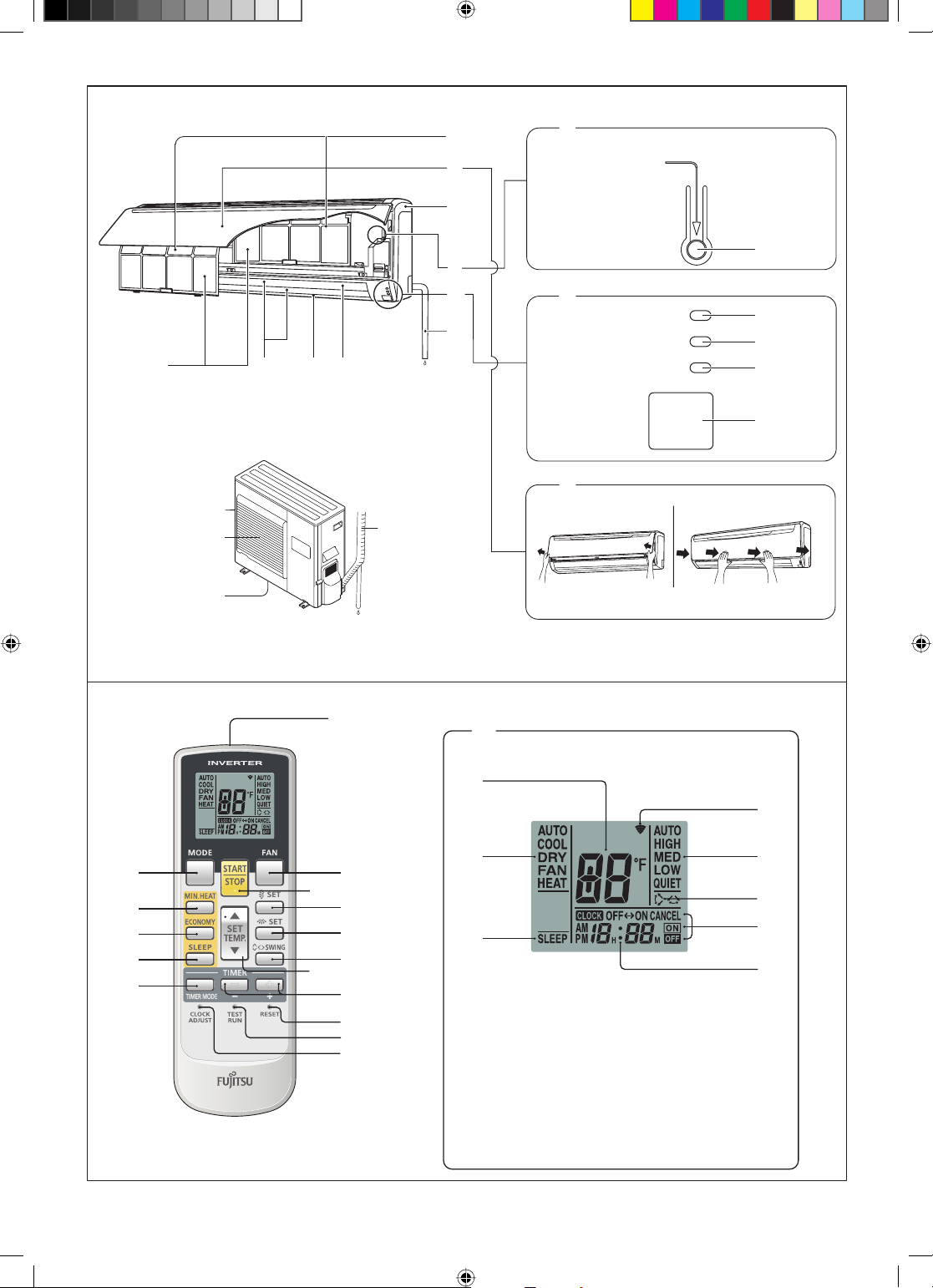
Fig. 1
a15
a8
a9
a1
ᒝ⥄േ
MANUAL
AUTO
Fig. 5
Fig. 6
a10
a16
a17
a19
a11
a12 a13
b1
a18
a1
a3
a14
c1
Fig. 2
a3
Fig. 3
a8
Fig. 4
OPERATION
TIMER
ECONOMY
a2
a5
a6
a7
a4
En-3
b2
b3
b4
b5
b6
b8
b12
b7
b9
b10
b11
b13
b16
b15
b14
c2
c5
c3
c6
c7
c4
c8
c9
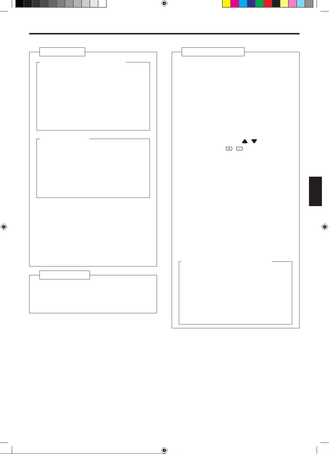
Fig. 7
To facilitate explanation, the accompanying illustration
has been drawn to show all possible indicators; in actual operation, however, the display will only show those
indicators appropriate to the current operation.
9315345271_OM.indb 39315345271_OM.indb 3 2/10/2010 9:55:36 AM2/10/2010 9:55:36 AM
NAME OF PARTS
Fig. 1 Indoor Unit
a1 Operating Control Panel (Fig. 2)
a2 MANUAL AUTO button
When kept on pressing the MANUAL AUTO
●
button for more than 10 seconds, the forced
cooling operation will start.
●
The forced cooling operation is used at the
time of installation.
Only for authorized service personnel's use.
When the forced cooling operation starts by
●
any chance, press the START/STOP button
to stop the operation.
a3 Indicator (Fig. 3)
a4 Remote Control Signal Receiver
a5 OPERATION Indicator Lamp (green)
a6 TIMER Indicator Lamp (orange)
If the TIMER indicator lamp flashes when
●
the timer is operating, it indicates that a fault
has occurred with the timer setting (See
Page 16 Auto Restart).
a7 ECONOMY Indicator Lamp (green)
a8 INTAKE GRILLE (Fig.4)
a9 Front Panel
a10 Air Filter
a11 Airfl ow Direction Louver
a12 Power Diffuser
a13 Right-Left Louver
(behind Airfl ow Direction Louver)
a14 Drain Hose
a15 Air Cleaning Filter
Fig. 5 Outdoor Unit
a16 Intake Port
a17 Outlet Port
a18 Pipe Unit
a19 Drain port (bottom)
Fig. 6 Remote Controller
b1 Signal Transmitter
b2 MODE button
b3 MIN.HEAT button
b4 ECONOMY button
b5 SLEEP button
b6 TIMER MODE button
b7 FAN button
b8 START/STOP button
b9 SET button (Vertical)
b10 SET button (Horizontal)
b11 SWING button
b12 SET TEMP. button (
/
)
b13 TIMER SET ( / ) button
b14 CLOCK ADJUST button
b15 TEST RUN button
This button is used when installing the air
●
conditioner, and should not be used under
normal conditions, as it will cause the indoor
unit’s thermostat function to operate incorrectly.
If this button is pressed during normal op-
●
eration, the indoor unit will switch to test operation mode, and the Indoor Unit’s OPERATION Indicator Lamp and TIMER Indicator
Lamp will begin to fl ash simultaneously.
To stop the test operation mode, press the
●
START/STOP button to stop the air
tioner.
b16 RESET button
c1 Remote Controller Display(Fig.7)
c2 Temperature SET Display
c3 Operation Mode Display
c4 SLEEP TIMER Display
c5 Transmit Indicator
c6 Fan Speed Display
c7 SWING Display
c8 T imer Mode Display
c9 Clock Display
condi-
En-4
9315345271_OM.indb 49315345271_OM.indb 4 2/10/2010 9:55:37 AM2/10/2010 9:55:37 AM
PREPARATION
Turn on the Power
Turn on the circuit breaker
1
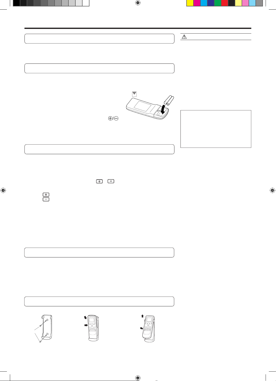
Load Batteries (AAA/R03/LR03 × 2)
Press and slide the battery compartment lid on the
1
reverse side to open it.
Slide in the direction of the arrow while pressing the mark.
Insert batteries.
2
Be sure to align the battery polarities ( ) correctly.
Close the battery compartment lid.
3
Set the Current time
Press the CLOCK ADJUST button (Fig. 6 b14).
1
Use the tip of a ball-point pen or other small object to press the button.
CAUTION!
Take care to prevent infants from acciden-
●
tally swallowing batteries.
When not using the Remote Controller for
●
an extended period, remove the batteries to
avoid possible leakage and damage to the
unit.
If leaking battery fl uid comes in contact with
●
your skin, eyes, or mouth, immediately wash
with copious amounts of water, and consult
your physician.
Dead batteries should be removed imme-
●
diately and disposed of properly, either in a
battery collection receptacle or to the appropriate authority.
Do not attem pt to recharge dry batteries.
●
Never mix new and used batteries, or batteries of different types.
Batteries should last about one year under normal use. If the Remote Controller’s
operating range becomes appreciably
reduced, replace the batteries and press
the RESET button with the tip of a ballpoint pen or other small object.
Use the TIMER SET ( / ) buttons (Fig. 6 b13) to
2
adjust the clock to the current time.
button: Press to advance the time.
(Each time the buttons are pressed, the time will be advanced/reversed
3
This completes the time setting and starts the clock.
button: Press to reverse the time.
in one-minute increments; hold the buttons depressed to change the time
quickly in ten-minute increments.)
Press the CLOCK ADJUST button (Fig. 6 b14) again.
To Use the Remote Controller
The Remote Controller must be pointed at signal receiver (Fig.3 a4) to operate correctly.
●
Operating Range: About 23ft (7 meters).
●
When a signal is properly received by the air conditioner, a beeping sound will be
●
heard.
If no beep is heard, press the Remote Controller button again.
●
Remote Controller Holder
Insert
Press in
Screws
Slide up
Pull out
Mount the Holder.2 Set the Remote Controller.
1
To remove the Remote Con-
3
troller (when use at hand).
En-5
9315345271_OM.indb 59315345271_OM.indb 5 2/10/2010 9:55:38 AM2/10/2010 9:55:38 AM
 Loading...