

Datasheet XFPN-03PGV, XFPN-03PGVR, XFGN-603PGVSR, XFPN-100KPGV, XFPN-100KPGVR Datasheet (Fujikura)
...
Features
.
Volt level output
.
On-chip amplification and temperature compensations
.
Pre-calibration of offset voltage and span
.
Surface mount package (XFGN)
Applications
.
Non-Invasive Blood Pressure(NIBP)monitor for home health care
.
Vacuum cleaner
.
Washing machine
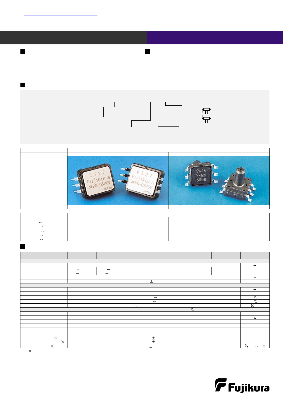
Part number for ordering
XFGN - 6 025KP G S R
Pressure type Gauge pressure
Model
XFPN XFGN-6
Package configuration Dual-In-line-Package (DIP) Surface mountpackage,6mm pressure port
Measurable pressure range (kPa)
Part number for ordering
0 24.5 XFPN-03PGV XFPN-03PGVR XFGN-603PGVSR
0 100 XFPN-100KPGV XFPN-100KPGVR XFGN-6100KPGVSR
0 25 XFPN-025KPG XFPN-025KPGR XFGN-6025KPGSR
0 50 XFPN-050KPG XFPN-050KPGR XFGN-6050KPGSR
0 100 XFPN-100KPG XFPN-100KPGR XFGN-6100KPGSR
0 200 XFPN-200KPG XFPN-200KPGR XFGN-6200KPGSR
Model/Rated pressure 03PGV 100KPGV 025KPG 050KPG 100KPG 200KPG Unit
Recommended operating conditions
Pressure type Gauge pressure
Rated pressure
24.5 100 25 50 100 200 kPa
0.250 1.020 0.255 1.020 1.020 2.040 kg/cm
2
Pressure media Non-corrosive gas
Excitation voltage 50.25 VDC
Absolute maximum rating
Maximum load pressure Twice of rated pressure
Maximum excitation voltage 8VDC
Operating temperature 10 80
Storage temperature 20 100
Operating humidity 30 80 (No dew condensation) RH
Electric performances/characteristics (Excitation voltage Vcc=5.0V constant, Ambient temperature Ta=25 )
Current consumption less than 10 mA
Output impedance lessthan 10
Source current lessthan 0.2 mA
Sink current less than 2 mA
Mechanical response time 2 (For the reference) msec
Full scale span voltage 4.0 V
Offset voltage
0.5 0.1 V
Full scale span voltage 4.5 0.1 V
Accuracy 5.0 FS/0 50
Note;Excluding input voltageerror.
Pre-amplified/5V Excitation/Gauge
XFPN,XFGN-6 Data sheet
Terminal leads direction (See Outline Diagram)
No mark :
R:
Rated pressure (Pa)
Model
XFPN
XFGN
Length of thepressure
port
(XFGN only)
6:6mm
Terminal leads configuration
No mark : DIP (XFPN)
S : Surfacemount package (XFGN)
Pressure type
G :Gauge (Positive pressure)
GV :Gauge (Negative pressure)
Specifications
1
查询XFGN-6050KPGSR供应商
0.5
12
14
15.24(600mil)
max 15
2.54 2.54
2.8
6.8
60
1.2
0.5
6
5
4
1
2
3
6
5
4
1
2
3
0.8
4.5
0.6
48
2.2
R1.5
0.25
3
C0.5
Labelled faceplate
Terminal leads
Pressure port
Vent hole
15.2
2.542.54
6- 0.9(Diameter of through holes)
6- 1.8(Diameter of lands)
0.5
12
6
5
4
14
48
2.2
R1.5
C0.5
15.24(600mil)
max 15
0.25
3
1
2
3
4.5
2.54 2.54
2.8
6.8
1.2
0.5
6
5
4
1
2
3
60
0.8
0.6
Labelled faceplate
Terminal leads
Pressure port
Vent hole
15.2
2.542.54
6- 0.9(Diameter of through holes)
6- 1.8(Diameter of lands)
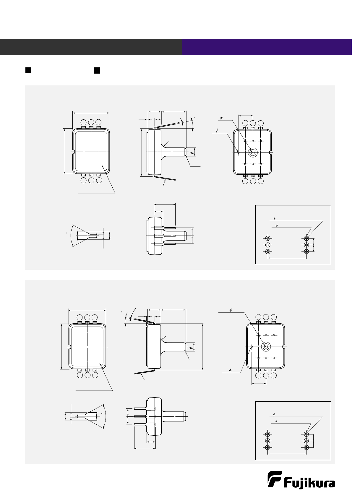
XFPN
Unit:mm
Recommended footprint for PCB
(Unit : mm)
XFPN-R
Unit:mm
Recommended footprint for PCB
(Unit : mm)
Pre-amplified/5V Excitation/Gauge
XFPN,XFGN-6 Data sheet
Outline dimensions
2

2.54 2.54
0.8
7
7
0.8
10.3
M
AX.
15
1
3
0.25
3.50.5
6
9.5
2-R0.5
123
123
654
654
Projections
Projections
Vent hole
Pressure port
Labelled faceplate
Index
2.542.54
6.0
1.4
2- 1(Holes for projections)
6.0
9.4
1.7
Land-pads
Vout
C1
C2
GND
Vout
GND
Vcc
Vcc(DC5V)
-
10 0 10
0
1
2
3
4
5
6
20 30 40 50 60 70 80
Temperature
Temperature Error Multiplier
Vout=Vs (P + ) (Pressure Error Temperature Error Multiplier Vs)
Vs=5.0volts
Notes ; The output voltage (Vout) is no perfect ratiometric with the power supply voltage.
P=Input Pressure(kPa)
Temperature Error Multiplier
Note ; Pleaseread instruction“Notes” before using the sensor.
Fujikura reserves the right to change specifications without notice.
If you haveany questions regarding technical issues or specifications,please contact us.
Sensor Engineering Department 5-1 Kiba 1-chome, Koto-ku, Tokyo135-8512, Japan
Phone +81-(0)3-5606-1072 Fax. +81-(0)3-5606-1538
E-mail : sensor@fujikura.co.jp
XFPN-6
Unit:mm
Recommended footprint for PCB
(Unit : mm)
XFPN, XFGN-6
Pre-amplified/5V Excitation/Gauge
XFPN,XFGN-6 Data sheet
Model pressure range Pressure Error(kPa)
03PGV 0 24.5kPa 0.03266 0.1 0.612
025KPG 0 25kPa 0.032 0.1 0.625
050KPG 0 50kPa 0.016 0.1 1.25
100KPG 0 100kPa 0.008 0.1 2.5
100KPGV 0 100kPa 0.008 0.1 2.5
200KPG 0 200kPa 0.004 0.1 5.0
Outline dimensions
Connection diagram
Remarks :
1) C1 : Connect 680pF capacitorwithin 2cmdistance from
leads.
2)C2 :Connect 0.01 F or more capacitor within 2cm dis-
tance from leads.
3)4 and 5 pins must be No Connection. Open them as floating ones completely, and do NOT connect to other line or
each other.
Transfer Function
3
 Loading...