


DIGITAL CAMERA
FinePix S3Pro
SERVICE MANUAL
US/CA/EU/EG/GE/AS/JP-Model
WARNING
THE COMPONENTS IDENTIFIED BY THE MARK “ ” ON THE SCHEMATIC
DIAGRAM AND IN THE PARTS LIST ARE CRITICAL FOR SAFETY.
PLEASE REPLACE ONLY BY THE COMPONENTS SPECIFIED ON THE SCHEMATIC
DIAGRAM AND IN THE PARTS LIST.
IF YOU USE PARTS NOT SPECIFIED, IT MAY RESULT IN A FIRE AND AN
ELECTRICAL SHOCK.
FUJI PHOTO FILM CO., LTD.
Ref.No.: ZM00576-102
Printed in Japan 2004.12

FinePix S3Pro Service Manual
SAFETY CHECK-OUT
After correcting the original problem, perform the following
safety check before return the product to the customer.
1. Check the area of your repair for unsoldered or poorly
soldered connections. Check the entire board surface
for solder splasher and bridges.
2. Check the interboard wiring to ensure that no wires are
“pinched” or contact high-wattage resistors.
3. Look for unauthorized replacement parts, particularly
transistors, that were installed during a previous repair.
Point them out to the customer and recommend their
replacement.
4. Look for parts which, though functioning, show obvious
signs of deterioration. Point them out to the customer
and recommend their replacement.
5. Check the B + voltage to see it is at the values
specified.
6. Make leakage - current measurements to determine
that exposed parts are acceptably insulated from the
supply circuit before returning the product to the
customer.
7. CAUTION: FOR CONTINUED
PROTECTION AGAINST FIRE
HAZARD, REPLACE ONLY WITH
SAME TYPE 2.5 AMPERES 125V
FUSE.
2.5A 125V
2.5A 125V
8. WARNING:
RISK OF FIREREPLACE FUSE
AS MARKED
ATTENTION: AFIN D'ASSURER
UNE PROTECTION
PERMANENTE CONTRE LES
RISQUES D'INCENDIE,
REMPLACER UNIQUEMENT
PAR UN FUSIBLE DE MEME,
TYPE 2.5 AMPERES, 125 VOLTS.
TO REDUCE THE ELECTRIC
SHOCK, BE CAREFUL TO
TOUCH THE PARTS.
WARNING!
HIGH VOLTAGE
2

FinePix S3Pro Service Manual
TABLE OF CONTENTS
TABLE CONTENTS
1. General ........................................................... 4
1-1. Product specification .............................................. 4
1-2. Explanation of Terms .............................................. 7
1-3. Names of External Components ............................ 8
2. Disassembly ................................................. 11
2-1. Names of internal Components ............................ 11
2-2. Removing the BATT CART ASSY ........................ 12
2-3. Removing the R CABI ASSY ................................ 12
2-4. Removing the SW PWB ASSY ............................. 13
2-5. Removing the LCD ............................................... 15
2-6. Removing the 10-pin TERMINAL ASSY ............... 15
2-7. Removing the BATTERY HOLDER ...................... 15
2-8. Removing the MAIN PWB ASSY .......................... 16
Removing the CCD PWB ASSY and CCD UNIT
2-9.
2-10. How to dismantle the parts around the outer
wrappings ............................................................. 19
2-10-1. Removing TOP COVER UNIT ................ 19
2-10-2. Removing SB LOWER CASE UNIT ....... 21
...... 17
3. Schematic ..................................................... 23
3-1. Cautions ............................................................... 23
3-2. Basic block name and function explanation ......... 23
3-3. Description of the Main Block Functions .............. 23
3-3-1. Overview of the new technology .............23
3-3-2. Block function descriptions ..................... 24
3-3-3. Description of the Power Supply Block
Functions ................................................ 24
3-4. Block Diagram ...................................................... 25
3-5. Overall connection Diagram ................................. 26
3-6. Circuit Diagrams ...................................................27
3-6-1. CCD BLOCK ........................................... 27
3-6-2. DCDC BLOCK ........................................ 28
3-6-3. IEEE1394 BLOCK .................................. 29
3-6-4. PROCESS BLOCK .................................30
3-6-5. CARD BLOCK ........................................ 31
3-6-6. DCDC BLOCK (CAMERA BODY) .......... 31
3-6-7. PARTNER-CHIP BLOCK ........................32
3-6-8. PWON BLOCK ....................................... 33
3-6-9. USB2.0 BLOCK ...................................... 34
3-6-10. LCD BLOCK ........................................... 35
3-6-11. SW BLOCK .............................................36
3-7. Mounted Parts Diagrams ...................................... 37
3-7-1. CCD PWB ASSY .................................... 37
3-7-2. MAIN PWB ASSY ...................................38
3-7-3. SW PWB ASSY ...................................... 40
4. Adjustments .................................................. 41
4-1. Important point Adjustment when
Replacing Major Parts ..........................................41
4-2. Measuring Instruments Used ............................... 41
4-3. Use Jig list ............................................................ 41
4-4. Calibration method of pattern box ........................ 43
4-5. Adjusting soft installation ......................................43
4-5-1. Various downloading software
decompressions, preservation methods,
and notes ................................................43
4-5-2. Installation of DSC jig driver ................... 44
4-5-3. Adjusting soft initiation method ...............44
4-6. Initial Settings of the Adjustment Software ........... 45
4-7. Starting the Adjustment Software ......................... 48
4-8. [F4] : CCD Defect Correction ............................... 51
4-9. [F5] : CAMERA Adjustment ..................................53
4-10. [F1] : Battery Voltage Adjustment .........................56
4-11. [F11] : Video Adjustment ...................................... 60
4-12. [F2] : Rear LCD Panel Adjustment ....................... 62
4-13. [F8] : Firmware Download .................................... 64
4-14. [F12] : End Setting................................................ 66
5. Inspection ..................................................... 71
5-1. Measuring Instruments and Jigs Used for
Inspection .............................................................71
5-2. Connection of Measuring Instruments for
Inspection .............................................................71
5-3. Inspection and Settings at Shipment ....................72
5-4. Resolution Checking ............................................ 76
5-5. CCD Cleaning and Inspection Procedures ........... 78
5-5-1. CCD Cleaning Using a
Visual Inspection for Dusting .................. 78
5-5-2. CCD Cleaning Using
Test Photography to Detect Dusting ....... 79
5-6. AF Checking .........................................................80
5-6-1. Measuring equipment and tools
used for AF checking ..............................80
5-6-2.
5-6-3. AF testing procedure .............................. 81
5-6-4. Cause identification procedure for
Settings for the measuring equipment
and tools used for AF checking ..................
focus-related problems ........................... 82
80
6. Parts List....................................................... 83
6-1. Packing and Accessories ..................................... 83
6-1-1. US-model ................................................ 83
6-1-2. CA-model ................................................ 84
6-1-3. EU-model ................................................ 85
6-1-4. EG-model ................................................ 86
6-1-5. GE-model ................................................ 87
6-1-6. AS-model ................................................88
6-1-7. JP-model ................................................. 89
6-2. Transportable form and necessary parts for
camera body repair .............................................. 90
6-3. CAMERA BODY ................................................... 91
6-4. R CABI ................................................................. 92
6-5. Internal parts ........................................................ 93
6-5-1. US/CA-model .......................................... 93
6-5-2. EU/EG/GE/AS-model .............................. 94
6-5-3. JP-model ................................................. 95
6-6. List of parts related to exterior .............................. 96
6-6-1. TOP COVER 1 ........................................ 96
6-6-2. TOP COVER 2 ........................................ 97
6-6-3. TOP COVER 3 ........................................ 98
6-6-4. CAMERA BODY External ....................... 99
6-7. Electrical parts ....................................................100
7. Appendix..................................................... 101
7-1. List of Related Technical Updates Issued .......... 101
3

1. General
FinePix S3Pro Service Manual
1. General
1-1. Product specification
System
Model Digital camera FinePix S3 Pro
Effective pixels 12.34 million (S-pixel: 6.17 million, R-pixel: 6.17 million) pixels
CCD Large-format (23.0
Total 12.9 megapixels (S-pixels: 6.45 million; R-pixels: 6.45 million)
Storage media xD-Picture Card (16/32/64/128/256/512 MB)
CF card and Microdrive TM (FAT32-compatible) (Compatibility is listed on Fujifilm website:
http://home.fujifilm.com/products/digital/)
File format DCF-compliant
Compressed: Exif Ver.2.21 JPEG, DPOF-compatible
Uncompressed: CCD-RAW (RAF)*1
Max. recording resolution 4256
Number of recorded pixels 4256
Lens mount Nikon F mount (with AF coupling and AF contacts)
Focal length Approx. 1.5
Sensitivity ISO 100/160/200/400/800/1600 *2
Metering modes TTL open metering/3D 10-zone Matrix, Center-weighted, Spot
Exposure control Program AE, Shutter-priority AE, Aperture-priority AE, Manual exposure
Exposure compensation -3.0 EV to +3.0 EV 1/2 EV step
Shutter Electronically controlled vertical-travel focal-plane shutter
Shutter speeds 30 to 1/4000 sec, Bulb X contact: Max. 1/180 sec. *3
Continuous shooting Max. 2.5 frames/sec.:
Auto bracketing ±0.5 EV, ±1.0 EV, ±1.5 EV, ±2.0 EV,
Focus Mode: Single-AF servo, Continuous AF servo, Manual
White balance Automatic scene recognition/Preset (Fine, Shade, Fluorescent (Daylight), Fluorescent
Self-timer 20 sec./10 sec./5 sec./2 sec.
Flash Manual pop-up, D-3D Multi-BL flash control, D Multi-BL flash control, Standard D-TTL
Flash modes Front Synchro, Slow Synchro, Rear synchro, Red-eye Reduction and Red-eye Reduction
Accessory shoe Standard ISO-type with hot-shoe contact (Safty lock provided)
Synchro contacts X contacts only, synchronizing speed: 1/180 sec. or slower
Synchro terminal Equipped with ISO 519 synchro terminal as standard, lock screw provided
Viewfinder Eye-level pentaprism (coverage: Approx. 93% vertical, approx. 95% horizontal), dioptric
LCD monitor 2.0-inch 235,000-pixels low-temperature polysilicon TFT color LCD panel (approx. 100%
Remote release Release socket built into the shutter release button
Photography functions
Playback functions Trimming, Auto Play, multi-frame playback, histogram display, brightness warning display
Other functions PictBridge compatibility, Exif Print compatibility, PRINT Image Matching II compatibility,
×
2848 (12.1 million)
×
2848 pixels/3024 × 2016 pixels/2304 × 1536 pixels/1440 × 960 pixels
×
Max. 1 frame/sec.:
Max. 1.4 frames/sec.: Up to max. 3 frames. (D-range: Wide; RAW mode)
AF system: TTL phase difference detection with auxiliary AF flash
AF frame selection: Single-area AF, Dynamic AF (Dynamic AF Mode with Closest Subject
Priority is available)
(Warm White), Fluorescent (Cool White), Incandescent, Custom (2 settings)
flash control
Guide No.: 12 (ISO 100-m); Sync. shutter speed: 1/180 sec. or slower
Slow Synchro, suppressed flash
adjustment mechanism, viewfinder magnification approx. 0.8
coverage for playback)
10-pin remote release terminal provided on camera body front
Color space selection, dynamic range selection, film simulation mode selection, framing
guideline, frame no. memory, multiple-exposure shooting, shutter button for vertical
shooting, live image
language selection (Japanese, English, French, German, Spanish, Italian, Chinese),
discharging function
×
15.5 mm) Super CCD SR II with primary color filter
the nominal focal length of the lens (35mm camera equivalent)
Up to max. 12 frames. (D-range: Standard; JPEG mode)
Up to max. 7 frames. (D-range: Standard; RAW mode)
Up to max. 6 frames. (D-range: Wide; JPEG mode)
×
)
4

FinePix S3Pro Service Manual
Power Supply and Others
Power supply Use one of the following:
• 4× AA-size Ni-MH (Nickel-Metal Hydride) batteries
• AC Power Adapter AC-5VX (sold separately)
Dimensions and weight
(W × H × D)
Operating conditions Temperature: 0
Guide to the number
of available frames
for battery operation
Accessories z AA-size Ni-MH Batteries (HR-AA) (4)
Optional accessories z xD-Picture Card
Camera body dimensions: 147.8 mm × 135.3 mm × 78.5 mm/5.8 in. × 5.3 in. × 3.1 in.
(excluding lens and attachments)
Camera body weight: 815 g/28.7 oz (excluding lens, batteries and recording media)
Weight when shooting: Dependent on the lens used
*Note that the range for Microdrive is +5
Humidity: 80% or less (no condensation)
o
C to +40oC. (+32oF to +104oF)
Battery Type With LCD monitor ON
Ni-MH batteries 2300 mAh Approx. 400 frames
According to the CIPA (Camera & Imaging Products Association) standard procedure for
measuring digital still camera battery consumption (extract):
When using Ni-MH batteries, use the batteries supplied with the camera. The storage
media should be xD-Picture Card.
Shots taken at 23
AF operation, full flash for every other shot, the camera turned off/on every 10 shots and
auxiliary AF lighting turned off.
• Note: Because the number of available shots varies depending on the level of charge in
Ni-MH batteries, the figures shown here for the number of available shots using
batteries are not guaranteed.
The number of available shots will also decline at low temperatures.
z Battery charger BCH-NH2 (1)
*
Plug-in and cord-attached types are provided depending on the intended country of use.
z Strap (1) z Accessory shoe cover (1) Fitted on the camera body
z Eyepiece cap (1) z LCD cover (1) Fitted on the camera body
z Camera body cap (1) Fitted on the camera body
Video cable (1) (approx. 1.5 m (4.9ft.), mini-plug (3.5 mm-dia.) to pin-plug cable)
z
z IEEE 1394 4-pin to 6-pin cable (1) (approx. 1.5 m (4.9ft.))
z USB cable (mini-B) (1) z Cable holder (1) z Clamp filter (1)
z Synchronizing terminal cap (1) Fitted on the camera body
z Remote release socket cap (1) Fitted on the camera body
z Battery holder (1) Fitted on the camera body
z CD-ROM: Software for FinePix AX (1)
z Owner’s Manua (1) z Software Quick Start Guide (1)
DPC-16 (16 MB)/DPC-32 (32 MB)/DPC-64 (64 MB)/DPC-128 (128 MB)/
DPC-256 (256 MB)/DPC-512 (512 MB)
z AC Power Adapter AC-5VX
z Fujifilm Rechargeable Battery 2HR-3UF
z Fujifilm Battery Charger with Battery BK-NH2 (With Euro type or UK type plug)
z Image Memory Card Reader DPC-R1
• Compatible with Windows 98/98 SE, Windows Me, Windows 2000 Professional,
Windows XP or iMac, Mac OS 8.6 to 9.2.2, Mac OS X (10.1.2 to 10.2.2) and
models that support USB as standard.
• Compatible with xD-Picture Card of 16 MB to 512 MB, and SmartMedia of 3.3 V,
4 MB to 128 MB.
z PC Card Adapter DPC-AD
• Compatible with xD-Picture Card of 16 MB to 512 MB, and SmartMedia of 3.3 V,
2 MB to 128 MB.
z CompactFlash Card Adapter DPC-CF
• Windows 95/98/98 SE/Me/2000 Professional/XP
• Mac OS 8.6 to 9.2/X (10.1.2 to 10.1.5)
z xD-Picture Card USB Drive DPC-UD1
• Compatible with xD-Picture Card of 16 MB to 512 MB
• Windows 98/98 SE/Me/2000 Professional/XP
• Mac OS 9.0 to 9.2/X (10.0.4 to 10.2.6)
z Hyper-Utility Software HS-V2 Ver.3.0
o
C, one shot every 30 seconds using a 50mm AF1.4D lens with 1-time
1. General
o
C to +40oC (+41oF to +104oF).
5

1. General
*1: CCD-RAW is a format specific to the FinePix S3 Pro. The enclosed “FinePixViewer” software or the optional
Hyper-Utility software “HS-V2 Ver. 3.0” is required to interpret the images.
*2: Images shot in high-sensitivity photography (ISO 400 or higher) may appear coarse and may also be affected
by noise such as white dots.
*3: Images shot with long exposures (about 4 second or longer) may appear coarse and may also be affected by
noise such as white dots.
FinePix S3Pro Service Manual
Input/Output Terminals
Video output NTSC/PAL selectable
Digtal Interface USB 2.0 (High-speed), IEEE 1394
DC input Socket for specified AC Power adapter AC-5VX (sold separately)
Standard Number of Available Shots per Media
The number of available shots varies slightly depending on the type of subject. Also, the discrepancy between the actual
number of available shots and the standard number grows as the capacity of the media increases.
Number of recorded
pixels
Quality Mode
Image File Size
DPC-16 (16 MB)
DPC-32 (32 MB)
DPC-64 (64 MB)
DPC-128 (128 MB)
DPC-256 (256 MB)
DPC-512 (512 MB)
Microdrive (340 MB)
Microdrive (1 GB)
CCD-RAW
HIGH
D-RANGE
WIDE
Approx.
25 MB
10 19
2039
13 27
41 81
D-RANGE
STANDARD
Approx.
13 MB
0 1
12
2 4
5 9
For CCD-RAW files, “ ” is displayed as the resolution.
4256 2848 1440 9603024 2016 2304 1536
FINE
Approx.
4.7 MB
107
220 437
NORMAL
Approx.
2.4 MB
3
6
13
26
53
73 146 116 232200 396 338 671
6
13
26
53
107
214
FINE
Approx.
3.0 MB
170
349 698 597 1173 9951932
10
21
42
85
5
NORMAL
Approx.
1.5 MB
10
20
42
84
169
339
FINE
Approx.
1.7 MB
8
17
36
72
146
292
NORMAL
Approx.
880 KB
17
35
72
144
290
580
FINE
Approx.
1 MB
14
30
61
122
245
491
NORMAL
Approx.
520 KB
29
59
120
241
484
967
6

FinePix S3Pro Service Manual
1. General
1-2. Explanation of Terms
Adobe RGB (1998) A color space introduced as the working color space for Adobe Photoshop 5.0.
AdobeRGB encompasses almost all the colors reproduced by CMYK printers and is
intended primarily for printing applications. It was introduced as “SMPTE-240E” in the
RGB settings in Adobe Photoshop 5.0 and as “Adobe RGB (1998)” in the profile settings
from version 6.0 onwards.
CCD-RAW This is the image data prior to signal processing (the reconstruction of the data read in
from the CCD as an image). Because the signal processing is performed on the computer, high levels of control are possible.
• To reconstruct images, FinePixViewer (on the enclosed CD-ROM) or the Hyper Utility
(optional) must be installed on your computer.
Color space Refers to the range of colors, expressed as two-dimensional or three-dimensional
numerical values, that can be reproduced by devices such as cameras, monitors and
printers. The sRGB and AdobeRGB color spaces are each shown as an xy color chart (a
coordinate color space in which colors are represented in two dimensions with no
brightness value). The range of colors that can be expressed by a particular color space
is indicated by a triangle imposed on the xy color chart. Colors become brighter as they
approach the outer edge of the xy color chart. This color representation method is
capable of showing all the actual colors.
Color Temperature Low-temperature light sources, such as a candle flame, are strongly red, while high-
temperature light sources, such as a gas burner flame, are strongly blue. The color of
the light for these temperatures is expressed as a color temperature (K = Kelvin). The
light of the sun at midday in a completely clear sky is taken to be 5500K.
EV: A number that denotes Exposure Value. The EV is determined by the brightness of the
subject and sensitivity (speed) of the film or CCD. The number is larger for bright
subjects and smaller for dark subjects. As the brightness of the subject changes, a
digital camera maintains the amount of light hitting the CCD at a constant level by
adjusting the aperture and shutter speed.
When the amount of light striking the CCD doubles, the EV increases by 1. Likewise,
when the light is halved, the EV decreases by 1.
JPEG: Joint Photographic Experts Group
A file format used for compressing and saving color images. The higher the compression
rate, the greater the loss of quality in the decompressed (restored) image.
White Balance: Whatever the kind of the light, the human eye adapts to it so that a white object still
looks white. On the other hand, devices such as digital cameras see a white subject as
white by first adjusting the color balance to suit the color of the ambient light around the
subject. This adjustment is called matching the white balance.
Exif Print: Exif Print Format is a newly revised digital camera file format that contains a variety of
shooting information for optimal printing.
7
1. General
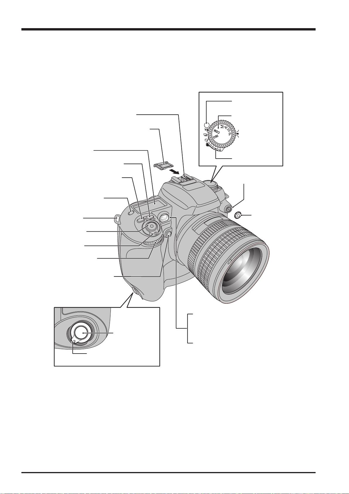
1-3. Names of External Components
Accessory shoe
Accessory shoe cover
Top display panel
Exposure compensation button
FinePix S3Pro Service Manual
Release mode switch
unlock button
Exposure mode dial
Release mode switch
Flash exposure compensation
button
LCD illuminator button
Strap mount
Shutter button
Power switch
Sub-command dial
Depth of field check button
Shutter button for
vertical shooting
Synchronizing terminal
Synchronizing
terminal cap
AF-assist illuminator
Self-timer lamp
Red-eye reduction lamp
Lock lever for vertical shooting
8
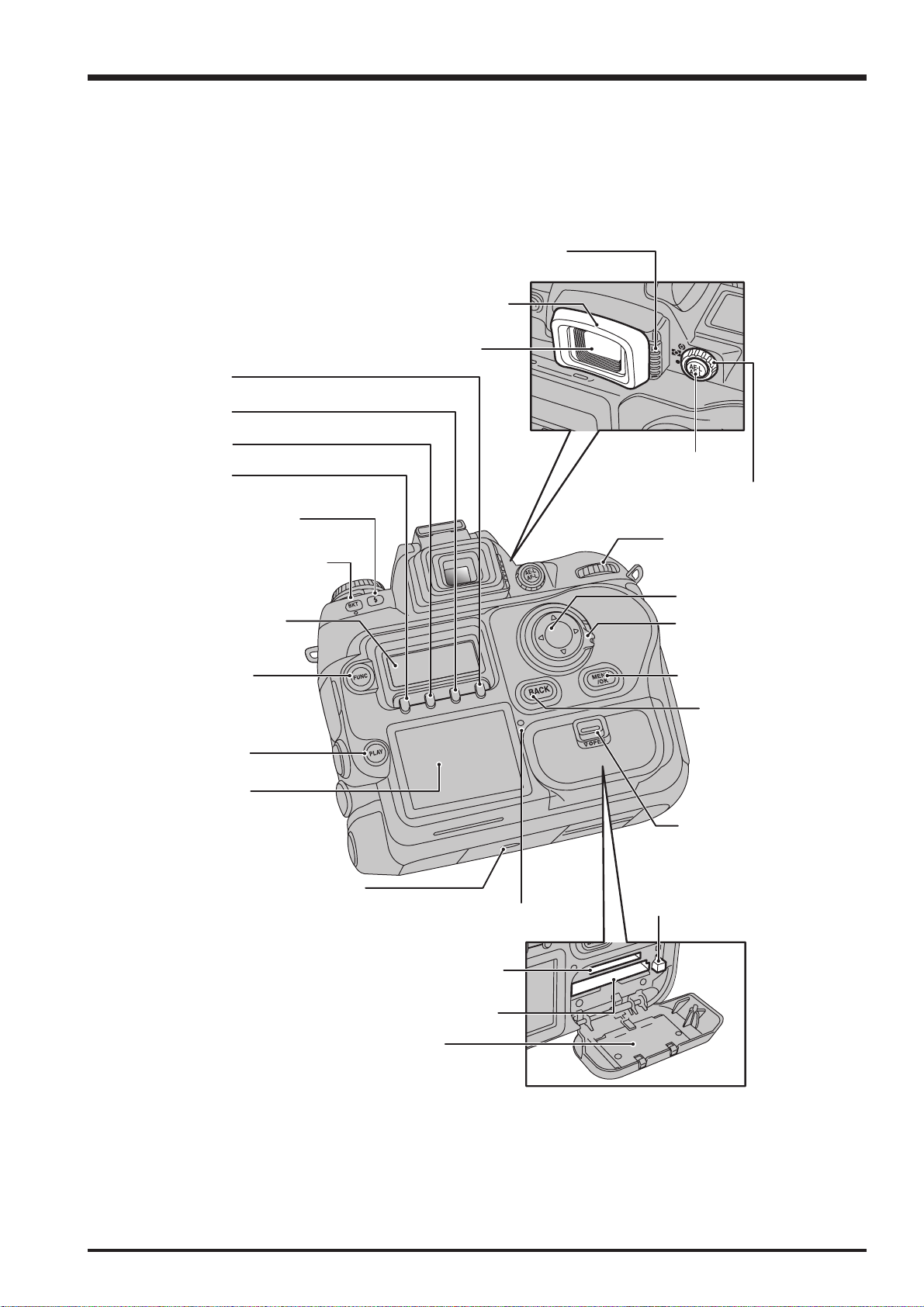
FinePix S3Pro Service Manual
A
F4 button
F3 button
F2 button
F1 button
1. General
Diopter adjustment knob
Rubber eyecup
Viewfinder
AE-L/AF-L button
Metering system selector dial
Synchro mode button
Main-command dial
uto Exposure Bracketing
button
4-direction button
Rear display panel
FUNC button
PLAY button
LCD monitor
Tripod mount
Access lamp
CF / Microdrive
eject button
4-direction button
lock switch
MENU/OK button
BACK button
Slot cover
unlock button
xD-Picture Card slot
CF / Microdrive slot
Slot cover
9
1. General
r
r
r
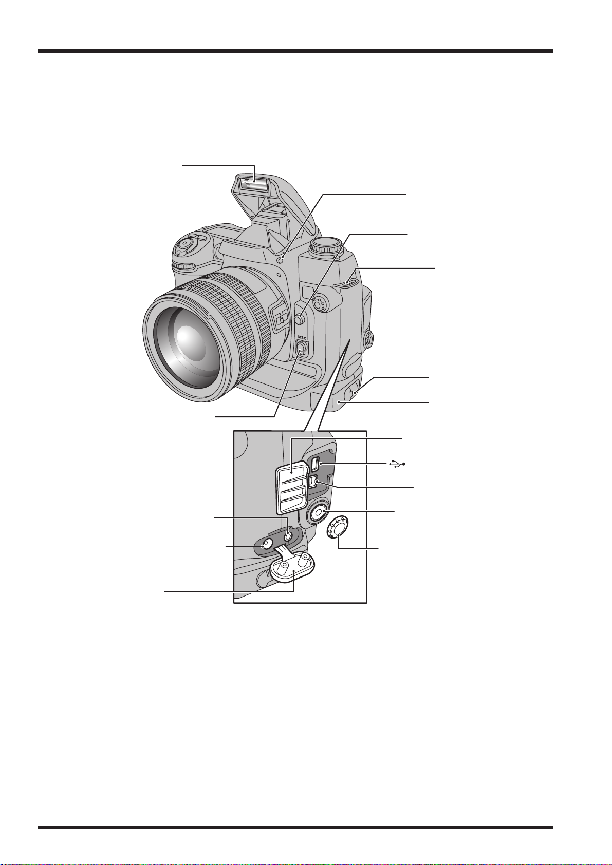
FinePix S3Pro Service Manual
Flash
Flash pop-up button
Lens release button
Strap mount
Focus mode selector switch
VIDEO OUT (Video output)
socket
DC IN 5V (power input) socket
Terminal cover
Battery holde
release catch
Battery holde
Digital terminal cove
USB socket (mini-B)
IEEE 1394 socket
Remote release socket
(10-pin terminal)
Remote release socket cap
10

FinePix S3Pro Service Manual
2. Disassembly
2-1. Names of internal Components
DOT MATRIX LCD
SW PWB ASSY
2. Disassembly
R CABI ASSY
REAR FRAME
CCD PWB ASSY
RELESE HOLDER CONST
CCD UNIT
LCD MONITOR
10Pin TERMINAL ASSY
MAIN PWB ASSY
BATT HOLDER
BOTTOM FRAME ASSY
CAMERA BODY ASSY
BATT CART ASSY
11

2. Disassembly
2-2. Removing the BATT CART ASSY
(1) Unlock the battery holder by turning the lock lever and
pull out the BATT CART ASSY.
FinePix S3Pro Service Manual
1
2-3. Removing the R CABI ASSY
(1) Open the CARD COVER.
(2) Open the DIGITAL TERMINAL COVER.
(3) Remove the 16 screws (N-MS2M 1.7 x 3.0 BA).
(4) Remove the R CABI ASSY in the direction of the arrow.
(5) Remove the MAIN-SW FPC from the connector (SW
PWB ASSY CN 102).
3
4
2
3
3
1
3
[Notes on assembling the R CABI ASSY]
1. Ensure that the FPC is not inserted on an angle and
that it is fully inserted before locking.
2. Confirm the IEEE1394 JACK is correctly matched to
the hole of R CABI ASSY.
3. Ensure that there are no gaps
between the CAMERA BODY
ASSY and R CABI ASSY after
assembly.
12
5
FinePix S3Pro Service Manual
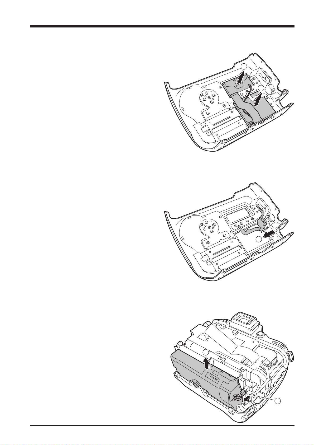
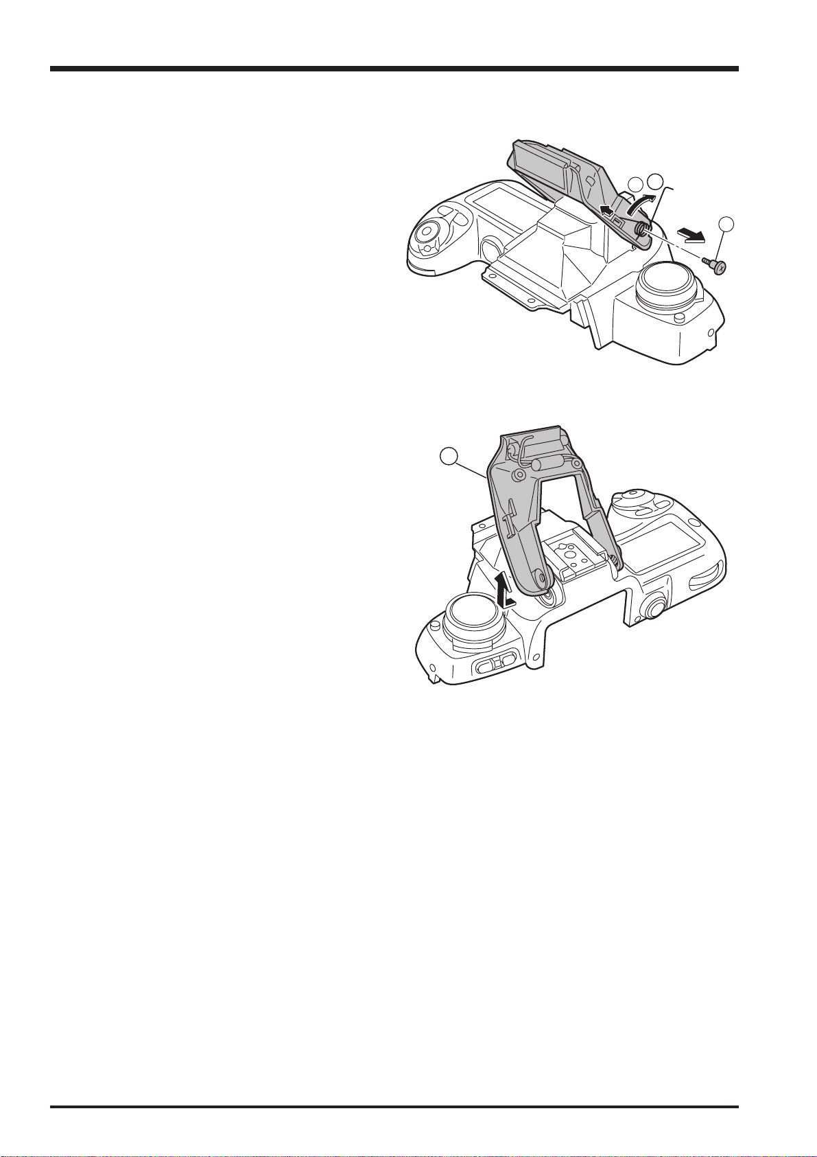
2-4. Removing the SW PWB ASSY
2. Disassembly
(1) Remove the FPC at 3 points.
(2) Remove the wire harness at 1 point.
(3) Remove the EMI SHEET 10 FPC in the direction of the
arrow.
1
2
3
(4) Remove the EMI SHEET 10 CNN in the direction of the
arrow.
4
13

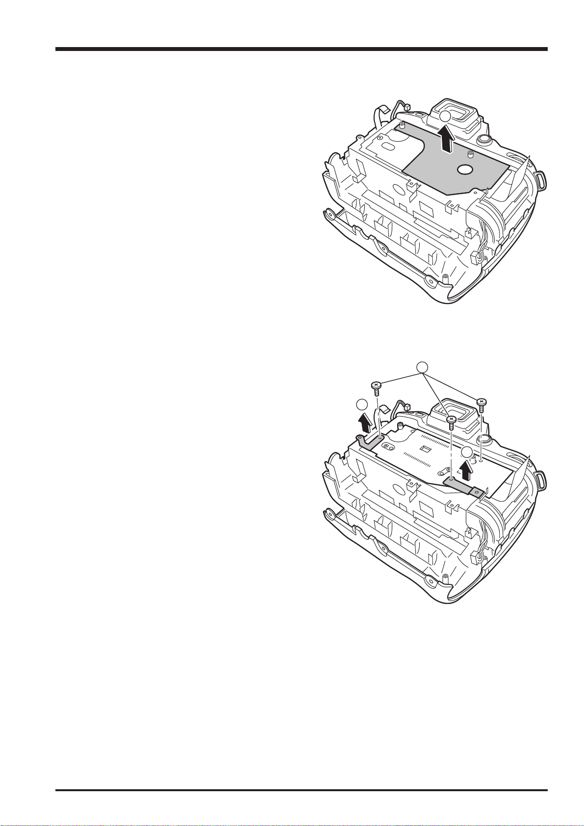
2. Disassembly
FinePix S3Pro Service Manual
(5) Remove the 3 screws (BT2M 1.7 x 4.0 B).
(6) Remove the REAR FRAME in the direction of the
arrow.
(7) Remove the SW PWB ASSY in the direction of the
arrow.
6
5
Hook
[Notes on assembling the SW PWB ASSY]
1. Check that the top edge of the SW PWB ASSY is
engaged with the hook on the R CABI ASSY side.
2. Take care to avoid inserting the FPC on an angle and
ensure that it is fully inserted before locking.
3. Ensure that there are no gaps between the CABI
after assembly.
7
14
FinePix S3Pro Service Manual
2-5. Removing the LCD
(1) Remove the DOT MATRIX LCD in the direction of the
arrow.
(2) Remove the LCD MONITOR in the direction of the
arrow.
2-6. Removing the 10-pin TERMINAL ASSY
2. Disassembly
1
2
(1) Remove the 10-pin TERMINAL ASSY in the direction of
the arrow.
2-7. Removing the BATTERY HOLDER
(1) Remove the wire harness from the connector (MAIN
PWB ASSY CN 600).
(2) Remove the BATTERY HOLDER in the direction of the
arrow.
1
2
1
15

2. Disassembly
2-8. Removing the MAIN PWB ASSY
(1) Remove the FPC from the connector (MAIN PWB
ASSY CN 101).
(2) Remove the 2 screws (BT2M 1.7 x 4.0 B).
(3) Remove the RELEASE HOLDER CONST in the
direction of the arrow.
FinePix S3Pro Service Manual
1
2
3
(4) Remove the wire harness (CAMERA BODY) from the
connector (MAIN PWB ASSY CN 700).
(5) Remove the MAIN-CCD FPC from the connector
(MAIN PWB ASSY CN 100).
(6) Remove the wire harness (CAMERA BODY) from the
connector (MAIN PWB ASSY CN 104).
(7) Remove the FPC (CAMERA BODY) from the connector
(MAIN PWB ASSY CN 103).
(8) Remove the 6 screws (MS2M 1.7 x 3.0 N).
(9) Remove the MAIN PWB ASSY in the direction of the
arrow.
8
7
8
6
8
5
4
[Notes on assembling the MAIN PWB ASSY]
Check that the notch in the CARD SLOT side of the
MAIN PWB ASSY is engaged with the hook on the
CAMERA BODY.
16
9
Hook
FinePix S3Pro Service Manual
2. Disassembly
2-9. Removing the CCD PWB ASSY and CCD UNIT
(1) Remove the SHIELD SHEET.
1
(2) Remove the 3 screws (CCD PWB SCREW).
(3) Remove the EMI SHEET L in the direction of the arrow.
(4) Remove the EMI SHEET R in the direction of the arrow.
2
3
4
17

2. Disassembly
FinePix S3Pro Service Manual
(5) Remove the solder on the CCD PWB ASSY (36
locations).
(6) Remove the CCD PWB ASSY in the direction of the
arrow.
(7) Remove the 4 screws (M 1.2 x 2.4 C).
(8) Remove the CCD UNIT in the direction of the arrow.
5
6
7
8
18
FinePix S3Pro Service Manual
2. Disassembly
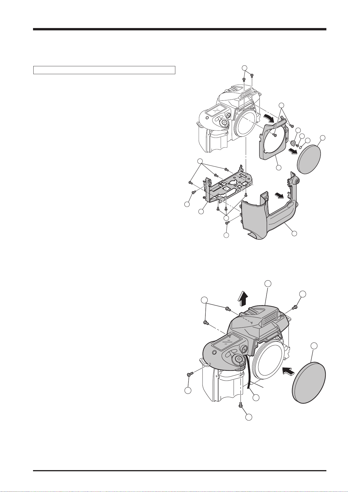
2-10. How to dismantle the parts around the outer wrappings
2-10-1. Removing TOP COVER UNIT
Revised: 1. Dec. 2004
Remove in the order indicated by circled numbers.
<Step 1>
(1) Remove the lens cap.
(2) Remove A/M COVER PLATE.
(3) Remove one screw.
(4) Remove A/M CHANGE LEVER.
(5) Remove two screws.
(6) Remove two screws.
(7) Remove four screws.
(8) Remove FRONT COVER BLACK in the direction of
the arrow.
(9) Remove FRONT CABINET UNIT in the direction of
the arrow.
(10) Remove four screws.
(11) Remove the MAIN FRAME.
6
5
4
3
7
8
10
11
10
7
9
1
2
<Step 2>
(12) Do the lens cap.
(13) Remove five screws.
(14) Float TOP COVER UNIT in the direction of the arrow.
(15) Remove one screw.
13
14
13
13
12
Black:
15
13
19
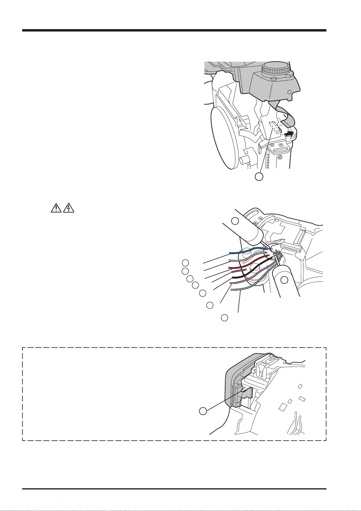
2. Disassembly
<Step 3>
(16) Remove FPC from the TOP COVER side, and
remove TOP COVER UNIT to the grip side.
* As for the grip side, the harness is stopped with solder.
FinePix S3Pro Service Manual
Revised: 1. Dec. 2004
16
<Step 4>
(17) Peel off the insulation tape then discharge the MAIN
CONDENSER before remove the wiring harnesses.
(18) Remove six harness, and remove TOP COVER
UNIT completely.
[ Notes of assembly of TOP COVER UNIT ]
Hang part A inner EYE PIECE BARREL UNIT.
And, build in TOP COVER UNIT.
18
18
Blue:
White:
18
18
Red:
Brown:
18
Black:
18
Pink:
Light Blue:
18
17
17
20
A

FinePix S3Pro Service Manual
2. Disassembly
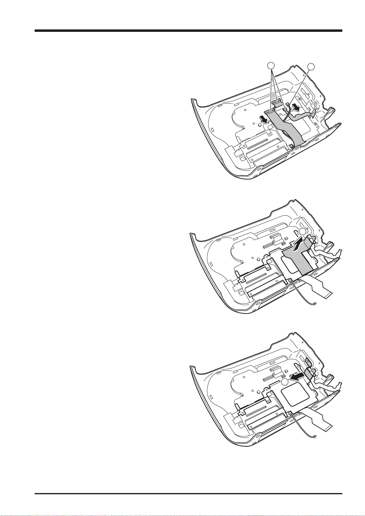
2-10-2. Removing SB LOWER CASE UNIT
Remove in the order indicated by circled numbers.
<Step 1>
(1) Remove two screws.
(2) Remove the hook in two places.
<Step 2>
(3) Remove two screws.
(4) Float TOP COVER FPC.
Revised: 1. Dec. 2004
1
2
3
3
<Step 3>
(5) Pull out the harness of the flash in the direction of the
arrow after floating TOP COVER FPC.
3
4
5
21
2. Disassembly
<Step 4>
(6) Remove FLASH UP SPRING in the direction of A.
(7) Remove one screws.
<Step 5>
(8) Remove SB LOWER CASE UNIT in the direction of
the arrow.
FinePix S3Pro Service Manual
Revised: 1. Dec. 2004
A
6
7
8
22

FinePix S3Pro Service Manual
3. Schematics
3. Schematic
3-1. Cautions
<Caution when replaceing chip (leadless) parts>
• Do not re-use the removed parts, but use new parts. Be careful that the negativ side of the tantalum capacitors are
susceptible to heat.
• Voltage indications are omitted for capacitors other than chemical and tantalum capacitors with a dielectric strength of 50
V or less.All units are uF (p shows pF).
• Chip resistors without indication are 1/10 W.
•KΩ = 1000Ω, MΩ = 1000KΩ
• Variable resistors and semi-variable resistor are abbreviated the specification of B characteristic.
3-2. Basic block name and function explanation
Part name Block name Function
CCD UNIT CCD BLOCK CCD output (IC900)
CCD PWB ASSY CCD BLOCK CCD driver (IC901, 902), Analog to digital conversion of CCD
output (IC906)
MAIN PWB ASSY PROCESS BLOCK Video signal processing, System control, SW detection
management (IC104), SDRAM (IC101, 102, 103, 106),
FLASH ROM (IC112)
DCDC BLOCK Power supply management (IC600)
PWON BLOCK POWER ON control (IC204, 205)
PARTNER-CHIP BLOCK Video signal processing assistance (IC1100)
IEEE1394 BLOCK IEEE1394 communication (IC304)
USB2.0 BLOCK USB2.0 communication (IC400)
CARD BLOCK xD card slot (CN800), CF TypeII slot (CN801)
DCDC BLOCK (CAMERA BODY)
SW PWB ASSY LCD BLOCK LCD control (IC500)
SW BLOCK Operation SW
Power supply to CAMERA BODY (IC707)
3-3. Description of the Main Block Functions
3-3-1. Overview of the new technology
A number of technological innovations have been used on this model. These innovations are described below.
(1) Large-format (15.5 x 23.0 mm) “Super CCD Honeycom SRII” featuring a new structural design
• Ultra-high image quality with a maximum recorded image size of 4256 x 2848 pixels (12.1 megapixels) provided by the
“Honeycom Signal Processing System” and a resolution of 12.34 effective megapixels (high-sensitivity S pixels: 6.17
million; R pixels designed to increase dynamic range: 6.17 million).
• The “Super CCD Honeycom SRII” is a newly designed CCD that increases the dynamic range to roughly 4 times that of
the previous FinePix S2Pro and provides rich and detailed tonal gradations. It provides superb image quality featuring
high sensitivity, a broad dynamic range and a high S-N ratio.
• According to their needs, users can select either “D-Range: Wide” to take full advantage of the extensive dynamic range
or “D-Range: Standard”, which uses only the S-pixel signals to form the image and is ideal for continuous or high-speed
shooting.
• When “D-Range: Wide” is selected, the photographer can then choose “AUTO” mode, in which the camera automatically
sets the optimum dynamic range for the scene being shot, or set the dynamic range to “WIDE 1” or “WIDE 2” when the
shot is taken to achieve a particular effect.
• Sensitivity settings equivalent to ISO 100-1600 are available, allowing shots to be taken in wide variety of situations both
in the studio and outdoors.
(2) IEEE1394 and USB 2.0 interfaces allow high-speed transfer of image data to a PC. Also provided is a photography
function that transfers photographed images directly from the camera to a PC via the IEEE1394 interface. (Requires the
optional Hyper Utility HS-V2 version 3.0 software.)
23

3. Schematics
(3) In addition to sRGB, support is provided for the Adobe RGB (1998) color space, which is used as the standard color space
in the graphic design and printing fields.
• The inclusion of an additional partner chip with the UCS2 for image processing yields improved color space reproduction
and lower levels of noise.
(4) Image visibility is also improved through the use of a 2.0-inch low-temperature polysilicon TFT color LCD monitor featuring
a resolution of 235,000 pixels and 100% coverage.
(5) The use of a dedicated microchip for powering up means that media information is recorded even while the camera is
turned off, reducing the time between the camera being turned on being ready to shoot.
(6) The previous FinePix S2Pro needed 2 power supplies (2 CR123 button cells and 4 AA batteries), but the reduced power
consumption levels on the FinePix S3Pro allow it to run on a single power supply (4 AA batteries).
(7) Modifications to the base body allow improved viewfinder magnification, the adoption of D-TTL flash exposure control and
an X-sync speed of 1/180.
(8) A Firmware Update function has been included to allow for future functionality upgrades and support for special models.
FinePix S3Pro Service Manual
3-3-2. Block function descriptions
(1) Imaging circuit (CCD BLOCK) (CAM BLOCK)
The analog video signals output from the new APS-size CCD Honeycom SRII (high-sensitivity S pixels: 6.17 million; R
pixels designed to increase dynamic range: 6.17 million) are processed using false-color correction (CDS), optimized
spacing (CDS), amplification (AGC) and signal mixing (CDS) in a single CSPIC chip (IC906; abbreviated as ACS), before
being converted (A-D) to 12-bit digital signals. The CSP-IC also incorporates the “TG/SSG” function, previously provided
as a separate IC, onto one chip. The converted digital signals are then sent to the signal processing IC (abbreviated as
UCS2; IC104; CSP).
(2) Image processor (PROCESS BLOCK) (Input data from the CCD)
The 12-bit digital image data (the section corresponding to 1H) generated by the imaging unit (CCD-CAM BLOCK) is sent
to the signal processing IC (abbreviated as UCS2; IC104), where buffer processing is performed in the IC’s internal buffer
to convert the signals to 32-bit (16-bit x 2) data (CCD-RAW data). The converted 32-bit data (CCD-RAW data) is stored in
the 16MB SDRAM (IC101 IC102 IC103 and IC106) via the I/O bus for the image signal processing IC. The image data for
each frame (4256 pixels x 2848 lines) is temporarily stored in SDRAM. Also, the 32-bit image data input to the signal
processing IC (abbreviated as UCS2; IC104) is used for additions performed by the AUTO computing unit and then sent
to the CAM BLOCK ACS (IC906) so that the optimal AE, AWB and AF values are obtained. (Recording onto the xD
Pictuer Card/Microdrive) The image data stored in the SDRAM (IC101 IC102 IC103 and IC106) is sent one line at a time
to the signal processor IC (IC104; UCS2; CSP) via the I/O bus in the signal processor IC. In the signal processor, the
data is unpacked and the following processes are called: 16 bit -> 10 bit conversion; preprocessing such as digital
clamping, gamma correction, and 10-bit -> 8-bit conversion for the R, G and B channels; YC processing to convert the 8bit RGB signals to Y:Cb:Cr=4:2:2, after which the Y, Cr and Cb 8-bit image data is returned to the internal buffer. In the
internal buffer, the 8-bit Y, Cr and Cb signals are sorted into a data format that facilitates DCT compression before being
recorded onto an xD Pictuer Card or Microdrive via the JPEG calculation unit and media controller. (Image playback from
the xD Pictuer Card or Microdrive) The compressed image data on the xD Pictuer Card is sent to the signal processing IC
(abbreviated as UCS2; IC104) as 8-bit image data and then sent to SDRAM (IC101 IC102 IC103 and IC106) via the
media control unit, the DMA unit and the internal buffer control unit. The image data temporarily stored in SDRAM (IC101
IC102 IC103 and IC106) is then returned to the signal processor IC (abbreviated as UCS2; IC104) and sent to the signal
processor unit via the media controller and JPEG calculation unit. The signal processor unit performs postprocessing in
which the 8-bit Y:Cr:Cb image signals are converted to 8-bit R, G and B signals. At the same time, the character display
signals are superimposed and sent to the LCD BLOCK. The imaging system adjustment data is stored in F_ROM
(IC314). The 8-bit brightness and color-difference signals processed by the signal processing IC (UCS2; IC104) are D-A
converted in the image signal processing IC encoder unit and the display character signals are superimposed, producing
analog RGB signals. Video (a composite video signal) is also included at the same time in the B component of the RGB
signal output. When the VIDEO terminal is inserted into the camera, a composite video signal is automatically output by
the detector.
(3) LCD Controller (LCD BLOCK)
The RGB analog signals output from the image signal processing IC encoder block are sent to the LCD controller IC
(IC500), where they are converted to digital RGB signals. The LCD controller IC also controls the LCD panel gradations
at the same time.
3-3-3. Description of the Power Supply Block Functions
The power supply circuit mounted on the MAIN PWB ASSY board generates a 3.3-volt (IEEE-IC IC1100, UCS2 IC401,
ACS IC906, +16V/-9.0V (CCD power supply)), 7.5-volt (LCD backlight power supply) or 12-volt (LCD panel) supply.
24

FinePix S3Pro Service Manual
z
A
A
A
(
)
A
(
A
A
A
A
(
)
A
(
A
A
A
A
A
A
_
3. Schematics
3-4. Block Diagram
Wire
HarnesU
CCD UNIT CCD PWB ASSY
O.
DCC
L
P
F
IC900
IC900
φHφV
GR/D
FO
S
B
AI
H
revirD_
IC907
EVR
(6ch)
IC908
IC901,
VRD_V
2561DPu
D
IC902
CPF
C
aremaC
tceno
C
F
CARD Door
Detect
RESE
ESU
F/
I
Ever3.3V
AREM
A
C
,ROTOM ,HSALF
D
NG ,TIUCRI
F/I rewoP
IC906
ETTA
ETAN
redoce
IOC204
uPD78F9136
POWER_ON
O_CSD
n
KCOLB
,nO_CSD ,SCD ,TED_CSD ,DxT ,DxR
DNG ,SLR ,PKW ,rettuhS ,esaeleR
3.3V_ON
PWCTL
SYSON
3VDIS
GOLANA
ON
_CSD
KLB CD
X102
X’TAL
CX-101F
24.545MHz
ACS
V3.3 875008DA
X900
X’TAL
D/A
KLCDA
tib41(
)
FXO-61FL
30.00MHz
1
4
UPM
gnimiT
tareneG
ro
ac
CCD_ON
11V_ON
CCD_11V_ON
CCD_5.4V_ON
LCD_8.5V_ON
CARD_ON
E
O
2
1
TSR ,TC
radnel
pu-kcabTTAB
,
OS_RV
,DL ,KCS
TNOCO
DH
DVA ,
DL ,ID_DCC
BTSDCC
KCD
WRDCC
BTS
Y
TED_DF
T
ED_SR
NO_MAC
D/
TRATS
CI
.3revE
3
X101
X’TAL
CX-101F
24.375MHz
CFBI
CCER
CCER
ORPCY
ORPCY
NEGC
NEGC
oi
oi
du
du
oidu
oidu
EP
EP
G
J
G
J
X100
X’TAL
CX-101F
48.000MHz
V5.1/V5.2/V3.3 BXC51K8T 401CI
UCS2
xirtaM toD
D
L
OTU
OTU
C
C
IDC
IDC
F
F
M
suB DRAC
M
IDE
IDE
WS
C
3x D
EL LB
DRAC DX
IC800
CDFT
CDFT
DCNE
DCNE
oC UPC 94XT
oC UPC 94XT
er
er
F/I GUBED
F/I GUBED
eroC UPC
eroC UPC
luire
luire
S
S
k61 ehcac-I
k61 ehcac-I
D
D
/A
/A
.tnoC SUB
.tnoC SUB
MARDS
MARDS
C
C
CAM
CAM
D
D
I
I
reffuB O/
reffuB O/
Peripheral BUS 96MH
Peripheral BUS 96MHz
lanretnI
lanretnI
De
De
MAR
MAR
TDW
S
S
OI
OI
BSU
TFM
TFM
suB DCL
LCD Driver
CMX4006T
IC500
UCI
UCI
D
CD
CA
TROP
TROP
C
C
CKL
CKL
lanretnI
lanretnI
RD
RD
BMA
e
BMA
e
S
S
1LC
SBV
FPL
57Ω
.VRD
1IS,1O
DRAC FC
DCL
<Switch>
CNUF
YA
LP
K
B
CA
UNEM
PU
OD/
RIGHT/LEFT
WS BWP
eg
nahcedoM
4~1CNUF
/NW
oediV
TUO
CI LTC
IC112
hsalF
MOR
IC109
YRETTAB
N
4×HM-i
IC600
AN30211A
V5.1_2U
V3.3D
TESER
Partner
IC1100
FUSE
CSIO[0]
SDRAM
(256Mb)
(×16)
IC101, IC102,
IC103, IC106
×
4
NICD
403
MAIN PWB
IS
C
CI
]1[O
IC304
442XCL47CT TC74VCX16245
O/
E
IC116
CSIO[1]
IC400
X300
X’TAL
4931EEEI
revirD
114468M
V5.2/V3.3
CX-101F
24.576MHz
DIR/
OE
0
04CI
revirD 0.2BSU
V3.3 PG19566M
DIOR
AND
IC117
004X
LAT'
X
F101-XC
zHM
000.42
]0[OISC
]1[OISC
USB Connector
1394 Connector
25
3. Schematics
K
K
A
A
A
A
A
A
A
A
A
A
A
A
A
A
A
Y
A
V
A
A
r
A
X
A
X
A
o
A
A
A
A
A
A
A
A
T
3-5. Overall connection Diagram
FinePix S3Pro Service Manual
TO Dot Matrix LCD TO LCD
Remote control
release
018
KEDK1 21
SW_PWB
44 2 EXE/BAC
0V17
030 16
D_3.3V
D_3.3V
D_3.3V 17 29
D_3.3V 16 30
14
10
NODE 9
CATHODE
PSIG 6
TEST 1
XD CARD Connector
LE 7
D0 11
GND 10
10 8
09 10
08 11
D5 16
D6 17
D7 18
VCC 19
VCC 20
CN800
D03 2
D04 3
D05 4
GND 1
PES018-20C31106
D06 5
D07 6
-CE1 7
07 12
-0E 9
VCC 13
Compact Flash Connector
06 14
05 15
04 16
03 17A02 18A01 19
00 20
D02 23
D00 21
D01 22
43
WP 24
-CD2 25
-CD1 26
D15' 31
D11' 27
D12' 28
D13' 29
D14' 30
-CE2 32
-WE 36
-VS1 33
VCC 38
-IORD 34
-IOWR 35
-VS2 40
-WAIT 42
-CSEL 39
RESET 41
RDY/BSY 37
-REG 44
-INPAC
D08' 47
D09' 48
D10' 49
BVD2 45
GND 50
BVD1 46
CN801
JC26A-BB16-E800
EVR_SO 1 57 EVR_SO +KEY 45 1 +KEY LEDA 22
EVR_SCK 2 56 EVR_SCK EXE/BAC
VD KEY_R/KEY_CR 41 5 KEY_R/KEY_CR
VD 5 53
OCONT 4 54 OCONT KEY_L/KEY_CL 42 4 KEY_L/KEY_CL /RES 19
EVR_LD 3 55 EVR_LD DISP/FUNK 43 3 DISP/FUNK /CS1 20
MAIN_PW
HD GND 40 6 GND SCL 17
DCK R_RLS1 36 10 R_RLS1 VOUT 13
HD 6 52
DCK 10 48
CCD_DI 7 51 CCD_DI GND 39 7 GND SI 16
CCD_LD 8 50 CCD_LD 5.3V 38 8 5.3V VDD 15
CCD13 13 45 CCD13 BL_ON 33 13 BL_ON CAP1- 10
CCDRW 12 46 CCDRW CARD_LED 34 12 CARD_LED CAP1+ 11
CCDSTB 9 49 CCDSTB UCS2_A2.5V 37 9 UCS2_A2.5V VSS 14
CCDCLK 11 47 CCDCLK R_RLS2 35 11 R_RLS2 CAP3- 12
CCD8 18 40 CCD8 CS1 28 18 CS1 V3 5
CCD7 19 39 CCD7 D_3.3V 27 19 D_3.3V V4 4
CCD6 20 38 CCD6 GND 26 20 GND V5 3
CCD5 21 37 CCD5 GND 25 21 GND LEDK2 2
CCD9 17 41 CCD9 /RES 29 17 /RES V2 6
CCD12 14 44 CCD12 GND 32 14 GND CAP2- 9
CCD11 15 43 CCD11 GND 31 15 GND CAP2+ 8
CCD10 16 42 CCD10
CCD4 22 36 CCD4 GND 24 22 GND LEDK3 1
5.2V 27 31 5.2V LCD_8.5V 19 27 LCD_8.5V
CCD3 23 35 CCD3 5.2V 23 23 5.2V CN1001
CCD2 24 34 CCD2 5.2V 22 24 5.2V FH19S-22S-0.5SH
CCD1 25 33 CCD1 UNREG 21 25 UNREG
CCD0 26 32 CCD0 UNREG 20 26 UNREG
5.2V 28 30 5.2V LCD_D5V 18 28 LCD_D5V
STBY 30 28 STBY
OFD_DET 31 27 OFD_DET LCD_BL_ON 15 31 LCD_BL_ON
OSC_CNT 29 29 OSC_CNT
N009 U2_SCK 13 33 U2_SCK GND 5
1 UNREG GREEN 5
2 GND RED 4
3 UNREG BLUE 3
4 GND RGT 2
CN700 FH19S-24S-0.5SH
S06B-PASK-2
6 GND CN500
5MOT6
1VBUS
2D-
3 D+ GND 1
4 CARD_DET 2
5 GND R/B 3
CN400 WE 8
6 FRAME RE 4
CAM-G71SDF WP 9
7 FRAME CE 5
8 FRAME CLE 6
9 FRAME
USB
Camera
5.2V 38 20 5.2V LCDDAT[6] 8 38 LCDDAT[6] CN1000
5.2V 39 19 5.2V LCDDAT[5] 7 39 LCDDAT[5] FH19S-6S-0.5SH
GND 35 23 GND LCDVD 11 35 LCDVD WKP 3
GND 36 22 GND LCDHD 10 36 LCDHD VCC 2
GND 37 21 GND LCDDAT[7] 9 37 LCDDAT[7] VCC 1
GND 40 18 GND LCDDAT[4] 6 40 LCDDAT[4]
GND 41 17 GND LCDDAT[3] 5 41 LCDDAT[3]
GND 42 16 GND LCDDAT[2] 4 42 LCDDAT[2] COM 24
N009 33 25
RS_DET 32 26 RS_DET LCD_CS 14 32 LCD_CS RLS 6
CAM_ON 34 24 CAM_ON U2_SO 12 34 U2_SO GND 4
GND 43 15 GND LCDDAT[1] 3 43 LCDDAT[1] CS 23
CCD_4.7V 44 14 CCD_4.7V LCDDAT[0] 2 44 LCDDAT[0] VST 22
CCD_4.7V 45 13 CCD_4.7V LCDCLK 1 45 LCDCLK VCK 21
CCD_4.7V 46 12 CCD_4.7V CN102 CN1002 EN 20
CCD_4.7V 47 11 CCD_4.7V FH26-45S-0.3SHW FH26-45S-0.3SHW DWN 19
GND 52 6 GND XSTB
GND 48 10 GND VDD 18
GND 50 8 GND NC 16
CCD_-9V 49 9 CCD_-9V VSS 17
CCD_11V 51 7 CCD_11V VSSG 15
GND 57 1 GND
GND 53 5 GND PCG 13
GND 56 2 GND
CN900 CN100 HCK2 8
CCD_16V 54 4 CCD_16V HST 12
CCD_16V 55 3 CCD_16V REF 11
FH26-57S-0.3SHW FH26-57S-0.3SHW HCK1 7
Synchroterminal
CN104 D3 14
CGP4702-0101 D4 15
1 HOT D1 12
2 GND D2 13
1 WKP
2PLS
TO Second
release
3 GND
4 GND
5 GND
CN101
FH19S-6S-0.5SH
6 GND
1 WKP
2PLS
TO CAMERATO
3 DSC
4 DSC_DET
5 DSC_ON
6 Release
7 Shutte
CN103
10 Syncr
11 DGND
12 DGND
9631S-12Y900
8CR
9CT
CN600
IL-S-2P-S2T2-EF
1 UNREG_GND
2 UNREG
TO
BATTERY
DC_JACKPower Supply to
DPT_SW
J601
3 JACKGND
1 JACKUNREG
2
HEC3616_010010
1TP
2TPA
3TPB
IEEE1394
XJ29200423
CN300
4TPB
5 GND
6 GND
CCD_PW
26

FinePix S3Pro Service Manual
3. Schematics
3-6. Circuit Diagrams
3-6-1. CCD BLOCK
27
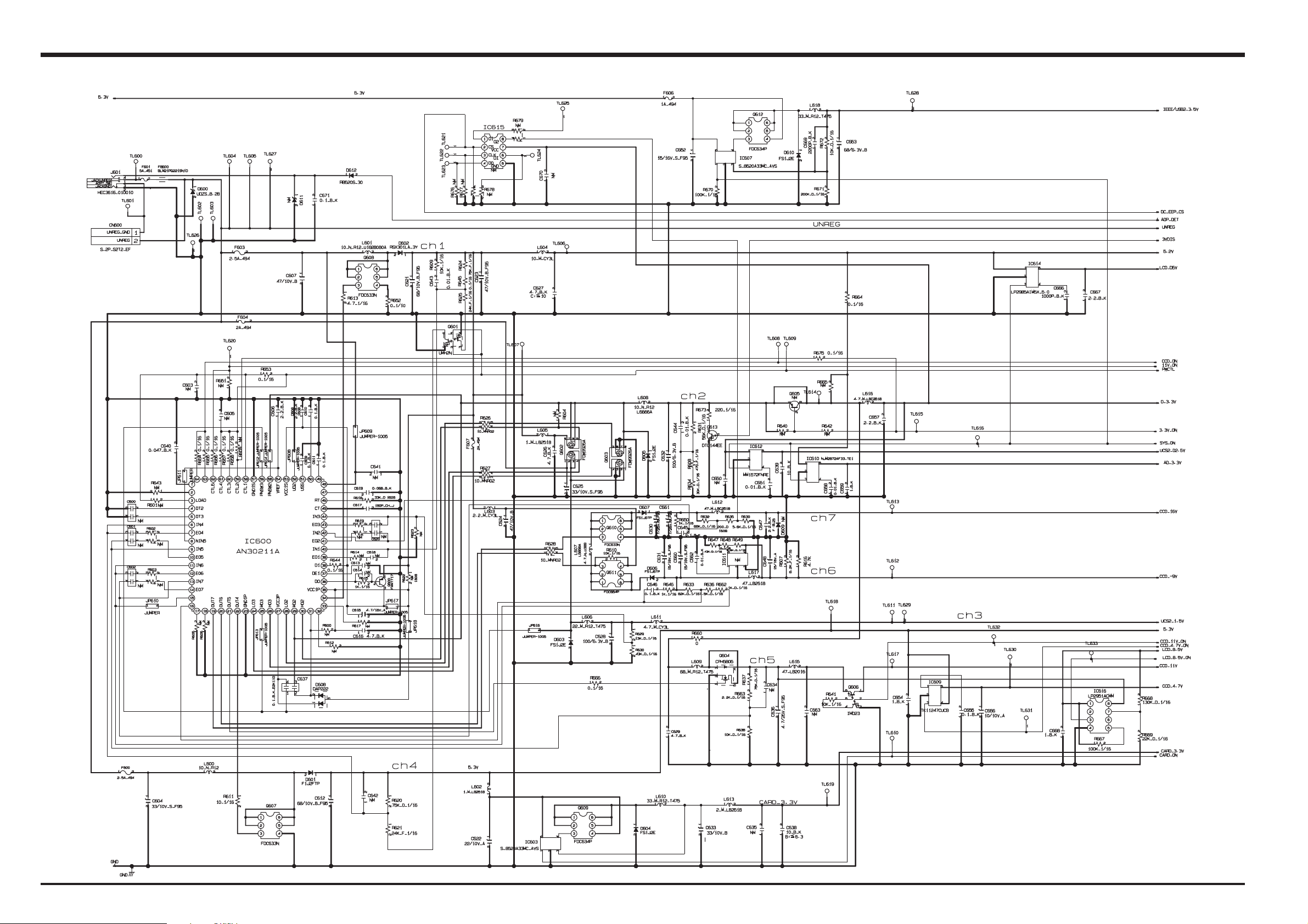
3. Schematics
3-6-2. DCDC BLOCK
FinePix S3Pro Service Manual
28

FinePix S3Pro Service Manual
3. Schematics
3-6-3. IEEE1394 BLOCK
29

3. Schematics
3-6-4. PROCESS BLOCK
FinePix S3Pro Service Manual
30
 Loading...