

FujiFilm FinePix S3 Pro User Manual
1
2
3
4
5
6
BL00430-201(1
)
Getting Ready
Basic
Photography
Advanced
Photography
Settings
Advanced
Features Playback
Connection
This manual will show you how to use your
FUJIFILM DIGITAL CAMERA FinePix S3 Pro correctly.
Please follow the instructions carefully.
OWNER’S MANUAL

Warning
EC Declaration of Conformity
To prevent fire or shock hazard, do not expose the unit to rain or moisture.
For customers in the U.S.A.
Tested To Comply
With FCC Standards
FOR HOME OR OFFICE USE
FCC Statement
This device complies with part 15 of the FCC Rules. Operation
is subject to the following two conditions: (1) This device may
not cause harmful interference, and (2) this device must
accept any interference received, including interference that
may cause undesired operation.
CAUTION
This equipment has been tested and found to comply with the
limits for a Class B digital device, pursuant to Part 15 of the
FCC Rules. These limits are designed to provide reasonable
protection against harmful interference in a residential
installation. This equipment generates, uses, and can radiate
radio frequency energy and, if not installed and used in
accordance with the instructions, may cause harmful
interference to radio communications. However, there is no
guarantee that interference will not occur in a particular
installation. If this equipment does cause harmful interference
to radio or television reception, which can be determined by
turning the equipment off and on, the user is encouraged to try
to correct the interference by one or more of the following
measures:
— Reorient or relocate the receiving antenna.
— Increase the separation between the equipment and receiver.
— Connect the equipment into an outlet on a circuit different from
that to which the receiver is connected.
— Consult the dealer or an experienced radio/TV technician for
help.
You are cautioned that any changes or modifications not
expressly approved in this manual could void the user’s authority
to operate the equipment.
Notes on the Grant:
To comply with Part 15 of the FCC rules, this product must be
used with a Fujifilm-specified ferrite-core video cable, IEEE 1394
cable, USB cable and DC supply cord.
For customers in Canada
CAUTION
This Class B digital apparatus complies with Canadian ICES-003.
Please read the Safety Notes (➡P.141) and make
sure you understand them before using the camera.
We
:
Name
:
Address
declare that the product
Product Name: FUJIFILM DIGITAL CAMERA FinePix S3 Pro
Manufacture’s Name: Fuji Photo Film Co., Ltd.
Manufacture’s Address: 26-30, Nishiazabu 2-chome, Minato-ku,
is in conformity with the following Standards
following the provision of the EMC Directive (89/336/EEC, 92/31/EEC and
93/68/EEC)and Low Voltage Directive (73/23/EEC).
Safety:EN60065
EMC:EN55022:1998 Classe B
Fuji Photo Film (Europe)G.m.b.H.
Heesenstrasse 31
40549 Dusseldorf, Germany
Tokyo 106-8620, Japan
EN55024:1998
EN61000-3-2: 1995 +A1:1998 +A2:1998
Dusseldorf, Germany November 1, 2004
Place Date Signature/Managing Director
Bij dit produkt zijn batterijen geleverd. Wanneer deze leeg zijn, moet u
ze niet weggooien maar inleveren als KCA
2 3

Contents
.........................................................................
Warning
EC Declaration of Conformity
..........................................................................
Preface
Accessories included
Camera parts and features
........................................
.....................................................
............................................
2
3
7
8
9
Top display panel
LCD monitor
Rear display panel
Viewfinder display
....................................................
............................................................
..................................................
...................................................
1 Getting Ready
ATTACHING THE STRAP
MOUNTING THE CAMERA LENS
Using CPU Nikkor lenses other than G-type lenses
Lens compatibility
CHARGING THE BATTERIES
LOADING THE BATTERIES
INSERTING THE MEDIA
CHECKING THE BATTERY CHARGE
TURNING ON AND OFF / SETTING THE DATE AND TIME
CORRECTING THE DATE AND TIME / CHANGING THE DATE ORDER
SELECTING THE LANGUAGE
DIOPTER ADJUSTMENT
LCD ILLUMINATOR
...............................................................................................................
..................................................................................................
....................................................................
.........................................................................................................................
........................................................................................................
............................................................................................................
................................................................................................................
...........................................................................................
.........................................................
.......................................................................................................
...............................................................................................................
........................................................................................................................
2 Basic Photography
BASIC OPERATION GUIDE
Command dials
TAKING PICTURES (P Auto-Multi Program)
Shooting with the camera held on end (vertically)
NUMBER OF AVAILABLE SHOTS
■ Standard number of shots for the media
AF-ASSIST ILLUMINATOR
SITUATIONS WHERE AUTOFOCUS MAY NOT WORK AS EXPECTED
USING AF LOCK
TAKING PICTURES WITH AE LOCK
DEPTH OF FIELD CHECK BUTTON
CCD PLANE INDICATOR
PLAYBACK MODE
VIEWING THE IMAGES (
Single-frame playback
Selecting images
Playback zoom
............................................................................................................................
.............................................................................................................................
..........................................................................................................................
.............................................................................................................................
...........................................................................................................
..................................................................................
.................................................................................................
.............................................................................................................
........................................................................................
...............................................................................................................
w PLAYBACK)
..................................................................................................................
..............................................................................................
......................................................................................
.......................................................................
..................................................................................
3 Advanced Photography
FOCUS SETTINGS
FOCUS SETTINGS
■ Focus-related custom settings
SELECTING THE FOCUS MODE
■ Focus modes
SELECTING THE AF AREA MODE
■ The displays shown in the viewfinder and on the top display panel are shown below.
SELECTING THE FOCUS AREA
MANUAL FOCUS
RELEASE MODES
, SINGLE-FRAME
4
......................................................................................................................
.............................................................................................
...............................................................................................
........................................................................................................................
............................................................................................
................................................................................................
.........................................................................................................................
...................................................................................................................
....................................
.....................................
........
12
12
13
15
16
17
18
19
21
22
24
25
26
27
28
29
29
30
33
34
36
37
37
38
39
40
41
42
42
43
43
43
44
45
45
46
46
47
47
48
49
50
. CONTINUOUS SHOOTING
9 SELF-TIMER PHOTOGRAPHY
p MULTIPLE EXPOSURE
METERING SYSTEMS
l Matrix (10-segment) metering
k Center-weighted metering
j Spot metering
ISO SENSITIVITY
EXPOSURE MODES
P AUTO-MULTI PROGRAM
Program chart
S SHUTTER-PRIORITY AUTO
A APERTURE-PRIORITY AUTO
M MANUAL
Bulb photography (
b EXPOSURE COMPENSATION
c AUTO EXPOSURE BRACKETING
FLASH PHOTOGRAPHY
FLASH PHOTOGRAPHY
SETTINGS FOR FLASH PHOTOGRAPHY
BUILT-IN FLASH
■ Flash control modes that can be used with the built-in flash
SYNCHRO MODES AND THEIR FEATURES
a FRONT SYNCHRO MODE
ag SLOW SYNCHRO MODE
ah REAR SYNCHRO MODE
as RED-EYE REDUCTION MODE
asg RED-EYE REDUCTION SLOW SYNCHRO MODE
TAKING PICTURES USING THE BUILT-IN FLASH
■ Effective range of the built-in flash
LENSES THAT CAN BE USED WITH THE BUILT-IN FLASH
FLASH EXPOSURE COMPENSATION
NIKON FLASH UNITS THAT CAN BE USED
PHOTOGRAPHY FUNCTION MENU
USING THE FUNCTION MENU WHEN TAKING PICTURES
WHITE BALANCE
QUALITY
RECORDED PIXELS
FILM SIMULATION
DYNAMIC RANGE
COLOR
TONE
SHARPNESS
AF AREA
FUNCTION LOCK
FUNCTION RESET
...............................................................................................................................
..................................................................................................................................
....................................................................................................................................
.......................................................................................................................................
..................................................................................................................................
................................................................................................................
.................................................................................................................
........................................................................................................................
......................................................................................................................
™)
..........................................................................................................................
....................................................................................................................
..................................................................................................................
...................................................................................................................
...........................................................................................................................
....................................................................................................................
..................................................................................................................
4 Advanced Features Playback
PLAYBACK FUNCTION MENU
USING THE FUNCTION MENU
HISTOGRAM
ERASING SINGLE-FRAME
...............................................................................................................................
.................................................................................................
...........................................................................................
.......................................................................................................
........................................................................................
..............................................................................................
....................................................................................................
................................................................................................
.............................................................................................
...................................................................................................
............................................................................................
......................................................................................
.............................................................................................................
.........................................................................
................................................
............................................................................
..............................................................................
................................................................................
.................................................................................
.......................................................................
.........................................
...................................................................
.......................................................................................
....................................................
......................................................................................
..............................................................................
.....................................................
...............................................................................................................
..................................................................................................
.........................................................................................................
50
51
52
54
54
54
54
55
56
57
58
59
60
61
63
64
66
66
67
67
68
68
68
69
69
69
70
71
72
73
74
76
77
78
79
79
80
80
81
81
82
82
83
84
85
86
1
2
3
4
5
6
5
Contents
LCD cover
Preface
SINGLE-FRAME PROTECT
MULTI-FRAME PLAYBACK
PLAYBACK MENU
o ERASING ALL FRAMES
i PROTECTING IMAGES: SET ALL / RESET ALL
u HOW TO SPECIFY PRINT OPTIONS (DPOF)
u DPOF SET FRAME
u DPOF (RESET ALL)
[ AUTOMATIC PLAYBACK
] TRIMMING
.............................................................................................................................
= LCD BRIGHTNESS
........................................................................................................
.........................................................................................................
........................................................................................................
..................................................................
......................................................................
................................................................................................................
..............................................................................................................
......................................................................................................
..............................................................................................................
5 Settings
SET-UP
USING THE SET-UP SCREEN
IMAGE DISPLAY
SETTING THE CUSTOM WB
COLOR SPACES
D-RANGE
AUTO ROTATE
FORMAT
FRAME NO.
DISCHARGING RECHARGEABLE BATTERIES
LIVE IMAGE
TWO-BUTTON RESET
CUSTOM SETTING (CSM)
.........................................................................................................................................
......................................................................................................
■ SET-UP menu options
Procedure when “PREVIEW” is set
Preview zoom
Histogram
...........................................................................................................................
.............................................................................................................................
...................................................................................................................................
Brightness warning and standard chart
■ When the exposure is not measured correctly
............................................................................................................
............................................................................................
......................................................................................
.......................................................................................................
.......................................................................
..........................................................................................................................
......................................................................................................................................
.............................................................................................................................
.......................................................................................................................................
...................................................................................................................................
..........................................................................
..................................................................................................................................
.................................................................................................................
...........................................................................................................
Cancelling custom settings
■ Custom settings list
........................................................................................................
................................................................................................................
6 Connection
CONNECTING TO A TV
USING THE AC POWER ADAPTER
CONNECTING TO A COMPUTER
USE AT DSC MODE
Disconnecting the camera
CONNECTING THE CAMERA DIRECTLY TO THE PRINTER — PictBridge FUNCTION
Specifying images for printing on the camera
Specifying images for printing without using DPOF (single-frame printing)
Disconnecting the printer
...............................................................................................................
............................................................................................
...............................................................................................
..................................................................................................................
..........................................................................................................
............................................................................
...............................
...........................................................................................................
..........
87
88
89
91
93
94
96
97
98
100
101
101
102
103
103
103
103
103
104
105
105
105
106
106
106
107
108
109
110
110
111
113
113
114
115
116
117
117
118
120
■ Test Shots Prior to Photography
For particularly important photographs (such as
weddings and overseas trips), always take a test
photograph and view the image to make sure that the
camera is functioning normally.
h Fuji Photo Film Co., Ltd. cannot accept liability for
any incidental losses (such as the costs of
photography or the loss of income from
photography) incurred as a result of faults with this
product.
■ Notes on Copyright
Images recorded using your digital camera system
cannot be used in ways that infringe copyright laws
without the consent of the owner, unless intended only
for personal use. Note that some restrictions apply to
the photographing of stage performances,
entertainments and exhibits, even when intended
purely for personal use. Users are also asked to note
that the transfer of memory cards (xD-Picture Card or
Microdrive) containing images or data protected under
copyright laws is only permissible within the
restrictions imposed by those copyright laws.
■ Liquid Crystal
If the LCD monitor is damaged, take particular care
with the liquid crystal in the monitor. If any of the
following situations arise, take the urgent action
indicated.
h If liquid crystal comes in contact with your skin
Wipe the area with a cloth and then wash thoroughly
with soap and running water.
h If liquid crystal gets into your eye
Flush the affected eye with clean water for at least
15 minutes and then seek medical assistance.
h If liquid crystal is swallowed
Flush your mouth thoroughly with water. Drink large
quantities of water and induce vomiting. Then seek
medical assistance.
■ Notes on Electrical Interference
If the camera is to be used in hospitals or aircrafts,
please note that this camera may cause interference
LCD cover
◆
◆
to other equipment in the hospital or aircraft. For
details, please check with the applicable regulations.
■ Handling Your Digital Camera
This camera contains precision electronic
components. To ensure that images are recorded
correctly, do not subject the camera to impact or
shock while an image is being recorded.
■ Trademark Information
h and xD-Picture Card™ are trademarks of
Fuji Photo Film Co., Ltd.
h IBM PC/AT is a registered trademark of International
Business Machines Corp. of the U.S.A.
h Macintosh, Power Macintosh, iMac, PowerBook, iBook
and Mac OS are trademarks of Apple Computer, Inc.,
registered in the U.S. and other countries.
h Adobe Acrobat
Systems Incorporated of the U.S.
h Microsoft, Windows, and the Windows logo are
trademarks, or registered trademarks of Microsoft
Corporation in the United States and/or other
countries. Windows is an abbreviated term referring
to the Microsoft
✽ The “Designed for Microsoft
refers to the camera and the driver only.
h Other company or product names are trademarks or
registered trademarks of the respective companies.
®
Reader®is a trademark of Adobe
®
Windows®Operating System.
®
Windows®XP” logo
■ Explanation of Color Television System
NTSC: National Television System Committee, color
television telecasting specifications adopted
mainly in the U.S.A., Canada and Japan.
PAL: Phase Alternation by Line, a color television
system adopted mainly by European countries
and China.
■ Exif Print (Exif ver. 2.2)
Exif Print Format is a newly revised digital camera file
format that contains a variety of shooting information
for optimal printing.
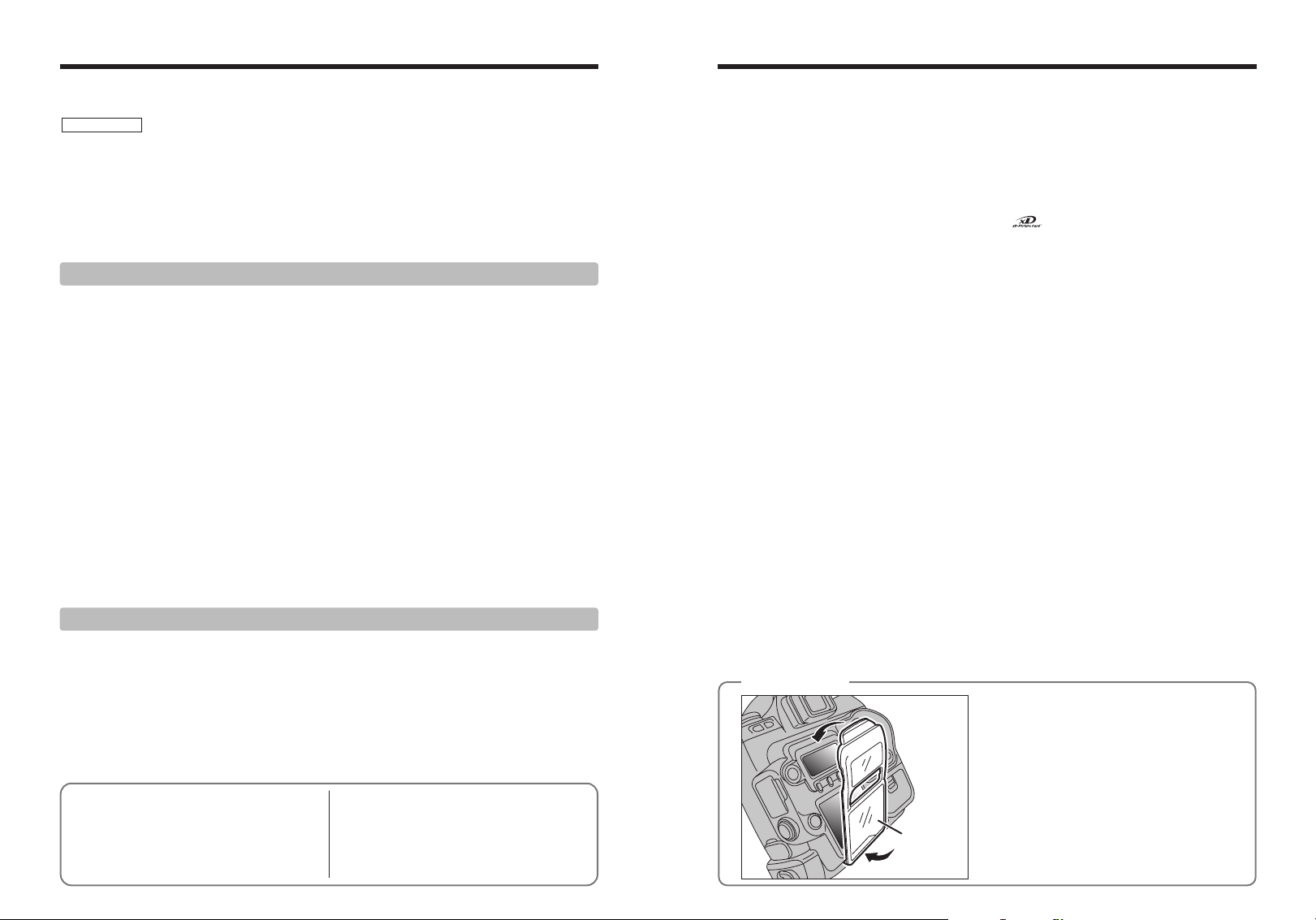
To prevent soiling or damage to the LCD monitor,
attach the enclosed LCD cover to the camera when
you are carrying or not using the camera.
Attach the LCD cover by first fitting it into the grooves
below the camera’s LCD monitor.
System Expansion Options
Accessories Guide
Notes on Using Your Camera Correctly
Cleaning the CCD
Notes on the Power Supply
Applicable Batteries
Notes on the Batteries
Using the AA-size Ni-MH Batteries
.......................................
....................................................
.....................................................
.......................................
..............................................
...........................................
....................
.......................
121
122
124
Notes on the Media
125
Warning Displays
129
Troubleshooting
129
Specifications
129
Explanation of Terms
129
Safety Notes
Notes on Using the Battery Charger
AC Power Adapter
................................................
...................................................
......................................................
.........................................................
............................................................
................................................
..............................................................
.....................
130
130
131
132
136
138
140
141
76
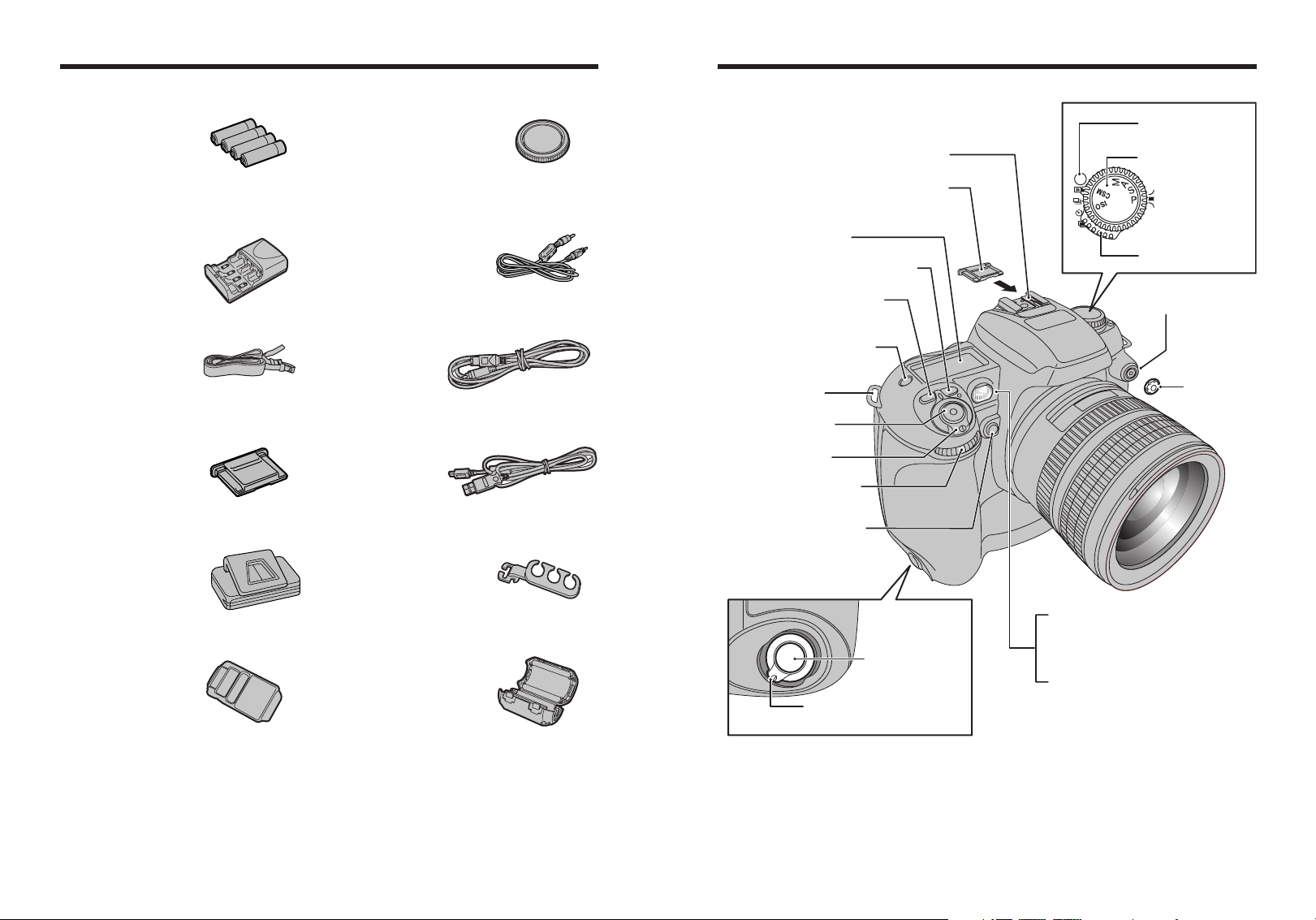
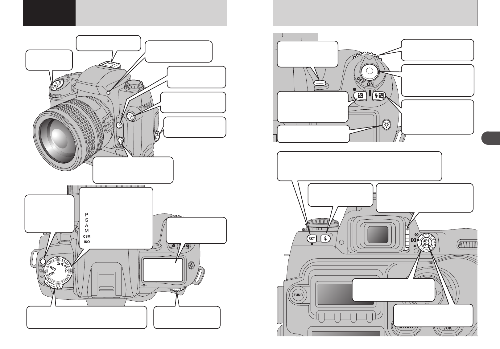
Accessories included
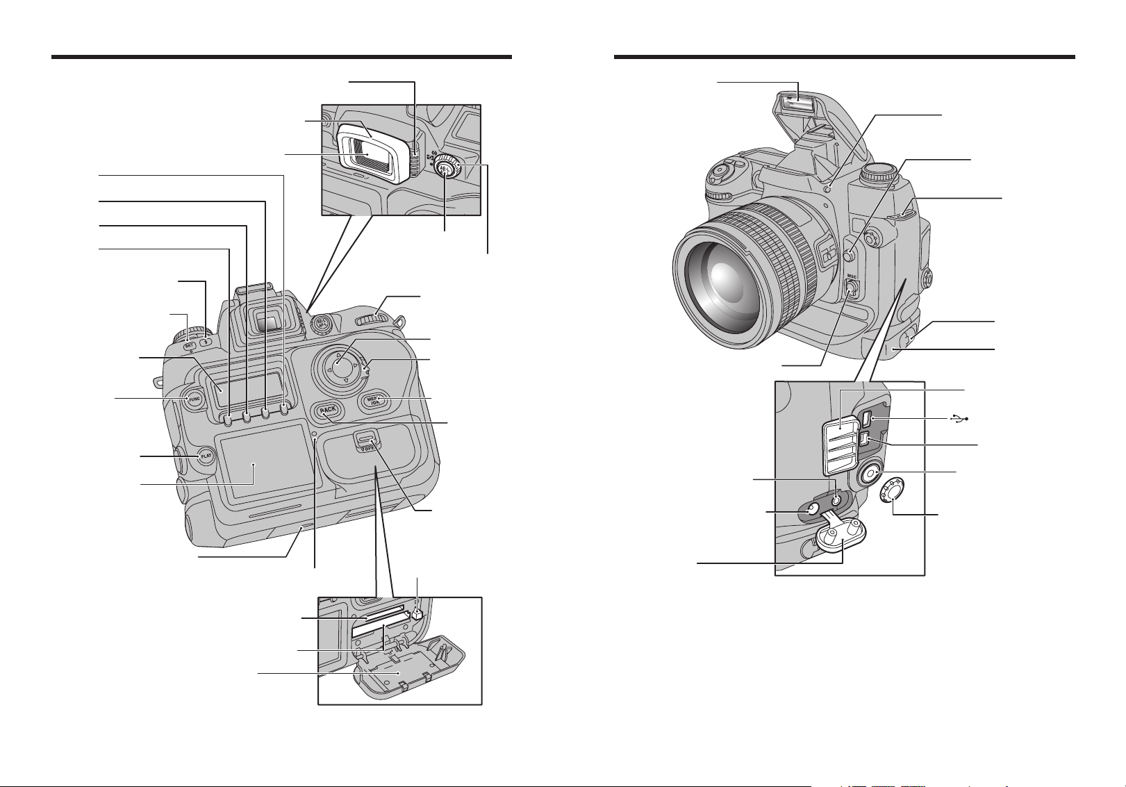
AF-assist illuminator
(P.38)
Self-timer lamp
(P.51)
Red-eye reduction lamp
(P.69)
Accessory shoe
(P.75)
Accessory shoe cover
Power switch
(P.26)
Sub-command dial
(P.33)
Depth of field check button
(P.42)
Shutter button for
vertical shooting
(P.36)
Strap mount
(P.16)
Flash exposure compensation
button
(P.73)
Exposure compensation button
(P.63)
To p display panel
(P.12)
LCD illuminator button
(P.29)
Shutter button
(P.36)
Release mode switch
unlock button
Exposure mode dial
Release mode switch
Synchronizing
terminal cap
Synchronizing terminal
Lock lever for vertical shooting
(P.36)
Camera parts and features
✽ Refer to the pages in parentheses for information on
using the camera parts or features.
h AA-size Ni-MH Batteries (HR-AA) (4)
h Battery charger BCH-NH2 (1)
✽Plug-in and cord-attached types are provided
depending on the intended country of use.
h Strap (1)
h Accessory shoe cover (1)
Fitted on the camera body
h Eyepiece cap (1)
h Camera body cap (1)
Fitted on the camera body
h Video cable (1)
(approx. 1.5 m (4.9ft.), mini-plug (3.5 mm-dia.) to
pin-plug cable)
h IEEE 1394 4-pin to 6-pin cable (1)
(approx. 1.5 m (4.9ft.))
h USB cable (mini-B) (1)
h Cable holder (1)
h LCD cover (1)
Fitted on the camera body
8 9
h Clamp filter (1)
h Synchronizing terminal cap (1)
Fitted on the camera body
h Remote release socket cap (1)
Fitted on the camera body
h Battery holder (1)
Fitted on the camera body
h CD-ROM: Software for FinePix AX (1)
h Owner’s Manual (this manual) (1)
h Software Quick Start Guide (1)
Camera parts and features
F4 button
F3 button
F2 button
F1 button
Synchro mode button
Auto Exposure Bracketing
(P.64)
button
Rear display panel
(P.14)
FUNC button
(P.76, 84)
PLAY button
LCD monitor
(P.68)
(P.43)
(P.12)
Diopter adjustment knob
Rubber eyecup
Viewfinder
AE-L/AF-L button
Metering system selector dial
Main-command dial
4-direction button
4-direction button
MENU/OK button
Slot cover
unlock button
(P.33)
lock switch
BACK button
(P.70)
Flash
Focus mode selector switch (P.46)
VIDEO OUT (Video output)
socket
DC IN 5V (power input) socket
Flash pop-up button (P.70)
Lens release button
Strap mount
Battery holder
release catch
Battery holder
Digital terminal cover
USB socket (mini-B)
IEEE 1394 socket
Remote release socket
(10-pin terminal)
Remote release socket cap
(P.62)
Tripod mount
Access lamp
xD-Picture Card slot
CF / Microdrive slot
Slot cover
(P.116)
CF / Microdrive
eject button
Terminal cover
10 11
Camera parts and features
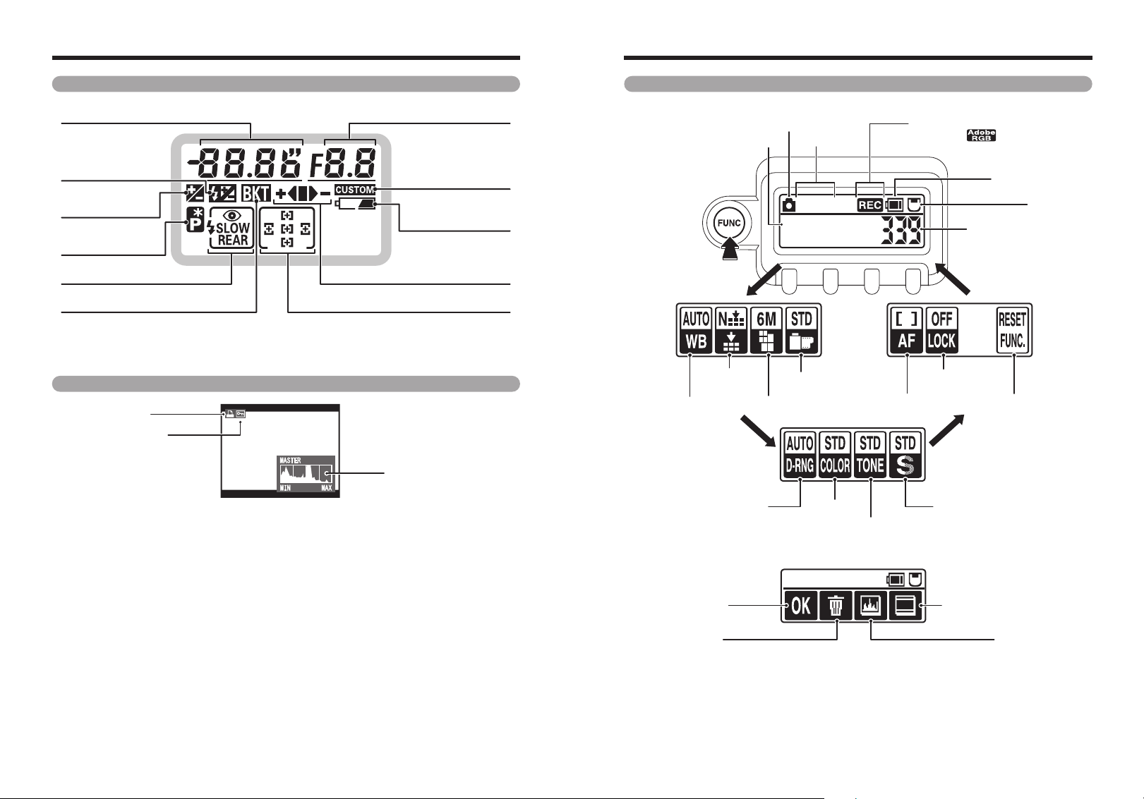
Protection
DPOF
Histogram
Top display panel Rear display panel
Shutter speed / Exposure
compensation value
Flash exposure
compensation
Exposure
compensation
Flexible Program
(P.56)
Flash synchro mode (P.68) Bracketing bar graphs (P.64)
Auto Exposure Bracketing (P.64) Focus area (P.47)
!
The LCD used in the top display panel will turn dark at high temperatures and will respond a little more slowly at low
●
temperatures. However, it will operate normally again at normal temperatures.
(P.73)
(P.63)
Custom Setting (P.110)
Battery level warning
Aperture
(P.25)
■ During shooting
Press the “FUNC”
button to switch
between functions.
Photography mode
Date / Time
Sensitivity
ISO200
01 / 01 / 2004
12 : 00 AM
Recording icon (when recording)
/ Color space
(when AdobeRGB is set)
Battery charge
indicator
Media
Number of available
shots
LCD monitor
White balance Recorded pixels
!
There may be some unevenness in the brightness at the bottom of the LCD monitor. This is due to variations in the
●
lighting of the LCD itself and is not a fault.
h Photographed image display: For checking
12 13
Quality
Dynamic range
Record
Erase
Film simulation
AF area mode
Color
To ne
Function lock
Function reset
Sharpness
Standard chart display (P.103)
Histogram (P.103)
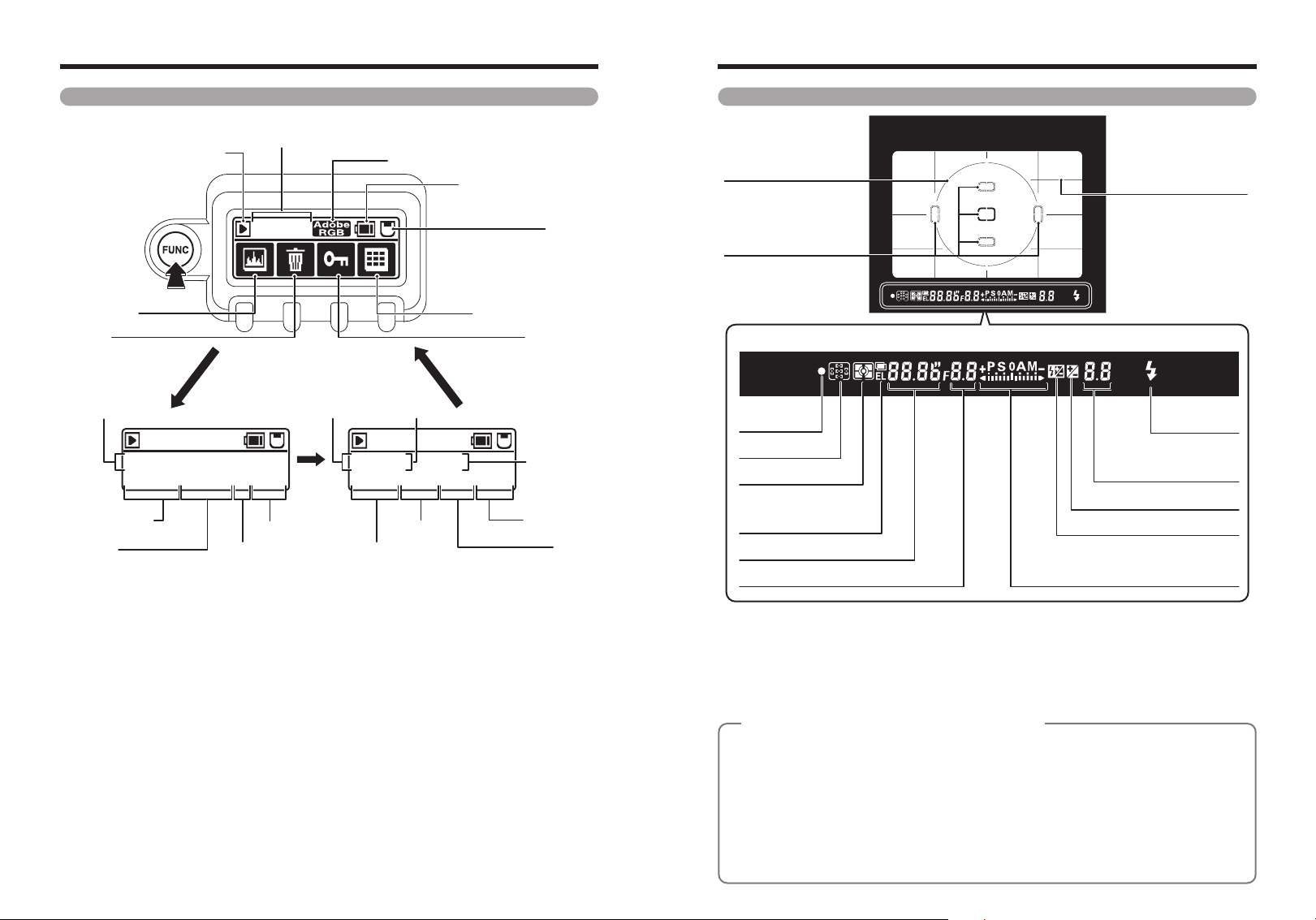
Camera parts and features
Rear display panel
■ During playback
Playback mode
Press the “FUNC”
button to switch
between functions.
Histogram
Erase
Date / Time
100-0009
01 / 01 / 2004 12 : 00 AM
WB:AUTO NORMAL 6M F:STD
White balance
Quality
Frame number
100-0009
Film simulation
Recorded pixels
Color space (only AdobeRGB shown)
Shutter speed Aperture
100-0009
125 F5.6 ISO200
STD
:
AUTO C
:
D
Color
Dynamic range
Battery charge indicator
Multi-frame playback
S:STD
T:STD
Sharpness
Media
Protection
Sensitivity
To ne
Viewfinder display
12mm-dia reference
circle for centerweighted metering area
(P.54)
Focus area
Spot metering area
(P.54)
● Viewfinder information display
Focus
indicator
(P.36)
Focus area
Metering system (P.54)
Multiple exposure (P.52)
AE-L (Auto exposure lock)
indicator
Shutter speed
Aperture
(P.47)
(P.41)
On-Demand Grid Lines
Flash ready-light
Exposure compensation value
compensation value
Exposure compensation (P.63)
Flash exposure compensation (P.73)
Exposure mode (P.56-62) / Electronic
analog exposure display / Exposure
compensation value display
/ Flash exposure
(P.111)
(P.70)
(P.63, 73)
(P.63)
!
The viewfinder will be dark without battery power but brightens after installation of fresh batteries. This is not a
●
malfunction.
!
The LCD panel in the upper part of the viewfinder (focus area and On-Demand Grid Lines) will become paler at high
●
temperatures and will become darker and respond a little more slowly at low temperatures. However, it will operate
normally again at normal temperatures.
!
The LCD panel in the viewfinder display (where the icons and numbers are displayed) will turn dark at high temperatures
●
and will respond a little more slowly at low temperatures. However, it will operate normally again at normal temperatures.
About Advanced Focusing Screen Display
◆
The new Advanced Focusing Screen Display of the FinePix S3 Pro employs the convenient Vari-Brite
Focus Area display system; it enables clear display of the focus brackets at the selected focus area in
the viewfinder for easy identification. When the finder image is bright, the focus brackets are displayed
in black and when the finder image is dark, the focus brackets are momentarily illuminated in red. The
selected focus area can be identified easily in both bright and dark conditions with this function.
Also, the new Advanced Focusing Screen Display allows the superimposition of On-Demand Grid
Lines. The grid lines can be displayed by using Custom Setting Menu #2 (➡P.111). These grids assist
you in composing the frame, in taking landscape pictures or in shifting/tilting PC-Nikkor lenses.
✽ Due to characteristics of the LCD used in the Vari-Brite Focus Area display system, a thin line
outside the selected focus area may also be displayed or the entire viewfinder may be illuminated in
14 15
red under certain conditions. These are not malfunctions.
◆
Fastener A
Fastener B
1 Getting Ready
Cable
holder
IEEE 1394
DC IN 5V
Strap
mount
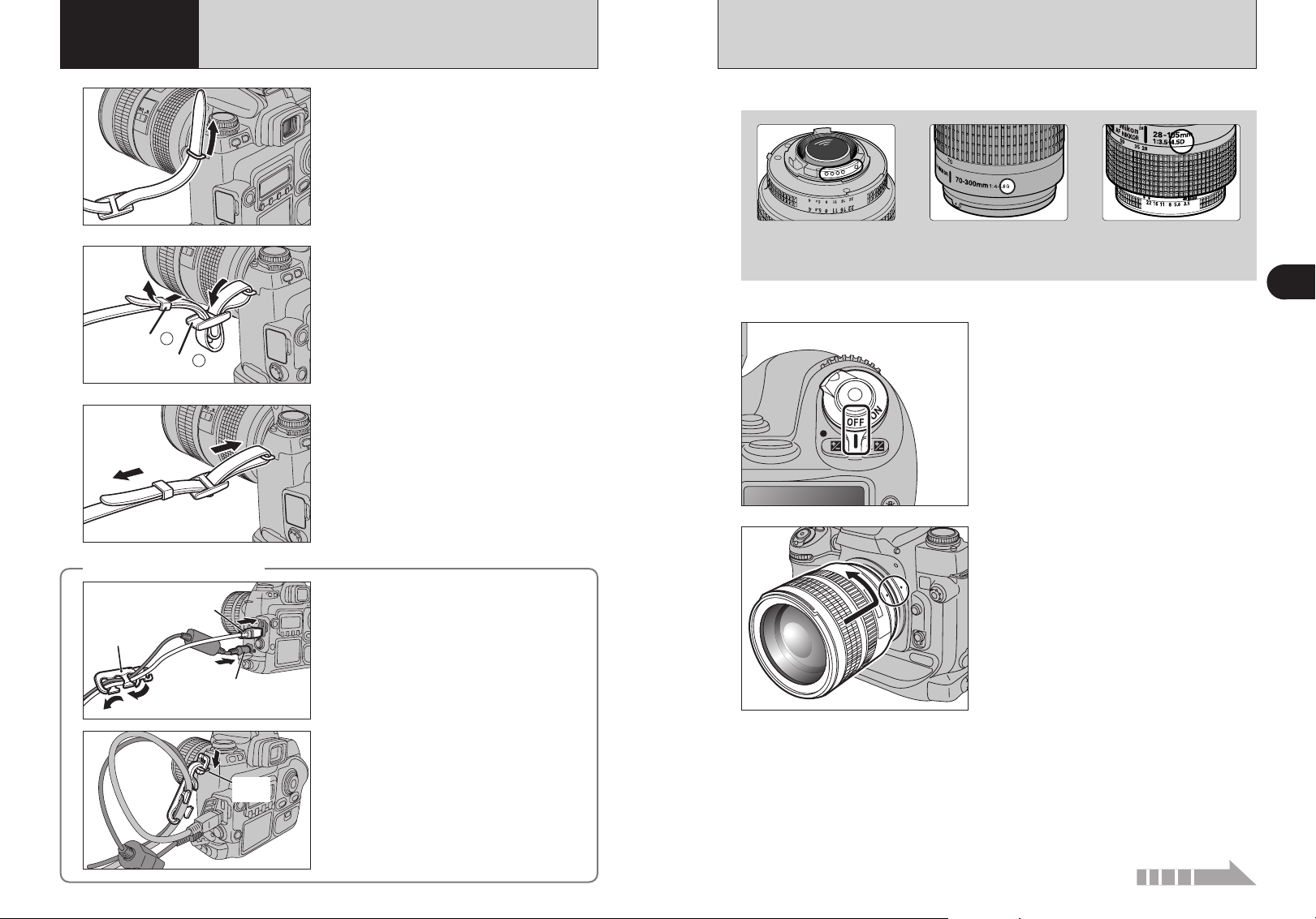
ATTACHING THE STRAP
MOUNTING THE CAMERA LENS
1
2
3
Using the cable holder
◆
Pass one end of the strap through the strap mount
on the camera body.
Pass the end of the strap through the fastener A
and B as shown in the figure.
Adjust the strap length. Use the same procedure to
attach the other end of the strap to the other strap
mount.
!
Check that the strap is pulled tight after it is attached.
●
◆
Feed the cables through the cable holder.
Check the lens type.
1
CPU contacts of CPU lens
The lens is fitted with CPU
signal contacts.
!
See “Lens compatibility” (➡P.19) for details.
●
2
3
G-type Nikkor lens
(without aperture ring)
Set the Power switch to “OFF” to turn the camera
off.
Position lens in the camera’s bayonet mount so
that the mounting indexes on lens and camera
body are aligned, then twist lens counterclockwise
until it locks into place.
!
Always change the lens in an area free of dirt and dust.
●
!
When attaching the lens, take care not to press the lens
●
release button.
!
When the lens is not attached or when a non-CPU Nikkor
●
lens is attached and the power switch is turned on, “
blinks in the top display panel and viewfinder, and the shutter
cannot be released. See P.20 for a non-CPU lens.
!
Take care not to mount the lens when it is at an angle to the
●
camera as this can damage the lens mount on the camera.
CPU Nikkor lens other
than G-type
(with aperture ring)
§”
1
Getting Ready
Attach the cable holder to the strap mount.
16 17
Continued
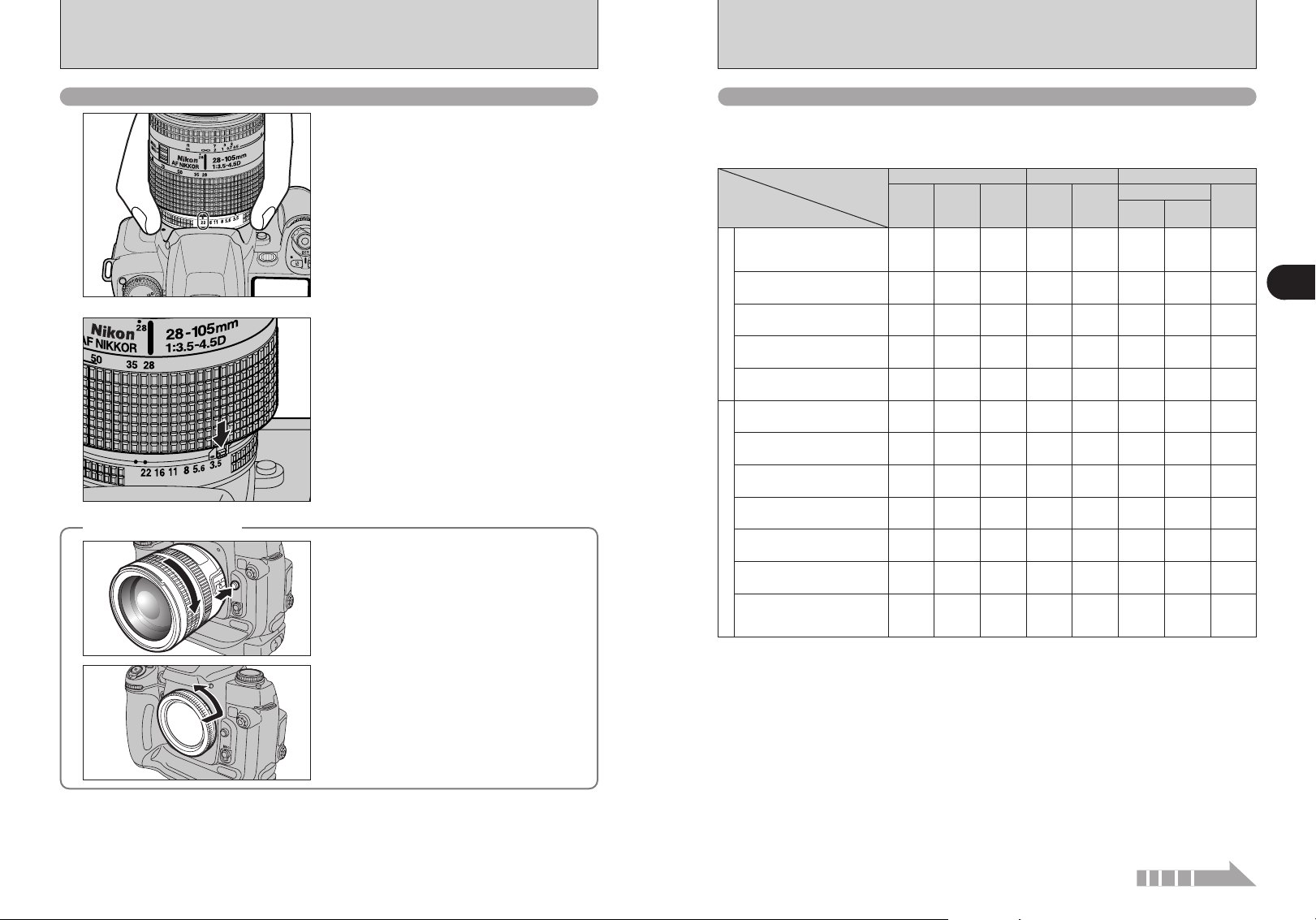
MOUNTING THE CAMERA LENS
Using CPU Nikkor lenses other than G-type lenses
Set the aperture ring to the minimum aperture.
1
Lock the aperture ring. If you turn the camera on
2
Removing the lens
◆
◆
without first selecting the minimum aperture (the
aperture setting with the largest number), “¡”
flashes on the top display panel and in the
viewfinder, and the shutter will not operate.
Push and hold the lens release button, then turn the
lens clockwise.
While the lens is removed from the camera, fit the
camera body cap provided onto the camera to
protect the inside of the camera and prevent soiling
of the mirror and viewfinder screen.
You can also use the Nikon BF-1A Body Cap.
Lens compatibility
Use a CPU lens (except IX-Nikkor) with this camera. D- or G-type AF lenses give you access to all
available functions (➡P.17).
■ Types of CPU lenses and other usable lenses/accessories
Focus modeMode
Manual with
electronic
Autofocus
Lens/accessories
D-type AF Nikkor✽3,
G-type AF Nikkor
AF-S, AF-I Nikkor
PC Micro-Nikkor
✽2
85 mm f/2.8D
AF-I/AF-S Teleconverter
CPU Nikkor
Non-D/G-type AF Nikkor (except
AF Nikkor for F3AF)
AI-P Nikkor
AI-S or AI type Nikkor,
Series-E, AI-modified Nikkor
Medical-Nikkor
120 mm f/4
Reflex-Nikkor
✽9
PC-Nikkor
AI-S or AI type
Teleconverters
Non-CPU Nikkor
Bellows Focusing
Attachment PB-6
Auto Extension Rings
(PK-11A, PK-12,
PK-13 and PN-11)
✓: Compatible, —: Imcompatible
✽ 1 Spot metering area can be shifted with focus area selector (➡P.54) with CPU Nikkor lens.
✽ 2 IX-Nikkor lenses cannot be attached.
✽ 3 This camera is compatible with the Vibration Reduction function of the VR Nikkor lens.
✽ 4 The camera’s exposure metering and flash control system do not work properly when shifting and/or tilting the lens, or
when using an aperture other than the maximum aperture.
✽ 5 Without shifting and/or tilting the lens.
✽ 6 Compatible with AF-S and AF-I Nikkor except AF-S 17-35 mm f/2.8D IF-ED, AF-S 28-70 mm f/2.8D IF-ED, AF-S 12-
24mm f/4G, AF-S DX ED 17-55mm f/2.8G, AF-S DX ED 18-70mm f/3.5-4.5G, AF-S ED 24-85mm f/3.5-4.5G and AF-S
VR ED 24-120mm f/3.5-5.6G.
✽ 7With maximum effective aperture of f/5.6 or faster.
✽ 8With maximum aperture of f/5.6 or faster.
✽ 9 Some lenses/accessories cannot be attached (➡P.20).
✽ 10 With exposure mode set to Manual. The exposure meter cannot be used.
✽ 11 With exposure mode set to Manual and shutter speed set to 1/60 sec. or slower but the exposure meter cannot be
used.
✽ 12 Can be mounted when used with the Nikon Auto extension ring.
i Reprocopy Outfit PF-4 can be attached in combination with Nikon Camera Holder PA-4.
✽3
,
✽4
✽6
✽12
rangefinder
✓✓✓✓✓✓
—
✓
✽5
✓
✽7
✽7
✓
✓✓✓✓✓
—
—
—
——
—
—
—
—
✽8
✓
✽8
✓
✓✓
✽5
✓
✽7
✓
✽7
✓
✽7
✓
Exposure mode
Any mode
other than
Manual
✓
M
—
M
3D 10-
segment
✓✓
✓✓✓✓
—
✓✓✓
—
✓
✓
✓
✓
✓
✓
✓
—
✓
—
✓
—
✓
—
✓
—
✓
—
✓
—
✽10
———
✽11
———
✽10
———
✽10
———
✽10
———
✽10
———
✽10
———
Metering system
Matrix
10-
segment
—
—
—
Weighted,
✓✓
✓✓
Center-
✽1
Spot
✓
✓
✓
1
Getting Ready
18 19
Continued
MOUNTING THE CAMERA LENS
CHARGING THE BATTERIES
G-type Nikkor and other CPU Nikkor lens
◆
h The G-type Nikkor lens has no aperture ring; aperture should be selected from camera body. Unlike
other CPU Nikkor lenses, aperture does not need to be set to minimum (largest f-number).
h CPU Nikkor lenses other than G-type Nikkor lens have an aperture ring. Set the lens aperture to its
minimum and lock. When the lens is not set to its minimum aperture setting and the power switch is
turned on, “
◆
Set exposure mode to “M” Manual with a non-CPU lens (When other modes are selected, shutter
cannot be released). The camera’s exposure meter cannot be used and the aperture cannot be set
using the Sub-command Dial when using non-CPU lenses. “
indication in the top display panel and viewfinder; set/confirm aperture using the lens aperture ring.
◆
The following Nikkor lenses/accessories cannot be attached to the FinePix S3 Pro (otherwise camera
body or lens may be damaged):
h TC-16A Teleconverter
h Non-AI lenses
h 400mm f/4.5, 600 mm f/5.6, 800 mm f/8 and 1200 mm f/11 with Focusing Unit AU-1
h Fisheye 6 mm f/5.6, 7.5 mm f/5.6, 8 mm f/8 and OP 10 mm f/5.6
h Old type 21 mm f/4
h K1, K2 ring, Auto Extension Ring PK-1, PK-11, Auto Ring BR-2, BR-4
h ED 180-600 mm f/8 (No. 174041-174180)
h ED 360-1200 mm f/11 (No. 174031-174127)
h 200-600 mm f/9.5 (No. 280001-300490)
h 80 mm f/2.8, 200 mm f/3.5 and TC-16 Teleconverter for F3AF
h PC 28 mm f/4 (No. 180900 or smaller)
h PC 35 mm f/2.8 (No. 851001-906200)
h Old type PC 35 mm f/3.5
h Old type Reflex 1000 mm f/6.3
h Reflex 1000 mm f/11 (No. 142361-143000)
h Reflex 2000 mm f/11 (No. 200111-200310)
¡” blinks in the top display panel and viewfinder and the shutter cannot be released.
When a non-CPU lens is attached
Nikkor lenses/accessories that cannot be attached to the FinePix S3 Pro
◆
◆
§” appears in place of the aperture
◆
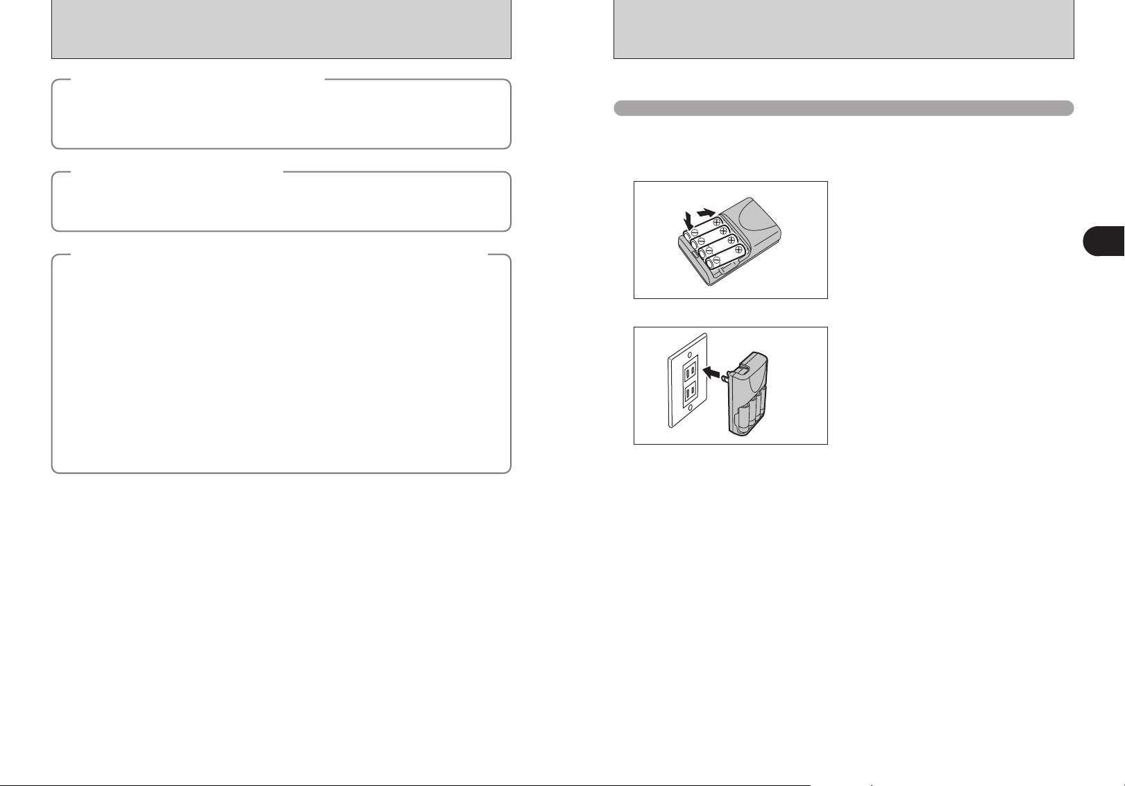
Charge the AA-size Ni-MH batteries (HR-AA).
Batteries that can be charged
h AA-size Ni-MH batteries (included)
!
Always use the battery charger BCH-NH2 bundled with the camera to charge Ni-MH batteries. Attempting to charge
●
batteries other than those specified for use with the charger (such as manganese, alkaline or lithium batteries) can cause
the batteries to burst or leak. This could result in a fire or injury and consequent damage to the surroundings.
Load the Ni-MH batteries (included) into the battery
1
2
✽Plug-in and cord-attached types are provided
depending on the intended country of use.
charger BCH-NH2 bundled with the camera
correctly as indicated by the polarity icons.
!
The Ni-MH batteries are not fully charged when purchased
●
and must be fully charged before being used.
!
When first used after purchasing or when left unused for a
●
long period, charge and discharge the battery using the
camera’s “Discharging rechargeable batteries” function and
then recharge them (➡P.107).
!
If the terminals of battery are soiled, it may not be possible to
●
charge them. Clean the battery terminals and battery charger
terminals with a clean, dry cloth.
Plug the battery charger into a power outlet to
begin charging. After completing the charging, the
charging lamp turns off. Unplug the battery charger
from the power outlet when it is not in use.
!
If Ni-MH batteries are charged repeatedly before they are
●
fully discharged, the battery charge indicator will appear while
there is still ample charge remaining in the batteries. At that
time, discharge and recharge them several times using the
camera’s “Discharging rechargeable batteries” function
(➡P.107).
!
The socket-outlet shall be installed near the equipment and
●
shall be easily accessible.
!
The shape of the plug and socket-outlet depends on the
●
country of use.
1
Getting Ready
20 21
LOADING THE BATTERIES
Compatible Batteries
h AA-size Ni-MH batteries (HR-AA) (4)
How to use the battery
◆
h Use only Ni-MH (nickel-metal hydride) batteries.
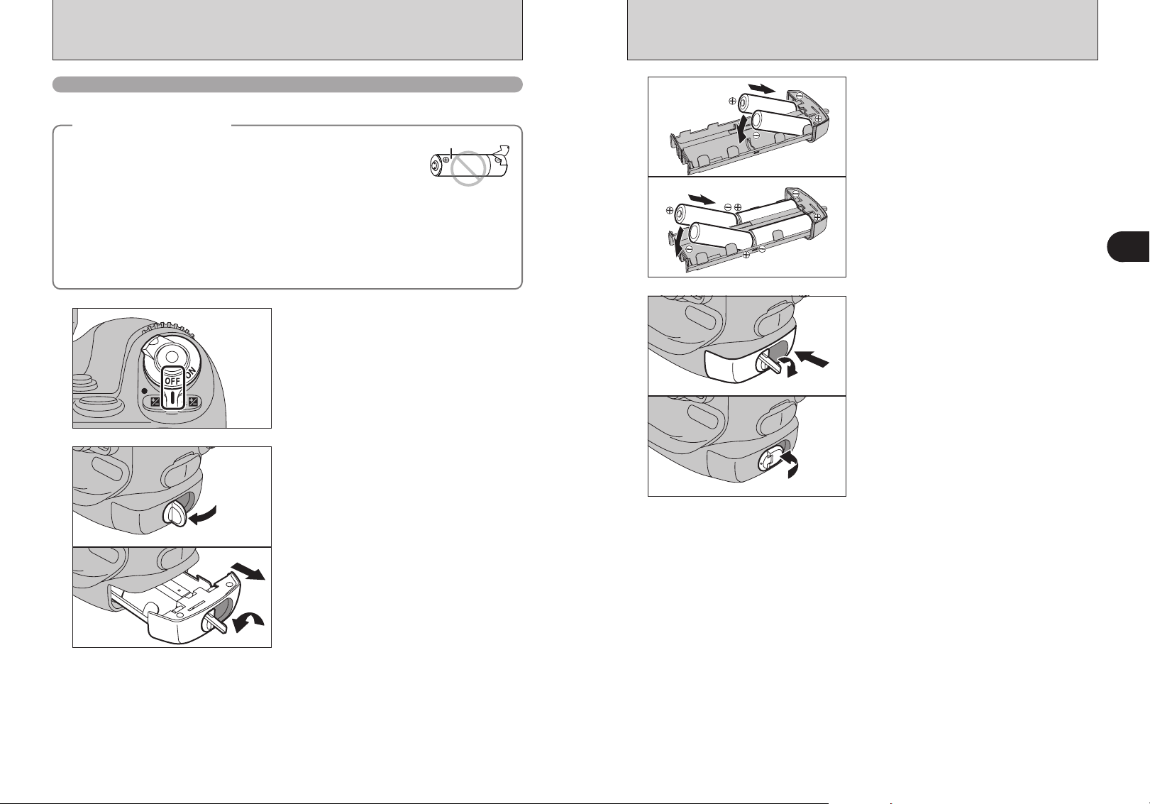
h Never use the following types of batteries, as they could cause serious
problems such as battery fluid leakage or overheating:
1. Batteries with split or peeling outer casings
2. Combinations of different types of batteries or new and used batteries
together
h Soil (such as fingerprints) on the battery terminals makes the batteries charge less reducing the
number of images they will allow you to take. Carefully wipe the battery terminals with a soft dry cloth
before loading.
h See P.129 for other notes on using batteries.
h When first used after purchasing or left unused for a long period, the time for which AA-size Ni-MH
rechargeable batteries can be used may be shorter. You are advised to check the detailed
information provided on P.129 and then charge the batteries before using the camera (within 1 week).
1
2
◆
Outer casing
Set the Power switch to “OFF” to turn the camera
off.
1Lift out the battery holder release catch.
2Turn the battery holder release catch
counterclockwise to unlock the battery holder.
3Pull the battery holder out.
01
3
4
04
03
02
01
03
02
Load the AA-size Ni-MH rechargeable batteries in
the direction indicated by the ≠ and – labels on
the holder. Align the battery ends with the terminals
in the sequence shown in the figure and then
slowly push them into the place.
!
Remove the batteries more easily by pushing the batteries
●
upwards from the gap at the opposite end from the battery
holder release catch.
Push the battery holder in and hold it in place as
you turn the battery holder release catch clockwise
to securely lock the battery holder.
01
1
Getting Ready
03
02
22 23
Access lamp
INSERTING THE MEDIA
Gold marking
CF/Microdrive
eject button
ISO200
09 / 23 / 2004
10 : 00 AM
3
Blinking
Lit
Lit
1
2
Use either xD-Picture Card or CF/Microdrive as recording media in the FinePix S3 Pro.
h If an xD-Picture Card and a CF/Microdrive are inserted at the same time, images will be recorded
onto the media selected as the “MEDIA” (➡P.102).
h Data cannot be copied between the two media types on the FinePix S3 Pro.
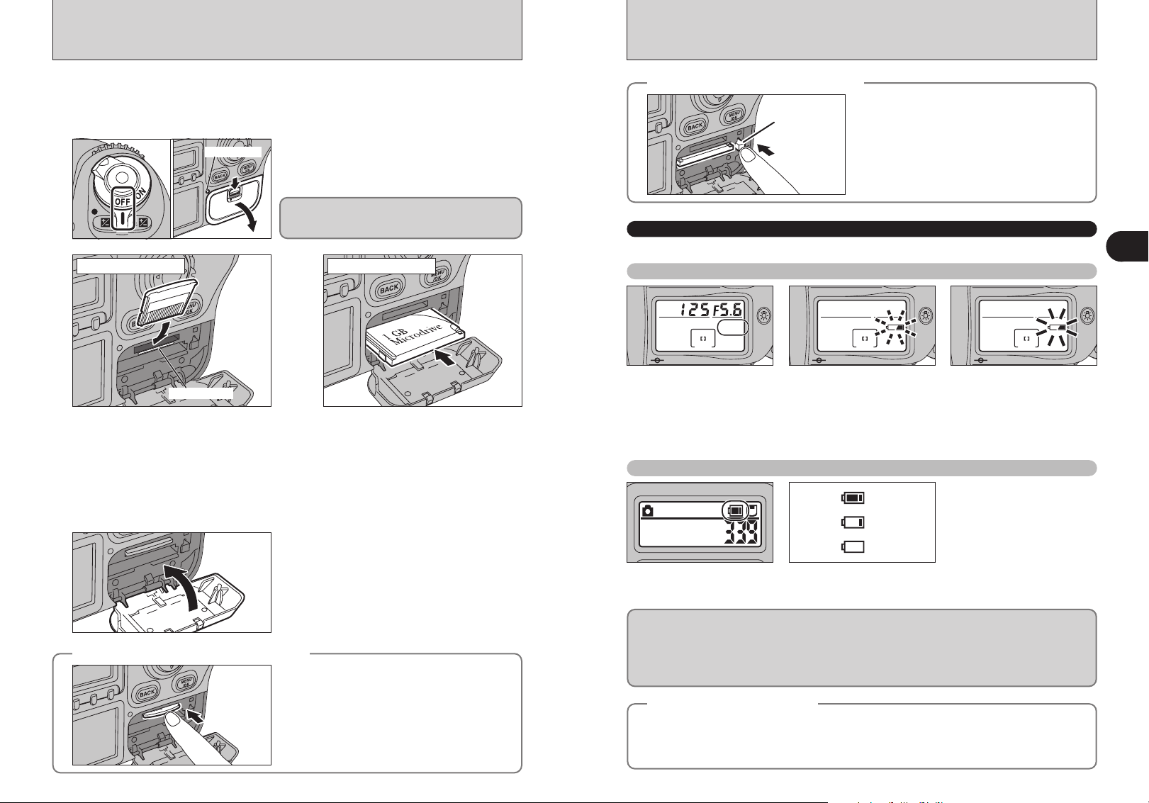
Set the Power switch to “OFF” and check that the
1
xD-Picture Card CF/Microdrive
2
Align the gold marking on the xD-Picture
Card slot with the gold contact area on
the xD-Picture Card and push the card
firmly all the way into the slot.
!
Insert only the appropriate media types into the xD-Picture Card and CF/Microdrive slots. Inserting the incorrect
●
media will damage the camera or media.
!
If the media is oriented incorrectly, it will not go all the way into the slot. Do not apply force when inserting an xD-
●
Picture Card or CF/Microdrive.
!
If the media is not fully inserted into the slot, “`” appears.
●
access lamp is off. Then open the slot cover.
Never open the slot cover while the camera is on.
This could destroy the image data or damage the
media itself.
Push the CF/Microdrive firmly all the way
into the CF/Microdrive slot.
Compatibility is listed on Fujifilm website:
http://home.fujifilm.com/products/digital/
Close the slot cover.
3
How to replace the xD-Picture Card
◆
24 25
◆
Push the xD-Picture Card into the slot and then
slowly remove your finger. The lock is released and
the xD-Picture Card is pushed out.
How to replace the CF/Microdrive
◆
◆
Open the slot cover, press the CF/Microdrive eject
button and remove the CF/Microdrive.
!
When storing CF/Microdrives, always use the special
●
protective case.
CHECKING THE BATTERY CHARGE
Turn the camera on and check the battery charge indicator.
Top display panel
1No icon
Batteries charged.
2Blinking
No remaining battery charge.
Camera shutting down.
3Lit
Lights when there is no
remaining battery charge and
the camera shutdown
procedure has been completed.
The batteries must be replaced.
Rear display panel
1There is ample charge in
the batteries.
2The batteries are flat.
Have replacement batteries
ready.
3The batteries are fully
!
If you turn the camera on again after the icon in 3 has been displayed, the
●
icon in 1 may reappear but there is actually no charge left in the batteries and
they must be replaced.
h If the camera loses power while it is shooting or saving an image, it cannot save the photographed
image. Note the battery level carefully when shooting long-exposure images (e.g. bulb photography)
or when shooting images that will take some time to save (continuous shooting or shots with the
quality set to “HIGH”).
h Use the optional AC adapter (AC-5VX) when camera is used for long periods for indoor shots, etc.
The camera displays no battery level icons when the AC adapter is used.
Auto Power Off Function
◆
If you leave the camera turned on without using it, this function automatically turns the camera off (➡P.112).
When the Auto Power Off function has turned the camera off, restore power to the camera by pressing the
shutter button on the top of the camera down halfway or by pressing the LCD illuminator button.
!
Auto Power Off cannot be cancelled using the shutter button for vertical shooting.
●
◆
depleted. You must replace
the batteries.
1
Getting Ready
DATE/TIMEDATE/TIME
2004 . 1 . 12004 . 1 . 1
12 : 00 AM12 : 00 AM
YYYY.MM.DDYYYY.MM.D D
SETSET
CANCELCANCEL
DATE/TIME NOT SETDATE/TIME NOT SET
SETSET
NONO
TURNING ON AND OFF / SETTING THE DATE AND TIME
2004 . 9 . 232004 . 9 . 23
10 : 00 AM : 00 AM
YYYY.MM.DDYYYY.MM.D D
DATE/TIMEDATE/TIME
SETSET
CANCELCANCEL
9 / 23 / 2004 9 / 23 / 2004
10 : 00 AM : 00 AM
MM/DD/YYYYMM/DD/YYY Y
DATE/TIMEDATE/TIME
SETSET
CANCELCANCEL
2004 . 9 . 232004 . 9 . 23
10 : 00 AM10 : 00 AM
YYYY.MMYYYY.MM.DD.D D
DATE/TIMEDATE/TIME
SETSET
CANCELCANCEL
DATE/TIME SETDATE/TIME SE T
SET−UPSET−UP
USB MODE :USB MODE :
1394 MODE :1394 MODE :
21
3
4 5
BEEP :LOWBEEP :LOW
SETSET
CANCELCANCEL
CORRECTING THE DATE AND TIME / CHANGING THE DATE ORDER
1
2
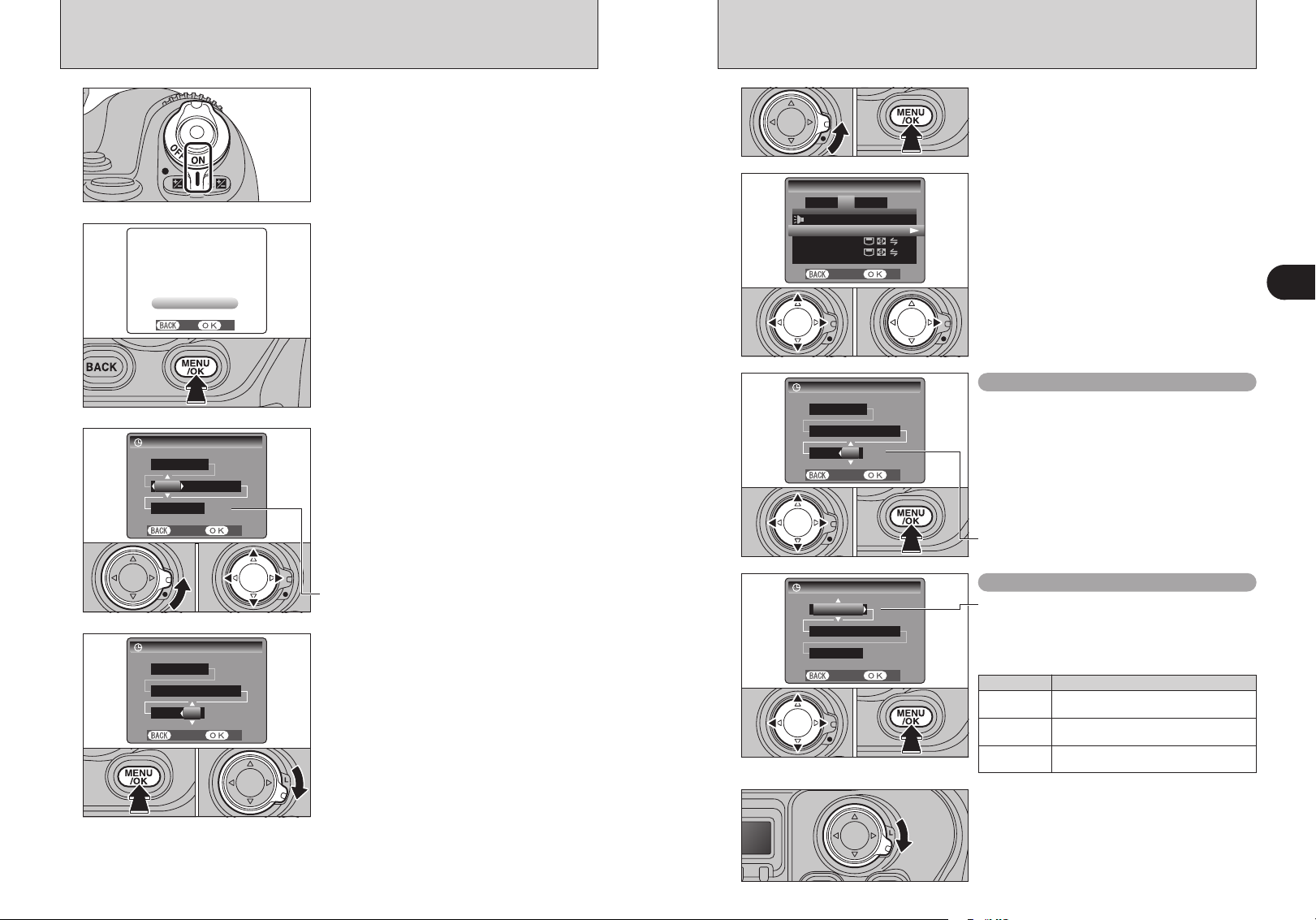
To turn the camera on, set the Power switch to
“ON”.
To turn the camera off, set the Power switch to
“OFF”.
After purchasing the camera, first time when
turning camera on, the date and time are cleared.
Press the “MENU/OK” button to set the date and
time.
01 02
1
2
1Unlock the 4-direction button.
2Press the “MENU/OK” button.
1Press “d” or “c” to move to option 3 and then
press “a” or “b” to select “DATE/TIME”.
2Press “c”.
01 02
!
If the message (see figure at left) does not appear, refer to
●
“Correcting the date and time” (➡P.27) and check and correct
the date and time settings.
!
The message also appears when the batteries have been
●
removed and the camera has been left for a long period.
!
To set the date and time later, press the “BACK” button.
3
●
!
If you do not set the date and time, this message will appear
●
each time you turn the camera on.
1Unlock the 4-direction button.
2Press “d” or “c” to select Year, Month, Day,
Hour or Minute and then press “a” or “b” to
adjust the selected setting.
3
Correcting the date and time
1Press “d” or “c” to select Year, Month, Day,
Hour or Minute.
2Press “a” or “b” to correct the setting.
3Always press the “MENU/OK” button after the
settings are completed.
01 02 03
!
Holding down “a” or “b” changes the numbers continuously.
●
!
When the time displayed passes “12:00”, the AM/PM setting
●
01 02
!
Holding down “a” or “b” changes the numbers continuously.
●
!
When the time displayed passes “12:00”, the AM/PM setting
●
changes.
1Once you have set the date and time, press the
4
01 02
26 27
“MENU/OK” button.
2
When you have finished the procedure, lock
the 4-direction button to prevent accidental
improper use.
!
At the time of purchase and after leaving the camera for a
●
long period with the batteries removed, settings such as the
date and time are cleared. Once the AC power adapter has
been connected or the batteries have been loaded for 2 days
or more, the date and time settings will be retained for
roughly 6 months even when the camera has no power
(batteries removed and AC power adapter disconnected).
01 02 03
4
changes.
Changing the date order
1Press “d” or “c” to select the date order.
2Press “a” or “b” to set the order. Refer to the
table below for details of the settings.
3Always press the “MENU/OK” button after the
settings are completed.
Date order Explanation
YYYY.MM.DD
MM/DD/YYYY
DD.MM.YYYY
When you have finished the procedure, lock the 4direction button to prevent accidental improper use.
Displays the date in the “year. month. day”
format.
Displays the date in the “month / day / year”
format.
Displays the date in the “day. month. year”
format.
1
Getting Ready
SELECTING THE LANGUAGE DIOPTER ADJUSTMENT / LCD ILLUMINATOR
言語言語
/LANG. ENGLISH/LANG. ENGLIS H
SET−UPSET−UP
VIDEO SYSTEM :NTSCVIDEO SYS TEM :NT SC
DISCHARGE :OKDISCHARGE :OK
21
3
4
5
FRAME NO. :CONT.
FRAME NO. :CO NT.
SETSET
CANCELCANCEL
01 02
1
01 02
2
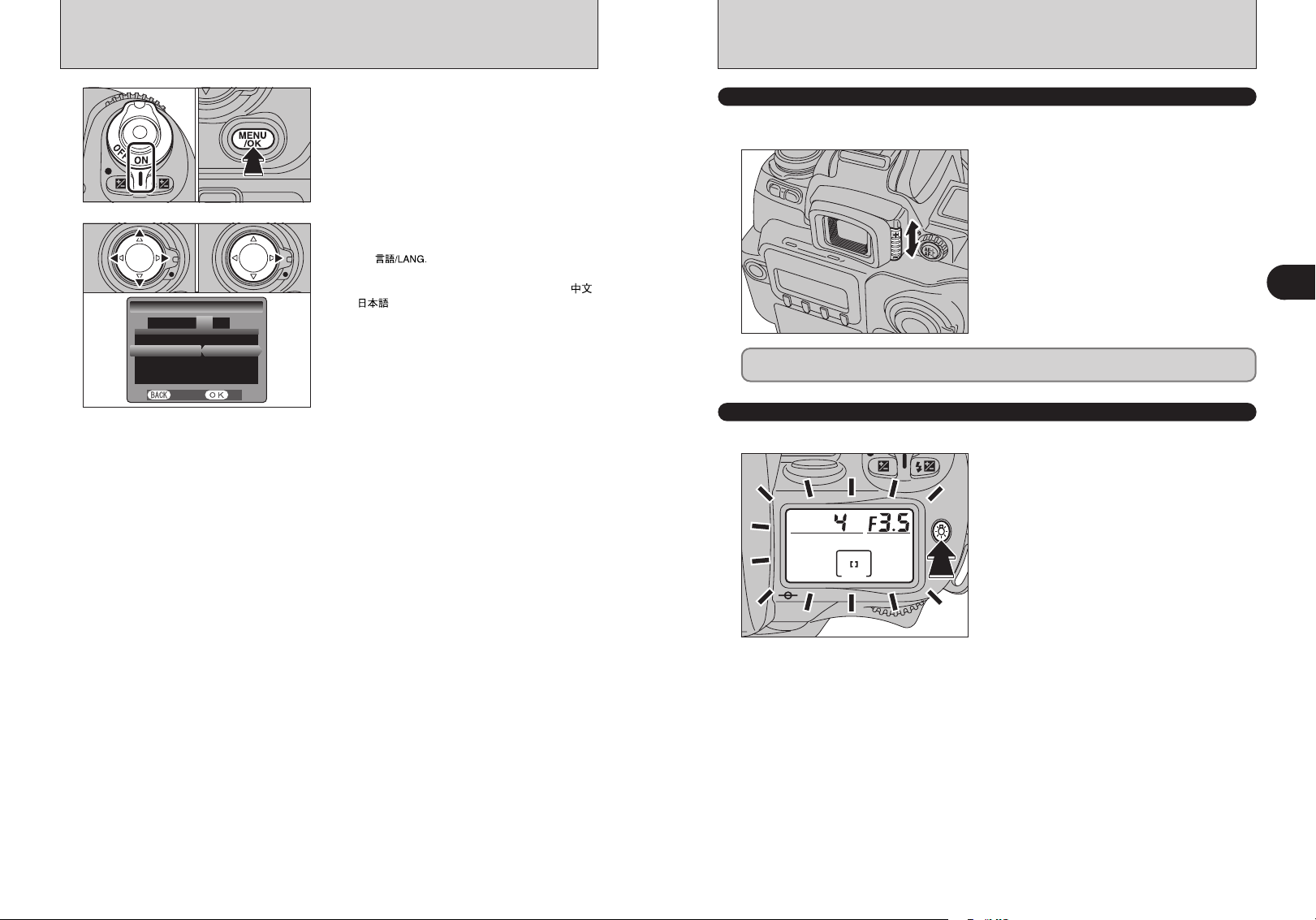
1Turn the camera on.
2Press the “MENU/OK” button to display the SET-
UP screen.
1The “SET-UP” screen appears. Press “d” or “c”
to move to option 4 and then press “a” or “b” to
select “ ”.
2Press “c” to select “ENGLISH”, “FRANCAIS”,
“DEUTSCH”, “ESPAÑOL”, “ITALIANO”, “ ”
or “ ”. Press “c ” to cycle through the
language settings.
!
The screens in this manual are shown in English.
●
!
See P.102 for more information on the “SET-UP” menu.
●
DIOPTER ADJUSTMENT
The finder diopter enables near- or far-sighted photographers to adjust the eyepiece diopter to suit
their vision.
While looking through the viewfinder, adjust the
position of the diopter adjustment knob until the
focusing frame or the image in the viewfinder
appears sharpest.
h The diopter setting can be adjusted from –2.0 m
(shortsighted) to +1.0 m-1(farsighted). Nikon also
provides 9 types of diopter adjustment lens
ranging from –5 m-1to +3 m-1.
Since the diopter adjustment knob is located next to the viewfinder, be careful not to poke yourself
in the eye with your finger or fingernail while sliding the knob.
LCD ILLUMINATOR
Displays in the top and rear display panels can be confirmed in the dark with the LCD illuminator.
When you press the “m” LCD illuminator button,
the top and rear display panels light up.
h Display panel illumination turns off in the
following situations:
i When you press the “
button again
i When you release the shutter
i When the Auto Power Off function turns the
camera off
m” LCD illumination
-1
1
Getting Ready
!
Pressing the shutter button down halfway temporarily turns
●
display panel illumination off.
CSM 14: The illuminator can be set to come on when any button is pressed (➡P.112).
28 29
Basic
2
Photography
BASIC OPERATION GUIDE
xPower switch
Turns the camera on
and off.
xRelease mode
switch unlock
button
Hold down this button
to move the release
mode switch.
xAccessory shoe
Mount an external flash here.
xFocus mode selector switch
Selects AF-S (Single-AF servo), AF-C
(Continuous-AF servo) or M (Manual)
as the focus mode.
xExposure mode dial
Allows you to select the exposure
mode, the custom settings and
the ISO setting,
: Programmed Auto
: Shutter-priority Auto
: Aperture-priority Auto
: Manual
: Custom settings
: ISO setting (sensitivity)
xFlash pop-up button
To use the built-in flash, press
this button to pop-up the flash.
xLens release button
Hold down this button as
you remove the lens.
xSynchronizing terminal
Use this to connect flash units
that require a synchro cord.
xRemote release socket
Used to connect a 10-pin
remote release.
xTop display panel
Displays the information
shown in the viewfinder
along with other information.
xDepth of field check
button
This button allows you to
check the depth of field.
xSub-command dial
Changes the aperture and other
settings.
xShutter button
Press this button down halfway to
restore the camera to
Photography mode. Press down
fully to take a picture.
xExposure compensation
button
Used with the Main-command
dial to select the exposure
compensation value.
xLCD illuminator button
Illuminates the display panel.
xFlash exposure
compensation button
Used with the Main-command dial
to select the flash exposure
compensation value.
xAuto exposure bracketing button
Used with the camera dials to select Auto Exposure Bracketing.
Main-command dial: Turns Auto Exposure Bracketing ON and OFF.
Sub-command dial: Selects a combination of exposure offset and number of shots.
xSynchro mode button
Used with the Main-command
dial to select Synchro mode.
xDiopter adjustment knob
Makes the image in the viewfinder easier to see.
Set this knob to the position where the focusing
area appears sharpest.
2
Basic Photography
xMetering system selector dial
Selects Multi, Center-weighted or Spot
as the metering system.
xRelease mode switch
Selects Single-frame, Continuous, Self-timer or Multi
Exposure as the shutter release mode.
xMain command dial
Changes settings such as the
shutter speed.
xAE-L / AF-L button
Locks the exposure and focus while
pressed.
30 31
BASIC OPERATION GUIDE
Main
SET−UP
IMAGE DISP . OFF
CUSTOM WB :SET
COLOR SPAC ES :sRGB
D−RANGE :WIDE
SET
CANCEL
ERASE
ALL FRAMES
BACK
Slower
Faster
Main
Sub
+
Main
+
Open
Close
Sub
xFUNC button
Selects the information displayed
on the rear display panel.
xRear display panel
Displays information during
shooting or playback.
x F1 to F4 buttons
Use these buttons to select items in the rear display panel.
x4-direction button
Use this button to select menu
options or the focus area.
x4-direction button lock
switch
Release this switch to use the
4-direction button.
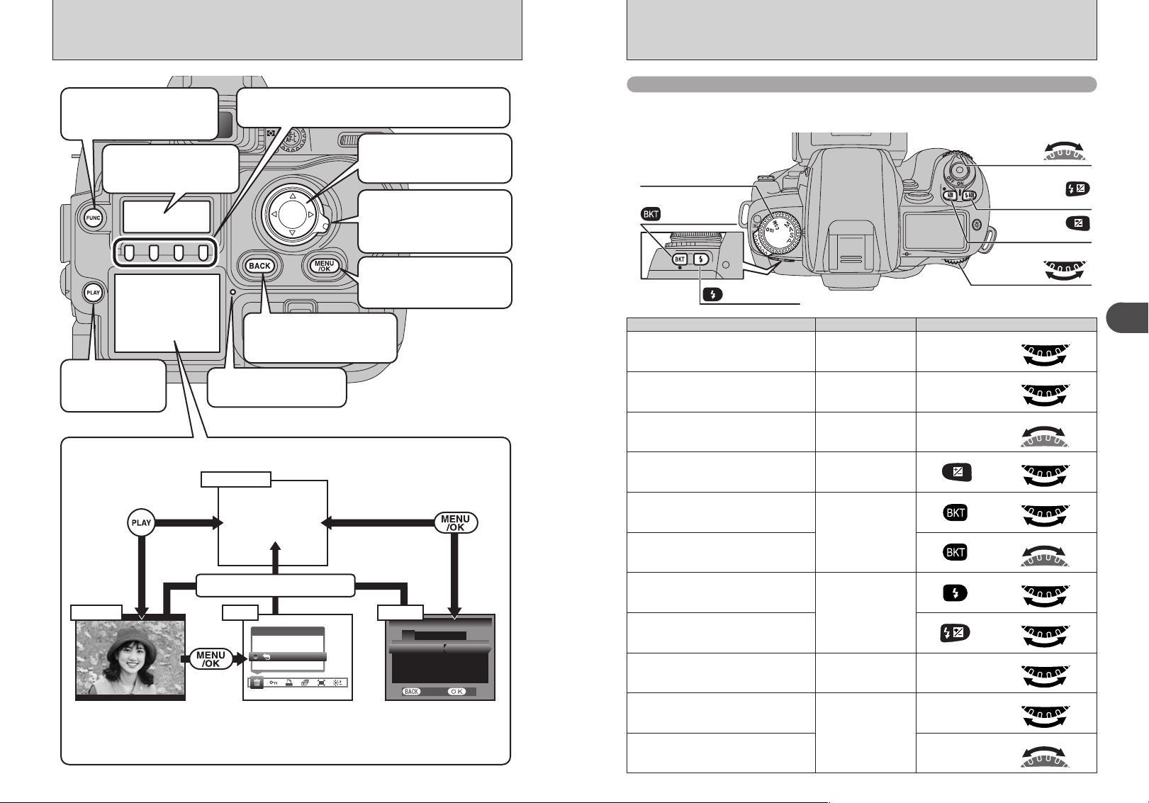
Command dials
The FinePix S3 Pro’s Main- and Sub-command dials are used alone or in combination with
other buttons to select/set various functions or modes.
Exposure mode dial
Auto Exposure
Bracketing button
Sub-command
dial
Flash exposure
compensation
button
Exposure
compensation
button
Main-
command dial
Procedure
xBACK button
xMENU/OK button
Press this button to confirm an
action in the menu screen.
Synchro mode
button
Setting
Exposure mode setting
Press this button to cancel an
action in the menu screen.
xPLAY button
Switches playback
display on and off.
x Access lamp
Lights during media access.
xPlayback, Menu and SET–UP Operations
Photography
LCD monitor
OFF
Shutter button pressed halfway
Menu SET-UPPlayback
ERASE
Frame advance : dc
Playback zoom : ab
ALL FRAMES
BACK
1Menu option selection : dc
2Setting selection : ab
3Confirmation : MENU/OK
Cancel : BACK
32 33
SET−UP
213 4 5
IMAGE DISP. OFF
CUSTOM WB :SET
COLOR SPACES :sRGB
D−RANGE :WIDE
CANCEL
1Option selection : ab
2Setting selection : dc
SET
Program shift “P”
Shutter speed setting “S, M”
Aperture setting “A, M”
Exposure compensation amount “P, S, A, M”
Auto Exposure Bracketing ON/OFF
“P, S, A, M”
Number of shots and exposure offset for Auto
Exposure Bracketing
Synchro mode setting
“P, S, A, M”
Flash exposure compensation amount
Sensitivity setting “ISO”
Custom setting option selection
“CSM”
Custom setting option modification
Main
+
Main
+
Main
+
Main
Main
Sub
2
Basic Photography

TAKING PICTURES (P Auto-Multi Program
)
1
01
2
02
01 02
3
Single
Area AF
Dynamic
AF
Set the focus mode selector switch to “S” (SingleAF Servo).
!
Make sure to turn the focus mode selector switch until it
●
clicks into position.
1Press the “FUNC” button to display the AF
setting on the rear display panel.
2Press the “F1” button to select “7” Single area
AF.
1Unlock the 4-direction button.
2Press “d ”, “c ”, “a” or “b ” to position the
focusing area in the center.
6
7
8
Set the metering system selector dial to “/”
(Matrix metering).
!
Matrix metering indication “l” appears in the viewfinder.
●
Set the Exposure mode dial to “P” (Auto-Multi
Program).
Brace your elbows against your body and hold the
camera with both hands.
2
Basic Photography
!
When shooting with the camera held vertically, see the
!
The selected focus area indicator appears on the top display
●
panel, in the viewfinder display and on the viewfinder screen
(➡P.47).
Lock the 4-direction button to prevent accidental
4
5
improper use.
Hold down the release mode switch unlock button
and set the release mode switch to “,” (Singleframe).
9
34 35
●
section on vertical shooting (➡P.36).
!
Take care not to obscure the lens with your fingers or the
●
shoulder strap.
Position the central focus area over the subject.
!
If the subject is outside the focus area, either move the focus
●
area or take the picture using the AF Lock function (➡P.40).
Continued
TAKING PICTURES (P Auto-Multi Program
ISO200
09 / 23 / 2004
10 : 00 AM
Shutter button for
vertical shooting
Lock lever for
vertical shooting
)
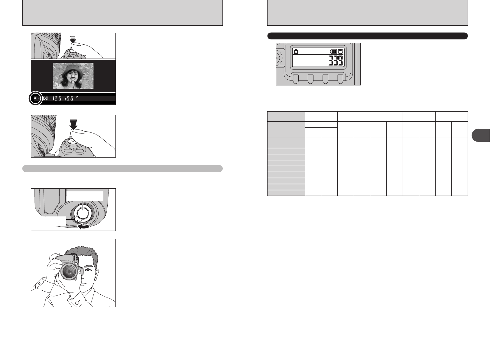
Press the shutter button down halfway to focus the
10
shot. The focus indicator “● ” appears in the
viewfinder display.
!
If the focus indicator is flashing, the camera cannot focus and
●
the shutter will not release.
Without releasing the shutter button, press it down
11
Shooting with the camera held on end (vertically
all the way (fully pressed) to take the shot.
)
The shutter button for vertical shooting makes taking pictures in this mode as convenient as normal
shooting.
Unlock the shutter button for vertical shooting.
1
NUMBER OF AVAILABLE SHOTS
The number of available shots is displayed on the
rear display panel.
!
See P.78-79 for information on changing the number of
●
recorded pixels/Quality (compression ratio) setting.
!
The factory default settings set at shipment are 6M and N
●
(Quality: NORMAL).
■ Standard number of shots for the media
Because the amount of data needed to record an image varies slightly depending on the type of subject, the number of
available shots may not decrease after an image is recorded, or may decrease by 2 in some cases. Also, the difference
between the standard number of shots and the actual number of available shots increases for media with a higher capacity.
Number of recorded
pixels
Quality Mode
Image File Size
DPC-16 (16 MB)
DPC-32 (32 MB)
DPC-64 (64 MB)
DPC-128 (128 MB)
DPC-256 (256 MB)
DPC-512 (512 MB)
Microdrive (340 MB)
Microdrive (1 GB)
CCD-RAW
`
HIGH
D-RANGE
D-RANGE
WIDE
STANDARD
Approx.
Approx.
25 MB
13 MB
01
12
24
59
10 19
20 39
13 27
41 81
4256 × 2848
4
FINE
NORMAL
Approx.
Approx.
4.7 MB
2.4 MB
3
6
6
13
13
26
26
53
53
107
107
214
73 146 116 232 200 396 338 671
220 437
3024 × 2016
3
FINE
NORMAL
Approx.
Approx.
3.0 MB
1.5 MB
5
10
10
20
21
42
42
84
85
169
170
339
349 698 597 1173 995 1932
✽ Number of available shots for formatted media.
2
FINE
Approx.
1.7 MB
8
17
36
72
146
292
2304 × 1536
NORMAL
Approx.
880 KB
17
35
72
144
290
580
1
FINE
Approx.
1 MB
14
30
61
122
245
491
1440 × 960
NORMAL
Approx.
520 KB
29
59
120
241
484
967
2
Basic Photography
Hold the camera vertically to take the picture.
2
!
When you are not using the shutter button for vertical
●
shooting, engage the lock lever for vertical shooting to
prevent the shutter button from being pressed by mistake.
!
Auto Power Off cannot be cancelled using the shutter button
●
for vertical shooting. Press the shutter button on the top of
36 37
the camera to restore power to the camera.
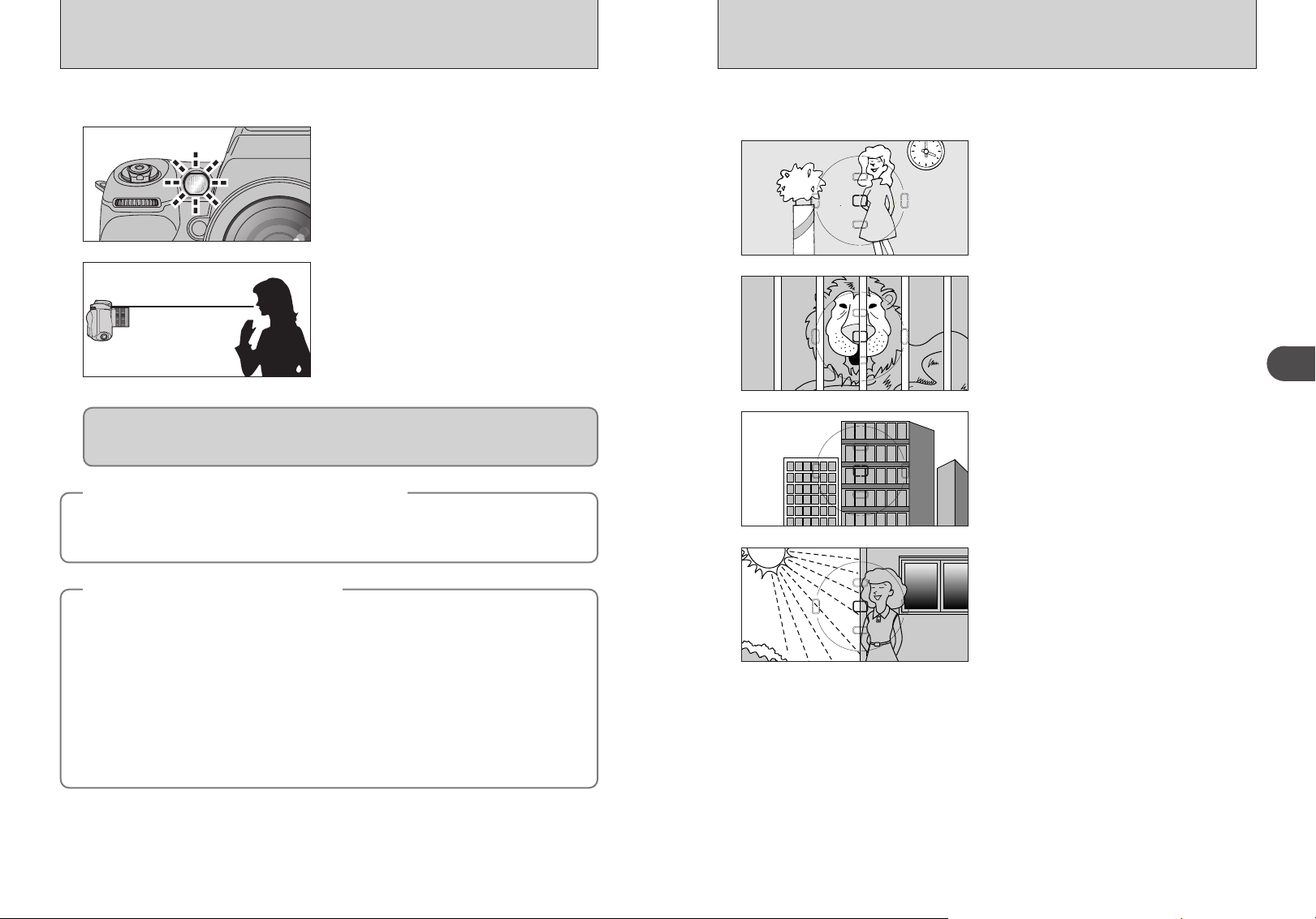
AF-ASSIST ILLUMINATOR
SITUATIONS WHERE AUTOFOCUS MAY NOT WORK AS EXPECTED
When the subject is dark and the shutter button is pressed down halfway, the camera’s AF-assist
illuminator automatically turns on and enables autofocus operation in a dark environment.
AF-assist illuminator automatically turns on in the
following situations:
Focus mode is Single AF servo, AF Nikkor lens is
used, subject is dark and center focus area is
selected or Dynamic AF Mode with Closest Subject
Priority is activated.
Focal length of the usable AF Nikkor lens is 24-200
mm and the distance range of the AF-assist
illuminator is approx. 0.5-3 m (1.6-9.8 ft.).
Approx. 0.5-3 m
(1.6-9.8 ft.)
CSM 15: AF-assist illuminator can be cancelled (➡P.112).
When the AF-assist illuminator is used continuously, illumination is limited temporarily to protect
the firing tube. The illumination restarts after a few moments. Also, when the AF-assist illuminator
is used repeatedly in a short period of time, be careful not to touch the AF-assist illuminator lamp
because it may have become hot.
Nikon flash units and active assist illuminator
◆
If you use an SB-28/28DX, SB-27, SB-26, SB-25, SB-24, SB-800 or SB-600 Nikon flash to take
pictures when the conditions for active assist illuminator are met, the active assist illuminator on the
Nikon flash automatically fires. With other Nikon flash models, the AF-assist illuminator on the camera
automatically lights.
Lenses for which vignetting occurs
◆
h Autofocus using the camera’s AF-assist illuminator cannot be performed due to vignetting with
following lenses at shooting distance within 1m (3.3 ft):
i AF Micro 200 mm f/4 IF-ED i AF 24-120 mm f/3.5-5.6 IF
i AF-S 17-35 mm f/2.8 IF-ED i AF-S 28-70 mm f/2.8 IF-ED
i AF 18-35 mm f/3.5-4.5 ED i AF Micro 70-180 mm f/4.5-5.6 ED
i AF 20-35 mm f/2.8 IF i AF 24-85 mm f/2.8-4
i AF 24-85mm f/2.8-4D i AF-S DX ED 12-24mm f/4G
i AF-S DX 18-70mm f/3.5-4.5G i AF-S ED 24-85mm f/3.5-4.5G
i AF-S VR ED 24-120mm f/3.5-5.6G i AF ED 28-200mm f/3.5-5.6G
h At shooting distances of 2 meters or less, the AF-S DX ED 17-55mm f/2.8G (IF) cannot be used for
autofocus photography where the AF-assist illuminator is used.
h Autofocus using the camera’s AF-assist illuminator cannot be performed due to vignetting with AF-S
80-200 mm f/2.8 IF-ED, AF 80-200 mm f/2.8 ED, AF VR 80-400 mm f/4.5-5.6 ED, AF-S VR ED 70200mm f/2.8D and AF-S VR ED 200-400mm f/4G.
◆
◆
Autofocus may not work as expected in the following situations. In such situations, focus manually
using the clear matte field or focus on a different subject located at the same distance, use AF lock
(➡P.40) then recompose.
Low-contrast scenes
For example, where the subject is wearing clothing
the same color as a wall or other background.
Scenes with subjects within the focus brackets
located at different distances from the camera
For example, when shooting an animal in a cage or
a person in a forest.
Patterned subject or scene
For example, building windows.
Scenes with pronounced differences in brightness
within the focus brackets
For example, when the sun is in the background
and the main subject is in shadow.
2
Basic Photography
38 39
Center-weighted metering
Spot metering
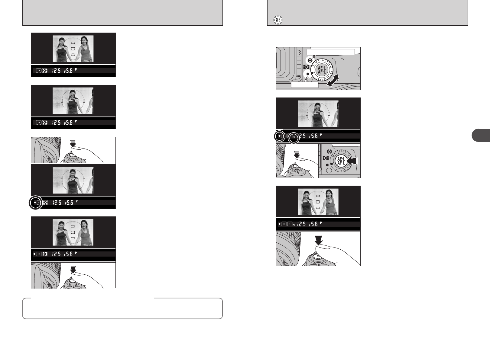
USING AF LOCK
TAKING PICTURES WITH AE LOCK
If you take a shot with this type of composition
1
2
3
4
When AF (Auto Focus) does not focus the shot
◆
h Position the focus area over another subject at roughly the same distance and press the shutter
button down halfway. Then recompose the shot and take the picture.
h You can also set the focus and take the shot by selecting “M” (manual) as the focus mode.
using Single-area AF with the focus area in the
center, the subjects (the two people in this case)
are outside the focus area and will not be in focus.
Move the camera slightly so that one of the
subjects is in the AF frame.
Keep the shutter button pressed down halfway (AF
lock) and check that the focus indicator “●” is lit in
the viewfinder display.
!
If you are using the “AF-C” focus mode, hold the shutter
●
button down halfway and press the “AE-L/AF-L” button
(➡P.41).
Continue to hold the shutter button down halfway
(AF lock). Move the camera back to the original
image and then fully press down on the shutter
button.
!
You can reapply the AF lock as many times as you like
●
before releasing the shutter.
!
The AF lock operates in all photography modes and can be
●
used to ensure excellent results.
◆
AE lock allows you to set the exposure for a specific subject in your shot. This technique is useful
when brightness of your subject differs greatly from its surroundings.
Set the metering system selector dial to “-”
1
2
3
CSM 5: Auto Exposure Lock can be set to be activated by pressing the shutter button down
halfway (➡P.111).
CSM 9: The operation performed when the “AE-L/AF-L” button is pressed can be modified
(➡P.111).
Operation: AF/AE lock (default setting), AE lock only, AF lock only, AE lock maintained, AF
operation
Center-weighted or “0” Spot metering.
h Matrix metering is not recommended since the
effect of the Auto Exposure Lock cannot be
effectively attained.
Position the focus area over the subject you want
correctly exposed, press and hold the shutter
button down halfway and then press the “AE-L/AFL” button. The “EL” (exposure lock) indicator
appears in the viewfinder.
h The exposure and focus are locked as long as
the “AE-L/AF-L” button is held down (default
setting).
h If you press the “AE-L/AF-L” button in the “AF-S”
or “AF-C” focus mode when the shot is not in
focus, the exposure is locked with the shot out of
focus. Always check that the focus indicator “●”
is lit.
While keeping the “AE-L/AF-L” button pressed,
recompose, focus and shoot.
h Because the settings are maintained after you
take the shot for as long as the “AE-L/AF-L”
button is held down, you can keep the same
settings as you recompose the shot.
h The following functions can be operated while the
“AE-L/AF-L” button is kept pressed:
1. In “P” exposure mode: Sets program shift.
2. In “S” exposure mode: Changes the shutter
speed.
3. In “A” exposure mode: Changes the aperture.
h Rotating the metering system selector to another
setting does not change the metering system
during Auto Exposure Lock operation. Release
the AE lock.
2
Basic Photography
40 41
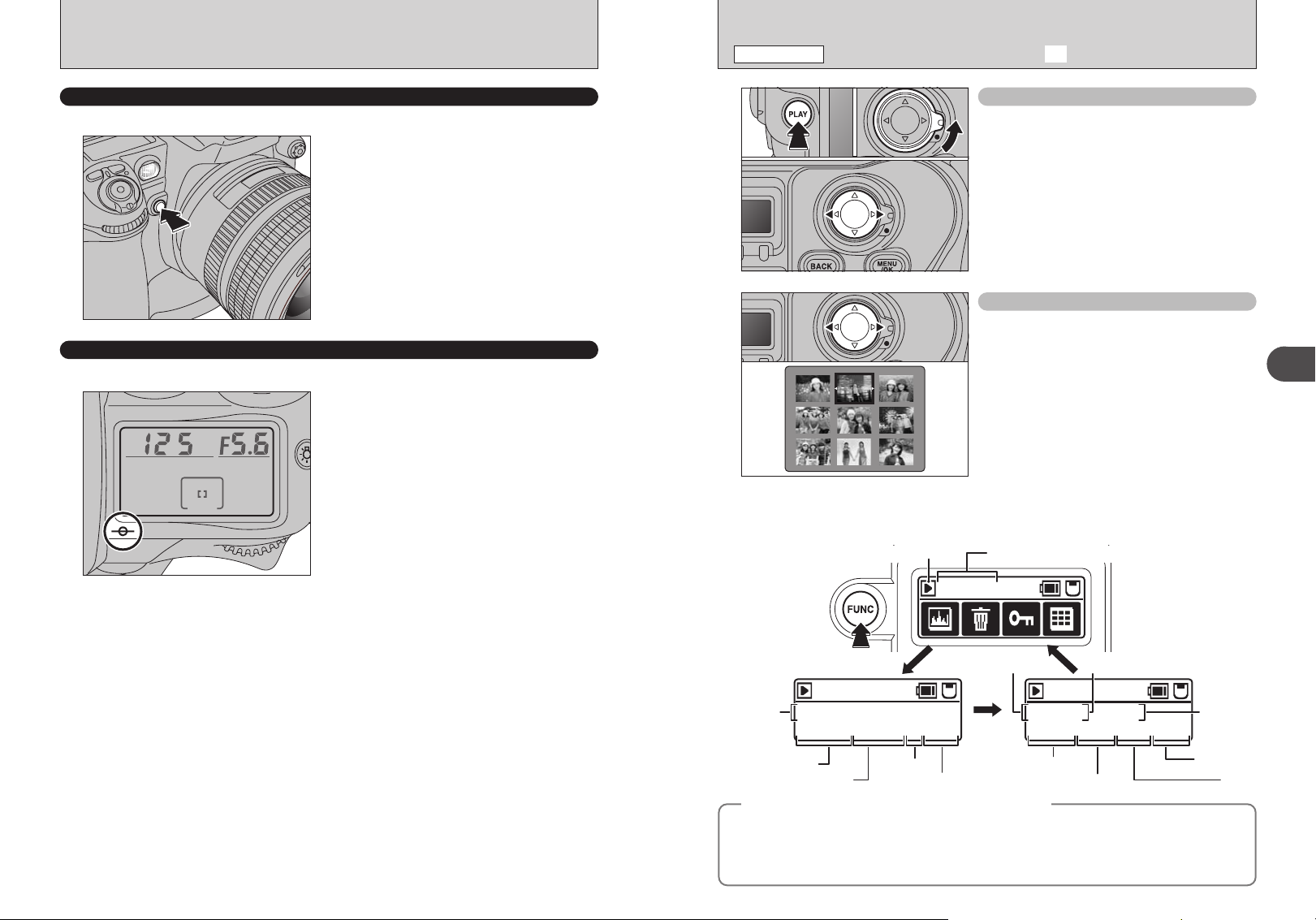
DEPTH OF FIELD CHECK BUTTON / CCD PLANE INDICATOR
PLAYBACK MODE
VIEWING THE IMAGES (w PLAYBACK
)
DEPTH OF FIELD CHECK BUTTON
Depress the depth of field check button to confirm the depth of field through the viewfinder.
Pressing the depth of field check button stops the
lens down to the aperture controlled in “P” AutoMulti Program or “S” Shutter-Priority Auto exposure
mode, and down to the aperture selected in “A”
Aperture-Priority Auto or “M” Manual exposure
mode. By looking through the viewfinder, the
approximate depth of field with the given aperture
can be confirmed.
!
When you press the depth of field check button, the shutter
●
speed display and LCD illumination both turn off.
CCD PLANE INDICATOR
The CCD plane indicator shows the position of the CCD plane inside the camera body.
The CCD plane indicator shows the standard line of
the shooting distance and indicates the position of
the CCD plane inside the camera body. Use this
indicator when actually measuring camera-tosubject distance, e.g. in close-up photography. The
exact distance from the lens mounting flange to the
CCD plane is 46.5 mm.
01 02
03
Single-frame playback
1Press the “PLAY” button to view your images.
2Unlock the 4-direction button.
3Press “c” to scan forward through your images.
Press “d” to scan backwards.
!
Pressing the “PLAY” button displays the last image
●
photographed.
Selecting images
To select images on the thumbnail lists screen,
hold down “d” or “c” for approx. 1 second during
playback.
■ Displaying the photography data
Press the “FUNC” button during image playback to check the photography data for the currently
displayed frame.
Playback mode Frame number
2
Basic Photography
Press the “FUNC”
button to switch
between
functions.
100-0009
Date /
09 / 23 / 2004 10 : 00 AM
Time
WB:AUTO NORMAL 6M F:STD
White balance
Quality
Still images viewable on the FinePix S3 Pro
◆
This camera will display still images recorded on the FinePix S3 Pro or still images (excluding some
uncompressed images) recorded on any FUJIFILM digital camera that supports xD-Picture Cards or
CF/Microdrives.
Clear playback or playback zooming may not be possible for still images shot on cameras other than
42 43
the FinePix S3 Pro.
Recorded
pixels
100-0009
Shutter speed Aperture
Film simulation
100-0009
125 F5.6 ISO200
STD S:STD
:
T
D:AUTO C:STD
Dynamic range
◆
Sensitivity
Sharpness
To neColor
 Loading...