

DIGITAL CAMERA
S3100
FinePix S3500
SERVICE MANUAL
US/CA/EU/EG/GE/AS-Model
WARNING
THE COMPONENTS IDENTIFIED BY THE MARK “ ” ON THE SCHEMATIC
DIAGRAM AND IN THE PARTS LIST ARE CRITICAL FOR SAFETY.
PLEASE REPLACE ONLY BY THE COMPONENTS SPECIFIED ON THE SCHEMATIC
DIAGRAM AND IN THE PARTS LIST.
IF YOU USE PARTS NOT SPECIFIED, IT MAY RESULT IN A FIRE AND AN
ELECTRICAL SHOCK.
FUJI PHOTO FILM CO., LTD.
Ref.No.:ZM00552-101
Printed in Japan 2005.10
SAFETY CHECK-OUT
After correcting the original problem, perform the following
safety check before return the product to the costomer.
Fine Pix S3100/S3500 SERVICE MANUAL
1. Check the area of your repair for unsoldered or poorly
sol dered connections. Check the entire board sur-
face for solder splasher and bridges.
2. Check the interboard wiring to ensure that no wires
are “pinched” or contact high-wattage resistors.
3. Look for unauthorized replacement parts, particuarly
tran sistors, that were installed during a previous re-
pair. Point them out to the customer and recommend
their replacement.
4. Look for parts which, though functioning, show ob-
vious signs of deterioration. Point them out to the
customer and recommend their replacement.
5. Check the B + voltage to see it is at the values speci-
fied.
6. Make leakage - current measurements to determine
that exposed parts are acceptably insulated from the
supply circuit before returning the product to the cus-
tomer.
7. CAUTION: FOR CONTINUED PRO-
TECTION AGAINST FIRE HAZARD,
REPLACE ONLY WITH SAME TYPE
2.5 AMPERES 125V FUSE.
2.5A 125V
2.5A 125V
RISK OF FIREREPLACE FUSE
AS MARKED
ATTENTION: AFIN D'ASSURER
UNEPROTECTION PERMANENTE
CONTRE LES RISQUES D'INCENDIE,
REMPLACER UNIQUEMENT PAR UN
FUSIBLE DE MEME, TYPE 2.5 AM-
PERES, 125 VOLTS.
8.
WARNING!
HIGH VOLTAGE
WARNING:
TO REDUCE THE ELECTRIC SHOCK,
BE CAREFUL TO TOUCH THE PARTS.
2

Fine Pix S3100/S3500 SERVICE MANUAL
TABLE OF CONTENTS
1. General ............................................................ 4
1-1. Product specification ............................................... 4
1-2. Explanation of Terms ............................................... 6
1-3. Names of External Components.............................. 7
2. Disassembly .................................................... 8
2-1. Names of Internal Parts ........................................... 8
2-2. How to Disassemble the CABI R ASSY .................. 9
2-3. Removing LCD ASSY / LCD FRAME .................... 10
2-4. Removing EVF CONST ......................................... 11
2-5. Removing MAIN PWB ASSY................................. 11
2-6. Removing BATTERY HOLDER ASSY................... 11
2-7. Removing DCST PWB ASSY ................................12
2-8. Removing LENS CONST ...................................... 12
2-9. Removing STROBE CONST/ST TOP ................... 13
2-10. Removing MSW PWB ASSY and
RSW PWB ASSY .................................................. 14
2-11. Removing KEY PWB ASSY ................................... 14
2-12. Disassembly of LENS CONST ..............................15
2-13. Location of Sheet parts.......................................... 16
2-13-1. CCD EMI SHEET (FZ06017-100) .............16
2-13-2. GASKET USB (BB18395-100) .................. 16
2-13-3. LCD-EMI SHEET (FZ6000-100) ............... 16
2-13-4. LENS-EMI SHEET (FZ06018-100) ........... 17
2-13-5. EMI SHEET AF (FZ05587-100) ................ 17
3. Schematics.................................................... 19
3-1. Cautions ................................................................ 19
3-2. Names and Functions of Basic Blocks .................. 19
3-3. Explanation of Functions of Important Blocks ....... 20
3-4. Block Diagram ....................................................... 21
3-5. Overall ................................................................... 22
3-6. Mounted Parts Diagrams ....................................... 23
3-6-1. MAIN PWB ASSY Component Location ... 23
3-6-2. DCDC PWB ASSY Component Location .. 24
3-6-3. CCD PWB CONST Component Location . 25
3-6-4. MSW PWB UNIT Component Location .... 25
3-6-5. RSW PWB UNIT Component Location ..... 25
3-6-6. VCON PWB UNIT Component Location ... 26
3-6-7. KEY PWB UNIT Component Location ...... 26
3-7. Circuit Diagrams ....................................................27
3-7-1. DCDC Block Circuit ................................... 27
3-7-2. PROCESS Block Circuit ........................... 28
3-7-3. CAM Block Circuit ..................................... 29
3-7-4. IPS_STROBE Block Circuit ...................... 30
3-7-5. MOTOR Block Circuit ................................ 31
3-7-6. LCD Block Circuit ......................................32
3-7-7. CCD Block Circuit ..................................... 33
3-7-8. MSW Block Circuit .................................... 34
3-7-9. KSW Block Circuit .....................................34
3-7-10. VCON Block Circuit ................................... 35
3-7-11. RSW Block Circuit ..................................... 35
4. Adjustment .................................................... 36
4-1. Important point Adjustment when Replacing Major
Parts ...................................................................... 36
4-2. Measuring Instruments Used................................. 36
4-3. Use Jig list ............................................................. 36
4-4. Calibration method of pattern box ......................... 37
4-5. Adjusting soft installation .......................................37
4-5-1. Various downloading software
decompressions, preservation methods,
and notes .................................................. 37
4-5-2. Installation of DSC jig driver ...................... 38
4-5-3. Adjusting soft initiation method ................. 38
4-6. Initial Settings of the Adjustment Software ...........39
4-7. Starting the Adjustment Software .......................... 42
4-8. [F5] : CAMERA Adjustment ................................... 45
4-9. [F4] CCD Defect Correction Adjustment................ 48
4-10. [F6] : AF Adjustment .............................................. 50
4-11. [F7] : Flash Adjustment .......................................... 52
4-12. [F1] : Battery Voltage Adjustment .......................... 54
4-13. [F11] : Video Adjustment ........................................ 58
4-14. [F3] : LCD Adjustment ........................................... 60
4-15. [F8] : Firmware Download ..................................... 62
4-16. [F12] : End Setting ................................................. 64
5. Inspection ...................................................... 68
5-1. Required Measuring Equipment ............................68
5-2. Connection of Measuring Equipment .................... 68
5-3. Inspection and Factory Settings ............................ 68
6. Parts list ......................................................... 70
6-1. Packing and Accessoris ........................................ 70
6-1-1. FinePix S3100 (US model) ....................... 70
6-1-2. FinePix S3100 (CA model) ........................ 71
6-1-3. FinePix S3500 (EU model) ....................... 72
6-1-4. FinePix S3500 (EG model) ....................... 73
6-1-5. FinePix S3500 (GE model) ....................... 74
6-1-6. FinePix S3500 (AS model) ........................ 75
6-2. Cabinet F block ..................................................... 76
6-2-1. FinePix S3100(US/CA model) ...................76
6-2-2. FinePix S3500(EU/EG/GE/AS model) ...... 77
6-3. Inner block .............................................................78
6-4. Cabinet R block ..................................................... 79
6-5. Electrical parts .......................................................80
7. Appendix ....................................................... 81
7-1. Version display function ......................................... 81
7-2. List of Related Technical Updates Issued .............. 82
3

1.General
Fine Pix S3100/S3500 SERVICE MANUAL
1.General
1-1.Product specification
System
Model Digital camera FinePix S3100 / FinePix S3500
Effective pixels 4.0 million pixels
CCD 1/2.7 inch square pixel CCD Number of total pixels: 4.23 million pixels
Number of recorded pixels
Storage media xD-Picture Card (16/32/64/128/256/512 MB)
File format Still image: JPEG (Exif ver. 2.2)
Lens Fujinon 6
Aperture F2.8 to F3.0 (automatically selected)
Focal length f=6.0 mm to 36 mm (Equivalent to 39 mm to 234 mm on a 35 mm camera)
Focal range Normal: Approx. 0.8 m (2.6 ft.) to infinity
Shutter speed 2 sec. to 1/1500 sec. (combined with mechanical shutter)
Focus TTL contrast-type, Auto focus
Sensitivity Equivalent to ISO 100 (automatically set between ISO 64 - 250 depend on the
Photometry TTL 64-zones metering
Exposure control Program AE
Exposure compensation
White balance Auto (
Viewfinder 0.33 inches 110,000 pixels electronic viewfinder
LCD monitor 1.5 inches, 60,000 pixels amorphous silicon TFT,
Flash type Auto flash using flash control sensor
Self-Timer 10 sec.
Video output NTSC/PAL selectable
Still image: 2272 × 1704 pixels/1600 × 1200 pixels/1280 × 960 pixels/
640
Movie: 320
160
×
480 pixels ( / / / )
×
240 pixels (10 frames per second without sound)
×
120 pixels (10 frames per second without sound)
* Design rule for Camera File System compliant DPOF compatible
Movie: AVI format, Motion JPEG
×
optical zoom lens, F2.8-F3.0
Macro: Approx. 0.1 m (3.9 in.) to 0.8 m (2.6 ft.)
shooting mode and subject.)
-2.1 EV to +1.5 EV in 0.3-step increments (in Manual mode)
), Scene position ( ) Manual modes, 7 positions can be selected
NTSC Approx. 88% coverage PAL Approx. 86% coverage
NTSC: Approx. 87% coverage, PAL: Approx. 85% coverage
Effective range:
Wide-angle: Approx. 0.8 m to 3.5 m (2.6 ft. to 11.5 ft.)
(Approx. 0.3 m to 0.8 m (1.0 ft. to 2.6 ft.): Macro)
Telephoto: Approx. 0.8 m to 3.5 m (2.6 ft. to 11.5 ft.)
Flash modes: Auto, Red-Eye Reduction, Forced Flash, Suppressed Flash, Slow
Synchro*, Red-Eye Reduction + Slow Synchro* * In Manual mode
Input/Output Terminals
Video output socket 2.5 mm dia. jack
(USB) socket For file transfer to a computer
DC Input Socket for specified AC power adapter AC-5VH/AC-5VHS (sold separately)
Standard number of available frames/recording time per xD-Picture Card
The number of available
that the difference between standard number of
xD-Picture Cards with higher capacities.
Quality Setting
Number of recorded pixels
Image Data Size
DPC-16 (16 MB)
DPC-32 (32 MB)
DPC-64 (64 MB)
DPC-128 (128 MB)
DPC-256 (256 MB)
DPC-512 (512 MB)
, recording time or file size varies slightly depending on the subjects photographed. Note also
frames
F N
2272
1704
1.9 MB 960 KB
8
16
33
66
134
268
frames
1600 1200
620 KB
16
32
66
132
266
532 818 1101
25
50
101
204
409
and the actual number of
1280
460 KB
33
68
137
275
550
960
640
480
125 KB
122
247
497
997
1997
3993 Approx. 53.5 min.
frames
Movie
320 240
Approx. 98 sec.
Approx. 199 sec.
Approx. 6.6 min.
Approx. 13.3 min.
Approx. 26.7 min.
is greater for
Movie
160 120
Approx. 5.6 min.
Approx. 11.3 min.
Approx. 22.7 min.
Approx. 45.5 min.
Approx. 91.2 min.
Approx. 182.5 min.
4

Fine Pix S3100/S3500 SERVICE MANUAL
Power Supply and Others
Power supply Use one of the following:
• 4×AA-size alkaline batteries
• 4×AA-size Ni-MH (Nickel-Metal Hydride) batteries (sold separately)
• AC Power Adapter AC-5VH/AC-5VHS (sold separately)
Guide to the number
of available frames
for battery operation
According to the Camera & Imaging Products Association (CIPA) standards*:
When using alkaline batteries, use the batteries supplied with the camera. When
using Ni-MH batteries, use Fujifilm Rechargeble Battery.
The storage media should be xD-Picture Card.
• Note: Because the number of available shots varies depending on the capacity of
* “CIPA DC-002-2003 ‘Standard Procedure for Measuring Digital Still Camera Bat-
tery Consumption’ ” (extract)
Pictures shall be taken at a temperature of 23
the zoom moved from full wide-angle to full telephoto (or vice-versa) and back
again to its original position every 30 seconds, the flash used at full power every
second shot and the camera turned off and then on again once every 10 shots.
Conditions for use Temperature: 0
Camera dimensions 99.7 mm × 77.3 mm × 69.3 mm/3.9 in. × 3.0 in. × 2.7 in.
(W/H/D) (not including accessories and attachments)
Camera mass (weight)
Weight for photography
Accessories z LR6 AA-size alkaline batteries (4)
Optional Accessories z xD-Picture Card
Approx. 285 g/10.1 oz.
(not including accessories, batteries, xD-Picture Card and Adapter Ring)
Approx. 410 g/14.5 oz. (including batteries and xD-Picture Card)
z 16MB, xD-Picture Card (1) Included with: Anti-static case (1)
z Shoulder strap (1)
z Video cable (1) (plug (2.5 mm dia. ) to pin-plug) Approx. 1.5 m (4.9 ft.)
z USB cable (1) z Lens cap (1) z Adapter ring (1)
z CD-ROM: Software for FinePix AX (1) z Owner’s Manual (1)
z AC Power Adapter AC-5VH/AC-5VHS z
z
Fujifilm Battery Charger with Battery BK-NH/BK-NH2 (With Euro type or UK type plug)
z Carrying Case SC-FX304
z Image Memory Card Reader DPC-R1
z PC Card Adapter DPC-AD
z CompactFlash Card Adapter DPC-CF
z xD-Picture Card USB Drive DPC-UD1
Alkaline batteries Ni-MH batteries (2300mAH)
Approx. 300 frames Approx. 500 frames
alkaline batteries or the level of charge in Ni-MH batteries, the figures
shown here for the number of available shots using batteries are not guaranteed.
The number of available shots will also decline at low temperatures.
o
C to +40oC (+32oF to +104oF); 80% humidity or less (no condensation)
DPC-16 (16 MB)/DPC-32 (32 MB)/DPC-64 (64 MB)/DPC-128 (128 MB)/
DPC-256 (256 MB)/DPC-512 (512 MB)
• Compatible with Windows 98/98 SE, Windows Me, Windows 2000 Professional, Windows XP or iMac, Mac OS 8.6 to 9.2.2, Mac OS X (10.1.2 to
10.2.2) and models that support USB as standard.
• Compatible with xD-Picture Cards of 16 MB to 512 MB, and SmartMedia of
3.3V, 4 MB to 128 MB.
• Compatible with xD-Picture Cards of 16 MB to 512 MB, and SmartMedia of
3.3V, 2 MB to 128 MB.
• Windows 95/98/98 SE/Me/2000 Professional/XP
• Mac OS 8.6 to 9.2/X (10.1.2 to 10.1.5)
• Compatible with xD-Picture Card of 16 MB to 512 MB
• Windows 98/98 SE/Me/2000 Professional/XP
• Mac OS 9.0 to 9.2/X (10.0.4 to 10.2.6)
Battery Type
o
C, with the LCD monitor turned on,
Fujifilm Rechargeable Battery 2HR-3UF
1.General
5

1.General
Fine Pix S3100/S3500 SERVICE MANUAL
1-2.Explanation of Terms
AF/AE Lock: On the FinePix S3100/FinePix S3500, pressing the shutter button down half way
locks the focus and exposure settings (AF and AE lock). If you want to focus on a
subject that is not centered in the frame or change the picture composition after the
exposure is set, you can obtain good results by changing the composition after the
AF and AE settings are locked.
Auto power save function:
Deactivated batteries: Leaving an Ni-MH battery unused in storage for a long period may cause a rise in
DPOF: Digital Print Order Format
EV: A number that denotes Exposure Value. The EV is determined by the brightness of
Frame rate (fps): The frame rate refers to the number of images (frames) that are photographed or
JPEG : Joint Photographics Experts Group
Memory effect: If an Ni-MH battery is repeatedly charged without first being fully discharged, its perfor-
Motion JPEG: A type of AVI (Audio Video Interleave) file format that handles images and sound as
PC Card: A generic term for cards that meet the PC Card Standard.
PC Card Standard: A standard for PC cards determined by the PCMCIA.
PCMCIA: Personal Computer Memory Card International Association (US).
Smear: A phenomenon specific to CCDs whereby white streaks appear on the image when
WAVE: A standard format used on Windows systems for saving audio data. WAVE files
White Balance: Whatever the kind of the light, the human eye adapts to it so that a white object still
Exif Print: Exif Print Format is a newly revised digital camera file format that contains a variety
If the camera is not used in any way for 60 seconds, this function turns features
such as the LCD monitor off (sleep mode) to prevent battery depletion and the
waste of power when the AC power adapter is connected. If the camera is then left
unused for a further period, the Auto power save function turns the camera off. This
period can be set to 2 minutes or 5 minutes on this camera.
z The Auto power off function does not operate in PC mode, during automatic
playback, or if it is disabled during setup.
the level of substances that inhibit current flow inside the battery and result in a
dormant battery. A battery in this state is referred to as deactivated.
Because current flow is inhibited in a deactivated Ni-MH battery, the battery’s original level of performance cannot be achieved.
DPOF is a format used for recording information on a storage media (image
memory card, etc.) that allows you to specify which of the frames shot using a
digital camera are to be printed and how many prints are made of each image.
the subject and sensitivity (speed) of the film or CCD. The number is larger for
bright subjects and smaller for dark subjects. As the brightness of the subject
changes, a digital camera maintains the amount of light hitting the CCD at a constant level by adjusting the aperture and shutter speed.
When the amount of light striking the CCD doubles, the EV increases by 1. Likewise, when the light is halved, the EV decreases by 1.
played back per second. For example, when 10 frames are continuously photographed in a 1-second interval, the frame rate is expressed as 10 fps.
For reference, TV images are displayed at 30 fps (NTSC).
A file format used for compressing and saving color images. The higher the compression rate, the greater the loss of quality in the decompressed (restored) image.
mance may drop below its original level. This is referred to as the “memory effect”.
a single file. Images in the file are recorded in JPEG format. Motion JPEG can be
played back by QuickTime 3.0 or later.
there is a very strong light source, such as the sun or reflected sunlight, in the
photography screen.
have the “.WAV” file extension and the data can be saved in either compressed or
uncompressed format. Uncompressed recording is used on this camera.
WAVE files can be played back on a personal computer using the following software:
Windows: MediaPlayer
Macintosh: QuickTime Player
* QuickTime 3.0 or later
looks white. On the other hand, devices such as digital cameras see a white subject
as white by first adjusting the color balance to suit the color of the ambient light
around the subject. This adjustment is called matching the white balance.
of shooting information for optimal printing.
6
Fine Pix S3100/S3500 SERVICE MANUAL
t
t
t
t
r
r
r
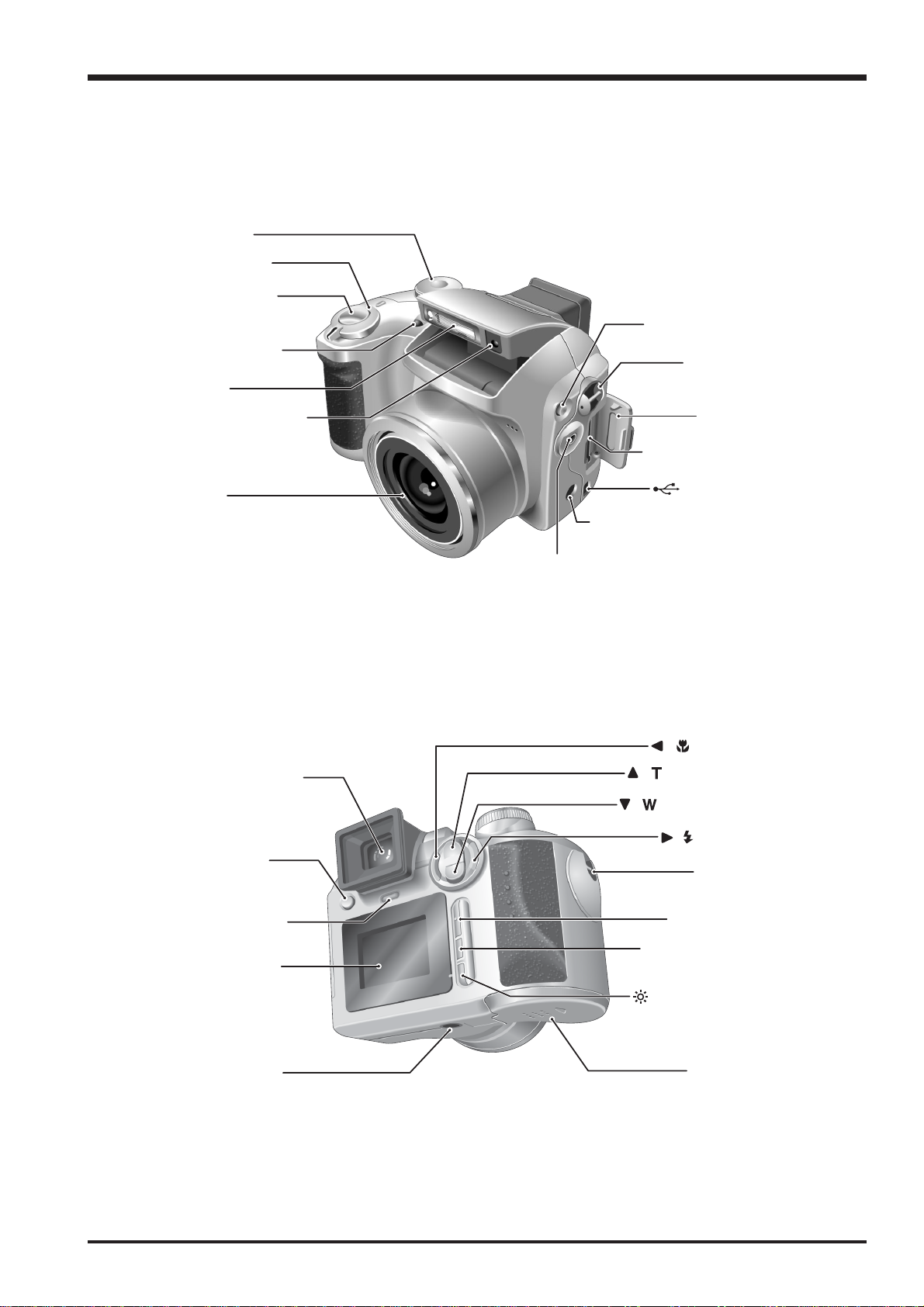
1-3.Names of External Components
Mode dial
Power switch
Shutter button
Self-timer lamp
Flash
1.General
Flash pop-up button
Strap moun
Flash control sensor
Lens
Viewfinder (EVF)
EVF / LCD
(monitor selector)
button
xD-Picture Card slo
DC IN 5V (power input) socke
VIDEO OUT (Video output) socket
/ Macro button
/ (Tele zoom) button
/ (Wide zoom) button
Slot cove
(USB) socke
/ Flash button
Strap mount
Indicator lamp
LCD monitor
Tripod mount
MENU/OK button
DISP (Display) / BACK
Low Light Viewfinde
button
button
Battery cove
7
2.Disassembly
2. Disassembly
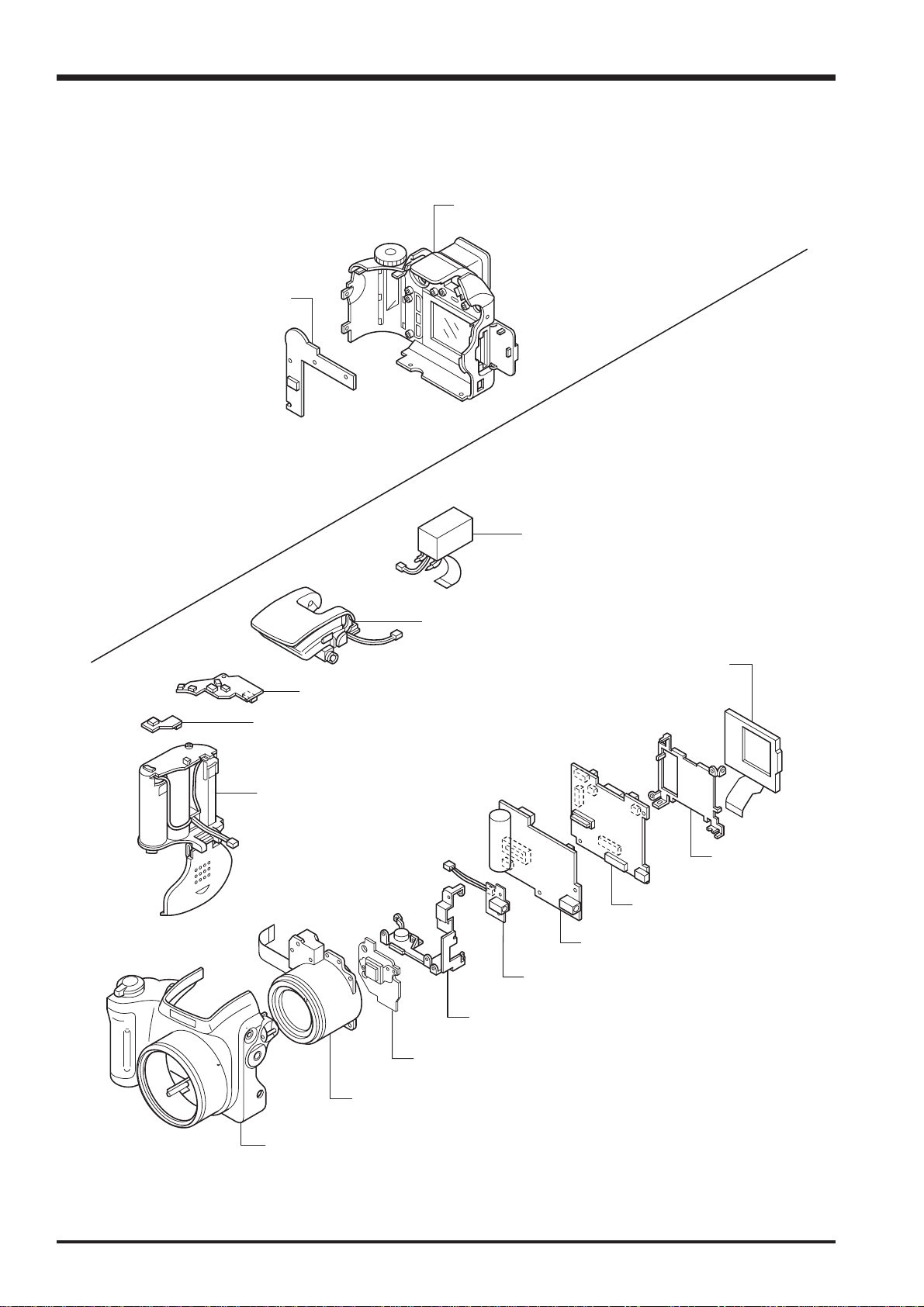
2-1.Names of Internal Parts
KEY PWB ASSY
Fine Pix S3100/S3500 SERVICE MANUAL
CABI REAR ASSY
STROBE CONST
MSW PWB ASSY
RSW PWB ASSY
BATTERY HOLDER ASSY
EVF CONST
LCD CONST
LCD FRAME
MAIN PWB ASSY
DCST PWB ASSY
VCON PWB ASSY
MAIN FRAME ASSY
CCD PWB CONST
LENS UNIT
CABI FRONT ASSY
8
Fine Pix S3100/S3500 SERVICE MANUAL
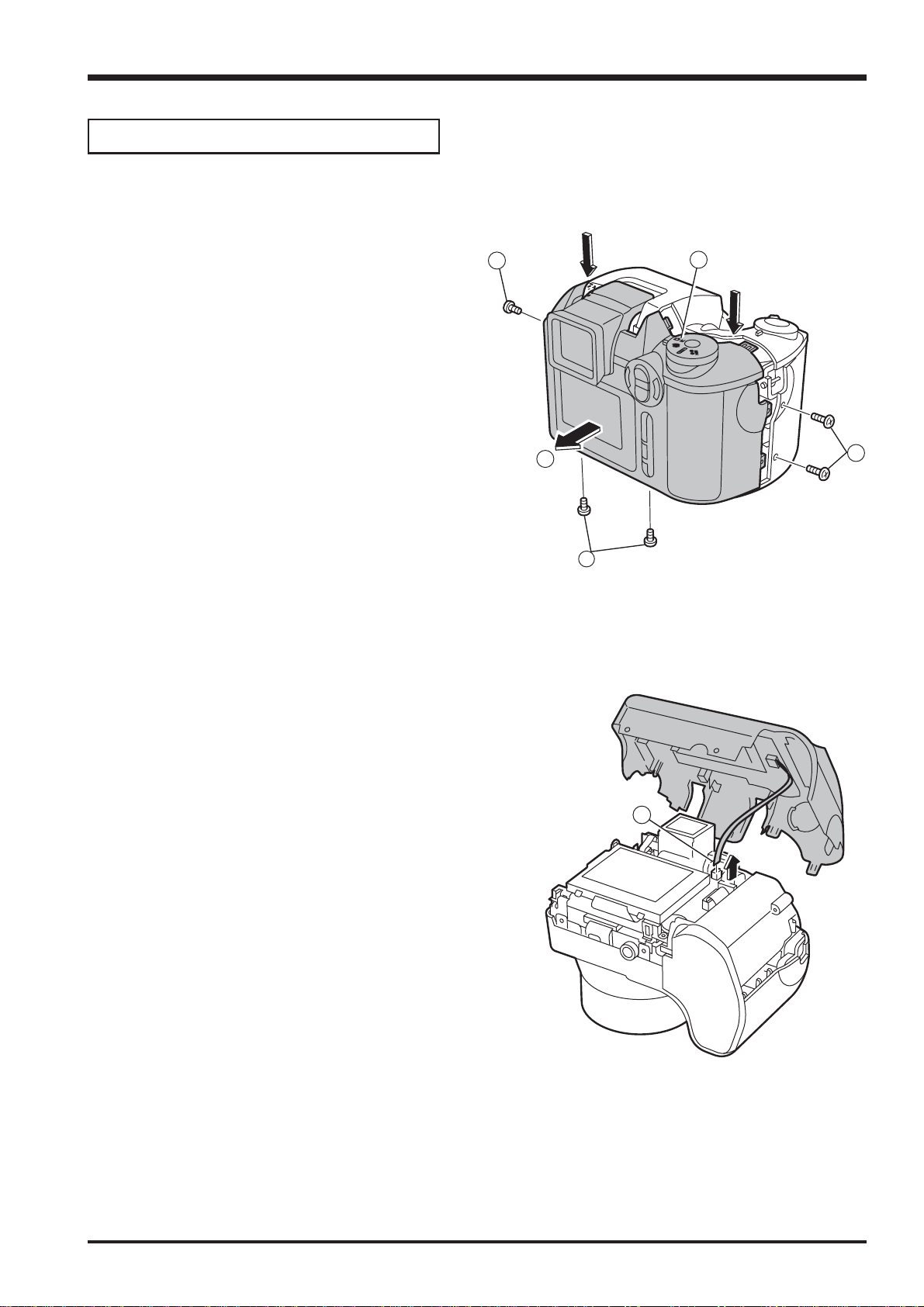
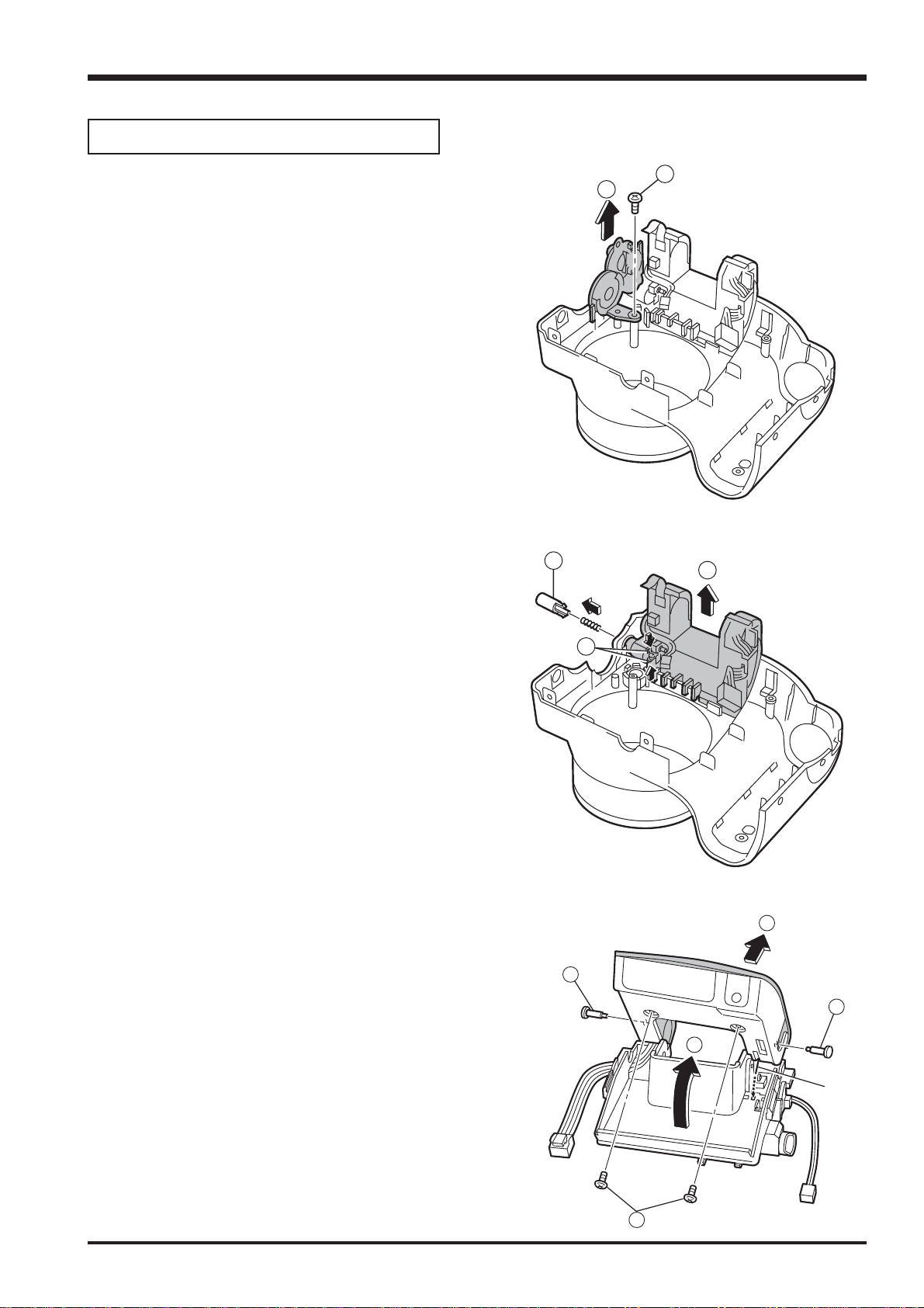
2-2.How to Disassemble the CABI R ASSY
Remove in the order indicated by circled numbers.
2.Disassembly
(1) Change to the Manual camera mode.
(2) Remove three screws.
(3) Remove two special shape screws.(3ULR 1.5X5.0)
* Because the screws are special shape,use the
exclusive use jig driver(ZJ00583-100).
(4) Remove CABI REAR while pressing part A in the
direction of (3).
* Reassemble CABI REAR in the state of the Manual
camera mode.
<Step1>
2
A
1
A
4
2
3
(5) Remove connector (CN203).
<Step2>
4
9
2.Disassembly
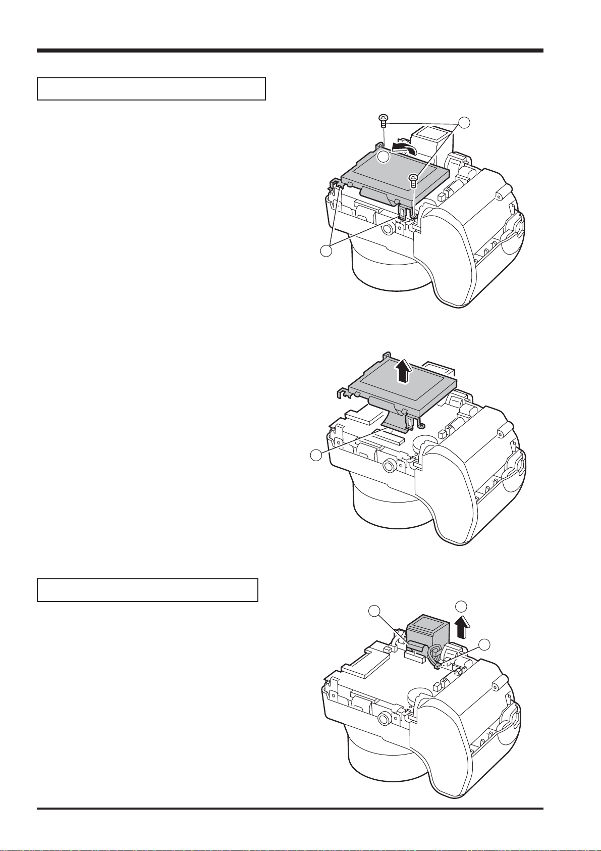
2-3.Removing LCD ASSY / LCD FRAME
Remove in the order indicated by circled numbers.
(1) Remove two screws.
(2) Remove the hook of LCD FRAME (two places), and raise
LCD ASSY in the direction of the arrow.
Fine Pix S3100/S3500 SERVICE MANUAL
<Step1>
1
2
2
(3) Remove the lock of CN401, and remove LCD ASSY/
LCD FRAME to the direction of the arrow.
2-4.Removing EVF CONST
Remove in the order indicated by circled numbers.
(1) Remove CN452.
(2) Remove CN451.
(3) Remove EVF CONST in the direction of the arrow.
<Step2>
3
<Step1>
1
3
2
10
Fine Pix S3100/S3500 SERVICE MANUAL
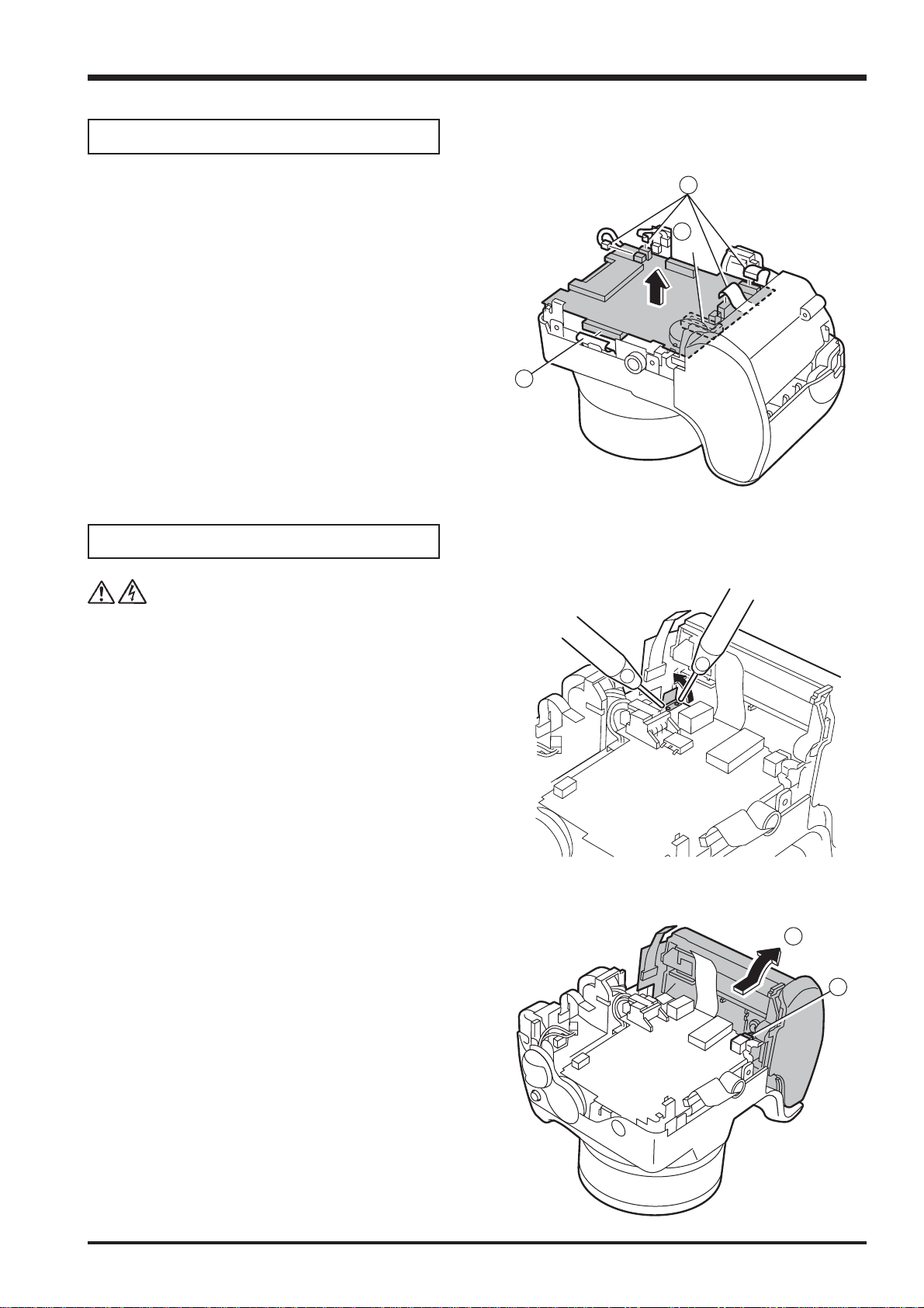
2-5.Removing MAIN PWB ASSY
Remove in the order indicated by circled numbers.
(1) Remove CN201 CN202, CN281, CN301and CN101.
(2) Remove MAIN PWB ASSY in the direction of the arrow
while removing the connector in A part.
2.Disassembly
<Step1>
1
2
A
1
2-6.Removing BATTERY HOLDER ASSY
Remove in the order indicated by circled numbers.
(1) Peel off the UL tape, and do discharge.
(note)
Make the power lever a turning off mode.
(1) Raise BATTERY HOLDER ASSY in the direction of the
arrow.
(2) Remove CN601.
<Step1>
<Step2>
1
1
1
2
* Reassemble BATTERY HOLDER ASSY in the state of
the power lever off.
11
2.Disassembly
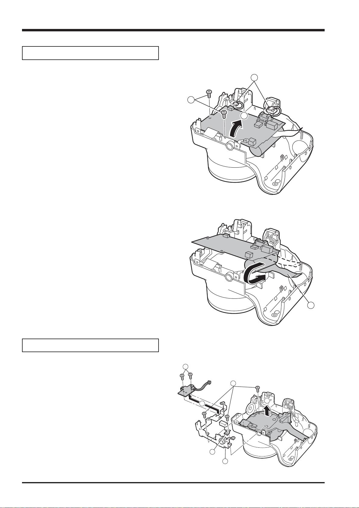
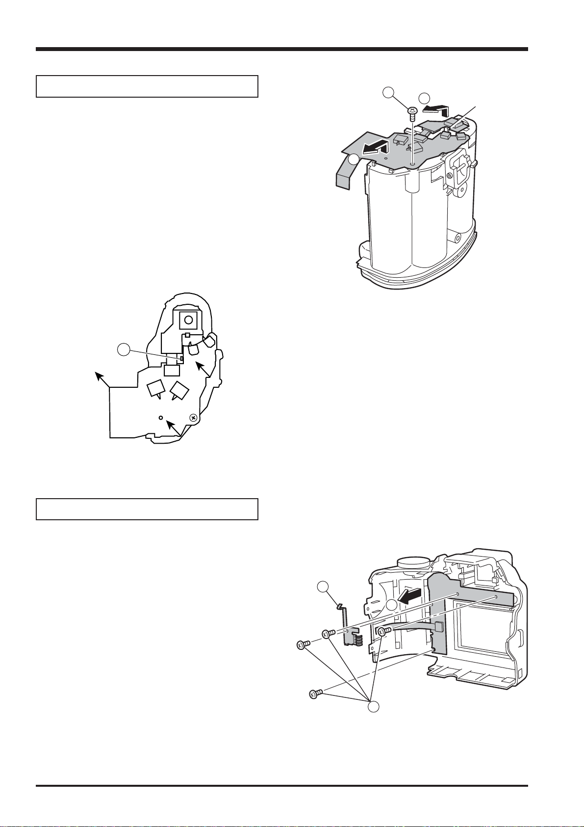
2-7.Removing DCST PWB ASSY
Remove in the order indicated by circled numbers.
(1) Remove two screws.
(2) Remove CN701, CN751.
(3) Raise DCST PWB ASSY in the direction of the arrow.
Fine Pix S3100/S3500 SERVICE MANUAL
<Step1>
2
1
3
(4) Remove FPC of LENS CONST in the direction of the
arrow.
2-8.Removing LENS CONST
Remove in the order indicated by circled numbers.
(1) Remove three screws.
(2) Remove CCD EARTH PLATE, EARTH PLATE.
(3) Remove two screws.
(4) Remove VCON PWB ASSY.
(5) Remove MAIN FRAME.
(6) Remove LENS CONST in the direction of the arrow.
<Step2>
<Step1>
3
4
1
4
6
12
2
5
Fine Pix S3100/S3500 SERVICE MANUAL
4
5
6
2-9.Removing STROBE CONST/ST TOP
2.Disassembly
Remove in the order indicated by circled numbers.
(1) Remove one screw.
(2) Remove STRAP BASE(R) in the direction of the arrow.
(3) Remove one screw.
(4) Remove the hook of ST BUTTON, and pull out ST
BUTTON in the direction of the arrow.
(5) Remove STROBE CONST in the direction of the arrow.
<Step1>
1
2
<Step2>
<Step3>
(6) Pull out two ST SHAFT.
(7) STOROBE must improve in pop-up.
(8) Remove two screws.
(9) Remove ST TOP in the direction of the arrow.
7
8
9
10
7
13
2.Disassembly
Fine Pix S3100/S3500 SERVICE MANUAL
2-10.Removing MSW PWB ASSY and RSW PWB ASSY
Remove in the order indicated by circled numbers.
(1) Remove one screw.
(2) Remove the hook of BATTERY HOLDER, and
remove RSW PWB ASSY and MSW PWB ASSY.
* Tighten the screw while joining MSW PWB ASSY to
(A), and confirm the thing which MSW PWB ASSY and
(A) are fit.
A
RSW PWB
<Step1>
1
2
2
hook
MSW PWB ASSY
2-11.Removing KEY PWB ASSY
Remove in the order indicated by circled numbers.
(1) Remove four screws.
(2) Remove EARTH PLATE.
(3) Remove KEY PWB ASSY in the direction of the arrow.
<Step1>
2
3
14
1

Fine Pix S3100/S3500 SERVICE MANUAL
2-12.Disassembly of LENS CONST
Do not disassemble LENS CONST !
When LENS CONST is disassembled, the assembly accuracy cannot be kept.
2.Disassembly
15
2.Disassembly
2-13.Location of Sheet parts
[Attention when Reassemble.]
Do not use removed “Sheet Parts”.
Use surely new parts at the time of reassembly.
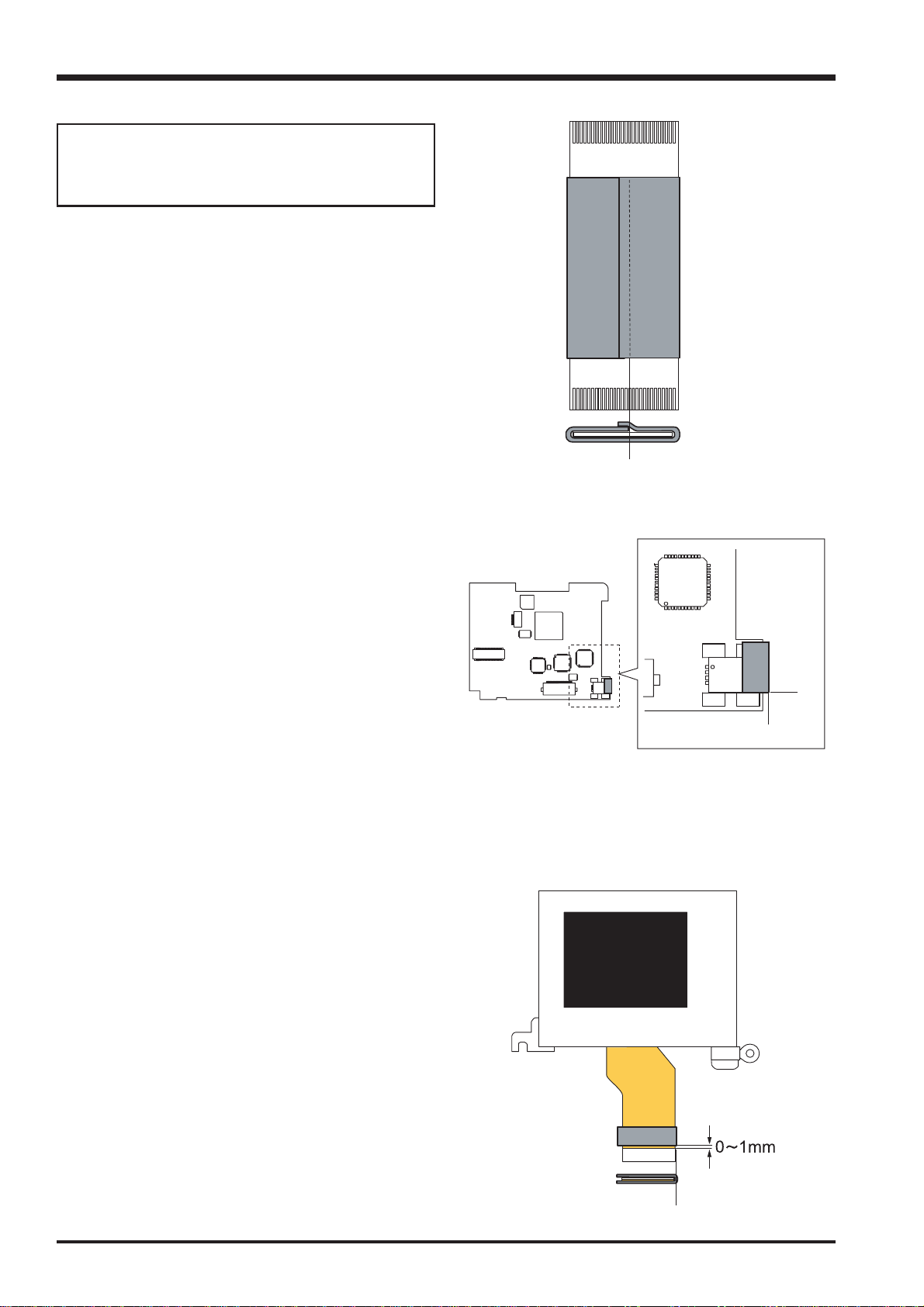
2-13-1.CCD EMI SHEET (FZ06017-100)
Taking the center of the terminal side (A) on the FFC
(CCD-MAIN) as the starting point, stick the sheet to the
FFC so that it encircles the FFC once.
[Note]
The tape must not cover the reinforcing plate on the rear
side of the FFC terminal.
Fine Pix S3100/S3500 SERVICE MANUAL
A
2-13-2.GASKET USB (BB18395-100)
Stick the GASKET USB to the USB connector (CN205)
on the MAIN PWB SIDE-B.
Stick the GASKET USB so that it is aligned with the lower
edge of the USB connector (A) and the edge of the
insertion slot (B).
2-13-3.LCD-EMI SHEET (FZ6000-100)
Stick the LCD-EMI SHEET to the FPC section on the
LCD CONST. Stick the sheet so that it is 0-1 mm from
the edge of the FPC reinforcing plate and folds back to
the rear side at the side of the FPC (A).
MAIN PWB SIDE-B
A
B
16
A
Fine Pix S3100/S3500 SERVICE MANUAL
B
A
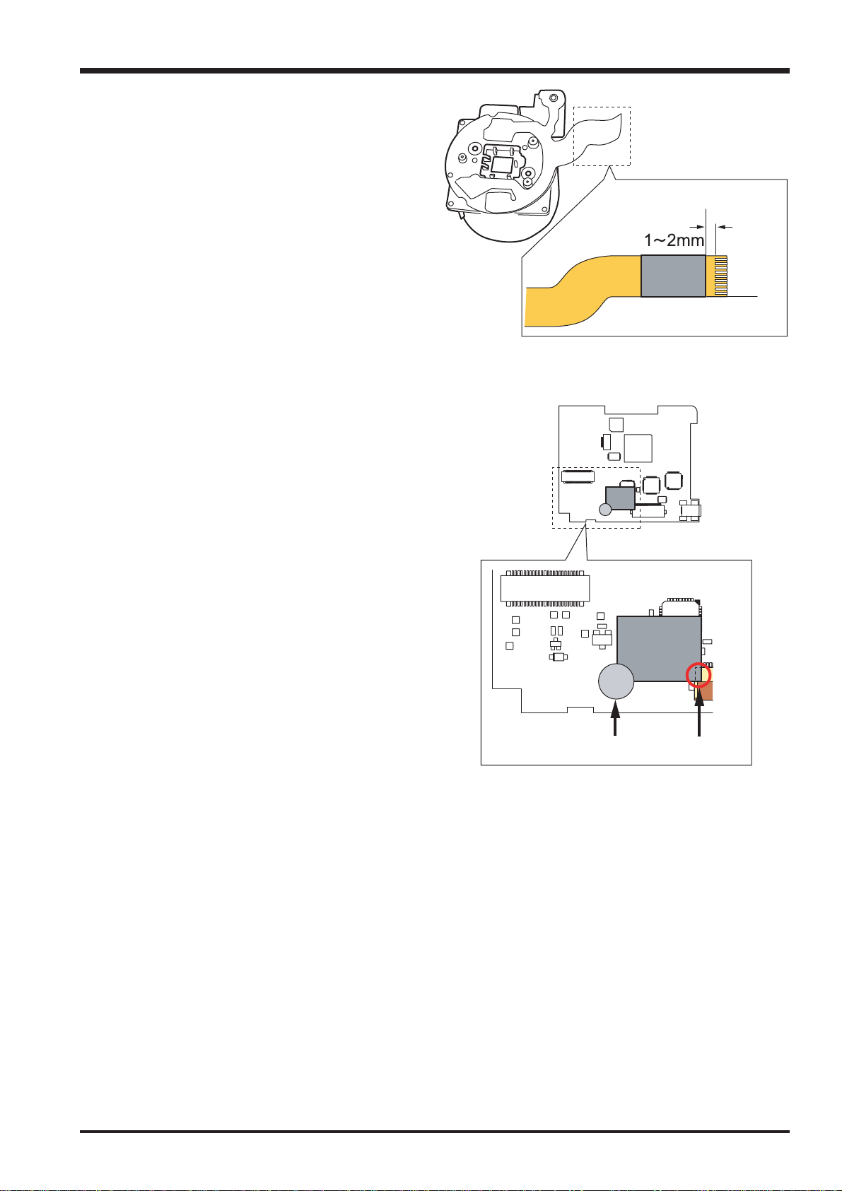
2-13-4.LENS-EMI SHEET (FZ06018-100)
Stick the LENS-EMI SHEET onto the LENS-side FPC on
the LENS CONST. Stick the sheet so that it is aligned
with the edge of the FPC (A) and is 1-2 mm from the
terminal (B).
2-13-5.EMI SHEET AF (FZ05587-100)
(1) Stick the EMI SHEET AF so that it is aligned with the
CN101 indentation (A) on MAIN PWB SIDE-B.
(2) To secure the EMI SHEET AF, apply UL adhesive
(ZS00095-100) so that it covers the corner of the sheet
(B).
2.Disassembly
MAIN PWB SIDE-B
B
A
17

2.Disassembly
MEMO
Fine Pix S3100/S3500 SERVICE MANUAL
18

Fine Pix S3100/S3500 SERVICE MANUAL
3.Schematics
3.Schematics
3-1.Cautions
Precautions in parts replacement
Do not reuse detached electronic components. Use only new components.
The negative side of tantalum capacitors is weak against heat. Handle with care.
With the exception of Chemical capacitor and tantalum capacitors, the voltage of capacitors of a 50V or lower withstand voltage
is not labeled.
Unless specified, electronic component resistance is 1/16W.
K = 1000 , M = 1000 K
3-2.Names and Functions of Basic Blocks
Board Name Block name Function
LENS CONST CCD BLOCK * CCD output
MAIN PWB ASSY CAM BLOCK * Analog to digital conversion of CCD output(IC103)
* CCD driver(IC101/102)
MOTOR BLOCK * Zoom/AF/shutter/iris drive(IC301)
EVF BLOCK * EVF control(IC451)
PROCESS BLOCK* USB communication(IC205)
* System control/SW detection management (IC205)
DCST PWB ASSY DCDC BLOCK * Each power supply generation(IC601)
FlashBLOCK * Flash luminescence processing(IC702)
IPS BLOCK *Power_ON control/FLASH control(IC751)
MSW PWB ASSY MSW BLOCK * Operation SW(power supply/mode)
RSW PWB ASSY RSW BLOCK * Operation SW(shutter)
KEY PWB ASSY KEY BLOCK * Operation SW(EVF<->LCD/display/U<->D/cancellation/L<->R/OK)
VCON PWB ASSY VCON BLOCK * VIDEO(NTSC/PAL) output
19

3.Schematics
3-3.Explanation of Functions of Important Blocks
It is editing it.
Fine Pix S3100/S3500 SERVICE MANUAL
20
Fine Pix S3100/3500 SERVICE MANUAL
]
S
K
T
A
S
T
]
K
S
K
)
)
K
,
,
,
,
,
,
,
,
[
Block Diagram
3.Schematics
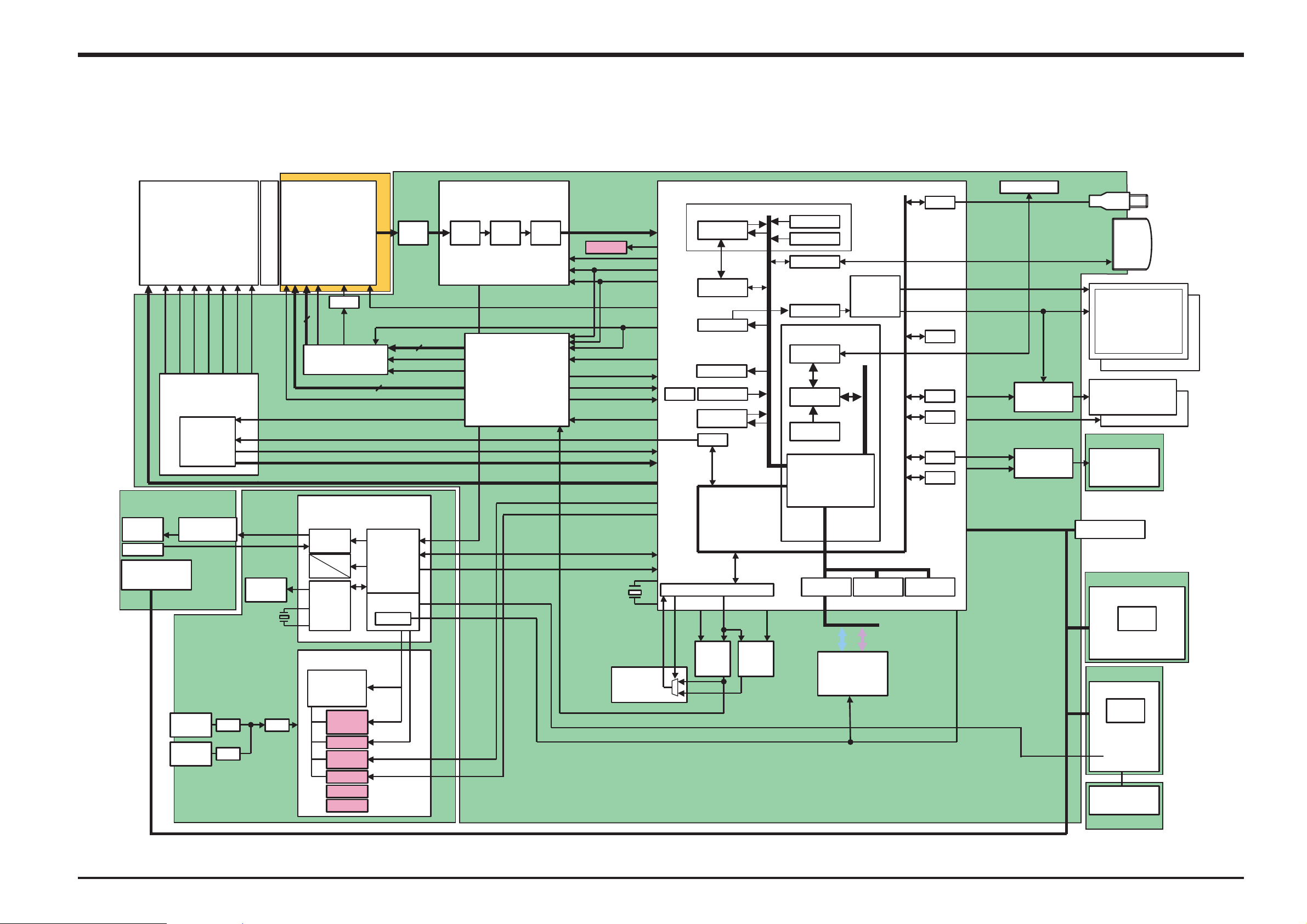
3-4.Block Diagram
6gZOOM LENS
Fujinon
WIDE/TELE
Variable
FM/B
SHUTOUT2
MID IM2+
FM B<FM/A
FM A
SHUTOUT1
MID IM1-
Motor Drv.
M50239HP
STROBE CONST
STRB- XE
P- TR
STROBO_BLK
STROBO SW
STROBO_POPUP
DC IN
5V
BATT
AAg4
DCST PWB
CTL
SML IM2+
SML IM1-
ZPI C
ZM2-
ZPOSI C
ZM1+
IC301
FUSE
FUSE
BA-CCD
ICX488DQF
1/2.7inch
4million pixels
O.LPS
V
V_Drv.
FPI C
MTR CS
IM A,IM B,IM C,FM A,FM B,FM C
BATT
BACKUP
32.768kHz
FUSE
MD2174
V1,V2,V3A,V3B,V4,V5A,V5B,V6
STROBO
DRIVER
Drv.
VHLD
VST
SUB
POWER_ON_IC
CTL
LED
g3
RTC
DC/DC IC
AN30212A_VB
5ch
IC501
AD 5V
MOT_3.3V
CAM 3.3V
D 3.3V
CC D-7.5V
CCD 15V
D_8.5V
D5.6V
STRB UNREG
IC1
IC101
IPS
FF1174
DC/DC
CCD_OUT
H1,H2
IC751
CTL
POWER ON
RESET
PWCTL
PWCTL
3.3V ON
Drv.
g
2
7-0]
SHT PLS(CLS
SHT MNS(CLS
RENESAS AFE
HD49334ANPED
CDS PGA A/D C
SHD,SHP,CPOB
PBLK,ADCLK
V-Pulse
XOFD,XVCL
LM
H
RG
STRB_SY
BAT V
PWR SW
PW SW
EV3
MAIN PWB
3.3V Operation
RTG
FF1170
3.3V Operation
(Programmable)
IC103
IC102
CCD DATA[9-0
CAM 3.3V
CAM SC
OFD CONT
X2 SO,X2 SC
FHP,ZHP,ZPLS
EVF 8.5V ON
48MHz
SELECTOR
CAM ON
AFE C
CAM SO
OCONT
TG C
AVD
AHD
DCL
VRESE
CCD ON
IPS AC
IPS SC
IPS SO
IPS SI
IPS C
A/D
VCLKIN
CLKOUT
IBFC
YCPRO
CGEN
Audio(Serial)
Audio(A/D)
JPEG
SIO
CLKC
OE
27/36
CCD_CLK
RECC
CK48
NT/PAL
IC203IC204
XCS2
3.3V Operation
AUTO
CCDIF
MEDIA
TFDC
ENCD
M32R CPU Core
DEBUG I/F
CPU Core
cache ??k
I-
Peripheral BUS 96MHz
BUS Cont.
SDRAMC
DMAC
Internal
eDRAMA
OE
SEL
I/O Buffer
DATA BUS[0-15] ADDRESS BUS[20- 1]
Flash ROM
2M
M28W320ECT70ZBF2
IC202
IC205
USB
WDT
MFT
ICU
DAC
PORT
Internal
eDRAMB
D+,D-,VBUS
LCD EVR
LCD CS
LCDCLK
LCD HD
LCD VD
LCDDAT[7
EVF RESET
EVF DRV ON
EVF BL ON
VOUT
VIDEO ON
RESET
-
0
JTAG
Driver
EVF-
LC15005 TBMV
VIDEO
DRIVER
IC451
USB
xD
CARD
Slot
(20PIN)
LCD
1.5inch 62MPixel
AU
LED Back Light
EVF(SANYO)
0.33inch 11MPixel
LED Back Light
VCON PWB
VCOM
AV_JACK
Door
SW
-
KSW PWB
Key SW
LED
DRIVER
2
g
LED_Green/LED_Red
Right/Left/Down/Up
OK/BACK/DISP/EVF/LCD
MSW PWB
Mode SW
LED
DRIVER
1
g
LED_Stand-by
MODE1
MODE2
POWER_ON
PLAY/CAM
Release SW
S1/S2
RSW PWB
21
3.Schematics
g
V
W
K
V
V
V
R
_
_
_
_
_
_
R
V
T
W
T
Y
_
V
V
V
V
A
R
W
Y
V
V
T
R
V
V
V
V
V
V
V
V
V
_
_
T
V
V
V
V
V
_
V
K
(
)
V
A
V
g
A
A
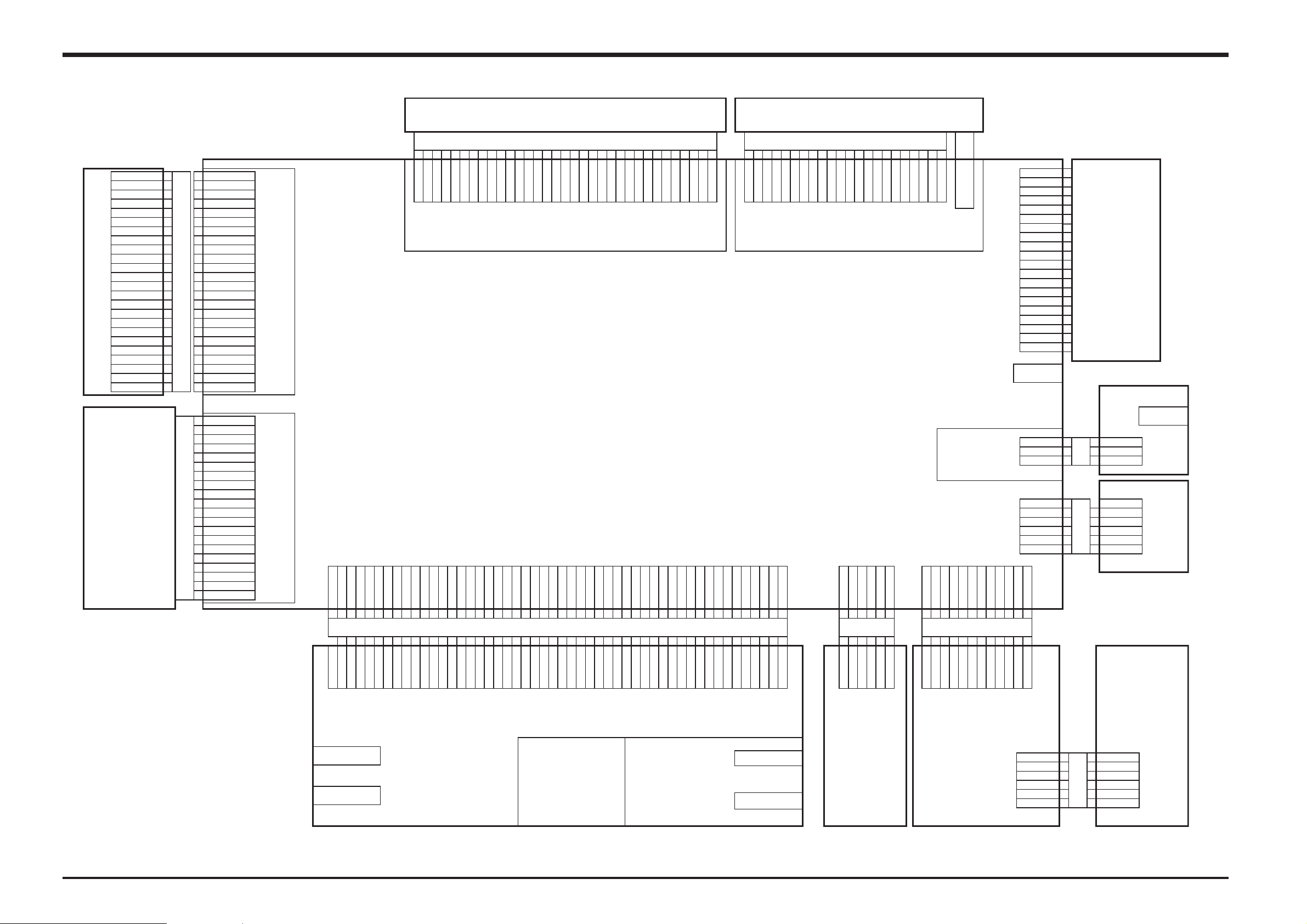
3-5.Overall
Fine Pix S3100/3500 SERVICE MANUAL
FinePix S3100/S3500
Over All
24
23
22
21
20
19
17
16
15
14
13
12
11
10
9
6
3
2
1
1
GND
2
VOUT
GND
3
CCD
4
GND
5
RG
6
H2
7
H1
8
9
GND
CSUB
10
SUB
11
VHLD
12
VST
13
V1
14
V2
15
V3A
16
V3B
17
V4
18
V5A
19
V5B
20
21
V6
22
VL
GND
23
GND
24
ZPI_C1
ZPI
2
3
3V
4
SHUTOUT1
5
SHUTOUT2
6
MID IM1-
7
MID IM2+
8
SML IM1-
9
SML IM2+
10
FM/A
11
FM/B
12
FM A
13
FM B
MOTOR_FPC
14
FPI
15
FPI
16
3V
17
ZPOSI
18
ZPOSI
19
ZM1+
20
ZM2-
+15V
E
C
E
CAM BLK
20FLT_SM1
MOTOR BLK
C
E
GND
CCD_+15
GND
RG
H2
GND
CSUB
SUB
VHLD
CCD_PWB
FH12_24S_0.5SH
VST
V1
V2
V3
V3B
V4
V5
V5
V6
VL
GND
GND
B
LENZ UNIT
D_3.3V 2 GND 3 D_3.3V 4 GND 5 D_3.3V 6CAM_3.3V 7D_3.3V 8 CAM_3.3V
1
6
2 8 3 7 4
GND
D_3.3
5
GND
D_3.3
D_3.3
CAM_3.3
1
LCD UNIT
LCD_FPC
1 22
4
5 26 37 48 510 69
f_L
f_H
VC2
VC1
VGH
VCOM
CCD_15V 9 MOT_3.3V 11MOT_3.3V
10
12
12 ?13 ?14 ?15 ?16 ?17
11
9 ?10
8 ?7
D_3.3
CCD_15
MOT_3.3
CAM_3.3VMOT_3.3
of
of
V
V
CCD_15V
D_8.5V
GND
D_8.5V
13
CCD_15
GND
14
15
16
GND
GND
D_8.5
D_8.5
17
VC4
D_5.6V
18
18 ?20 ?19
D_5.6
AVD D1
CCD
19
CCD
11 112 213314415516617
FRP
C
VCC
LED_
LED_
FB
F12_33S 5SH
H
LCD BLK
9831S_50Y930
CCD
D_5.6V
D_5.6V 22AD_5V 23N.C. 24AD_5V 25GND 26EVF8.5VON 27GND 30LED_ST 29VREF 31IPS_CS 32LED_G 33IPS_SI
20
21
B to B C
21
22
23
25
24
N.C.
AD_5
AD_5
D_5.6
D_5.6
CCD
25
23
DD4
DD3
DD2
26
DD1
DD0
AGND
18S220S119
AVD D
VSYNC
HSYNC
21
DCL
0.
MAIN PWB
PROCESS BLK
R
LED_
IPS_SO 36GND 37IPS_SCK 38GND 40IPS_ACT 39PW_SW 41BAT_V 42PWR_SW 43EV3 44X2_3.3V 45RESET 46N.C. 47STRB_SY 48GND 50GND
34 35
33
32
IPS_CS
36 138 240
34 35 49
IPS_SI
LED_
LED_G
IPS_SO
26
GND
28
N
27
284 305 29H131
GND
EVF8.5VON
CCD_ON
CCD_ON
VREF
LED_S
27 28
SEL0
37
GND
EVF UNIT
29
30D031
GB
32D233
ISCI
VCC
ISD
12345678 109 11 12 13 14 15 16 17 18 20 19 21 22
ST
ENB
GND
COM
CKV1
CKV2
CS
DSD
DSG
XDSG
B
22FLT_SM1
EVF BLK
VDD
CKH2
CKH1
VSS
STH_EVF
XSTH_
CSH
EVF
SM02B_SRSS_TB
GND 1
2
CARD
R/B
EVF_BL
PES018_20C31106
RE
CE
CLE
ALE
WE
WP
GND
D1
D3
D4
D5
D6
D7
VCC
VCC
3
4
5
6
7
8
9
10
11
12
13
14
15
16
17
18
19
20
xD_CARD_CN
USB_CN
59110_0428
VCON
AV_J ACK
HSJ1650_010025
3
POP_FFC
VBS
2
1
?
?
?
???
POP_SW
VBS 1
2
VIDEO BLK
GND
DET
3
SM03B_SRSS_TB
GND
1
2
3
4
5
6
SPEAKER+
SPEAKER+
STRB_POP
SPEAKERSPEAKER-
8
8 41 10 42 9 43
GND
9
GND
MODE2
MODE2
10
06FLT_SM1
MODE1
11
11 3 12
MODE1
LED_ST
5V
12
5
LED_S
06FLT_SM1
RLDU 4LED_G
GND
LED_R
OK/B/D/E_L
N.C.
49
A3.3V
3
1
5 6
KSW_FFC
45
44
46
47
50
EV3
X2_3.3
N.C.
RESE
GND
GND
STRB_S
GND
BAT_
PW_S
IPS_AC
IPS_SC
PWR_S
A3.3
3
KEY2
KEY1
4
5
6
GND
LED_
LED_G
12FLT_SM1
PW_SW 2 EV3 3 GND 4 PLAY 5 A3.3V 6 S2
MSW_FFC
2
4 CS5 6
EV3
GND
PLA
PW_S
A3.3
S1
7
S2
S1
6FLZ_SM1_TB
DCST PWB
DC CN
HEC3654_012010
POWER ON BLK
STRB BLK
BATT
CGP4702_0101
22
PhTr_CN
53261_0290
Xeon_CN
S04B_PASK_2
KSW
PWB
MSW
6FHJ_SM1_TB
GND
GND
GND
GND
1
RSW_FFC
GND
GND
S2
GND
Fine Pix S3100/S3500 SERVICE MANUAL
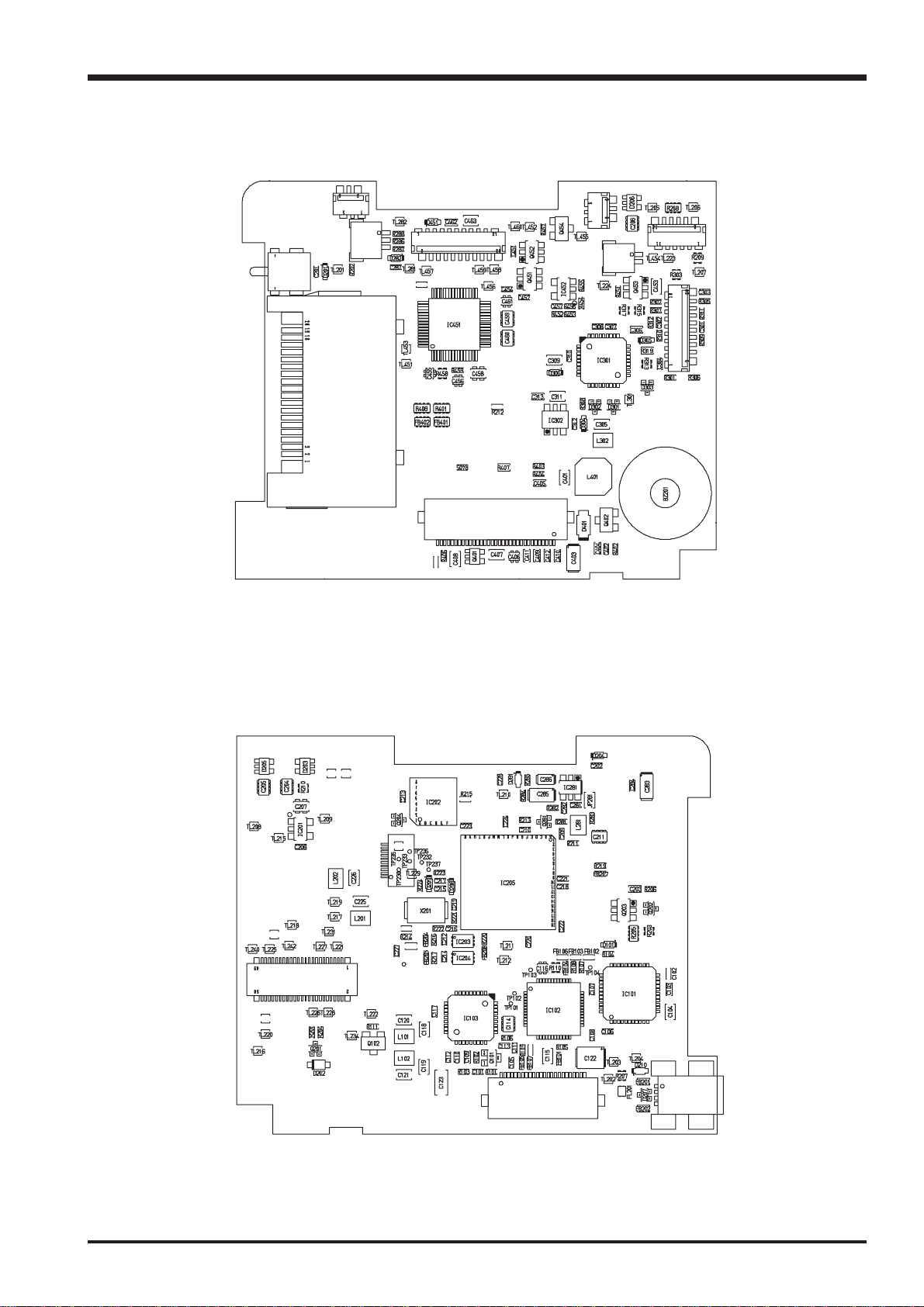
3-6.Mounted Parts Diagrams
3-6-1.MAIN PWB ASSY Component Location
CN201
CN281
SW201
CN204
CN452
3.Schematics
CN203
CN202
CN451
CN301
SIDE-A
CN206
CN401
CN207
SIDE-B
CN101
CN205
23
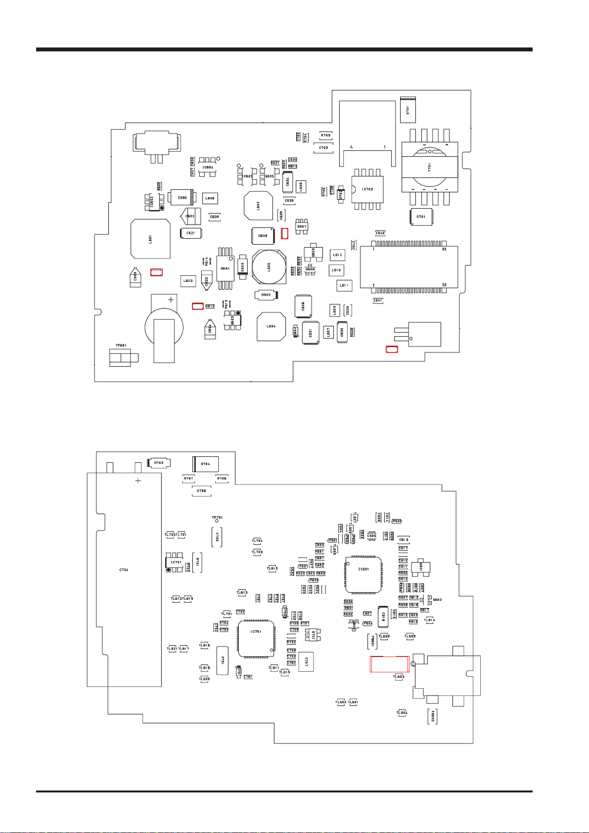
3.Schematics
3-6-2.DCDC PWB ASSY Component Location
CN751
F603
F604
BT751
Fine Pix S3100/S3500 SERVICE MANUAL
CN701
F605
CN602
CN601
SIDE_A
F602
24
F501
J601
SIDE_B
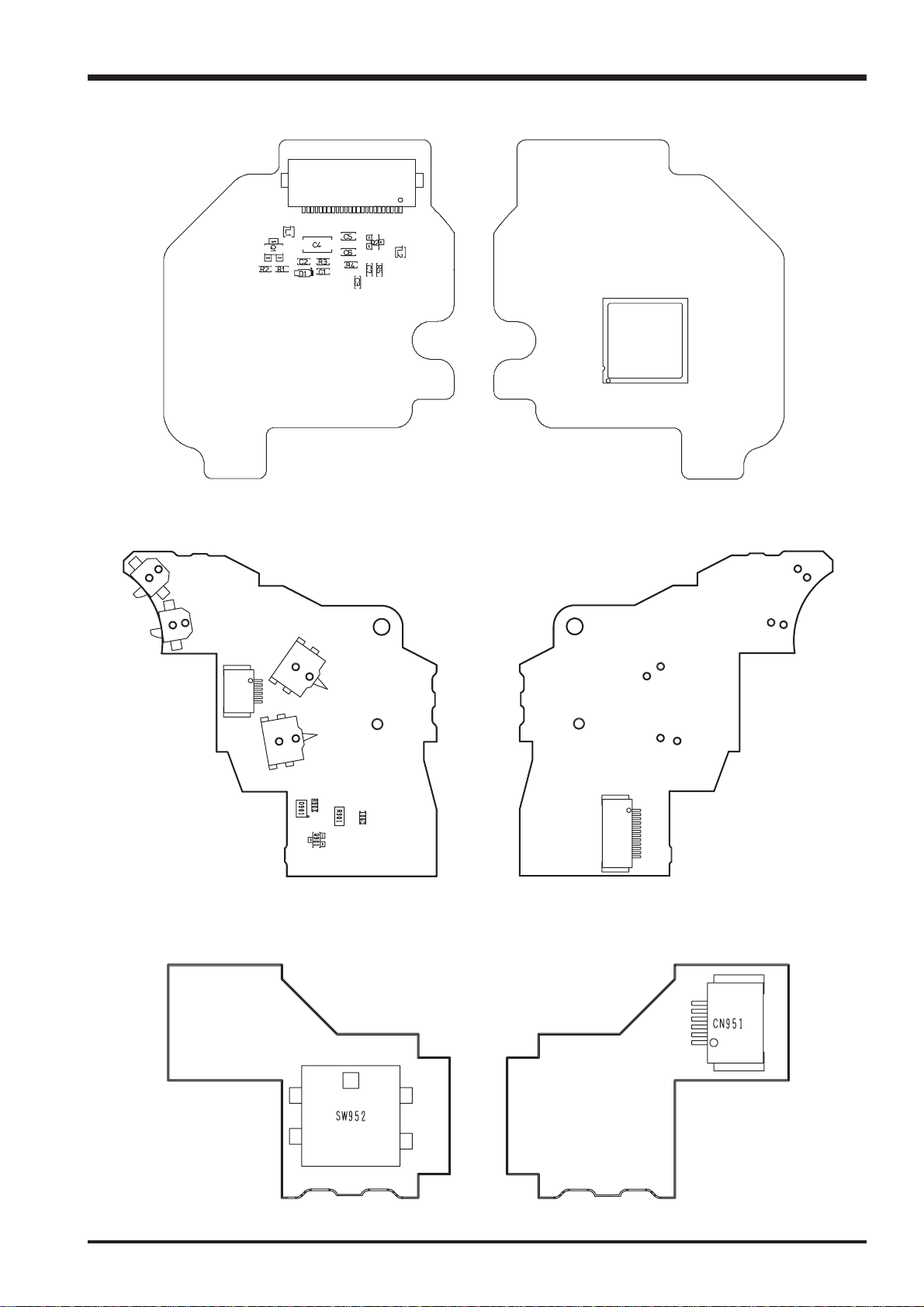
Fine Pix S3100/S3500 SERVICE MANUAL
3-6-3.CCD PWB CONST Component Location
CN1
3.Schematics
IC1
SIDE_A
3-6-4.MSW PWB UNIT Component Location
SW903
SW904
SW902
CN902
SW901
SIDE-ASIDE-A
SIDE_B
CN901
SIDE-B
3-6-5.RSW PWB UNIT Component Location
SIDE-A
SIDE-B
25
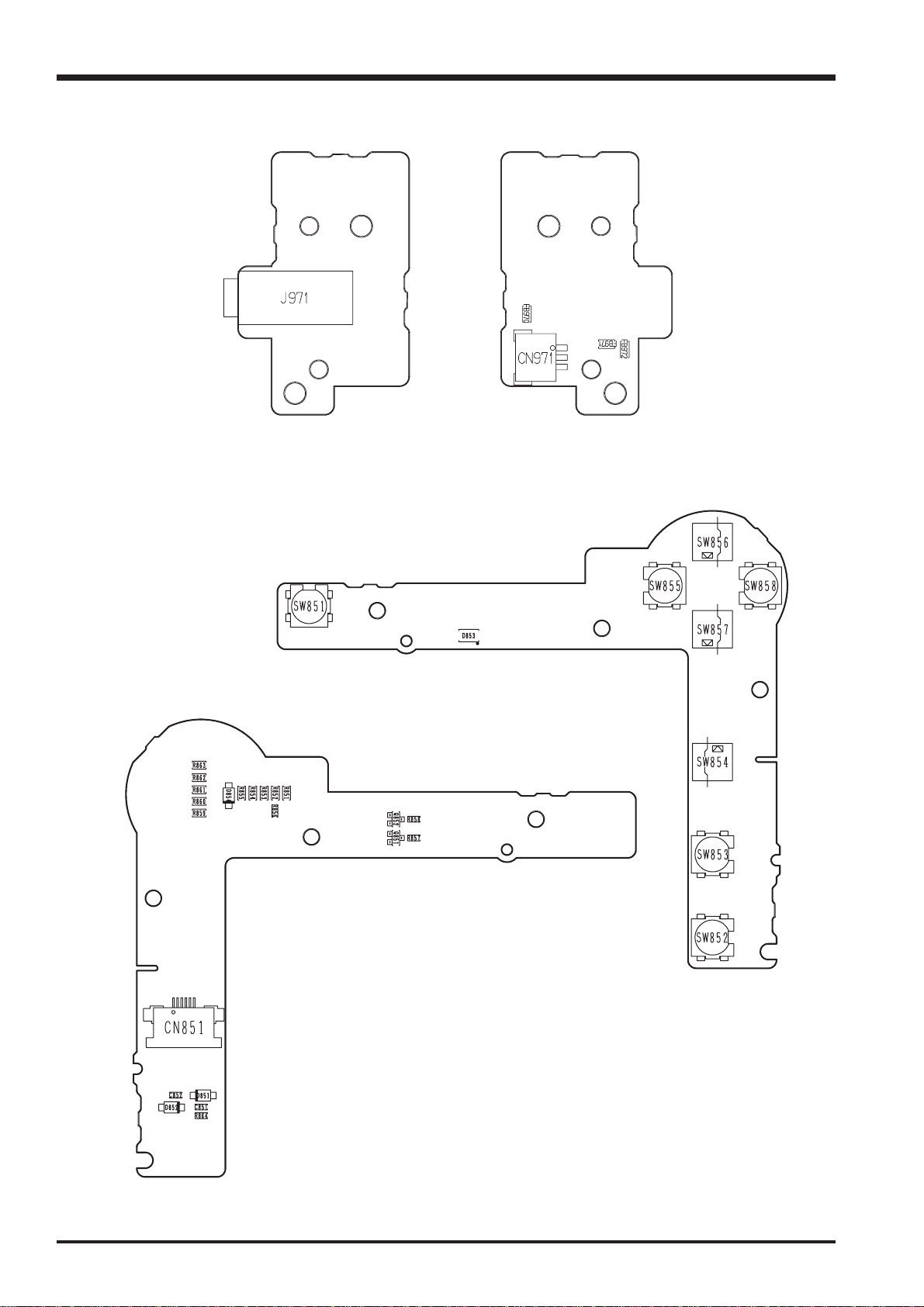
3.Schematics
3-6-6.VCON PWB UNIT Component Location
Fine Pix S3100/S3500 SERVICE MANUAL
SIDE-A
3-6-7.KEY PWB UNIT Component Location
SIDE-B
SIDE-A
26
SIDE-B
 Loading...