

FUJIFILM FinePix S3000 Service Manual
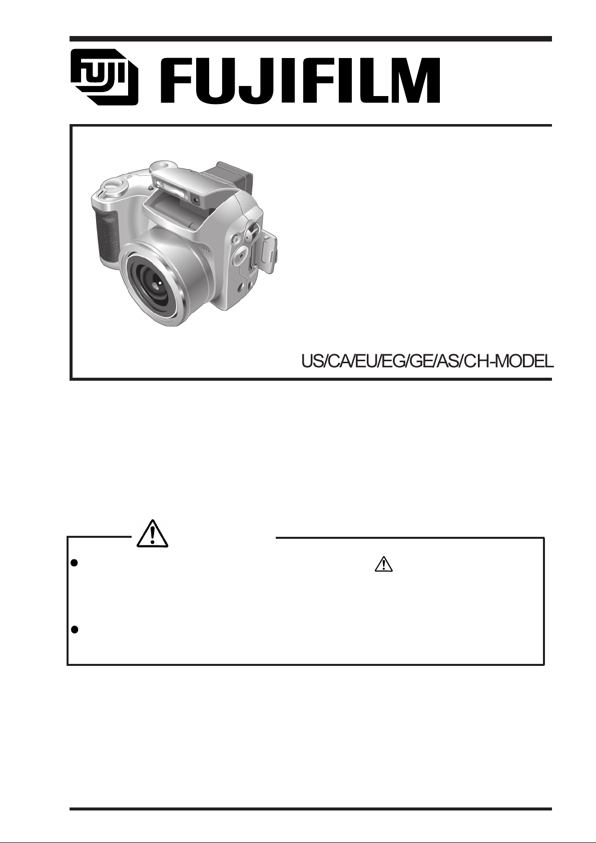
DIGITAL CAMERA
FinePix S3000
SERVICE MANUAL
WARNING
THE COMPONENTS IDENTIFIED BY THE MARK “ ” ON THE SCHEMATIC
DIAGRAM AND IN THE PARTS LIST ARE CRITICAL FOR SAFETY.
PLEASE REPLACE ONLY BY THE COMPONENTS SPECIFIED ON THE SCHE-
MATIC
DIAGRAM AND IN THE PARTS LIST.
IF YOU USE PARTS NOT SPECIFIED, IT MAY RESULT IN A FIRE AND AN
ELECTORICAL SHOCK.
Ref.No.:ZM518-104
FUJI PHOTO FILM CO.,LTD.
Printed in Japan 2004.08

SAFETY CHECK-OUT
2. Check the interboard wiring to ensure that no wires
are “pinched” or contact high-wattage resistors.
FinePix S3000 Service Manual
2.5A 125V
2.5A 125V
RISK OF FIREREPLACE FUSE
AS MARKED
WARNING!
HIGH VOLTAGE
2

TABLE OF CONTENTS
1.General .......................................... 5
1-1. Product specification .......................................... 5
1-2. Explanation of Terms.......................................... 7
1-3.Names of External Components.......................... 7
2. Disassembly.................................. 9
2-1.Names of Internal Parts.................................... 9
2-2.How to Disassemble the CABI R ASSY. ........... 9
2-3.Removing LCD ASSY / LCD FRAME. .............11
2-4.Removing EVF CONST. ..................................11
2-5.Removing MAIN PWB ASSY. ..........................11
2-6.Removing BATTERY HOLDER ASSY..............11
2-7.Removing DCST PWB ASSY.......................... 13
2-8.Removing LENS CONST................................ 13
2-9.Removing STROBE CONST/ST TOP. ............ 13
2-10.Removing MSW PWB ASSY and RSW PWB ASSY . ... 15
2-11.Removing KEY PWB ASSY........................... 15
2-12.Removing CCD PWB CONST...................... 15
2-13.Location of Sheet parts................................. 17
2-13-1.FFC (CCD-MAIN)..........................................................17
3. Circuit Diagrams.......................... 17
3-1.Cautions ......................................................... 17
3.2 Names and Functions of Basic Blocks............ 17
3-3.Explanation of Functions of Important Blocks. 19
3-3-1.Technical Overview ........................................................19
3-3-2.Explanation of Functions of Individual Blocks................19
3-4.Block Diagram ................................................ 19
3-5.Overall ............................................................ 21
3-6.Mounted Parts Diagrams................................ 21
3-6-1.MAIN PWB ASSY Component Location ........................21
3-6-2.DCDC PWB ASSY Component Location.......................23
3-6-3.CCD PWB CONST Component Location ......................23
3-6-4.MSW PWB UNIT Component Location .........................23
3-6-5.RSW PWB UNIT Component Location..........................23
3-6-6.VCON PWB UNIT Component Location ........................25
3-6-7.KEY PWB UNIT Component Location ...........................25
3-7.Circuit Diagrams............................................. 25
3-7-1.DCDC Block Circuit ........................................................25
3-7-2.PROCESS Block Circuit .................................................27
3-7-3.CAM Block Circuit...........................................................27
3-7-4.EVF Block Circuit............................................................29
3-7-5.STROB Block Circuit ......................................................29
3-7-6.LCD Block Circuit ...........................................................31
3-7-7.MOTOR Block Circuit .....................................................31
3-7-8.KEY-IO Block Circuit.......................................................33
3-7-9.KEY-IC Block Circuit .......................................................33
3-7-10.CCD Block Circuit .........................................................35
3-7-11.MSW Block Circuit........................................................35
3-7-12.KSW Block Circuit ........................................................35
3-7-13.RSW Block Circuit ........................................................35
3-7-14.VCON Block Circuit ......................................................35
4.Adjustment ...................................37
4-1.Important point Adjustment when Replacing Major Parts .....37
4-2.The order of adjustment when Major Parts are replaced .....37
4-3.Measuring Instruments Used .................................37
4-4.Use Jig list ...................................................... 37
4-4.Jig Connections.............................................. 37
4-5.Environmental Setup ...................................... 37
4-6.Installing the Jig Drivers on the PC................. 39
4-7.Installing and Starting the Adjustment Sof tware..... 39
4.8 Initial Settings of the Adjustment Software ...... 41
4-9. St arting the Adjustment Software................... 43
4-10. [F4] : CCD Defect Data Input....................... 45
4-11. [F5] CAM Adjustment................................... 49
4-12. [F6] AF Adjustment...................................... 51
4-13. [F1] Battery Volt age Adjustment................... 53
4-14. [F3] LCD Adjustment ................................... 55
4-15. [F7] Flash Adjustment.................................. 57
4-16. [F11] : Video Adjustment.............................. 57
4-17. [F12] : End Setting ....................................... 59
4-18. [F8] Firmware Download.............................. 63
5.Inspection..................................... 67
5-1.Required Measuring Equipment ..................... 67
5-2.Connection of Measuring Equipment.............. 67
5-3.Inspection and Factory Setting ....................... 67
5-4.Factory setting ................................................ 69
6.Parts list ....................................... 69
6-1.Packing and Accessoris ................................. 69
6-1-1.US model ........................................................................69
6-1-2.CA model ........................................................................71
6-1-3.EU model ........................................................................71
6-1-4.EG model ........................................................................73
6-1-5.GE model ........................................................................73
6-1-6.AS model ........................................................................74
6-1-7.CH model ........................................................................75
6-2.Cabinet F block .............................................. 76
6-2-1.US/CA/EU/EG/GE/AS-MODEL .......................................76
6-2-2.CH-MODEL ......................................................................77
6-3.Inner block...................................................... 79
6-4.Cabinet R block .............................................. 79
6-5.Electrical parts................................................ 81
7.Appendix ...................................... 81
7-1. Version display function................................. 81
7-2.List of Related Technical Updates Issued....... 81
3
FinePix S3000 Service Manual
1.General
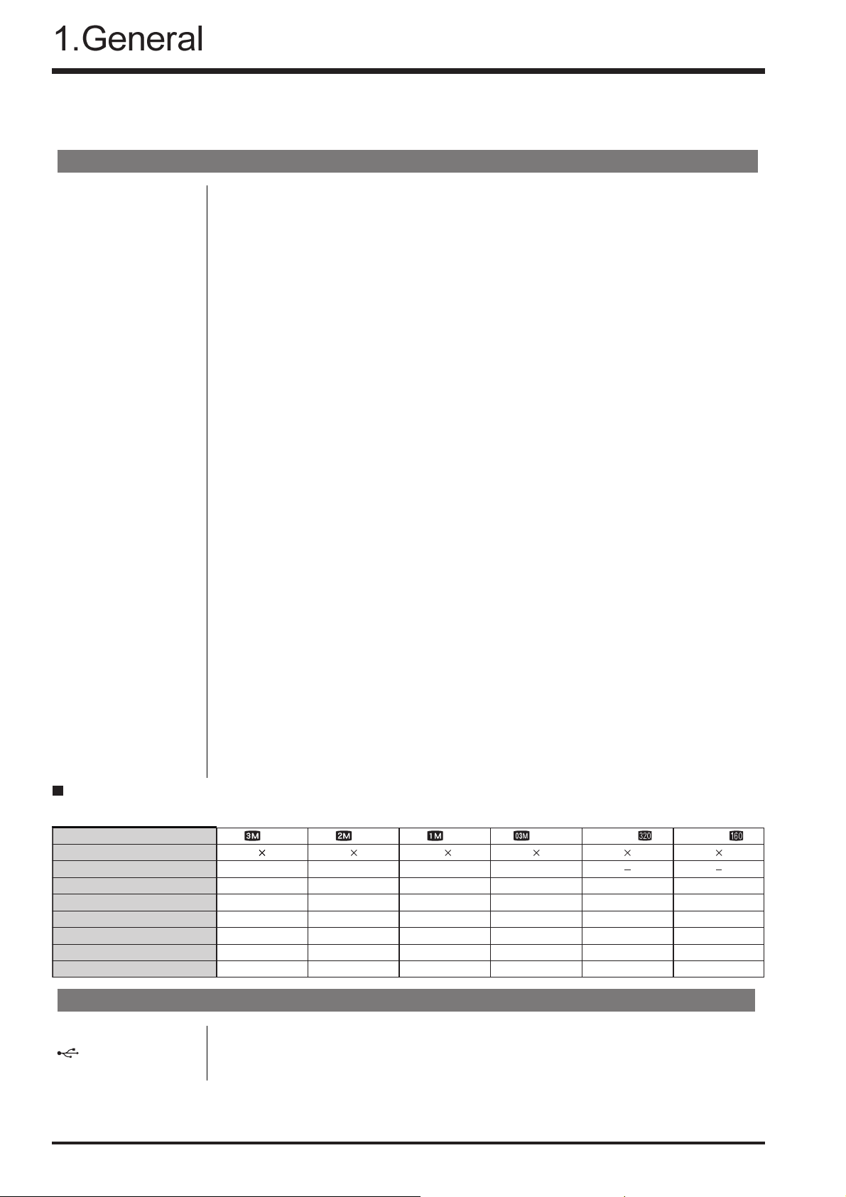
1-1. Product specification
System
Model Digital Camera FinePix S3000
Effective pixels 3.2 million pixels
CCD 1/2.7-inch square pixel CCD with RGB Filter
Number of total pixels: 3.34 million pixels
Storage media xD-Picture Card (16/32/64/128/256/512 MB)
File format Still image: JPEG (Exif Ver.2.2), DPOF-compatible
Movie: AVI format, Motion JPEG
*Design rule for Camera File system compliant
Number of recorded pixels
Lens Fujinon 6 × optical zoom lens F2.8-F3
Focus length f=6 mm-36 mm (equivalent to 38 mm-228 mm on a 35 mm camera)
Focal range Normal: Approx. 80 cm/2.6 ft. to infinity
Shutter speed Auto/SP:1/4 sec. to 1/1500 sec. SP (Night scene mode only):3 sec.
Aperture F2.8/F4.8/F8.2 (Wide-angle) F3/F5.2/F8.7 (Telephoto) automatically selected
Sensitivity At flash off:Equivalent to ISO 100
Exposure control 64 zones TTL metering, Program AE
White balance Auto (7 positions selectable in Manual mode)
Viewfinder 0.33 inches 110,000 pixels electronic viewfinder
LCD monitor 1.8-inches, 62,000 pixels amorphous silicon TFT
Flash (Auto flash using
flash control sensor)
Self-Timer Approx 10 sec. timer clock
Video output NTSC/PAL selectable
Standard number of available frames/recording time per xD-Picture Card
The number of available frames, recording time or file size varies slightly depending on the subjects photographed. Note also that the divergence
between standard number of available frames and the actual number of available frames is greater for xD-Picture Cards with higher capacities.
Quality mode
Number of recorded pixels
Image Data Size
DPC-16 (16 MB)
EPS_FILTER_BUG
DPC-32 (32 MB)
DPC-64 (64 MB)
DPC-128 (128 MB)
DPC-256 (256 MB)
DPC-512 (512 MB)
2048 × 1536 pixels/1600 × 1200 pixels/1280 × 960 pixels/ 640 × 480 pixels
Macro: Approx. 10 cm-80 cm/3.9 in.-2.6 ft.
to 1/250 sec.Manual (A.priority):1/2 sec. to 1/1500 sec.
At flash on:Equivalent to ISO 100-200 (automatically selected)
(exposure compensation available in Manual mode)
Effective range: Wide Approx. 0.3 m-3.5 m (1.0 ft.-11.5 ft.)
Tele Approx. 0.8 m-3.5 m (2.6 ft.-11.5 ft.)
Flash modes: Auto, Red-Eye Reduction, Forced Flash, Suppressed Flash, Slow
Synchro, Red-Eye Reduction + Slow Synchro
(when the pop-up flash is stowed: Suppressed Flash)
3M
2048 1536
780 KB
19
40
81
162
325
651 818 1101 3993
2M
1600 1200
630 KB
25
50
101
204
409
1M
1280 960
470 KB
33
68
137
275
550
0.3M
640 480
130 KB
122
247
497
997
1997
Movie
320 240
Approx. 98 sec.
Approx. 199 sec.
Approx. 6.6 min.
Approx. 13.3 min.
Approx. 26.7 min.
Approx. 53.5 min. Approx. 182.5 min.
Movie
160 120
Approx. 5.6 min.
Approx. 11.3 min.
Approx. 22.7 min.
Approx. 45.5 min.
Approx. 91.2 min.
Input/Output Terminals
Video output socket 2.5mm dia. jack
(USB) socket For file transfer to a computer
DC Input Socket for specified AC Power adapter AC-5VH/AC-5VHS (sold separately)
4

Power Supply and Others
Power supply Use one of the following:
• 4AA-size alkaline batteries
• 4AA-size Ni-MH (Nickel-Metal Hydride) batteries (sold separately)
• AC Power Adapter AC-5VH/AC-5VHS (sold separately)
Guide to the number
of available frames
for battery operation
EPS_FILTER_BUG
Battery type
Alkaline batteries
Using LCD monitor
Approx. 350 frames
Using EVF
*
Approx. 400 frames
*
Ni-MH batteries
2100 mAh
This indicates the number of available frames shot consecutively at room temperature with a flash use rate of 50%. Note that these figures may vary depending
on the ambient temperature and the amount of charge in the battery. The number
of available shots or available shooting time will be lower in cold conditions.
Conditions for use
Camera dimensions 99.7 mm × 77.3 mm × 69.3 mm/3.9 in. × 3.0 in. × 2.7 in.
(W/H/D) (not including accessories and attachments)
Camera mass (weight)
Weight for photography
Accessories 16MB, xD-Picture Card (1) Supplied with: Anti-static case (1)
Optional Accessories xD-Picture Card
Temperature: 0oC to +40oC (+32oF to +104oF); 80% humidity or less (no condensation)
Approx. 283 g/10.0 oz.
(not including accessories, batteries or xD-Picture Card)
Approx. 411 g/14.5 oz.
(including batteries, xD-Picture Card, lens cap and strap)
LR6 AA-size alkaline batteries (4) Adapter Ring (1)
Lens Cap (1) Strap (1)
Video cable (1) (plug (2.5 mm dia.) to pin-plug) Approx. 1.5 m
USB Interface Set (1)
• CD-ROM: Software for FinePix SX (1)
• USB cable with Noise Suppression core (1)
• Quick start guide for Camera and Software installation (1)
Owner’s Manual (1)
DPC-16 (16 MB)/DPC-32 (32 MB)/DPC-64 (64 MB)/DPC-128 (128 MB)/
DPC-256 (256 MB)/DPC-512 (512 MB)
AC Power Adapter AC-5VH/AC-5VHS
Fujifilm Rechargeable Battery 2HR-3UF
Fujifilm Battery charger with Battery BK-NH/BK-NH2
(With Euro type or UK type plug) SC-FX304
Image Memory Card Reader DPC-R1
• Compatible with Windows 98/98 SE, Windows Me, Windows 2000 Profes sional, Windows XP or iMac, Mac OS 8.6 to 9.2.2, Mac OS X (10.1.2 to
10.2.2) and models that support USB as standard.
• Compatible with xD-Picture Card of 16 MB to 512 MB, and SmartMedia of
3.3V, 4 MB to 128 MB.
PC Card Adapter DPC-AD
• Compatible with xD-Picture Card of 16 MB to 512 MB, and SmartMedia of
3.3V, 2 MB to 128 MB.
CompactFlash Card Adapter DPC-CF
• Windows 95/98/98 SE/Me/2000 Professional/XP
• Mac OS 8.6 to 9.2/X (10.1.2 to 10.1.5)
Approx. 400 frames
*
Approx. 450 frames
*With fully charged battery
*
5

FinePix S3000 Service Manual
1-2. Explanation of Terms
DPOF: Digital Print Order Format
DPOF is a format used for recording information on a storage media (image
memory card, etc.) that allows you to specify which of the frames shot using a
digital camera are printed and how many prints are made of each image.
EV: A number that denotes exposure. The EV is determined by the brightness of the
subject and sensitivity (speed) of the film or CCD. The number is larger for bright
subjects and smaller for dark subjects. As the brightness of the subject changes,
a digital camera maintains the amount of light hitting the CCD at a constant level
by adjusting the aperture and shutter speed.
When the amount of light striking the CCD doubles, the EV increases by 1. Likewise, when the light is halved, the EV decreases by 1.
Frame rate (fps): The frame rate is a unit used to indicate the number of images (frames) played
back per second. This camera shoots movie files at 10 consecutive frames per
second, a rate that is expressed as 10 fps. By comparison, TV images are played
at 30 fps.
JPEG: Joint Photographics Experts Group
A file format used for compressing and saving color images. The compression
ratio can be selected, but the higher the compression ratio, the poorer the quality
of the expanded image.
Motion JPEG: A type of AVI (Audio Video Interleave) file format that handles images and sound
as a single file. Images in the file are recorded in JPEG format. Motion JPEG can
be played back by QuickTime 3.0 or later.
PC Card: A generic term for cards that meet the PC Card Standard.
PC Card Standard: A standard for PC cards determined by the PCMCIA.
PCMCIA: Personal Computer Memory Card International Association (US).
White Balance: Whatever the kind of the light, the human eye adapts to it so that a white object
still looks white. On the other hand, devices such as digital cameras see a white
subject as white by first adjusting the color balance to suit the color of the ambient
light around the subject. This adjustment is called matching the white balance. A
function that automatically matches the white balance is called an Automatic
White Balance function.
Exif Print: Exif Print Format is a newly revised digital camera file format that contains a vari-
ety of shooting information for optimal printing.
6
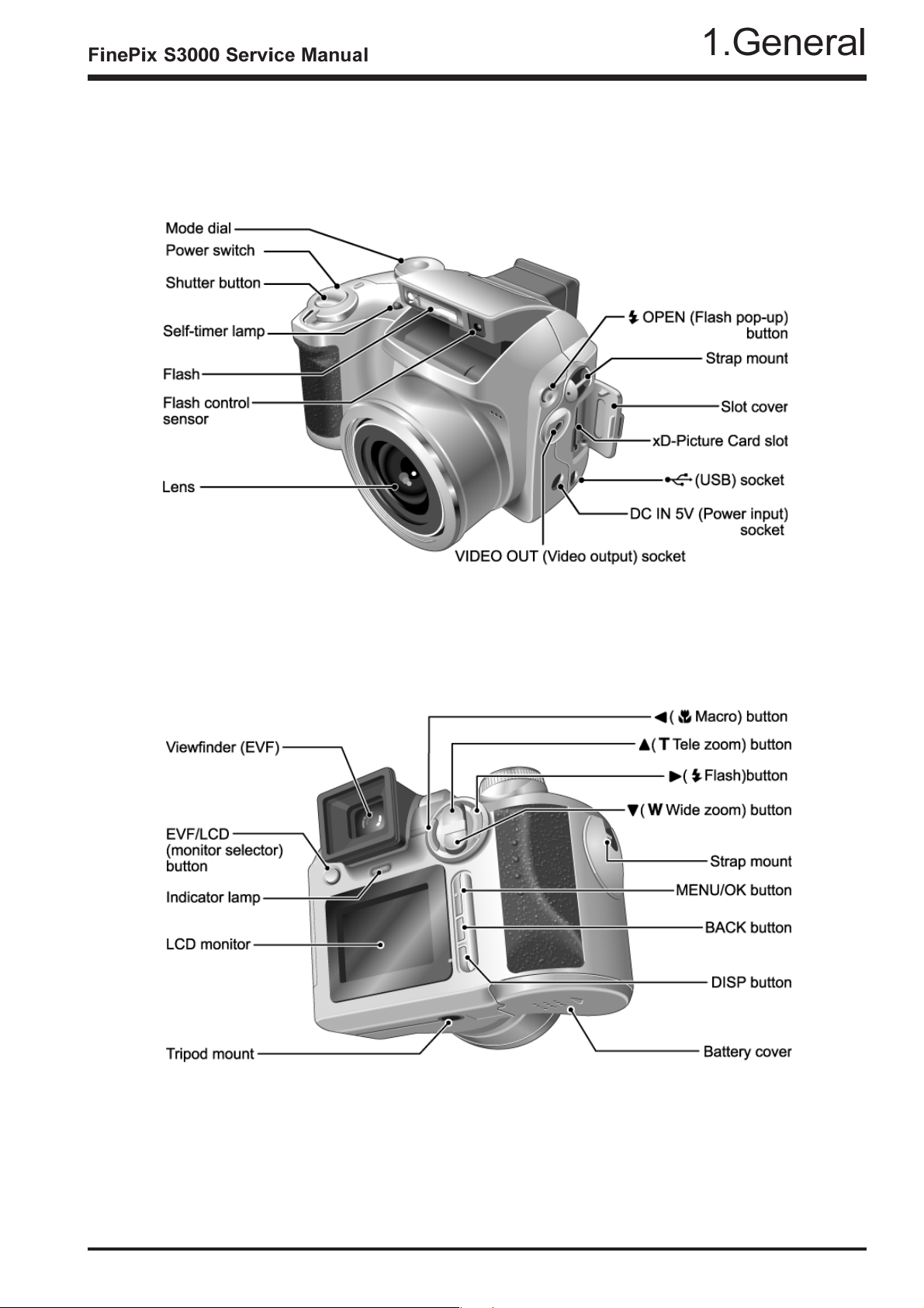
1-3.Names of External Components
7
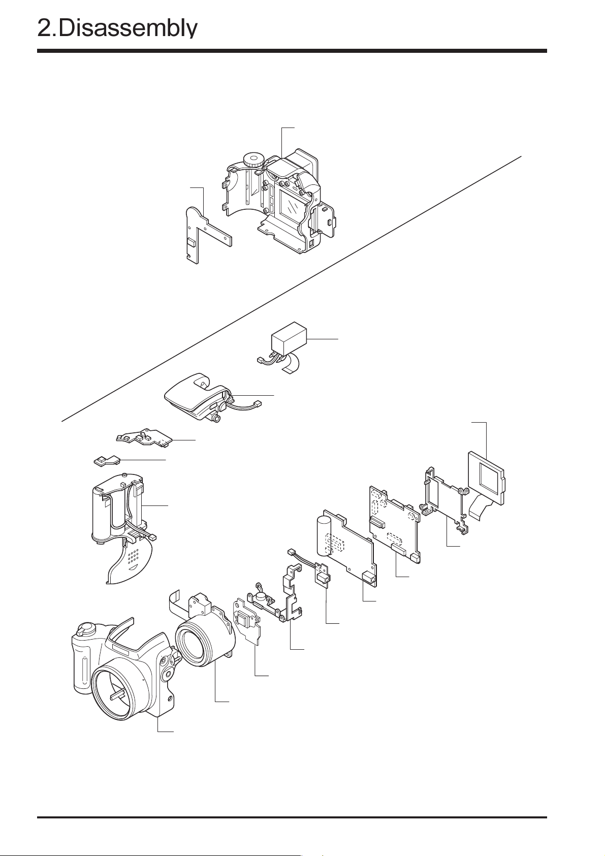
2. Disassembly
2-1.Names of Internal Parts
KEY PWB ASSY
FinePix S3000 Service Manual
CABI REAR ASSY
STROBE CONST
MSW PWB ASSY
RSW PWB ASSY
BATTERY HOLDER ASSY
EVF CONST
LCD CONST
LCD FRAME
MAIN PWB ASSY
DCST PWB ASSY
VCON PWB ASSY
MAIN FRAME ASSY
CCD PWB CONST
LENS UNIT
CABI FRONT ASSY
8

2-2.How to Disassemble the CABI R ASSY.
Remove in the order indicated by circled numbers.
(1) Change to the Manual camera mode.
(2) Remove three screws.
(3) Remove two special shape screws.(3ULR 1.5X5.0)
*Because the screws are special shape,use the
exclusive use jig driver(ZJ00583-100).
(4) Remove CABI REAR while pressing part A
in the direction of (3).
*Reassemble CABI REAR in the state of the Manual
camera mode.
<Step1>
2
A
1
A
4
2
3
(4) Remove connector (CN800).
<Step2>
4
9

2-3.Removing LCD ASSY / LCD FRAME.
Remove in the order indicated by circled numbers.
<Step1>
FinePix S3000 Service Manual
1
(1) Remove two screws.
(2) Remove the hook of LCD FRAME (two places),
and raise LCD ASSY in the direction of the arrow.
(3) Remove the lock of CN451, and remove LCD
ASSY/LCD FRAME to the direction of the arrow.
2
2
<Step2>
2-4.Removing EVF CONST.
Remove in the order indicated by circled numbers.
(1) Remove CN401.
(2) Remove CN402.
(3) Remove EVF CONST in the direction of the arrow.
3
<Step1>
1
3
2
10

2-5.Removing MAIN PWB ASSY.
Remove in the order indicated by circled numbers.
<Step1>
1
(1) Remove CN101 CN203, CN301, CN350and CN502.
(2) Remove MAIN PWB ASSY in the direction of the
arrow while removing the connector in A part.
2-6.Removing BATTERY HOLDER ASSY.
Remove in the order indicated by circled numbers.
(1) Peel off the UL tape, and do discharge.
1
<Step1>
2
A
1
1
(note)
Make the power lever a turning off mode.
(1) Raise BATTERY HOLDER ASSY in the direction
of the arrow.
(3) Remove CN601.
* Reassemble BATTERY HOLDER ASSY in the state
of the power lever off.
<Step2>
1
2
11

2-7.Removing DCST PWB ASSY.
Remove in the order indicated by circled numbers.
FinePix S3000 Service Manual
(1) Remove two screws.
(2) Remove CN701, CN702.
(3) Raise DCST PWB ASSY in the direction of the
arrow.
(4) Remove FPC of LENS CONST in the direction of
the arrow.
<Step1>
1
<Step2>
2
3
2-8.Removing LENS CONST.
Remove in the order indicated by circled numbers.
(1) Remove three screws.
(2) Remove CCD EARTH PLATE, EARTH PLATE.
(3) Remove two screws.
(4) Remove VCON PWB ASSY.
(5) Remove MAIN FRAME.
(6) Remove LENS CONST in the direction of the arrow.
<Step1>
3
4
1
4
2
5
6
12
2-9.Removing STROBE CONST/ST TOP.
4
5
6
Remove in the order indicated by circled numbers.
(1) Remove one screws.
(2) Remove STRAP BASE(R) in the direction
of the arrow.
1
2
<Step1>
<Step2>
(4) Remove one screws.
(5) Remove the hook of ST BUTTON, and pull out
ST BUTTON in the direction of the arrow.
(6) Remove STROBE CONST in the direction
of the arrow.
10
<Step3>
(7) Pull out two ST SHAFT.
7
(8) STOROBE must improve in pop-up.
(9) Remove two screws.
(10) Remove ST TOP in the direction of the arrow.
8
7
9
13

FinePix S3000 Service Manual
2-10.Removing MSW PWB ASSY and RSW PWB ASSY.
Remove in the order indicated by circled numbers.
(1) Remove one screw.
(2) Remove the hook of BATTERY HOLDER, and
remove RSW PWB ASSY and MSW PWB ASSY.
* Tighten the screw while joining MSW PWB ASSY to
(A), and confirm the thing which MSW PWB ASSY
and (A) are fit.
<Step1>
2
1
2
hook
A
MSW PWB ASSY
RSW PWB
2-11.Removing KEY PWB ASSY.
Remove in the order indicated by circled numbers.
(1) Remove four screws.
(2) Remove EARTH PLATE.
(3) Remove KEY PWB ASSY in the direction of the
arrow.
<Step1>
2
3
14
1

2-12.Removing CCD PWB CONST
2
1
LPF RUBBER
OPTICAL LPF
LPF MASK
LENS UNIT
CCD PWB
Remove in the order indicated by circled numbers.
(1) Remove tow screw.
(2) Remove the hook of CCD PWB CONST.
[Attention when CCD PWB CONST is exchanged. ]
Solder the WIRE HARNESS with new parts when you ex
change CCD PWB CONST.
Cover the solder part by the UL bond.(SC-608Z : FS00095-
100)
15

2-13.Location of Sheet parts.
FinePix S3000 Service Manual
2-13-1.FFC (CCD-MAIN)
FERRITE BEADS fixed to FFC.
Position at 15mm from MAINPWB side.
[Note]
Do not exceed Fold-Line of FFC.
EMI SHEET fixed to FFC.
Position at 6mm from MAINPWB side.
Match Fold-Line of EMI-SHEET to the left of FFC and paste it.
15mm
6mm
MAIN PWB
EMI SHEET
(FZ05597-100)
Fold line
FERRITE BEADS
(FLBZ120-100)
CAPTON TAPE
FFC
(CCD-MAIN)
(FZ04949-100)
CCD PWB
16
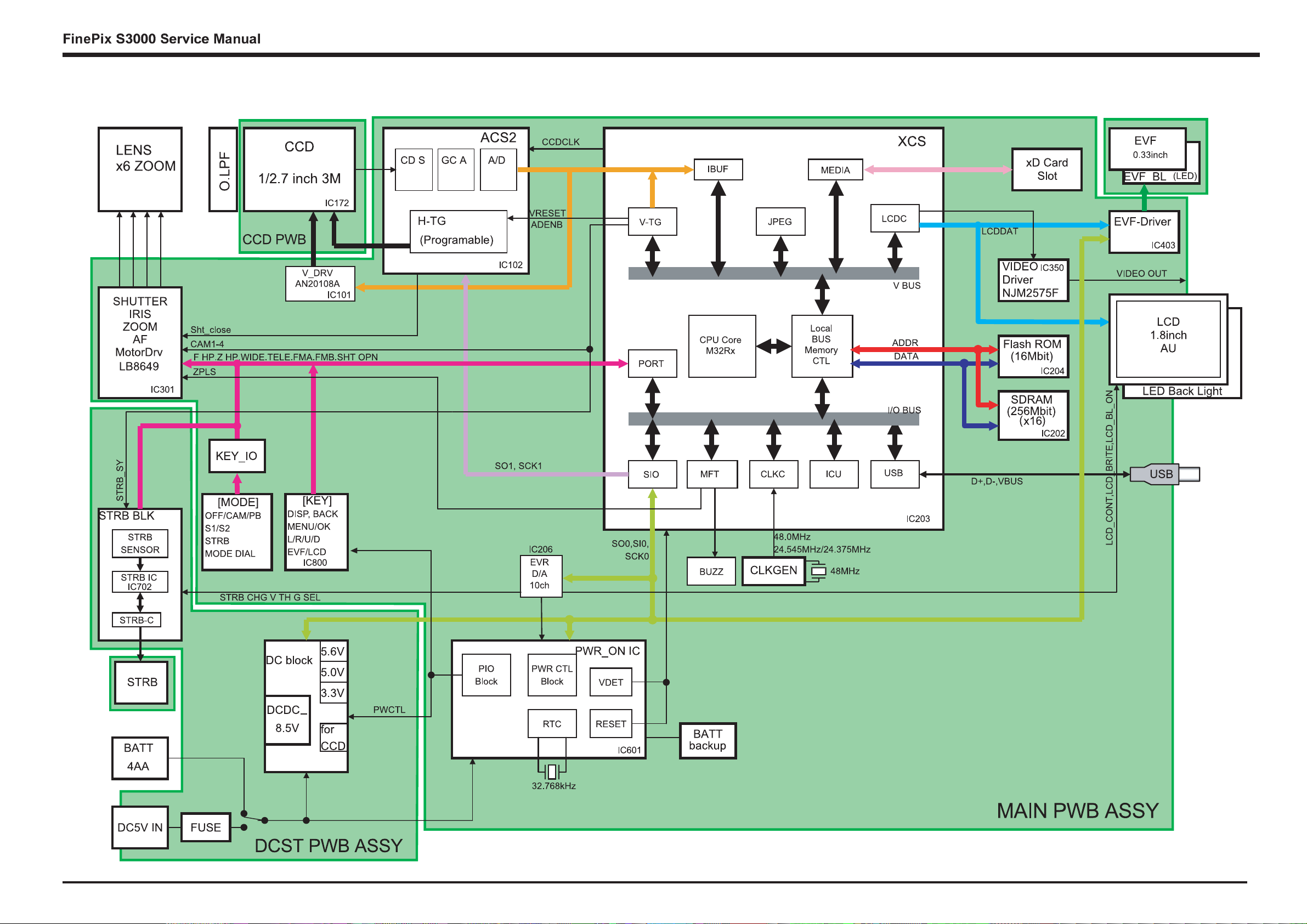
3.Schematics
3. Circuit Diagrams
3-1.Cautions
Precautions in parts replacement
Do not reuse detached electronic components. Use only new components.
The negative side of tantalum capacitors is weak against heat. Handle with care.
With the exception of Chemical capacitor and tantalum capacitors, the voltage of capacitors of a 50V or lower withstand voltage
is not labeled.
Unless specified, electronic component resistance is 1/16W.
K = 1000 , M = 1000 K
3.2 Names and Functions of Basic Blocks
Board Name Block name Function
CCD PWB CONST CCD BLOCK * CCD output
MAIN PWB ASSY CAM BLOCK * Analog to digital conversion of CCD output(IC102)
* CCD driver(IC101)
MOTOR BLOCK * Zoom/AF/shutter/iris drive(IC301)
POWER ON BLOCK * Power supply management(IC352)
EVF BLOCK * EVF control(IC403)
AUDIO BLOCK * Audio signal processing(IC501)
PROCESS BLOCK * USB communication(IC202)
* System control/SW detection management(IC202)
LCD BLOCK * LCD relay circuit
DCST PWB ASSY DCDC BLOCK * Each power supply generation(IC601)
FlashBLOCK * Flash luminescence processing(IC702)
MSW PWB ASSY MSW BLOCK * Operation SW(power supply/mode)
RSW PWB ASSY RSW BLOCK * Operation SW(shutter)
KEY PWB ASSY KEY BLOCK * Operation SW(EVF<->LCD/display/U<->D/cancellation/L<->R/OK)
VCON PWB ASSY VCON BLOCK * VIDEO(NTSC/PAL) output
17

FinePix S3000 Service Manual
3-3.Explanation of Functions of Important Blocks
3-3-1.Technical Overview
The FinePix S3000 incorporates a 1/2.7 -inch square pixel, primary color interline CCD of 3.34 million pixels(total).
An [xD picture card] is adopted as the recording media.
Change point from S304/3800.
ICs are the [ACS2 (IC102)] for CCD processing, [KEY IC (IC800)] that incorporates power supply management capabilities into operation
system processing, and system LSI [XCS (IC203)] that pakeged signal processing, LCD drive, V-TG functions.
Lose related parts of the microphone and the speaker of S304/3800. Video-out (NTSC/PAL) is added.
3-3-2.Explanation of Functions of Individual Blocks
(1) CCD Signal Processing/Picture-taking Blocks (CCD BLOCK and CAM BLOCK)
The analog signals output by the CCD (1/2.7 square pixel, primary color interline CCD of 3.34 million pixels[total] [IC172]) undergo color
compensation, adaptive interpolation, amplification (ACG) and signal mixing in the [ACS2 (IC102)] CCD signal processing IC. After that, the
signals are converted into 12-bit digital signals and sent to the [XCS (IC203)] system LSI.
This block has a vertical drive IC (IC101) for driving the CCD.
(2) Motor Block (MOTOR BLOCK)
Upon receiving commands from operating switches, the [XCS (IC203)] signal processing LSI manages the motor drive IC (IC301) so as to
control the motors for AF, shutter, zoom and iris.
(3) Image Signal Processing Block (PROCESS BLOCK)
Input Data from the CCD
The 10-bit digital image data (equivalent to 1H) output by the image unit (CCD/CAM BLOCK) is sent to the [XCS (IC203)] system LSI. It is
here converted into 32-bit (16-bit x 2) data by the internal buffer of the LSI, and image data of 2048 x 1536 pix per frame is temporarily stored
in the [SDRAM (IC202 256 Mbit X16)] of the LSI.
Also, the 32-bit image data input to this LSI is used for calculations by the [auto calculation unit] and sent to the [ACS2 (IC102)] CCD
processing IC of the CAM BLOCK so as to obtain a suitable AE, AWB and AF.
Recording Processing to the xD Card
The image data stored in the [SDRAM (IC202 256 Mbit X16)] of the [XCS (IC203)] system LSI is sent to the signal processing block one line
at a time where it undergoes unpack processing (32-bit >> 10-bit conversion, processing required prior to digital clamping, ( compensation,
10-bit >> 8-bit R/G/B conversion) and YC processing (8-bit digital R/G/B signal >> Y:Cb:Cr = 4:2:2). The 8-bit Y/Cb/Cr data is then sent to the
[internal buffer]. In the [internal buffer], data is arranged in a format that is easy to convert the 8-bit Y/Cb/Cr dat a into DCT. After going through
the [JPEG calculation unit] and the [media controller], it is recorded on the xD card.
Image Reproduction from the xD Card
The compressed image data from the xD card is sent to the [XCS (IC203)] system LSI as 8-bit image data. It is then sent to the [media control
unit] >> [DRAM unit] >> [SDRAM (IC202 256 Mbit X16)] >> [media controller] >> [JPEG calculation unit] >> [signal processing unit]. The
[signal processing unit] does the post-processing of converting the 8-bit Y/Cb/Cr signals into 8-bit R/G/B signals. At the same time, it weighs
the text display signal and displays the text on the LCD UNIT via the [LCD controller].
Picture-taking system adjustment data is stored in the FLASH ROM (IC204).
(4) LCD UNIT
The digital signal sent from the [XCS (IC203)] system LSI is sent to the drive IC of the LCD UNIT via the processing unit on the LCD FPC of
the LCD UNIT, where [LCD drive] and [LCD panel tonal control] are performed.
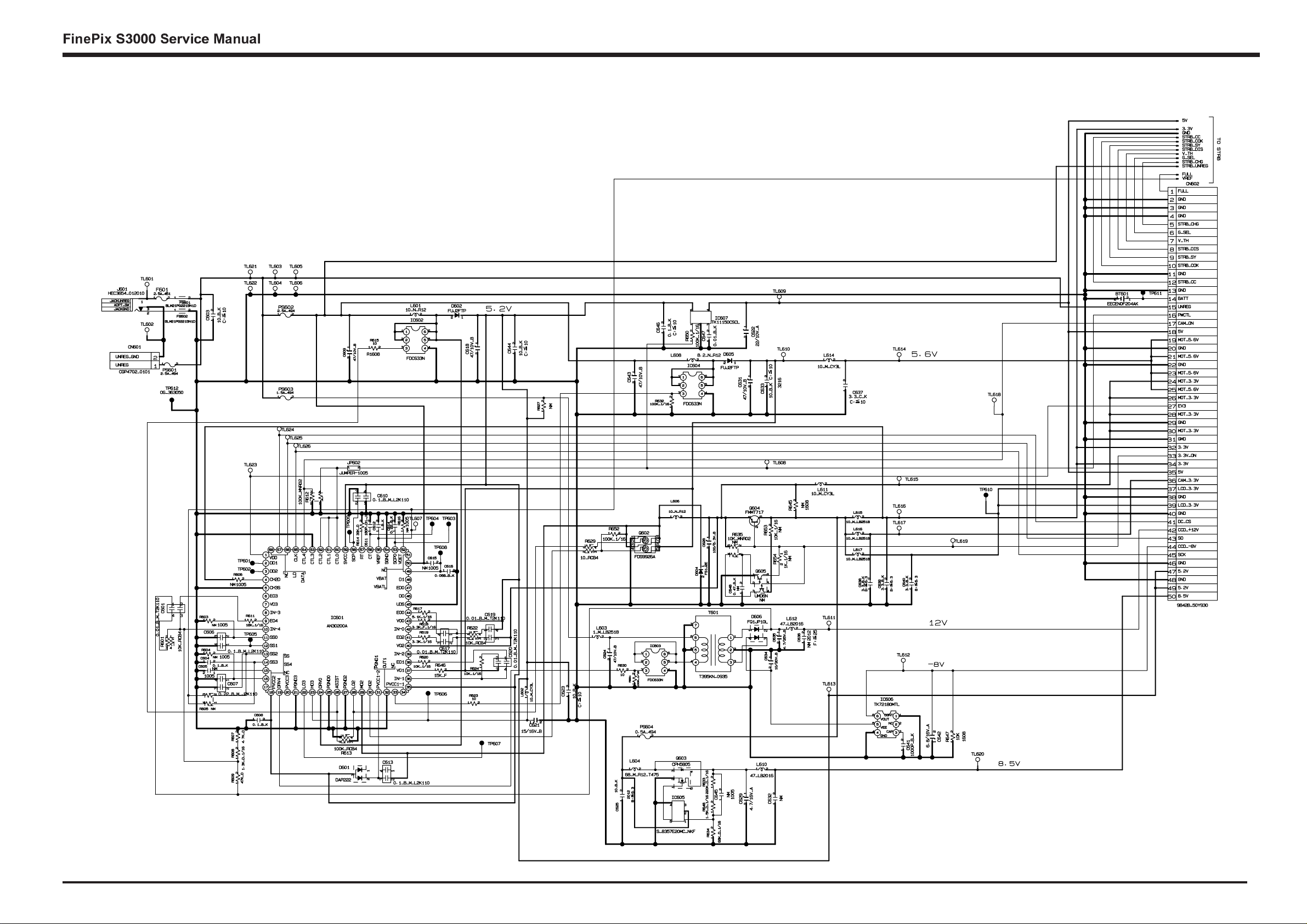
(5) Power Supply Block (DCDC BLOCK)
The power supply block is built around the DC IC (IC601). It generates the below power supplies and supplies them to the individual blocks.
5 V [(IC501), EVF-Drv(IC403), STRB IC (IC702),]
3.3 V [XCS (IC203), ACS2 (IC102), V-Drv (IC101), FLASH ROM (IC204), STRB IC (IC702), MOTOR Drv (IC301),
SDRAM(IC202), KEY IC (IC800), KEY IO(IC501/502), xD Picture Card, MAIN PWB, KSW PWB,MSW PWB]
EV3 [MAIN PWB, KEY IC (IC800)]
A3.3V [XCS (IC203), VIDEO Drv (IC350), CLK GEN (IC201), EVR (IC206), EVF-Drv(IC403), MAIN PWB, MSW PWB, LCD]
12 V [CCD (IC172), V Drv (IC101)]
-8 C [CCD (IC172), V Drv (IC101)]
18
3.Schematics
3-4.Block Diagram
19

3.Schematics
DCDC PWB
RSW PWB
A
A
MOTOR R
A
MSW PWB
LENS
FPC
STROBE CONST
A
A
A
A
A
A
V_CON PWB
CCD PWB
EVF UNIT
KSW PWB
LCD UNIT
STRB_SW UNIT
MAIN PWB
xD CARD
USB
3-5.Overall
FinePix S3000 Service Manual
1.XE+
STRB
C-JA CK
JACKUNREG
DPT_SW
JACKGND
BATTER Y
STROBE CONST
2.TRIG GER
3.XE-
4.TRI GGER_C
UNREG_ GND
UNREG
1.PT
2.PT_GND
5V
3.3V
GND
STRB_CC
STRB_COK
STRB_SY
STRB_DI S
Y_TH
G_SEL
STRB_CHG
STRB_UNREG
FULL
VREF
DCDC PWB
RSW PWB
1.GND
2.GND
RSW
3.S2
4.S1
5.GND
6.GND
STRB_SW UNIT
DCDC
MSW
MSW PWB
1.FULL
2.GND
3.GND
4.GND
5.STRB_CHG
6.G_SEL
7.V_TH
8.STRB_DIS
9.STRB_SY
10.STRB_COK
11.G ND
12.STRB_CC
13.GND
14.BATT
15.UNREG
16.PWCTL
17.CAM_ON
18.5V
19.MOT _5.6V
20.GND
21.MOT _5.6V
22.GND
23.MOT _5.6V
24.MOT _3.3V
25.MOT _5.6V
26.MOT _3.3V
27.EV3
28.MOT _3.3V
29.GND
30.MOT _3.3V
31.GND
32.3.3V
33.3.3V_ON
34.3.3V
35.5V
36.CAM_ 3.3V
37.LCD _3.3V
38.GND
39.LCD _3.3V
40.GND
41.DC_CS
42.CCD_+12V
43.SO
44.CCD_-8V
45.SCK
46.GND
47.5.2V
48.GND
49.5.2V
50.8.5V
1.PW_SW
2.EV3
3.GND
4.PLAY
5.A3.3V
6.S2
7.S1
8.GND
9.MODE2
10.MOD1
11.5 V
12.LED _ST
3.3V
3.3V
5.2V
EV3
GND
SEL0
SEL1
CSEN
EVR_CS
DC_CS
IN D0
IN D1
KEY_IO
1.NC
2.NC
3.STRB_SW
4.GND
5.NC
6.NC
V_DET
USB
VBUS
DD+
GND
FGND
3.3V
GND
VOUT
VIDEO_ON
VIDEO
-8V
CCD_
1.GND
2.CARD
CCD_+12V
CAM_ 3.3V
xD CARD
3.R/B
4.RE
5.CE
6.CLE
7.ALE
8.WE
9.WP
10.GND
MAIN PWB
PROCESS
Y
GND OFD_CONT
DE NB
XOFD
STR B_S
CCD_DI
CCD_LD
CAM MOTO
11.D 0
XCL K
12.D1
13.D2
DCK
CCD_STB
14.D3
15.D4
CCD_CL K
CCDDT[0]
16.D5
17.D6
CCDDT[1]
CCDDT[2]
18.D7
19.VCC
CCDDT[3]
CCDDT[4]
20.VCC
CCDDT[5]
CCDDT[6]
CCDDT[7]
CCDDT[8]
CCDDT[9]
VRESET
1.GND
2.VCC
3.VGL
LCD_3.3V
3.3V
GND
LCD_BL_ON
LCD_BRIGHT
LCD_CONT
LCDDA T[2]
LCDDA T[3]
LCDDA T[4]
LCDDA T[5]
LCDDA T[6]
LCDDA T[7]
LCDDVD
LCDDHD
LCDCLK
LCD_ON
OCONT
4.VGH
5.FRP
6.COM
7.DH V
8.FB
9.SHL
MOT5. 6V
MOT3. 3V
3.3V
GND
CAM1
CAM2
CAM3
CAM4
SHT_OPN
FMA1
FMA2
FMB1
FMB2
WIDE
TELE
Z_HP
F_HP
Z_PLSZMPS_I
RI S_SWL
FMSP
LCD UNIT
10.STB
11.VCC
12.SHD B
13.AGND
14.VL ED+
15.VL ED-
16.AVDD
17.HSYN C
18.YSYN C
19.DCLK 20.DS5
21.DS4
22.DS3
23.DS2
24.DS1
25.DS0
26.GRB
27.U/D
28.GND
29.AVDD1
30.AGND
LCD
3.3V
EV3
UNREG
GND
PW_SW
PWCTL
3.3V_ON
BU3
KEY_SI
KEY_SCLK
KEY_SO
CCD_ON
NT_PAL
CT
VREF_END
RESET
CARD_ON
EVF_ BL_ON
EVF_ ON
VCLK_ON
STRB_COK
STRB_FULL
KO2
LED_S T
PW_SW
KEY_CS
3V_ON
MOT_5.6V
5V
3.3V
GND
8.5V
LCDDA T[0]
LCDDA T[1]
LCDDA T[2]
LCDDA T[3]
LCDDA T[4]
LCDDA T[5]
LCDDA T[6]
LCDDA T[7]
LCDDVD
LCDDHD
LCDCLK
EVF_ CS
KEY_SCLK
KEY_SI
LCD_ON
KEY_IC
EVF_ ON
EVF8.5V_ON
EVF_ BL_ON
EVF
1.KO0
2.KO1
3.KI0
4.KI1
5.KI2
6.KI3
7.GND
8.LED _G
9.LED _R
10.3.3V
F_LON
Z_LON
1.COM
2.CKV1
3.CKV2
4.STV
5.XSTV
6.XENB
7.END
8.CSV
9.VBB
10.DSD
11.X DSG
12.DSG
13.B
14.R
15.G
16.CSH
17.VDD
18.CKH2
19.CKH1
20.VSS
21.STH
22.XSTH
1.ANODE
2.CATHODE
KSW PWB
KSW
EVF UNIT
DET
GND
VBS
VCON
1.DET
2.GND
3.VBS
22.GND
21.VOUT
20.GND
19.CCD_+15V
18.GND
17.RG
16.H2
15.H1
14.GND
A
8.V3B
7.V4
9.V3
6.V5A
13.CSUB
12.SUB
11.V 1
10.V2
5.V5B
4.V6
3.VL
2.GND
1.GND
1.ZPI_C
2.ZPI_E
3.3V
4.SHUTOU T1
5.SHUTOU T2
6.MID IM1-
7.MID IM2 +
8.SML IM1-
9.SML IM2 +
10.FM/ A
11.F M /B
12.FM A
13.FM B
14.FPI_C
15.FPI_E
16.3V
17.ZPOSI_C
18.ZPOSI_E
19.ZM1+
20.ZM2-
VIDEO-JAC K
CCD PWB
CCD LENS
FPC
V_CON PWB
20
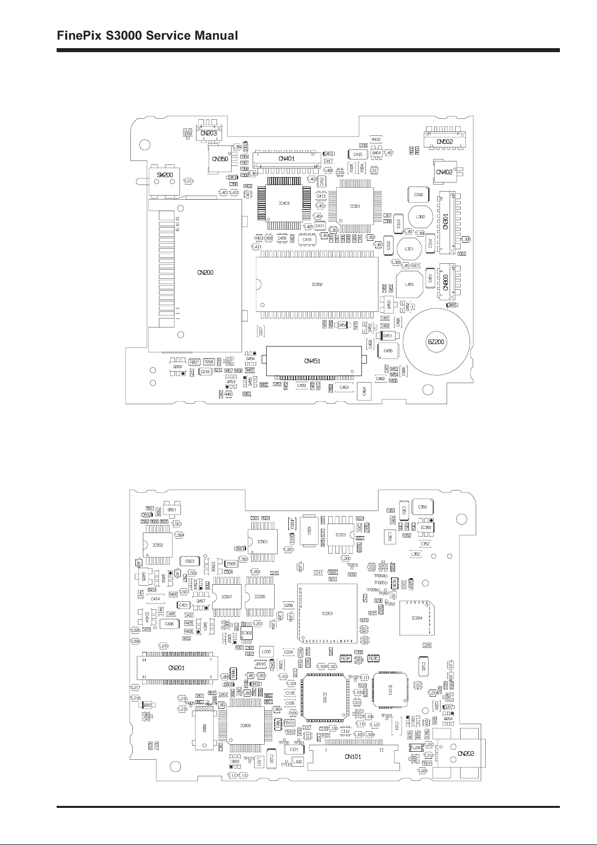
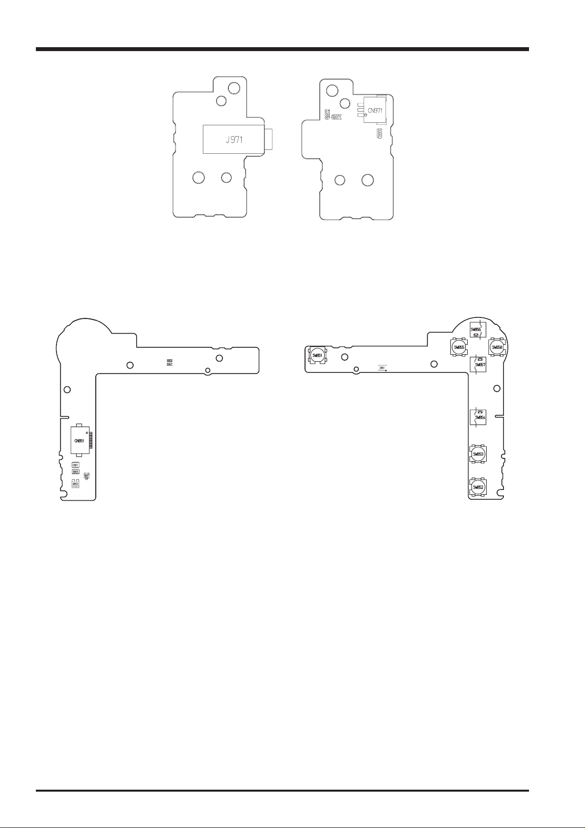
3-6.Mounted Parts Diagrams
3-6-1.MAIN PWB ASSY Component Location
<SIDE-A>
3.Schematics
<SIDE-B>
21

3.Schematics
3-6-2.DCDC PWB ASSY Component Location
<SIDE-A>
FinePix S3000 Service Manual
<SIDE-B>
22
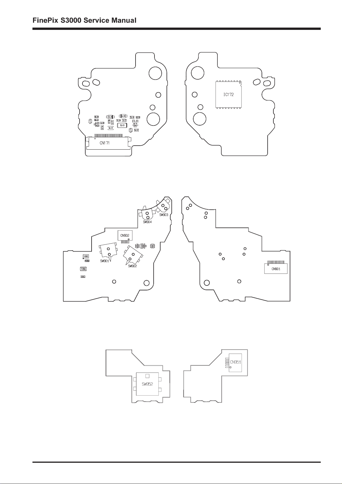
3-6-3.CCD PWB CONST Component Location
3.Schematics
<SIDE-A>
3-6-4.MSW PWB UNIT Component Location
<SIDE-A>
<SIDE-B>
<SIDE-B>
3-6-5.RSW PWB UNIT Component Location
<SIDE-A>
<SIDE-B>
23
3.Schematics
3-6-6.VCON PWB UNIT Component Location
<SIDE-A> <SIDE-B>
3-6-7.KEY PWB UNIT Component Location
FinePix S3000 Service Manual
<SIDE-A>
<SIDE-B>
24
3.Schematics
3-7.Circuit Diagrams
3-7-1.DCDC Block Circuit
25
 Loading...