

FUJIFILM FinePix S20 PRO Service Manual
SERVICE MANUAL
US/CA/EU/EG/GE/AS-Model
WARNING
THE COMPORNENTS IDENTIFIED BY THE MARK “ ” ON THE SCHEMATHIC
DIAGRAM AND IN THE PARTS LIST ARE CRITICAL FOR SAFETY.
PLEASE REPLACE ONLY BY THE COMPONENTS SPECIFIED ON THE SCHEMATHIC
DIAGRAM AND IN THE PARTS LIST.
IF YOU USE WITH PART NUMBER UN-SPECIFIED, IT MAY RESULT IN A FIRE AND AN
ELECTORICAL SHOCK.
FUJI PHOTO FILM CO.,LTD.
Printed in Japan 2004.02(T.S.)
Ref.No.:ZM00537-101

SAFETY CHECK-OUT
After correcting the original problem, perform the following
safety check before returning the product to the customer.
FinePix S20Pro Service Manual
1. Check the area of your repair for unsoldered or
poorly soldered connections. Check the entire
board surface for solder splasher and bridges.
2. Check the interboard wiring to ensure that no
wires are “pinched” or contact high-wattage
resistors.
3. Look for unauthorized replacement parts, particularly transistors, that were installed during a
previous repair . Point them out to the customer
and recommend their replacement.
4. Look for parts which, though functioning, show
obvious signs of deterioration. Point them out to
the customer and recommend their replacement.
5. Caution:
For continued protection against fire
2.5A 125/250V
2.5A 125/250V
RISK OF FIREREPLACE FUSE
AS MARKED
hazard, replace only with same
type 2.5 amperes 125/250 volts
fuse.
Attention:
Afin d’assurer une protection
permanente contre les risques
d’incendie, remplacer uniquement
par un fusible de meme, type 2.5
amperes, 125/250 volts.
6. Warning:
To reduce the electric shock, be
WARNING!
HIGH VOLTAGE
careful to touch the parts.
2

FinePix S20Pro Service Manual
TABLE OF CONTENTS
1.General
1-1. Product specification .........................................................4
1-2. Names of External Components ...................................... 8
2. Disassembly
2-1. Names of Internal Components..................................... 10
2-2. How to remove R CABI CONST .................................... 11
2-3. Decomposition of R CABI CONST................................. 12
2-4. How to remove LCD ASSY ........................................... 13
2-5. How to remove TOP CABI CONST................................ 14
2-6. Decomposition of TOP CABI CONST ............................ 18
2-7. How to remove LCD FRAME CONST............................ 20
2-8. Decomposition of LCD FRAME CONST ........................ 21
2-9. Decomposition of MAIN PWB ASY ............................... 21
2-10. How to remove SHEET FRAME ................................... 22
2-11. How to remove BATTERY LID .................................... 22
2-12. How to remove BATTERY HOLDER UNIT.................. 23
2-13. How to remove CAM PWB ASSY ............................... 23
2-14. How to remove LENS FRAME ..................................... 24
2-15. How to remove LENS CONST ..................................... 24
2-16. How to remove LENS CABI ASSY ............................. 25
2-17. How to remove SIDE MODULE UNIT ........................... 26
2-18. How to remove AF SENSOR UNIT.............................. 27
3. Schematics
3-1. Cautions ........................................................................... 28
3-2. Basic Block Names and Functions ............................... 28
3-3. Functions of Primary Blocks ......................................... 29
3-3-1. Technical Outline ................................................. 29
3-3-2. CAM Board Block Functions .............................. 29
3-3-3. MAIN Board Block Functions ............................. 29
3-3-4. DCST Board Block Functions............................. 29
3-4. Block Diagram.................................................................. 30
3-5. Overall connection Diagram .......................................... 31
3-6. CCD BLOCK Schematic Diagram .................................. 32
3-7. CAMERA BLOCK Schematic Diagram .......................... 33
3-8. PROCESS BLOCK Schematic Diagram ......................... 34
3-9. DCDC BLOCK Schematic Diagram ................................ 35
3-10. LCD-EVF BLOCK Schematic Diagram........................ 36
3-11. KEY SW BLOCK Schematic Diagram ......................... 37
3-12. MOTOR BLOCK Schematic Diagram........................... 38
3-13. POWER ON BLOCK Schematic Diagram .................... 39
3-14. FLASH BLOCK Schematic Diagram............................ 40
3-15. USB2.0 BLOCK Schematic Diagram ........................... 41
3-16. IEEE1394 BLOCK Schematic Diagram........................ 42
3-17. AUDIO BLOCK Schematic Diagram ............................ 43
3-18. MAIN I/F BLOCK Schematic Diagram.......................... 44
3-19. MC-FPC BLOCK Schematic Diagram .......................... 45
3-20. BL BLOCK Schematic Diagram ................................... 45
3-21. CCD FPC ASSY Component Locations...................... 46
3-22. CAM PWB ASSY Component Locations.................... 46
3-23. KEY PWB ASSY Component Locations .................... 47
3-24. MAIN PWB ASSY Component Locations................... 48
3-25. DCST PWB ASSY Component Locations .................. 50
TABLE OF CONTENTS
Page Page
4. Adjustments
4-1. Adjustment Procedure of Parts Replacement ............. 52
4-2. Measuring Devices ......................................................... 53
4-3. Jigs.................................................................................... 53
4-5. Adjustment environment ................................................ 54
4-4. Jig Connections ............................................................... 54
4-4. Calibration method of pattern box ................................ 54
4-7. Installing and Starting the Adjustment Software ....... 57
4-8. Initializing the Adjustment Software ............................ 57
4-6. Installing the Jig Drivers on the PC............................... 57
4-9. Starting the Adjustment Software ............................... 60
4-10. [R] : Flash memory reset ............................................. 63
4-11. [F9]: AF Sensor Adjustment ........................................ 65
4-12. [F4] : CCD data input .................................................... 70
4-13. [F5] : Camera adjustment............................................. 72
4-14. [F6] : AF adjustment ..................................................... 75
4-15. [F7] : Flash adjustment................................................. 78
4-16. [F1] : Battery voltage adjustment ............................... 80
4-17. [F11] : VIDEO Adjustment ............................................ 83
4-18. [F8] : Firmware Download ........................................... 85
4-19. [F12] : End Setting ........................................................ 87
5. Inspection
5-1. Required Measuring Equipment .................................... 92
5-2. Connection of Measuring Equipment ........................... 92
5-3. Inspection and Factory Settings .................................. 92
6. Parts List
6-1. Packing and Accessories .............................................. 94
6-1-1. For US model ........................................................ 94
6-1-2. For CA model........................................................ 95
6-1-3. For EU model ........................................................ 96
6-1-4. For EG model ........................................................ 97
6-1-5. For GE model ........................................................ 98
6-1-6. For AS model ........................................................ 99
6-2 . Ca b in e t F b l oc k (A L L- M OD E L) .................................... 1 0 0
6-3. Internal parts (ALL-MODEL) ........................................ 101
6-4. Cabinet R block (ALL-MODEL).................................... 102
6-5. External Parts ................................................................ 103
6-5-1. External Parts (US/CA-MODEL)....................... 103
6-5-2. External Parts (EU/EG/GE/AS-MODEL)........... 104
6-6. Electrical parts .............................................................. 105
7. Appendix
7-1. Function of display for Firmware Version ............... 106
7-2. List of Related Technical Updates Issued ................ 107
3

1. General
FinePix S20Pro Service Manual
1.General
1-1. Product specification
System
Model Digital camera FinePix S20Pro
Effective pixels 6.2 million (S-pixel: 3.1million, R-pixel: 3.1million) pixels
CCD 1/1.7-inch Super CCD SR
Total 6.7 million (S-pixel: 3.35 million, R-pixel: 3.35 million) pixels
Storage media xD-Picture Card (16/32/64/128/256/512 MB)
Microdrive (340 MB/1 GB)
File format Still image: DCF-compliant
Compressed: Exif Ver.2.2 JPEG, DPOF-compatible
* Design rule for Camera File System compliant DPOF compatible
Uncompressed: CCD-RAW (RAF)
Movie: AVI format, Motion JPEG
Audio: WAVE format, Monaural sound
Number of recorded pixels
1280 × 960 pixels ( / / / / )
Lens Super EBC Fujinon 6× zoom lens, F2.8-F3.1
Focal length 7.8 mm-46.8 mm (Equivalent to 35 mm-210 mm on a 35 mm camera)
Focus TTL contrast-type, Auto focus, Manual focus
Focal range Normal: Wide-angle: Approx. 50 cm (1.6 ft.) to infinity
Shutter speed /SP: 1/4 sec. to 1/2000 sec.
Aperture F2.8 to F8 10 steps in 1/3 EV increments Manual/Auto selectable
Sensitivity : Equivalent to ISO160-800
(resolution is set at / / for shots taken at ISO 800.)
Photometry TTL 64-zones metering Multi, Spot, Average
Exposure control Program AE ( , P, SP), Shutter-priority AE, Aperture-priority AE, Manual expo-
Exposure compensation
White balance Auto ( , SP)
Viewfinder 0.44-inch 235,000 pixels electronic viewfinder Approx. 100% coverage
LCD monitor 1.8-inches, 118,000-pixel low temperature polysilicon TFT, Approx. 100% coverage
Flash Type Auto flash using flash control sensor
Self-Timer 2 sec./10 sec.
Video output NTSC/PAL selectable
Still image: 2832 × 2128 pixels/ 2048 × 1536 pixels/1600 × 1200 pixels/
Movie: 640 × 480 pixels (30 frames per second with monaural sound)
320 × 240 pixels (30 frames per second with monaural sound)
Telephoto: Approx. 90 cm (3.0 ft.) to infinity
Macro: Approx. 10 cm (3.9 in.) to 80 cm (2.6 ft.)
Super Macro: Approx. 1 cm (0.4 in.) to 20 cm (7.9 in.)
SP (Night scene mode only): 3 sec. to 1/250 sec.
P/S/A: 3 sec. to 1/1000 sec. M: 15 sec. to 1/10000 sec. Bulb (Up to 15 sec.)
Manual: Equivalent to ISO200/400/800/1600
sure
-2 EV to +2 EV (13 steps in 1/3 EV increments)
Manual modes, 9 positions can be selected (P, S, A, M)
Effective range: Wide-angle: Approx. 0.3 m-8.5 m (1.0 ft.-27.9 ft.)
(Approx. 0.3 m-0.8 m (1.0 ft.-2.6 ft.): Macro)
Telephoto: Approx. 0.9 m-7.9 m (3.0 ft.-25.9 ft.)
Flash modes: Auto, Red-Eye Reduction, Forced Flash, Suppressed Flash, Slow
Synchro, Red-Eye Reduction + Slow Synchro
Input/Output Terminals
A/V output socket 2.5 mm dia. jack
USB (mini-B) socket
DC Input Socket for specified AC Power adapter AC-5VH/AC-5VHS (sold separately)
Accessory shoe Hot shoe
For file transfer to a computer
4
FinePix S20Pro Service Manual
1. General
Power Supply and Others
Power supply Use one of the following:
• 4× AA-size alkaline batteries
• 4× AA-size Ni-MH (Nickel-Metal Hydride) batteries (sold separately)
• AC Power Adapter AC-5VH/AC-5VHS (sold separately)
Conditions for use
Guide to the number
of available frames
for battery operation
Camera dimensions 121.0 mm × 81.5 mm × 97.0 mm/4.8 in. × 3.2 in. × 3.8 in.
(W × H × D) (not including accessories and attachments)
Camera mass (weight)
Weight for photography
Accessories 16 MB, xD-Picture Card (1) Included with: Anti-static case (1)
Optional Accessories xD-Picture Card
Temperature: 0oC to +40oC (+32oF to +104oF) 80% humidity or less (no condensation)
Media type
xD-Picture Card
Microdrive
Battery Type
Using LCD monitor
Using EVF
Using LCD monitor
Using EVF
Alkaline batteries
Approx. 220 frames
Approx. 230 frames
Approx. 210 frames
Approx. 220 frames
Ni-MH batteries
HR-3UF (2100)
Approx. 350 frames
Approx. 360 frames
Approx. 320 frames
Approx. 330 frames
The number of available frames for battery operation given here is a guide to the
number of consecutive shots that can be taken under FUJIFILM test conditions.
•
Batteries used: alkaline batteries bundled with the camera fully charged Ni-MH batteries
• Shooting conditions: Measured at normal temperature with 50% flash use
• Note: Because the number of available frames that can be taken varies depending on the capacities of alkaline batteries and the amount of charge in NiMH batteries, the figures given here for the number of frames that can be
taken using batteries are not guaranteed. At low temperatures, fewer pictures can be taken when the camera is running on batteries.
500 g/17.6 oz. (not including accessories, batteries, xD-Picture Card and Microdrive)
Approx. 600 g/21.2 oz. (including batteries and xD-Picture Card)
AA-size alkaline batteries (4) Shoulder Strap (1)
Protective cover (2) Metal strap clip (2) Clip attaching tool (1)
Lens cap (1) Lens cap holder (1)
A/V (audio-visual) cable (included) (1) (plug (2.5 mm dia.) to pin-plug cable × 2)
USB cable (mini-B) (1) CD-ROM (1) Software for FinePix SX
Owner’s Manual (1)
DPC-16 (16 MB)/DPC-32 (32 MB)/DPC-64 (64 MB)/DPC-128 (128 MB)/
DPC-256 (256 MB)/DPC-512 (512 MB)
AC Power Adapter AC-5VH/AC-5VHS Fujifilm Rechargeable Battery 2HR-3UF
Fujifilm Battery charger with Battery BK-NH/BK-NH2 (With Euro type or UK type plug)
SC-FX602
Wide conversion lens WL-FX9/WL-FX9B Teleconversion lens TL-FX9/TL-FX9B
Image Memory Card Reader DPC-R1
• Compatible with Windows 98/98 SE, Windows Me, Windows 2000 Professional, Windows XP or iMac, Mac OS 8.6 to 9.2.2, Mac OS X (10.1.2 to
10.2.2) and models that support USB as standard.
• Compatible with xD-Picture Card of 16 MB to 512 MB, and SmartMedia of
3.3V, 4 MB to 128 MB.
PC Card Adapter DPC-AD
• Compatible with xD-Picture Card of 16 MB to 512 MB, and SmartMedia of
3.3V, 2 MB to 128 MB.
CompactFlash Card Adapter DPC-CF
• Windows 95/98/98 SE/Me/2000 Professional/XP
• Mac OS 8.6 to 9.2/X (10.1.2 to 10.1.5)
Standard number of frames per Media
Quality
Number of recorded pixels
DPC-16 (16 MB) 5
DPC-32 (32 MB)
DPC-64 (64 MB)
DPC-128 (128 MB)
DPC-256 (256 MB)
Microdrive 1 GB
Fine
x
2832 2128
10
21
42
86
172 343 651 818 1101 39DPC-512 (512 MB)
117 234 445 559 752 26Microdrive 340 MB
353 698 1313 1642 2190 80
Normal
10
21
42
85
171
x
2048 1536
19
40
81
162
325
x
1600 1200
25
50
101
204
409
x
1280 960
33
68
137
275
550
x
2832 2128
1
2
4
9
19
5

1. General
FinePix S20Pro Service Manual
Standard recording Times for Media
Quality mode
Number of recorded pixels
DPC-16 (16 MB)
DPC-32 (32 MB)
DPC-64 (64 MB)
DPC-128 (128 MB)
DPC-256 (256 MB)
* The number of available frames, recording time or file size varies slightly de-
pending on the subjects photographed. Note also that the difference between
standard number of frames and the actual number of frames is greater for media
with higher capacities.
(30 fps)
640 480
13 sec.
27 sec.
55 sec.
111 sec.
223 sec.
7.4 min. 14.6 min.DPC-512 (512 MB)
5.0 min. 10.0 min.Microdrive 340 MB
15.3 min. 30.1 min.Microdrive 1 GB
(30 fps)
320 240
26 sec.
54 sec.
109 sec.
219 sec.
7.3 min.
6

FinePix S20Pro Service Manual
1. General
Explanation of Terms
AF/AE Lock : On the FinePix S7000, pressing the shutter button down half way locks the focus
and exposure settings (AF and AE lock). If you want to focus on a subject that is
not centered in the frame or change the picture composition after the exposure is
set, you can obtain good results by changing the composition after the AF and
AE settings are locked.
Auto Power Save Function :
Deactivated batteries: Leaving an Ni-MH battery unused in storage for a long period may cause a rise in
DPOF: Digital Print Order Format
EV: A number that denotes Exposure Value. The EV is determined by the brightness
Frame rate (fps) : The frame rate refers to the number of images (frames) that are photographed or
JPEG : Joint Photographics Experts Group
Memory effect: If an Ni-MH battery is repeatedly charged without first being fully discharged, its
Motion JPEG: A type of AVI (Audio Video Interleave) file format that handles images and sound
PC Card: A generic term for cards that meet the PC Card Standard.
PC Card Standard: A standard for PC cards determined by the PCMCIA.
PCMCIA: Personal Computer Memory Card International Association (US).
Smear : A phenomenon specific to CCDs whereby white streaks appear on the image
WAVE : A standard format used on Windows systems for saving audio data. WAVE files
White Balance: Whatever the kind of the light, the human eye adapts to it so that a white object
Exif Print: Exif Print Format is a newly revised digital camera file format that contains a
If the camera is not used in any way for 30 seconds, this function turns
features such as the LCD monitor off (Sleep mode) to prevent battery depletion
and the waste of power when the AC power adapter is connected. If the camera is
then left unused for a further period, the Auto Power Save function turns the camera off. This period can be set to 2 minutes or 5 minutes on this camera.
The Auto Power Off function does not operate in PC mode, during automatic
playback, or if it is disabled during setup.
the level of substances that inhibit current flow inside the battery and result in a
dormant battery. A battery in this state is referred to as deactivated.
Because current flow is inhibited in a deactivated Ni-MH battery, the battery’s
original level of performance cannot be achieved.
DPOF is a format used for recording information on a storage media (image
memory card, etc.) that allows you to specify which of the frames shot using a
digital camera are to be printed and how many prints are made of each image.
of the subject and sensitivity (speed) of the film or CCD. The number is larger for
bright subjects and smaller for dark subjects. As the brightness of the subject
changes, a digital camera maintains the amount of light hitting the CCD at a
constant level by adjusting the aperture and shutter speed.
When the amount of light striking the CCD doubles, the EV increases by 1. Likewise, when the light is halved, the EV decreases by 1.
played back per second. For example, when 10 frames are continuously photographed in a 1-second interval, the frame rate is expressed as 10 fps.
For reference, TV images are displayed at 30 fps.
A file format used for compressing and saving color images. The higher the compression rate, the greater the loss of quality in the decompressed (restored) image.
performance may drop below its original level. This is referred to as the “memory
effect”.
as a single file. Images in the file are recorded in JPEG format. Motion JPEG can
be played back by QuickTime 3.0 or later.
when there is a very strong light source, such as the sun or reflected sunlight, in
the photography screen.
have the “.WAV” file extension and the data can be saved in either compressed or
uncompressed format. Uncompressed recording is used on this camera.
WAVE files can be played back on a personal computer using the following software:
Windows: MediaPlayer
Macintosh: QuickTime Player
still looks white. On the other hand, devices such as digital cameras see a white
subject as white by first adjusting the color balance to suit the color of the ambient light around the subject. This adjustment is called matching the white balance. A function that automatically matches the white balance is called an Automatic White Balance function.
variety of shooting information for optimal printing.
*QuickTime 3.0 or later
7
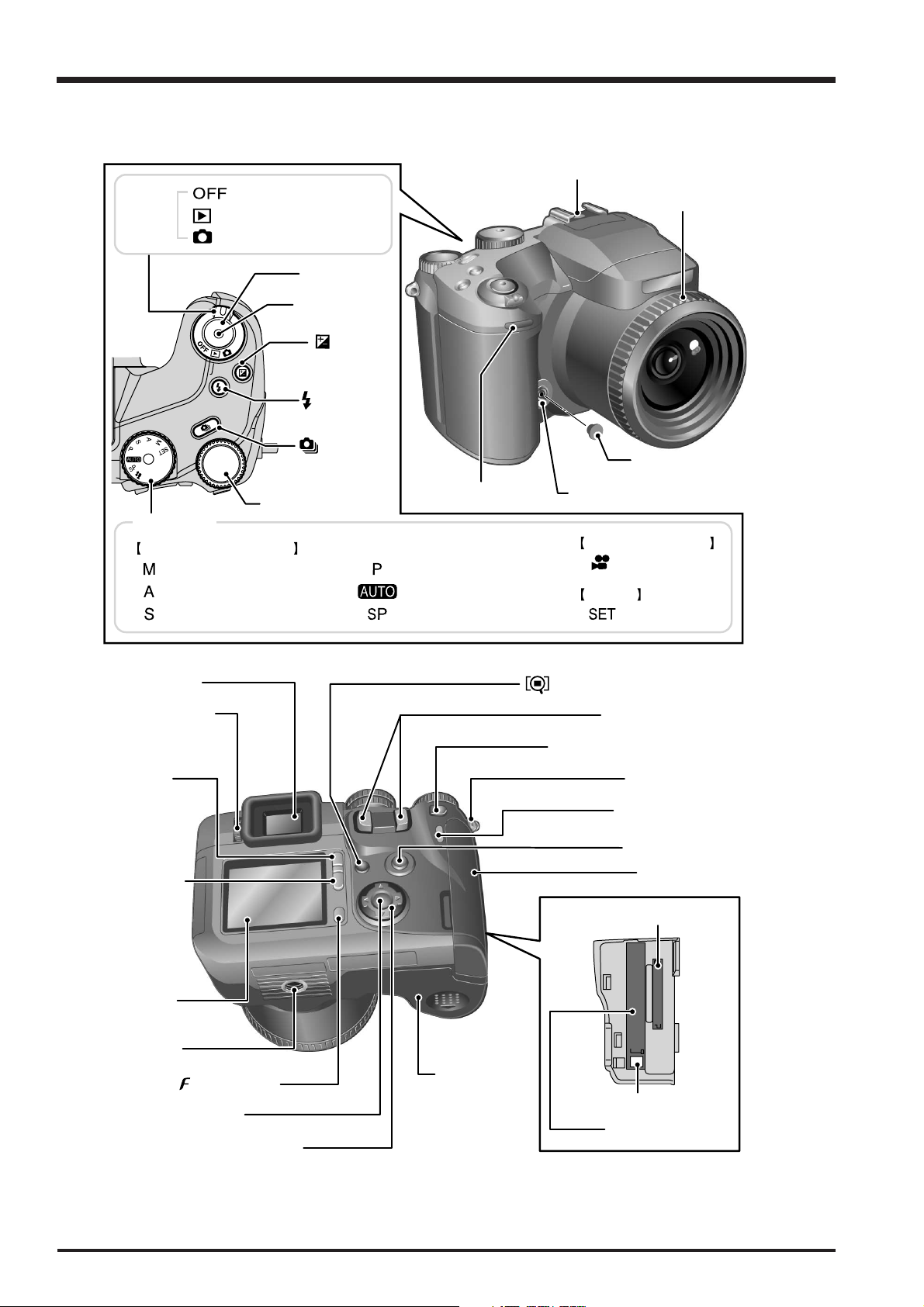
1. General
Command dial (P.20)
Continuous
shooting button
(P.50)
Exposure
compensation
button (P.53)
Flash button
(P.45)
Release socket
(P.25)
Shutter button
Power
switch
Playback mode (P.29)
Photography mode (P
.23)
Power-OFF
Mode dial
Set-up
Movie (P.67)
Programmed Auto (P
.41)Manual (P.44)
Set-up (P
.83)Shutter-priority Auto (P.42) Scene Position (P.40)
Aperture-priority Auto (P
.43)
Auto (P
.40)
Sync terminal (P.65)
Sync terminal cap
Hot shoe (P.64) FZ ring
(Focus/Zoom ring)
(P.21, 24, 48)
Self-timer lamp (P
.58)
Still image shooting
Movie recording
Strap mount (P.10)
Zoom button (P.19, 28)
AE-L (AE lock) button (P.21, 54)
BACK button (P.20)
Photo mode ( ) button (P.21)
DISP (display)
button
(P.21, 28)
Viewfinder (EVF)
Diopter adjustment
dial
(Focus check) button (P.21, 48)
Slot cover (P.14)
MENU/OK button (P.20)
4-direction (fg ) button (P.20)
Battery cover
(P.12)
LCD monitor
Indicator lamp (P.26)
EVF/LCD
(viewfinder/
monitor) button
(P.19, 23)
Tr
ipod mount
xD-Picture Card slot
(P.14)
Microdrive slot (P.14)
Microdrive eject button (P
.15)
1-2.Names of External Components
FinePix S20Pro Service Manual
8
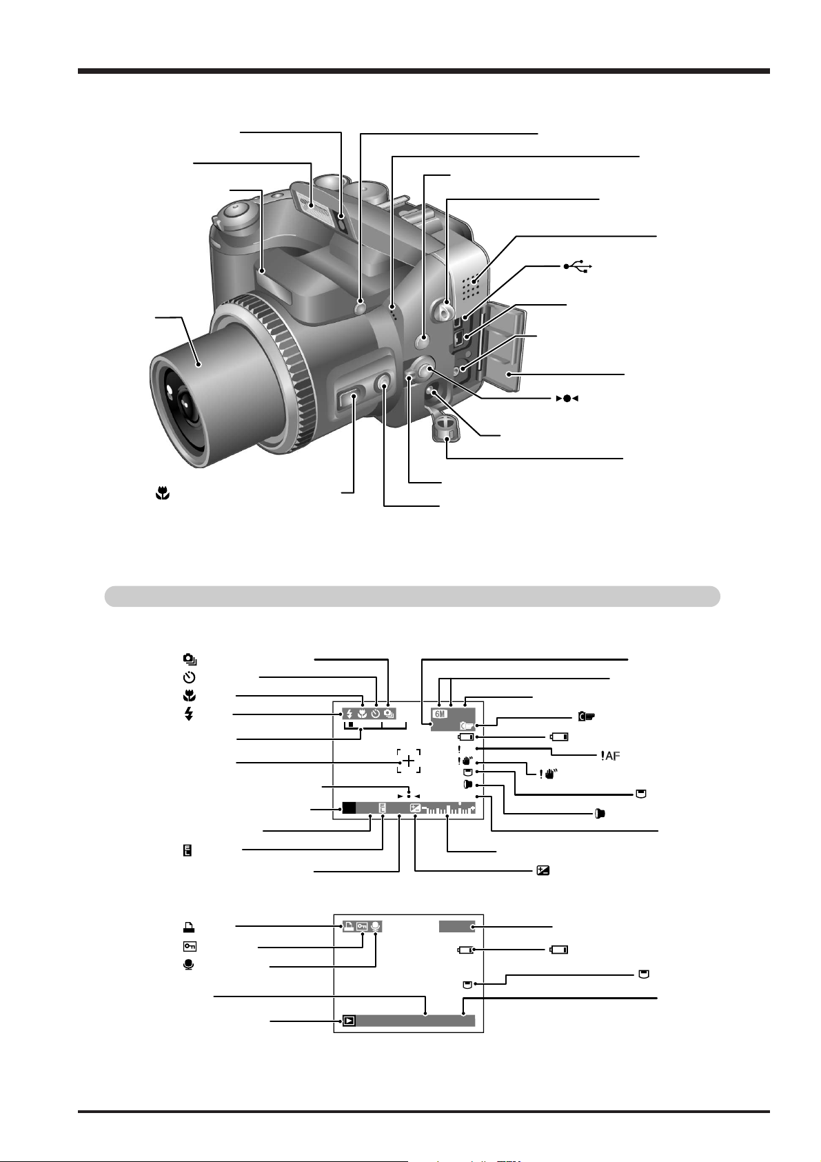
FinePix S20Pro Service Manual
Flash pop-up button (P.19, 45)
(One-touch AF) button
(P.21, 48)
SHIFT button (P.22)
Speaker
Microphone
A/V OUT (Audio/Visual output)
socket (P.98)
IEEE1394 socket (P.100)
DC IN 5V (power input) socket (P.98)
Terminal cover
Focus mode selector switch (P.21, 48)
Terminal cover
INFO (information check) button (P.21, 56, 70)
Strap mount (P.10)
USB socket (mini-B)
(P.100)
Lens
Macro (close-up photography)
button (P.21, 55)
Flash control sensor
Flash (P.45)
External AF
sensor
1. General
Example of screen text display
Still photography mode
Continuous shooting
Self-Timer
Macro
Flash
Zoom bar
AF frame
Focusing indicator marks
Still photography mode
Shutter speed
AE lock
Aperture setting display
Playback mode
DPOF
Protection
Voice memo
Date
Playback mode
Number of available frames
Exposure compensation indicator
Battery level warning
Camera shake warning
Exposure compensation
Playback frame number
Battery level warning
Sensitivity
Quality mode
FinePix COLOR
AF warning
Media
Adapter mode
Date
Media
Time
9
2. Disassembly
2. Disassembly
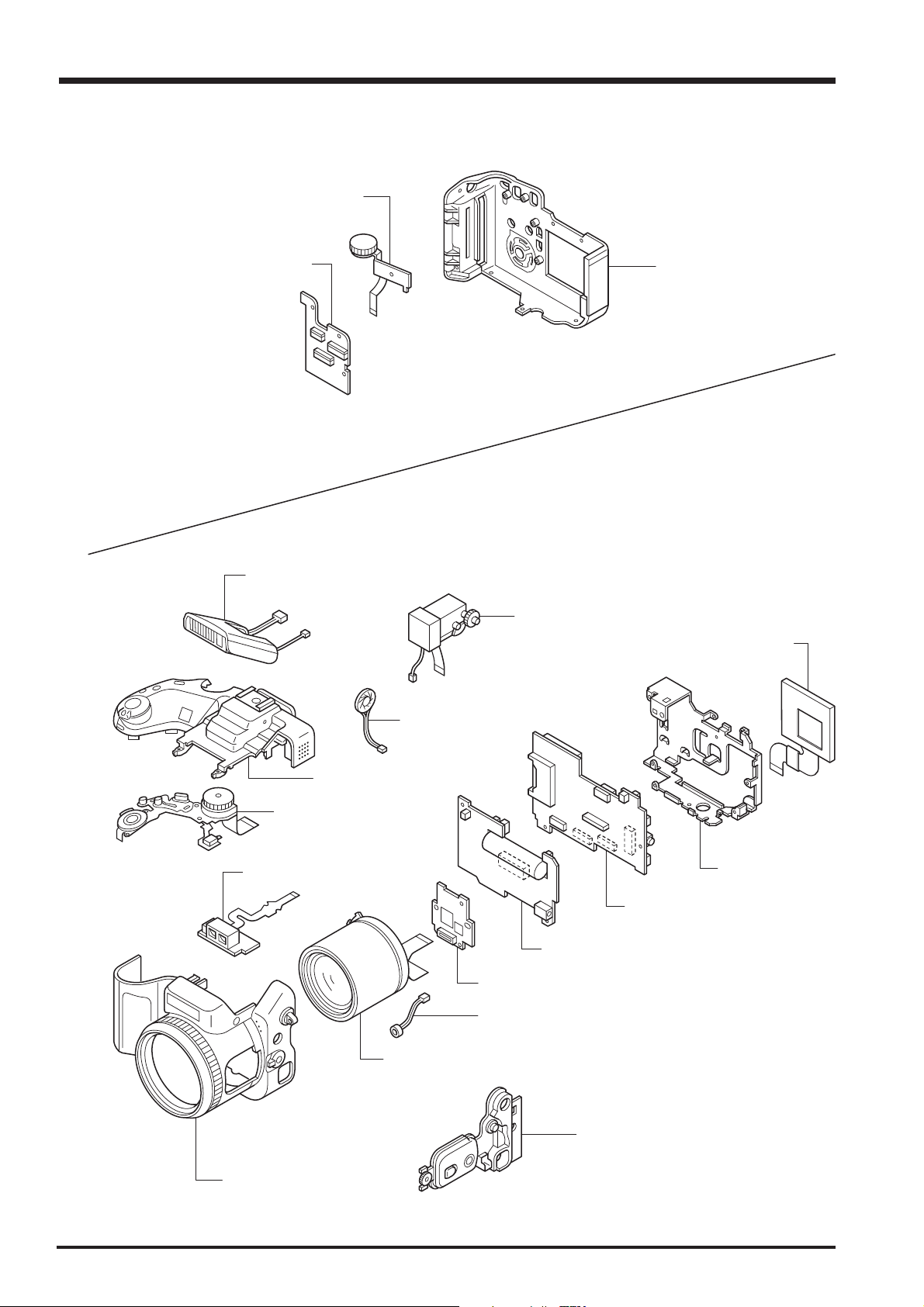
2-1. Names of Internal Components
C DIAL UNIT
FinePix S20Pro Service Manual
KEY PWB ASSY
ST ASSY CONST
R CABI ASSY
EVF CONST
LCD ASSY
TOP CABI ASSY
MODE DIAL UNIT
AF SENSOR UNIT
SPEAKER ASSY
LCD FRAME
MAIN PWB ASSY
DCST PWB ASSY
CAM PWB ASSY
MIC ASSY
LENS CONST
SIDE MODULE UNIT
10
F CABI ASSY

FinePix S20Pro Service Manual
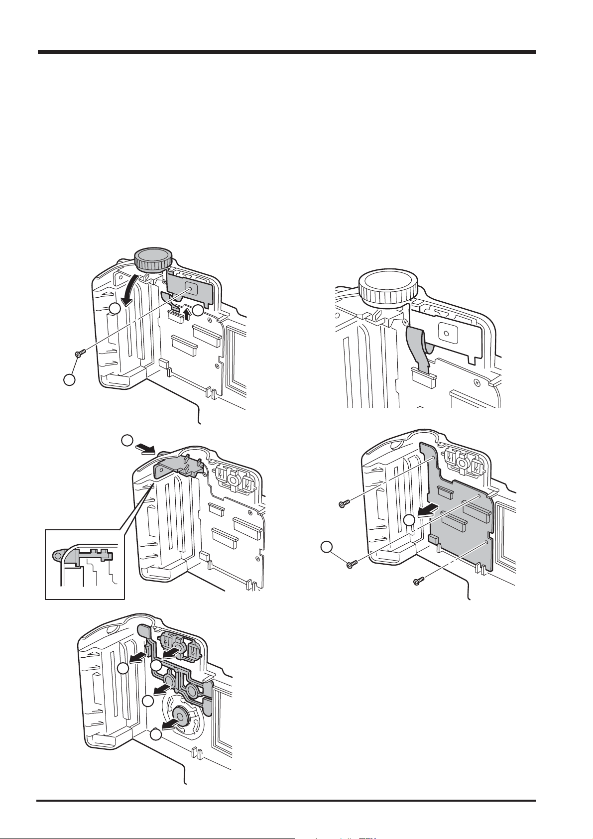
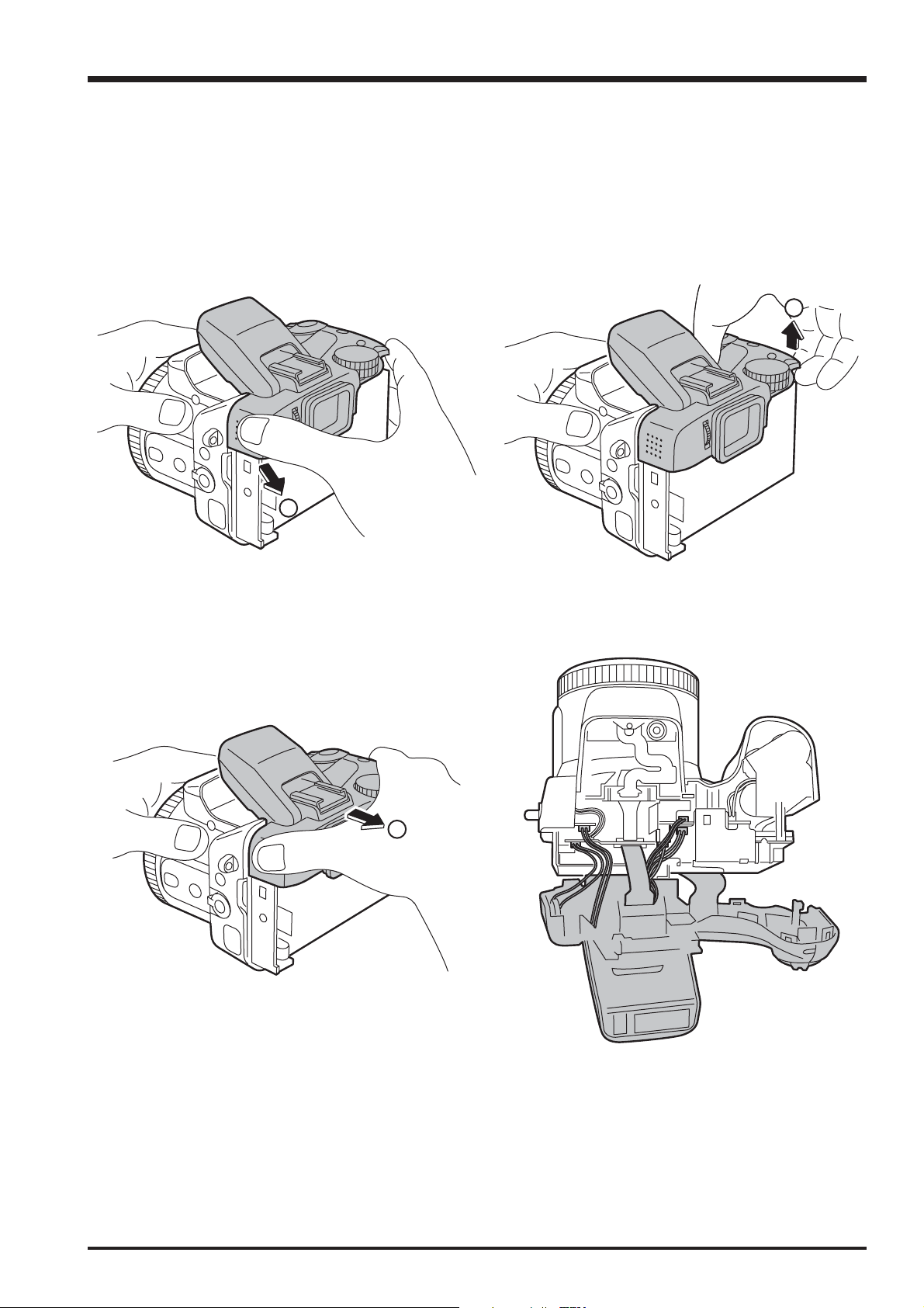
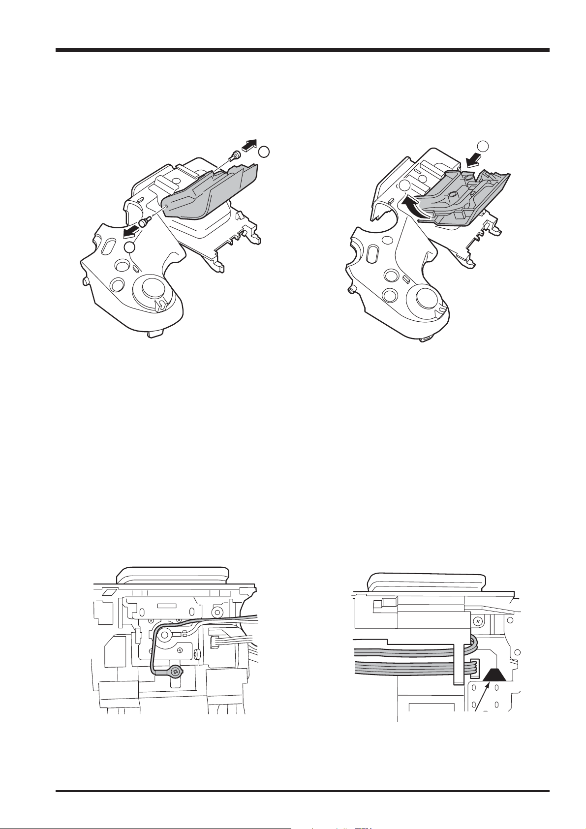
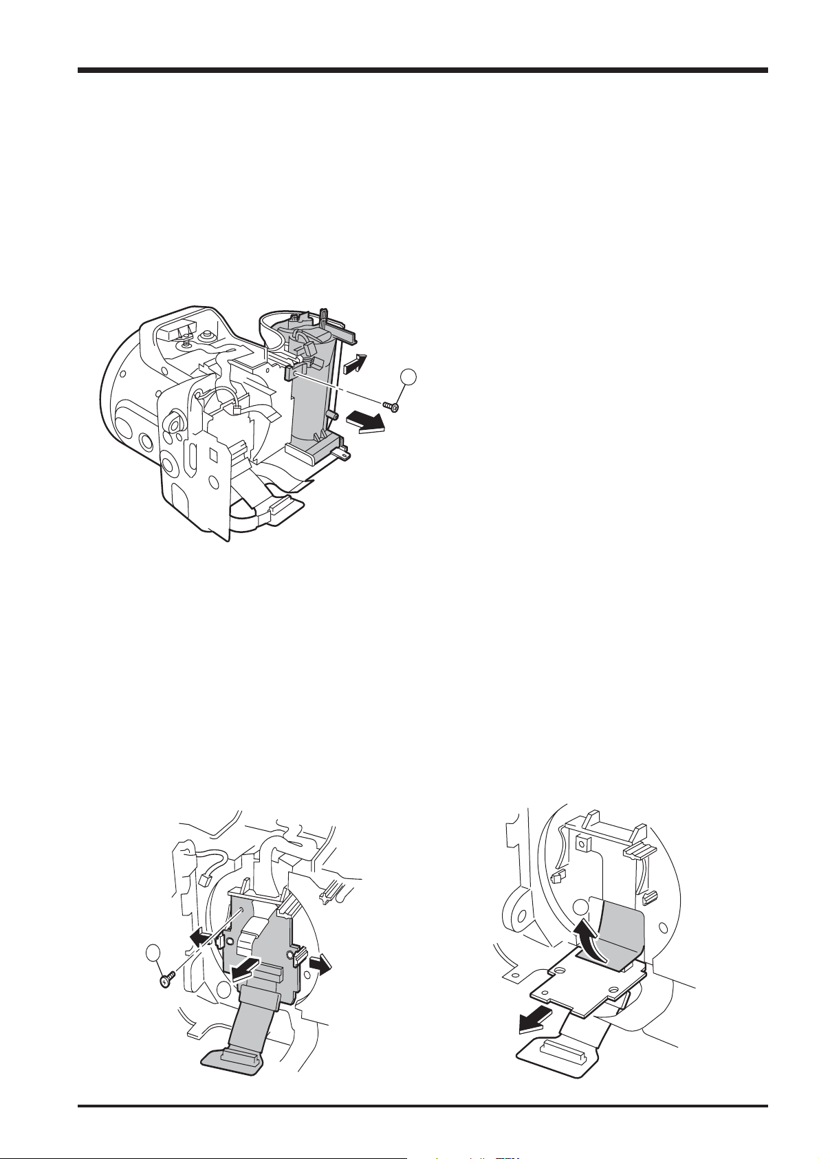
2-2. How to remove R CABI CONST
[Procedure]
1. Remove screw (M1.7x8.0).
2. Remove screw (M1.7x5.5).
3. Remove six screws (M1.7x5.0).
4. Remove R CABI CONST in the direction of the arrow.
5. Remove FFC(x2).
(The undermentioned refer to how to remove the connector. )
[Assembly procedure]
Assemble it according to a reverse procedure.
2. Disassembly
1
3
2
3
3
4
11
2. Disassembly
2-3. Decomposition of R CABI CONST
[Procedure]
1. Remove FFC from KEY PWB ASSY.
2. Remove screw (M1.7x4.0).
3. Remove C DIAL UNIT in the direction of the arrow.
4. Push STRAP L from the direction of the arrow and remove.
5. Remove three screws (M1.7x4.0).
6. Remove KEY PWB ASSY.
7. Remove OK BUTTON, REAR BUTTON, ZOOM BUTTOM, and LED LENS.
[Assembly procedure]
Assemble it according to a reverse procedure.
FinePix S20Pro Service Manual
3
2
4
1
6
5
12
7
7
7
7
FinePix S20Pro Service Manual
2. Disassembly
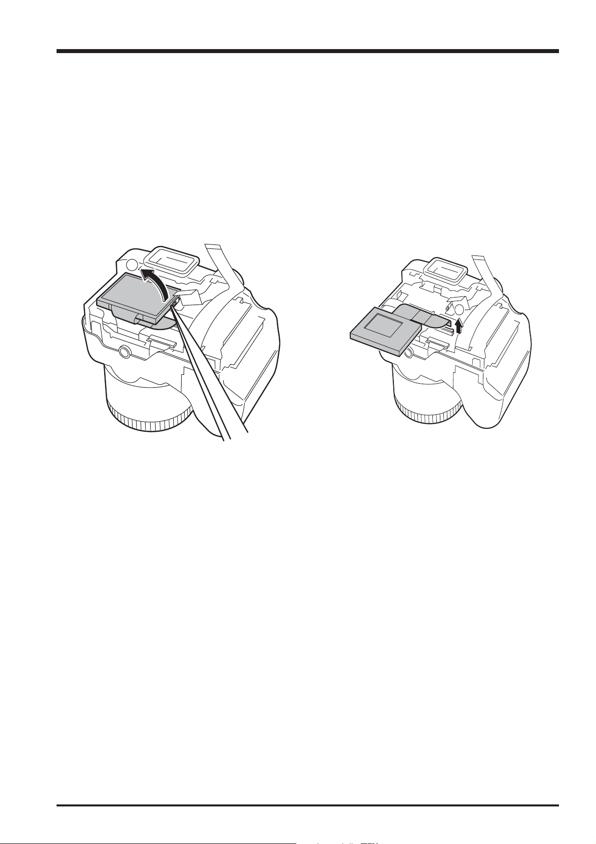
2-4. How to remove LCD ASSY
[Procedure]
1. Detach the undermentioned parts.
R CABI CONST
2. Put tweezers etc. in the LCD FRAME hook on LCD right side and remove LCD ASSY from LCD FRAME.
3. Remove the lock of the connector of MAIN PWB ASSY, and remove FFC from LCD ASSY.
2
3
[Assembly procedure]
Assemble it according to a reverse procedure.
13
2. Disassembly
FinePix S20Pro Service Manual
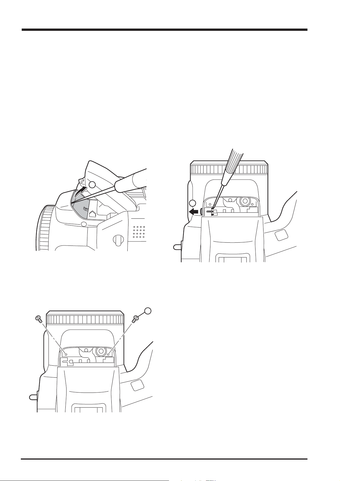
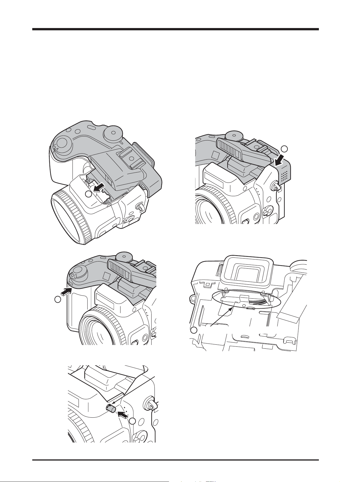
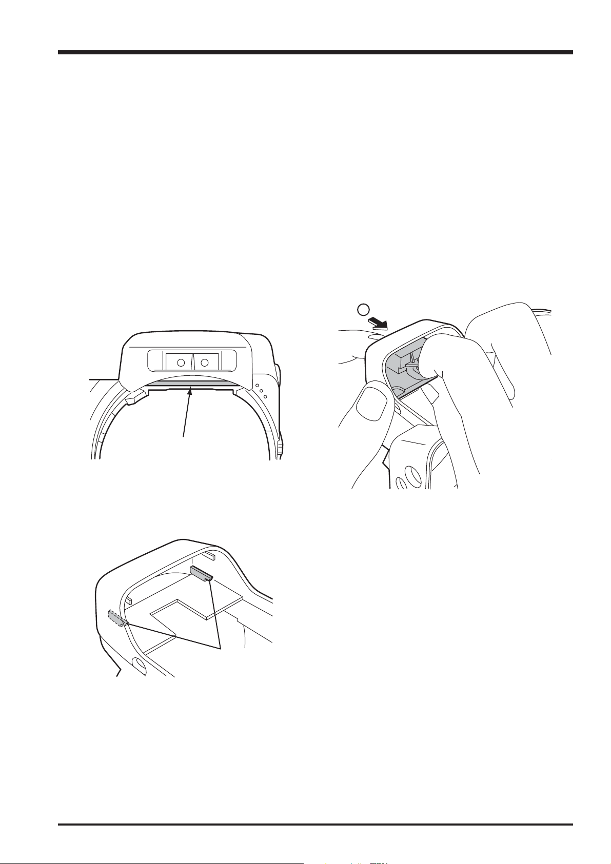
2-5. How to remove TOP CABI CONST
[Procedure]
1. Detach the undermentioned parts.
R CABI CONST, LCD ASSY
2. Push ST BUTTON, and improve the flash in pop.
3. Detach AF PLATE to the space between AF PLATE and F CABI CONST with a needle etc.
Note that neither AF PLATE nor F CABI CONST are damaged.
Do not stab the finger etc. enough when you use the needle.
4. Remove the hook of ST BUTTON and remove ST BUTTON from the main body by using a minus driver.
Do not lose because CSP(ST BUTTON) comes off together when ST BUTTON is detached.
5. Remove two screws (M1.7x5.5).
3
4
5
14
FinePix S20Pro Service Manual
6. Remove the speaker side of TOP CABI CONST in the direction of the arrow.
7. Lift the SHUTTER BUTTON side of TOP CABI CONST in the direction of the arrow and remove.
8. Remove from the main body while pulling TOP CABI CONST backward.
6
2. Disassembly
7
8
15
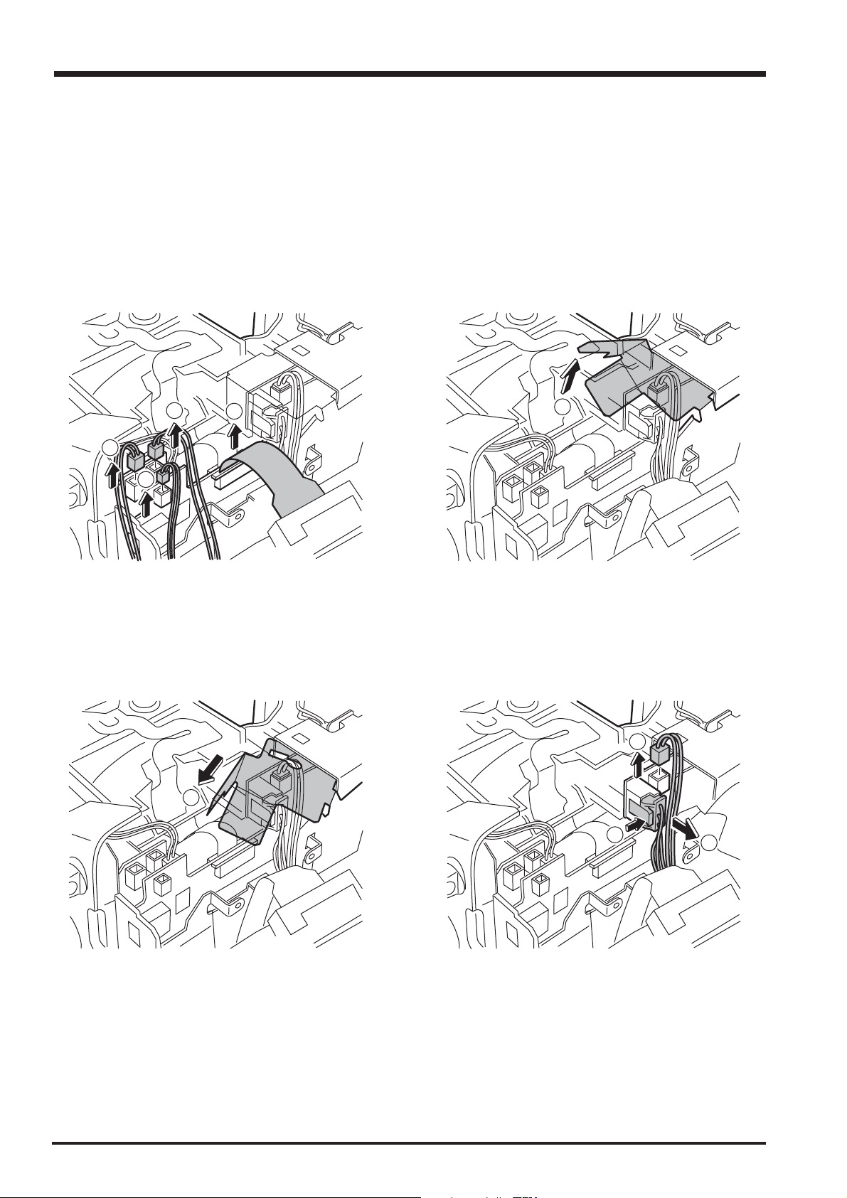
2. Disassembly
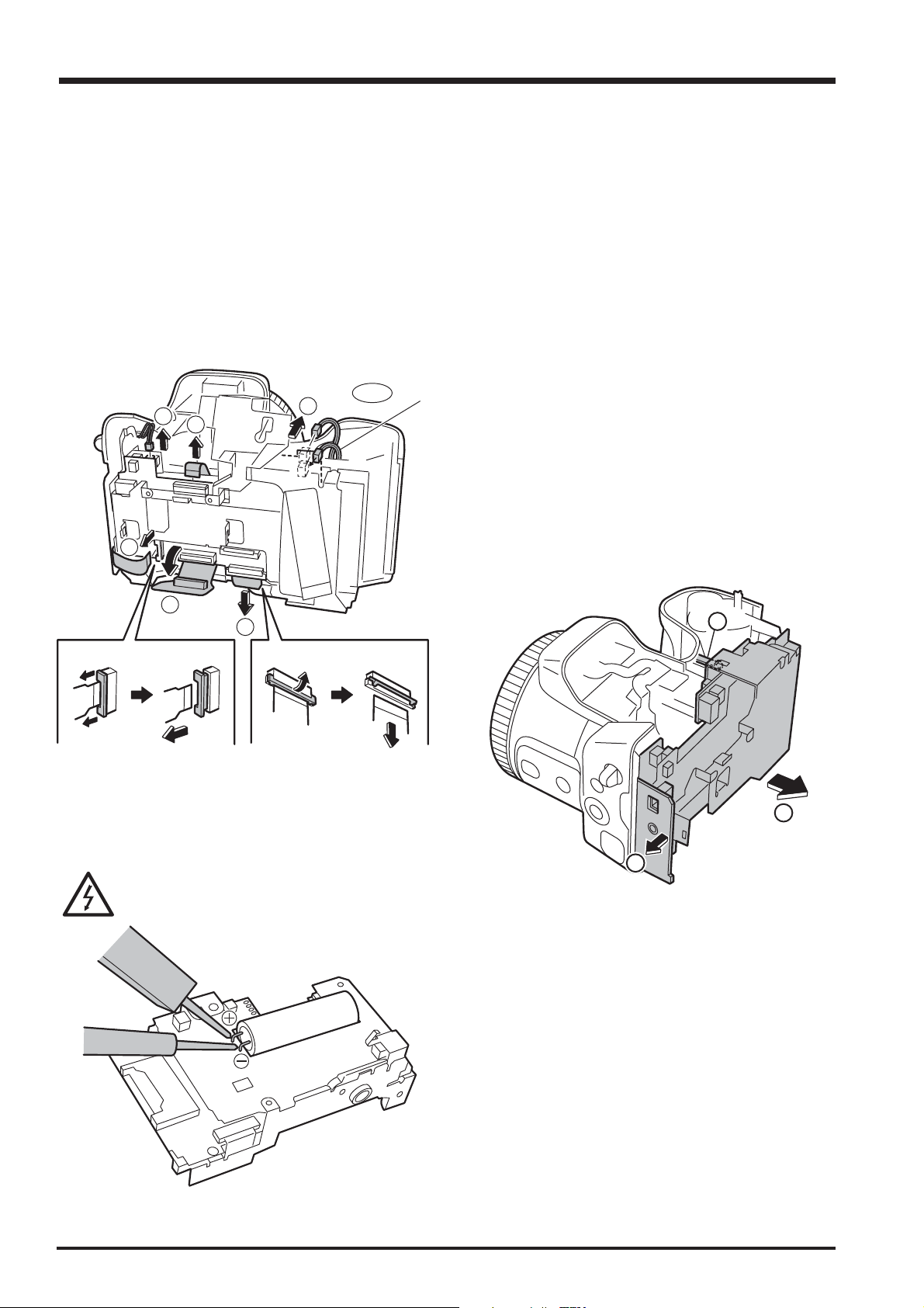
9. Remove Wire Harness (3) from TOP CABI CONST and FFC (1).
10. Pull out SHEET FRAME from LCD FRAME.
11. Remove Wire Harness (2).
There is no dread of the electric shock and do not touch the terminal when you remove Wire Harness
for the flash from the substrate.
FinePix S20Pro Service Manual
9
9
9
10
9
10
11
16
11
11
FinePix S20Pro Service Manual
2. Disassembly
[Assembly procedure]
Assemble it according to a reverse procedure.
1. Combine intuition on the tip of the AF sensor when you connect all Wire Harness with FFC.
2. Combine the speaker side of TOP CABI CONST in intuition in the hook of F CABI CONST.
3. Combine the grip part in intuition surely. At this time, confirm grip rubber is turned over and not transformed.
4. Confirm TOP CABI CONST and confirm Wire Harness has been installed after it clings surely in SHEET FRAME.
5. Note that it is at the top and bottom (The gate is the above) in ST BUTTON at assembly.
2
1
3
4
Note the scissors crowding of Wire Harness.
Gate position
5
17
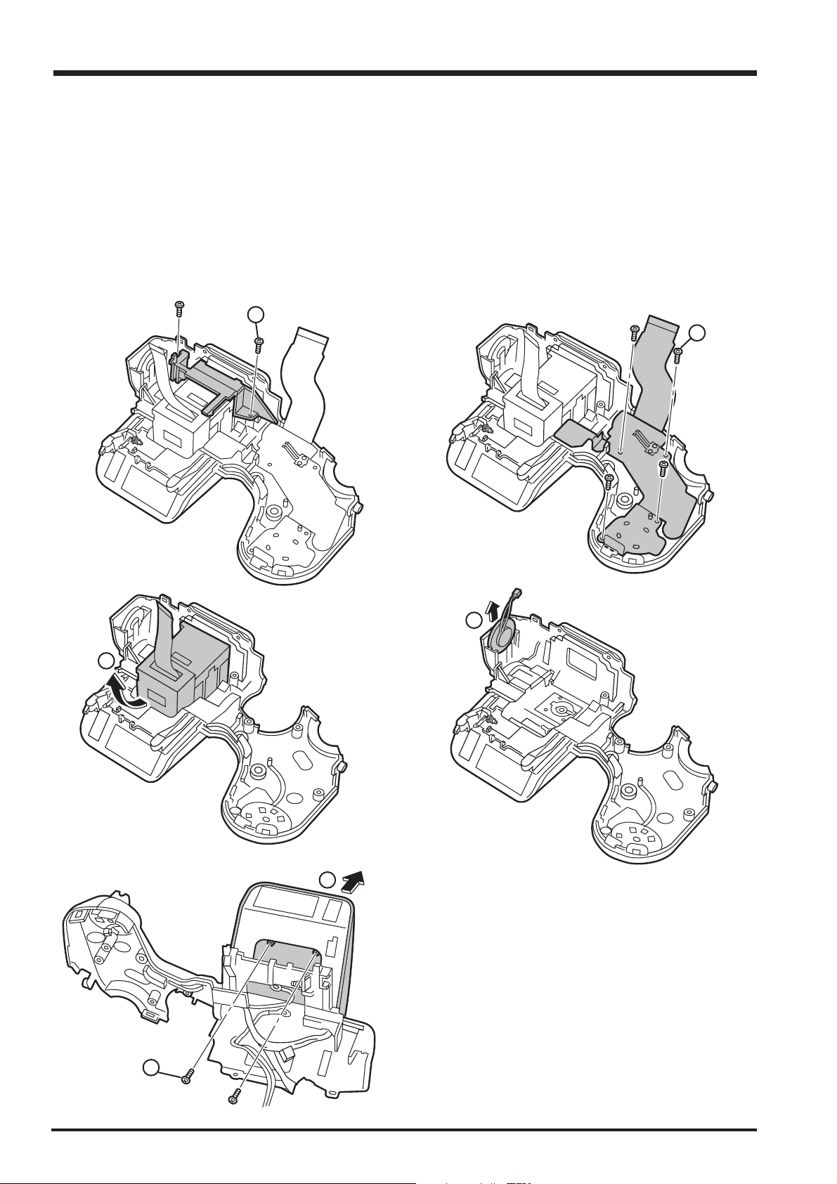
2. Disassembly
2-6. Decomposition of TOP CABI CONST
[Procedure]
1. Remove two screws (M1.7x4.0), and remove HOLDER EVF.
2. Remove four screws (M1.7x4.0), and remove MODE DIAL UNIT.
3. Remove EVF CONST.
4. Remove SPEAKER ASSY.
5. Remove two screws (M1.7x4.0), and remove ST TOP.
1
FinePix S20Pro Service Manual
2
4
3
5
18
5
FinePix S20Pro Service Manual
6. Remove ST SHUFT(x2).
7. Lift while pressing ST ASSY CONST against the SHUTTER BUTTON side and remove.
2. Disassembly
6
7
6
7
[Assembly procedure]
Assemble it according to a reverse procedure.
[Notes of assembly]
Note the taking turning of the flash hiss harness.
Pass the flash hiss harness and the flash harness through the fingernail of HOLDER EVF.
Do not float on the flash hiss harness and the flash harness.
<harness> do not interfere in flash pop up detection SW.
Flash pop up detection SW
19
2. Disassembly
2-7. How to remove LCD FRAME CONST
[Procedure]
1. Detach the undermentioned parts.
R CABI CONST, LCD ASSY, ST PLATE, ST BUTTON, TOP CABI CONST
2. Remove FFC Wire Haness (4)(2)(2-1).
3. Remove main body A and part B, and remove LCD FRAME CONST.
4. Discharge electricity from the main capacitor of DCST PWB ASSY.
[Assembly procedure]
Assemble it according to a reverse procedure.
2-1
2
2
2
SYNCHRO
FinePix S20Pro Service Manual
2
2
2
A
B
3
20
FinePix S20Pro Service Manual
2. Disassembly
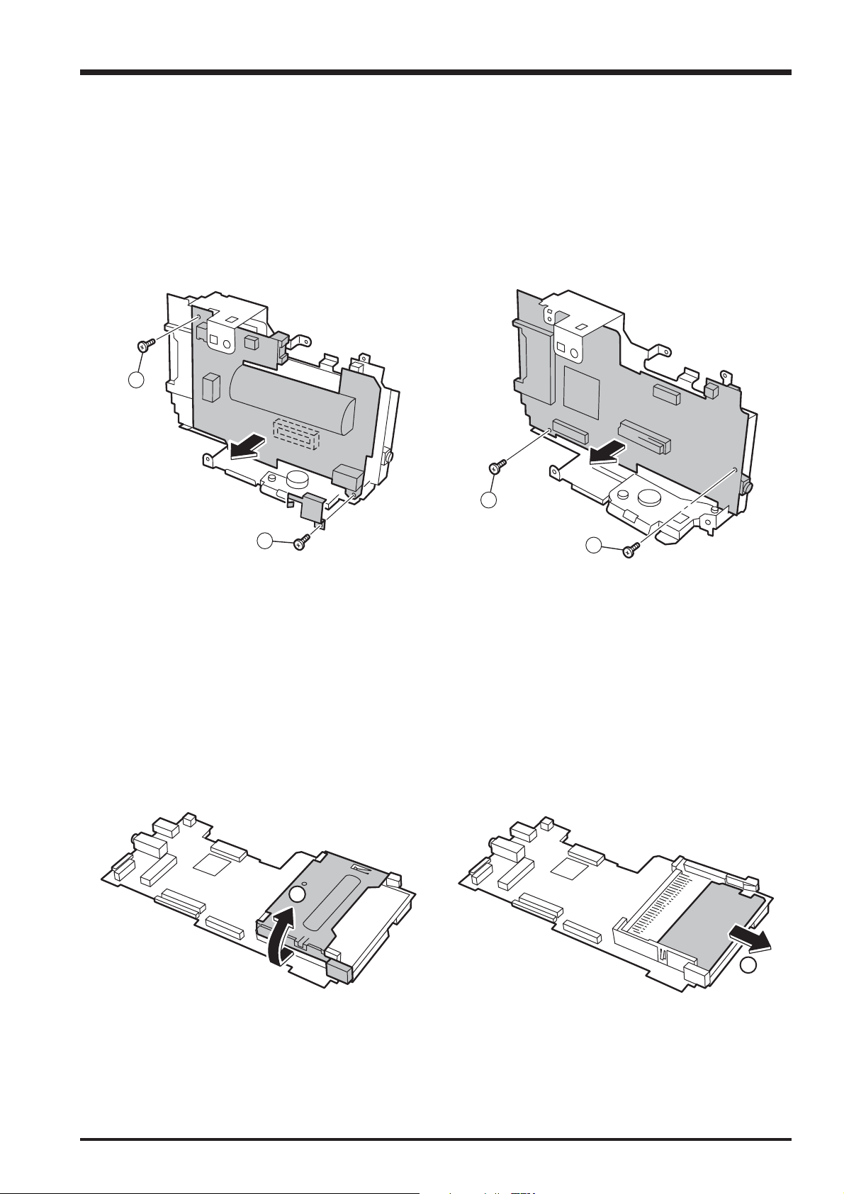
2-8. Decomposition of LCD FRAME CONST
[Procedure]
Confirm the main capacitor of DCST PWB ASSY has been discharged without fail before work is started.
1. Remove two screws (M1.7x3.0), and remove CONTACT PLT and DCST PWB ASSY.
2. Remove two screws (M1.7x3.0), and remove MAIN PWB ASSY.
[Assembly procedure]
Assemble it according to a reverse procedure.
1
1
2-9. Decomposition of MAIN PWB ASY
[Procedure]
1. Remove EJECTER in the direction of the arrow.
2. Remove SHEET CF.
[Assembly procedure]
Assemble it according to a reverse procedure.
1
2
2
2
21
2. Disassembly
FinePix S20Pro Service Manual
2-10. How to remove SHEET FRAME
[Procedure]
1. Remove SHEET FRAME from LCD FRAME.
[Assembly procedure]
Assemble it according to a reverse procedure.
[Notes of assembly]
Note the damage of SHEET FRAME when you install SHEET FRAME in LCD FRAME.
2-11. How to remove BATTERY LID
[Procedure]
1. Lift the hook of BATTERY LID, and remove BATTERY LID.
[Assembly procedure]
Assemble it according to a reverse procedure.
22
2
FinePix S20Pro Service Manual
2. Disassembly
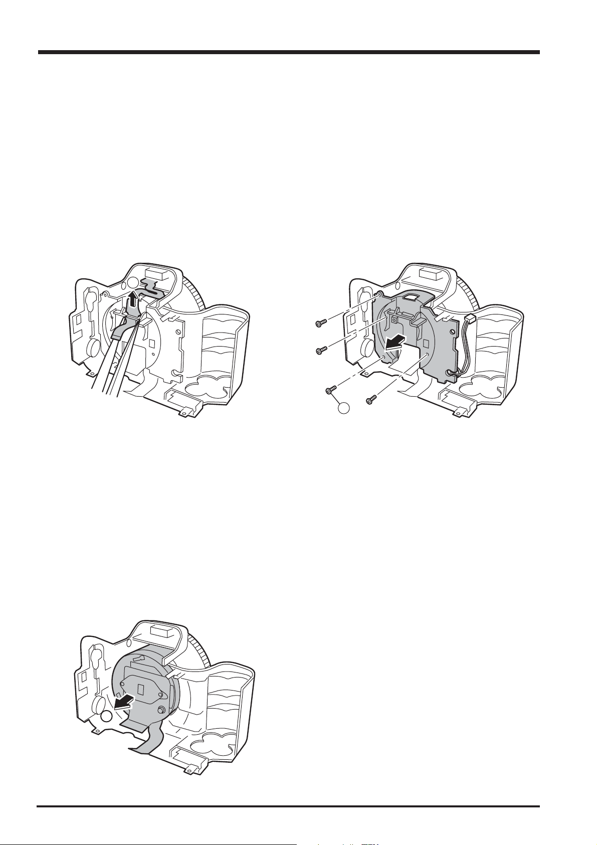
2-12. How to remove BATTERY HOLDER UNIT
[Procedure]
1. Detach the undermentioned parts.
R CABI CONST, LCD ASSY, ST PLATE, ST BUTTON, TOP CABI CONST, LCD FRAME CONST
BATTERY LID
2. Remove screw (M1.7x5.0).
3. Remove BATTERY HOLDER UNIT from the main body while opening the main body grip part.
[Assembly procedure]
Assemble it according to a reverse procedure.
2
2-13. How to remove CAM PWB ASSY
[Procedure]
1. Detach the undermentioned parts.
R CABI CONST, LCD ASSY, ST PLATE, ST BUTTON, TOP CABI CONST, LCD FRAME CONST
2. Remove screw (M1.7x5.0).
3. Open the hook of LENS FRAME, and remove CAM PWB ASSY in the direction of the arrow.
4. Remove FPC from LENS CONST, and remove CAM PWB ASSY from the main body.
[Assembly procedure]
Assemble it according to a reverse procedure.
4
2
3
23
2. Disassembly
FinePix S20Pro Service Manual
2-14. How to remove LENS FRAME
[Procedure]
1. Detach the undermentioned parts.
R CABI CONST, LCD ASSY, ST PLATE, ST BUTTON, TOP CABI CONST, LCD FRAME CONST
BATTERY LID, BATTERY HOLDER UNIT, CAM PWB ASSY
2. Remove FFC from LENS FRAME.
3. Remove screw (M1.7x5.0), and remove LENS FRAME from the main body.
[Assembly procedure]
Assemble it according to a reverse procedure.
[Notes of assembly]
Do so as not to cut FFC adding impossible power when you build FFC into LENS FRAME noting it.
2
3
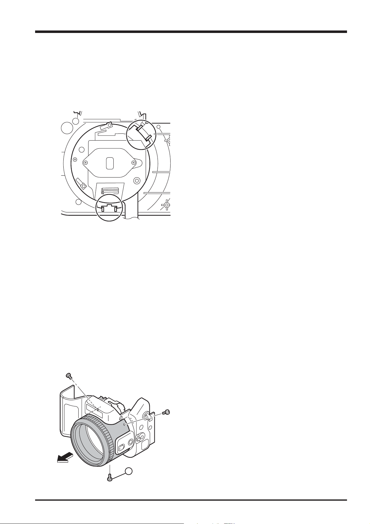
2-15. How to remove LENS CONST
[Procedure]
1. Detach the undermentioned parts.
R CABI CONST, LCD ASSY, ST PLATE, ST BUTTON, TOP CABI CONST, LCD FRAME CONST
BATTERY LID, BATTERY HOLDER UNIT, CAM PWB ASSY, LENS FRAME
2. Remove LENS CONST from F CABI UNIT.
24
2
FinePix S20Pro Service Manual
2. Disassembly
[Assembly procedure]
Assemble it according to a reverse procedure.
[Notes of assembly]
Make the cutting lack of the rib and LENS CONST of F CABI CONST combined in intuition,
and build it in when you build in LENS CONST.
2-16. How to remove LENS CABI ASSY
[Procedure]
1. Detach the undermentioned parts.
R CABI CONST, LCD ASSY, ST PLATE, ST BUTTON, TOP CABI CONST, LCD FRAME CONST
BATTERY LID, BATTERY HOLDER UNIT, CAM PWB ASSY, LENS FRAME, LENS CONST
2. Remove three screws (M1.7X3.5), and remove LENS CABI ASSY.
[Assembly procedure]
Assemble it according to a reverse procedure.
[Attention]
Because the torque is managed as for FOCUS RING of LENS CABI ASSY, it is not possible to decompose.
2
25
2. Disassembly
FinePix S20Pro Service Manual
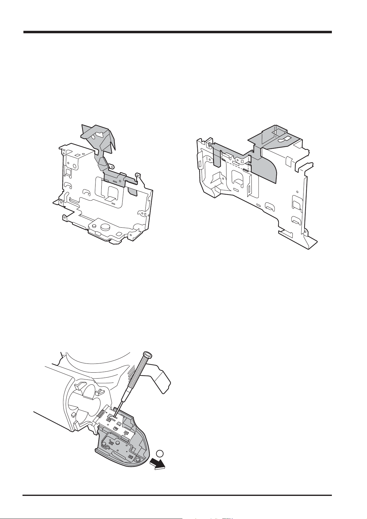
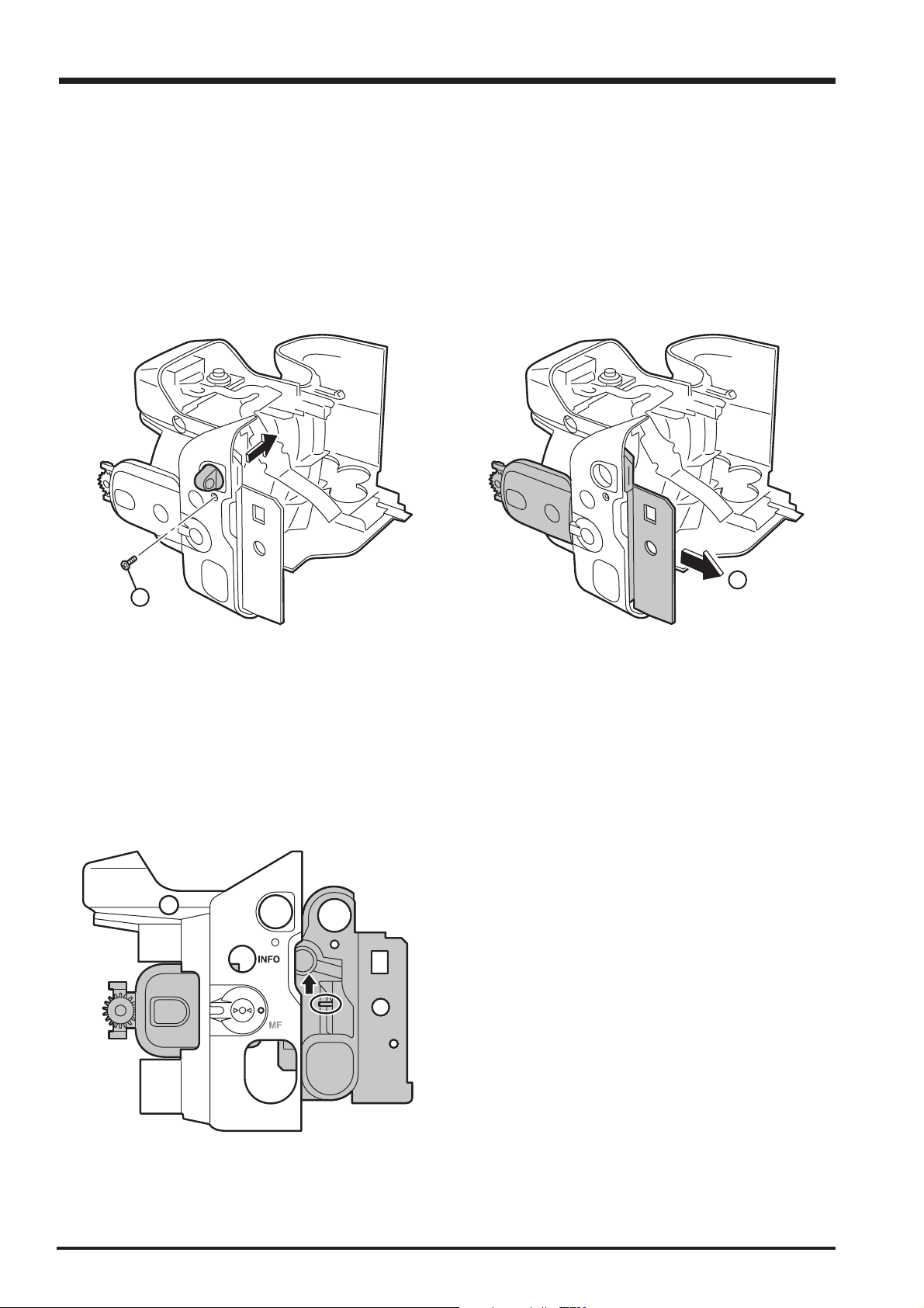
2-17. How to remove SIDE MODULE UNIT
[Procedure]
1. Detach the undermentioned parts.
R CABI CONST, LCD ASSY, ST PLATE, ST BUTTON, TOP CABI CONST, LCD FRAME CONST
BATTERY LID, BATTERY HOLDER UNIT, CAM PWB ASSY, LENS FRAME, LENS CONST
LENS CABI ASSY
2. Remove screw (M1.7x5.0), and remove STRAP R.
3. Remove SIDE MODILE UNIT from F CABI ASSY.
2
[Assembly procedure]
Assemble it according to a reverse procedure.
[Notes of assembly]
Match and build in the position of the FOCUS switch lever of FOCUS switch SW and F CABI ASSY
of SIDE MODILE UNIT.
C-AF
S-AF
3
26
FinePix S20Pro Service Manual
2. Disassembly
2-18. How to remove AF SENSOR UNIT
[Procedure]
1. Detach the undermentioned parts.
R CABI CONST, LCD ASSY, ST PLATE, ST BUTTON, TOP CABI CONST, LCD FRAME CONST
BATTERY LID, BATTERY HOLDER UNIT, CAM PWB ASSY, LENS FRAME, LENS CONST
LENS CABI ASSY
2. Remove AF SENSOR UNIT in the direction of the arrow while pushing the front side part of AF SENSOR UNIT by
the finger.
[Assembly procedure]
Assemble it according to a reverse procedure.
[Attention]
Replace F CABI ASSY when guide ditch part F CABI ASSY is damaged when AF SENSOR UNIT is detached.
2
AF SENSOR UNIT
Guide ditch part
27

3. Schematics
FinePix S20Pro Service Manual
3. Schematics
3-1. Cautions
<Cautions when replacing parts>
• Do not reuse removed parts. Always use new parts.
• Note that the -ve side of tantalum condensers is readily damaged by heat.
• Except for chemical condensers and tantalum condensers, voltage is not displayed on condensers with a
voltage resistance of 50V or less.
• Resistors not marked are 1/16W chip resistors.
• KW = 1000Ω, MW = 1000KΩ
• B characteristics of variable resistors and semi-fixed resistors are not displayed.
3-2. Basic Block Names and Functions
Part name Block name Function
LENS CONST CCD BLOCK CCD output
MAIN PWB ASSY CAMERA BLOCK CCD output A/D conversion (IC102)
CCD driver ( IC101,IC103)
PROCESS BLOCK Image signal processing, USB communications,
system control (IC210)
LCD/EVF BLOCK LCD/EVF output control. (IC850)
AUDIO BLOCK Audio IN/OUT(IC400)
DCST PWB ASSY DC/DC BLOCK Power supply generation (IC500)
POWER ON BLOCK Power supply management ,Key function(IC300)
FLASH BLOCK Flash charging control (IC601)
MOTOR BLOCK Shutter/iris/AF/zoom drive (IC353)
RSW PWB ASSY RSW BLOCK Power SW,Shutter SW
KSW PWB ASSY KEY SWICH BLOCK Key SW
MSW PWB ASSY MODE SWICH BLOCK Mode SW
FLASH UNIT FLASH BLOCK Flash
28

FinePix S20Pro Service Manual
3. Schematics
3-3.Functions of Primary Blocks
3-3-1.Technical Outline
Fujifilm's proprietary 6.2 megapixel (S-pixel: 3.1 million, R-pixel: 3.1 million) Super CCD SR (Super Dynamic Range)
sensor technology for near-film quality pictures with 2,832 x 2,128 (6.03 million) recorded pixels and dramatically
increased dynamic range.
Link strobes or other external flash systems to the FinePix S20 Pro through its PC-Sync port.
Take your pick, the FinePix S20 Pro offers two of the fastest image transfer protocols: IEEE 1394 (FireWire) and USB 2.0.
Movie photography performance is improved. Horizontal/vertical pixel mixing*2 inside the CCD using a new data
transfer system is the first to provide 30 frames per second in VGA format at greater than 3 megapixels.
[High-speed Twin AF] uses both an external AF sensor (passive phase difference) and the CCD AF for higher-speed
autofocus.
The [Super Macro] feature allows photography of a subject at distances down to one centimeter.
The [Double Slot] feature provides for both xD media and microdrives, allowing both recording of the large volumes
of image data in the high image quality mode, and long movies.
*1 : Image data obtained with honeycomb signal processing from twice the number of effective pixels. Shrinks four
pixels into one. This processing increases the signal level (sensitivity) by a factor of four, and the S/N ratio (signal-to-
noise ratio) by a factor of two, to permit photography at ISO1600.
*2 : Mixes two pixels on the vertical axis, and two pixels on the horizontal axis, of the CCD.
This processing increases the signal level by a factor of four, and the S/N ratio by a factor of two, to provide high
sensitivity and high quality images, while at the same time allowing data to be read at high-speed (30 frames per
second in VGA format).
3-3-2.CAM Board Block Functions
Photography Circuit Functions (CAM BLOCK)
The analog video signal output from the newly developed CCD is processed (pseudo-color compensation, adaptive
interpolation, amplification, and signal mixing) in ACS_IC (IC102:CSP_IC), and subsequently converted to a 12-bit
digital signal. The digital signal is then sent to the single chip image signal processing LSI : UCS2_IC (IC210 :
CSP_IC*).
* CSP_IC=
Chip Size Packege IC
3-3-3.MAIN Board Block Functions
Image Signal Processing Functions (PROCESS BLOCK)
Data input from CCD
* The 12-bit digital image data (1H equivalent) output from the CAM BLOCK is sent to UCS2_IC, buffered in the IBUF,
and converted to 32-bit (16-bit x 2) data. The 32-bit image data is then sent from the [I/O Buffer] in UCS2_IC and
stored in the SDRAM_IC (IC208, IC209 : 40 Mbyte). A single frame (4080 pixels x 3040 lines) of image data is tempo-
rarily stored in the SDRAM_IC.
* At the same time, AE multiplies the 12-bit image data input from the UCS2_IC in [AUTO], and sends the data required
for AE/AWB/AF to the SDRAM_IC. To provide the appropriate data for AE/AWB/AF, this data is then sent from the
SDRAM_IC in serial format to the ACS_IC via the UCS2_IC.
Recording in the xD media
The image data stored in the SDRAM_IC is converted from 32-bit to 12-bit data one line at a time in the [IBUF] in the
UCS2_IC, and sent to [YC PRO]. The image data is then converted to 8-bit Y and C signals in [YC PRO], and then sent
again to [IBUF]. The 8-bit Y and C signals are then converted to 8-bit Y, Y, Cb, and Cr signals and sent to the SDRAM_IC.
The image data stored in the SDRAM_IC is compressed with [JPEG] in the UCS2_IC and again stored in the
SDRAM_IC. The image data following compression is recorded sequentially in the xD media in the UCS2_IC.
Image Replay from the xD media
The compressed image data from the xD media is sent to UCS2_IC, and stored in the SDRAM_IC via [MEDIA]. The
compressed image data stored in the SDRAM_IC is expanded with JPEG and stored again in the SDRAM_IC. The
expanded image data is sent to [YC PRO] via [IBUF]. Gain control for the luminance and color difference signals, and
aperture processing, are performed in [YC PRO] and the image data then sent again to the SDRAM_IC. The image
data is then displayed via [ENCD] and [D/A].
Movie Mode
The 12 bit digital image data output from the (CAM BLOCK) is converted to 8-bit Y and C signals in the USC2_IC [YC
PRO], and sent to the SDRAM_IC. The image data stored in the SDRAM_IC is compressed with [JPEG] in the
UCS2_IC and again stored in the SDRAM_IC. The image data following compression is recorded sequentially in the
SSFDC via [MEDIA] in the UCS2_IC.
The photography adjustment data is stored in the FLASH_ROM (In the IC210). The FLASH_ROM also incorporates
firmware.
LCD Control Functions (LCD CONTROL BLOCK)
The R, G, and B signals processed in the image signal processing UCS2_IC are output to the LCD panel via [LCD CONT].
A low-temperature polysilicon TFT color LCD monitor (1.8, 118,000 pixels) is used.
EVF Control Functions (EVF CONTROL BLOCK)
The R, G, and B signals processed in the image signal processing UCS2_IC are output to the EVF panel via [EVF CONT].
A high-temperature polysilicon TFT color monitor (0.44, 235,000 pixels) is used in the viewfinder.
3-3-4.DCST Board Block Functions
Power Supply Functions
The power supply circuit on the DCST board generates the -8V/-11V/16V (CCD), 1.5V (UCS2_IC), 3.3V
(ACS_IC/UCS2_IC/SDRAM/SDRAM/ROM/LED/KEY), MOT_5.0V (lens/flash), D_5V (AUDO), LCD_13V (LCD/EVF
backlight), D_3.3V (LCD circuit), and AD_3.3V (video circuit) voltages.
29
3. Schematics
(
)
(
)
(
)
(
)
(
)
_
_
(
)
A
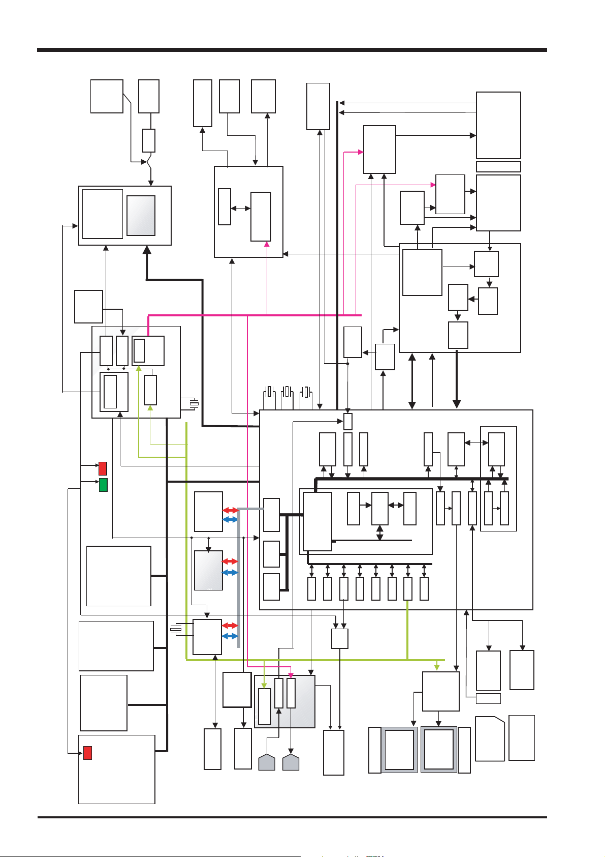
3-4. Block Diagram
CCD16V,-8V
LCD8.5V
Etc.
PWCTL,3.3V_ON
Backup
BATT
BATT.
AAx4
5V
CCD_ON,
3.3V
1.5V
5V
FUSE
AN30211A
DC/DC IC.
7ch
DC IN
DC/DC Block
HOT Shoe
P-TR
STRB-C
STRB_DIS,STRB_FULL,STRB_COK
UPC5023GR
STRB CONT
STRB-XE
STRB BLOCK
STRB IC
G_NO,G_SEL,
STRB_CHG
STRB_SY
AF Sensor
IST,GS1,GS2,END,S/S,CP
FinePix S20Pro Service Manual
M50233HP
Motor Drv.
6ch
VI_CONT,VF_CONT,VZ_CONT
SHT PULSE
OFD_CONT
Focus,Iris,Zoom Pulse
MD2174
V Pulse
MODULE
V Drv.
(Programble)
TG
Pulses
OFD/RG
BIAS
Gain
Cont.
V
H
Digital
Zoom HP
Zoom position
Focus HP
14bit
6xZOOM LENS
IRIS 13Steps WIDE/TELE Variable
O.LPF
HA-CCD-SR
1/1.7inch
3.1M. pixels x 2
CCDIN
CDS
ACS AD80057AKBC_36
3.3V Operation
ADC
LED_R, LED_G
LED_ST
VIDE
O_ON
RTC
PIO
Power on
Reset
RESET
LED
LED
EVF/LCD SW
F Mode SW
PinP SW
AEL SW
MACRO SW
FOCUS SW
SHIFT SW
OPAF SW
INFO SW
COMMAND
COMMAND DIAL
TELE/WIDE SW
MODULE
EVR
SIO
8ch
CTL
(U2_SIO)
PWON
(EVR_SIO
SIO_1
SIO_2
_ACT
)
OK/BACK/DISP SW
R/L/D/U SW
KEY
C-AF/S-AF/MF SW
MODULE
SIDE
PWON IC
FF1166
X’TAL
CX-101F 24.00MHz
32.768kHz
256Mb x16
SDRAM
X2
(IN UCS2)
FLASH
4MB
M66591GP
UBS2.0
Cont
,STRB_CC
IEEE1394
Cont
X’TAL CX-101F
24.375MHz
I/O Buffer I/O Buffer
Internal
eDRAMA
Internal
eDRAMA
Internal
eDRAMB
Internal
eDRAMB
SIO_1
(U2_SIO)
MIC
AMP
CTL
X’TAL CX-101F
24.545MHz
48.000MHz
SP
BH6415KN
AMP
X’TAL CX-101F
Detect system
JPEG JPEG
BUS Cont.
BUS Cont.
SDRAMC
SDRAMC
DMAC
DMAC
PORTPORT
CLKCCLKC
Driver
BEEP
AUDIO IC
UDIO_OUT
36MHz
1/4 Dividing
frequency
36.00Mhz
A/D
Audio
Audio
Audio
Audio
Seriul
Seriul
A/D
A/D
I-cache 16kI-cache 16k
CPU CoreCPU Core
Peripheral BUS 96MHz Peripheral BUS 96MHz
DAC
Video
ICUICU
VBS_OUT
MFTMFT
OSC
CAM_ON
USB
SIO_1
(U2_SIO)
VI,HI,ADCK,STB,
LD,DI,WAIT,RW
VRESET,OCONT
CGENCGEN
TX49 CPU Core TX49 CPU Core
DEBUG I/FDEBUG I/F
ENCDENCD
WDT
SIOSIO
SIO_1
(U2_SIO)
CXM4006R.
Cont
Code
Gray
CCD[13-0]
YCPRO YCPRO
TFDCTFDC
EVF/LCD
MEDIAMEDIA
20PIN
DR_SW
CCDIFCCDIF
Slot
xD Card
IBFC
RECC RECC
AUTOAUTO
UCS2
LIBRA 3.3V Operation
( S I P )
CF Card
50PIN
Slot
IC702
MODE MODULE
RELEASE SW(S1/S2)
STROBE
+/-
DRIVE SW
POWER/CAM/PB SW
MODE DIAL
LED
POPUP SW
SELF TIMER
30
USB Jack
IEEE Jack
MIC
SPEAKER
AV Jack
BL LED x3
LCD Panel
1.8inch
0.44inch
EVF
EVF BL
xD PictureCard
Micro Drive
 Loading...