

Page 1
DIGITAL CAMERA
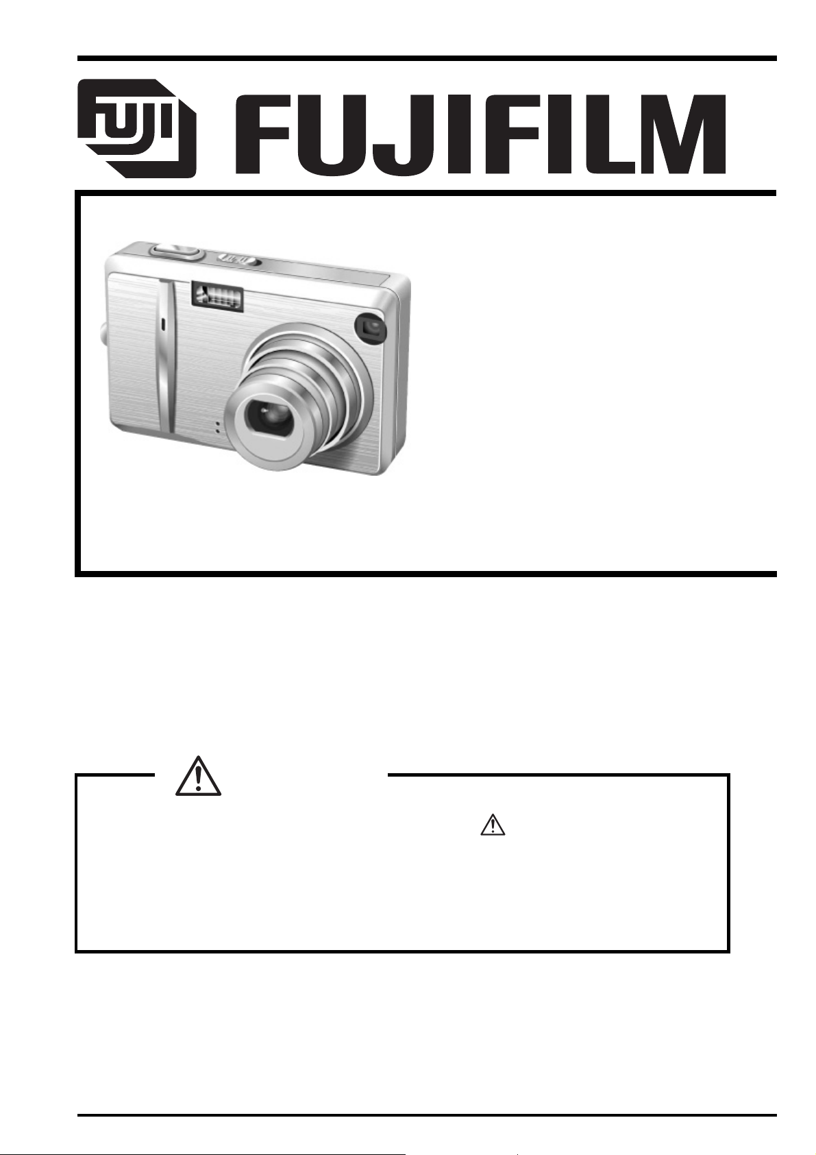
FinePix F455
TROUBLESHOOTING GUIDE
US/CA/EU/EG/GE/AS-Model
z THE COMPONENTS IDENTIFIED WITH THE MARK “
DIAGRAM AND IN THE PARTS LIST ARE CRITICAL FOR SAFETY.
PLEASE REPLACE ONLY WITH THE COMPONENTS SPECIFIED ON THE SCHEMATIC
DIAGRAM AND IN THE PARTS LIST.
WARNING
” ON THE SCHEMATIC
z IF YOU USE PARTS NOT SPECIFIED, IT MAY RESULT IN A FIRE AND AN
ELECTRICAL SHOCK.
Ref.No.: ZM00579-400
FUJI PHOTO FILM CO., LTD.
Printed in Japan 2005. 06
Page 2
FinePix F455 TROUBLESHOOTING GUIDE
SAFETY CHECK-OUT
After correcting the original problem, perform the following
safety check before return the product to the customer.
1. Check the area of your repair for unsoldered or
poorly soldered connections. Check the entire
board surface for solder splasher and bridges.
2. Check the interboard wiring to ensure that no
wires are “pinched” or contact high-wattage
resistors.
3. Look for unauthorized replacement parts,
particularly transistors, that were installed during
a previous repair. Point them out to the customer
and recommend their replacement.
4. Look for parts which, though functioning, show
obvious signs of deterioration. Point them out to
the customer and recommend their replacement.
5. Check the B + voltage to see it is at the values
specified.
6. Make leakage - current measurements to
determine that exposed parts are acceptably
insulated from the supply circuit before returning
the product to the customer.
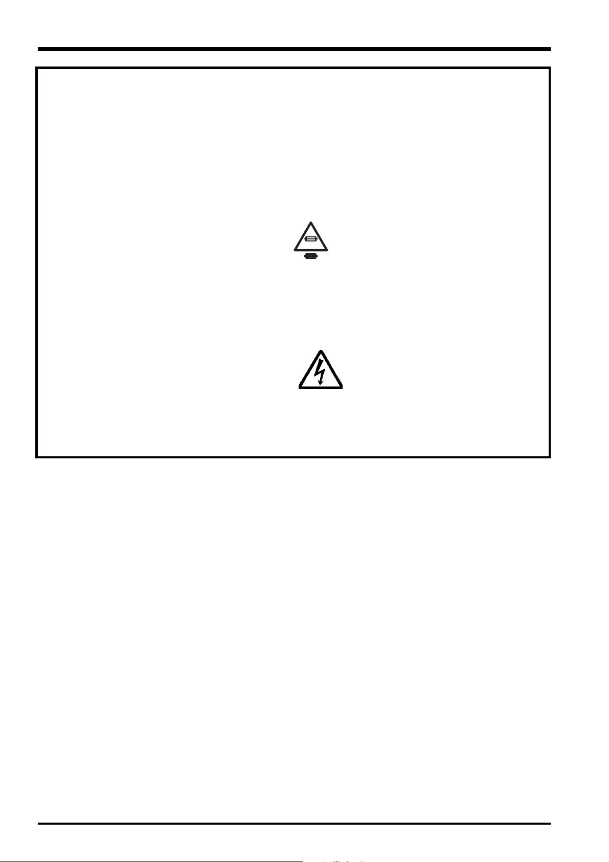
7.
2.5A 125V
2.5A 125V
8.
RISK OF FIREREPLACE FUSE
AS MARKED
WARNING!
HIGH VOLTAGE
CAUTION: FOR CONTINUED
PROTECTION AGAINST FIRE
HAZARD, REPLACE ONLY
WITH SAME TYPE 2.5
AMPERES 125V FUSE.
ATTENTION: AFIN
D'ASSURER UNE
PROTECTION PERMANENTE
CONTRE LES RISQUES
D'INCENDIE, REMPLACER
UNIQUEMENT PAR UN
FUSIBLE DE MEME, TYPE 2.5
AMPERES, 125 VOLTS.
WARNING:
TO REDUCE THE ELECTRIC
SHOCK, BE CAREFUL TO
TOUCH THE PARTS.
2
Page 3

FinePix F455 TROUBLESHOOTING GUIDE
TABLE CONTENTS
1. Power .........................................................................................................................4
1-1. Power cuts out in mid-operation.................................................................................................4
2. LCD.............................................................................................................................5
2-1. LCD monitor does not show images .......................................................................................... 5
2-2. LCD monitor does not show images .......................................................................................... 5
2-3. LCD monitor cracked ................................................................................................................. 5
3. Lens............................................................................................................................6
3-1. Zoom error displayed .................................................................................................................6
3-2. Camera stops working after the lens extends ............................................................................ 6
3-3. Lens barrier fails to open............................................................................................................7
3-4. Lens barrier fails to open............................................................................................................7
4. Operation ...................................................................................................................8
4-1. The mode does not change .......................................................................................................8
4-2. The mode does not change .......................................................................................................8
4-3. The mode does not change .......................................................................................................9
4-4. None of the control buttons on the back of the camera work.....................................................9
5. Other ........................................................................................................................10
5-1. Card error displayed................................................................................................................. 10
5-2. The flash makes a sputtering noise when it fires ..................................................................... 10
5-3. The cradle remains in USB mode and will not switch to PLAY ................................................ 11
3
Page 4

FinePix F455 TROUBLESHOOTING GUIDE
1. Power
1-1. Power cuts out in mid-operation.
Fault details: In both Camera mode and Playback mode, the camera sometimes emitted a short beep
and then turned off. Pressing lightly on the battery cover caused this to happen.
Analysis results: Vibration or stress applied to the camera body caused the battery cover detection switch
(SW401) to malfunction and turn the camera off.
Repair details:
The solution was to fit a replacement DCST PWB ASSY with modifications to the SW401 and its surrounding
circuits, or to replace the individual parts (See Bulletin GS-2005-022).
4
Page 5

FinePix F455 TROUBLESHOOTING GUIDE
2. LCD
2-1. LCD monitor does not show images
Fault details: The LCD monitor display was abnormal. The display was white and no images appeared.
Analysis results: The LCD flexible cable was pushed onto connector CN501 but was not locked in place.
We simply locked the cable in place and confirmed that images were displayed correctly.
Repair details:
Relocked connector CN501.
2-2. LCD monitor does not show images
Fault details: LCD monitor does not show images. No image appears.
Analysis results: Rectified by replacing the LCD CONST.
Repair details:
Replace the LCD CONST.
2-3. LCD monitor cracked
Fault details: The LCD monitor was cracked.
Analysis results: A crack ran up from the lower-left corner of the LCD. The corresponding section of the R
panel showed impact marks and a depression towards the LCD panel, indicating that the
damage was caused by external impact or pressure.
Repair details:
Replace the LCD CONST.
5
Page 6

FinePix F455 TROUBLESHOOTING GUIDE
3. Lens
3-1. Zoom error displayed
Fault details: A zoom error was displayed. The lens was distorted or dislodged.
Analysis results: The lens was damaged and bent. This appeared to be lens damage caused by an impact
while the lens was extended.
Repair details:
Replace the LCD CONST
3-2. Camera stops working after the lens extends
Fault details: When the camera was turned on in photography mode, it stopped working after the lens
extended. The camera also would not turn off.
Analysis results: Replacing the DCST PWB restored normal camera operation. We observed large amounts
of solder scrap spattered around DCST PWB D411, L404 and C406 (mostly on the CCD6V power supply circuit) with some short-circuiting.
Repair details:
Replace the DCST PWB
6
Page 7

FinePix F455 TROUBLESHOOTING GUIDE
3-3. Lens barrier fails to open
Fault details: Lens barrier fails to open.
Analysis results: There was a thin film on the upper and lower blades of the lens barrier that caused the
blades to catch.
Repair details:
Replace the LENS CONST.
3-4. Lens barrier fails to open
Fault details: Lens barrier fails to open.
Analysis results: Fine dust had got into the barrier mechanism. Large amounts of the same type of dust
were also observed on the lens surface, indicating that the dust adhered to the lens
while the camera was being used.
Repair details:
Replace the LENS CONST.
7
Page 8

FinePix F455 TROUBLESHOOTING GUIDE
4. Operation
4-1. The mode does not change
Fault details: The camera does not switch to still photography mode when still photography mode is
selected.
Analysis results: The mode could not be changed because the lever on KEY PWB SW801 was missing.
(SW801 remains fixed in the center position (open = Movie mode).
Repair details:
Replaced SW801 on the KEY PWB ASSY.
4-2. The mode does not change
Fault details: The camera does not switch to still photography mode when still photography mode is
selected.
Analysis results: Because the KEY PWB locking screw (SCREW_BT2M1.7 X 3.0) was not fitted, KEY PWB
SW801 was floating loose on the PWB so that the lever did not engage with the mode
button fitting (MODE PSP) and SW801 did not change.
Repair details:
Attached SCREW_BT2M1.7 X 3.0.
8
Page 9

FinePix F455 TROUBLESHOOTING GUIDE
4-3. The mode does not change
Fault details: The mode does not change.
Analysis results: The switch was unstable, since simply applying the tester to measure the voltage at pin 10
on CN201 for the mode signal line sometimes switched the camera to Movie mode. This
indicated a high impedance state such as a break in the same signal line in the KEY FPC.
Replacing the KEY PWB ASSY rectified the problem.
Repair details:
Replace the KEY PWB ASSY.
4-4. None of the control buttons on the back of the camera work
Fault details: None of the control buttons on the back of the camera work.
Analysis results: Connector CN201 on the MAIN PWB was broken and the KEY FPC was dislodged.
Breaks and peeling in the copper film on the LCD indicate that the damage is due to the
camera being disassembled by someone other than Fujifilm.
Repair details:
Replace the MAIN PWB ASSY.
9
Page 10

FinePix F455 TROUBLESHOOTING GUIDE
5. Other
5-1. Card error displayed
Fault details: Card error displayed.
Analysis results: When the media was inserted and the camera was turned on, a card error was displayed.
The solder on pin 18 (D7) in card socket CN401 on the DCST PWB ASSY was found to be
dislodged. We confirmed that the camera functioned normally after the pin was resoldered.
Presumably, imperfect soldering produced a false connection and after the camera was
shipped the connection was dislodged while the camera was being used.
Repair details:
Resoldered pin 18 (D7) in card socket CN401 on the DCST PWB ASSY.
5-2. The flash makes a sputtering noise when it fires
Fault details: The flash makes a sputtering noise when it fires.
Analysis results: The solder for the xenon tube in the flash was dislodged. This caused problems such as
discharging noises, sparking and vapor emissions under the strong current used when the
flash fired. Resoldering restored normal operation.
Repair details:
Resoldered the xenon tube in the flash.
10
Page 11

FinePix F455 TROUBLESHOOTING GUIDE
5-3. The cradle remains in USB mode and will not switch to PLAY
Fault details: The cradle remains in USB mode and will not switch to PLAY.
Analysis results: The mode could not be changed because the boss on the USB <=> PLAY switch (SW2)
was snapped off.
Repair details:
Replace the CRADLE.
11
Page 12

FUJI PHOTO FILM CO., LTD.
26-30, Nishiazabu 2-chome, Minato-ku, Tokyo 106-8620, Japan.
 Loading...