

FUJIFILM FinePix 4800 SERVICE GUIDE
DIGITAL CAMERA
FinePix4800Zoom
SERVICE GUIDE
U/E/EG_Model
WARNING
THE COMPONENTS INDENTIFIED BY THE MARK ON THE SCHEMATHIC DIAGRAM AND
IN THE PARTS LIST ARE CRITICAL FOR SAFETY.
PREASE REPLACE ONLY BY THE COMPORNENTS SPECIFIED ON THE SCHEMATHIC DIAGRAM
AND IN THE PARTS LIST.
IF YOU USE WITH PART NUMBER UN-SPECIFIED, IT MAY RESULT IN A FIRE AND AN
ELECTORICAL SHOCK.
FUJI PHOTO FILM CO.,LTD.
Printed in Japan 2001.05(T.S)
Ref.No.:ZM00363-100
SAFETY CHECK-OUT
After correcting the original problem, perform the following safety
check before return the product to the costomer.
FinePix4800Zoom(U/E/EG) SREVICE GUIDE
1. Check the area of your repair for unsoldered or
poorly soldered connections. Check the entire
board surface for solder splasher and bridges.
2. Check the interboard wiring to ensure that no
wires are “pinched” or contact high-wattage
resistors.
3. Look for unauthorized replacement parts,
particularly transistors, that were installed
during a previous repair. Point them out to the
customer and recommend their replacement.
4. Look for parts which, though functioning, show
obvious signs of deterioration. Point them out
to the customer and recommend their
replacement.
5. Check the B + voltage to see it is at the values
specified.
6. Make leakage - current measurements to
determine that exposed parts are acceptably
insulated from the supply circuit before returning
the product to the customer.
7. CAUTION: FOR CONTINUED
PROTECTION AGAINST FIRE
2.5A125V
2.5A125V
RISK OF FIREREPLACE FUSE
AS MARKED
HAZARD, REPLACE ONLY WITH
SAME TYPE 2.5 AMPERES 125V
FUSE.
ATTENTION: AFIN D'ASSURER
UNE PROTECTION PERMANENTE
CONTRE LES RISQUES
D'INCENDIE, REMPLACER
UNIQUEMENT PAR UN FUSIBLE
DE MEME, TYPE 2.5 AMPERES,
125 VOLTS.
8. WARNING:
WARNING!
HIGH VOLTAGE
TO REDUCE THE ELECTRIC
SHOCK, BE CAREFUL TO TOUCH
THE PARTS.
2

FinePix4800Zoom(U/E/EG) SERVICE GUIDE
TABLE OF CONTENTS
1. Specifications
1-1.Product Specifications ............................................................................................................................. 4
2. Names of Components
2-1.Names of External Components .............................................................................................................6
2-2.Names of internal Components .............................................................................................................. 7
3. Disassembly
3-1.Removing R PANEL ASSY, F PANEL ASSY ........................................................................................8
3-2.Removing MODE DIAL ASSY,B/W LCD,KEY PWB ASSY .................................................................. 9
3-3.Removing BARRIER MOTOR HEAD,LENS BARRIER ........................................................................ 9
3-4.Removing ST PWB UNIT,XE PWB UNIT ........................................................................................... 10
3-5.Removing LENS CONST ...................................................................................................................... 11
3-6.Removing DC PWB ASSY ................................................................................................................... 11
3-7.Removing MAIN PWB ASSY................................................................................................................ 12
3-8.Removing BATTERY CONNECTOR,PWB HOLDER ........................................................................ 12
TABLE OF CONTENTS
Page
4. Adjustment and Inspection
4-1.Important point Adjustment when Replacing Major Parts ................................................................ 13
4-2.Preparations for Adjustment ................................................................................................................ 13
4-2-1.Required Measuring Equipment ................................................................................................... 13
4-2-2.List of Jig Used ............................................................................................................................... 13
4-2-3.Measuring Intrument and Jig Connection Diagram .................................................................... 14
4-2-4.Setup for adjustment...................................................................................................................... 14
4-2-5.Various downloading software decompressions, preservation methods, and notes ............. 16
4-2-6.Install the DSC jig driver and the PC adjustment software ....................................................... 17
4-3.Adjustment Using the PC ..................................................................................................................... 18
4-3-1.Setting up the Adjustment Software............................................................................................. 18
4-3-2.FFWJ217.EXE Command Description ......................................................................................... 20
4-3-3.Writing and Reading From the EEPROM .................................................................................... 20
4-3-4.Starting the Adjustment Software ................................................................................................. 22
4-3-5.[ L ] : Display LCD Adjustment...................................................................................................... 23
4-3-6.[ C ] : CCD defect Data Write/OFD Adjustment .......................................................................... 23
4-3-7.[ M ] : Mode Dial/Battery Voltage Adjustment ............................................................................. 24
4-3-8.[ D ] : DC Jack Voltage Adjustment.............................................................................................. 24
4-3-9.[ P ] : Picture Adjustment .............................................................................................................. 25
4-3-10.[ A ] : AF Adjustment.................................................................................................................... 26
4-3-11.[ S ] : Flash Adjustment ............................................................................................................... 27
4-3-12.[ F1 ] , [ F2 ] : Display Adjustment Results ( 1 ), ( 2 ) .............................................................. 27
4-3-13.[ F ] : Firmware Download ........................................................................................................... 28
4-3-14.[ E ] : End Setting ......................................................................................................................... 29
4-4.Inspection ............................................................................................................................................... 31
4-4-1.Inspection and shipment setting................................................................................................... 31
4-5.Hexadecimal to decimal Conversion Table ........................................................................................ 31
5. List of Adjustment Addresses and Data
5-1.U model and E/EG model commonness............................................................................................. 32
5-2.Address name and data which E/EG model uses ............................................................................. 65
6. Appendix
6-1.List of Related Technical Updates Issued ......................................................................................... 66
3

1.Specifications
FinePix4800Zoom(U/E/EG) SERVICE GUIDE
1. Specifications
1-1. Product Specifications
System
Model Digital camera FinePix4800 ZOOM
Storage media SmartMedia (3.3V)
File format Still image: Exif ver.2.1 (JPEG)
Movie: AVI format, Motion JPEG
Audio: Exif Ver. 2.1 audio file standard-compliant
Image file size 2400 x 1800 pixels (4.32 million pixels)/1600 x 1200 pixels/1280 x 960 pixels/
640 x 480 pixels
Storage media SmartMedia (3.3V)
Number of frames recorded
Pixel 2400 x 1800 1600 x 1200 1280 x 960
640 x 480
Movie Audio
(Video) recording
Quality Mode FINE
Image Data Size
4MB (MG-4S) 2 4 11 4 9 6 12 44
8MB (MG-8S) 4 9 23 10 19 12 25 89
16MB (MG-16S/SW)
32MB (MG-32S/SW)
64MB (MG-64S/SW)
128MB (MG-128SW)
CCD sensor 1/1.7-inch Super CCD (with primary color filter)
Viewfinder Real image optical
Lens Super EBC Fujinon optical 3x zoom lens
Aperture F2.8/F7.0 (Wide-angle) to F4.5/F10.8 (Telephoto)
Focus TTL contrast-type, Auto or Manual
Focus distance f = 8.3 mm - 24.9 mm
Exposure control TTL 64-zones metering, Program AE, exposure compensation available in Manual
Sensitivity Equivalent to ISO 125/200/400
White balance Auto (In Manual modes, 7 positions can be selected.)
Focal range Normal: Approx. 60 cm (2.0 ft.) to infinity
Shutter Variable-speed, 3 sec. to 1/2000 sec. (using AE)
Flash Auto flash using flash control sensor
LCD monitor 2-inches, low-temperature polysilicon TFT 130,000 pixels
Video output NTSC (U.S.A./Canada model)/PAL (Europe model)
Self-Timer 10 sec. timer clock
Approx. Approx. Approx. Approx. Approx. Approx. Approx. Approx.
1700KB 803KB 328KB 762KB 590KB 620KB 320KB 90KB
NORMAL
8 194620392549163
18 38 94 41 79 50 99 330
36 77 189 82 159 101 198 663
74 156 379 166 319 204 398 1330
The total number of pixels: 2.47 million in an interwoven pattern.
The number of effective pixels: 2.306 million.
(Equivalent to 36 mm - 108 mm on a 35 mm camera)
photography mode
Macro: Approx. 20 cm (0.6 ft.) to 80 cm (2.6 ft.)
Effective range Wide-angle Approx. 0.6m - 3.5 m (2.0 ft. - 11.5 ft.)
Telephoto Approx. 0.6m - 2 m (2.0 ft. - 6.6 ft.)
Flash modes: Auto, Red-Eye Reduction, Forced Flash, Slow Synchro
BASIC FINE
NORMAL
FINE
NORMAL NORMAL
Approx. 191 sec.
Approx. 385 sec. Approx. 135 sec.
Approx. 774 sec. Approx. 272 sec.
--
--
Approx. 23 sec. Approx. 8 sec.
Approx. 47 sec. Approx. 16 sec.
Approx. 94 sec. Approx. 33 sec.
Approx. 67 sec.
4

FinePix4800Zoom(U/E/EG) SERVICE GUIDE
Input/Output Terminals
A/V Output Stereo mini- jack (1)
Digital USB (1) for image data output with a PC
DC Input Socket for specified AC power adapter
Cradle connection socket
For connection to supplied cradle
Power supply and Others
Power supply Use one of the following
*Rechargeable Battery NP-80 or AC Power Adapter AC-5V/AC-5VH
Available shots / time using the battery (When fully charged)
1.Specifications
Battery type No. of Shots Auto Play
NP-80
The number of shots shown here is an approximate guide to the number of consecutive shots that can be taken
based on 50% flash usage at normal temperatures. However, the actual number of available shots will vary depending on the ambient temperature when the camera is used and the amount of charge in the battery. The number
of available shots or available shooting time will be lower in cold conditions.
Conditions for use Temperature: 0 degree to +40 degrees
Camera dimensions 80 mm x 97.5 mm x 36.3 mm/3.1 in. x 3.8 in. x 1.4 in.
(W/H/D) (not including accessories and attachments)
Camera mass (weight) 258 g/9.1 oz.
Weight for photography Approx. 300 g/10.6 oz.
Cradle dimensions 80 mm x 53 mm x 80 mm/3.1 in. x 2.1 in. x 3.1 in.
(W x H x D)
Cradle mass weight Approx. 125 g/4.4 oz.
Cradle I/O terminals
Accessories SmartMedia (16MB, 3.3V) (1) NP-80 Rechargeable Battery (1)
Optional Accessories
LCD monitor ON Approx. 120 Approx.1 hour Approx.1 hour
LCD monitor OFF Approx. 250
(+32 degrees Fahrenheit to +104 degrees Fahrenheit)
80% humidity or less (no condensation)
(not including accessories, batteries or SmartMedia)
(including batteries and SmartMedia)
DC input socket, digital (USB) socket and connector socket (for camera connection)
Supplied with: Cradle (Picture Cradle) (1)
*Anti-static case (1) Hand strap (1)
*Index label (1) Owner's Manual (1)
AC Power Adapter AC-5V/AC-5VH (approx. 2 m (6.6 ft.) connection cord) (1)
A/V Cable (approx. 1.5 m (4.9 ft.), mini-plug (2.5 mm dia.) to pin-plug cable) (1)
Interface Set (1)
*CD-ROM (1)
*Special USB cable with Noise Suppression core (1)
*Software Quick Start Guide (1)
SmartMedia
MG-4S: 4MB, 3.3V MG-8S: 8MB, 3.3V MG-16S/SW: 16MB, 3.3V
MG-32S/SW: 32MB, 3.3V MG-64S/SW: 64MB, 3.3V MG-128SW: 128MB, 3.3V
AC Power Adapter AC-5V/AC-5VH BC-80 Battery Charger
NP-80 Rechargeable Battery PC-AD3 PC Card Adapter
Floppy Disk Adapter (FlashPath) SM-R2 Image Memory Card Reader
DM-R1 Image Memory Card Reader SC-FX8
-
* With fully charged battery
Audio Recording
Approx.3 hour
5
2.Names of Components
2. Names of Components
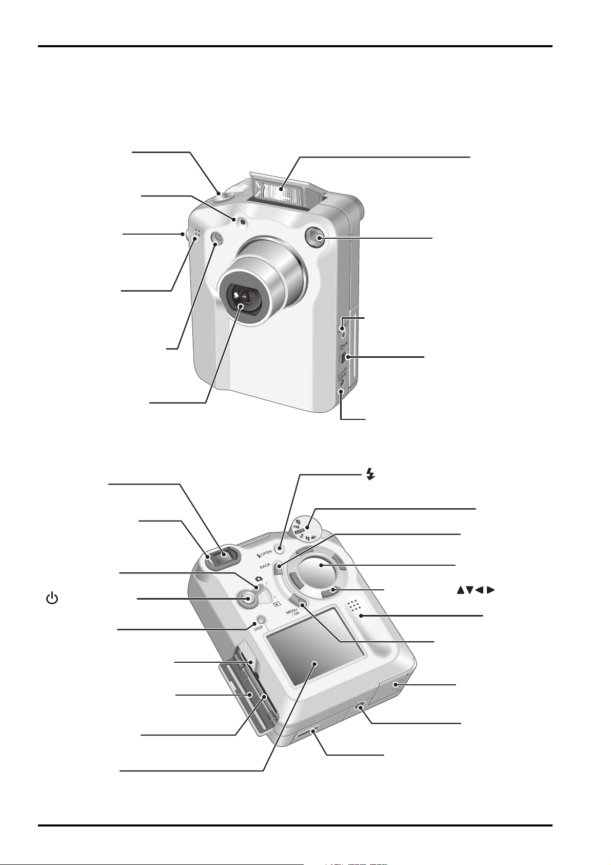
2-1.Names of External Components
FinePix4800Zoom(U/E/EG) SERVICE GUIDE
Shutter button
Self-timer lamp
Strap mount
Microphone
Flash control sensor
Lens/Lens Cover
Flash
Viewfinder window
A/V OUT(audio/visual output)
socket
Digital(USB)socket
DC IN 5V(power input)socket
Viewfinder
Viewfinder lamp
Mode switch
Power button
DISP button
SmartMedia slot cover
release button
SmartMedia slot cover
SmartMedia slot
LCD monitor
OPEN(Flash pop-up)button
Mode dial
BACK button
Display panel
4-direction( )button
Speaker
MENU/OK button
Battery cover
Tripod mount
Cradle connection socket /
Connection socket cover
6
FinePix4800Zoom(U/E/EG) SERVICE GUIDE
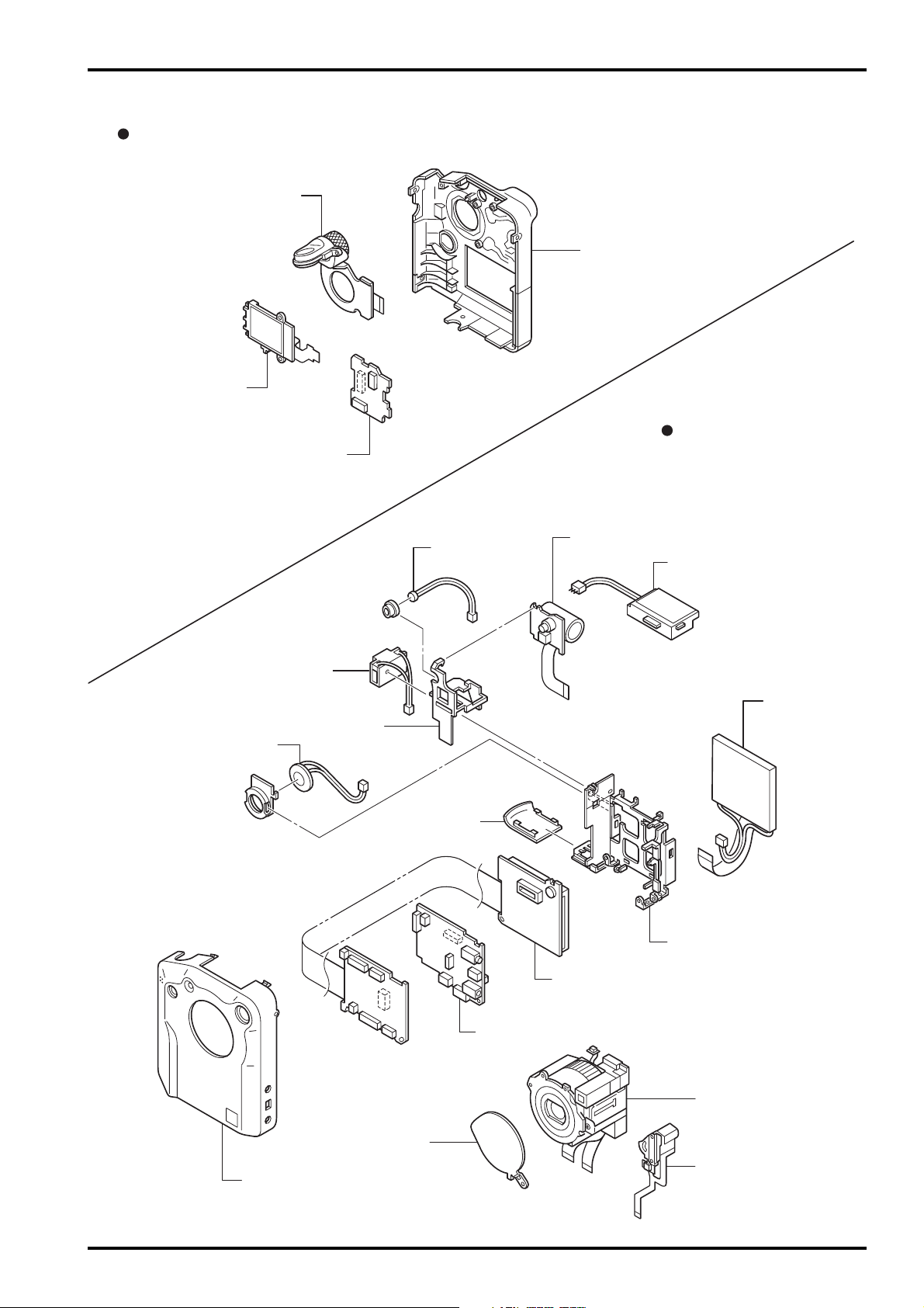
2-2.Names of internal Components
R PANEL
MODE DIAL ASSY
B/W LCD
KEY PWB ASSY
2. Names of Components
R PANEL ASSY
F PANEL
BATTERY CONNECTOR
PWB HOLDER
SPEAKER ASSY
MIC ASSY
B COVER ASSY
ST PWB UNIT
XE PWB UNIT
LCD
M FRAME ASSY
MAIN PWB ASSY
LENS BARRIER
F PANEL ASSY
DC PWB ASSY
LENS CONST
BARRIER MOTOR HEAD
7
3. Disassembly
FinePix4800Zoom(U/E/EG) SERVICE GUIDE
3. Disassembly
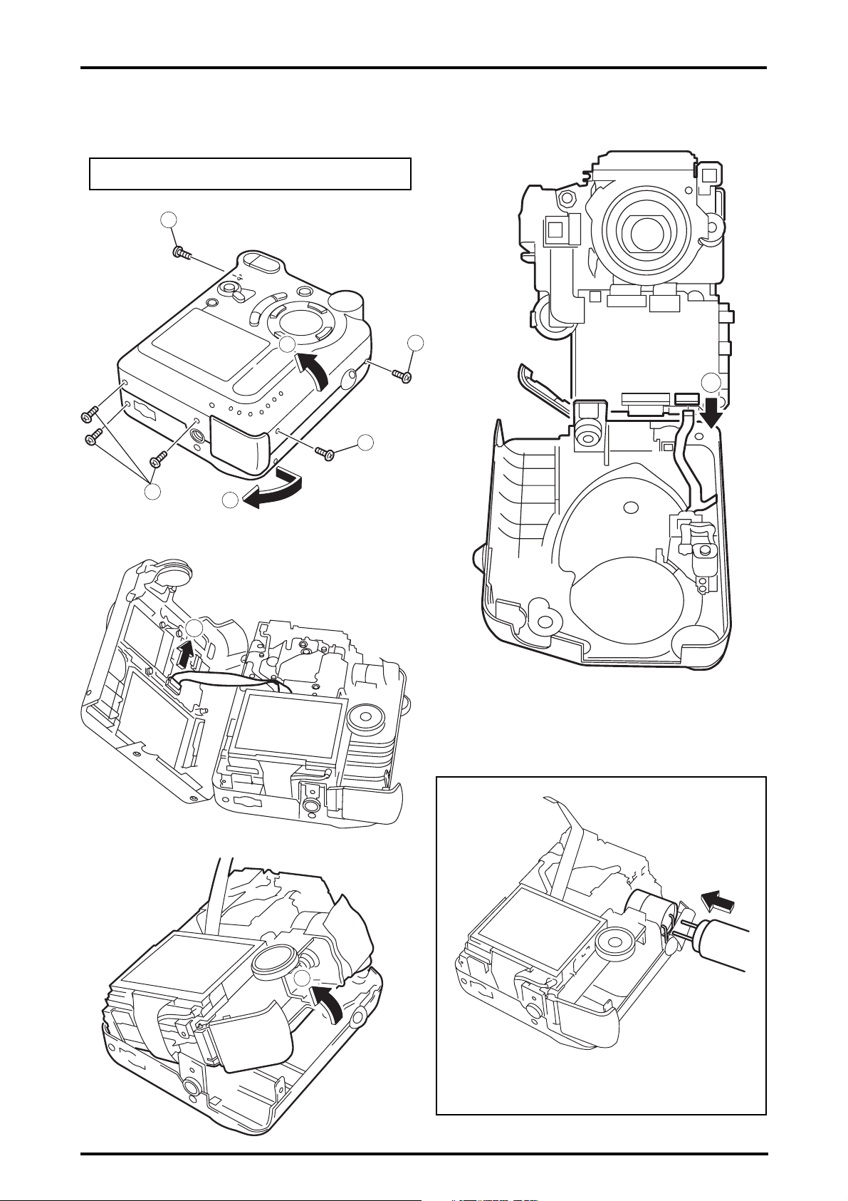
3-1.Removing R PANEL ASSY/ F PANEL ASSY
Remove in the order indicated by circled numbers.
<step1>
<step2>
1
5
3
2
4
<step4>
1
8
<step3>
6
7
< attention >
Thing to remove F PANEL after flash is discharged
8
FinePix4800Zoom(U/E/EG) SERVICE GUIDE
r
3. Disassembly
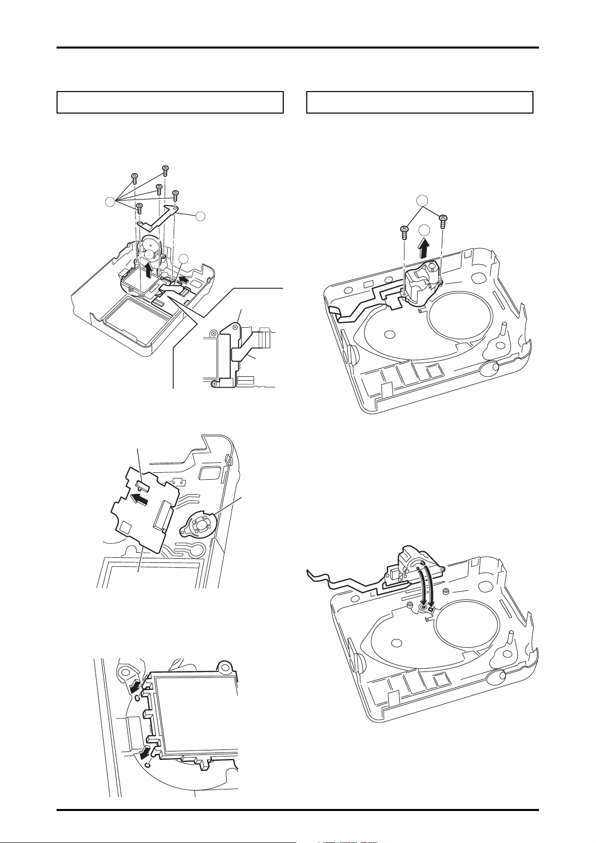
3-2.Removing MODE DIAL ASSY,B/W LCD,
KEY PWB ASSY
Remove in the order indicated by circled numbers.
* Refer to the decomposition procedure of "3-1 F PANEL/
R PANEL" even for the undermentioned procedure.
<step1>
2
3
4
1
SW Frame
3-3.Removing BARRIER MOTOR HEAD,
LENS BARRIER
Remove in the order indicated by circled numbers.
* Refer to the decomposition procedure of "3-1 F PANEL/
R PANEL" even for the undermentioned procedure.
<step1>
1
2
LCD
FFC
KEY PWB
< attention >
Fit the boss of the B/W LCD to the hole of MODE DIAL ASSY.
SW801
RP Leve
KEY PWB
ASSY
< attention >
When KEY PWB ASSY is installed on R PANEL ASSY, the
position of the RP lever of SW901 and R PANEL is noted.
< attention >
When BARRIER MORTOR HEAD is installed on F PANEL,
the position of the hole of the barrier drive axis of MORTOR
and LENZ BARRIER is noted with LENZ BARRIER shut.
9

3. Disassembly
FinePix4800Zoom(U/E/EG) SERVICE GUIDE
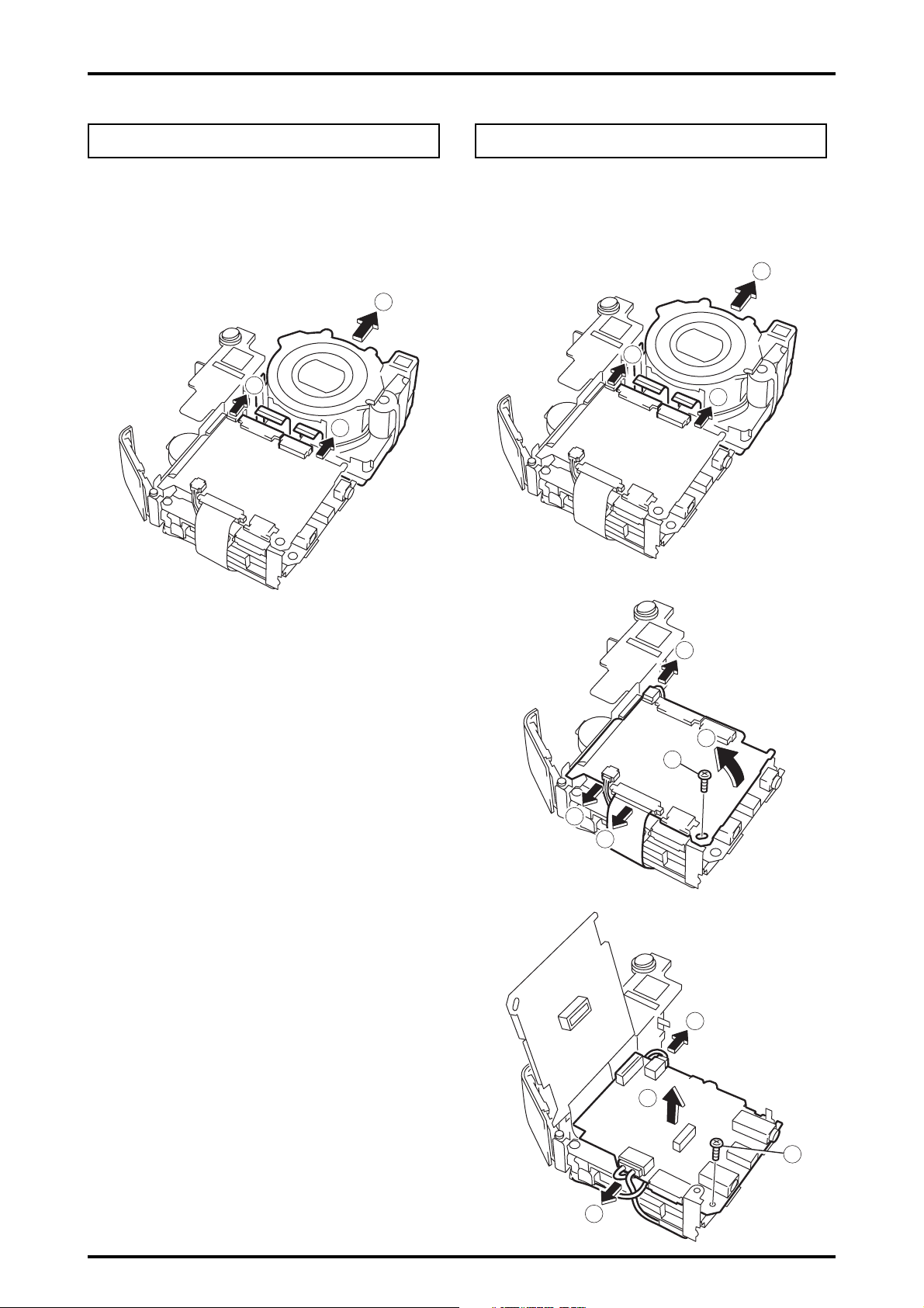
3-4.Removing ST PWB UNIT,XE PWB UNIT
Remove in the order indicated by circled numbers.
* Refer to the decomposition procedure of "3-1 F PANEL/
R PANEL" even for the undermentioned procedure.
<step1>
1
<step2>
<step4>
5
6
< attention >
After ST PWB UNIT is installed, the harness of MIC ASSY
is assembled through the lower side of capacitor (C819).
<step3>
MIC ASSY
2
< attention >
Thing to install ST SHEET surely
4
3
ST SHEET
10
FinePix4800Zoom(U/E/EG) SERVICE GUIDE
3. Disassembly
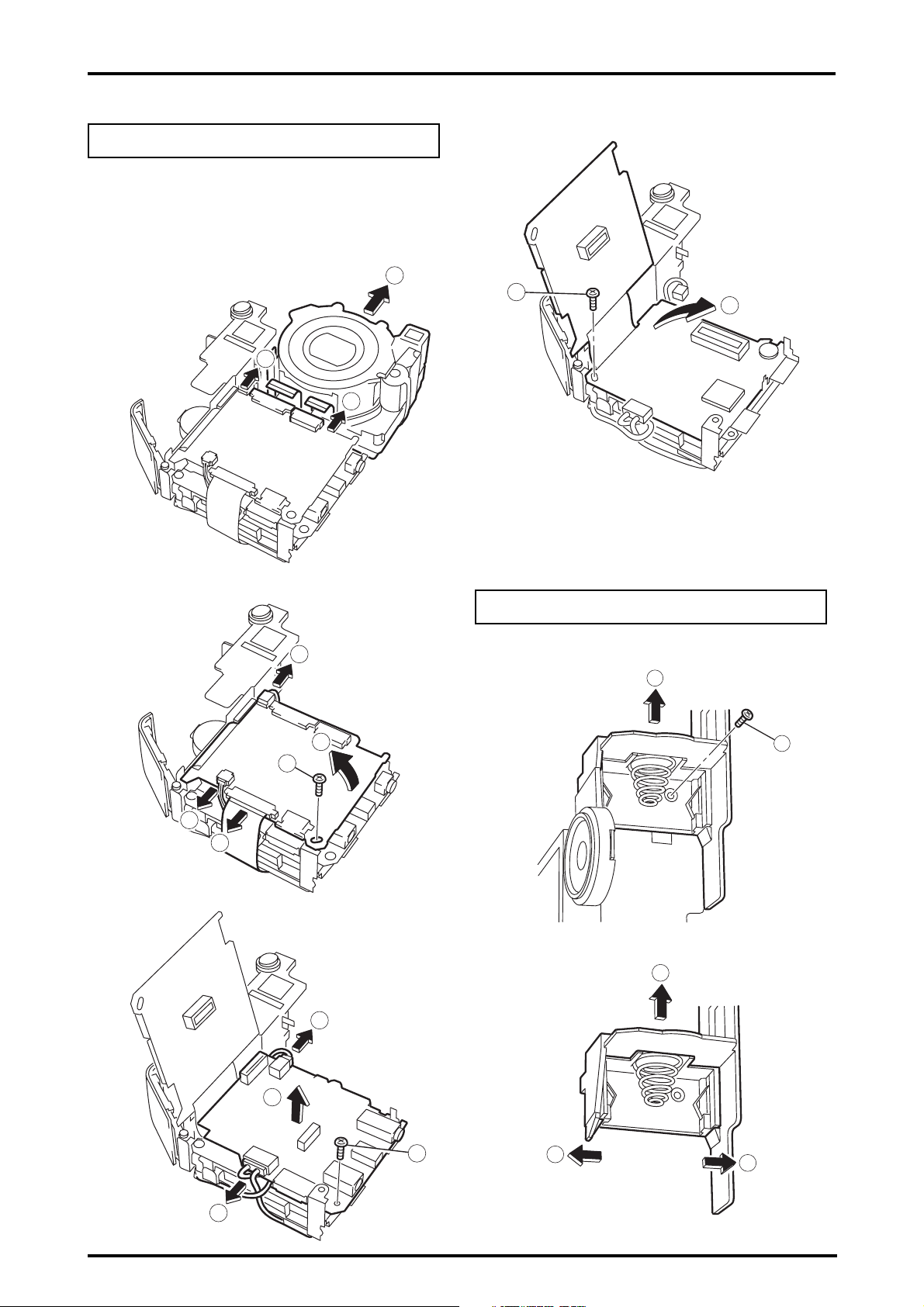
3-5.Removing LENS CONST 3-6.Removing DC PWB ASSY
Remove in the order indicated by circled numbers.
* Refer to the decomposition procedure of "3-1 F PANEL/
R PANEL" even for the undermentioned procedure.
<step1>
2
1
1
Remove in the order indicated by circled numbers.
* Refer to the decomposition procedure of "3-1 F PANEL/
R PANEL" even for the undermentioned procedure.
<step1>
1
2
1
<step2>
<step3>
5
7
6
3
4
9
11
10
8
11
3. Disassembly
3-7.Removing MAIN PWB ASSY
Remove in the order indicated by circled numbers.
* Refer to the decomposition procedure of "3-1 F PANEL/
R PANEL" even for the undermentioned procedure.
FinePix4800Zoom(U/E/EG) SERVICE GUIDE
<step4>
<step1>
<step2>
2
12
1
1
13
3-8.Removing BATTERY CONNECTOR,
PWB HOLDER
Remove in the order indicated by circled numbers.
5
<step1>
2
<step3>
7
6
3
4
<step2>
4
9
11
10
3
1
3
12
8

FinePix4800Zoom(U/E/EG) SERVICE GUIDE
4. Adjustment and Inspection
4. Adjustment and Inspection
4-1. Important point Adjustment when Replacing Major Parts
Check and adjust of the items indicated by O in the table below when replacing the main PWB assembly,
DC PWB assembly, ST CONST, ST PWB unit, XE PWB unit, lens CONST, mode dial assembly, and B/W
LCD.
Note that adjustment is not required when units other than those shown below are replaced.
Adjustments
Mode dial/battery adjustment
DC jack voltage adjustment
Display LCD adjustment
CCD defect data/OFD adjustment (*3)
Picture adjustment
AF adjustment
Flash adjustment (*2)
End setting Required for all when replacing and adjusting the above parts. See P19 and P29 for details of termination setting.
*1 Adjust in the following order when replacing the Lens CONST.
CCD defect data write/OFD adjustment → Picture adjustment → AF adjustment → Flash adjustment
*2 Adjust the Flash following Picture adjustment.
*3 As the CCD defect data is supplied as a pair with the CCD, the CCD defect data cannot be attached to the main
PWB assembly supplied as after-service parts. When replacing the main PWB assembly therefore, the method of
adjustment (method of repair) for ‘CCD defect data write/OFD adjustment’ is as follows.
(1) Remove the EEPROM (IC314) from the main PWB assembly of the unit to be repaired.
(2) Install the EEPROM (IC314) removed in (1) in the after service main PWB assembly.
(3) Make all adjustments other than CCD defect data write/OFD adjustment.
Replacement parts
MAIN PWB(*3) DC PWB ST CONST ST PWB XE PWB
LENS CONST(*1)
MODE DIAL B/W LCD
4-2. Preparations for Adjustment
4-2-1. Required Measuring Equipment
Measuring equipment Remarks
Monitor TV
Regulated power supply
Pattern box PTB450 or equivalent
Waveform monitor Used for function checks
Digital voltmeter
PC Used for various adjustments and operation checks (PC-AT compatible, Windows 98)
Brightness meter LS-110 (Minolta) or equivalent
Color temperature meter Color Meter IIIF (Minolta) or equivalent
4-2-2. List of Jig Used
Productname/type name Pats.No Use Remarks
FilterLB140 ZJ00006-100 Camera System adjustments Common with the DS-30/DS-20/DS-7
AF Chart ZJ00477-100 AF adjustment Common with the FInePix6800Zoom
Close_up lens(f=600mm) ZJ00007-100 AF adjustment Common with the 8mmVTR/MX500/MX600
Lens holder ZJ00008-100 AF adjustment Common with the 8mmVTR/MX500/MX600
Stand ZJ00009-100 AF adjustment Common with the 8mmVTR/MX500/MX600
Base plate ZJ00010-100 AF adjustment Common with the 8mmVTR/MX500/MX600
Gray Chart(Reflective type) ZJ00254-100 Flash adjustmen Common with the MX700/MX500
USB cable FZ03529-100 For PC adjustment Common with the FinePix4700zoom
CD-ROM FZ04059-101 For inspection bundled software
Power cable jig ZJ00213-100 System adjustment Common with the DS-10/FinePix1500
FinePix4800Zoom ZJ00494-100 For PC adjustment Operates only on Win98 English OS
PC adjustment software
AC adapter(AC-5VH) ----------------- Adjustment overall Accessories
DSC jig driver setup ZJ00476-100 For PC setup DSC jig driver setup
Li BATT jig ZJ00226-100 System adjustment Common with the MX1700
13

4. Adjustment and Inspection
FinePix4800Zoom(U/E/EG) SERVICE GUIDE
4-2-3.Measuring Intrument and Jig Connection Diagram
Power supply cable jig
FinePix 4800Z
Regulated power
supply (Note 2)
DC IN terminal
USB terminal
Battery jig
DC5V
PC
DC5V
Regulated power
supply (Note 2)
Note 1: Always check the input voltage in the vicinity of the DC IN terminal when adjusting.
Notes 2: Adjustment is possible even with a single regulated power supply.
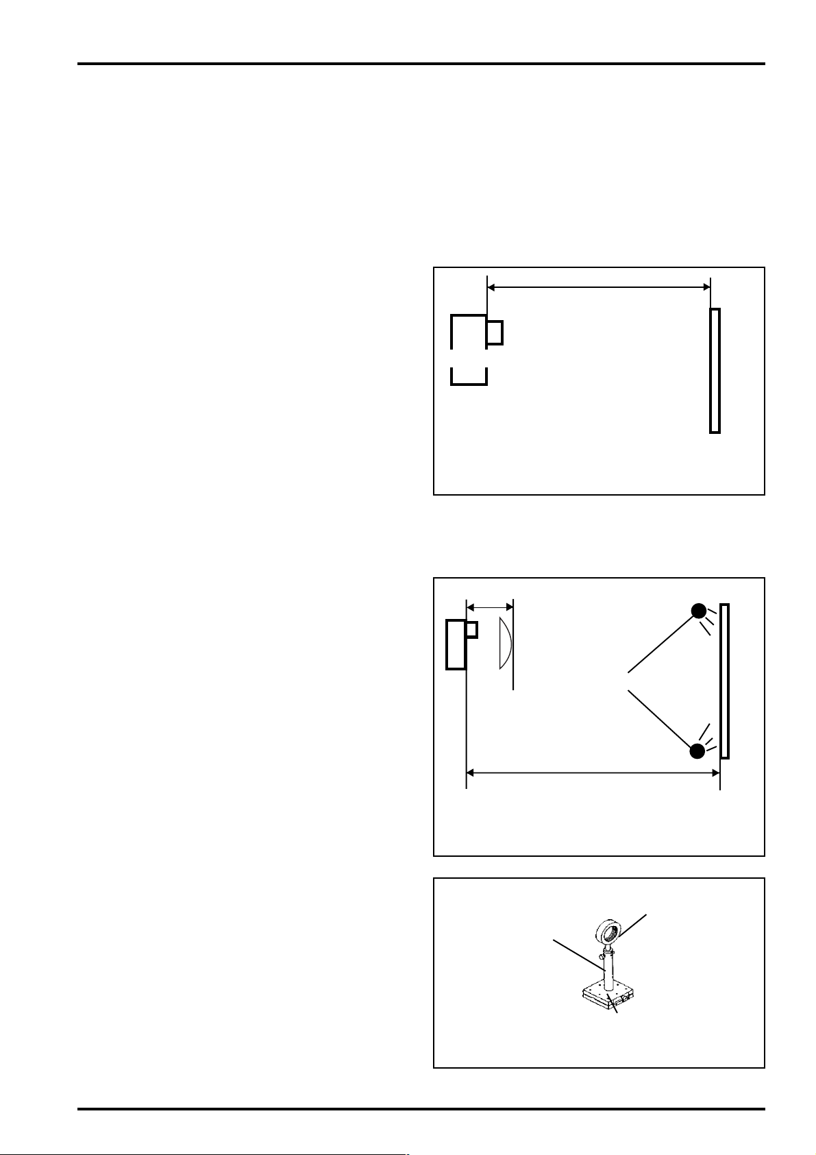
4-2-4. Setup for adjustment
(1) Preparatory setup for Picture adjustment
(Fig.A)
<White pattern>
Adjust the distance between the reference face of
the camera (see *1) and the filter (LB140) to
30±5mm, and adjust the distance between the filter
(LB140) and the pattern box to a maximum of
50mm. Pattern box specifications are as follows.
1. Brightness:
160±5cd/m2 (with LB140 filter)
No chart, center of pattern box
Minolta brightness meter LS-110 or equivalent
* Measurement
Place the filter (LB140) against the pattern box.
With the filter (LB140) in contact with the brightness
meter, adjust the pattern box brightness to 160±5cd/
m2.
Voltmeter
(Note 1)
(sensing)
30±5mm
Camera
Filter (LB140)
<Fig.A> Preparations for Picture Adjustment
Up to 50mm
Pattern
box
2. Color temperature:
6100 ± 50 K (with LB140 filter)
No chart, center of pattern box
Minolta color meter IIIF or equivalent
14
FinePix4800Zoom(U/E/EG) SERVICE GUIDE
* Measurement
Place the filter (LB140) against the pattern box.
With the filter (LB140) in contact with the color temperature meter, adjust the pattern box color tempera-
ture to 6100 ± 50 K.
*1: The camera reference face is the front face on the outside of the camera.
4. Adjustment and Inspection
(2) Preparations for Flash adjustment (Fig.B)
As Flash adjustment is easily affected by external light, the area around the gray chart should
be as dark as possible.
The chart is mounted at a distance of 100 cm
from the reference face of the camera (see *1).
An Oxford Gray (No.22) chart (manufactured by
Superior) with a reflectivity of 18±0.7% is used
as the gray chart.
Camera
100cm
Gray chart
(3) Environment setup for AF adjustment
(Fig.C)
1) The distance from the reference face (see *1)
to the AF chart is 620±5mm for both the INF
adjustment and 600mm adjustment, however
with INF adjustment a 600mm conversion lens
is fitted at 30±5mm from the reference face
(see *1). The conversion lens is not used with
600mm adjustment.
2) Illuminate the AF chart with the light source.
Ensure that the brightness at the surface of
the AF chart is 9.0~12.0Ev.
3) Locate the conversion lens concentric with the
camera lens.
<Fig.B> Preparations for Flash Adjustment
AF chart
30±5mm
Fluorescent lamp stand
O f=600mm conversion lens
620±5mm at INF adjustment
620±5mm at 600mm adjustment
<Fig.C> AF Adjustment Environment
Stand (∑-32-130/Sigma
Optical Equipment)
Conversion Lens Unit
Lens holder (∑-40-50/
Sigma Optical Equipment)
Baseplate
( ∑-13-3/Sigma Optical
Equipment)
15
4. Adjustment and Inspection
4-2-5. Various downloading software decompressions,
preservation methods, and notes
The firmware and the PC adjustment software are in a specified Web server, and both of these are the compression of ZIP
form files.
Therefore, after downloading these compression files from the
Web server, the decompression of the file is necessary.
In the decompression software, if the decompression of the
ZIP form can be done, any software is OK.
(Please prepare each one for the decompression software.)
The decompression and the preservation method of the PC
adjustment software and the firmware are described
to the following.
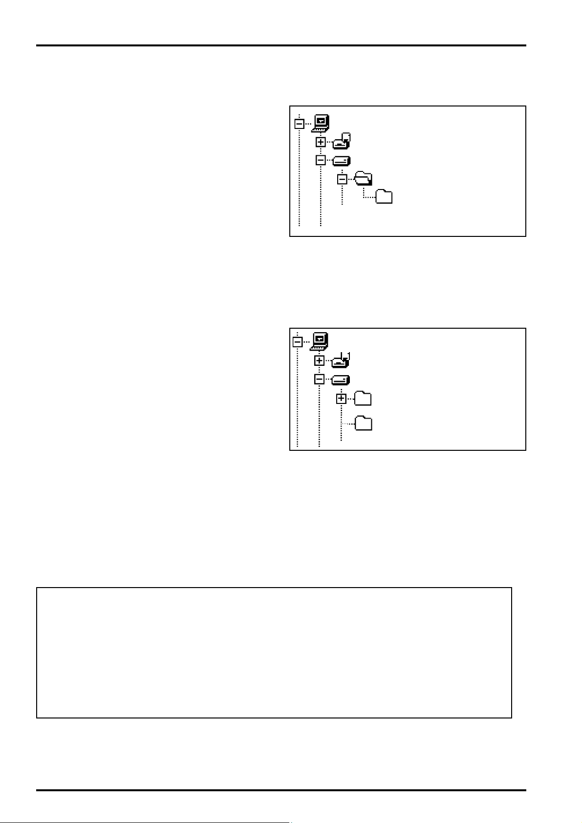
(1) The PC adjustment soft decompression and preservation method
<step1>
Download compressed PC adjustment software (ZJ00494-
100.ZIP) from Web server (http://fujifilm-di.intranets.com/).
FinePix4800Zoom(U/E/EG) SERVICE GUIDE
My Computer
3.5inch FD(A:)
(C:)
ZJ00494-100
FinePix4800ZU_E
<Fig.D-1>
<step2>
Defrost the downloaded compression software.
(Note)
*Specify the preservation drive for C drive if it is decompression software which can specify the preservation drive.
*Similarly, defrost without making a new folder if it is decompression software which can be defrosted without making a
new folder.
*Defrost simply if the decompression software which you have
cannot specify the drive specification and the folder making.
<step3>
The folder named ZJ00494-100 can be made by defrosting
without specifying anything. <Fig.D-1>
Then, copy the folder named FinePix4800ZU_E in this folder
in C drive.(Fig.D-2)
The folder of ZJ00494-100 becomes unnecessary at the end,
and delete this folder.
My Computer
3.5inch FD(A:)
(C:)
ZJ00494-100
FinePix4800ZU_E
<Fig.D-2>
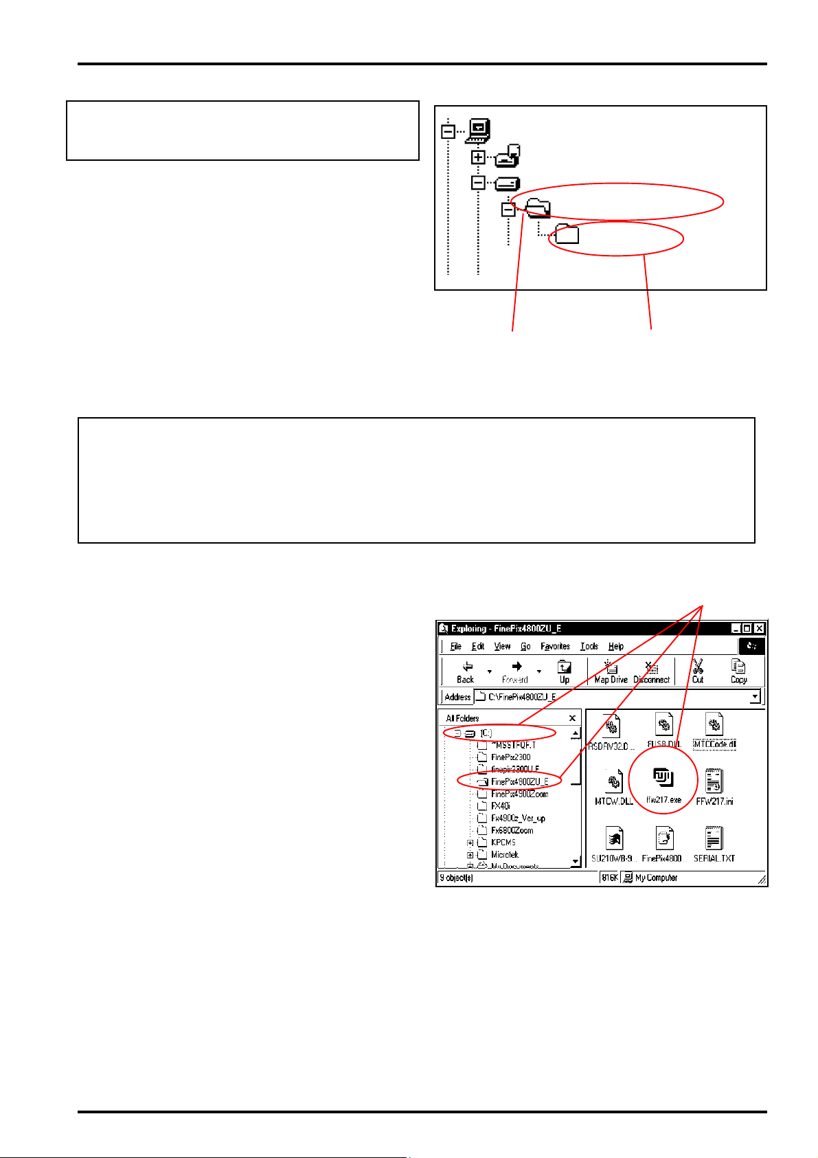
(Caution)[Important]
(a) PC adjustment software can not start when there is folder of
FinePix4800ZU_E in folder named ZJ00481-100.(Fig.D-1)
Please preserve the folder of FinePix4800ZoomU_E right under C drive.(Fig.D-2)
(b) Please do not change the foldername named FinePix4800ZU_E.
PC adjustment software can not start when foldername is changed.
16
FinePix4800Zoom(U/E/EG) SERVICE GUIDE
(2) Firmware decompression and preservation method
4. Adjustment and Inspection
Please disregard the undermentioned content
(STEP3 from STEP1) until the download of the
firmware is instructed.
<step1>
Download compressed firmware (ZJ00482-100.ZIP*1) from
Web server (http://fujifilm-di.intranets.com/).
(*1)
ZJ00482-100 described here is a part number of
FinePix2300(U_E_EG).The part number is separately notified
when the download of the firmware is needed in
FinePix4800Zoom(U_E_EG).
<step2>
Defrost the downloaded compression software
<step3>
As the folder named ZJ00482-100 can be made by simply
defrosting;(Fig.D-3-(1)) All files are copied in Smart Media in
this folder including the folder named imfidx10(Fig.D-3-(2))
<Fig.D-3>
(Caution)[Important]
(a) Download should use Smart Media.
(b) Please format Smart Media with the camera.
My Computer
3.5inch FD(A:)
(C:)
ZJ00482-100
imfidx10
(1)
(2)
(c) When the folder named imfidx10 is changed, the firmware cannot be downloaded.
4-2-6.Install the DSC jig driver and the PC adjustment
software.
* Since this camera uses the USB for communications with the
personal computer, in order to start the PC adjustment soft-
ware, [the DSC jig driver] needs to be installed in the personal
computer beforehand.
* The DSC jig driver is the same as that for the FinePix 6800Z,
so if this jig driver software is already installed in the personal
computer, it is not necessary to install it.
The procedure is given below.
(1)Installation of DSC jig driver
<step 1>
DSC jig driver(ZJ00476-100.ZIP) is downloaded from Web
server (http://fujifilm-di.intranets.com/).
<step 2>
Defrost the downloaded compression software
<step 3>
Double-click setup.exe in the folder of defrosted ZJ00476-
100 and install Fuji FILM DSC Jig Driver as follows.
<step 4>
Install the software in [C:\ProgramFiles\Fjig]
according to the instructions on the PC's screen.
<Fig.D-4> ffw217.exe screen display (Windows Explorer)
(1)
(2)Startup of PC adjustment software
When the folder has been copied to the C drive, double-click
on the file C:\FinePix4800ZoomU_E\ffw217.exe (Fig.D-4(1)) to
start the adjustment software.
17
4. Adjustment and Inspection
4-3. Adjustment Using the PC
4-3-1. Setting up the Adjustment Software
* As the initial setup is included in the FFW217.ini file,
follow the procedure described below. Note that the
software will not run if the file name is changed.
* As steps 3~6 in initial setup are included in the
FFW217.ini file, all that is required is to verify details.
* Do not alter the user program (FinePix4800ZoomU_E)
under any circumstances. The software will not
run if it has been altered in any way.
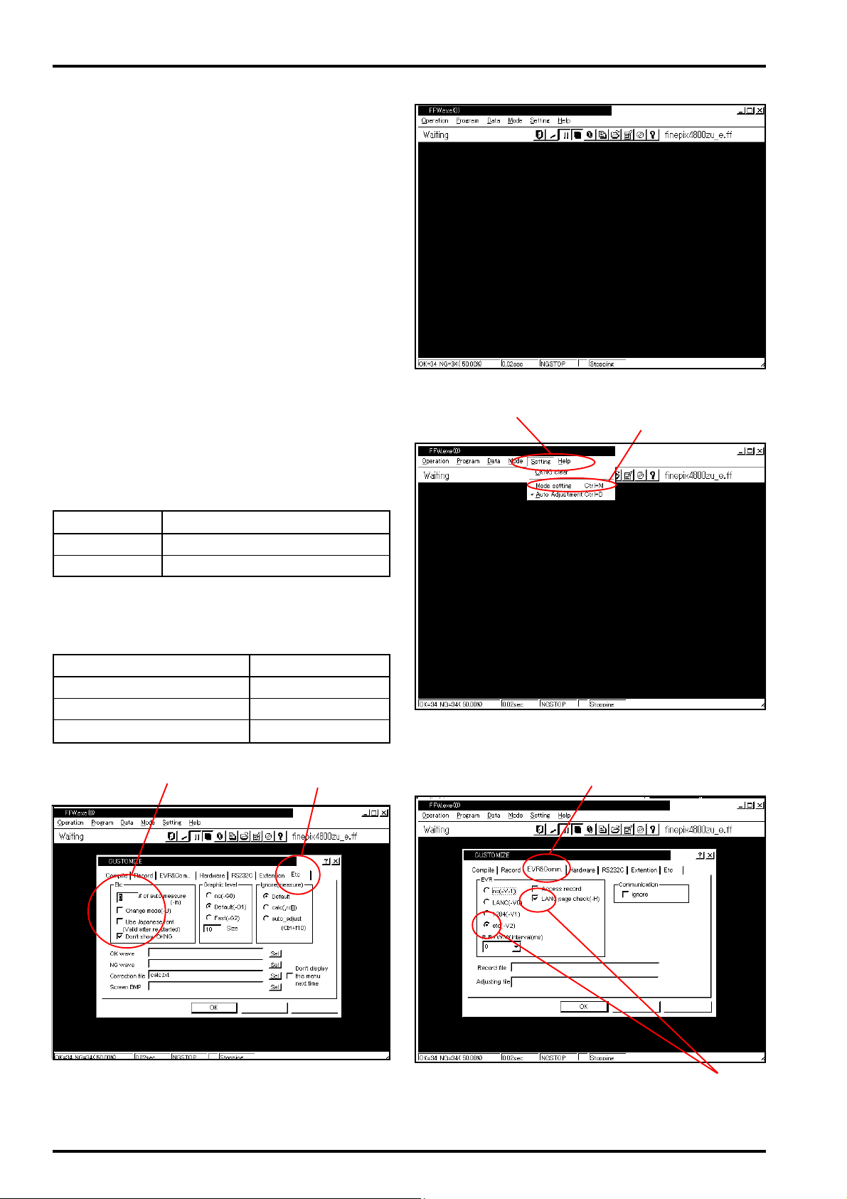
<Step 1>
Double-click on the executable file FFW217.exe
(Fig.D-(1)) to display the FFW Start-up Screen
(Fig.E).
FinePix4800Zoom(U/E/EG) SERVICE GUIDE
<Step 2>
Select the Setting menu (Fig.F-(1)) from the menu
bar on the Menu screen, and then select Mode setting (Fig.F-(2)).
<Step 3>
Select the EVR menu (Fig.G-(1)) from the Customize dialog screen, and setup as follows (Fig.G-(2)).
Item Setup details
etc (-V2) Use (=check)
LANC page Use (=check)
<Step 4>
Select the Etc menu (Fig.H-(1)) from the Customize dialog screen, and setup as follows (Fig.H-(2)).
Item Setup details
Number of automatic measurements
Enable mode change
Use Japanese fonts
No check (=un used)
No check (=un used)
0
<Fig.E> FFWJ217.EXE Start-up Screen
(1)
(2)
<Fig.F> Mode Setting Select Screen
(1)(1)(2)
18
Apply
Apply
<Fig.G> EVR Dialog Box Screen<Fig.H> Etc Dialog Box Screen
(2)
FinePix4800Zoom(U/E/EG) SERVICE GUIDE
4. Adjustment and Inspection
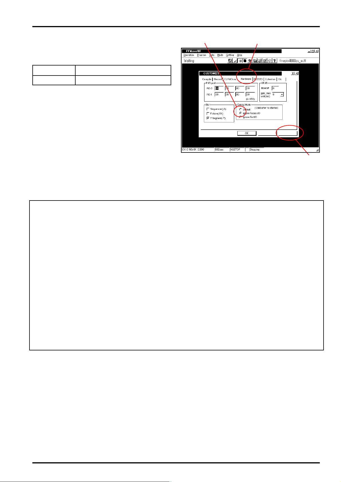
<Step 5>
Select Hardware from the Customize Setup Screen
(Fig.I-(1)). Setup as follows on the Hardware menu
(Fig.I-(2)).
Item Setup. details
Debug mode Select Ignore Focus
<Step 6>
When setup on the three menus noted above (EVR,
Etc, Hardware) is complete, click on Apply (Fig.I-(3))
on the Customize dialog screen to finish.
After the setup has been applied, further setup is unnecessary.
Note:
Setting Disable OKNG Display to OFF on the screen
shown in Fig.H displays OK on the screen if adjustment
is OK, and NG if not (either setting may be entered).
(2)
<Fig.I> Hardware Dialog Box Screen
(1)
Apply
(3)
Cautions When Adjusting
1) Terminal Setting returns the camera from the Jig mode to the Product Mode (see P29).
Terminal Setting is required when using the PC adjustment software, even when replacing boards or units
other than those noted above. Failure to run Terminal Setting will prevent identification as Mass Storage
when the camera is connected to the PC, and prevent communication with the PC.
2) As power from the DC jack, or from the lithium battery jig, may be used for FinePix 4800Z adjustment, it is
possible that the power supply may be changed during adjustment. When changing the power supply, first
remove the DC jack, and then insert the lithium battery jig (or the reverse).
Changing the power supply occurs while the PC adjustment software is running on the start screen (Fig.2, P20).
The PC adjustment software will generate an error if the power supply is changed while it is running, or in
the worst case may result in the PC hanging up.
3) When all adjustment have been completed, always check that the camera is identified as Mass Storage.
4) The values resulting from adjustment as shown on the PC screens ( Fig.4, Fig.6, Fig.7, Fig.10, Fig.15,
Fig.18, Fig.21, Fig.22, Fig.23) on the following pages cannot be used for comparison with adjustment
data.
19
4. Adjustment and Inspection
4-3-2. FFWJ217.EXE Command Description
Menu Command Details
Operation Start Program start
Stop Program stop
Temporary stop Temporary program stop
Step 0 Do not use
End Terminate program
Program Reload Program (*.ff) reload
Select Program (*.ff) select
Edit Program (*.ff) edit
Data ad[ ] Do not use
rd[ ] Do not use
SW Do not use
fsw Do not use
EVR Data write/read from
EEPROM (see 4-3-6.)
Mode File record Do not use
NGSTOP Program stopped if
adjustment is NG
STEP Do not use
LINE Do not use
AUTO Do not use
Setting OKNG clear Do not use
Mode set Sets up mode
Automatic adjustment
Help Help Basic software help
FF help User program help
Focus Not used with this
Version Version information for
<Table 1> FFWJ217.exe Commands
Execution setting for Auto
Adjust in user program
adjustment software
basic software
FinePix4800Zoom(U/E/EG) SERVICE GUIDE
Item
10/16
ROM
ROM
+1
-1
FD symbol
All RD (green
text)
All RD (pink
text)
PAGE
ADDR.
→
→
<Table 2> EVR Data Display Commands
Details
Decimal ↔ Hexadecimal
conversion
Redraw
Read ROM
Write ROM
+1 & RAM write (data not
written to F_ROM)
-1 & RAM write (data not
written to F_ROM)
Record
ROM screen ROM
data read
RAM screen RAM
data read
Page specification
Addres specification
(1)
(2)
Decimal ↔ hexadecimal conver-
sion of EVR data
Redisplay EVR data
Read data from F-ROM
Write data to F-ROM
Decrement specified
data by 1
Decrement specified
data by 1
Save EVR data
One page (address
256h) of data
One page (address
256h) of data
Page specification
(move to specified page)
Addresses specification
(move to specified address)
Description
* Do not alter the user program (FinePix 4800ZU_E) un-
der any circumstances. The software will not run if
it has been altered in any way.
4-3-3. Writing and Reading From the
EEPROM
This adjustment software may be used in the same
manner as the adjustment remote (RM95B) to write
and read data from the EEPROM. Use the following
procedure.
<Step 1>
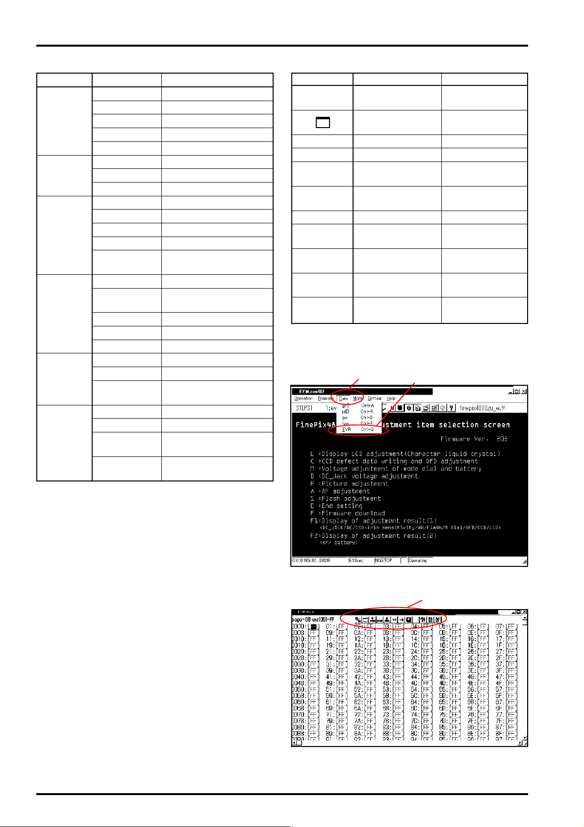
Display the screen for selection of PC-camera adjustment items (see P20).
<Step 2>
Select Data--->EVR from the menu on the Adjustment Items Select Screen (Fig.J-(1)--->Fig.J-(2)).
<Step 3>
EVR Data is displayed (Fig.K). See Table 2 above
for details of the EVR Data menu bar (Fig.K-(1)).
<Fig.J> EVR Write/Read Display Screen
(1)
<Fig.K> EVR Write/Read Operation Screen
20
FinePix4800Zoom(U/E/EG) SERVICE GUIDE
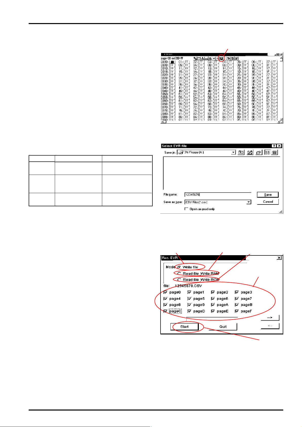
<Step 4> (select file save location)
Select FD Symbol (Fig.L-(1)) from the EVR data
dialog. This displays the EVR File Select Screen
(Fig.M). Select the save location on the screen.
This example shows selection of Drive: A (floppy
disk) as the save location. Enter the file name for
the data and click on Save. This operation opens
the EVR Record dialogue (Fig.N).
<Step 5> (batch data read)
Select Write file (Fig.N-(1)) on the EVR Record
Dialog Screen, check page0~pageF (Fig.N-(4)),
and click on the Open button (Fig.N-(5)).
This operation opens Read Data From Specified
Page in Camera (adjustment data for
FinePix4800Zoom is located in page0~pageF).
* Modes in EVR Record Dialog
Item
Write file
Read file/
WriteRAM
Read file/
WriteROM
Details
Save data in flash
ROM to file
Write data saved in
file to RAM (not written to ROM)
Write data saved in
file to ROM
Remarks
RAM, EVR data displayed in blue after
writing to RAM.
RAM, EVR data displayed in
red after writing to RAM.
4. Adjustment and Inspection
(1)
<Fig.L> EVR Data Dialog Screen
<Step 6> (batch write (write to RAM))
Select the file saved in Step 5, check Read file/Write
RAM (Fig.N-(2)) on the EVR Record Dialog Screen,
and click on the Start button (Fig.N-(5)). A check as
shown in Fig.N-(4)) is unnecessary at this point. The
data in the file saved on the PC is automatically written to RAM. The data written to RAM is displayed in
blue.
<Step 7> (batch write (write to ROM))
Select the file saved in Step 5, check Read file/Write
ROM (Fig.N-(3)) on the EVR Record Dialog Screen,
and click on the Start button (Fig.N-(5)). A check as
shown in Fig.N-(4)) is unnecessary at this point. The
data in the file saved on the PC is automatically written
to ROM. The data written to ROM is displayed in red.
<Fig.M> File Save Location Select Screen
(1)
(2)
(3)
(4)
(5)
<Fig.N> EVR Record Dialog Screen
21
 Loading...