

Page 1
USER’S GUIDE
Third Edition
FNA
053DC514C
Page 2

INTRODUCTION
In order to get the most from your PosterPrinter 3000,
it is recommended that you read the instruction manual thoroughly before
usage, and follow all instructions carefully. Keep the manual close at
hand for future reference.
FCC
NOTE: This equipment has been tested and found to comply with the limits for a Class A digital device,
pursuant to part 15 of the FCC Rules. These limits are designed to provide reasonable protection against
harmful interference when the equipment is operated in a commercial environment.
This equipment generates, uses and can radiate radio frequency energy and, if not installed and used in
accordance with the instruction manual, may cause harmful interference to radio communication. Operation of
this equipment in a residential area is likely to cause harmful interference in which case the user will be
required to correct the interference at his own expense.
CAUTION: Changes or modifications not expressly approved by the party responsible for compliance could
void the user’s authority to operate the equipment.
EMC (Electromagnetic Compatibility Notice)
This Class A digital apparatus meets all requirements of the Canadian Interference Causing Equipment
Regulations .
Cet appareil numerique de la classe A respecte toutes les exigences du Reglement sur le material broilleur du
Canada.
Page 3

CONTENTS
CONTENTS ..................................................................................................... 1
1. BEFORE USING YOUR POSTERPRINTER 3000 ................................................ 2
CHECKLIST OF ITEMS INCLUDED IN PACKAGE..............................................2
UNP A CKING THE PRINTER................................................................................ 2
INSTALLATION SPACE ........................................................................................3
CONNECTING THE POWER CORD ...................................................................3
SAFETY PRECAUTIONS.....................................................................................4
INSTRUCTIONS FOR PROPER USE OF THE PRINTER................................... 6
MAIN FEATURES OF THE POSTERPRINTER 3000 ..........................................7
2. INDIVIDUAL PART NAMES ............................................................................ 8
FRONT VIEW ....................................................................................................... 8
REAR VIEW..........................................................................................................8
SCANNER ............................................................................................................9
PRINTER.............................................................................................................. 9
CONTROL PANEL..............................................................................................10
3. BEFORE PRINTING .................................................................................... 12
INSTALLING PAPER .......................................................................................... 12
PROPER USE OF THE CUTTER ...................................................................... 13
4. BASIC FUNCTIONS .................................................................................... 14
PRINTING IN NORMAL MODE..........................................................................14
PRINTING IN PHOTO MODE ............................................................................ 16
PRINTING IN REVERSE MODE........................................................................ 17
1
2
3
4
5
5. PRINTING DIFFERENT POSTER SIZES .......................................................... 18
DIVISION PRINTING..........................................................................................18
PRINTING POSTERS SMALLER THAN THE PAPER SIZE ..............................20
PRINTING BANNERS FROM LONG INPUT DOCUMENTS ............................. 21
6. ADDITIONAL FUNCTIONS ........................................................................... 22
FUNCTION MODE ............................................................................................. 22
REMAINING PAPER MODE...............................................................................24
7. SCANNING/PRINTING AREAS ..................................................................... 26
SCANNING AREA (for letter-size originals) ....................................................... 26
PRINTING AREA................................................................................................26
8. SUPPLIES ................................................................................................ 27
DESCRIPTION ...................................................................................................27
POINTS TO NOTE WHEN USING POSTERPRINTER SUPPLIES ...................28
REMOVING INK FILM FROM THERMAL TRANSFER AND HDP PAPER ........28
9. TROUBLESHOOTING .................................................................................. 29
ERROR MESSAGES AND RESPONSES..........................................................29
TROUBLESHOOTING........................................................................................ 30
10. CLEANING THE PRINTER .......................................................................... 32
PRINTER............................................................................................................ 32
SCANNER ..........................................................................................................33
6
7
8
9
10
SPECIFICATIONS ........................................................................................... 34
INDEX.......................................................................................................... 35
1
Page 4

BEFORE USING YOUR POSTERPRINTER
3000
CHECKLIST OF ITEMS INCLUDED IN PACKAGE
1
Be sure to check that all of the following items have been included in the package.
Main unit
User's guide
Power cord (1) Paper bracket (1) End caps (2)
UNPACKING THE PRINTER
packing materials for shuttle unit
(cardboard)
Caution
• Before switching the printer on, be sure to
remove the cardboard protecting the
shuttle unit and the platen rubber protector.
•When transporting the printer, be sure to
insert these packing materials.
2
platen rubber protector
(cardboard)
Page 5
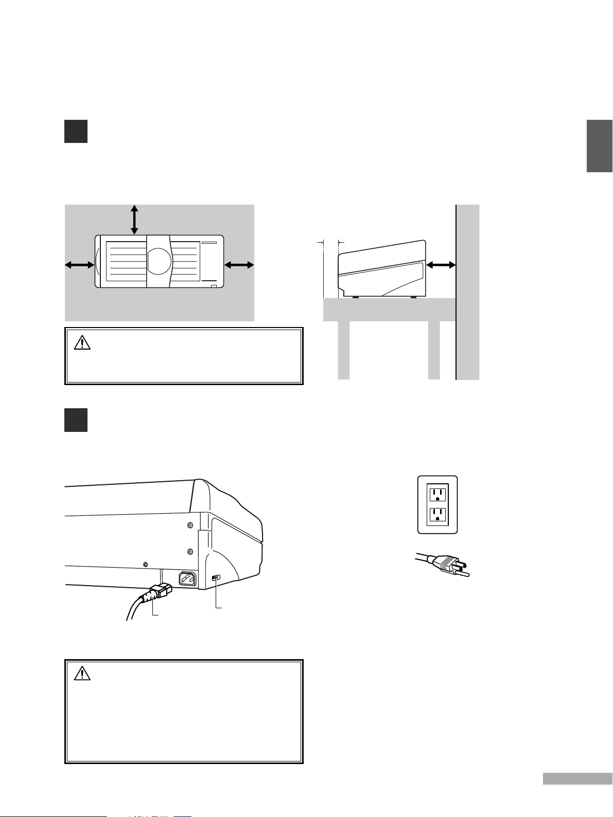
INSTALLATION SPACE
To ensure the proper functioning of your PosterPrinter 3000, it is important to
allow adequate space around the main unit. Install as indicated in the following
diagrams (unit: inch/mm).
8/200
2/50
8/200 8/200 8/200
table
wall
Caution
Be sure to place the printer on a sturdy, flat
surface.
CONNECTING THE POWER CORD
Connect the power cord to the main unit.
Insert the power plug into a wall socket.
1
power cord
power switch
Caution
1. Always connect the power cord to the
printer before inserting the plug of the
power cord into a power socket.
2. When using a two-prong socket, always
connect the grounding wire to a grounding
terminal.
Inserting the plug into a
three-prong socket
3
Page 6
1
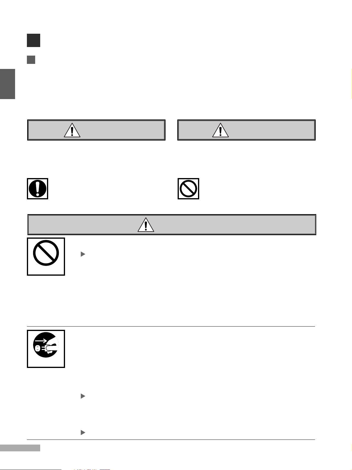
SAFETY PRECAUTIONS
Important
In order to ensure the proper use of the PosterPrinter 3000, the instructions in this manual
have been provided with the following markings to indicate those items designed to prevent
damage to property or injury to users of the printer or persons in the vicinity of the printer.
The degree of damage or injury which may result from a failure to follow the instructions in this
manual properly are classified as follows:
CAUTION WARNING
Improper use of the printer may result in
injury or damage to property.
Improper use of the printer may result in
serious injury or death.
Different types of instructions to be followed have been marked with the following types of
symbols. (Note that other symbols are also used within this manual.)
Items marked with this symbol are instructions for
procedures which must always be undertaken.
An explanatory picture will accompany the symbol.
Items marked with this symbol are warnings against
actions which should never be undertaken.
An explanatory picture will accompany the symbol.
WARNING
• Do not connect the printer to any power source other than one of the specified voltage.
Doing so may result in fire or electrical shock.
Make sure the printer is connected only to a 120-V power source.
• Do not damage, crease or fold the power cord.
WARNING
Altering the power cord, placing heavy objects on it, or allowing it to become damaged,
creased, or folded may result in fire or electrical shock.
• Do not connect the printer to a two-way or multiple-way extension cord.
Doing so may result in fire or electrical shock.
• Never insert or remove the plug with wet hands.
Doing so may result in electrical shock.
• Do not remove the cover from the printer.
Doing so may result in electrical shock.
• Always be sure to hold the plug firmly in your hand when removing it from the power
REMOVING PLUG
• In the event that the printer overheats, begins to emit smoke, or gives off an unusual odor,
• In the event that metal objects, water, or other liquids find their way inside the unit, turn off
4
socket, never do so by simply pulling on the cord.
Pulling on the cord to remove the plug from the power socket or applying excessive force
when doing so may cause damage to the cord, which in turn may result in fire or
electrical shock.
turn off the main power switch immediately and remove the plug from its socket.
Continuing to use the printer even after such problems occur may result in fire or
electrical shock.
If any such problems occur, contact the dealer from whom you purchased your PosterPrinter 3000.
the main power switch immediately and remove the plug from its socket.
Continuing to use the printer even after such problems occur may result in fire or
electrical shock.
If any such problems occur, contact the dealer from whom you purchased your PosterPrinter 3000.
Page 7
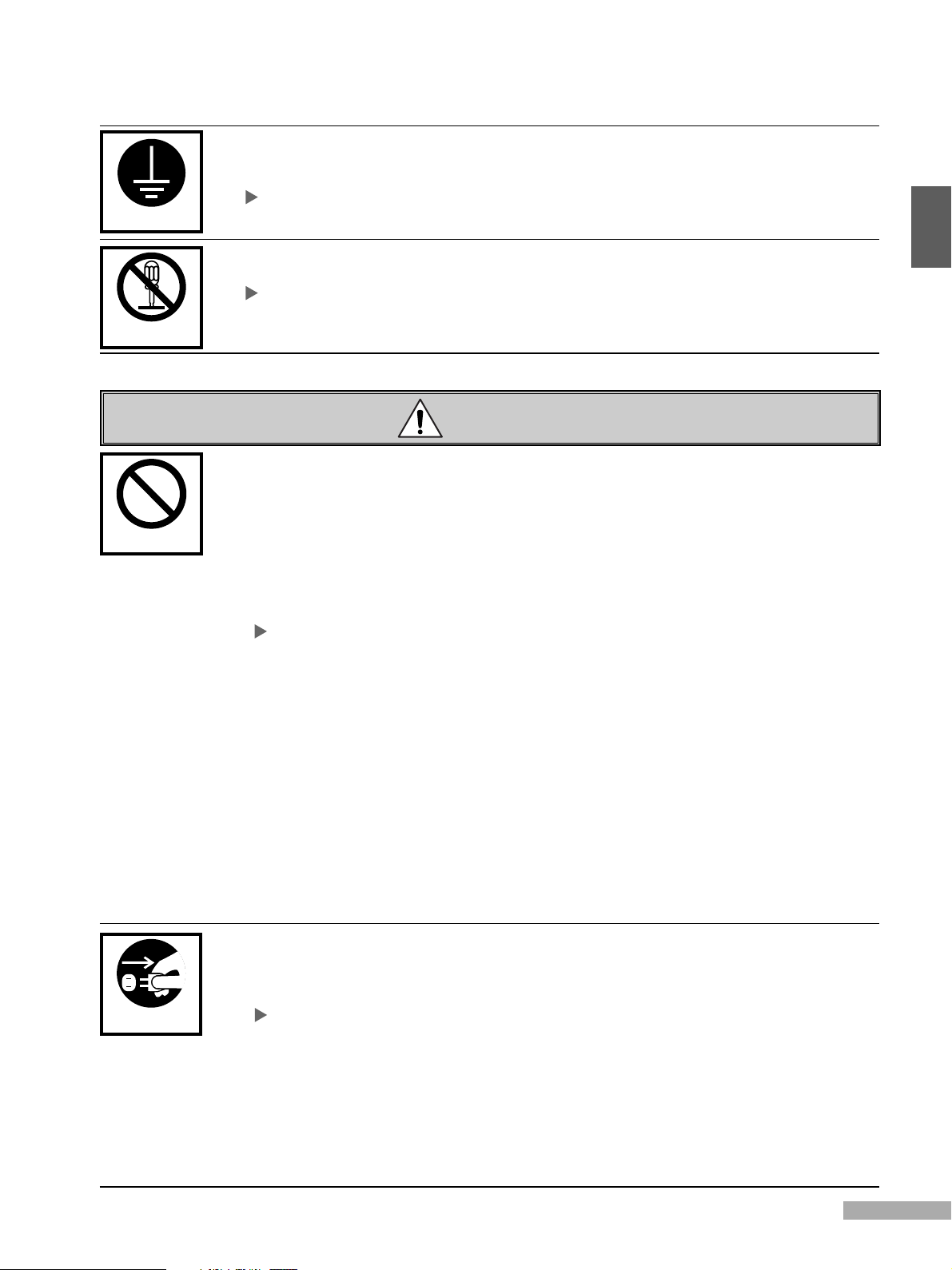
GROUNDING
• Always make sure that the printer is properly grounded.
Failing to do so may cause power leakages, which in turn may result in fire or electrical
shock.
If for some reason you are unable to ground the unit, ask the dealer from whom you purchased your
PosterPrinter 3000 for instructions on how to do so.
DISASSEMBLY
WARNING
• Never disassemble or modify the printer.
Doing so may result in fire or electrical shock.
If the printer breaks down, turn off the main power switch, remove the plug from its socket, and contact the
dealer from whom you purchased your PosterPrinter 3000 to request any necessary repairs.
CAUTION
• Do not place the printer on an unstable surface.
Doing so may cause it to fall, which in turn may result in bodily injury.
• Do not obstruct the ventilation slots.
Doing so may cause the internal temperature of the printer to rise to abnormally high
levels, which in turn may result in fire.
• Do not place vases, potted plants, metal objects, glasses, or containers holding water or
other liquids on top of the printer.
If water or metal objects find their way inside the unit, it may result in fire or electrical
shock.
If any such problems occur, contact the dealer from whom you purchased your PosterPrinter 3000 for
instructions on what to do.
• Do not use the printer in places subject to high humidity or large amounts of dust.
Doing so may result in fire or electrical shock.
• Never insert metal or easily flammable objects inside the unit through the ventilation
slots.
Doing so may result in fire or electrical shock.
• Do not place heavy objects on top of the printer.
Doing so may cause it to fall, which in turn may result in bodily injury.
• Always be careful to avoid overexertion when moving the printer.
Never try to pick up or move the printer by yourself, as doing so may result in bodily
injury.
• Never push against the printer or printer stand with excessive force or tilt it away from an
even keel.
Doing so may cause it to fall, which in turn may result in bodily injury.
1
• If the printer has been dropped or the cover damaged, turn off the power switch and
REMOVING PLUG
• If moving the printer, always be sure to turn off the main power switch and remove the
• If the printer is not to be used for long periods of time, turn off the main power switch and
remove the power cord from its socket.
Continuing to use the printer even after such problems occur may result in fire or
electrical shock.
If any such problems occur , contact the dealer from whom you purchased your PosterPrinter 3000.
power cord from its socket first.
Allowing the power cord to become damaged, creased, or folded may result in fire or
electrical shock.
remove the power cord from its socket.
Failing to do so may cause power leakages, which in turn may result in fire or
electrical shock.
5
Page 8
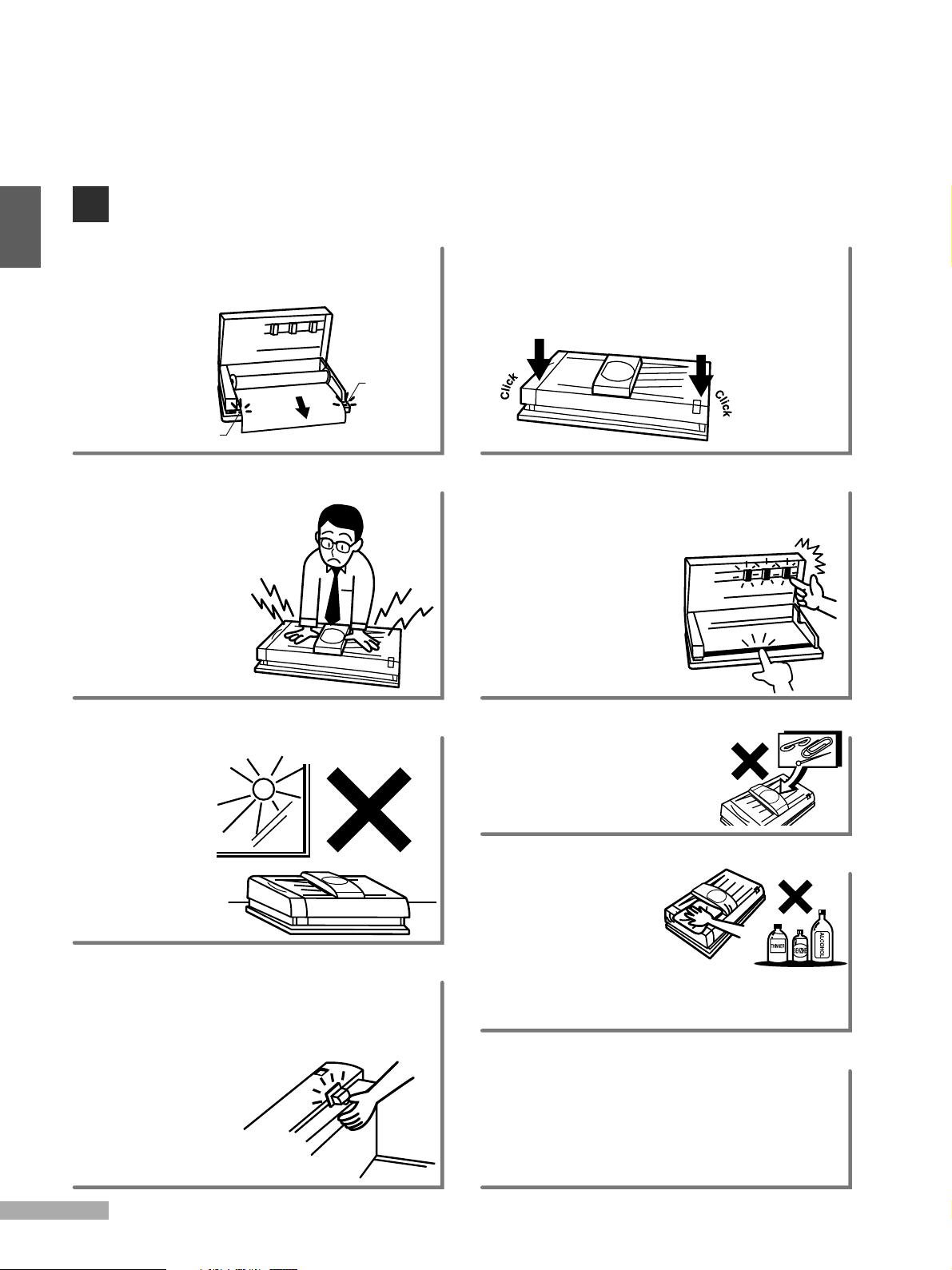
INSTRUCTIONS FOR PROPER USE OF THE PRINTER
1
• When installing paper, pull the end of the
roll out so that any slack is removed from
the paper. Align the paper with the guide
marks on either
side.
guide mark
guide mark
• Avoid pressing down on the
printer or scanner cover
while the printer is in
operation.
• Avoid pulling the
paper out of the
machine while
printing. Doing so
may affect the
quality of the poster.
• Hold the ends of the printer cover in both
hands and gently push the cover down
until locked in place.
• Be sure to switch the power off when
opening or closing the cover.
• Avoid contact with the thermal heads
(which retain heat) immediately after using
the printer.
• Be careful not to
damage the platen
rubber. Avoid wiping
the platen rubber
with alcohol or other
solvents.
• Avoid placing the printer in a location
where it is
subjected to
direct sunlight,
large amounts
of dust, or
near an air
conditioning or
heating unit.
When the printer is in use, the blade of the cutter is
•
designed so as not to protrude from the body of the
machine. However, when the printer cover is open,
pressing down on the cutter lever will cause the
blade to protrude. Exercise due
care to avoid cutting yourself.
• The cutter unit is made of
resin. Avoid pushing or
pulling on the cutter
with excessive force,
as doing so may damage it.
• Be careful to ensure that
pins, paper clips, and other
foreign objects are not
dropped inside the printer.
• Always use a soft, dry
cloth when cleaning
the printer.
• Avoid using
abrasive cleaners,
thinners, benzine, or alcohol in cleaning
the printer, as doing so may cause the
plastic to deteriorate or change color.
• Do not turn the power switch off during
the initializing or printing, as doing so may
affect output quality. Should the printer be
turned off at these times, turn the switch
on again, and wait until completion of the
initializing or printing.
6
Page 9

MAIN FEATURES OF THE POSTERPRINTER 3000
The PosterPrinter 3000 is designed to allow even first time users to quickly and easily
print high quality enlargements of letter sized documents.
normal mode
input
document
reverse mode
input
document
photo mode
Both horizontal and vertical signs and banners can be easily created from long input
documents.
1
Posters can be created in a variety of sizes.
Paper rolls are available in 23” and 17”
widths.
(33”x44” and 44”x58” size posters can
also be produced by attaching two print
outs together.)
17" 23"
A variety of paper types and colors are
available.
Direct Thermal Paper (DTP)
Cost effective and striking, direct thermal paper is availab le
in 6 colors, and is suitable for the creation of posters to be
displayed indoors.
Thermal Transfer Paper (TTP)
Similar to a regular type paper, thermal transfer paper
resists discoloration and is suitable for the creation of
posters which are to be displayed f or long periods of time.
Heavy Duty Poly Paper (HDP)
Made of plastic, HDP paper is waterproof, resists discoloration
and offers excellent durability which makes it suitable for the
creation of posters to be displayed outdoors.
Both printer and scanner are contained in
one compact and light unit, making
installation possible even in restricted
spaces.
scanner
printer
7
Page 10
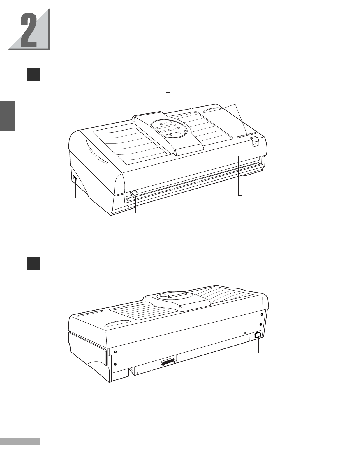
INDIVIDUAL PART NAMES
FRONT VIEW
2
power switch
document tray
control panel
scanner cover
cutter unit
document bay
cutter base
print outlet
paper guide
open/close knob
printer cover
REAR VIEW
AC inlet
power supply
interface board
(optional)
8
Page 11
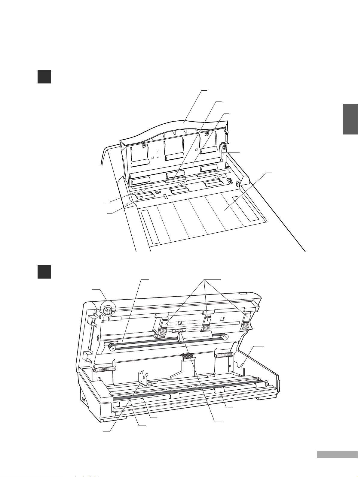
SCANNER
platen glass
document feed roller
scanner cover
document eject roller
platen roller
2
cogged belt
document bay
PRINTER
cutter unit
paper bracket (left)
(adjustable according to paper roll width)
cogged belt
platen rubber
cutter base
thermal heads
paper bracket (right)
paper feed roller
paper sensor
9
Page 12

CONTROL PANEL
10
9
8
2
2
3
7
No.
1
MESSAGE display
2
PAPER TYPE key
3
MODE key
4
OUTPUT SIZE key
5
CONTRAST key
6
START/STOP key
7
FEED key
8
CLEAR key
9
ONLINE lamp
10
READY lamp
6
Remove the protective covering
from the control panel before use.
Name Function
The message display indicates the paper type and output color, mode,
output size, contrast, and any operating/error messages.
Press the paper type key to set the type of paper installed in the
printer (DTP, TTP, HDP). If the paper type is set incorrectly,
contrast on the poster may be affected.
Press the mode key to set the desired mode
(normal, photo, reverse).
Press the output size key to set the desired output size.
Press the contrast key to lighten or darken contrast in accordance
with the input document.
Press the start/stop key to either start printing, or to stop
the printing process midway.
Press the feed key to feed the paper through the printer
(approximately 3"/77mm at a time).
The clear key is mainly used when printing in online mode.
(Refer to the Interface Kit User's Guide.)
The printer is in online mode with a computer when this lamp is lit.
The printer is ready to use when this lamp is lit.
1
4
5
Caution
10
Page 13

Message Display
Display Contrast
For posters of normal contrast
To slightly darken posters
To darken posters
To lighten posters
To slightly lighten posters
paper type output color
mode output size
Paper Types
Setting paper type and a description of each
There are three types of paper, direct
thermal paper (DTP), thermal transfer paper
(TTP) and heavy duty poly paper (HDP).
Choose the paper type according to usage.
Refer to ‘SUPPLIES’, p27.
Direct Thermal Paper (DTP)
Cost effective and striking, direct thermal paper is available in 6
colors, and is suitable for the creation of posters to be displayed
indoors.
Thermal Transfer Paper (TTP)
Similar to a regular type paper, thermal transfer paper resists
discoloration and is suitable for the creation of posters which are to
be displayed for long periods of time.
Heavy Duty Poly Paper (HDP)
Made of plastic, HDP paper is waterproof, resists discoloration and
offers excellent durability which makes it suitable for the creation of
posters to be displayed outdoors.
Output colors and the message display
Pressing the paper type key for at least one
second when the paper type is indicated on the
message display will change the direction of the
arrow (to the right) to display the sequence of
output colors. Each time the paper key is
pressed, the following color will be indicated.
Press the key again for at least one second. The
arrow will change back to the left. (Press the
start/stop key to hold the output color.)
Mode
contrast
Note that if a color is selected on the display
differing to the output color of the paper
installed in the printer, the output color will not
change to the specified color.
DTP
press for
at least 1second
BLACK
RED
BLUE
ORANGE
BK/Y
BK/LB
BK/P
OTHER
TTP
press for
at least 1second
BLACK
RED
BLUE
GREEN
OTHER
HDP
press for
at least 1second
BLACK
RED
OTHER
2
Mode
NORMAL
PHOTO
REVERSE
Display
NORMAL
PHOTO
REVERSE
Output Size
Output sizes are displayed in the following
order according to the width of paper installed in the printer.
Paper size Output size
A1 (23")
A2 (17")
17" 14" 12" 10" 8"
23" 20" 17" 33"( ) 33"( )
44"( ) 44"( )
Document Type
For all (non-photographic) input documents
For photographs
Black and white areas of the input document are reversed on the poster
Contrast
There are five levels of contrast, as indicated
by the * mark.
11
Page 14

BEFORE PRINTING
k
INSTALLING PAPER
3
After releasing the open/close knob,
lift the printer cover gently until it
comes to rest in the open position.
printer cover
open/close knob
Insert the end caps into both ends of
the paper roll.
Note that the triangular marks on the end caps are designed as
guides to show the amount of paper remaining on the roll.
printing side of paper (inside)
triangular mark
Set the left paper bracket into position
according to the width of the paper to
be used.
Refer to ‘Setting the left paper bracket’,p13.
paper bracket (left)
paper bracket (right)
Install the paper in the printer.
Install the paper roll so that the end of the paper runs out
from the bottom of the roll.
guide mar
end cap
The paper remaining from the tip of the mark:
direct thermal paper: approximately 19.7ft/6m.
thermal transfer paper and HDP paper: approximately 26.2ft/8 m.
Align the paper with the guide marks.
When installing paper, pull the end of the roll out
approximately 8”/200mm, so that any slack is removed from
the paper. Align the paper with the guide marks on either
side.
paper
about
8"/200mm
guide markguide mark
If the paper is installed incorrectly, the poster may be printed at
an angle, or wrinkles may occur.
paper
guide mark
Hold the ends of the printer cover with
both hands and gently push the cover
down until locked in place.
Check that both ends are closed properly.
click
click
If the printer is turned on, about 1.8”/45mm of paper will
automatically advance.
12
Page 15

Cut the paper.
Move the cutter in a downward horizontal sliding
motion while holding the paper out from the printer.
3
PROPER USE OF THE CUTTER
Lightly press down on the cutter lever
while holding the edge of the paper
underneath it.
Using force on the paper cutter has no advantageous effect.
Pressing down lightly is sufficient. The cutter may be used from
either direction.
When the printer cover is open, pressing
down on the paper cutter lever will cause the
blade to protrude.
Exercise due care to avoid cutting yourself.
Setting the left paper bracket
Setting the bracket in the printer
Install part A of the bracket according to
the paper size label marks, in order 1 2
left paper bracket
Adjusting the left paper bracket
If the paper (with end caps attached) does
not fit properly in the paper bracket, loosen
the adjustment knob and move the paper
bracket so that the paper can be installed
properly.
correct set position
Move the cutter unit
in a sliding motion
towards the right
to cut the paper.
Caution
end cap
left paper bracket
A
2
adjustment knob
paper size label
1
thermal paper
adjustment knob
13
Page 16

4
BASIC FUNCTIONS
PRINTING IN NORMAL MODE
input
document
Turn the power switch on. Press the paper type key to select the
type of paper being used.
Press the paper type key to match the paper indicated on the display
to the type of paper in use.
The paper type is shown here.
power switch
Caution
Do not turn the power switch off when the
printer is initializing or printing.
Press the mode key to set the printer
in normal mode.
'NORMAL' is shown here.
Caution
Note that it will be impossible to achieve
normal print contrast if the paper type
indicated on the message display is not the
same as the paper actually being used.
Press the output size key to select the
size of print desired.
The output size is shown here.
14
Page 17

Press the contrast key to select the
level of contrast desired.
Place the original into the document
bay face down.
Make sure the original is placed firmly along
the document guide closest to you, and into
the scanner until it stops.
4
Press the start/stop key to scan the
original. The printing process will
begin.
If you wish to stop printing mid-way press the start/stop key
again.
When the printing process is complete,
cut the print with the paper cutter.
Move the cutter in a downward horizontal sliding
motion while holding the paper out from the printer.
What to do when a ‘document jam’ error occurs
1. Open the scanner cover to remove the
original.
2. Reinsert the original until it stops, and
press the start/stop key.
If the original is not placed into the scanner until it stops, an error
may occur.
15
Page 18

PRINTING IN PHOTO MODE
photograph
4
Press the paper type key to select the
type of paper being used.
The paper type is shown here.
Place the original into the document
bay face down. Press the start/stop
key to begin printing.
photo mode
Press the mode key to set the printer
in photo mode. Select the desired
output size and level of contrast.
'PHOTO' is shown here.
Points to note when using photo mode
•Text portions are sometimes printed in slightly lighter colors.
If this happens, set the print contrast to a darker position.
•White areas on photographs may appear with dot-shaped
blotches in the print.
If this happens, set the print contrast to a lighter position.
•Horizontal and/or vertical lines may appear at regular intervals
on the print. This is normal and does not indicate an error in the
printing process.
•Yellow portions of photographs are sometimes poorly
reproduced.
• Printing speed in photo mode is slower than that of normal
mode.
16
Page 19

PRINTING IN REVERSE MODE
input
document
Press the paper type key to select the
type of paper being used.
The paper type is shown here.
Place the original into the document
bay face down. Press the start/stop
key to begin printing.
reverse mode
Press the mode key to set the printer
in reverse mode. Select the desired
output size and level of contrast.
'REVERSE' is shown here.
Points to note when using reverse mode
• The printer is designed to monitor the temperature of the
thermal heads and to control printing speed so as to prevent
them from overheating.
(If this happens, a ‘SLOW MODE’ message will appear on the
message display.)
4
17
Page 20

PRINTING DIFFERENT POSTER SIZES
DIVISION PRINTING
Printing two halves of a larger poster from one input document is called division printing.
Using A1(23”) paper to produce a 44”x58” size poster
Select the paper type, mode and
contrast. Set the output size so that
on the message
input
document
it appears as 44x58
display.
division print
5
Place the original into the document
bay face down. Press the start/stop
key to begin printing.
Make sure the original is placed firmly along
the document guide closest to you, and into
the scanner until it stops.
The left side of the original will be
printed first. When the printing
process is complete, cut the print with
the cutter.
When the left side is complete, the output size on the message
display will automatically change to 44x58
.
18
cutting mark
Page 21

;;
;;
Insert the original
once more into the
document bay, making
sure it faces the same
direction. Press the start/
stop key to begin printing
the right side of the
original.
Note that the two halves will
not be aligned properly if the
original is not placed correctly
into the document bay.
The right half of the
original will then be
printed. When the printing
process is complete, cut
the print with the cutter.
Paste the two sides of
the print together to
form a single poster.
When printing in divisions, cutting
marks are automatically printed on the
output.
Pasting two output sheets together
1. Cut away or fold back the excess margin
area of the first sheet, using the cutting
marks provided as a guide.
2. Align the first output sheet with the
second one so that the edge of the first is
against the cutting marks of the second,
and so the printed images of both halves
are properly lined up. Once one sheet has
been laid over the other, fix lightly into
place by applying tape to both ends of the
output sheets.
3. Apply a longer strip of tape over the tapes
first applied and cut away any excess
when both halves of the output have been
fixed together.
• Discoloration and fading may result depending on the type of
tape used.
• The cutting marks are to be used as guides when cutting.
• If the left and right sides do not align properly, adjust the image of
one side so that they do.
cutting mark
If you wish to print only the right side of
the original, press the output size key
until 44x58
display, and then press the start/stop key.
Cut or fold
appears on the message
Lightly apply tape
to hold in place
Apply tape to
fix into place
5
19
Page 22

5
PRINTING POSTERS SMALLER THAN THE PAPER SIZE
Procedure for printing posters smaller in width than the paper size
Using A1(23”) paper to produce a 20”x27” size poster
Select the paper type, mode and
contrast. Set the output size so that
it appears as 20x27 on the message
display.
Place the original into the document
bay face down. Press the start/stop
key to begin printing.
Make sure the original is placed firmly along
the document guide closest to you, and into
the scanner until it stops.
When the printing process is
complete, cut the print with the
cutter.
Move the cutter in a downward horizontal
sliding motion while holding the paper out
from the printer.
20
Cut away the excess margin area,
using the cutting marks provided as a
guide.
When printing posters of smaller width than the paper size,
cutting marks are automatically printed on the output.
cutting mark
excess
margin
cutting mark
Page 23

PRINTING BANNERS FROM LONG INPUT DOCUMENTS
Both horizontal and vertical signs and banners can be easily created from long input documents.
long input document
banner output
Press the paper type
key to select the type
of paper being used.
Points to note in printing banners
• Make sure the original is placed firmly along the document guide
closest to you, and into the scanner until it stops. Failing to do
so may result in an error.
• The banner will not be aligned properly if the original is not
placed correctly into the document bay.
• Always check the amount of remaining paper before printing
banners.
Refer to ‘CHECKING THE AMOUNT OF REMAINING PAPER’,
p25.
Select the desired
mode, level of
contrast and output
size.
Place the original into
the document bay
face down.
Press the start/stop key to
begin printing.
5
21
Page 24

ADDITIONAL FUNCTIONS
FUNCTION MODE
The following parameters can be input into the printer, to adjust printing functions and quality.
Function Description and Messages
Function / Description Message display
The direction of the image can be changed to create
a mirror image of the original.
MODE key CONTRAST key
0:
The poster is printed in its original direction
1:
Image direction
0:NORMAL 1:MIRROR
The poster is printed as a mirror image
of the original
Initially, the printer is set at0.
The white gaps between pages can be eliminated when printing
banners from a series of original sheets.
Caution
¥IfÔNoÕ is selected for page gap,
cutting marks will not be printed on
the poster.
Page gapVertical line adjustmentHorizontal line adjustmentPrinting power
¥IfÔNoÕ is selected for page gap, be
sure to press the paper feed key
before cutting the banner.
margins
0:
The poster is printed without gaps between
0:NO
the pages
1:
The poster is printed with gaps between
the pages
Initially, the printer is set at1.
1:YESinput documents
hold
6
Vertical lines which may show up on the printed
image can be adjusted to appear less conspicuous.
vertical
lines
For dark lines, press the mode key to reduce the
setting level. For white lines, press the contrast
key to increase the setting level.
Note that it is difficult to completely eliminate
lines that appear on the output document.
Horizontal lines which may show up on the printed
image can be adjusted to appear less conspicuous.
output direction
horizontal
lines
For dark lines, press the mode key to reduce the
setting level. For white lines, press the contrast
key to increase the setting level.
Note that it is difficult to completely eliminate lines
that appear on the output document.
output direction
Thermal head printing power can be adjusted to any of
19 levels. Press the mode key (-) and the contrast key
(+) to shift the setting one level in that direction.
-4 ¥ ¥ ¥ +0 ¥¥¥+4
minimum normal maximum
9 levels
Initially, the printer is set at+0.
-8 ¥ ¥ ¥ +0 ¥¥¥+8
minimum normal maximum
17 levels
Initially, the printer is set at+0.
-9 ¥ ¥ ¥ +0 ¥¥¥+9
minimum normal maximum
19 levels
22
Initially, the printer is set at+0.
Page 25

Setting Functions
Press the mode key
for at least 3 seconds
to set the printer in
function mode.
press for at least
3 seconds
Use the mode and
contrast keys to
select the parameters
as desired.
The ‘IMAGE DIRECTION’ screen will be
displayed.
Selecting different items in
function mode
Repeatedly pressing the paper type key
will display all of the functions in function
mode.
Press the start/stop
key to store the input
data.
'H' (hold) will be displayed.
Press the paper type
key to select the
desired function.
IMAGE DIRECTION
PAGE GAP
VERTICAL LINE
HORIZONTAL LINE
PRINTING POWER
Press the output size
key for at least 3
seconds to revert to the
original message display.
press for at least
3 seconds
6
Repeat steps 2 - 4 to set
additional parameters.
Checking Current Setting
Pressing the output size key for at least
3 seconds when the printer is in normal
mode displays the first setting screen.
Pressing the output size key for a further
3 seconds displays the second setting
screen. Pressing the output size key
again will revert the screen to
the original message display.
press for at least
3 seconds
original screen
press at least 3
setting screen 1
press at least 3
setting screen 2
seconds
seconds
PAGE GAP
VERTICAL LINE
IMAGE DIRECTION
PRINTING POWER
HORIZONTAL LINE
press at least 3 seconds
23
Page 26

REMAINING PAPER MODE
Use the remaining paper mode to check how much paper remains on the roll in use.
In addition, if the paper roll is changed midway, the amount of remaining paper can be
printed on the roll for future reference.
Setting the Amount of Remaining Paper
6
Press the clear key for at least 3
seconds.
press for at least
3 seconds
The ‘INPUT RESIDUAL’ screen will be
displayed. Input the amount of
remaining paper.
For new rolls of direct thermal paper:
Each time the paper type key is pressed, the display shows
‘85’ or ‘98’. Input 98 feet.
For new rolls of thermal transfer paper or HDP paper:
Each time the paper type key is pressed, the display shows
‘85’ or ‘98’. Input 85 feet.
For rolls of paper that are already used:
Input the amount using the mode key (-) and contrast key (+).
Each time either key is pressed, the number advances 1ft.
further in that direction.
The ‘RESIDUAL’ screen in remaining
paper mode will be displayed. Press
the start/stop key.
Press the start/stop key to store the
input data.
'H' (hold) will be displayed.
Press the start/stop key for at least 3
seconds to revert to the ‘RESIDUAL’
screen in remaining paper mode.
24
press for at least
3 seconds
Press the clear key for at least 3
seconds to revert to the original
message display.
press for at least
3 seconds
Page 27

Checking the Amount of Remaining Paper
press for at least
3 seconds
Press the clear key for
at least 3 seconds.
press for at least
3 seconds
The ‘RESIDUAL’
screen in remaining
paper mode will be
displayed. The amount of
remaining paper is
displayed in feet.
Printing the Amount of Remaining Paper
Press the clear key for at least 3
seconds.
Press the clear key
for at least 3 seconds
to revert to the
original message display.
The ‘RESIDUAL’ screen in remaining
paper mode will be displayed. Press
the clear key.
press for at least
3 seconds
The ‘PRINT RESIDUAL’ screen in
paper remaining mode will be
displayed. Press the start/stop key.
6
When the printing process is
complete, the message display will
revert to the original screen.
25
Page 28

SCANNING/PRINTING AREAS
SCANNING AREA
(for letter-sized originals)
(0.20/5) (0.20/5)
(0.20/5) (0.20/5)
8.50/216
8.11/206
scanning area
(0.12/3)
10.75/273
10.98/279
(0.12/3)
PRINTING AREA
If printing posters smaller than the paper
size, cutting marks are automatically
printed on the paper.
Note, however, that if “no page gap” is
selected, cutting marks will not be printed.
8.50/216
8.11/206
scanning area
(0.12/3)
original length
(0.12/3)
output direction
cutting mark
r
(2.17/55)
(0.20/5)(0.20/5)
7
q
wt
(1/25)
cutting mark
yleft margin u
1.18/ 30
0.87/ 22
0.87/ 22
0.87/ 22
6.61/168
0.87/ 22
0.91/ 23
0.87/ 22
0.87/ 22
0.87/ 22
0.87/ 22
1.18/ 30
cutting mark position
16.53/ 420
20.16/ 512
16.53/ 420
6.81/ 173
22.17/ 563
1.22/ 31
8.27/ 210
10.08/ 256
11.61/ 295
14.37/ 365
paper size output size q
A1(23") 17"x22"
A2(17")
20"x27"
23"x31"
33"x44" (L)
33"x44" (R)
44"x58" (L)
44"x58" (R)
8"x11"
10"x14"
12"x16"
14"x19"
17"x22"
ey
u
paper lengthwprinted lengtheprinted widthrupper margintlower margin
21.54/ 547
27.05/ 687
31.26/ 794
44.0/1117
44.0/1117
58.30/1481
58.30/1481
11.46/ 291
13.86/ 352
15.94/ 405
19.33/ 491
21.54/ 547
18.50/ 470
24.02/ 610
28.23/ 717
40.95/1040
40.95/1040
55.27/1404
55.27/1404
8.43/ 214
10.83/ 275
12.91/ 328
16.30/ 414
18.50/ 470
14.13/ 359
18.27/ 464
21.57/ 548
15.87/ 403
15.87/ 403
21.57/ 548
21.57/ 548
6.38/ 162
8.27/ 210
9.76/ 248
12.52/ 318
14.13/ 359
2.36/ 60
2.36/ 60
2.36/ 60
2.36/ 60
2.36/ 60
2.36/ 60
2.36/ 60
2.36/ 60
2.36/ 60
2.36/ 60
2.36/ 60
2.36/ 60
(0.67/ 17)
(0.67/ 17)
(0.67/ 17)
(0.67/ 17)
(0.67/ 17)
(0.67/ 17)
(0.67/ 17)
(0.67/ 17)
(0.67/ 17)
(0.67/ 17)
(0.67/ 17)
(0.67/ 17)
*Measurements in the table are nominal, and may change slightly depending on paper type, mode and environment. (unit: inch/mm)
26
-
-
Page 29

SUPPLIES
DESCRIPTION
There are 3 types of paper for use in printing with the PosterPrinter 3000.
Direct Thermal Paper (DTP), Thermal Transfer Paper (TTP) and Heavy Duty Poly Paper (HDP).
Direct Thermal Paper (DTP)
•Direct Thermal Paper is used to easily create posters, banners,
and materials to be displayed indoors.
• Inexpensive and striking, there are a total of 6 colors of Direct Thermal Paper.
Thermal Transfer Paper (TTP)
• Remove the ink film after printing to reveal a high quality printed image.
•Similar to plain paper which resists discoloration, Thermal Transfer Paper is suitable for
use in creating signs or posters to be displayed over long periods of time. Thermal Transfer
Paper may also be written on with waterproof markers, and laminated for further
protection.
Heavy Duty Poly Paper (HDP)
•Made of plastic, HDP Paper is waterproof and offers excellent durability which makes it
suitable for use in printing posters or banners which need no further lamination or protection for displaying outdoors.
•Similar to TTP, the ink film is removed after printing to reveal a high quality printed image.
• HDP Paper may also be written on with waterproof markers.
27
8
Page 30

POINTS TO NOTE WHEN USING POSTERPRINTER SUPPLIES
Points Common to All Types of PosterPrinter Supplies
• Never put paper in places subject to high temperatures, as doing so may result in
discoloration.
• Once a package of paper has been opened, keep it away from places subject to excessively
high or low levels of humidity. Failing to do so may cause the paper to expand or shrink,
which may make installation in the printer impossible.
•Never store paper in a place where it will be subjected to direct sunlight, as doing so may
result in discoloration.
Direct Thermal Paper (DTP)
•When displaying posters keep them away from direct sunlight. Failing to do so may result
in discoloration or fading.
•Always use water-based markers to write on posters.
•Never use plastic erasers, vinyl holders, and other writing and art equipment containing
solvents or fluorescents. They could cause the image to fade.
• Never rub the surface of posters strongly with a hard object, as doing so may cause
discoloration.
Thermal Transfer Paper (TTP) / Heavy Duty Poly Paper (HDP)
•Waterproof markers can be used to write on posters printed on thermal transfer paper.
Note, however, that the use of pens or markers with solvents may cause the ink on the
printed face of the poster to dissolve or smudge.
• Be careful when removing ink film from thermal transfer paper to do so in the proper
manner (see diagrams below).
8
REMOVING INK FILM FROM THERMAL TRANSFER AND HDP PAPER
Place the paper on the top of a desk or other level surface and hold it down with one hand.
Peel off the ink film slowly from left to right using a empty paper core or similar object.
28
Page 31

TROUBLESHOOTING
ERROR MESSAGES AND RESPONSES
If an error message appears on the display, follow the responses outlined below. If the printer
fails to function properly even after corrective action has been taken, contact the dealer from
whom you purchased your PosterPrinter 3000.
Error Message Description
The original has not been detected
by the scanner within the
programmed time period.
The original has jammed in the
scanning unit.
The scanner cover is open.
The printer cover is open.
The paper has not been installed.
The paper has not been loaded
correctly.
The thermal heads have
overheated.
When the power is turned on, or
after an error has occurred, the
shuttle unit has not moved back
into home position.
There is some sort of failure with
the printer.
Response
Press the start/stop key to revert
to the initial screen. Reset the
original and press the start/stop
key again.
Open the scanner cover and
remove the input document.
Firmly close the scanner cover.
Firmly close the printer cover.
Install a paper roll.
Reload the paper roll.
Turn the power off, wait for at
least three minutes, and then turn
the printer on again.
Turn the power off, clean the
shuttle shaft, and gently move the
shuttle unit into home position
(on the right of the printer) with
your hands. Turn the printer on
again.
Turn the power off and then on
again.
If the printer fails to function
properly even after corrective
action has been taken, contact
the dealer from whom you
purchased your PosterPrinter
3000. Be sure to tell your dealer
which of the error messages was
displayed.
9
29
Page 32

TROUBLESHOOTING
If a problem occurs during the printing process, follow the remedies outlined below. If the
printer fails to function properly even after corrective action has been taken, contact the
dealer from whom you purchased your PosterPrinter 3000.
Problem Description and Remedies
9
No.
The printer does not work even though
1
the power switch has been turned on.
2
Spots or lines appear on the printed poster.
1) If vertical lines appear
on the poster.
2) If horizontal lines appear
on the poster.
3) If spots appear periodically
on the poster.
4) If the left side of the
printed image does not
appear.
3
The printed image is not aligned
properly.
4
The printed image does not appear
(blank output).
Printed images or text are excessively
5
thin or light.
The paper roll loaded is too tight or too
6
loose in the brackets.
Description Remedy Ref.
Check that the power cord has been plugged in properly.
• Clean the platen glass in the scanner unit.
• If vertical lines appear on the poster at the thermal head
intervals, perform the 'Vertical line adjustment' in function
mode.
• Clean the thermal heads.
(It is recommended that you clean the thermal heads when
using Thermal Transfer Paper and HDP Paper after using
Direct Thermal Paper. )
• If horizontal lines appear on the poster at roughly
0.8inches/20mm intervals, perform the 'Horizontal line
adjustment' in function mode.
• Check to see if the surface of the platen rubber is clean.
• Clean the surface of the platen rubber if needed.
• The printer cover is not closed properly.
Open the cover and reclose it firmly holding both ends.
• Check to ensure that the scanner cover and printer cover
are closed properly.
•
Check to ensure that the paper roll has been installed properly.
• Clean the document feed rollers and/or paper feed rollers if
necessary.
• Check to ensure that the paper roll has been installed
properly.
• Check to ensure that the original has been placed face
down in the document bay.
• Set the contrast level to darker position.
• If the images or text on the original are too light, change to
a better copy of the original where possible.
• Check that the type of paper indicated on the message
display matches the type actually being used.
• Paper rolls may expand or shrink with changes in humidity
levels. Loosen the adjustment knob and move the left
paper bracket until the paper can be installed properly, or
install a new paper roll.
P3
P33
P22
P32
P22
P32
P12
P12
P15
P12
P32
P33
P12
P15
P11
P11
P13
30
Page 33

No.
Tone of the images can not be
7
reproduced in darker areas.
The printed poster does not appear.
8
The printer does not start to print even
9
after the start/stop key has been
pressed.
Spots or marks appear in the margin area.
10
A document jam occurs.
11
The printing process is unexpectedly
12
slow.
(An “SLOW MODE” message will appear
on the display.)
A black band appears on the back of the
13
print.
The printer makes a rattling or grating
14
noise, or the “SHUTTLE ERROR”
message appears on the display.
The ink sheet (thermal transfer paper,
15
HDP paper) has a lot of wrinkles in it.
White bubbles appear on the printed
16
surface (thermal transfer paper, HDP
paper).
The poster is printed as a mirror image
17
of the original.
Low contrast on the message display.
18
Description Remedy Ref.
• Set the contrast level to lighter position to reduce the
density.
• If the images on the original are too dark, change to a
better copy of the original where possible.
• Check that the type of paper indicated on the message
display matches the type actually being used.
• Open the cover of the printer and check to see if the paper
is caught in the paper feed rollers.
• Check that the printer cover is closed properly.
• Place the original into the document bay until it stops.
• The printer will not scan transparent documents. Make a
copy on plain paper and restart the process.
• Check to see if an error message appears on the message
display.
• Clean the thermal heads.
• Clean the platen glass in the scanner unit.
• Open the scanner cover and remove the original.
• Check that the scanner cover is closed properly.
• If a document jam occurs again, check that the original has
been set properly.
• The printer automatically switches to a lower speed when
the thermal heads overheat. This typically occurs when
printing posters with large black areas or when printing in
reverse mode. This is normal, and does not indicate an
error in the printing process.
• A black band is printed on the direct thermal paper, to
indicate that the paper roll is nearly finished. Change the
paper roll when the band appears.
• Clean the shuttle shaft.
• Remove the packaging material in the shuttle shaft unit.
• Check that the type of paper indicated on the message
display matches the type actually being used.
• Check that the type of paper indicated on the message
display matches the type actually being used.
• Change the setting in function mode ('IMAGE DIRECTION')
to 'NORMAL'.
• Remove the protective covering on the control panel.
P11
P11
P12
P15
P29
P32
P33
P15
P15
P17
P32
P2
P11
P11
9
P22
P10
31
Page 34

CLEANING THE PRINTER
If one of the following problems occurs, clean the printer parts outlined below.
Problem
1
The paper does not feed properly
2
The printer makes a rattling or grating noise during printing
3
Horizontal lines appear periodically on the printed image
4
Vertical lines appear on the printed image
5
The original is not scanned properly
PRINTER
shuttle shaft
thermal heads
Part to Clean
Paper feed roller
Shuttle shaft
Thermal heads
Platen glass
Document feed rollers, platen roller,
document eject rollers
heater element
10
platen rubber
cutter base
Paper feed rollers
Wipe with a soft cloth moistened with water.
Wipe again with a soft, dry cloth.
Platen rubber/cutter base
Wipe with a soft, dry cloth.
Caution
Be careful not to damage the platen rubber.
Avoid wiping the platen rubber with alcohol or
other solvents.
32
paper feed roller
Shuttle shaft
If the shaft becomes dirty, the printer will
not function properly. Wipe the shaft
carefully with a soft cloth.
Thermal heads
When the thermal heads have cooled (at
least 2 minutes after the printer has been
switched off) wipe the heater element
vertically with a soft, dry cloth.
If the thermal heads are particularly dirty, apply
a small amount of isopropyl alcohol to the
cloth. (Never touch the print heads directly
with your hands.)
Page 35

SCANNER
Platen glass
Wipe with a soft, dry cloth. If particularly dirty, use a soft cloth
moistened with water. Wipe again with a soft, dry cloth.
Document feed rollers/platen roller/document eject rollers
Wipe with a soft cloth moistened with water.
Wipe again with a soft, dry cloth.
platen glass
document feed roller
scanner cover
document eject roller
platen roller
Caution
Always remove the printer power plug from the wall socket before
cleaning the printer.
•Do not use organic solvents such as benzine, alcohol, thinners or
cleaners in cleaning the printer.
• Do not use detergent in cleaning the thermal heads.
• Be careful not to scratch the platen rubber as the quality of the print may
be affected.
• The scanner cover opens to an angle of approximately 70 degrees.
Do not attempt to open the cover any further.
10
33
Page 36

SPECIFICATIONS
Type
Scanning system
Scanning resolution
Input size
Input format
Printing system
Printing modes
Printing resolution
Paper size
Paper types
Output sizes
Paper supply
Paper cutting
Print size and
printing speed
desktop type printer
fixed contact image sensor
400 dpi
letter size, banner (8 1/2” wide)
sheet paper, thickness 50 - 350 microns
thermal printing
normal, photo, reverse, online (optional)
300 dpi
A1(23”), A2(17”) wide paper rolls
FUJI FILM Poster Printer paper
Direct Thermal Paper (DTP), Thermal Transfer Paper (TTP), Heavy Duty Poly Paper (HDP)
8"x11", 10"x14", 12"x16", 14"x19", 17"x22", 20"x27", 23"x31"
(33"x44" and 44"x58" are printed in two pieces)
banner
continuous feed roll paper
bidirectional manual cutter
(calculated as being roughly equivalent to length of document times specified enlargement)
Output size
17"x22"
23"x31"
Enlargement
(line magnification)
approx.1.7
approx.2.6
Normal • Reverse modes Photo modes
DTP
1min 00sec
1min 20sec
TTP • HDP DTP TTP • HDP
1min 10sec
1min 35sec
1min 50sec
2min 35sec
1min 58sec
2min 48sec
Warm-up time
Noise level
Dimensions/weight
Power supply
Power consumption
Operating environment
Items included in package
Optional accessory
Supplies
approx. 8 seconds
approx. 53 dB (A)
approx. 28.1 (W) x 12.4(D) x 8.5 (H) inches; approx. 31 lb.
approx. 715 (W) x 315 (D) x 215 (H) mm; approx. 14 kg
AC120V ±10% ; 50/60 Hz
at standby: approx. 15W; printing: approx. 210W
temperature: 50° - 86 °F; relative humidity: 20 - 80% RH
paper bracket unit (1), end caps (2), power cord, User's Guide
interface kit
platen rubber, thermal heads, cutter unit, cutter base
34
Page 37

INDEX
A
AC inlet 8
B
banner 7,21
C
cleaning printer 32
clear key 10
cogged belt 8,9
contrast key 10
control panel 8,10
cutter 13
cutter base 8,9,32
cutter unit 8,9
cutter, using the 13
cutting marks 18,19,20,26
D
direct thermal paper (DTP) 7,11,27,28
division printing 18
document bay 8,9
document eject roller 9,33
document feed roller 9,33
document jam 15
document tray 8
E
end cap 2,13
error messages 29
F
feed key 10
function mode 22
G
guide marks 12
H
heavy duty poly paper (HDP) 7,11,27,28
horizontal line adjustment 22
I
image direction, setting 22
ink film 28
input document, long 7,21
interface board 8
M
making 20" x 27" posters 20
making 44" x 58" posters 18
message display 10,11
mode key 10
N
normal mode 7,14
O
online lamp 10
open/close knob 8,12
output colors on message display 11
output size key 10
P
page gap, setting 22
paper 11,27,28
paper bracket (right) 9,12
paper bracket (left) 2,9,12
paper feed roller 9,32
paper guide 8
paper type key 10
paper sensor 9
paper, installing 12
pasting two output sheets together 19
photo mode 7,16
platen glass 9,33
platen roller 9,33
platen rubber 9,32
plug 3
power cord 2,3
power supply 8
power switch 3,8,14
print outlet 8
printer cover 8
printing area 26
printing on A1(23”) paper 18,20
printing power, setting 22
R
ready lamp 10
remaining paper mode 24
remaining paper, setting 24
reverse mode 7,17
S
scanner cover 8,9,33
scanning area 26
shuttle shaft 32
socket, three prong 3
start/stop key 10,15
T
thermal head 9,32
thermal transfer paper (TTP) 7,11,27,28
triangular mark 12
V
vertical line adjustment 22
35
Page 38

FUJI PHOTO FILM CO., LTD.
26-30, Nishiazabu 2-chome, Minato-ku, Tokyo 106-8620, Japan.
053DC514C-305106-AA•0001-7q Printed in Japan
 Loading...